EP2738325A1 - Anti-panic cylinder - Google Patents
Anti-panic cylinder Download PDFInfo
- Publication number
- EP2738325A1 EP2738325A1 EP12195035.6A EP12195035A EP2738325A1 EP 2738325 A1 EP2738325 A1 EP 2738325A1 EP 12195035 A EP12195035 A EP 12195035A EP 2738325 A1 EP2738325 A1 EP 2738325A1
- Authority
- EP
- European Patent Office
- Prior art keywords
- gear
- cylinder
- lock
- lock cylinder
- larger gear
- Prior art date
- Legal status (The legal status is an assumption and is not a legal conclusion. Google has not performed a legal analysis and makes no representation as to the accuracy of the status listed.)
- Granted
Links
- 230000002426 anti-panic effect Effects 0.000 title claims description 15
- 230000006835 compression Effects 0.000 description 5
- 238000007906 compression Methods 0.000 description 5
- 230000008878 coupling Effects 0.000 description 5
- 238000010168 coupling process Methods 0.000 description 5
- 238000005859 coupling reaction Methods 0.000 description 5
- 238000013475 authorization Methods 0.000 description 3
- 230000005540 biological transmission Effects 0.000 description 3
- 230000000903 blocking effect Effects 0.000 description 2
- 229910000952 Be alloy Inorganic materials 0.000 description 1
- 229910000639 Spring steel Inorganic materials 0.000 description 1
- 208000012886 Vertigo Diseases 0.000 description 1
- 229920001971 elastomer Polymers 0.000 description 1
- 239000000806 elastomer Substances 0.000 description 1
- 238000003780 insertion Methods 0.000 description 1
- 230000037431 insertion Effects 0.000 description 1
- 239000000463 material Substances 0.000 description 1
- 230000007935 neutral effect Effects 0.000 description 1
- 238000009420 retrofitting Methods 0.000 description 1
Images


Classifications
-
- E—FIXED CONSTRUCTIONS
- E05—LOCKS; KEYS; WINDOW OR DOOR FITTINGS; SAFES
- E05B—LOCKS; ACCESSORIES THEREFOR; HANDCUFFS
- E05B17/00—Accessories in connection with locks
- E05B17/04—Devices for coupling the turning cylinder of a single or a double cylinder lock with the bolt operating member
- E05B17/047—Devices for coupling the turning cylinder of a single or a double cylinder lock with the bolt operating member with rotating output elements forming part of cylinder locks, e.g. locking cams of double cylinder locks
-
- E—FIXED CONSTRUCTIONS
- E05—LOCKS; KEYS; WINDOW OR DOOR FITTINGS; SAFES
- E05B—LOCKS; ACCESSORIES THEREFOR; HANDCUFFS
- E05B15/00—Other details of locks; Parts for engagement by bolts of fastening devices
- E05B15/04—Spring arrangements in locks
-
- E—FIXED CONSTRUCTIONS
- E05—LOCKS; KEYS; WINDOW OR DOOR FITTINGS; SAFES
- E05B—LOCKS; ACCESSORIES THEREFOR; HANDCUFFS
- E05B9/00—Lock casings or latch-mechanism casings ; Fastening locks or fasteners or parts thereof to the wing
- E05B9/04—Casings of cylinder locks
- E05B2009/046—Cylinder locks operated by knobs or handles
-
- E—FIXED CONSTRUCTIONS
- E05—LOCKS; KEYS; WINDOW OR DOOR FITTINGS; SAFES
- E05B—LOCKS; ACCESSORIES THEREFOR; HANDCUFFS
- E05B9/00—Lock casings or latch-mechanism casings ; Fastening locks or fasteners or parts thereof to the wing
- E05B9/04—Casings of cylinder locks
- E05B2009/047—Means for returning cylinder locks to their neutral position
Definitions
- the invention relates to an automatic return device for a cam of a lock cylinder, and a lock cylinder equipped therewith, preferably for use in anti-panic locks.
- An anti-panic lock sometimes called a panic lock, is a lock that can be opened at any time, whether it is locked or not, from the inside by pressing the lever handle or a special crossbar.
- This antipanic function e.g. in case of fire the possibility of escape through the emergency exit doors guaranteed.
- the cam of the lock cylinder inserted in the lock is in a neutral position or rest position, otherwise he can block the pusher, so that the Lock does not open.
- the cam of the lock cylinder must be in a lower position, as it could otherwise hinder the (anti) panic function of the lock.
- only very specific positions or special angle ranges are permitted as rest position to ensure anti-panic function.
- a lock cylinder which has a cam.
- a core is offset from the axis.
- a ball bearing is provided on the eccentric core.
- a spring is further arranged radially to the ball bearing, which exerts a corresponding radial compressive force on the ball bearing. This causes the shaft and the associated locking bit to be automatically returned to a rest position after each turning operation in which it locks no blocking of a handle operation and thus the Anitpanikfunktion comes.
- this reset system has the disadvantage that it requires a relatively large amount of space to dispose the eccentric core, the ball bearing and the spring. For this reason, it is also not suitable for every type of lock cylinder, since it can not be integrated without additional significant structural measures in such a rule.
- the object of the invention is therefore to provide an automatic return device, which reliably moves the cam of a lock cylinder in a predetermined range and which can be easily integrated into a lock cylinder, in particular in a lock cylinder, which is suitable to be used in an anti-panic lock.
- the invention relates to an automatic return device, preferably for a lock cylinder in a special lock / mortise lock or a special lock case with a Antipaukfunktion (antipanic lock) can be used.
- the invention relates to an anti-panic cylinder or an anti-panic lock cylinder.
- a mortise lock is a locking device in which a lock cylinder is used as a drive for the actual lock device.
- a mechanical lock cylinder is the part of the lock which can be actuated by means of a mechanical key, and essentially consists essentially of a housing and a rotatable cylinder core.
- locking cylinders such as profile cylinders (eg standard Euro profile cylinder according to DIN 18252 / EN1303), round cylinders (eg Swiss Round, Scandinavian Round), oval cylinders (eg Scandinavian Oval, British Oval) and many more.
- profile cylinders eg standard Euro profile cylinder according to DIN 18252 / EN1303
- round cylinders eg Swiss Round, Scandinavian Round
- oval cylinders eg Scandinavian Oval, British Oval
- semi-cylinders if they only be closed and / or actuated from one side and of double cylinders, if they are closable and / or operable from both sides.
- mechanical knob cylinders are known to be operated on one side with a key and on the other side with a fixed mounted rotary knob.
- a profile cylinder is the most common form of security door locks used today in Germany or Austria. Consequently, the invention will be described preferably with reference to a profile cylinder. However, the present invention is applicable to any type of lock
- the lock cylinder according to the invention has a locking bar rotatable with respect to its longitudinal axis, with which the bolt of the lock can be actuated.
- the lock cylinder according to the invention has a return mechanism that biases the cam to preclude a predetermined angular range for the rest position of the Sch Camillbarts or to allow a certain angular range for the rest position.
- the reset mechanism according to the invention has the advantage that a return member, which provides the required force for the return mechanism, can be accommodated outside the core region of the lock cylinder without significantly cutting the diameter of the core.
- a large return member for example a large spring element, and thus a high degree of effectiveness is made possible without impairing the basic functionality determined by the core.
- the return mechanism according to the invention has the advantage that the return mechanism exclusively uses the space of the lock cylinder itself, whereby compatibility with conventional, preferably standardized, locks can be ensured.
- the return mechanism includes at least one return member that provides the required force for the return mechanism.
- the return mechanism comprises at least a first larger gear which is connected to the cam, preferably non-rotatably, and a second smaller gear which is engageable with the first larger gear or come, so that a on the second smaller gear by the return member engaging force can be transmitted from the smaller gear to the first larger gear.
- the relative terms “smaller” and “larger” gear refer to each other, making it clear that the larger gear is larger than the smaller gear.
- size should refer to the diameter or radius of the gears, preferably the corresponding Wälznikischen dur. Although the two gears are different in size, the two gears should preferably have the same number of teeth.
- the smaller gear is a wheel that has evenly distributed over the entire circumference of the wheel teeth, whereas the larger gear over an angular range of less than 360 ° (dentate angle range) , preferably less than 300 ° evenly distributed the same number of teeth.
- the larger gear wheel has no teeth over an angular range of> 30 °, but preferably less than 180 °, which will be referred to below as "tooth-free region.”
- the larger gear has at least one "toothed angular region” and at least one "tooth-free area”. More preferably, the larger gear has exactly one "toothed angle range” and exactly one "tooth-free area", wherein the sum of these two angular ranges gives 360 °.
- engagement of the two gears means transmission between two rotations of the two gears, i. when the teeth are engaged, they engage positively, and thus slip-free into each other.
- a condition may occur in which the two gears are not engaged, i. There is a slip over the tooth-free area.
- the first larger gear has no teeth over an angular range of 30-90 °.
- the first and second gears are arranged to one another such that a 360 ° rotation of the first larger gear from the rest position preferably also causes a 360 ° rotation of the second smaller gear.
- the smaller gear and / or the larger gear is formed as a spur gear.
- the larger and / or the smaller gear than External gear or internal gear are formed.
- the toothing can also be straight (paraxial), oblique (helical toothing) or beveled (arrow toothing).
- the invention is not limited to this type of gears and configurations in the form of bevel gear, Kegelplanrad, crown wheel and spindle wheel, etc. are also conceivable.
- the lock cylinder according to the invention is designed as a profile cylinder (PZ cylinder).
- the cylinder core of the profile cylinder is preferably rotatably mounted and preferably at least a portion of the cylinder core via a clutch with the lock bit rotatably coupled.
- the lock cylinder is an electronic knob cylinder having one or two knobs.
- a coupling mechanism between the knob and the lock bit is preferably provided which, depending on an authentication, couples the knob to the lock bit or decouples it or leaves it in the decoupled state.
- both knobs can be coupled to the lock bit temporarily, for unlocking or closing, or only one of the two knobs, wherein the other knob is then preferably non-rotatably or permanently fixedly coupled to the lock bit.
- the first larger gear is arranged in the lock cylinder, that it is rotatable about the longitudinal axis of the lock cylinder.
- the axis of rotation of the first larger gear is preferably parallel to the longitudinal axis of the lock cylinder, preferably through the center axis of the cylinder core.
- the lock cylinder according to the invention in particular in the form of a profile cylinder, has a cylindrical portion (cylinder core) and a radially projecting, preferably U-shaped, section thereof. These two sections are often referred to as cylindrical bearing section and flange section.
- the first larger gear is preferably arranged in the cylindrical portion of the profile cylinder and the second smaller gear is arranged in the protruding portion of the profile cylinder.
- the ratio of the diameter of the first larger gear to the diameter of the second smaller gear is in the range from 17/8 - 15/10, preferably at about 17/10.
- the ratio of the "pitch circle diameter" of the two gears is in the range of 17/8 - 15/10.
- the distance along the pitch circle diameter at the larger gear in the toothed area is equal to or substantially equal to the circumference of the smaller gear along the pitch circle diameter.
- a profile cylinder according to DIN 18252 has a Wegendurclunesser of 17mm in the cylindrical section and the width of the radially projecting portion is 10mm.
- the return mechanism according to the invention has at least one return member, which has at least one spring element, which is preferably arranged in a profile cylinder in the protruding portion.
- the spring element is not limited to a specific type and can be configured in principle as a torsion spring, spring or tension spring.
- Non-limiting examples of possible spring elements are compression spring, tension spring, leaf spring, helical compression spring, helical tension spring, tortuous torsion spring, torsion spring, straight torsion spring, spiral spring, diaphragm spring, leaf spring, disc spring, elastomer spring, Evolutfeder, ring spring and coil spring.
- the spring element is not limited to a particular material, but preferably made of spring steel or a copper-beryllium alloy.
- the return member or the spring element engages at an eccentric position on the smaller gear, whereby the return member biases the smaller gear in a predefined position.
- the restoring member should act on this eccentric position.
- a person skilled in the art could be present on the smaller gear a projecting eccentric pin on which a train or compression spring attacks.
- a recess for example, an eccentric bore to be formed in the smaller gear, in which a rod is used on the then the spring element transmits the restoring force.
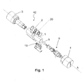
- FIG. 1 shows a first embodiment of the invention.
- a double-clutch electronic cylinder with the two knobs 3 and 4, which are attached to the two ends of the longitudinal axis A of the lock cylinder.
- the lock cylinder is a profile cylinder with a round cylindrical core portion 1 and a radially projecting U-shaped portion 5.
- the knob 3 should be an inner knob, which is preferably permanently rotatably coupled to the cam 2 , so that when the lock cylinder inserted in a lock the cam 2 can always be rotated via the knob 3.
- the inner knob 3 contains important electronic Parts used to authenticate a user.
- the knob 4 is used as an outer knob and is detachably mounted in this illustrated embodiment on the cylinder core 6, wherein the cylinder core is preferably rotatably mounted in the cylindrical portion 1 of the lock cylinder.
- the removable outer knob 4 allows easy insertion of the lock cylinder in a lock case.
- a coupling or a coupling mechanism between the outer knob 4 and the cam 2 preferably provided in the rotatable cylinder core portion 6 between the cam 2 and outer knob 4, so that rotation of the outer knob 4 in a rotation of the Schschschbarts 2 takes place only in the coupled state, the again depends on a successful authentication.
- a signal is preferably transmitted through the cylinder core, preferably through the partially cylindrical or ring-shaped cam 2 as an electronic signal to an actuator in the coupling element, so that a coupling of the outer knob. 4 can be done with the cam 2.
- the reset mechanism In order to bias the lock bit 2 into a rest position or a rest area, the reset mechanism according to the invention is provided which has a (first) larger gearwheel 20 and a (second) smaller gearwheel 10 as essential components.
- the larger gear 20 is arranged concentrically with the cam or the annular part of the lock bar 2, so that the larger gear and the cam lock about a common axis (A; Fig. 3a ).
- the larger gear 20 is preferably accommodated as large as possible within the cylindrical portion 1 of the lock cylinder.
- the smaller gear 10 is housed in the illustrated embodiment in the radially projecting, U-shaped portion (here downwards) of the profile cylinder and also designed as large as possible within the available external dimensions.
- the return mechanism according to the invention comprises a return element, preferably in the form of at least one spring.
- this return element may also have a plurality of springs and additional lever elements, which according to the invention preferably in the radially projecting, downwardly directed, U-shaped section are housed.
- This has the decisive advantage that the mechanism of the return element can be accommodated away from the rotatably mounted cylinder core 6, so that the already proven design of a double-knob cylinder, which should allow a rotational movement of the cylinder core 6 or data transmission within the cylinder core 6, is not hindered.
- Fig. 1 In addition, some design features are shown, which are not described in more detail, since they are not relevant to the understanding of the return mechanism according to the invention.
- FIGS. 2a and 2b show essential parts of the return mechanism according to the invention in two different positions, wherein the representation of FIGS. 2a and 2b essentially represents a cross section of the lock cylinder according to the invention perpendicular to the longitudinal axis A of the cylinder.
- the FIGS. 2a and 2b show the area in which the cam 2 can be in the rest area.
- the show FIGS. 2a and 2b the extreme positions of the rest area, that is, the cam 2 can move in the lower area without force and remain in each of these positions without the return mechanism moves the cam 2.
- FIG. 2a shows the maximum deflection to the right over the angle ⁇ / 2, that is, a position in which the uppermost of the gears 13 of the small gear 10 is still within the tooth-free portion 22, but abuts the first tooth of the tooth portion 21 of the large gear 20 left
- the maximum force-free deflection of the lock bar 2 to the left is shown in which the uppermost tooth of the gears 13 of the small gear 10 is also still in tooth-free area 22 of the large gear, but to the first tooth of the tooth portion 21 on the other side of the teeth-free area 22nd of the larger gear 20 abuts.
- the uppermost tooth is meant with respect to the rest position of the small gear, that is, the tooth which is closest to the eccentric point 11 discussed below.
- the deflection corresponds to ⁇ / 2 to the left of the maximum deflection by ⁇ / 2 to the right, in which case the rest region can be described as ⁇ .
- This angle 80 ° corresponds essentially to the As soon as the gears 21 of the larger gear engage with the gears 13 of the smaller gear, the smaller gear 10 rotates and thus the eccentric point 11 of the small gear shifts from the in FIGS. 2a and 2b position shown; that is, the eccentric point 11 is turned down.
- the spring element 30, which in Fig. 4 is shown trying to counteract such a rotation of the eccentric point of attack 11, thus causing a bias of the eccentric point 11 upwards, causing the larger gear is turned back to the "rest position".
- FIGS. 2a and 2b shows a partial view of the return mechanism according to the invention.
- the combination of the smaller gear 10 with the larger gear 20 may be described as a gear unit with a drive element and an output member which are relatively movable to each other, wherein in an engaged state, the two gears 10 and 20 are positively in operative connection, so that a power transmission between the gears is achievable.
- the driven by the spring element gear can be referred to as a driving gear or pinion, the driven larger wheel as the output.
- the tooth shape of the two wheels is preferably an involute toothing. Since the two gears can move freely in the "tooth gap area" of the output, you could call the larger gear as "output with freewheel".
- Both gears 10, 20 are rotatably arranged and have the same number of teeth; eleven in the embodiment shown here.
- an operative connection exists when the teeth of the smaller gear 10 with the gears of the toothed (angle) area 21 of the larger gear 20 engage with each other.
- the larger gear Due to the "tooth space area” 22 (hereinafter also referred to as “tooth-free area”) in the larger gear 20, the larger gear can be moved via this tooth-free area 22 in a freewheeling state without a force from the smaller gear 10 transmitted to the larger gear 20 becomes. That is, when the larger gear 20 is in a position in which there is no operative connection to the small gear 10, then the return mechanism, the larger gear 22 can not rotate.
- the tooth-free Area 22 defines the "rest position” or the “rest area” in which the larger gear 20 can remain force-free and thus defines the area in which the cam 2 - which is preferably rotatably connected to the larger gear 20 - may remain to still the To ensure anti-panic function of the anti-panic lock.
- Fig. 4 shows similar to the FIGS. 2a and 2b a rest position within the rest area (freewheeling area), but with the additionally shown spring element 30 in the form of a compression spring.
- the compression spring 30 tries to push the eccentric attached to the small gear 10 pin 11 still up; is reached this upper position is the smaller gear 10 in the rest position.
- all the tooth elements of the smaller gear 10 and the larger gear 20 are made similar in geometry or identical to allow a safer intervention.
- the invention is not limited to this type of gears.
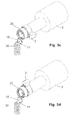
- the show FIGS. 3a to 3c and 5a to 5d an embodiment with the smaller gear 10 as a spur gear and the larger gear as a cylindrical sleeve with toothed elements 25 which extend in the axial direction of the sleeve.
- the larger gear thus resembles a Kegelplanrad.
- the gears may also be designed as bevel gears.
- FIGS. 3b and 3c schematically a lock cylinder according to the invention in positions in which the return mechanism would like to push the cam back into the rest position.
- Fig. 3a is essentially the same as in Fig. 4 position shown, but from the side.
- the cam 2 is directed vertically downwards, the eccentric pin 11 is in its rest position above, which is achieved by the pressure spring shown here purely by way of example, which exerts a force upward.
- the larger gear 20 is in the "free-running position" with respect to the smaller gear 10, that is, the cam 2 can by this vertically downward position by ⁇ / 2 to the right and left (in the side view to the rear or forward) force-free are moved without the return mechanism exerts a restoring force on the larger gear 20 and thus the cam.
- Fig. 3b the cam 2 is not visible because it extends perpendicular to the rear with respect to the plane of the paper.
- the positions of the locker of the FIGS. 3a and 3b are twisted by 90 °.
- a rotation of the smaller gear 10 from its rest position is achieved by turning a knob causes a rotation of the larger gear 20, whereby the teeth 25 of the larger gear 20 with the gears of the smaller gear 10 are engaged, so that the smaller gear 10th is rotated from the rest position. Therefore, the eccentrically mounted pin 11 is rotated from the uppermost position to a changed position.
- the spring 30 now tries to push the pin 11 upwards and thus generates a restoring force, i. a torque on the smaller gear 10, which in turn generates a torque on the larger gear 20.
- Fig. 3c shows a further extreme position in which the return spring 30 is maximally compressed, that is, the eccentric pin 11 is in the maximum downward position.
- the restoring mechanism according to the invention with the smaller and the larger gear 10, 20 is designed such that a complete 360 ° rotation of the pegs - and thus a corresponding 360 ° rotation of the larger gear - also causes a 360 ° rotation of the smaller gear 10, follows from the in Fig. 3c shown 180 ° rotation with respect to Fig. 3a Again, the smaller gear 10 and the larger gear 20 are engaged, so that a force exerted by the spring 30 force the eccentric pin 11 tries to push upward, creating a torque in the smaller gear 10th is generated, which in turn is transmitted to the larger gear 20.
- FIGS. 5a to 5d in which the inner knob 3 with the cam 2, which is rotatably coupled to the larger gear 20 is shown in perspective.
- the return mechanism only essential parts are shown, namely the smaller gear 10 and the return element 30 in the form of a spring, which acts on the eccentric pin 10 of the smaller gear 10.
- the position of the return mechanism of Fig. 5a corresponds essentially to the position Fig. 3a respectively.
- Fig. 4 The position of Fig. 5c corresponds essentially to the position of Fig. 3b that is, a 90 ° rotation of the SchOUGbarts 2 from the vertically downward position, which is centered within the rest position according to the invention.
- the invention also includes the exact or exact terms, features, numerical values, or ranges, etc., as above or below, of such terms, features, numerical values, or ranges in the context of terms such as "about, about, substantially,” Generally, at least, at least “etc.” (ie, “about 3” should also include “3” or “substantially radial” should also include “radial.")
- the term “or” also means “and / or”.
Abstract
Description
Die Erfindung betrifft eine automatische Rückstellvorrichtung für einen Schließbart eines Schließzylinders, sowie einen damit ausgestatteten Schließzylinder, vorzugsweise zum Einsatz in Antipanikschlössern.The invention relates to an automatic return device for a cam of a lock cylinder, and a lock cylinder equipped therewith, preferably for use in anti-panic locks.
Ein Antipanikschloss, manchmal auch als Panikschloss bezeichnet, ist ein Schloss das sich jederzeit, unabhängig davon, ob es abgeschlossen ist, oder nicht, von innen durch das Betätigen des Türdrückers oder eine spezielle Querstange öffnen lässt. Durch diese Antipanikfunktion wird z.B. im Brandfall die Fluchtmöglichkeit durch die Notausgangstüren gewährleistet. Durch die Betätigung des Türdrückers werden Riegel und Falle ins Schloss eingezogen. Hierzu ist es jedoch meist erforderlich, dass der Schließbart (oft auch als Nase, Mitnehmer, Schließglied oder Schließnocke bezeichnet) des im Schloss eingesetzten Schließzylinders sich in einer neutralen Position bzw. Ruheposition befindet, da er sonst den Drücker blockieren kann, so dass sich das Schloss nicht öffnen lässt. Häufig muss sich der Schließbart des Schließzylinders in einer unteren Position befinden, da er ansonsten die (Anti-)panikfunktion des Schlosses behindern könnte. Abhängig von dem Antipanikschloss sind nur ganz spezielle Positionen bzw. spezielle Winkelbereiche als Ruheposition zugelassen, um die Antipanikfunktion zu gewährleisten.An anti-panic lock, sometimes called a panic lock, is a lock that can be opened at any time, whether it is locked or not, from the inside by pressing the lever handle or a special crossbar. By this antipanic function, e.g. in case of fire the possibility of escape through the emergency exit doors guaranteed. By pressing the lever handle latch and latch are pulled into the lock. For this purpose, however, it is usually necessary that the cam (often referred to as nose, driver, closing member or closing cam) of the lock cylinder inserted in the lock is in a neutral position or rest position, otherwise he can block the pusher, so that the Lock does not open. Often, the cam of the lock cylinder must be in a lower position, as it could otherwise hinder the (anti) panic function of the lock. Depending on the anti-panic lock, only very specific positions or special angle ranges are permitted as rest position to ensure anti-panic function.
Aus der
Aufgabe der Erfindung ist es daher eine automatische Rückstellvorrichtung bereitzustellen, welche zuverlässig den Schließbart eines Schließzylinders in einen vorbestimmten Bereich bewegt und die leicht in einen Schließzylinder integriert werden kann, insbesondere in einen Schließzylinder, der geeignet ist in ein Antipanikschloss eingesetzt zu werden.The object of the invention is therefore to provide an automatic return device, which reliably moves the cam of a lock cylinder in a predetermined range and which can be easily integrated into a lock cylinder, in particular in a lock cylinder, which is suitable to be used in an anti-panic lock.
Diese Aufgabe wird mit einem automatischen Rückstellmechanismus gemäß Anspruch 1 bzw. einen Schließzylinder nach Anspruch 5 gelöst. Weitere bevorzugte Ausführungsformen sind in den weiteren Ansprüchen bzw. in den unten diskutierten Ausführungsformen beschrieben.This object is achieved with an automatic reset mechanism according to
Die Erfindung betrifft eine automatische Rückstellvorrichtung, vorzugsweise für einen Schließzylinder der in ein spezielles Schloss/Einsteckschloss bzw. einen speziellen Schlosskasten mit einer Antipaukfunktion (Antipanikschloss) eingesetzt werden kann. Insbesondere betrifft die Erfindung einen Antipanikzylinder bzw. einen Antipanikschließzylinder.The invention relates to an automatic return device, preferably for a lock cylinder in a special lock / mortise lock or a special lock case with a Antipaukfunktion (antipanic lock) can be used. In particular, the invention relates to an anti-panic cylinder or an anti-panic lock cylinder.
Ein Einsteckschloss ist eine Verriegelungsvorrichtung, bei der ein Schließzylinder als Antrieb für die eigentliche Schlossvorrichtung eingesetzt wird. Ein mechanischer Schließzylinder ist der mittels eines mechanischen Schlüssels zu betätigende Teil des Schlosses, und besteht im Wesentlichen meist aus einem Gehäuse und einem drehbaren Zylinderkern.A mortise lock is a locking device in which a lock cylinder is used as a drive for the actual lock device. A mechanical lock cylinder is the part of the lock which can be actuated by means of a mechanical key, and essentially consists essentially of a housing and a rotatable cylinder core.
Es gibt verschiedene Bauformen für Schließzylinder wie beispielsweise Profilzylinder (z.B. Standard-Europrofilzylinder gemäß DIN 18252/EN1303), Rundzylinder (z.B. Swiss Round, Scandinavian Round), Ovalzylinder (z.B. Scandinavian Oval, British Oval) u.v.m. Zudem spricht man von Halbzylindern, wenn sie nur von einer Seite schließbar und/oder betätigbar sind und von Doppelzylindern, wenn sie von beiden Seiten schließbar und/oder betätigbar sind. Auch sind mechanische Knaufzylinder bekannt, die auf einer Seite mit einem Schlüssel und auf der anderen Seite mit einem fest montierten drehbaren Knauf zu betätigen sind. Ein Profilzylinder ist die gebräuchlichste Form der heute in Deutschland bzw. Österreich verwendeten Sicherheits-Türschlösser. Nachfolgen wird die Erfindung deshalb vorzugsweise in Bezug auf einen Profilzylinder beschrieben. Die vorliegende Erfindung ist jedoch auf jegliche Art von Schließzylindern anwendbar, insbesondere auf die oben beispielhaft genannten Varianten, ohne darauf beschränkt zu sein.There are different types of locking cylinders such as profile cylinders (eg standard Euro profile cylinder according to DIN 18252 / EN1303), round cylinders (eg Swiss Round, Scandinavian Round), oval cylinders (eg Scandinavian Oval, British Oval) and many more. We also speak of semi-cylinders if they only be closed and / or actuated from one side and of double cylinders, if they are closable and / or operable from both sides. Also are mechanical knob cylinders are known to be operated on one side with a key and on the other side with a fixed mounted rotary knob. A profile cylinder is the most common form of security door locks used today in Germany or Austria. Consequently, the invention will be described preferably with reference to a profile cylinder. However, the present invention is applicable to any type of lock cylinders, particularly but not limited to the variants exemplified above.
Vorzugsweise ist der erfindungsgemäße Schließzylinder ein elektronischer Schließzylinder, der häufig auch als digitaler Schließzylinder bezeichnet wird oder in einer Ausführung mit einem Knauf bzw. zwei Knäufen als elektronischer Knaufzylinder bezeichnet wird. Insbesondere hat ein digitaler Schließzylinder die Form eines normalen Schließzylinders, wird vorzugsweise jedoch nicht mit einem mechanischen Schlüssel, sondern mit einem elektronischen Schlüssel betätigt. Gespeist wird der elektronische Schließzylinder vorzugsweise mittels Batterien. Diese batteriebetriebenen elektronischen Schließzylinder haben den Vorteil, dass eine komplizierte Verkabelung einzelnen Komponenten entfällt, sodass diese Art von Zylinder sich daher für eine unkomplizierte Nachrüstung von bestehenden mechanischen Anlagen eignet. Elektronische batteriebetriebene Schließzylinder gibt es prinzipiell in drei verschiedenen Ausführungen.
- i) Als mechanisch kodierten Zylinder mit einer zusätzlichen elektronischen Verriegelung z. B. über einen Sperrmagneten. Der Schlüssel enthält die nötige Elektronik vorzugsweise in der Schlüsselreide und wird über Kontakte oder auch kontaktlos auf Schließberechtigung überprüft.
- ii) Als ausschließlich elektronisch kodierten Zylinder. Der Schlüssel als solches wird vorzugsweise nur zum Drehen des Zylinders und als Identmittelträger benötigt. Diese Schlüssel können auch ein spezifisches mechanisches Profil enthalten, um auch die in einer Schließanlage enthaltenen rein mechanischen Zylinder zu schließen.
- iii) Als Einfach- bzw. Doppelknaufzylinder weist der Zylinder auf einer bzw. beiden Seiten der Türe einen Drehknauf auf, welcher eine rein elektronische Verriegelung ermöglicht (elektronischer Knaufzylinder). Erst nach rein elektronischer Überprüfung der Schließberechtigung erfolgt die Freigabe und der Drehknauf kann zum Öffnen bzw. Schließen bedient werden, wodurch der Schließbart gedreht wird. Ohne Berechtigung dreht zumindest einer der genannten Knäufe leer durch, oder blockiert. Als Identmittel wird beispielsweise ein Keyfob, ein Armband, eine Chipkarte (z.B. Mifare Chipkarte), eine Funkkarte (beispielsweise RFID Karte) oder ein passiver bzw. aktiver Transponder verwendet, ohne darauf beschränkt zu sein. Die vorliegende Erfindung ist auf jegliche Art von elektronischen Schließzylindern anwendbar, insbesondere auf die oben beispielhaft genannten Varianten, ohne darauf beschränkt zu sein. Im Folgenden wird die Erfindung beispielhaft anhand eines elektronischen Doppelknaufzylinders beschrieben.
- i) As a mechanically coded cylinder with an additional electronic lock z. B. via a blocking magnet. The key contains the necessary electronics, preferably in the key crayon and is checked via contacts or contactless for locking authorization.
- ii) As exclusively electronically coded cylinders. The key as such is preferably needed only for rotating the cylinder and as Identmittelträger. These keys may also contain a specific mechanical profile to close also the purely mechanical cylinders contained in a locking system.
- iii) As a single or double knob cylinder, the cylinder on one or both sides of the door on a knob, which allows a purely electronic locking (electronic knob cylinder). Only after a purely electronic check of the locking authorization is the release and the knob can for Opening and closing are operated, whereby the cam is rotated. Without authorization, at least one of the mentioned knobs turns off, or blocks. For example, a keyfob, a wristband, a chip card (eg Mifare chip card), a radio card (for example RFID card) or a passive or active transponder are used as identification means, without being limited thereto. The present invention is applicable to any type of electronic lock cylinders, in particular, but not limited to, the variants exemplified above. The invention will be described below by way of example with reference to an electronic double-knob cylinder.
Der erfindungsgemäße Schließzylinder weist einen bezüglich seiner Längsachse drehbaren Schließbart auf, mit dem der Riegel des Schlosses betätigt werden kann. Der erfindungsgemäße Schließzylinder verfügt über einen Rückstellmechanismus, der den Schließbart vorbelastet, um einen vorbestimmten Winkelbereich für die Ruheposition des Schließbarts auszuschließen bzw. einen bestimmten Winkelbereich für die Ruheposition zuzulassen.The lock cylinder according to the invention has a locking bar rotatable with respect to its longitudinal axis, with which the bolt of the lock can be actuated. The lock cylinder according to the invention has a return mechanism that biases the cam to preclude a predetermined angular range for the rest position of the Schließbarts or to allow a certain angular range for the rest position.
Der erfindungsgemäße Rückstellmechanismus hat den Vorteil, dass ein Rückstellglied, das die erforderliche Kraft für den Rückstellmechanismus liefert, außerhalb des Kernbereichs des Schließzylinders untergebracht werden kann ohne den Durchmesser des Kerns wesentlich zu beschneiden. Dadurch wird im Hinblick auf hohe Rückstellkräfte ein großes Rückstellglied, beispielsweise ein großes Federelement, und somit eine hohe Effektivität ermöglicht, ohne die durch den Kern bestimmte Grundfunctionalität zu beeinträchtigen.The reset mechanism according to the invention has the advantage that a return member, which provides the required force for the return mechanism, can be accommodated outside the core region of the lock cylinder without significantly cutting the diameter of the core. As a result, in view of high restoring forces, a large return member, for example a large spring element, and thus a high degree of effectiveness is made possible without impairing the basic functionality determined by the core.
Zudem hat der erfindungsgemäße Rückstellmechanismus den Vorteil, dass der Rückstellmechanismus ausschließlich den Bauraum des Schließzylinders selbst nutzt, wodurch Kompatibilität mit üblichen, vorzugsweise genormten, Schlössern gewährleistet werden kann.In addition, the return mechanism according to the invention has the advantage that the return mechanism exclusively uses the space of the lock cylinder itself, whereby compatibility with conventional, preferably standardized, locks can be ensured.
Der Rückstellmechanismus umfasst mindestens ein Rückstellglied, das die erforderliche Kraft für den Rückstellmechanismus liefert. Zudem umfasst der Rückstellmechanismus mindestens ein erstes größeres Zahnrad das mit dem Schließbart, vorzugsweise drehfest, verbunden ist und ein zweites kleineres Zahnrad das mit dem ersten größeren Zahnrad in Eingriff kommt bzw. kommen kann, sodass eine am zweiten kleineren Zahnrad durch das Rückstellglied angreifende Kraft vom kleineren Zahnrad auf das erste größere Zahnrad übertragen werden kann. Hierbei ist zu beachten, dass sich die relativen Begriffe "kleineres" und "größeres" Zahnrad aufeinander beziehen, wodurch klar wird, dass das größere Zahnrad größer ist als das kleinere Zahnrad. Zudem soll sich der Begriff der Größe auf den Durchmesser bzw. Radius der Zahnräder beziehen, vorzugsweise die entsprechenden Wälzkreisdurchmesser. Obwohl die beiden Zahnräder unterschiedlich groß sind, sollten die beiden Zahnräder vorzugsweise die gleiche Anzahl von Zähnen haben.The return mechanism includes at least one return member that provides the required force for the return mechanism. In addition, the return mechanism comprises at least a first larger gear which is connected to the cam, preferably non-rotatably, and a second smaller gear which is engageable with the first larger gear or come, so that a on the second smaller gear by the return member engaging force can be transmitted from the smaller gear to the first larger gear. It should be noted that the relative terms "smaller" and "larger" gear refer to each other, making it clear that the larger gear is larger than the smaller gear. In addition, the term size should refer to the diameter or radius of the gears, preferably the corresponding Wälzkreisdurchmesser. Although the two gears are different in size, the two gears should preferably have the same number of teeth.
Um dennoch einen Eingriff zwischen den beiden Zahnrädern zu ermöglichen ist es bevorzugt, dass das kleinere Zahnrad ein Rad ist, das über den gesamten Umfang des Rads gleichmäßig verteilt Zähne aufweist, wohingegen das größere Zahnrad über einen Winkelbereich von weniger als 360° (bezahnter Winkelbereich), vorzugsweise weniger als 300° die gleiche Anzahl von Zähnen gleichmäßig verteilt. Mit anderen Worten, das größere Zahnrad hat über einen Winkelbereich von >30°, aber vorzugsweise weniger als 180° keine Zähne, der im Folgenden "zahnfreier Bereich" genannt wird.. Vorzugsweise hat das größere Zahnrad mindestens einen "bezahnten Winkelbereich" und mindestens einen "zahnfreien Bereich". Weiter bevorzugt hat das größere Zahnrad genau einen "bezahnten Winkelbereich" und genau einen "zahnfreien Bereich", wobei die Summe dieser beiden Winkelbereiche 360° ergibt.In order to still allow engagement between the two gears, it is preferred that the smaller gear is a wheel that has evenly distributed over the entire circumference of the wheel teeth, whereas the larger gear over an angular range of less than 360 ° (dentate angle range) , preferably less than 300 ° evenly distributed the same number of teeth. In other words, the larger gear wheel has no teeth over an angular range of> 30 °, but preferably less than 180 °, which will be referred to below as "tooth-free region." Preferably, the larger gear has at least one "toothed angular region" and at least one "tooth-free area". More preferably, the larger gear has exactly one "toothed angle range" and exactly one "tooth-free area", wherein the sum of these two angular ranges gives 360 °.
Vorzugsweise ist mit Eingriff der beiden Zahnrädern eine Übertragung zwischen zwei Drehungen der beiden Zahnräder gemeint, d.h. wenn die Zähne in Eingriff sind, dann greifen sie formschlüssig, und somit schlupffrei ineinander. Aufgrund des zahnfreien Bereichs kann es aber zu einem Zustand kommen, bei dem die beiden Zahnräder nicht in Eingriff sind, d.h. es entsteht ein Schlupf über den zahnfreien Bereich. Vorzugsweise weist das erste größere Zahnrad über einen Winkelbereich von 30-90° keine Zähne auf.Preferably, engagement of the two gears means transmission between two rotations of the two gears, i. when the teeth are engaged, they engage positively, and thus slip-free into each other. However, due to the tooth-free region, a condition may occur in which the two gears are not engaged, i. There is a slip over the tooth-free area. Preferably, the first larger gear has no teeth over an angular range of 30-90 °.
Vorzugsweise sind das erste und zweite Zahnrad so zueinander angeordnet, dass eine 360° Drehung des ersten größeren Zahnrads aus der Ruheposition heraus vorzugsweise ebenfalls eine 360° Drehung des zweiten kleineren Zahnrads bewirkt.Preferably, the first and second gears are arranged to one another such that a 360 ° rotation of the first larger gear from the rest position preferably also causes a 360 ° rotation of the second smaller gear.
Vorzugsweise ist das kleinere Zahnrad und/oder das größere Zahnrad als Stirnrad ausgebildet. Zudem ist es denkbar, dass das größere und/oder das kleinere Zahnrad als Außenzahnrad bzw. Innenzahnrad ausgebildet sind. Die Verzahnung kann zudem gerade (achsparallel), schräg (Schrägverzahnung) oder gegenschräg (Pfeilverzahnung) ausgeführt sein. Die Erfindung ist jedoch nicht auf diese Art Zahnräder beschränkt und Ausgestaltungen in Form von Kegelrad, Kegelplanrad, Kronrad und Spindelrad usw. sind ebenso denkbar.Preferably, the smaller gear and / or the larger gear is formed as a spur gear. In addition, it is conceivable that the larger and / or the smaller gear than External gear or internal gear are formed. The toothing can also be straight (paraxial), oblique (helical toothing) or beveled (arrow toothing). However, the invention is not limited to this type of gears and configurations in the form of bevel gear, Kegelplanrad, crown wheel and spindle wheel, etc. are also conceivable.
Vorzugsweise ist der erfindungsgemäße Schließzylinder als Profilzylinder (PZ-Zylinder) ausgebildet. Der Zylinderkern des Profilzylinders ist vorzugsweise drehbar gelagert und vorzugsweise zumindest ein Teil des Zylinderkerns über eine Kupplung mit dem Schließbart drehfest koppelbar. Gemäß einer weiter bevorzugten Ausführungsform handelt es sich beim dem Schließzylinder um einen elektronischer Knaufzylinder, der einen oder zwei Knäufe aufweist. Bei einem Einzelknaufzylinder bzw. einem Halbzylinder mit nur einem Knauf ist vorzugsweise ein Kopplungsmechanismus zwischen Knauf und Schließbart vorgesehen, der in Abhängigkeit einer Authentifizierung den Knauf mit dem Schließbart koppelt bzw. entkoppelt bzw. im entkoppelten Zustand belässt. Bei einem Doppelknaufzylinder können beide Knäufe mit dem Schließbart temporär, für das Aufschließen bzw. Abschließen, gekoppelt werden oder nur einer der beiden Knäufe, wobei der andere Knauf dann vorzugsweise drehfest bzw. dauerhaft fest mit dem Schließbart gekoppelt ist.Preferably, the lock cylinder according to the invention is designed as a profile cylinder (PZ cylinder). The cylinder core of the profile cylinder is preferably rotatably mounted and preferably at least a portion of the cylinder core via a clutch with the lock bit rotatably coupled. According to a further preferred embodiment, the lock cylinder is an electronic knob cylinder having one or two knobs. In a single-knob cylinder or a half-cylinder with only one knob, a coupling mechanism between the knob and the lock bit is preferably provided which, depending on an authentication, couples the knob to the lock bit or decouples it or leaves it in the decoupled state. In a double-knob cylinder, both knobs can be coupled to the lock bit temporarily, for unlocking or closing, or only one of the two knobs, wherein the other knob is then preferably non-rotatably or permanently fixedly coupled to the lock bit.
Vorzugsweise ist das erste größere Zahnrad so im Schließzylinder angeordnet, dass es um die Längsachse des Schließzylinders drehbar ist. Mit anderen Worten, die Drehachse des erste größere Zahnrad verläuft vorzugsweise parallel zur Längsachse des Schließzylinders, vorzugsweise durch die Mittelachse des Zylinderkerns.Preferably, the first larger gear is arranged in the lock cylinder, that it is rotatable about the longitudinal axis of the lock cylinder. In other words, the axis of rotation of the first larger gear is preferably parallel to the longitudinal axis of the lock cylinder, preferably through the center axis of the cylinder core.
Der erfindungsgemäße Schließzylinder, insbesondere in Form eines Profilzylinders, weist einen zylindrischen Abschnitt (Zylinderkern) und einen davon radial abstehenden, vorzugsweise U-förmigen, Abschnitt auf. Diese beiden Abschnitte werden oft auch als zylindrischer Lagerabschnitt und Flanschabschnitt bezeichnet. Das erste größere Zahnrad ist vorzugsweise im zylindrischen Abschnitt des Profilzylinders angeordnet und das zweites kleineres Zahnrad im abstehenden Abschnitt des Profilzylinders angeordnet ist. Vorzugsweise liegt das Verhältnis der Durchmesser des ersten größeren Zahnrads zum Durchmesser des zweiten kleineren Zahnrads im Bereich von 17/8 - 15/10, vorzugsweise bei ca. 17/10. Vorzugsweise liegt das Verhältnis der "Wälzkreisdurchmesser" der beiden Zahnräder im Bereich von 17/8 - 15/10. Anders ausgedrückt ist die Strecke entlang des Wälzkreisdurchmessers am größeren Zahnrad im bezahnten Bereich gleich oder im Wesentlichen gleich zum Umfang des kleineren Zahnrads entlang des Wälzkreisdurchmessers.The lock cylinder according to the invention, in particular in the form of a profile cylinder, has a cylindrical portion (cylinder core) and a radially projecting, preferably U-shaped, section thereof. These two sections are often referred to as cylindrical bearing section and flange section. The first larger gear is preferably arranged in the cylindrical portion of the profile cylinder and the second smaller gear is arranged in the protruding portion of the profile cylinder. Preferably, the ratio of the diameter of the first larger gear to the diameter of the second smaller gear is in the range from 17/8 - 15/10, preferably at about 17/10. Preferably, the ratio of the "pitch circle diameter" of the two gears is in the range of 17/8 - 15/10. In other words, the distance along the pitch circle diameter at the larger gear in the toothed area is equal to or substantially equal to the circumference of the smaller gear along the pitch circle diameter.
Ein Profilzylinder nach DIN 18252 hat im zylindrischen Abschnitt einen Außendurclunesser von 17mm und die Breite des davon radial abstehenden Abschnitts beträgt 10mm. Um diese äußeren Gegebenheiten besonders effektiv auszunutzen wird man vorzugsweise im zylindrischen als auch im radial abstehenden Abschnitt ein möglichst großes Zahnrad einbauen. Wenn man beispielsweise ein Zahnrad einbaut, das stets 1 mm Abstand von den Außenmaßen hat, erhält man zwei Zahnräder mit 17mm-2mm= 15mm bzw. 10mm-2mm = 8 mm Außendurchmesser.A profile cylinder according to DIN 18252 has a Außenendurclunesser of 17mm in the cylindrical section and the width of the radially projecting portion is 10mm. In order to utilize this external conditions particularly effectively, it is preferable to install as large a gearwheel as possible in the cylindrical as well as in the radially projecting section. For example, if you install a gear that is always 1 mm away from the outer dimensions, you get two gears with 17mm-2mm = 15mm or 10mm-2mm = 8mm outer diameter.
Der erfindungsgemäße Rückstellmechanismus hat mindestens ein Rückstellglied, das mindestens ein Federelement aufweist, das in einem Profilzylinder vorzugsweise im abstehenden Abschnitt angeordnet ist. Das Federelement ist nicht auf eine bestimmte Art begrenzt und kann prinzipiell als Torsionsfeder, Biegefeder oder Zugfeder ausgestaltet sein. Als nicht einschränkende Beispiele für mögliche Federelemente sind Druckfeder, Zugfeder, Blattfeder, Schraubendruckfeder, Schraubenzugfeder, gewundene Torsionsfeder, Schenkelfeder, gerade Torsionsfeder, Biegefeder, Membranfeder, Blattfeder, Tellerfeder, Elastomerfeder, Evolutfeder, Ringfeder und Schraubenfeder zu nennen. Auch ist das Federelement nicht auf ein bestimmtes Material beschränkt, vorzugsweise jedoch aus Federstahl oder einer Kupfer-Beryllium-Legierung hergestellt.The return mechanism according to the invention has at least one return member, which has at least one spring element, which is preferably arranged in a profile cylinder in the protruding portion. The spring element is not limited to a specific type and can be configured in principle as a torsion spring, spring or tension spring. Non-limiting examples of possible spring elements are compression spring, tension spring, leaf spring, helical compression spring, helical tension spring, tortuous torsion spring, torsion spring, straight torsion spring, spiral spring, diaphragm spring, leaf spring, disc spring, elastomer spring, Evolutfeder, ring spring and coil spring. Also, the spring element is not limited to a particular material, but preferably made of spring steel or a copper-beryllium alloy.
Vorzugsweise greift das Rückstellglied bzw. das Federelement an einer exzentrischen Stelle am kleineren Zahnrad an, wodurch das Rückstellglied das kleinere Zahnrad in eine vordefinierte Lage vorspannt. Es bieten sich für einen Fachmann wiederum mehrerer Möglichkeiten, wie das Rückstellglied an diese exzentrische Stelle angreifen soll. Beispielsweise könnte am kleineren Zahnrad ein abstehender Exzenterzapfen vorhanden sein, an dem eine Zug oder Druckfeder angreift. Gemäß einer weiteren Ausführungsform könnte anstelle eines Exzenterzapfens eine Vertiefung, beispielsweise eine Exzenterbohrung, im kleineren Zahnrad ausgebildet sein, in die ein Stab eingesetzt wird auf den dann das Federelement die Rückstellkraft überträgt.Preferably, the return member or the spring element engages at an eccentric position on the smaller gear, whereby the return member biases the smaller gear in a predefined position. Again, there are several possibilities for a person skilled in the art how the restoring member should act on this eccentric position. For example, could be present on the smaller gear a projecting eccentric pin on which a train or compression spring attacks. According to a further embodiment, instead of an eccentric pin, a recess, For example, an eccentric bore to be formed in the smaller gear, in which a rod is used on the then the spring element transmits the restoring force.
Im Folgenden werden bevorzugte Ausführungsformen der vorliegenden Erfindung unter Bezugnahme auf die Figuren ausführlich beschrieben. Es zeigen:
- Fig. 1
- eine Explosionszeichnung eines elektronischen Doppelknaufzylinders in der Ausgestaltung eines Profilzylinders;
- Fig. 2a - 2b
- eine Teilansicht des erfindungsgemäßen Rückstellmechanismus;
- Fig. 3a-3c
- Seitenansichten des erfindungsgemäßen Rückstellmechanismus in drei verschiedenen Zuständen;
- Fig. 4
- eine den
Figuren 2a und 2b ähnliche Teilansicht des erfindungsgemäßen Rückstellmechanismus mit einem dargestellten Rückstellglied; und - Fig. 5a -5d
- perspektivische Teilansichten des erfindungsgemäßen Rückstellmechanismus in vier verschiedenen Zuständen.
- Fig. 1
- an exploded view of an electronic double knob cylinder in the configuration of a profile cylinder;
- Fig. 2a - 2b
- a partial view of the return mechanism according to the invention;
- Fig. 3a-3c
- Side views of the return mechanism according to the invention in three different states;
- Fig. 4
- a the
FIGS. 2a and 2b similar partial view of the return mechanism according to the invention with a return member shown; and - Fig. 5a -5d
- partial perspective views of the return mechanism according to the invention in four different states.
Um den Schließbart 2 in eine Ruheposition bzw. einen Ruhebereich vorzuspannen wird der erfindungsgemäße Rückstellmechanismus bereitgestellt, der als wesentliche Bauteile ein (erstes) größeres Zahnrad 20 und ein (zweites) kleineres Zahnrad 10 aufweist. Vorzugsweise ist das größere Zahnrad 20 konzentrisch mit Schließbart bzw. dem ringförmigen Teil des Schließbarts 2 angeordnet, so dass sich das größere Zahnrad und der Schließbart um eine gemeinsame Achse (A; siehe
Aufgrund der symmetrisch ausgestalteten Ausführungsform entspricht die Auslenkung um β/2 nach links der maximalen Auslenkung um β/2 nach rechts, wobei in diesem Fall der Ruhebereich als β beschrieben werden kann. In der dargestellten Ausführungsform beträgt der Wert von β/2 = 40°, so dass der Winkelbereich des Ruhebereichs 2 x β/2 = 80° beträgt. Dieser Winkel 80° entspricht im Wesentlichen dem Winkelbereich des zahnfreien Bereichs 22 auf dem großen Zahnrad 20. Sobald die Zahnräder 21 des größeren Zahnrads mit den Zahnrädern 13 des kleineren Zahnrads in Eingriff kommen, verdreht sich das kleinere Zahnrad 10 und somit verschiebt sich der exzentrische Angriffspunkt 11 des kleinen Zahnrads aus der in
Mit anderen Worten, eine Wirkverbindung besteht wenn die Zähne des kleineren Zahnrads 10 mit den Zahnrädern des bezahnten (Winkel)bereichs 21 des größeren Zahnrads 20 ineinander greifen. Aufgrund des "Zahnlückenbereich" 22 (im Folgenden auch als "zahnfreier Bereichs" bezeichnet) im größeren Zahnrad 20 kann das größere Zahnrad über diesen zahnfreien Bereich 22 in einem Freilaufzustand bewegt werden, ohne dass eine Kraft vom kleineren Zahnrad 10 auf das größere Zahnrad 20 übertragen wird. D.h. wenn das größere Zahnrad 20 sich in einer Lage befindet, in dem keine Wirkverbindung zum kleinen Zahnrad 10 besteht, dann kann der Rückstellmechanismus das größere Zahnrad 22 nicht verdrehen. Nochmals in anderen Worten, der zahnfreie Bereich 22 definiert die "Ruheposition" bzw. den "Ruhebereich" in dem das größer Zahnrad 20 kraftfrei verbleiben kann und definiert somit den Bereich in dem der Schließbart 2 - der mit dem größeren Zahnrad 20 vorzugsweise drehfest verbunden ist - verbleiben darf, um dennoch die Antipanikfunktion des Antipanikschlosses zu gewährleisten.In other words, an operative connection exists when the teeth of the
Sollte der Schließbart sich in dem oberen Bereich befinden (siehe beispielsweise
Vorzugsweise sind alle Zahnelemente des kleineren Zahnrads 10 und des größeren Zahnrads 20 in ihrer Geometrie ähnlich bzw. identisch ausgeführt, um ein sichereres Eingreifen zu ermöglichen. Die Erfindung ist jedoch nicht auf diese Art von Zahnrädern beschränkt. Beispielsweise zeigen die
Im Gegensatz zu den
In
Ein Verdrehen des kleineren Zahnrads 10 aus seiner Ruheposition wird dadurch erreicht, dass ein Drehen eines Knaufs ein Drehen des größeren Zahnrads 20 bewirkt, wodurch die Zähne 25 des größeren Zahnrads 20 mit den Zahnrädern des kleineren Zahnrads 10 in Eingriff kommen, sodass das kleinere Zahnrad 10 aus der Ruheposition verdreht wird. Daher wird der exzentrisch angebrachte Zapfen 11 aus der obersten Position in eine veränderte Position gedreht. Die Feder 30 versucht nun den Zapfen 11 nach oben zu drücken und erzeugt somit eine Rückstellkraft, d.h. ein Drehmoment am kleineren Zahnrad 10, das wiederum ein Drehmoment am größeren Zahnrad 20 erzeugt.A rotation of the
Schließlich wird noch auf die
Die Erfindung umfasst ebenfalls die genauen oder exakten Ausdrücke, Merkmale, numerischen Werte oder Bereiche usw., wenn vorstehend oder nachfolgend diese Ausdrücke, Merkmale, numerischen Werte oder Bereiche im Zusammenhang mit Ausdrücken wie z.B. "etwa, ca., um, im Wesentlichen, im Allgemeinen, zumindest, mindestens" usw. genannt wurden (also "etwa 3" soll ebenfalls "3" oder "im Wesentlichen radial" soll auch "radial" umfassen). Der Ausdruck "bzw." bedeutet überdies "und/oder".The invention also includes the exact or exact terms, features, numerical values, or ranges, etc., as above or below, of such terms, features, numerical values, or ranges in the context of terms such as "about, about, substantially," Generally, at least, at least "etc." (ie, "about 3" should also include "3" or "substantially radial" should also include "radial.") The term "or" also means "and / or".
Claims (13)
wobei das erste größere Zahnrad (11) im zylindrischen Abschnitt (1) des Profilzylinders angeordnet ist und das zweites kleineres Zahnrad (10) im abstehenden Abschnitt (5) des Profilzylinders angeordnet ist, und wobei das Verhältnis des Teilkreisdurchmessers des ersten größeren Zahnrads (20) zum Teilkreisdurchmesser des zweiten kleineren Zahnrads (20) im Bereich von 17/8 - 15/10 liegt, vorzugsweise bei ca. 17/10.Locking cylinder according to claim 1 or 2, wherein the lock cylinder (42) has a cylindrical portion (1) and a radially projecting portion (5),
wherein the first larger gear (11) is disposed in the cylindrical portion (1) of the profile cylinder and the second smaller gear (10) is located in the protruding portion (5) of the profile cylinder, and wherein the ratio of the pitch circle diameter of the first larger gear (20) the pitch circle diameter of the second smaller gear (20) in the range of 17/8 - 15/10, preferably at about 17/10.
Priority Applications (1)
| Application Number | Priority Date | Filing Date | Title |
|---|---|---|---|
| EP12195035.6A EP2738325B1 (en) | 2012-11-30 | 2012-11-30 | Anti-panic cylinder |
Applications Claiming Priority (1)
| Application Number | Priority Date | Filing Date | Title |
|---|---|---|---|
| EP12195035.6A EP2738325B1 (en) | 2012-11-30 | 2012-11-30 | Anti-panic cylinder |
Publications (2)
| Publication Number | Publication Date |
|---|---|
| EP2738325A1 true EP2738325A1 (en) | 2014-06-04 |
| EP2738325B1 EP2738325B1 (en) | 2017-06-14 |
Family
ID=47227710
Family Applications (1)
| Application Number | Title | Priority Date | Filing Date |
|---|---|---|---|
| EP12195035.6A Active EP2738325B1 (en) | 2012-11-30 | 2012-11-30 | Anti-panic cylinder |
Country Status (1)
| Country | Link |
|---|---|
| EP (1) | EP2738325B1 (en) |
Cited By (1)
| Publication number | Priority date | Publication date | Assignee | Title |
|---|---|---|---|---|
| DE102017111353A1 (en) | 2017-05-24 | 2018-11-29 | Wilka Schließtechnik GmbH | Lock cylinder with reset system |
Citations (4)
| Publication number | Priority date | Publication date | Assignee | Title |
|---|---|---|---|---|
| DE10316522B3 (en) | 2003-04-10 | 2004-07-08 | Seccor High Security Gmbh | Automatic resetting system for electronic locking system used with panic lock for access door has eccentric core supported by spring-loaded ball bearing defining rest position of locking cam axis |
| EP2088263A1 (en) * | 2008-01-19 | 2009-08-12 | DOM-Sicherheitstechnik GmbH & Co. KG | Closing cylinder with self-actuated reset of the closing element |
| DE102008034070A1 (en) * | 2008-07-22 | 2010-01-28 | Wilka Schließtechnik GmbH | Lock cylinder i.e. double lock cylinder, has tilting lever tilted and/or shifted if eccentric pin passes dead center position of lever during rotation of cylinder core, where center position is opposite to neutral position |
| DE102008056627B3 (en) * | 2008-11-10 | 2010-06-17 | Wilka Schließtechnik GmbH | Profile cylinder lock has single element and radial housing edge with automatic reset device for lock bit or actuator body in neutral position, where control element is guided in slot guide of housing edge |
-
2012
- 2012-11-30 EP EP12195035.6A patent/EP2738325B1/en active Active
Patent Citations (4)
| Publication number | Priority date | Publication date | Assignee | Title |
|---|---|---|---|---|
| DE10316522B3 (en) | 2003-04-10 | 2004-07-08 | Seccor High Security Gmbh | Automatic resetting system for electronic locking system used with panic lock for access door has eccentric core supported by spring-loaded ball bearing defining rest position of locking cam axis |
| EP2088263A1 (en) * | 2008-01-19 | 2009-08-12 | DOM-Sicherheitstechnik GmbH & Co. KG | Closing cylinder with self-actuated reset of the closing element |
| DE102008034070A1 (en) * | 2008-07-22 | 2010-01-28 | Wilka Schließtechnik GmbH | Lock cylinder i.e. double lock cylinder, has tilting lever tilted and/or shifted if eccentric pin passes dead center position of lever during rotation of cylinder core, where center position is opposite to neutral position |
| DE102008056627B3 (en) * | 2008-11-10 | 2010-06-17 | Wilka Schließtechnik GmbH | Profile cylinder lock has single element and radial housing edge with automatic reset device for lock bit or actuator body in neutral position, where control element is guided in slot guide of housing edge |
Cited By (1)
| Publication number | Priority date | Publication date | Assignee | Title |
|---|---|---|---|---|
| DE102017111353A1 (en) | 2017-05-24 | 2018-11-29 | Wilka Schließtechnik GmbH | Lock cylinder with reset system |
Also Published As
| Publication number | Publication date |
|---|---|
| EP2738325B1 (en) | 2017-06-14 |
Similar Documents
| Publication | Publication Date | Title |
|---|---|---|
| DE60007713T2 (en) | Electronic lock with coupling device | |
| EP3207197B1 (en) | Actuating element for a rim lock | |
| DE19854454C2 (en) | Locking cylinder | |
| EP2505748B1 (en) | Locking cylinder | |
| EP3279412B1 (en) | Key or key blank for a disc cylinder, and corresponding disc cylinder | |
| EP2730727A2 (en) | Cylinder lock | |
| DE102006020614B4 (en) | Lock with automatic reset of the lock | |
| WO2014032641A2 (en) | Motor vehicle door | |
| DE102008063061A1 (en) | Actuating device for electronic door lock, has coupling pins engaged in coupling recess in unlock condition, and torque proof connection between outer wall and coupling arrangement supported by engagement of coupling pins in recess | |
| DE2530116A1 (en) | EMERGENCY KEY DEVICE ON A CYLINDER LOCK WITH DOUBLE LOCKING CYLINDER | |
| EP2728092B1 (en) | Self-powered door lock | |
| DE102007011554B4 (en) | Coupling unit for electronic locking systems | |
| DE102010008055A1 (en) | Two-wheel lock | |
| EP3686383B1 (en) | Door lock with motor | |
| DE102005059384B4 (en) | lock | |
| EP2738325B1 (en) | Anti-panic cylinder | |
| DE102004048231A1 (en) | Resetting device for use in anti-panic lock, has spring arrangement that is arranged in longitudinal direction of locking cylinder and producing turning movement, which moves attachment of cylinder into predetermined position | |
| DE10225649B4 (en) | Remote controlled releasable lock cylinder | |
| EP1671001B1 (en) | Lock | |
| EP3535463B1 (en) | Locking unit for a motor vehicle | |
| EP4086414B1 (en) | Cylinder lock assembly with button coupling | |
| DE102013111467A1 (en) | Multi Castle | |
| EP3550097A1 (en) | Closing device | |
| EP1469146A2 (en) | Coupling device for double cylinder lock and double cylinder lock with such a coupling device | |
| EP3665346A1 (en) | Coupling system for an electromechanical lock |
Legal Events
| Date | Code | Title | Description |
|---|---|---|---|
| PUAI | Public reference made under article 153(3) epc to a published international application that has entered the european phase |
Free format text: ORIGINAL CODE: 0009012 |
|
| 17P | Request for examination filed |
Effective date: 20130516 |
|
| AK | Designated contracting states |
Kind code of ref document: A1 Designated state(s): AL AT BE BG CH CY CZ DE DK EE ES FI FR GB GR HR HU IE IS IT LI LT LU LV MC MK MT NL NO PL PT RO RS SE SI SK SM TR |
|
| AX | Request for extension of the european patent |
Extension state: BA ME |
|
| RBV | Designated contracting states (corrected) |
Designated state(s): AL AT BE BG CH CY CZ DE DK EE ES FI FR GB GR HR HU IE IS IT LI LT LU LV MC MK MT NL NO PL PT RO RS SE SI SK SM TR |
|
| RIC1 | Information provided on ipc code assigned before grant |
Ipc: E05B 17/04 20060101AFI20160216BHEP Ipc: E05B 15/04 20060101ALI20160216BHEP Ipc: E05B 9/04 20060101ALI20160216BHEP |
|
| GRAP | Despatch of communication of intention to grant a patent |
Free format text: ORIGINAL CODE: EPIDOSNIGR1 |
|
| INTG | Intention to grant announced |
Effective date: 20160413 |
|
| GRAJ | Information related to disapproval of communication of intention to grant by the applicant or resumption of examination proceedings by the epo deleted |
Free format text: ORIGINAL CODE: EPIDOSDIGR1 |
|
| GRAP | Despatch of communication of intention to grant a patent |
Free format text: ORIGINAL CODE: EPIDOSNIGR1 |
|
| INTC | Intention to grant announced (deleted) | ||
| INTG | Intention to grant announced |
Effective date: 20160826 |
|
| GRAS | Grant fee paid |
Free format text: ORIGINAL CODE: EPIDOSNIGR3 |
|
| GRAJ | Information related to disapproval of communication of intention to grant by the applicant or resumption of examination proceedings by the epo deleted |
Free format text: ORIGINAL CODE: EPIDOSDIGR1 |
|
| GRAL | Information related to payment of fee for publishing/printing deleted |
Free format text: ORIGINAL CODE: EPIDOSDIGR3 |
|
| GRAP | Despatch of communication of intention to grant a patent |
Free format text: ORIGINAL CODE: EPIDOSNIGR1 |
|
| INTC | Intention to grant announced (deleted) | ||
| INTG | Intention to grant announced |
Effective date: 20170116 |
|
| GRAA | (expected) grant |
Free format text: ORIGINAL CODE: 0009210 |
|
| AK | Designated contracting states |
Kind code of ref document: B1 Designated state(s): AL AT BE BG CH CY CZ DE DK EE ES FI FR GB GR HR HU IE IS IT LI LT LU LV MC MK MT NL NO PL PT RO RS SE SI SK SM TR |
|
| REG | Reference to a national code |
Ref country code: GB Ref legal event code: FG4D Free format text: NOT ENGLISH |
|
| REG | Reference to a national code |
Ref country code: CH Ref legal event code: EP Ref country code: AT Ref legal event code: REF Ref document number: 901113 Country of ref document: AT Kind code of ref document: T Effective date: 20170615 |
|
| REG | Reference to a national code |
Ref country code: IE Ref legal event code: FG4D Free format text: LANGUAGE OF EP DOCUMENT: GERMAN |
|
| REG | Reference to a national code |
Ref country code: DE Ref legal event code: R096 Ref document number: 502012010535 Country of ref document: DE |
|
| REG | Reference to a national code |
Ref country code: NL Ref legal event code: MP Effective date: 20170614 |
|
| REG | Reference to a national code |
Ref country code: LT Ref legal event code: MG4D |
|
| PG25 | Lapsed in a contracting state [announced via postgrant information from national office to epo] |
Ref country code: GR Free format text: LAPSE BECAUSE OF FAILURE TO SUBMIT A TRANSLATION OF THE DESCRIPTION OR TO PAY THE FEE WITHIN THE PRESCRIBED TIME-LIMIT Effective date: 20170915 Ref country code: LT Free format text: LAPSE BECAUSE OF FAILURE TO SUBMIT A TRANSLATION OF THE DESCRIPTION OR TO PAY THE FEE WITHIN THE PRESCRIBED TIME-LIMIT Effective date: 20170614 Ref country code: FI Free format text: LAPSE BECAUSE OF FAILURE TO SUBMIT A TRANSLATION OF THE DESCRIPTION OR TO PAY THE FEE WITHIN THE PRESCRIBED TIME-LIMIT Effective date: 20170614 Ref country code: NO Free format text: LAPSE BECAUSE OF FAILURE TO SUBMIT A TRANSLATION OF THE DESCRIPTION OR TO PAY THE FEE WITHIN THE PRESCRIBED TIME-LIMIT Effective date: 20170914 Ref country code: HR Free format text: LAPSE BECAUSE OF FAILURE TO SUBMIT A TRANSLATION OF THE DESCRIPTION OR TO PAY THE FEE WITHIN THE PRESCRIBED TIME-LIMIT Effective date: 20170614 |
|
| REG | Reference to a national code |
Ref country code: FR Ref legal event code: PLFP Year of fee payment: 6 |
|
| PG25 | Lapsed in a contracting state [announced via postgrant information from national office to epo] |
Ref country code: RS Free format text: LAPSE BECAUSE OF FAILURE TO SUBMIT A TRANSLATION OF THE DESCRIPTION OR TO PAY THE FEE WITHIN THE PRESCRIBED TIME-LIMIT Effective date: 20170614 Ref country code: LV Free format text: LAPSE BECAUSE OF FAILURE TO SUBMIT A TRANSLATION OF THE DESCRIPTION OR TO PAY THE FEE WITHIN THE PRESCRIBED TIME-LIMIT Effective date: 20170614 Ref country code: NL Free format text: LAPSE BECAUSE OF FAILURE TO SUBMIT A TRANSLATION OF THE DESCRIPTION OR TO PAY THE FEE WITHIN THE PRESCRIBED TIME-LIMIT Effective date: 20170614 Ref country code: SE Free format text: LAPSE BECAUSE OF FAILURE TO SUBMIT A TRANSLATION OF THE DESCRIPTION OR TO PAY THE FEE WITHIN THE PRESCRIBED TIME-LIMIT Effective date: 20170614 Ref country code: BG Free format text: LAPSE BECAUSE OF FAILURE TO SUBMIT A TRANSLATION OF THE DESCRIPTION OR TO PAY THE FEE WITHIN THE PRESCRIBED TIME-LIMIT Effective date: 20170914 |
|
| PG25 | Lapsed in a contracting state [announced via postgrant information from national office to epo] |
Ref country code: RO Free format text: LAPSE BECAUSE OF FAILURE TO SUBMIT A TRANSLATION OF THE DESCRIPTION OR TO PAY THE FEE WITHIN THE PRESCRIBED TIME-LIMIT Effective date: 20170614 Ref country code: SK Free format text: LAPSE BECAUSE OF FAILURE TO SUBMIT A TRANSLATION OF THE DESCRIPTION OR TO PAY THE FEE WITHIN THE PRESCRIBED TIME-LIMIT Effective date: 20170614 Ref country code: EE Free format text: LAPSE BECAUSE OF FAILURE TO SUBMIT A TRANSLATION OF THE DESCRIPTION OR TO PAY THE FEE WITHIN THE PRESCRIBED TIME-LIMIT Effective date: 20170614 Ref country code: CZ Free format text: LAPSE BECAUSE OF FAILURE TO SUBMIT A TRANSLATION OF THE DESCRIPTION OR TO PAY THE FEE WITHIN THE PRESCRIBED TIME-LIMIT Effective date: 20170614 |
|
| PG25 | Lapsed in a contracting state [announced via postgrant information from national office to epo] |
Ref country code: IS Free format text: LAPSE BECAUSE OF FAILURE TO SUBMIT A TRANSLATION OF THE DESCRIPTION OR TO PAY THE FEE WITHIN THE PRESCRIBED TIME-LIMIT Effective date: 20171014 Ref country code: ES Free format text: LAPSE BECAUSE OF FAILURE TO SUBMIT A TRANSLATION OF THE DESCRIPTION OR TO PAY THE FEE WITHIN THE PRESCRIBED TIME-LIMIT Effective date: 20170614 Ref country code: PL Free format text: LAPSE BECAUSE OF FAILURE TO SUBMIT A TRANSLATION OF THE DESCRIPTION OR TO PAY THE FEE WITHIN THE PRESCRIBED TIME-LIMIT Effective date: 20170614 Ref country code: SM Free format text: LAPSE BECAUSE OF FAILURE TO SUBMIT A TRANSLATION OF THE DESCRIPTION OR TO PAY THE FEE WITHIN THE PRESCRIBED TIME-LIMIT Effective date: 20170614 Ref country code: IT Free format text: LAPSE BECAUSE OF FAILURE TO SUBMIT A TRANSLATION OF THE DESCRIPTION OR TO PAY THE FEE WITHIN THE PRESCRIBED TIME-LIMIT Effective date: 20170614 |
|
| REG | Reference to a national code |
Ref country code: DE Ref legal event code: R097 Ref document number: 502012010535 Country of ref document: DE |
|
| PLBE | No opposition filed within time limit |
Free format text: ORIGINAL CODE: 0009261 |
|
| STAA | Information on the status of an ep patent application or granted ep patent |
Free format text: STATUS: NO OPPOSITION FILED WITHIN TIME LIMIT |
|
| PG25 | Lapsed in a contracting state [announced via postgrant information from national office to epo] |
Ref country code: DK Free format text: LAPSE BECAUSE OF FAILURE TO SUBMIT A TRANSLATION OF THE DESCRIPTION OR TO PAY THE FEE WITHIN THE PRESCRIBED TIME-LIMIT Effective date: 20170614 |
|
| 26N | No opposition filed |
Effective date: 20180315 |
|
| PG25 | Lapsed in a contracting state [announced via postgrant information from national office to epo] |
Ref country code: MC Free format text: LAPSE BECAUSE OF FAILURE TO SUBMIT A TRANSLATION OF THE DESCRIPTION OR TO PAY THE FEE WITHIN THE PRESCRIBED TIME-LIMIT Effective date: 20170614 |
|
| GBPC | Gb: european patent ceased through non-payment of renewal fee |
Effective date: 20171130 |
|
| PG25 | Lapsed in a contracting state [announced via postgrant information from national office to epo] |
Ref country code: CH Free format text: LAPSE BECAUSE OF NON-PAYMENT OF DUE FEES Effective date: 20171130 Ref country code: LI Free format text: LAPSE BECAUSE OF NON-PAYMENT OF DUE FEES Effective date: 20171130 |
|
| PG25 | Lapsed in a contracting state [announced via postgrant information from national office to epo] |
Ref country code: LU Free format text: LAPSE BECAUSE OF NON-PAYMENT OF DUE FEES Effective date: 20171130 Ref country code: SI Free format text: LAPSE BECAUSE OF FAILURE TO SUBMIT A TRANSLATION OF THE DESCRIPTION OR TO PAY THE FEE WITHIN THE PRESCRIBED TIME-LIMIT Effective date: 20170614 |
|
| REG | Reference to a national code |
Ref country code: BE Ref legal event code: MM Effective date: 20171130 |
|
| REG | Reference to a national code |
Ref country code: IE Ref legal event code: MM4A |
|
| PG25 | Lapsed in a contracting state [announced via postgrant information from national office to epo] |
Ref country code: MT Free format text: LAPSE BECAUSE OF FAILURE TO SUBMIT A TRANSLATION OF THE DESCRIPTION OR TO PAY THE FEE WITHIN THE PRESCRIBED TIME-LIMIT Effective date: 20170614 |
|
| PG25 | Lapsed in a contracting state [announced via postgrant information from national office to epo] |
Ref country code: IE Free format text: LAPSE BECAUSE OF NON-PAYMENT OF DUE FEES Effective date: 20171130 |
|
| PG25 | Lapsed in a contracting state [announced via postgrant information from national office to epo] |
Ref country code: GB Free format text: LAPSE BECAUSE OF NON-PAYMENT OF DUE FEES Effective date: 20171130 Ref country code: BE Free format text: LAPSE BECAUSE OF NON-PAYMENT OF DUE FEES Effective date: 20171130 |
|
| REG | Reference to a national code |
Ref country code: AT Ref legal event code: MM01 Ref document number: 901113 Country of ref document: AT Kind code of ref document: T Effective date: 20171130 |
|
| PG25 | Lapsed in a contracting state [announced via postgrant information from national office to epo] |
Ref country code: AT Free format text: LAPSE BECAUSE OF NON-PAYMENT OF DUE FEES Effective date: 20171130 |
|
| PG25 | Lapsed in a contracting state [announced via postgrant information from national office to epo] |
Ref country code: HU Free format text: LAPSE BECAUSE OF FAILURE TO SUBMIT A TRANSLATION OF THE DESCRIPTION OR TO PAY THE FEE WITHIN THE PRESCRIBED TIME-LIMIT; INVALID AB INITIO Effective date: 20121130 |
|
| PG25 | Lapsed in a contracting state [announced via postgrant information from national office to epo] |
Ref country code: CY Free format text: LAPSE BECAUSE OF NON-PAYMENT OF DUE FEES Effective date: 20170614 |
|
| PG25 | Lapsed in a contracting state [announced via postgrant information from national office to epo] |
Ref country code: MK Free format text: LAPSE BECAUSE OF FAILURE TO SUBMIT A TRANSLATION OF THE DESCRIPTION OR TO PAY THE FEE WITHIN THE PRESCRIBED TIME-LIMIT Effective date: 20170614 |
|
| PG25 | Lapsed in a contracting state [announced via postgrant information from national office to epo] |
Ref country code: TR Free format text: LAPSE BECAUSE OF FAILURE TO SUBMIT A TRANSLATION OF THE DESCRIPTION OR TO PAY THE FEE WITHIN THE PRESCRIBED TIME-LIMIT Effective date: 20170614 |
|
| PG25 | Lapsed in a contracting state [announced via postgrant information from national office to epo] |
Ref country code: PT Free format text: LAPSE BECAUSE OF FAILURE TO SUBMIT A TRANSLATION OF THE DESCRIPTION OR TO PAY THE FEE WITHIN THE PRESCRIBED TIME-LIMIT Effective date: 20170614 |
|
| PG25 | Lapsed in a contracting state [announced via postgrant information from national office to epo] |
Ref country code: AL Free format text: LAPSE BECAUSE OF FAILURE TO SUBMIT A TRANSLATION OF THE DESCRIPTION OR TO PAY THE FEE WITHIN THE PRESCRIBED TIME-LIMIT Effective date: 20170614 |
|
| PGFP | Annual fee paid to national office [announced via postgrant information from national office to epo] |
Ref country code: FR Payment date: 20231109 Year of fee payment: 12 Ref country code: DE Payment date: 20231130 Year of fee payment: 12 |