EP2737703B1 - Video refresh using error-free reference frames - Google Patents
Video refresh using error-free reference frames Download PDFInfo
- Publication number
- EP2737703B1 EP2737703B1 EP12759588.2A EP12759588A EP2737703B1 EP 2737703 B1 EP2737703 B1 EP 2737703B1 EP 12759588 A EP12759588 A EP 12759588A EP 2737703 B1 EP2737703 B1 EP 2737703B1
- Authority
- EP
- European Patent Office
- Prior art keywords
- distortion
- acknowledged
- encoder
- frame
- estimate
- Prior art date
- Legal status (The legal status is an assumption and is not a legal conclusion. Google has not performed a legal analysis and makes no representation as to the accuracy of the status listed.)
- Active
Links
- 230000007774 longterm Effects 0.000 claims description 65
- 239000000872 buffer Substances 0.000 claims description 40
- 238000000034 method Methods 0.000 claims description 34
- 238000005457 optimization Methods 0.000 claims description 21
- 230000008569 process Effects 0.000 claims description 19
- 230000005540 biological transmission Effects 0.000 claims description 9
- 238000004590 computer program Methods 0.000 claims description 3
- 230000001902 propagating effect Effects 0.000 claims 1
- 239000013598 vector Substances 0.000 description 18
- 230000006870 function Effects 0.000 description 11
- 238000005192 partition Methods 0.000 description 10
- 238000013139 quantization Methods 0.000 description 10
- 238000004422 calculation algorithm Methods 0.000 description 9
- 238000004891 communication Methods 0.000 description 8
- 238000010586 diagram Methods 0.000 description 6
- 230000000694 effects Effects 0.000 description 5
- 230000008901 benefit Effects 0.000 description 4
- 230000008859 change Effects 0.000 description 4
- 230000008713 feedback mechanism Effects 0.000 description 4
- 230000015654 memory Effects 0.000 description 4
- 230000011664 signaling Effects 0.000 description 4
- 238000004364 calculation method Methods 0.000 description 3
- 241000023320 Luma <angiosperm> Species 0.000 description 2
- 230000009471 action Effects 0.000 description 2
- 239000000470 constituent Substances 0.000 description 2
- 230000001419 dependent effect Effects 0.000 description 2
- 235000019580 granularity Nutrition 0.000 description 2
- OSWPMRLSEDHDFF-UHFFFAOYSA-N methyl salicylate Chemical compound COC(=O)C1=CC=CC=C1O OSWPMRLSEDHDFF-UHFFFAOYSA-N 0.000 description 2
- 230000003287 optical effect Effects 0.000 description 2
- 238000011084 recovery Methods 0.000 description 2
- 208000037170 Delayed Emergence from Anesthesia Diseases 0.000 description 1
- 230000003044 adaptive effect Effects 0.000 description 1
- 230000009286 beneficial effect Effects 0.000 description 1
- 230000001413 cellular effect Effects 0.000 description 1
- 230000008014 freezing Effects 0.000 description 1
- 238000007710 freezing Methods 0.000 description 1
- 238000003384 imaging method Methods 0.000 description 1
- 230000006872 improvement Effects 0.000 description 1
- 230000007787 long-term memory Effects 0.000 description 1
- 230000007246 mechanism Effects 0.000 description 1
- 230000000644 propagated effect Effects 0.000 description 1
- 230000004044 response Effects 0.000 description 1
- 230000035945 sensitivity Effects 0.000 description 1
- 238000000638 solvent extraction Methods 0.000 description 1
- 230000009897 systematic effect Effects 0.000 description 1
- 230000002123 temporal effect Effects 0.000 description 1
- 230000000007 visual effect Effects 0.000 description 1
Images


Classifications
-
- H—ELECTRICITY
- H04—ELECTRIC COMMUNICATION TECHNIQUE
- H04N—PICTORIAL COMMUNICATION, e.g. TELEVISION
- H04N19/00—Methods or arrangements for coding, decoding, compressing or decompressing digital video signals
- H04N19/50—Methods or arrangements for coding, decoding, compressing or decompressing digital video signals using predictive coding
- H04N19/503—Methods or arrangements for coding, decoding, compressing or decompressing digital video signals using predictive coding involving temporal prediction
- H04N19/51—Motion estimation or motion compensation
- H04N19/58—Motion compensation with long-term prediction, i.e. the reference frame for a current frame not being the temporally closest one
-
- H—ELECTRICITY
- H04—ELECTRIC COMMUNICATION TECHNIQUE
- H04N—PICTORIAL COMMUNICATION, e.g. TELEVISION
- H04N19/00—Methods or arrangements for coding, decoding, compressing or decompressing digital video signals
- H04N19/10—Methods or arrangements for coding, decoding, compressing or decompressing digital video signals using adaptive coding
- H04N19/102—Methods or arrangements for coding, decoding, compressing or decompressing digital video signals using adaptive coding characterised by the element, parameter or selection affected or controlled by the adaptive coding
- H04N19/103—Selection of coding mode or of prediction mode
- H04N19/107—Selection of coding mode or of prediction mode between spatial and temporal predictive coding, e.g. picture refresh
-
- H—ELECTRICITY
- H04—ELECTRIC COMMUNICATION TECHNIQUE
- H04N—PICTORIAL COMMUNICATION, e.g. TELEVISION
- H04N19/00—Methods or arrangements for coding, decoding, compressing or decompressing digital video signals
- H04N19/10—Methods or arrangements for coding, decoding, compressing or decompressing digital video signals using adaptive coding
- H04N19/134—Methods or arrangements for coding, decoding, compressing or decompressing digital video signals using adaptive coding characterised by the element, parameter or criterion affecting or controlling the adaptive coding
- H04N19/146—Data rate or code amount at the encoder output
- H04N19/147—Data rate or code amount at the encoder output according to rate distortion criteria
-
- H—ELECTRICITY
- H04—ELECTRIC COMMUNICATION TECHNIQUE
- H04N—PICTORIAL COMMUNICATION, e.g. TELEVISION
- H04N19/00—Methods or arrangements for coding, decoding, compressing or decompressing digital video signals
- H04N19/10—Methods or arrangements for coding, decoding, compressing or decompressing digital video signals using adaptive coding
- H04N19/134—Methods or arrangements for coding, decoding, compressing or decompressing digital video signals using adaptive coding characterised by the element, parameter or criterion affecting or controlling the adaptive coding
- H04N19/164—Feedback from the receiver or from the transmission channel
- H04N19/166—Feedback from the receiver or from the transmission channel concerning the amount of transmission errors, e.g. bit error rate [BER]
-
- H—ELECTRICITY
- H04—ELECTRIC COMMUNICATION TECHNIQUE
- H04N—PICTORIAL COMMUNICATION, e.g. TELEVISION
- H04N19/00—Methods or arrangements for coding, decoding, compressing or decompressing digital video signals
- H04N19/10—Methods or arrangements for coding, decoding, compressing or decompressing digital video signals using adaptive coding
- H04N19/169—Methods or arrangements for coding, decoding, compressing or decompressing digital video signals using adaptive coding characterised by the coding unit, i.e. the structural portion or semantic portion of the video signal being the object or the subject of the adaptive coding
- H04N19/17—Methods or arrangements for coding, decoding, compressing or decompressing digital video signals using adaptive coding characterised by the coding unit, i.e. the structural portion or semantic portion of the video signal being the object or the subject of the adaptive coding the unit being an image region, e.g. an object
- H04N19/176—Methods or arrangements for coding, decoding, compressing or decompressing digital video signals using adaptive coding characterised by the coding unit, i.e. the structural portion or semantic portion of the video signal being the object or the subject of the adaptive coding the unit being an image region, e.g. an object the region being a block, e.g. a macroblock
-
- H—ELECTRICITY
- H04—ELECTRIC COMMUNICATION TECHNIQUE
- H04N—PICTORIAL COMMUNICATION, e.g. TELEVISION
- H04N19/00—Methods or arrangements for coding, decoding, compressing or decompressing digital video signals
- H04N19/10—Methods or arrangements for coding, decoding, compressing or decompressing digital video signals using adaptive coding
- H04N19/189—Methods or arrangements for coding, decoding, compressing or decompressing digital video signals using adaptive coding characterised by the adaptation method, adaptation tool or adaptation type used for the adaptive coding
- H04N19/19—Methods or arrangements for coding, decoding, compressing or decompressing digital video signals using adaptive coding characterised by the adaptation method, adaptation tool or adaptation type used for the adaptive coding using optimisation based on Lagrange multipliers
-
- H—ELECTRICITY
- H04—ELECTRIC COMMUNICATION TECHNIQUE
- H04N—PICTORIAL COMMUNICATION, e.g. TELEVISION
- H04N19/00—Methods or arrangements for coding, decoding, compressing or decompressing digital video signals
- H04N19/85—Methods or arrangements for coding, decoding, compressing or decompressing digital video signals using pre-processing or post-processing specially adapted for video compression
- H04N19/89—Methods or arrangements for coding, decoding, compressing or decompressing digital video signals using pre-processing or post-processing specially adapted for video compression involving methods or arrangements for detection of transmission errors at the decoder
Definitions
- the present invention relates to balancing a trade-off between bitrate and distortion when selecting an encoding mode for encoding portions of a video signal.
- the invention may be particularly (but not exclusively) applicable when encoding a video stream in real-time, i.e., a live video stream such as that of a video call, where the encoder has to dynamically encode the stream for transmission as-and-when it is received from the camera or such like.
- a stream of video data to be encoded is illustrated schematically in Figure 1a .
- the stream comprises multiple frames (F) each representing the video image at a different respective moment in time.
- each frame (F) is divided into portions and each portion may also be subdivided into smaller sub-portions, each portion or sub-portion comprising a plurality of pixels.
- each frame of a video stream to be encoded is divided into macroblocks (MB) and each macroblock is sub-divided into blocks or subblocks (b), each block or subblock comprising multiple pixels.
- MB macroblocks
- each frame may also be divided into independently decodable slices (S), each slice comprising one or more macroblocks.
- the communication system comprises a first, transmitting terminal 12 and a second, receiving terminal 22.
- each terminal 12, 22 may comprise a mobile phone or smart phone, tablet, laptop computer, desktop computer, or other household appliance such as a television set, set-top box, stereo system, etc.
- the first and second terminals 12, 22 are each operatively coupled to a communication network 32 and the first, transmitting terminal 12 is thereby arranged to transmit signals which will be received by the second, receiving terminal 22.
- the transmitting terminal 12 may also be capable of receiving signals from the receiving terminal 22 and vice versa, but for the purpose of discussion the transmission is described herein from the perspective of the first terminal 12 and the reception is described from the perspective of the second terminal 22.
- the communication network 32 may comprise for example a packet-based network such as a wide area internet and/or local area network, and/or a mobile cellular network.
- the second terminal 22 comprises a storage medium 24 such as an electronic, magnetic, and/or an optical storage device; and a processing apparatus 26 in the form of a CPU having one or more cores.
- the second terminal comprises a transceiver such as a wired or wireless modem having at least a receiver 28; and a screen 25 which may or may not be housed within the same casing as the rest of the terminal 22.
- the storage medium 24, screen 25 and receiver 28 of the second terminal are each operatively coupled to the respective processing apparatus 26, and the receiver 28 is operatively coupled to the network 32 via a wired or wireless link.
- the storage medium 14 on the first terminal 12 stores at least a video encoder arranged to be executed on the processing apparatus 16.
- the encoder receives a "raw" (unencoded) input video stream from the video camera 15, encodes the video stream so as to compress it into a lower bitrate stream, and outputs the encoded video stream for transmission via the transmitter 18 and communication network 32 to the receiver 28 of the second terminal 22.
- the storage medium on the second terminal 22 stores at least a video decoder arranged to be executed on its own processing apparatus 26. When executed the decoder receives the encoded video stream from the receiver 28 and decodes it for output to the screen 25.
- a generic term that may be used to refer to an encoder and/or decoder is a codec.
- a goal of a video codec is to reduce the bit rate needed to transmit a video signal, while maintaining highest possible quality. This goal is achieved by exploiting statistical redundancies (similarities in the video signal) and perceptual irrelevancies (related to sensitivity of human visual system).
- the prediction can typically be performed from pixels in video frames other than the current frame (inter prediction) and from pixels in the same frame (intra prediction). That is, if encoded using intra frame encoding then a block, subblock or other portion of the frame (the target block or portion) is encoded relative to another block, subblock or image portion in the same frame (the reference block or portion); and if encoded using inter frame encoding then the target block or portion is encoded relative to a reference block or portion in another frame. This process is commonly referred to as prediction or prediction coding.
- the inter or intra prediction module will thus generate a prediction, e.g., in the form of an indication of a neighbouring block or subblock in the case of intra frame encoding and/or a motion vector in the case of inter frame encoding.
- the encoder also generates a residual signal representing a "left over" difference between the predicted block and the actual block (or predicted and actual subblocks, etc.).
- the residual, motion vectors and any required data associated with the intra prediction are then output into the encoded video stream, typically via further coding stages such as a quantizer and entropy encoder.
- Intra prediction encoding typically requires more bits than inter prediction, though still represents a saving over encoding absolute values. Details of suitable inter and intra encoding techniques for video will be familiar to a person skilled in the art.
- Modern codecs allow the use of different prediction encoding modes for different portions within a frame.
- the possibility of having different coding options increases the rate-distortion efficiency of a video codec.
- the optimal coding representation has to be found for every frame region.
- such region is a macroblock, e.g., of 16x16 pixels. I.e., so it is possible for an intra prediction or inter prediction mode to be selected individually for each macroblock, so that different macroblocks within the same frame can be encoded with different modes.
- the available modes may also include different options for performing prediction. For example as illustrated schematically in Figure 1b , in one intra mode the pixels of a 4x4 subblock (b) may be determined by extrapolating down from the neighbouring pixels from the subblock immediately above, or by extrapolating sideways from the subblock immediately to the left.
- Zhang et al [2] considers only the scenario of transmitting video over an erroneous channel without considering the possible use or availability of any feedback, and as such the process of Zhang is not based on any actual a posteriori knowledge of the channel.
- D s is deterministic as it is based on information that can be known at the encoder, for example based on the difference between the raw input sample values s and the reconstructed sample values ⁇ .
- the encoder runs a parallel instance of the decoder at the encoder side (or an approximation of it) - see the inset detailing the inter prediction module 43 in Figure 3 .
- MCP motion compensation prediction
- the encoder can determine the difference between the actual samples s and the reconstructed samples ⁇ as seen at the encoder and decoder end (this so far ignores the possibility of loss which will introduce further distortion experienced at the decoder).
- the mode selection module 49 in the encoder may be configured to maintain an error propagation distortion map D ep describing the distortion of each macroblock or partition of a macroblock within the most recently encoded frame.
- the mode selection module 49 is also arranged to determine a probability p that the packet containing the reference block from which a target block is to be predicted will be lost over the channel (and therefore also to implicitly or explicitly determine a probability 1-p that the packet does arrive).
- the probability p may be predetermined at the design stage based on statistical modelling, in which case the mode selection module 49 determines p by retrieving a value from memory 14. However, another possibility would be that the mode selection module 49 determines p based on feedback from the receiver 22.
- D loss is equal to D ec as discussed above.
- s i are the raw unencoded input samples
- ⁇ ⁇ are the reconstructed samples at the encoder taking into account the source coding distortion (e.g., due to quantization)
- s ⁇ i are the samples taking into account the total end-to-end distortion including the lossy effect of the channel; s i ⁇ ⁇ i ⁇ s ⁇ i .
- D ec - ep then represents an estimate of the distortion that will be experienced if both the target block is lost (and so needs to be concealed at the decoder) and something in the concealed target block's history is lost (if the block from which concealment is done is lost, or the block from which that block is predicted or concealed is lost, etc.).
- the error concealment distortion D ec is calculated by the mode selection module 49.
- the term D ec-rec is based on knowledge of the concealment algorithm, and may depend on the particular error concealment algorithm used.
- D ec - ep is calculated based on the existing (most recent) distortion map in a manner analogous to D ep_ref , e.g., by copying the distortion of a co-located block in the case of a basic concealment algorithm or calculating a weighted sum of the distortions from multiple previously encoded blocks b1-b4 if a more complex concealment is used that attempts to extrapolate motion (by analogy see discussion in relation to Figure 1c below).
- D ec could be any estimation of a difference between the reconstructed samples in the encoder and the error concealed samples as would be seen ay the decoder (i.e., the samples copied, interpolated or extrapolated from a previous received frame or a received region of the same frame to conceal the lost frame or region).
- the mode selection module 49 then maintains the error propagation map for each subsequent inter predicted frame by updating it following each mode selection decision, now including a calculation of D ep_ref from knowledge of the existing error map.
- inter prediction motion estimation
- Zhang [2] this is done using the motion vectors for the frame in question.
- the motion prediction module 44 determines a motion vector defining an offset between the target block in the target frame F n and a reference block (shown by the dotted line) in the reference frame F n-1 , such that when the reference block is translated from the offset position in the reference frame F n-1 into the position of the target block b 1 ' in the target frame F n it provides a best estimate of the target block b 1 .
- the dotted reference block is not necessarily an indexable block in the reference frame F n-1 , i.e., is not necessarily a predetermined subdivision of the reference frame, and may be offset by any arbitrary amount (and in fact may even be offset by a fractional number of pixels).
- the reference block is made up of a contribution from four actual indexable blocks b1, b2, b3 and b4.
- the existing calculation performed by the mode selection module 49 to determine D ep_ref for use in the update of the error propagation map D ep (n + 1) comprises calculating a weighted sum of the distortions recorded for blocks or subblocks b1 to b4 in the existing map D ep (n) :
- the present invention provides an improvement over Zhang by making make use of information being fed back from the decoder to the encoder, e.g., the packet and/or frame arrival status, to further adapt the loss-adaptive rate-distortion optimization process in the encoder and thereby improve the overall rate-distortion performance.
- the encoder-side decoding module comprises the inverse quantizer 63 and inverse transform module 61, as well as potentially other stages such as an entropy decoder.
- the encoder also comprises the motion compensation prediction (MCP) module 44, and subtraction stage (-). Reference is made again to Figure 3 for an explanation of the connections between these encoder elements.
- the decoder on the receiving terminal 24 comprises decoder-side instances 44', 61', 63', 65', 66', 67' and 68' of the motion compensation prediction module 44, decoding module 61, 63, and decoded picture buffer 65 arranged to store corresponding short and long term references 66, 67 and 68.
- the decoder on the receiving terminal 24 is configured to communicate with the encoder on the transmitting terminal 12 via a feedback channel.
- the feedback is preferably via the same network 32 by which the video stream is transmitted to the receiving terminal 22, e.g., the same packet-based network such as the Internet, though the possibility of an alternative feedback mechanism is not excluded.
- the long-term references may be managed by the controller as follows. Say it is decided to maintain two long-term references in the decoded picture buffer (e.g., It pos 0 and It pos 1). The first frame (at a time t0) that is encoded may be placed into It pos 0. It may be assumed that the first frame will arrive at the decoder (the feedback from the decoder will arrive after one RTT) and therefore It pos 0 is initially marked as error-free acknowledged. The next frame marked as a long-term reference is the frame at time t0+RTT, which is placed at It pos 1.
- the encoder gets the feedback from the decoder indicating that the reference at It pos 1 arrived (and contained no error propagation) then It pos 1 is marked as error-free acknowledged and the next long-term reference frame (at time t0 + 2*RTT) is placed into It pos 0.
- the two positions form a ping-pong buffer where there's always one position that is error-free acknowledged and one position that is used temporarily for probing. This way there should always be a fairly recent acknowledged error-free reference in the decoded picture buffer that can be used to generate a recovery frame from in case of a loss.
- inter prediction based on acknowledged long-term reference frames can be used to stop error propagation in the decoder in a similar manner to intra coding.
- the benefit of using inter prediction from a long-term reference is that inter prediction generally results in a lower bitrate for a given distortion level.
- the first embodiment of the present invention makes available an additional macroblock coding mode, to be used for example within the framework of Zhang [2], that can stop error propagation similar to intra coding, but in general at a lower associated bitrate.
- the frame loss probability is p and there is a known or predetermined interval L between two long-term references, then the a priori probability that the non-acknowledged long-term reference will become acknowledged is (1-p) L .
- the probability that the long term reference will be acknowledged change from (1-p) L to (1-p) (L-l) .
- D ep-LTref ( m ( k )) denotes the expected error-propagation for the non-acknowledged long-term reference (simply a copy of D ep for that frame).
- this variant of the first embodiment introduces yet another encoding mode which distinguishes the use of inter prediction based on a non-acknowledged long-term reference from the use of inter prediction based on a non-acknowledged short term reference. For a certain long-term reference for which no feedback has yet be received, this nonetheless has a certain probability of becoming an error-free acknowledged reference based on intermediate reports from the decoder.
- the estimate of error propagation distortion D ep-ref (m,o) may therefore be weighted in dependence on the a priori estimate of the probability of loss (i.e., p is not in itself based on feedback), and based on the time (or equivalently number of frames) since the last (most recent) acknowledged long-term reference in the non-acknowledged reference's history.
- the weight attenuates the estimate of distortion, so as to reduce or dampen the estimate.
- LARDO per default assumes constrained intra prediction, i.e., intra prediction from inter predicted macroblocks is prohibited.
- constrained intra prediction can in fact cause severe coding distortions (especially on smooth gradient picture areas). Therefore, in a particularly preferred variant of the present invention, LARDO should be run without constrained intra prediction.
- the intra coding mode when predicted from an inter-predicted macroblock is also associated with an error-propagation reference distortion, and thus, the only mode that is not associated with an error-propagation reference distortion is inter prediction from acknowledged error-free reference pictures.
- information fed back from the decoder to the encoder such as the packet and/or frame arrival status is used to adjust the potential distortion maps in the encoder, and thereby improve the overall rate-distortion performance compared to the method by Zhang et al.
- the encoder receives feedback information signaling that a particular frame or slice has successfully arrived at the decoder, the error concealment contributions D ec-rec and D ec - ep can be removed from the error propagation distortion map D ep in equation (3).
- the associated error propagation distortion map D ep is recomputed so as to only include the contributions from the error concealment distortion, i.e., the second and third term in the right hand side of equation (3), D ec-rec and D ec - ep (normalized by the a priori loss probability estimate p ).
- the distortion map may cover a whole frame or a region within a frame, and coding decision process may be applied over the whole frame or only for a region within a frame.
- the prediction block granularities do not have to be the same as or even connected to the distortion map granularity (though that possibility is not excluded).
- SSD sum of squared differences
- SAD sum of absolute differences
- the measure of rate also accounts for coding of all needed parameters, including parameters describing prediction and quantized transform coefficients.
- This kind of optimization may be referred to herein as full rate-distortion optimization (RDO).
- RDO full rate-distortion optimization
- the distortion and/or rate term may be approximated by only taking into account the effect of some but not all processing stages, e.g., only taking into account the effect of prediction.
Description
- The present invention relates to balancing a trade-off between bitrate and distortion when selecting an encoding mode for encoding portions of a video signal. The invention may be particularly (but not exclusively) applicable when encoding a video stream in real-time, i.e., a live video stream such as that of a video call, where the encoder has to dynamically encode the stream for transmission as-and-when it is received from the camera or such like.
- A stream of video data to be encoded is illustrated schematically in
Figure 1a . - The stream comprises multiple frames (F) each representing the video image at a different respective moment in time. As will be familiar to a person skilled in the art, for the purpose of encoding, each frame (F) is divided into portions and each portion may also be subdivided into smaller sub-portions, each portion or sub-portion comprising a plurality of pixels. For example, according to one terminology each frame of a video stream to be encoded is divided into macroblocks (MB) and each macroblock is sub-divided into blocks or subblocks (b), each block or subblock comprising multiple pixels. Each frame may also be divided into independently decodable slices (S), each slice comprising one or more macroblocks. N.B., the divisions shown in
Figure 1a are only schematic for illustrative purposes and it will be appreciated that these are not necessarily meant to correspond to any actual encoding scheme - e.g., each frame is likely to contain a larger number of macroblocks. - An example communication system in which video coding may be employed is illustrated schematically in the block diagram of
Figure 2 . The communication system comprises a first, transmittingterminal 12 and a second, receiving terminal 22. For example, eachterminal 12, 22 may comprise a mobile phone or smart phone, tablet, laptop computer, desktop computer, or other household appliance such as a television set, set-top box, stereo system, etc. The first andsecond terminals 12, 22 are each operatively coupled to acommunication network 32 and the first, transmittingterminal 12 is thereby arranged to transmit signals which will be received by the second, receiving terminal 22. Of course the transmittingterminal 12 may also be capable of receiving signals from the receiving terminal 22 and vice versa, but for the purpose of discussion the transmission is described herein from the perspective of thefirst terminal 12 and the reception is described from the perspective of the second terminal 22. Thecommunication network 32 may comprise for example a packet-based network such as a wide area internet and/or local area network, and/or a mobile cellular network. - The
first terminal 12 comprises astorage medium 14 such as a flash memory or other electronic memory, a magnetic storage device, and/or an optical storage device. Thefirst terminal 12 also comprises aprocessing apparatus 16 in the form of a CPU having one or more cores; a transceiver such as a wired or wireless modem having at least atransmitter 18; and a video camera 15 which may or may not be housed within the same casing as the rest of theterminal 12. Thestorage medium 14, video camera 15 andtransmitter 18 are each operatively coupled to theprocessing apparatus 16, and thetransmitter 18 is operatively coupled to thenetwork 32 via a wired or wireless link. Similarly, the second terminal 22 comprises astorage medium 24 such as an electronic, magnetic, and/or an optical storage device; and aprocessing apparatus 26 in the form of a CPU having one or more cores. The second terminal comprises a transceiver such as a wired or wireless modem having at least areceiver 28; and ascreen 25 which may or may not be housed within the same casing as the rest of the terminal 22. Thestorage medium 24,screen 25 andreceiver 28 of the second terminal are each operatively coupled to therespective processing apparatus 26, and thereceiver 28 is operatively coupled to thenetwork 32 via a wired or wireless link. - The
storage medium 14 on thefirst terminal 12 stores at least a video encoder arranged to be executed on theprocessing apparatus 16. When executed the encoder receives a "raw" (unencoded) input video stream from the video camera 15, encodes the video stream so as to compress it into a lower bitrate stream, and outputs the encoded video stream for transmission via thetransmitter 18 andcommunication network 32 to thereceiver 28 of the second terminal 22. The storage medium on the second terminal 22 stores at least a video decoder arranged to be executed on itsown processing apparatus 26. When executed the decoder receives the encoded video stream from thereceiver 28 and decodes it for output to thescreen 25. A generic term that may be used to refer to an encoder and/or decoder is a codec. - A goal of a video codec is to reduce the bit rate needed to transmit a video signal, while maintaining highest possible quality. This goal is achieved by exploiting statistical redundancies (similarities in the video signal) and perceptual irrelevancies (related to sensitivity of human visual system).
- Most of today's video codecs are based on an architecture that includes prediction of pixel blocks from other pixel blocks, transform of prediction residuals, quantization of transform coefficients, and entropy coding of quantization indices. These steps contribute to reducing redundancies and irrelevancies.
- Reference is made to the following documents:
- [1] ITU-T, Recommendation H.264, "Advanced video coding for generic audiovisual services", 2007;
- [2] Zhang et al., "Error resilience video coding in H.264 encoder with potential distortion tracking", In Proc. IEEE International Conference on Image Processing, pp.163-166, 2004;
- The prediction can typically be performed from pixels in video frames other than the current frame (inter prediction) and from pixels in the same frame (intra prediction). That is, if encoded using intra frame encoding then a block, subblock or other portion of the frame (the target block or portion) is encoded relative to another block, subblock or image portion in the same frame (the reference block or portion); and if encoded using inter frame encoding then the target block or portion is encoded relative to a reference block or portion in another frame. This process is commonly referred to as prediction or prediction coding. The inter or intra prediction module will thus generate a prediction, e.g., in the form of an indication of a neighbouring block or subblock in the case of intra frame encoding and/or a motion vector in the case of inter frame encoding. Typically the encoder also generates a residual signal representing a "left over" difference between the predicted block and the actual block (or predicted and actual subblocks, etc.). The residual, motion vectors and any required data associated with the intra prediction are then output into the encoded video stream, typically via further coding stages such as a quantizer and entropy encoder. Hence most blocks in the video can be encoded in terms of a difference between blocks, which requires fewer bits to encode than encoding absolute pixel values and hence saves on bitrate. Intra prediction encoding typically requires more bits than inter prediction, though still represents a saving over encoding absolute values. Details of suitable inter and intra encoding techniques for video will be familiar to a person skilled in the art.
- Modern codecs allow the use of different prediction encoding modes for different portions within a frame. The possibility of having different coding options increases the rate-distortion efficiency of a video codec. The optimal coding representation has to be found for every frame region. Typically, such region is a macroblock, e.g., of 16x16 pixels. I.e., so it is possible for an intra prediction or inter prediction mode to be selected individually for each macroblock, so that different macroblocks within the same frame can be encoded with different modes. It is also possible in some codecs to use different modes based on different levels of partitioning of macroblocks, e.g., selecting between a higher complexity mode in which a separate prediction is performed for each 4x4 subblock within a macroblock or a lower complexity mode in which prediction is performed based on only 8x8 or 8x16 blocks or even whole macroblocks. The available modes may also include different options for performing prediction. For example as illustrated schematically in
Figure 1b , in one intra mode the pixels of a 4x4 subblock (b) may be determined by extrapolating down from the neighbouring pixels from the subblock immediately above, or by extrapolating sideways from the subblock immediately to the left. Another special prediction mode called "skip mode" may also be provided in some codecs, which may be considered as an alternative type of inter mode. In skip mode (PSkip) the target's motion vector is inferred based on the motion vectors to the top and to the left and there is no encoding of residual coefficients. The manner in which the motion vector is inferred is consistent with motion vector prediction, thus the motion vector difference is zero and so it is only required to signal that the macroblock is a skip block. -
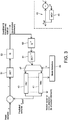
Figure 3 is a high-level block diagram schematically illustrating an encoder such as might be implemented on transmittingterminal 12. The encoder comprises: a discrete cosine transform (DCT)module 51, aquantizer 53, aninverse transform module 61, aninverse quantizer 63, anintra prediction module 41, aninter prediction module 43, and a subtraction stage (-). The encoder also comprises aswitch 47 andmode selection module 49. Each of the modules is preferably implemented as a portion of code stored on the transmitting terminal'sstorage medium 14 and arranged for execution on itsprocessing apparatus 16, though the possibility of some or all of these being wholly or partially implemented in dedicated hardware circuitry is not excluded. - Each of the
switch 47 andmode selection module 49 is arranged to receive an instance of the input video stream comprising a plurality of macroblocks MB. Themode selection module 49 is arranged to select a coding mode "o" for each macroblock and is operatively coupled to themultiplexer 47 so as to control it to pass the output of theinverse quantizer 63 to the input of either theintra prediction module 41 orinter prediction module 43 as appropriate to the selected mode. Themode selection module 49 may also be arranged to indicate the selected mode "o" to therelevant prediction module 41, 43 (e.g., to indicate a 4x4 partition mode, 8x8 mode, skip mode, etc), and to receive information fed back from theprediction module intra prediction module 41 orinter prediction module 43 is then coupled on to an input of the subtraction stage (-) which is arranged to receive the unencoded input video stream at its other input and subtract the predicted blocks from their unencoded counterparts, thus generating the residual signal. The residual blocks are then passed through the transform (DCT)module 51 where their residual values are converted into the frequency domain, then to thequantizer 53 where the transformed values are converted to discrete quantization indices. The quantized, transformed signal is fed back though theinverse quantizer 63 andinverse transform module 61 to generate a predicted version of the blocks or subblocks (as would be seen at the decoder) for use by theselected prediction module prediction modules inter prediction module 43 and the quantized, transformed indices of the residual as generated by the transform andquantization modules - According to the above, a coding representation may thus include block partition information, prediction mode, motion vector, quantization accuracy, etc. The optimal coding option depends on video content, bit rate, earlier coding decisions, etc. The accuracy of quantization of transform coefficients is typically chosen to meet a bit rate constraint. Furthermore, distortion should be minimized.
- For example, the H.264 video coder provides a great flexibility in choosing the prediction mode [1]. For inter prediction of the luma component, a macroblock of 16x16 pixels can be represented as one block of 16x16 pixels, or two blocks of 16x8 pixels, or two blocks of 8x16 pixels, or four blocks of 8x8 pixels. Further, an 8x8 block can be represented as one block of 8x8 pixels, or two subblocks of 8x4 pixels, or two subblocks 4x8 pixels, or four subblocks of 4x4 pixels. The inter prediction is tried for each allowed partition of a macroblock. The inter prediction of a block is represented by indexing the reference frame(s) and the motion vector(s) (spatial shift from the reference block in the respective reference frame), which typically are estimated with sub-pixel precision. For intra prediction of the luma component, there are four possible modes for 16x16 blocks and nine possible modes for 4x4 subblocks. Further, there are four possible modes for chroma components. The best prediction mode is chosen by comparing the performance of inter and intra prediction modes.
- The rate-distortion performance of a video codec such as H.264 AVC [1] depends to a large extent on the performance of the macroblock mode selection o. That is, the procedure of determining whether the macroblock is best encoded, in terms of rate-distortion trade-offs, using e.g., intra mode or inter mode. From a robustness perspective, intra coded macroblocks are beneficial since they stop temporal error propagation (assuming the use of constrained intra prediction, i.e., intra prediction from inter predicted macroblocks is prohibited). However, intra coded macroblocks are generally more expensive in terms of rate compared to inter coded macroblocks, and thus it is important to introduce intra coded macroblocks systematically such that the distortion (e.g., average distortion) at the decoder is minimized given a certain bit budget and channel condition. Zhang et al [2] propose such a systematic framework to introduce intra coded macroblocks based on the minimization of the expected average sum of squared differences (SSD) at the decoder. By tracking the potential distortion Zhang et al are able to compute a bias term related to the expected error-propagation distortion (at the decoder) that is added to the source coding distortion when computing the cost for inter macroblocks within the encoder rate-distortion loop.
- The rate-distortion performance optimization problem can be formulated in terms of minimizing distortion under a bit rate constraint R. A Lagrangian optimization framework is often used to solve the problem, according to which the optimization criterion may be formulated as:

- In this application solving the Lagrangian optimization problem means finding the encoding mode o which minimizes the Lagrange function J, where the Lagrange function J comprises at least a term representing distortion, a term representing bitrate, and a factor (the "Lagrange multiplier") representing a tradeoff between the two. As the encoding mode o is varied towards more thorough or better quality encoding modes then the distortion term D will decrease. However, at the same time the rate term R will increase, and at a certain point dependent on λ the increase in R will outweigh the decrease in D. Hence the expression J will have some minimum value, and the encoding mode o at which this occurs is considered the optimal encoding mode.
- In this sense the bitrate R, or rather the term λR, places a constraint on the optimization in that this term pulls the optimal encoding mode back from ever increasing quality. The mode at which this optimal balance is found will depend on λ, and hence λ may be considered to represent a tradeoff between bitrate and distortion.
- The Lagrangian optimization is commonly used in the process of choosing coding decisions, and is applied for every frame region (e.g., every macroblock of 16x16 pixels). Commonly, the distortion may be evaluated to account for all processing stages. These include prediction, transform, and quantization. Furthermore, in order to compute reconstructed pixels, steps of inverse quantization, inverse transform, and inverse prediction must be performed. SSD is often preferred as distortion criterion since it results in higher quality compared to SAD. Commonly, the rate also accounts for coding of all needed parameters, including parameters describing prediction and quantized transform coefficients [4].
- In [2] Zhang et al, the authors estimate the potential distortion in the decoder due not only to source coding but also to channel errors, i.e., also a likely distortion that would be experienced due to loss of data when the signal is transmitted over the channel. The estimated potential distortion is then indirectly used to bias the mode selection towards intra coding (if there is a probability of channel errors).
- Zhang's "end-to-end" distortion expression is based on the sum of squared differences (SSD) distortion measure and assumes a Bernoulli distribution for losing macroblocks. The optimal macroblock mode oopt is given by:

- In [2] the term D ep_ref (m,o) follows the motion of the objects and is calculated from a total distortion map using the current motion vectors. The total expected error propagation distortion map Dep is driven by the performance of the error concealment and is updated after each macroblock mode selection as:

- In [2] Dep is stored on a 4x4 grid over each macroblock of the frame, i.e. 16 values of Dep per macroblock, so one value of Dep per 4x4 pixel subblock of each macroblock. As shown in
Figure 1c , the computation of D ep_ref (m(k),o), i.e. the expected error-propagation reference distortion for a subblock k within the macroblock m of frame at time n, is then performed as a weighted sum of the values of Dep from four subblocks from a preceding frame from time n-1. The weights are determined from the motion vector for the block m in question. That is:
-
Figure 1c provides an illustration of the computation of the expected error-propagation reference distortion from a motion vector and an expected error-propagation distortion map, with reference to exemplary subblocks b1 ...b4 (in this example k corresponds to b1 and i counts through b1...b4). -
US 2008/0247469 A1 discloses a method of refreshing a macroblock (MB) by coding the MB as an inter MB with respect to a reliable reference frame. The selection of the MBs to refresh is based on the error propagation metrics evaluated over those MBs. The decision to code a refresh MB as an inter MB (with respect to an RRF) or an intra MB is done by evaluating a suitable cost function for each mode and choosing the mode with the lower cost. - Zhang et al., "Optimum end-to-end distortion estimation for error resilient video coding", Electronic Publishing, Artistic Imaging, and Digital Typography; [Lecture Notes in Computer Science, ISSN 0302-9743] discloses an end-to-end distortion estimation scheme where the correlations of the potentially propagated errors of the different frames are modelled based on theoretical analysis.
- In WIEGAND T ET AL: "Error-resilient video transmission using long-term memory motion-compensated prediction" [IEEE JOURNAL ON SELECTED AREAS IN COMMUNICATIONS, IEEE SERVICE CENTER, PISCATAWAY, US, vol. 18, no. 6, 1 June 2000 (2000-06-01), pages 1050-1062, XP011450023] various experimental results are reported regarding a simplified error modelling in combination with decoder feedback for the purpose of motion compensated predictor selection in a video encoder using multiple reference frames. For erroneously received image portions notified by the decoder, the encoder adjusts the affected frames in the reference picture buffer through error concealment operations identical to those performed by the decoder.
- The process of Zhang et al [2] is based only on a priori probabilistic assumptions made purely at the encoder about the likelihood of loss over the channel.
- However, some existing communication systems provide a feedback mechanism for the purpose of reporting certain information back from the receiver to the transmitter, and/or for control purposes. For example the encoder may receive back information about what frames arrived correctly at the decoder and/or what frames that were lost in the transmission, and in response may generate an intra frame to break error propagation. However the existing mechanism is simplistic in that it only triggers the generation of a whole intra frame, and also does not incorporate any probabilistic estimate of distortion that is likely to be experienced due to loss of other frames or parts of frames that are yet to be either acknowledged or reported lost.
- The algorithm by Zhang et al [2] considers only the scenario of transmitting video over an erroneous channel without considering the possible use or availability of any feedback, and as such the process of Zhang is not based on any actual a posteriori knowledge of the channel.
- Viewed from the other perspective, the conventional use of the feedback only triggers generation of a whole intra frame, and there is no mode selection at a level of individual portions within a frame (e.g. macroblock by macroblock). Also, the conventional use of feedback does not involve an estimate of a distortion that would be experienced due to possible loss over the channel.
- The inventors on the other hand propose to make use of information being fed back from the decoder to the encoder, e.g. the packet and/or frame arrival status, to further adapt the loss-adaptive rate-distortion optimization process in the encoder and thereby improve the overall rate-distortion performance compared to the method by Zhang et al. [2]. The following paragraphs of this section refer to various "embodiments" and "variants" of the invention only for illustrative purposes of certain general concepts underlying the present disclosure. These are not to be confused with embodiments of the protected invention, which are required to comprise all of the technical features defined in the appended independent claims.
- A first embodiment of the present invention may make use of a system of short- and long-term references. For example, the H.264 AVC standard supports a functionality of marking certain reference frames as so-called "long-term" references. These long-term references remain in the decoded picture buffer until explicitly removed. This is in contrast to the "short-term" reference frames where a new short-term reference overwrites the oldest short-term reference frame in the decoded picture buffer.
- According to the first embodiment of the present invention, the feedback mechanism can be used to make the encoder aware of what is the latest acknowledged long-term reference available at the decoder (in addition to information about which frames have been lost). In the following, an acknowledged reference preferably means an acknowledged error-free reference (i.e. a reference without any error-propagation distortion), rather than just a reference that is acknowledged in itself. That is, the references should preferably be acknowledged according to a strict definition that the reference is acknowledged as received and everything relevant in that reference's history was also acknowledged as received, so that it can be known there is no error propagation; as opposed to it just being acknowledged that the current reference is received without strict acknowledgement of its history. Note that a portion in a frame that is only acknowledged in itself, but which is encoded relative to error-free blocks, is also error-free (no propagation error).
- Inter prediction based on acknowledged long-term reference frames can be used to stop error propagation in the decoder, similar to intra coding. The benefit of using inter prediction from a long-term reference is that inter prediction generally results in a lower bitrate for a given distortion level.
- By utilizing the acknowledged long-term references for inter prediction, this first embodiment of the present invention makes available an additional macroblock coding mode, to be used for example in the framework of Zhang [2], that can stop error propagation similar to intra coding, but in general at a lower associated bitrate.
- The algorithm by Zhang et al [2] considers only two different types of coding mode, intra and inter coding. In that case the error-propagation reference distortion Dep-ref (m,o) in equation (3) is zero only for intra coded macroblock modes . However, the first embodiment of the present invention augments the set of available coding modes to include inter coding from acknowledged long-term references. Dep-ref (m,o) is then set to zero not only for intra coding but also for inter coding from acknowledged references. The advantage of such a coding mode is that it can stop the error propagation in a similar manner to intra coding, but at a lower bitrate in general.
- A variant of the first embodiment of the present invention uses the idea that, for a certain reference (e.g. long-term reference) for which no feedback has yet be received, this reference nonetheless has a certain probability of becoming an error-free acknowledged reference based on intermediate reports from the decoder. For example, yet another available encoding mode may be introduced which distinguishes the use of inter prediction based on a non-acknowledged long-term reference from the use of inter prediction based on a non-acknowledged short term reference. For the non-acknowledged long-term reference, the estimate of error propagation distortion Dep-ref(m,o) is reduced in dependence on the a priori estimate of the probability of loss (i.e. p is not in itself based on feedback), and based on the time (or equivalently number of frames) since the last (most recent) acknowledged long-term reference in the non-acknowledged reference's history.
- In another variant of the first embodiment, when the round-trip time (RTT) for a packet is sufficiently low compared to the number of short-term references in the decoded picture buffer (the round-trip time is the time for a packet to travel from the transmitter to the receiver and back again), then the same concept may apply to short-term references. That is, for a sufficiently small RTT, an alternative or additional possibility is to recognize short-term references as being acknowledged, which can then be used in a similar way to the acknowledged long-term references discussed above. Again, the required algorithmic change to equation (3) is that Dep-ref (m,o) is set to zero not only for intra coding but also for inter coding from acknowledged references.
- Also, note that the acknowledgements need not be on a whole-frame basis. It may instead be arranged to receive acknowledgements for only parts of frames, e.g. slices, and treat those different parts differently in dependence on the acknowledgement or lack thereof (or explicit report of non receipt).
- In a second embodiment of the present invention, information fed back from the decoder to the encoder such as the packet and/or frame arrival status is used to adjust the potential distortion maps in the encoder, and thereby improve the overall rate-distortion performance compared to the method by Zhang et al.
- According to the second embodiment, the potential error propagation distortion maps are stored in association with each frame or slice in the decoded picture buffer of the encoder (together with error concealment reconstruction distortion maps, error concealment error propagation maps, corresponding mode decisions and motion vector information). This second embodiment then utilizes the feedback information from the decoder to update the potential distortion maps. The feedback information facilitates refined potential distortion tracking, yielding better rate-distortion performance.
- If the encoder receives feedback information signaling that a particular frame has arrived at the decoder, the error concealment contributions can be removed from the error propagation distortion map in equation (3). Conversely, if feedback information is received signaling that a particular frame or slice was lost at the decoder, the associated error propagation distortion map is recomputed so as to only include the contributions from the error concealment distortion, i.e. the second and third term in the right hand side of equation (3) (normalized with p).
- Then, if the round trip time (RTT) is small in comparison to the number of reference pictures in the decoded picture buffer, it is possible to propagate the adjusted potential error-propagation map at time n-RTT to the error propagation distortion map at time n-1 using equation (3) recursively. The updated error propagation distortion map at time n-1 will then be the basis for the computation of the Dep_ref at time n which is used in the mode selection process (2). This results in a more accurate tracking of the potential distortion maps, and thus, improves the overall rate-distortion performance of the system.
- The above outlines some particular exemplary embodiments, to aid understanding the functioning of the invention, but it is emphasized again that any embodiment of the protected invention is to be seen as restricted in scope to a system, computer program product and apparatus in line with the combinations of technical features defined, respectively, in the appended independent claims.
- For a better understanding of the present invention and to show how it may be put into effect, reference is made by way of example to the accompanying drawings in which:
-
Figure 1a is a schematic representation of a video stream, -
Figure 1b is a schematic representation of some intra prediction coding modes, -
Figure 1c is a schematic representation of a calculation of error propagation distortion, -
Figure 2 is a schematic block diagram of a communication system, -
Figure 3 , is a schematic block diagram of an encoder, and -
Figure 4 is a schematic block diagram of a system employing feedback from a decoder to an encoder. - The following describes an encoding system and method which make use of information being fed back from the decoder to the encoder, e.g., the packet and/or frame arrival status, in order to further adapt the loss-adaptive rate-distortion optimization process and thereby improve the overall rate-distortion performance. The encoder is similar to that described in relation to
Figure 3 , but with a modifiedmode selection module 49. It may be used to encode a video stream of the kind illustrated inFigure1 , and implemented in a communication system such as that ofFigure 2 . - As mentioned, mode selection may involve optimizing (e.g., minimizing) a Lagrangian type function:

- In a conventional case the distortion term D only takes into account the source coding distortion, i.e., due to imperfections in the encoder such as the distortion introduced by quantization. It does not take into account the distortion that may be introduced due to loss of data over the channel, e.g., due to packet loss in transmission over a packet-based
network 32. - On the other hand, loss adaptive techniques such as those of the present invention and Zhang [2] attempt to define a measure of "end-to-end" distortion taking into account both the source encoding and the distortion due to loss of data over the channel. The end-to-end distortion for a given (target) block, macroblock or subblock may be described as:

network 32. The parameter p is an estimate of the probability of a loss event occurring over the channel that results in the block or image portion in question being lost, e.g., an estimate of the probability of a packet loss. For convenience the term "block" may be used in places here to refer generally to the relevant level of frame partition (e.g., a block or subblock of certain standards such as H.264). - Darrival represents not only the source coding distortion but also the distortion that will be introduced due to distortion of a block's past, i.e., distortion in one or more reference blocks from which the target block is to be predicted. Therefore Darrival comprises both a source coding distortion term Ds and an error propagation distortion term Def_ref which represents a distortion in the predicted target block's history (i.e., distortion in the target blocks' reference block which will carry forward into the target block):

- Dloss comprises a loss due to concealment. If a target block is not received then the decoder will apply a concealment algorithm which could involve freezing a previously decoded block, or interpolating or extrapolating from one or more successfully decoded blocks (either from the current frame and/or a previous frame). Therefore Dloss can be identified as the distortion due to this concealment process:

- So examining equation (5), the term Ds represents an estimate of the distortion that will be experienced if there is no loss at all, the term Dec represents an estimate of the distortion that will be experienced if the target block is lost, and the term Dep_ref represents an estimate of the distortion that will be experienced if the target block is successfully received but something in its history is lost (if the target block's reference block is lost, or the reference block's reference block is lost, etc.)
- Ds and Dep_ref are functions of encoding mode selection o. Dec is not a function of mode selection o and so is dropped from the Lagrange expression (it does not matter how a lost block was encoded - it is still lost). Hence the optimization can be written as:

- Ds is deterministic as it is based on information that can be known at the encoder, for example based on the difference between the raw input sample values s and the reconstructed sample values ŝ. The encoder runs a parallel instance of the decoder at the encoder side (or an approximation of it) - see the inset detailing the
inter prediction module 43 inFigure 3 . Theinter prediction module 43 comprises a motion compensation prediction (MCP)block 44 and addition stage (+) arranged to determine the reconstructed samples ŝ by combining the predicted samples ŝpred and the reconstructed residual r̂, i.e., ŝi = r̂i + ŝpred for each sample index i. - In the case of inter encoding, at the encoder the predicted samples ŝpred may be the same as the samples of the reference block ŝref (the reference block in the reference frame just being offset by the motion vector relative to the target frame - see
Figure 1c , to be discussed again shortly). - Hence the encoder can determine the difference between the actual samples s and the reconstructed samples ŝ as seen at the encoder and decoder end (this so far ignores the possibility of loss which will introduce further distortion experienced at the decoder). The difference in samples may be calculated for example as the sum square difference (SSD) error over all sample indices i of the target block in question:

- However, Dep_ref remains to be estimated, which will be based on making some estimation concerning the channel over which the encoded data is to be transmitted (e.g., over packet-based network 32).
- To achieve this, the
mode selection module 49 in the encoder may be configured to maintain an error propagation distortion map Dep describing the distortion of each macroblock or partition of a macroblock within the most recently encoded frame. Themode selection module 49 is also arranged to determine a probability p that the packet containing the reference block from which a target block is to be predicted will be lost over the channel (and therefore also to implicitly or explicitly determine a probability 1-p that the packet does arrive). The probability p may be predetermined at the design stage based on statistical modelling, in which case themode selection module 49 determines p by retrieving a value frommemory 14. However, another possibility would be that themode selection module 49 determines p based on feedback from the receiver 22. - The error propagation map may be expressed as:

- The error propagation map Dep comprises a distortion estimate for macroblock m or more preferably for each sub partition (block or sub-block) m(k) within the most recently encoded frame. Hence it may be more explicitly written as:

- Dloss is equal to Dec as discussed above. Dep_arrival represents the differences over the channel, i.e., the difference between the reconstructed samples at the encoder and the reconstructed at the decoder. For example this could be quantified in terms of the sum of squared differences (SSD):

- Dep_arrival can be expanded to:


- So substituting into equation (9), the error propagation map can be rewritten as:


- Considering the mode optimization problem, it may also be written:

- As in Zhang [2], the Dec term may be also expanded:

- Examining equation (3), as explained above, the term Dep_ref represents the distortion that will be experienced if the target block is successfully received but something in its history is lost (if the target block's reference block is lost, or the reference block's reference block is lost, etc.). Further, Dec-rec represents an estimate of the distortion due to the nature of the concealment algorithm itself (somewhat analogous to the intrinsic source coding distortion Ds for prediction). D ec-ep then represents an estimate of the distortion that will be experienced if both the target block is lost (and so needs to be concealed at the decoder) and something in the concealed target block's history is lost (if the block from which concealment is done is lost, or the block from which that block is predicted or concealed is lost, etc.).
- So the distortion map Dep comprises a contribution due to new loss, resulting from Dec-rec and in part from Dec-ep ; and a contribution due to past loss, resulting from Dep_ref and in part also from Dec-ep.
- For the first frame in a sequence the frame will be coded with intra coding, in which case Depref = 0 and therefore Dep = pDec.
- The error concealment distortion Dec is calculated by the
mode selection module 49. The term Dec-rec is based on knowledge of the concealment algorithm, and may depend on the particular error concealment algorithm used. D ec-ep is calculated based on the existing (most recent) distortion map in a manner analogous to Dep_ref, e.g., by copying the distortion of a co-located block in the case of a basic concealment algorithm or calculating a weighted sum of the distortions from multiple previously encoded blocks b1-b4 if a more complex concealment is used that attempts to extrapolate motion (by analogy see discussion in relation toFigure 1c below). Other ways of calculating Dec could be used - this could be any estimation of a difference between the reconstructed samples in the encoder and the error concealed samples as would be seen ay the decoder (i.e., the samples copied, interpolated or extrapolated from a previous received frame or a received region of the same frame to conceal the lost frame or region). - The
mode selection module 49 then maintains the error propagation map for each subsequent inter predicted frame by updating it following each mode selection decision, now including a calculation of Dep_ref from knowledge of the existing error map. In the case of inter prediction (motion estimation), according to Zhang [2] this is done using the motion vectors for the frame in question. - An example of this is illustrated in
Figure 1c . Four example blocks b1, b2, b3 and b4 are shown in a reference frame Fn (at time n-1), the reference frame having already been encoded. The blocks of the target frame Fn (at a subsequent time n) are to be predicted from the reference frame Fn-1. For example consider a target block b1 in the target frame Fn. To this end themotion prediction module 44 determines a motion vector defining an offset between the target block in the target frame Fn and a reference block (shown by the dotted line) in the reference frame Fn-1, such that when the reference block is translated from the offset position in the reference frame Fn-1 into the position of the target block b1' in the target frame Fn it provides a best estimate of the target block b1. Note therefore that the dotted reference block is not necessarily an indexable block in the reference frame Fn-1, i.e., is not necessarily a predetermined subdivision of the reference frame, and may be offset by any arbitrary amount (and in fact may even be offset by a fractional number of pixels). Hence the reference block is made up of a contribution from four actual indexable blocks b1, b2, b3 and b4. - Accordingly, the existing calculation performed by the
mode selection module 49 to determine Dep_ref for use in the update of the error propagation map Dep(n+1) comprises calculating a weighted sum of the distortions recorded for blocks or subblocks b1 to b4 in the existing map Dep(n):
- Or more explicitly:

- The above describes an existing process of determining an initial error propagation map Dep, using the error propagation map to select an optimal coding mode decision oopt for a subsequent coding, using the coding decision to update the map Dep, then using the updated map in the next coding decision, and so forth, wherein the error propagation map represents an end-to-end distortion including an estimated effect of loss over the channel. E.g., reference is made again to Zhang [2]. This may be referred to herein as loss-adaptive rate-distortion optimization (LARDO).
- However, the process of Zhang et al [2] is based only on a priori probabilistic assumptions made purely at the encoder about the likelihood of loss over the channel.
- The present invention provides an improvement over Zhang by making make use of information being fed back from the decoder to the encoder, e.g., the packet and/or frame arrival status, to further adapt the loss-adaptive rate-distortion optimization process in the encoder and thereby improve the overall rate-distortion performance.
-
Figure 4 is a schematic block diagram depicting a system of encoder and decoder that may be used to implement the present invention. Preferably the encoder is manifested in thestorage 14 andprocessing apparatus 16 of the transmittingterminal 12, and the decoder is manifested in thestorage medium 24 andprocessing apparatus 26 of the receiving terminal 22. The encoder on the transmittingterminal 12 comprises an encoding module and an encoder-side instance of a decoding module mirroring or approximating the decoding as performed at the decoder. The encoding module comprises theforward transform module 51 andquantizer 53, as well as potentially one or more other stages such as an entropy encoder (not shown). The encoder-side decoding module comprises theinverse quantizer 63 andinverse transform module 61, as well as potentially other stages such as an entropy decoder. The encoder also comprises the motion compensation prediction (MCP)module 44, and subtraction stage (-). Reference is made again toFigure 3 for an explanation of the connections between these encoder elements. - Furthermore, not shown in
Figure 3 is that the encoder also comprises a decodedpicture buffer 65 connected in the path between the encoder-side decoding module compensation prediction module 44. The decodedpicture buffer 65 comprises a plurality of constituent buffer regions each of which may be marked as holding either a short-term reference or a long-term reference. In H.264 there is only one actual buffer in which markers are used to indicate long-term references (but the possibility of separate, dedicated short and long term buffers in other implementations is not excluded). InFigure 4 the decodedpicture buffer 65 is shown as holding one or more short-term references 66, one or more unacknowledged long-term references 67, and one or more acknowledged long-term references 68. - Each constituent buffer region is operable to store a reconstructed version of one or more previously encoded frames or slices (i.e., having been encoded and then decoded again by the encoder-side instance of the
decoding module - The decoded
picture buffer 65 is arranged such that a short-term reference 66 is automatically updated with each successive frame or slice that is encoded. I.e., as each frame or slice is encoded, then the decoded version of that new frame or slice automatically overwrites another recent reference frame or slice that was previously held in the short-term buffer. In preferred embodiments the decodedpicture buffer 65 can hold multiple short-term references 66 and the oldest short-term reference is always the reference that is overwritten in the buffer. No additional condition is required for this to happen. - As mentioned, the H.264 AVC standard also allows certain reference frames or slices to be marked as long-
term references - The decoder on the receiving
terminal 24 comprises decoder-side instances 44', 61', 63', 65', 66', 67' and 68' of the motioncompensation prediction module 44,decoding module picture buffer 65 arranged to store corresponding short and long term references 66, 67 and 68. - The decoder on the receiving
terminal 24 is configured to communicate with the encoder on the transmittingterminal 12 via a feedback channel. The feedback is preferably via thesame network 32 by which the video stream is transmitted to the receiving terminal 22, e.g., the same packet-based network such as the Internet, though the possibility of an alternative feedback mechanism is not excluded. - By way of example, the long-term references may be managed by the controller as follows. Say it is decided to maintain two long-term references in the decoded picture buffer (e.g., It pos 0 and It pos 1). The first frame (at a time t0) that is encoded may be placed into It pos 0. It may be assumed that the first frame will arrive at the decoder (the feedback from the decoder will arrive after one RTT) and therefore It pos 0 is initially marked as error-free acknowledged. The next frame marked as a long-term reference is the frame at time t0+RTT, which is placed at It pos 1. If the encoder gets the feedback from the decoder indicating that the reference at It pos 1 arrived (and contained no error propagation) then It pos 1 is marked as error-free acknowledged and the next long-term reference frame (at time t0 + 2*RTT) is placed into It pos 0. Thus, the two positions form a ping-pong buffer where there's always one position that is error-free acknowledged and one position that is used temporarily for probing. This way there should always be a fairly recent acknowledged error-free reference in the decoded picture buffer that can be used to generate a recovery frame from in case of a loss. In principle, the closer the It-ref frame is to the current time position the more efficient is the inter coding, and thus, the smaller (in bits) the recovery frame will be. However, this is only one strategy the encoder's controller may be configured to use to manage long-term references, described for the sake of example, and it will be appreciated that other ways of managing a system of long- and short-term references in a picture buffer are possible (e.g., an even better way is to provide more It-refs).
- With reference to the exemplary implementation of
Figure 4 , the present invention considers the feedback to contain information about the decoded picture buffer 65' at the decoder. Given this feedback the encoder knows for example which frames or slices in the decoder were decoded without containing any error-propagation distortions. InFigure 4 theentry 68 in the decodedpicture buffer 65 refers to such an acknowledged error-free frame. Theentry 67 in the decodedpicture buffer 65 refers to an unacknowledged frame. The feedback mechanism can be used to make the encoder aware of what is the latest acknowledged long-term reference available at the decoder (in addition to information about which frames have been lost). In the following, an acknowledged reference preferably means an acknowledged error-free reference (i.e., a reference without any error-propagation distortion), rather than just a reference that is acknowledged in itself. That is, the references should preferably be acknowledged according to a strict definition that the reference is acknowledged as received and everything relevant in that reference's history was also acknowledged as received, so that it can be known there is no error propagation; as opposed to it just being acknowledged that the current reference is received without strict acknowledgement of its history. Note that a portion in a frame that is only acknowledged in itself, but which is encoded relative to error-free blocks, is also error-free (no propagation error). - According to a first embodiment of the present invention, inter prediction based on acknowledged long-term reference frames (or slices) can be used to stop error propagation in the decoder in a similar manner to intra coding. The benefit of using inter prediction from a long-term reference is that inter prediction generally results in a lower bitrate for a given distortion level.
- By using the acknowledged long-term references for inter prediction, the first embodiment of the present invention makes available an additional macroblock coding mode, to be used for example within the framework of Zhang [2], that can stop error propagation similar to intra coding, but in general at a lower associated bitrate.
- The algorithm by Zhang et al [2] considers only two different types of coding mode, intra and inter coding. In that case the error-propagation reference distortion Dep-ref(m,o) is zero only for the intra coded macroblock modes in equation (3). However, the first embodiment of the present invention augments the set of available coding modes to include inter coding from acknowledged long-term references. The advantage of such a coding mode is that it can stop the error propagation in a similar manner to intra coding, but at a lower bitrate in general.
- The required change to the algorithm presented above is that the error-propagation reference distortion in equations (2) and (3) is set to zero also when the coding mode is inter encoding from an acknowledged reference frame, i.e.:

- In certain variants of the first embodiment, the above example can be modified in the following way. Consider the scenario where the encoder marks, at e.g., a regular spacing dependent on the round trip time (RTT), a reference frame as a long-term reference. Thus, the decoded picture buffer 65 (as shown in
Figure 4 ) will at some time instance contain a short-term reference 66, a "non-acknowledged" long-term reference 67, and an acknowledged long-term reference 68. For the "non-acknowledged" long-term reference 67 to become acknowledged at the decoder according to a strict definition, it would be required that there are no losses prior to the non-acknowledged long-term reference, i.e., that the acknowledged long-term reference is a decoded frame without any error-propagation distortion. At the encoder side feedback is received conveying information as to what frames have been received by the decoder. Given that the encoder knows exactly what frames were marked as (non-acknowledged) long-term references and has an estimate p of the packet or frame loss probability, it is possible to setup a model for the probability that the non-acknowledged long-term reference will convert into an acknowledged long-term reference. If the frame loss probability is p and there is a known or predetermined interval L between two long-term references, then the a priori probability that the non-acknowledged long-term reference will become acknowledged is (1-p)L. Gradually, as positive feedback information is received, e.g., the decoder has received l out of the L frames so far, the probability that the long term reference will be acknowledged change from (1-p)L to (1-p)(L-l). The described probability model can now be used to generalize the equations for Dep-ref(m,o) above as:
- Thus this variant of the first embodiment introduces yet another encoding mode which distinguishes the use of inter prediction based on a non-acknowledged long-term reference from the use of inter prediction based on a non-acknowledged short term reference. For a certain long-term reference for which no feedback has yet be received, this nonetheless has a certain probability of becoming an error-free acknowledged reference based on intermediate reports from the decoder. For the non-acknowledged long-term reference, the estimate of error propagation distortion Dep-ref(m,o) may therefore be weighted in dependence on the a priori estimate of the probability of loss (i.e., p is not in itself based on feedback), and based on the time (or equivalently number of frames) since the last (most recent) acknowledged long-term reference in the non-acknowledged reference's history. The weight attenuates the estimate of distortion, so as to reduce or dampen the estimate.
- It may be noted that the above logic is just an example embodiment and in the form above is somewhat conservative in that it assumes that all losses have an impact on the frame marked as long-term reference. The logic above can be refined so as to only take into account losses of frames or slices affecting the long-term reference frame.
- In yet another generalization, consider the case where the long-term reference has been received by the decoder, but there were losses prior to the long-term reference. Thus, the long-term reference is not "acknowledged" according to the strict definition above. However, if the mode decisions have been stored for all the macroblocks of the frame, the parts where the corresponding mode was set to intra or acknowledged long-term reference are then associated with zero error-propagation reference distortion, and thus inter-prediction referenced from those regions break error propagation at a potentially lower rate-distortion cost compared to intra coding.
- Although the example embodiments above are all based on the concept of long-term references and feedback reporting, the same concept may apply to short-term references when the round-trip time (RTT) is sufficiently low compared to the number of short-term references in the decoded picture buffer. That is, for a sufficiently small RTT, an alternative or additional possibility is to recognize short-term references as being acknowledged, which can then be used in a similar way to the acknowledged long-term references discussed above. The required algorithmic change to equation (3) in the previous section is that Dep-ref(m,o) is set to zero not only for intra coding but also for inter coding from acknowledged references.
- The generalizations to the first embodiment discussed above improve the flexibility in making trade-offs between robustness and source coding.
- On an additional point, LARDO per default assumes constrained intra prediction, i.e., intra prediction from inter predicted macroblocks is prohibited. However, the inventors have observed that constrained intra prediction can in fact cause severe coding distortions (especially on smooth gradient picture areas). Therefore, in a particularly preferred variant of the present invention, LARDO should be run without constrained intra prediction. The implication is that the intra coding mode (when predicted from an inter-predicted macroblock) is also associated with an error-propagation reference distortion, and thus, the only mode that is not associated with an error-propagation reference distortion is inter prediction from acknowledged error-free reference pictures.
- In a second embodiment of the present invention, information fed back from the decoder to the encoder such as the packet and/or frame arrival status is used to adjust the potential distortion maps in the encoder, and thereby improve the overall rate-distortion performance compared to the method by Zhang et al.
- According to the second embodiment, the error propagation distortion map Dep for each frame or slice of a frame is stored in association with that frame or slice in the decoded
picture buffer 65 of the encoder. For each frame or slice, the decodedpicture buffer 65 at the encoder also stores the corresponding error concealment reconstruction distortion map Dec-rec, error concealment error propagation map Dec-ep, corresponding mode decisions o and motion vector information. The feedback information from the decoder is then used by the encoder to update the distortion maps. Refer again to equation (3). The feedback information allows the estimated distortion tracking to be refined, yielding better rate-distortion performance. - Preferably this is achieved as follows. If the encoder receives feedback information signaling that a particular frame or slice has successfully arrived at the decoder, the error concealment contributions Dec-rec and D ec-ep can be removed from the error propagation distortion map Dep in equation (3). Conversely, if feedback information is received signaling that a particular frame or slice was lost at the decoder, the associated error propagation distortion map Dep is recomputed so as to only include the contributions from the error concealment distortion, i.e., the second and third term in the right hand side of equation (3), Dec-rec and D ec-ep (normalized by the a priori loss probability estimate p).
- Then, if the round trip time (RTT) is small in comparison to the number of reference pictures in the decoded picture buffer, it is possible to propagate the adjusted potential error-propagation map Dep at time n-RTT to the error propagation distortion map at time n-1 by applying equation (3) recursively. The updated error propagation distortion map Dep at time n-1 will then be the basis for the computation of the Dep_ref at time n which is used in the mode selection process (2). This results in a more accurate tracking of the potential distortion maps, and thus, improves the overall rate-distortion performance of the system.
- It will be appreciated that the above embodiments have been described only by way of example.
- Generally, while the above has been described in terms of slices, macroblocks and blocks or sub-blocks, these terms are not necessarily intended to be limiting and the ideas described herein are not limited to any particular way of dividing or subdividing a frame. Further, the distortion map may cover a whole frame or a region within a frame, and coding decision process may be applied over the whole frame or only for a region within a frame. Note also that the prediction block granularities do not have to be the same as or even connected to the distortion map granularity (though that possibility is not excluded).
- The sum of squared differences (SSD) is often preferred as measure of difference since it results in higher quality compared to sum of absolute differences (SAD), but the latter possibility or other possibilities are not excluded and generally the invention could be implemented using any measure of difference between samples as a basis for quantifying distortion.
- Commonly, the measure of rate also accounts for coding of all needed parameters, including parameters describing prediction and quantized transform coefficients. This kind of optimization may be referred to herein as full rate-distortion optimization (RDO). In lower complexity embodiments however, the distortion and/or rate term may be approximated by only taking into account the effect of some but not all processing stages, e.g., only taking into account the effect of prediction.
- Further, where the present invention is described in terms of two frames n-1 and n, or n and n+1 or such like, according to certain embodiments of the invention it is not necessary for these to refer to two adjacent frames (though that may be the case in existing codecs). In some embodiments it is possible that inter prediction could be performed relative to an even earlier frame, and as such n-1 and n, or n and n+1, may be used in relation to the present invention to refer respectively to any previously encoded frame or image portion and a subsequent frame or portion to be predicted from it.
- Note again that where a contribution due to loss is mentioned in this application, or anything stating what happens "if" data lost over the channel or such like, this only relates to a probabilistic assumption (e.g., p) made by the encoder about what might be experienced by the decoder - the encoder of course does not know what will happen. The probabilistic assumption may be predetermined at the design stage based on statistical network modelling, and/or could even be determined dynamically based on feedback from the decoder.
- Other variants may become apparent to a person skilled in the art given the disclosure herein. The scope of the invention is not limited by the described embodiments but only by the appendant claims.
Claims (6)
- A method of encoding a video stream at an encoder of a transmitting terminal for transmission over a lossy channel to a decoder at a receiving terminal, the method comprising:performing a rate-distortion optimization process comprising, for each of a plurality of target image portions to be encoded in each of a plurality of frames, selecting a preferred one of a set of encoding modes by optimizing a function comprising an estimate of distortion for the target image portion and a measure of bit rate required to encode the target image portion, wherein the estimate of distortion is based on source coding distortion and an estimate of a distortion that would be experienced due to possible loss over the channel, wherein the estimate of distortion that would be experienced due to possible loss is based on a first contribution representing an estimate of the distortion that would be experienced, if the target portion does arrive over the channel, due to non-arrival of a reference portion in the target portion's history from which prediction of the target portion depends, and on a second contribution representing an estimate of distortion that would be experienced due to concealment which comprises a contribution representing a measure of concealment distortion of the target portion relative to an image portion that would be used to conceal loss of the target portion if the target portion is lost over the channel, and a contribution representing an estimate of distortion that would be experienced due to loss of an image portion in the target portion's history upon which concealment of the target portion depends;encoding the target image portion into the encoded video stream using the selected encoding mode; andtransmitting the encoded video stream over the channel;wherein the rate-distortion optimization process for a current one of said frames is performed in dependence on feedback received from the receiving terminal based on an earlier one of said frames;wherein said feedback comprises one of an acknowledgement that at least part of said earlier frame has been received, and a report that at least part of said earlier frame has not been received;wherein the set of encoding modes includes an acknowledged reference inter prediction mode which encodes the target image portion relative to a corresponding reference portion in said at least part of said earlier frame;wherein the acknowledged reference inter prediction mode is available for use in the encoding mode selection on condition that the reference portion is acknowledged as received and anything relative to which the reference portion was encoded has also been acknowledged as received, such that the reference portion is known to incur no error propagation;wherein an encoder-side instance of the decoder is run at the encoder, and maintaining at the encoder a decoded picture buffer storing short and long term references in the form of reference image data reconstructed by the encoder-side instance of the decoder, wherein the short-term references are overwritten automatically by successive frames, whereas the long term references are removed based on condition of an explicit removal command; andwherein the acknowledged reference inter prediction mode either encodes the target image portion relative to a corresponding one of the long-term references in the decoded picture buffer acknowledged to have been received at the receiving terminal or encodes the target image portion relative to a corresponding short-term reference in the decoded picture buffer acknowledged to have been received at the receiving terminal.
- A transmitting terminal for encoding a video stream for transmission over a lossy channel to a decoder at a receiving terminal, the transmitting terminal comprising:an encoder configured to perform a rate-distortion optimization process comprising, for each of a plurality of target image portions to be encoded in each of a plurality of frames, selecting a preferred one of a set of encoding modes by optimizing a function comprising an estimate of distortion for the target image portion and a measure of bit rate required to encode the target image portion, wherein the estimate of distortion is based on source coding distortion and an estimate of a distortion that would be experienced due to possible loss over the channel, the encoder being arranged to encode the target image portion into the encoded video stream using the selected encoding mode, wherein the estimate of distortion that would be experienced due to possible loss is based on a first contribution representing an estimate of the distortion that would be experienced, if the target portion does arrive over the channel, due to non-arrival of a reference portion in the target portion's history from which prediction of the target portion depends, and on a second contribution representing an estimate of distortion that would be experienced due to concealment which comprises a contribution representing a measure of concealment distortion of the target portion relative to an image portion that would be used to conceal loss of the target portion if the target portion is lost over the channel, and a contribution representing an estimate of distortion that would be experienced due to loss of an image portion in the target portion's history upon which concealment of the target portion depends; anda transmitter arranged to transmit the encoded video stream over the channel;wherein the encoder is configured such that the rate-distortion optimization process for a current one of said frames is performed in dependence on feedback received from the receiving terminal based on an earlier one of said frames,wherein said feedback comprises one of an acknowledgement that at least part of said earlier frame has been received, and a report that at least part of said earlier frame has not been received,wherein the set of encoding modes includes an acknowledged reference inter prediction mode which encodes the target image portion relative to a corresponding reference portion in said at least part of said earlier frame, andwherein the acknowledged reference inter prediction mode is available for use in the encoding mode selection on condition that the reference portion is acknowledged as received and anything relative to which the reference portion was encoded has also been acknowledged as received, such that the reference portion is known to incur no error propagation;wherein an encoder-side instance of the decoder is run at the encoder, and maintaining at the encoder a decoded picture buffer storing short and long term references in the form of reference image data reconstructed by the encoder-side instance of the decoder, wherein the short-term references are overwritten automatically by successive frames, whereas the long term references are removed based on condition of an explicit removal command; andwherein the acknowledged reference inter prediction mode either encodes the target image portion relative to a corresponding one of the long-term references in the decoded picture buffer acknowledged to have been received at the receiving terminal or encodes the target image portion relative to a corresponding short-term reference in the decoded picture buffer acknowledged to have been received at the receiving terminal.
- The method of claim 1 or terminal of claim 2, wherein the set of encoding modes comprises at least an intra frame mode, at least one non-acknowledged inter frame encoding mode, and said acknowledged inter prediction mode, and an unconstrained intra encoding mode which allows intra encoding of a target image portion from an inter encoded reference portion.
- The method or terminal of claim 3, wherein the set of encoding modes includes at least one of a non-acknowledged long-term reference inter prediction mode and a non-acknowledged short-term reference inter prediction mode which encode the target image portion relative to corresponding long-term and short-term references in an unacknowledged frame or part of a frame stored in the decoded picture buffer respectively; and
wherein the performance of the rate-distortion optimization process in dependence on said feedback comprises: determining the estimate of distortion due to loss in dependence on an estimated probability of loss and a time since a last acknowledged earlier frame or acknowledged part of an earlier frame. - The method or terminal of any preceding claim, wherein the performance of the rate-distortion optimization process in dependence on said feedback comprises:
adjusting the estimate of distortion for the earlier frame or part of the earlier frame in dependence on said feedback, and propagating the adjusted estimate of distortion forward for use in relation to the current frame. - A computer program product for encoding a video stream at a transmitting terminal for transmission over a lossy channel to a decoder at a receiving terminal, the computer program product being embodied on a computer-readable medium and comprising code configured so as when executed on the transmitting terminal to perform operations in accordance with the method of any of claims 1, 3, 4 or 5.
Applications Claiming Priority (3)
| Application Number | Priority Date | Filing Date | Title |
|---|---|---|---|
| GB1115201.4A GB2495467B (en) | 2011-09-02 | 2011-09-02 | Video coding |
| US13/274,881 US9338473B2 (en) | 2011-09-02 | 2011-10-17 | Video coding |
| PCT/US2012/053583 WO2013033679A1 (en) | 2011-09-02 | 2012-09-02 | Video refresh using error-free reference frames |
Publications (2)
| Publication Number | Publication Date |
|---|---|
| EP2737703A1 EP2737703A1 (en) | 2014-06-04 |
| EP2737703B1 true EP2737703B1 (en) | 2021-09-29 |
Family
ID=44882137
Family Applications (1)
| Application Number | Title | Priority Date | Filing Date |
|---|---|---|---|
| EP12759588.2A Active EP2737703B1 (en) | 2011-09-02 | 2012-09-02 | Video refresh using error-free reference frames |
Country Status (6)
| Country | Link |
|---|---|
| US (1) | US9338473B2 (en) |
| EP (1) | EP2737703B1 (en) |
| JP (1) | JP6031106B2 (en) |
| KR (1) | KR102064023B1 (en) |
| GB (1) | GB2495467B (en) |
| WO (1) | WO2013033679A1 (en) |
Families Citing this family (28)
| Publication number | Priority date | Publication date | Assignee | Title |
|---|---|---|---|---|
| BRPI0918019B1 (en) * | 2008-08-19 | 2021-05-18 | Contentarmor | WATERMARK COMPATIBLE WITH CABAC/CVA OF SYNTAX ELEMENTS IN COMPRESSED VIDEO |
| CN102187673B (en) * | 2008-08-19 | 2014-07-30 | 汤姆森特许公司 | Luminance evaluation |
| JP5536064B2 (en) * | 2008-08-19 | 2014-07-02 | トムソン ライセンシング | Propagation map |
| US8824727B2 (en) * | 2008-08-20 | 2014-09-02 | Thomson Licensing | Selection of watermarks for the watermarking of compressed video |
| US9105091B2 (en) | 2010-02-09 | 2015-08-11 | Thomson Licensing | Watermark detection using a propagation map |
| GB2492163B (en) | 2011-06-24 | 2018-05-02 | Skype | Video coding |
| GB2492329B (en) | 2011-06-24 | 2018-02-28 | Skype | Video coding |
| GB2492330B (en) | 2011-06-24 | 2017-10-18 | Skype | Rate-Distortion Optimization with Encoding Mode Selection |
| GB2493777A (en) | 2011-08-19 | 2013-02-20 | Skype | Image encoding mode selection based on error propagation distortion map |
| GB2495469B (en) | 2011-09-02 | 2017-12-13 | Skype | Video coding |
| GB2495468B (en) | 2011-09-02 | 2017-12-13 | Skype | Video coding |
| US9094684B2 (en) * | 2011-12-19 | 2015-07-28 | Google Technology Holdings LLC | Method for dual pass rate control video encoding |
| US20130272398A1 (en) * | 2012-01-25 | 2013-10-17 | Sharp Laboratories Of America, Inc. | Long term picture signaling |
| US20130188709A1 (en) | 2012-01-25 | 2013-07-25 | Sachin G. Deshpande | Video decoder for tiles with absolute signaling |
| EP2747316A3 (en) * | 2012-12-24 | 2018-01-03 | Akademia Gorniczo-Hutnicza im. Stanislawa Staszica w Krakowie | A system and a method for synchronization and transmission of information in a distributed measurement and control system |
| WO2014139069A1 (en) | 2013-03-11 | 2014-09-18 | 华为技术有限公司 | Method and apparatus for repairing video file |
| FR3029381A1 (en) * | 2014-11-27 | 2016-06-03 | Orange | METHOD FOR COMPOSING AN INTERMEDIATE VIDEO REPRESENTATION |
| US10313685B2 (en) | 2015-09-08 | 2019-06-04 | Microsoft Technology Licensing, Llc | Video coding |
| US10595025B2 (en) | 2015-09-08 | 2020-03-17 | Microsoft Technology Licensing, Llc | Video coding |
| CN110225338B (en) * | 2016-12-30 | 2021-12-10 | 深圳市大疆创新科技有限公司 | Image processing method and device, unmanned aerial vehicle and receiving end |
| WO2018120218A1 (en) | 2016-12-30 | 2018-07-05 | 深圳市大疆创新科技有限公司 | Image processing method and device |
| WO2018121775A1 (en) | 2016-12-30 | 2018-07-05 | SZ DJI Technology Co., Ltd. | System and methods for feedback-based data transmission |
| US10484710B2 (en) * | 2018-03-21 | 2019-11-19 | Novatek Microelectronics Corp. | Video encoding apparatus and method |
| US10567757B2 (en) * | 2018-05-31 | 2020-02-18 | Agora Lab, Inc. | Dynamic reference picture reconstruction |
| US10567756B2 (en) * | 2018-05-31 | 2020-02-18 | Agora Lab, Inc. | Slice level reference picture reconstruction |
| US10848782B2 (en) * | 2018-09-21 | 2020-11-24 | Tencent America LLC | Method and apparatus for video coding |
| US11582442B1 (en) * | 2020-12-03 | 2023-02-14 | Amazon Technologies, Inc. | Video encoding mode selection by a hierarchy of machine learning models |
| WO2022168516A1 (en) * | 2021-02-08 | 2022-08-11 | ソニーセミコンダクタソリューションズ株式会社 | Information processing device and method |
Family Cites Families (107)
| Publication number | Priority date | Publication date | Assignee | Title |
|---|---|---|---|---|
| JPH0620303B2 (en) | 1984-11-08 | 1994-03-16 | 日本電信電話株式会社 | Refresh processing method in interframe coding method |
| FR2700632B1 (en) * | 1993-01-21 | 1995-03-24 | France Telecom | Predictive coding-decoding system for a digital speech signal by adaptive transform with nested codes. |
| JPH10145794A (en) | 1996-11-11 | 1998-05-29 | Oki Electric Ind Co Ltd | Image encoding method and device |
| JPH11218673A (en) | 1998-01-30 | 1999-08-10 | Olympus Optical Co Ltd | Camera system |
| US6434196B1 (en) * | 1998-04-03 | 2002-08-13 | Sarnoff Corporation | Method and apparatus for encoding video information |
| US6421387B1 (en) | 1998-05-15 | 2002-07-16 | North Carolina State University | Methods and systems for forward error correction based loss recovery for interactive video transmission |
| JP3606306B2 (en) | 1998-10-08 | 2005-01-05 | 沖電気工業株式会社 | Image coding apparatus, image decoding apparatus, and image transmission system |
| US6320919B1 (en) | 1998-11-30 | 2001-11-20 | Ericsson Inc. | Adaptive channel characterization using decoded symbols |
| US6499060B1 (en) | 1999-03-12 | 2002-12-24 | Microsoft Corporation | Media coding for loss recovery with remotely predicted data units |
| US7093028B1 (en) | 1999-12-15 | 2006-08-15 | Microsoft Corporation | User and content aware object-based data stream transmission methods and arrangements |
| AU2001286534A1 (en) | 2000-08-18 | 2002-03-04 | Bhaskar D. Rao | Fixed, variable and adaptive bit rate data source encoding (compression) method |
| GB2370452B (en) | 2000-12-19 | 2004-10-20 | Inmarsat Ltd | Communication method and apparatus |
| JP2003032287A (en) | 2001-07-16 | 2003-01-31 | Furukawa Electric Co Ltd:The | Method and apparatus for connecting networks, and system using the apparatus |
| US7257163B2 (en) | 2001-09-12 | 2007-08-14 | Silicon Image, Inc. | Method and system for reducing inter-symbol interference effects in transmission over a serial link with mapping of each word in a cluster of received words to a single transmitted word |
| US20030151513A1 (en) | 2002-01-10 | 2003-08-14 | Falk Herrmann | Self-organizing hierarchical wireless network for surveillance and control |
| US7317759B1 (en) * | 2002-02-28 | 2008-01-08 | Carnegie Mellon University | System and methods for video compression mode decisions |
| US7391807B2 (en) * | 2002-04-24 | 2008-06-24 | Mitsubishi Electric Research Laboratories, Inc. | Video transcoding of scalable multi-layer videos to single layer video |
| FR2840495B1 (en) | 2002-05-29 | 2004-07-30 | Canon Kk | METHOD AND DEVICE FOR SELECTING A TRANSCODING METHOD FROM A SET OF TRANSCODING METHODS |
| WO2004004359A1 (en) | 2002-07-01 | 2004-01-08 | E G Technology Inc. | Efficient compression and transport of video over a network |
| FR2846835B1 (en) | 2002-11-05 | 2005-04-15 | Canon Kk | CODING DIGITAL DATA COMBINING MULTIPLE CODING MODES |
| EP1439712A1 (en) | 2002-12-17 | 2004-07-21 | Visiowave S.A. | Method of selecting among "Spatial Video CODEC's" the optimum CODEC for a same input signal |
| CN100499788C (en) | 2003-01-09 | 2009-06-10 | 加利福尼亚大学董事会 | Video encoding devices |
| JP4593556B2 (en) * | 2003-01-09 | 2010-12-08 | ザ リージェンツ オブ ザ ユニバーシティ オブ カリフォルニア | Video encoding method and device |
| US7672523B2 (en) * | 2003-03-03 | 2010-03-02 | The Hong Kong University Of Science And Technology | Efficient rate allocation for multi-resolution coding of data |
| US7280597B2 (en) | 2003-06-24 | 2007-10-09 | Mitsubishi Electric Research Laboratories, Inc. | System and method for determining coding modes, DCT types and quantizers for video coding |
| US7433661B2 (en) * | 2003-06-25 | 2008-10-07 | Lucent Technologies Inc. | Method for improved performance and reduced bandwidth channel state information feedback in communication systems |
| KR20050061762A (en) * | 2003-12-18 | 2005-06-23 | 학교법인 대양학원 | Method of encoding mode determination and motion estimation, and encoding apparatus |
| US7349472B2 (en) * | 2004-02-11 | 2008-03-25 | Mitsubishi Electric Research Laboratories, Inc. | Rate-distortion models for error resilient video transcoding |
| JP4031455B2 (en) | 2004-03-29 | 2008-01-09 | 株式会社東芝 | Image encoding device |
| EP1603339A1 (en) | 2004-06-01 | 2005-12-07 | STMicroelectronics S.r.l. | Method and system for communicating video data in a packet-switched network, related network and computer program product therefor |
| JP4680008B2 (en) | 2004-08-31 | 2011-05-11 | 株式会社エヌ・ティ・ティ・ドコモ | Communication system, communication node, and communication method |
| US8948266B2 (en) | 2004-10-12 | 2015-02-03 | Qualcomm Incorporated | Adaptive intra-refresh for digital video encoding |
| US20060098573A1 (en) | 2004-11-08 | 2006-05-11 | Beer John C | System and method for the virtual aggregation of network links |
| US8634413B2 (en) * | 2004-12-30 | 2014-01-21 | Microsoft Corporation | Use of frame caching to improve packet loss recovery |
| JP5036559B2 (en) * | 2005-01-18 | 2012-09-26 | トムソン ライセンシング | Method and apparatus for estimating distortion caused by a channel |
| US9667999B2 (en) | 2005-04-25 | 2017-05-30 | Avago Technologies General Ip (Singapore) Pte. Ltd. | Method and system for encoding video data |
| US20060268976A1 (en) * | 2005-05-03 | 2006-11-30 | Motorola, Inc. | Method and apparatus for determining channel quality and performing adaptive modulation coding within a multi carrier communication system |
| DE102005029127A1 (en) | 2005-06-23 | 2007-04-19 | On Demand Microelectronics Ag | Method and apparatus for optimized predictive video coding |
| US20070030894A1 (en) | 2005-08-03 | 2007-02-08 | Nokia Corporation | Method, device, and module for improved encoding mode control in video encoding |
| US8139642B2 (en) | 2005-08-29 | 2012-03-20 | Stmicroelectronics S.R.L. | Method for encoding signals, related systems and program product therefor |
| US7916796B2 (en) | 2005-10-19 | 2011-03-29 | Freescale Semiconductor, Inc. | Region clustering based error concealment for video data |
| US7242360B2 (en) | 2005-11-14 | 2007-07-10 | Northrop Grumman Corporation | High power dual band high gain antenna system and method of making the same |
| CN102036071B (en) | 2005-12-08 | 2014-04-02 | 维德约股份有限公司 | Systems and methods for error resilience and random access in video communication systems |
| WO2007070056A1 (en) | 2005-12-15 | 2007-06-21 | Thomson Licensing | An adaptive joint source and channel coding scheme for h.264 video multicasting over wireless networks |
| WO2007075220A1 (en) | 2005-12-22 | 2007-07-05 | Thomson Licensing | Method and apparatus for optimization of frame selection for flexible macroblock ordering (fmo) video encoding |
| EP1977612A2 (en) * | 2006-01-09 | 2008-10-08 | Nokia Corporation | Error resilient mode decision in scalable video coding |
| WO2007084475A2 (en) | 2006-01-17 | 2007-07-26 | Thomson Licensing | Methods and apparatus for low complexity error resilient motion estimation and coding mode selection |
| US20070285501A1 (en) | 2006-06-09 | 2007-12-13 | Wai Yim | Videoconference System Clustering |
| US8395414B2 (en) | 2006-06-21 | 2013-03-12 | Element Cxi, Llc | Hierarchically-scalable reconfigurable integrated circuit architecture with unit delay modules |
| US7733913B1 (en) | 2006-07-31 | 2010-06-08 | Hewlett-Packard Development Company, L.P. | Striping data over transmission channels |
| JP4845640B2 (en) | 2006-08-23 | 2011-12-28 | 富士通株式会社 | Wireless communication system and wireless communication method |
| KR101351730B1 (en) | 2006-08-28 | 2014-01-16 | 톰슨 라이센싱 | Method and apparatus for determining expected distortion in decoded video blocks |
| US8861597B2 (en) | 2006-09-18 | 2014-10-14 | Sharp Laboratories Of America, Inc. | Distributed channel time allocation for video streaming over wireless networks |
| US9872045B2 (en) | 2006-10-16 | 2018-01-16 | Conversant Wireless Licensing S.A R.L. | Method, electronic device, system, computer program product and circuit assembly for reducing error in video coding |
| US8467448B2 (en) | 2006-11-15 | 2013-06-18 | Motorola Mobility Llc | Apparatus and method for fast intra/inter macro-block mode decision for video encoding |
| WO2008076148A2 (en) * | 2006-12-15 | 2008-06-26 | Thomson Licensing | Distortion estimation |
| CA2677087A1 (en) | 2007-02-05 | 2008-08-14 | Andrew Corporation | System and method for optimizing location estimate of mobile unit |
| CN101637007B (en) | 2007-03-20 | 2014-09-24 | 汤姆森特许公司 | Hierarchically clustered p2p streaming system |
| US8824567B2 (en) * | 2007-04-04 | 2014-09-02 | Ittiam Systems (P) Ltd. | Method and device for tracking error propagation and refreshing a video stream |
| KR100898176B1 (en) * | 2007-06-12 | 2009-05-19 | 한국전자통신연구원 | Inter mode decision Method for video encoding |
| US20080316364A1 (en) * | 2007-06-25 | 2008-12-25 | The Hong Kong University Of Science And Technology | Rate distortion optimization for video denoising |
| US8254455B2 (en) * | 2007-06-30 | 2012-08-28 | Microsoft Corporation | Computing collocated macroblock information for direct mode macroblocks |
| US8265144B2 (en) * | 2007-06-30 | 2012-09-11 | Microsoft Corporation | Innovations in video decoder implementations |
| US8982947B2 (en) * | 2007-07-20 | 2015-03-17 | The Hong Kong University Of Science And Technology | Rate control and video denoising for noisy video data |
| CN100566427C (en) | 2007-07-31 | 2009-12-02 | 北京大学 | The choosing method and the device that are used for the intraframe predictive coding optimal mode of video coding |
| US20090067495A1 (en) | 2007-09-11 | 2009-03-12 | The Hong Kong University Of Science And Technology | Rate distortion optimization for inter mode generation for error resilient video coding |
| EP2227020B1 (en) * | 2007-09-28 | 2014-08-13 | Dolby Laboratories Licensing Corporation | Video compression and transmission techniques |
| US20090103635A1 (en) | 2007-10-17 | 2009-04-23 | Peshala Vishvajith Pahalawatta | System and method of unequal error protection with hybrid arq/fec for video streaming over wireless local area networks |
| US20090110062A1 (en) * | 2007-10-30 | 2009-04-30 | The Hong Kong University Of Science And Technology | Optimal heegard-berger coding schemes |
| US20090135901A1 (en) * | 2007-11-28 | 2009-05-28 | The Hong Kong University Of Science And Technology | Complexity adaptive video encoding using multiple reference frames |
| CN101459835A (en) | 2007-12-12 | 2009-06-17 | 上海摩波彼克半导体有限公司 | Method for enhancing cross-layer multimedia transmission quality in cognitive radio network |
| FR2925819A1 (en) | 2007-12-21 | 2009-06-26 | Thomson Licensing Sas | DOUBLE-BY-MACROBLOC PASTE CODING METHOD |
| US8238427B2 (en) | 2008-01-17 | 2012-08-07 | Texas Instruments Incorporated | Rate distortion optimized adaptive intra refresh for video coding |
| US8265171B2 (en) | 2008-02-26 | 2012-09-11 | Richwave Technology Corp. | Error resilient video transmission using instantaneous receiver feedback and channel quality adaptive packet retransmission |
| US8798137B2 (en) * | 2008-02-29 | 2014-08-05 | City University Of Hong Kong | Bit rate estimation in data or video compression |
| US8406296B2 (en) | 2008-04-07 | 2013-03-26 | Qualcomm Incorporated | Video refresh adaptation algorithms responsive to error feedback |
| WO2010005691A1 (en) | 2008-06-16 | 2010-01-14 | Dolby Laboratories Licensing Corporation | Rate control model adaptation based on slice dependencies for video coding |
| EP2139138B1 (en) | 2008-06-24 | 2013-06-19 | Alcatel Lucent | Radio link adaption of a channel between a first network element and a second network element in a communication network |
| US20110182356A1 (en) | 2008-07-25 | 2011-07-28 | Satya Ghosh Ammu | A method for the estimation of spatio-temporal homogeneity in video sequences |
| US9479786B2 (en) | 2008-09-26 | 2016-10-25 | Dolby Laboratories Licensing Corporation | Complexity allocation for video and image coding applications |
| KR101619972B1 (en) * | 2008-10-02 | 2016-05-11 | 한국전자통신연구원 | Apparatus and method for coding/decoding image selectivly using descrete cosine/sine transtorm |
| EP2182352A3 (en) | 2008-10-29 | 2011-08-03 | Hitachi Ltd. | Apparatus and method for ultrasonic testing |
| KR101217525B1 (en) | 2008-12-22 | 2013-01-18 | 한국전자통신연구원 | Viterbi decoder and method for recognizing voice |
| US8780821B2 (en) | 2009-02-20 | 2014-07-15 | Qualcomm Incorporated | Channel interleaver for transmission of multiple code blocks in a wireless communication system |
| US20100238997A1 (en) * | 2009-03-17 | 2010-09-23 | Yang En-Hui | Method and system for optimized video coding |
| EP2230849A1 (en) | 2009-03-20 | 2010-09-22 | Mitsubishi Electric R&D Centre Europe B.V. | Encoding and decoding video data using motion vectors |
| US8031747B2 (en) | 2009-04-29 | 2011-10-04 | Juniper Networks, Inc. | Apparatus and method of compensating for clock frequency and phase variations by processing packet delay values |
| US8270473B2 (en) * | 2009-06-12 | 2012-09-18 | Microsoft Corporation | Motion based dynamic resolution multiple bit rate video encoding |
| US8477846B2 (en) | 2009-10-07 | 2013-07-02 | Ittiam Systems (P) Ltd. | System and method for adaptive intra refresh rate setting in a video encoder |
| US8411750B2 (en) | 2009-10-30 | 2013-04-02 | Qualcomm Incorporated | Global motion parameter estimation using block-based motion vectors |
| TWI390503B (en) | 2009-11-19 | 2013-03-21 | Gemtek Technolog Co Ltd | Dual channel voice transmission system, broadcast scheduling design module, packet coding and missing sound quality damage estimation algorithm |
| GB2476271B (en) | 2009-12-17 | 2015-09-02 | Skype | Coding data streams |
| US8553796B2 (en) * | 2009-12-23 | 2013-10-08 | Intel Corporation | Distortion-aware multiple input multiple output precoding |
| EP3595316B1 (en) | 2010-01-08 | 2022-03-30 | Nokia Technologies Oy | Apparatus and method for video coding and decoding |
| US20110206118A1 (en) | 2010-02-19 | 2011-08-25 | Lazar Bivolarsky | Data Compression for Video |
| CN102783170A (en) * | 2010-03-05 | 2012-11-14 | 汤姆森特许公司 | Bit rate adjustment in an adaptive streaming system |
| US9131238B2 (en) | 2010-06-18 | 2015-09-08 | The Trustees Of Princeton University | System and method for lossy source-channel coding at the application layer |
| US9131395B2 (en) | 2010-09-08 | 2015-09-08 | Broadcom Corporation | Acknowledgment and/or receiver recovery mechanisms for scheduled responses within multiple user, multiple access, and/or MIMO wireless communications |
| US20120069927A1 (en) * | 2010-09-17 | 2012-03-22 | Intel Corporation | CQI feedback mechanisms for distortion-aware link adaptation toward enhanced multimedia communications |
| HUE045503T2 (en) * | 2010-10-20 | 2019-12-30 | Guangdong Oppo Mobile Telecommunications Corp Ltd | Error resilient rate distortion optimization for image and video encoding |
| WO2012171113A1 (en) * | 2011-06-14 | 2012-12-20 | Zhou Wang | Method and system for structural similarity based rate-distortion optimization for perceptual video coding |
| GB2492163B (en) | 2011-06-24 | 2018-05-02 | Skype | Video coding |
| GB2492329B (en) * | 2011-06-24 | 2018-02-28 | Skype | Video coding |
| GB2492330B (en) | 2011-06-24 | 2017-10-18 | Skype | Rate-Distortion Optimization with Encoding Mode Selection |
| GB2493777A (en) | 2011-08-19 | 2013-02-20 | Skype | Image encoding mode selection based on error propagation distortion map |
| GB2495468B (en) | 2011-09-02 | 2017-12-13 | Skype | Video coding |
| GB2495469B (en) | 2011-09-02 | 2017-12-13 | Skype | Video coding |
-
2011
- 2011-09-02 GB GB1115201.4A patent/GB2495467B/en active Active
- 2011-10-17 US US13/274,881 patent/US9338473B2/en active Active
-
2012
- 2012-09-02 WO PCT/US2012/053583 patent/WO2013033679A1/en unknown
- 2012-09-02 KR KR1020147005589A patent/KR102064023B1/en active IP Right Grant
- 2012-09-02 EP EP12759588.2A patent/EP2737703B1/en active Active
- 2012-09-02 JP JP2014528685A patent/JP6031106B2/en not_active Expired - Fee Related
Also Published As
| Publication number | Publication date |
|---|---|
| US20130058405A1 (en) | 2013-03-07 |
| KR20140054164A (en) | 2014-05-08 |
| GB201115201D0 (en) | 2011-10-19 |
| KR102064023B1 (en) | 2020-01-08 |
| EP2737703A1 (en) | 2014-06-04 |
| WO2013033679A1 (en) | 2013-03-07 |
| GB2495467A (en) | 2013-04-17 |
| GB2495467B (en) | 2017-12-13 |
| US9338473B2 (en) | 2016-05-10 |
| JP2014525719A (en) | 2014-09-29 |
| JP6031106B2 (en) | 2016-11-24 |
Similar Documents
| Publication | Publication Date | Title |
|---|---|---|
| EP2737703B1 (en) | Video refresh using error-free reference frames | |
| EP2737701B1 (en) | Video refresh with error propagation tracking and error feedback from receiver | |
| US9854274B2 (en) | Video coding | |
| EP2712482B1 (en) | Low complexity mode selection | |
| EP2712481B1 (en) | Mode decision with perceptual-based intra switching | |
| US8804836B2 (en) | Video coding | |
| US9036699B2 (en) | Video coding | |
| CN102946534A (en) | Video coding | |
| CN102946532A (en) | Video coding |
Legal Events
| Date | Code | Title | Description |
|---|---|---|---|
| PUAI | Public reference made under article 153(3) epc to a published international application that has entered the european phase |
Free format text: ORIGINAL CODE: 0009012 |
|
| 17P | Request for examination filed |
Effective date: 20140228 |
|
| AK | Designated contracting states |
Kind code of ref document: A1 Designated state(s): AL AT BE BG CH CY CZ DE DK EE ES FI FR GB GR HR HU IE IS IT LI LT LU LV MC MK MT NL NO PL PT RO RS SE SI SK SM TR |
|
| DAX | Request for extension of the european patent (deleted) | ||
| STAA | Information on the status of an ep patent application or granted ep patent |
Free format text: STATUS: EXAMINATION IS IN PROGRESS |
|
| 17Q | First examination report despatched |
Effective date: 20180209 |
|
| STAA | Information on the status of an ep patent application or granted ep patent |
Free format text: STATUS: EXAMINATION IS IN PROGRESS |
|
| RIC1 | Information provided on ipc code assigned before grant |
Ipc: H04N 7/50 20181130ALI20130321BHEP Ipc: H04N 7/64 20181130ALI20130321BHEP Ipc: H04N 7/26 20181130AFI20130321BHEP Ipc: H04N 7/36 20181130ALI20130321BHEP |
|
| RIC1 | Information provided on ipc code assigned before grant |
Ipc: H04N 7/36 20060101ALI20130321BHEP Ipc: H04N 7/50 20060101ALI20130321BHEP Ipc: H04N 7/64 20060101ALI20130321BHEP Ipc: H04N 7/26 20060101AFI20130321BHEP |
|
| RAP1 | Party data changed (applicant data changed or rights of an application transferred) |
Owner name: SKYPE |
|
| RAP1 | Party data changed (applicant data changed or rights of an application transferred) |
Owner name: MICROSOFT TECHNOLOGY LICENSING, LLC |
|
| REG | Reference to a national code |
Ref country code: DE Ref legal event code: R079 Ref document number: 602012076806 Country of ref document: DE Free format text: PREVIOUS MAIN CLASS: H04N0007260000 Ipc: H04N0019107000 |
|
| GRAP | Despatch of communication of intention to grant a patent |
Free format text: ORIGINAL CODE: EPIDOSNIGR1 |
|
| STAA | Information on the status of an ep patent application or granted ep patent |
Free format text: STATUS: GRANT OF PATENT IS INTENDED |
|
| RIC1 | Information provided on ipc code assigned before grant |
Ipc: H04N 19/176 20140101ALI20210430BHEP Ipc: H04N 19/89 20140101ALI20210430BHEP Ipc: H04N 19/58 20140101ALI20210430BHEP Ipc: H04N 19/19 20140101ALI20210430BHEP Ipc: H04N 19/166 20140101ALI20210430BHEP Ipc: H04N 19/147 20140101ALI20210430BHEP Ipc: H04N 19/107 20140101AFI20210430BHEP |
|
| INTG | Intention to grant announced |
Effective date: 20210527 |
|
| GRAS | Grant fee paid |
Free format text: ORIGINAL CODE: EPIDOSNIGR3 |
|
| GRAA | (expected) grant |
Free format text: ORIGINAL CODE: 0009210 |
|
| STAA | Information on the status of an ep patent application or granted ep patent |
Free format text: STATUS: THE PATENT HAS BEEN GRANTED |
|
| AK | Designated contracting states |
Kind code of ref document: B1 Designated state(s): AL AT BE BG CH CY CZ DE DK EE ES FI FR GB GR HR HU IE IS IT LI LT LU LV MC MK MT NL NO PL PT RO RS SE SI SK SM TR |
|
| REG | Reference to a national code |
Ref country code: GB Ref legal event code: FG4D |
|
| REG | Reference to a national code |
Ref country code: CH Ref legal event code: EP Ref country code: AT Ref legal event code: REF Ref document number: 1435282 Country of ref document: AT Kind code of ref document: T Effective date: 20211015 |
|
| REG | Reference to a national code |
Ref country code: DE Ref legal event code: R096 Ref document number: 602012076806 Country of ref document: DE |
|
| REG | Reference to a national code |
Ref country code: IE Ref legal event code: FG4D |
|
| RAP4 | Party data changed (patent owner data changed or rights of a patent transferred) |
Owner name: MICROSOFT TECHNOLOGY LICENSING, LLC |
|
| REG | Reference to a national code |
Ref country code: LT Ref legal event code: MG9D |
|
| PG25 | Lapsed in a contracting state [announced via postgrant information from national office to epo] |
Ref country code: SE Free format text: LAPSE BECAUSE OF FAILURE TO SUBMIT A TRANSLATION OF THE DESCRIPTION OR TO PAY THE FEE WITHIN THE PRESCRIBED TIME-LIMIT Effective date: 20210929 Ref country code: HR Free format text: LAPSE BECAUSE OF FAILURE TO SUBMIT A TRANSLATION OF THE DESCRIPTION OR TO PAY THE FEE WITHIN THE PRESCRIBED TIME-LIMIT Effective date: 20210929 Ref country code: BG Free format text: LAPSE BECAUSE OF FAILURE TO SUBMIT A TRANSLATION OF THE DESCRIPTION OR TO PAY THE FEE WITHIN THE PRESCRIBED TIME-LIMIT Effective date: 20211229 Ref country code: LT Free format text: LAPSE BECAUSE OF FAILURE TO SUBMIT A TRANSLATION OF THE DESCRIPTION OR TO PAY THE FEE WITHIN THE PRESCRIBED TIME-LIMIT Effective date: 20210929 Ref country code: FI Free format text: LAPSE BECAUSE OF FAILURE TO SUBMIT A TRANSLATION OF THE DESCRIPTION OR TO PAY THE FEE WITHIN THE PRESCRIBED TIME-LIMIT Effective date: 20210929 Ref country code: RS Free format text: LAPSE BECAUSE OF FAILURE TO SUBMIT A TRANSLATION OF THE DESCRIPTION OR TO PAY THE FEE WITHIN THE PRESCRIBED TIME-LIMIT Effective date: 20210929 Ref country code: NO Free format text: LAPSE BECAUSE OF FAILURE TO SUBMIT A TRANSLATION OF THE DESCRIPTION OR TO PAY THE FEE WITHIN THE PRESCRIBED TIME-LIMIT Effective date: 20211229 |
|
| REG | Reference to a national code |
Ref country code: NL Ref legal event code: MP Effective date: 20210929 |
|
| REG | Reference to a national code |
Ref country code: AT Ref legal event code: MK05 Ref document number: 1435282 Country of ref document: AT Kind code of ref document: T Effective date: 20210929 |
|
| PG25 | Lapsed in a contracting state [announced via postgrant information from national office to epo] |
Ref country code: LV Free format text: LAPSE BECAUSE OF FAILURE TO SUBMIT A TRANSLATION OF THE DESCRIPTION OR TO PAY THE FEE WITHIN THE PRESCRIBED TIME-LIMIT Effective date: 20210929 Ref country code: GR Free format text: LAPSE BECAUSE OF FAILURE TO SUBMIT A TRANSLATION OF THE DESCRIPTION OR TO PAY THE FEE WITHIN THE PRESCRIBED TIME-LIMIT Effective date: 20211230 |
|
| PG25 | Lapsed in a contracting state [announced via postgrant information from national office to epo] |
Ref country code: AT Free format text: LAPSE BECAUSE OF FAILURE TO SUBMIT A TRANSLATION OF THE DESCRIPTION OR TO PAY THE FEE WITHIN THE PRESCRIBED TIME-LIMIT Effective date: 20210929 |
|
| PG25 | Lapsed in a contracting state [announced via postgrant information from national office to epo] |
Ref country code: IS Free format text: LAPSE BECAUSE OF FAILURE TO SUBMIT A TRANSLATION OF THE DESCRIPTION OR TO PAY THE FEE WITHIN THE PRESCRIBED TIME-LIMIT Effective date: 20220129 Ref country code: SK Free format text: LAPSE BECAUSE OF FAILURE TO SUBMIT A TRANSLATION OF THE DESCRIPTION OR TO PAY THE FEE WITHIN THE PRESCRIBED TIME-LIMIT Effective date: 20210929 Ref country code: RO Free format text: LAPSE BECAUSE OF FAILURE TO SUBMIT A TRANSLATION OF THE DESCRIPTION OR TO PAY THE FEE WITHIN THE PRESCRIBED TIME-LIMIT Effective date: 20210929 Ref country code: PT Free format text: LAPSE BECAUSE OF FAILURE TO SUBMIT A TRANSLATION OF THE DESCRIPTION OR TO PAY THE FEE WITHIN THE PRESCRIBED TIME-LIMIT Effective date: 20220131 Ref country code: PL Free format text: LAPSE BECAUSE OF FAILURE TO SUBMIT A TRANSLATION OF THE DESCRIPTION OR TO PAY THE FEE WITHIN THE PRESCRIBED TIME-LIMIT Effective date: 20210929 Ref country code: NL Free format text: LAPSE BECAUSE OF FAILURE TO SUBMIT A TRANSLATION OF THE DESCRIPTION OR TO PAY THE FEE WITHIN THE PRESCRIBED TIME-LIMIT Effective date: 20210929 Ref country code: ES Free format text: LAPSE BECAUSE OF FAILURE TO SUBMIT A TRANSLATION OF THE DESCRIPTION OR TO PAY THE FEE WITHIN THE PRESCRIBED TIME-LIMIT Effective date: 20210929 Ref country code: EE Free format text: LAPSE BECAUSE OF FAILURE TO SUBMIT A TRANSLATION OF THE DESCRIPTION OR TO PAY THE FEE WITHIN THE PRESCRIBED TIME-LIMIT Effective date: 20210929 Ref country code: CZ Free format text: LAPSE BECAUSE OF FAILURE TO SUBMIT A TRANSLATION OF THE DESCRIPTION OR TO PAY THE FEE WITHIN THE PRESCRIBED TIME-LIMIT Effective date: 20210929 Ref country code: AL Free format text: LAPSE BECAUSE OF FAILURE TO SUBMIT A TRANSLATION OF THE DESCRIPTION OR TO PAY THE FEE WITHIN THE PRESCRIBED TIME-LIMIT Effective date: 20210929 |
|
| REG | Reference to a national code |
Ref country code: DE Ref legal event code: R097 Ref document number: 602012076806 Country of ref document: DE |
|
| PG25 | Lapsed in a contracting state [announced via postgrant information from national office to epo] |
Ref country code: DK Free format text: LAPSE BECAUSE OF FAILURE TO SUBMIT A TRANSLATION OF THE DESCRIPTION OR TO PAY THE FEE WITHIN THE PRESCRIBED TIME-LIMIT Effective date: 20210929 |
|
| PLBE | No opposition filed within time limit |
Free format text: ORIGINAL CODE: 0009261 |
|
| STAA | Information on the status of an ep patent application or granted ep patent |
Free format text: STATUS: NO OPPOSITION FILED WITHIN TIME LIMIT |
|
| 26N | No opposition filed |
Effective date: 20220630 |
|
| PG25 | Lapsed in a contracting state [announced via postgrant information from national office to epo] |
Ref country code: SI Free format text: LAPSE BECAUSE OF FAILURE TO SUBMIT A TRANSLATION OF THE DESCRIPTION OR TO PAY THE FEE WITHIN THE PRESCRIBED TIME-LIMIT Effective date: 20210929 |
|
| PG25 | Lapsed in a contracting state [announced via postgrant information from national office to epo] |
Ref country code: IT Free format text: LAPSE BECAUSE OF FAILURE TO SUBMIT A TRANSLATION OF THE DESCRIPTION OR TO PAY THE FEE WITHIN THE PRESCRIBED TIME-LIMIT Effective date: 20210929 |
|
| PG25 | Lapsed in a contracting state [announced via postgrant information from national office to epo] |
Ref country code: MC Free format text: LAPSE BECAUSE OF FAILURE TO SUBMIT A TRANSLATION OF THE DESCRIPTION OR TO PAY THE FEE WITHIN THE PRESCRIBED TIME-LIMIT Effective date: 20210929 |
|
| REG | Reference to a national code |
Ref country code: CH Ref legal event code: PL |
|
| REG | Reference to a national code |
Ref country code: BE Ref legal event code: MM Effective date: 20220930 |
|
| P01 | Opt-out of the competence of the unified patent court (upc) registered |
Effective date: 20230519 |
|
| PG25 | Lapsed in a contracting state [announced via postgrant information from national office to epo] |
Ref country code: LU Free format text: LAPSE BECAUSE OF NON-PAYMENT OF DUE FEES Effective date: 20220902 |
|
| PG25 | Lapsed in a contracting state [announced via postgrant information from national office to epo] |
Ref country code: LI Free format text: LAPSE BECAUSE OF NON-PAYMENT OF DUE FEES Effective date: 20220930 Ref country code: IE Free format text: LAPSE BECAUSE OF NON-PAYMENT OF DUE FEES Effective date: 20220902 Ref country code: CH Free format text: LAPSE BECAUSE OF NON-PAYMENT OF DUE FEES Effective date: 20220930 |
|
| PG25 | Lapsed in a contracting state [announced via postgrant information from national office to epo] |
Ref country code: BE Free format text: LAPSE BECAUSE OF NON-PAYMENT OF DUE FEES Effective date: 20220930 |
|
| PGFP | Annual fee paid to national office [announced via postgrant information from national office to epo] |
Ref country code: GB Payment date: 20230823 Year of fee payment: 12 |
|
| PGFP | Annual fee paid to national office [announced via postgrant information from national office to epo] |
Ref country code: FR Payment date: 20230822 Year of fee payment: 12 Ref country code: DE Payment date: 20230822 Year of fee payment: 12 |
|
| PG25 | Lapsed in a contracting state [announced via postgrant information from national office to epo] |
Ref country code: HU Free format text: LAPSE BECAUSE OF FAILURE TO SUBMIT A TRANSLATION OF THE DESCRIPTION OR TO PAY THE FEE WITHIN THE PRESCRIBED TIME-LIMIT; INVALID AB INITIO Effective date: 20120902 |