US10567756B2 - Slice level reference picture reconstruction - Google Patents
Slice level reference picture reconstruction Download PDFInfo
- Publication number
- US10567756B2 US10567756B2 US15/993,864 US201815993864A US10567756B2 US 10567756 B2 US10567756 B2 US 10567756B2 US 201815993864 A US201815993864 A US 201815993864A US 10567756 B2 US10567756 B2 US 10567756B2
- Authority
- US
- United States
- Prior art keywords
- picture
- slice
- video stream
- decoding
- received
- Prior art date
- Legal status (The legal status is an assumption and is not a legal conclusion. Google has not performed a legal analysis and makes no representation as to the accuracy of the status listed.)
- Active, expires
Links
Images


Classifications
-
- H—ELECTRICITY
- H04—ELECTRIC COMMUNICATION TECHNIQUE
- H04N—PICTORIAL COMMUNICATION, e.g. TELEVISION
- H04N19/00—Methods or arrangements for coding, decoding, compressing or decompressing digital video signals
- H04N19/10—Methods or arrangements for coding, decoding, compressing or decompressing digital video signals using adaptive coding
- H04N19/102—Methods or arrangements for coding, decoding, compressing or decompressing digital video signals using adaptive coding characterised by the element, parameter or selection affected or controlled by the adaptive coding
- H04N19/103—Selection of coding mode or of prediction mode
- H04N19/105—Selection of the reference unit for prediction within a chosen coding or prediction mode, e.g. adaptive choice of position and number of pixels used for prediction
-
- H—ELECTRICITY
- H04—ELECTRIC COMMUNICATION TECHNIQUE
- H04N—PICTORIAL COMMUNICATION, e.g. TELEVISION
- H04N19/00—Methods or arrangements for coding, decoding, compressing or decompressing digital video signals
- H04N19/10—Methods or arrangements for coding, decoding, compressing or decompressing digital video signals using adaptive coding
- H04N19/134—Methods or arrangements for coding, decoding, compressing or decompressing digital video signals using adaptive coding characterised by the element, parameter or criterion affecting or controlling the adaptive coding
- H04N19/164—Feedback from the receiver or from the transmission channel
-
- H—ELECTRICITY
- H04—ELECTRIC COMMUNICATION TECHNIQUE
- H04N—PICTORIAL COMMUNICATION, e.g. TELEVISION
- H04N19/00—Methods or arrangements for coding, decoding, compressing or decompressing digital video signals
- H04N19/10—Methods or arrangements for coding, decoding, compressing or decompressing digital video signals using adaptive coding
- H04N19/169—Methods or arrangements for coding, decoding, compressing or decompressing digital video signals using adaptive coding characterised by the coding unit, i.e. the structural portion or semantic portion of the video signal being the object or the subject of the adaptive coding
- H04N19/17—Methods or arrangements for coding, decoding, compressing or decompressing digital video signals using adaptive coding characterised by the coding unit, i.e. the structural portion or semantic portion of the video signal being the object or the subject of the adaptive coding the unit being an image region, e.g. an object
- H04N19/174—Methods or arrangements for coding, decoding, compressing or decompressing digital video signals using adaptive coding characterised by the coding unit, i.e. the structural portion or semantic portion of the video signal being the object or the subject of the adaptive coding the unit being an image region, e.g. an object the region being a slice, e.g. a line of blocks or a group of blocks
-
- H—ELECTRICITY
- H04—ELECTRIC COMMUNICATION TECHNIQUE
- H04N—PICTORIAL COMMUNICATION, e.g. TELEVISION
- H04N19/00—Methods or arrangements for coding, decoding, compressing or decompressing digital video signals
- H04N19/50—Methods or arrangements for coding, decoding, compressing or decompressing digital video signals using predictive coding
- H04N19/503—Methods or arrangements for coding, decoding, compressing or decompressing digital video signals using predictive coding involving temporal prediction
- H04N19/51—Motion estimation or motion compensation
- H04N19/58—Motion compensation with long-term prediction, i.e. the reference frame for a current frame not being the temporally closest one
-
- H—ELECTRICITY
- H04—ELECTRIC COMMUNICATION TECHNIQUE
- H04N—PICTORIAL COMMUNICATION, e.g. TELEVISION
- H04N19/00—Methods or arrangements for coding, decoding, compressing or decompressing digital video signals
- H04N19/65—Methods or arrangements for coding, decoding, compressing or decompressing digital video signals using error resilience
- H04N19/68—Methods or arrangements for coding, decoding, compressing or decompressing digital video signals using error resilience involving the insertion of resynchronisation markers into the bitstream
-
- H—ELECTRICITY
- H04—ELECTRIC COMMUNICATION TECHNIQUE
- H04N—PICTORIAL COMMUNICATION, e.g. TELEVISION
- H04N19/00—Methods or arrangements for coding, decoding, compressing or decompressing digital video signals
- H04N19/85—Methods or arrangements for coding, decoding, compressing or decompressing digital video signals using pre-processing or post-processing specially adapted for video compression
-
- H—ELECTRICITY
- H04—ELECTRIC COMMUNICATION TECHNIQUE
- H04N—PICTORIAL COMMUNICATION, e.g. TELEVISION
- H04N19/00—Methods or arrangements for coding, decoding, compressing or decompressing digital video signals
- H04N19/65—Methods or arrangements for coding, decoding, compressing or decompressing digital video signals using error resilience
Definitions
- This disclosure relates to video coding, and in particular to packet loss resilient video coding using slice-level reference picture reconstruction.
- Data compression techniques have been developed over the last several decades to reduce the large bandwidth needed by transmission of media (audio, video, or multimedia) data.
- reference pictures have been used in modern video encoding standards for motion estimation (ME) and motion compensation (MC) to reduce inter-frame redundancy.
- ME motion estimation
- MC motion compensation
- One side effect of data compression is that the compressed media data is sensitive to data loss or noise, which can happen in best-effort networks.
- network jitter can cause a packet to be lost or overdue for arrival to a decoder, which results in loss of a picture or part of the picture at the decoder.
- the lost packet can include information to be used (e.g., as part of a reference picture) to decode other pictures, which will cause further harm to the decoding process.
- end user devices and network environments become more diversified, reliable media data transmission over noisy networks becomes more challenging.
- a method for encoding a video stream includes encoding, by a processor, a first slice of a first picture of the video stream; receiving, from a decoder, a feedback message indicative of having received the first slice of the first picture; and in response to receiving the feedback message indicative of having received the first slice of the first picture, setting the first slice of the first picture as a reference slice for encoding a second picture of the video stream, wherein the second picture is encoded after receiving the feedback message.
- a method for decoding an encoded video stream includes receiving, from an encoder, data associated with a first slice of a first picture of the encoded video stream; based on a determination that all data required for decoding the first slice of the first picture has been received, sending, to the encoder, a feedback message indicative of having received the first slice of the first picture, and decoding, by a processor, the first slice of the first picture; receiving, from the encoder, data associated with a first slice of a second picture of the encoded video stream with reference to the first slice of the first picture; and setting the first slice of the first picture as a reference slice for decoding the second picture of the encoded video stream.
- an apparatus for decoding an encoded video stream includes a non-transitory memory and a processor, wherein the non-transitory memory includes instructions executable by the processor to receive, from an encoder, data associated with a first slice of a first picture of the encoded video stream; based on a determination that all data required for decoding the first slice of the first picture has been received, send, to the encoder, a feedback message indicative of having received the first slice of the first picture, and decode, by a processor, the first slice of the first picture; and receive, from the encoder, data associated with a first slice of a second picture of the encoded video stream with reference to the first slice of the first picture; and set the first slice of the first picture as a reference slice for decoding the second picture of the encoded video stream.
- FIG. 1 is a diagram of an example system for media data transmission according to implementations of this disclosure.
- FIG. 2 is a diagram of example structures of a video stream.
- FIG. 3 is a diagram of an example encoding process according to implementations of this disclosure.
- FIG. 4 is a diagram of an example decoding process according to implementations of this disclosure.
- FIG. 5 is a flowchart of an example process for decoding an encoded video stream using slice-level reference picture reconstruction according to implementations of this disclosure.
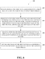
- FIG. 6 is a flowchart of an example process for encoding a video stream using slice-level reference picture reconstruction according to implementations of this disclosure.
- FIGS. 7A, 7B, 7C and 7D are examples of slice-level reference picture reconstruction according to implementations of this disclosure.
- FIG. 8 is another example of slice-level reference picture reconstruction according to implementations of this disclosure.
- Online multimedia data sharing such as a video conference call, a live-stream video broadcasting, or an Internet phone service, requires media data transmission with efficiency and fidelity.
- the media data can include audio data, video data, or any multimedia data including an audio sequence or a video sequence.
- media data can be stored in its original form or converted to form a video stream.
- the video stream can be encoded (or “compressed”) into a compressed video stream (e.g., a video bitstream) for transmission over a network.
- the compressed video stream can be transmitted over a network in data packets (or “packets” for simplicity).
- a picture of the video stream can be encoded using motion estimation (ME) and motion compensation (MC).
- a picture can be decoded using another picture as a reference (referred to as a “reference picture”).
- the reference picture can be an I-picture (a picture coded without referencing another picture), or a P-picture (a picture coded using another picture as a reference).
- the picture can be divided or segmented into one or more slices.
- ME and MC can be performed within each slice without relying on other slices in the same picture. As a result, when a slice is lost, other slices in the same picture are not affected.
- a slice can include one or more blocks.
- a decoder receives a slice from a picture, and sends a feedback message to an encoder indicating that the slice has been received.
- the encoder sets the slice as a reference slice, so that it can be used for encoding slices in subsequent pictures. It will take some time for the feedback message to arrive, especially when the network condition is jittery.
- the encoder Before receiving the feedback message, without knowing whether the slice has safely arrived at the decoder, the encoder will not use it as reference.
- the encoder can start using the slice as reference for encoding a new slice in a new picture and indicate this reference information in the slice header of the new slice.
- the decoder can tell from the slice header that the slice, which was received and acknowledged by the decoder in the feedback message, is going to be used as a reference slice for decoding the new slice.
- the slices to be predicted from the reference slices can be co-located slices, e.g., some areas of the slices from the same location in the picture that often do not incur much change from picture to picture.
- pictures including valid reference slices can be set as long-term reference pictures (LTRs). The LTRs will be updated when a new slice from a new picture is received.
- LTRs long-term reference pictures
- a slice can be included in one packet or divided into multiple packets.
- slice-level feedback messages to update reference slices used for encoding slices (such as co-located slices) of subsequent pictures, and without requiring that the whole picture to be received
- the slice-level reference picture reconstruction can increase packet loss resilience under jittery network conditions.
- the slice-level reference picture reconstruction techniques described in this disclosure can introduce a noticeable improvement in performance, bits savings, and mitigating effects on packet loss. For example, even when only one slice is received for a certain picture, that slice can still be used as a reference slice.
- the slice-level reference picture reconstruction techniques can be integrated or made compliant with existing video standards, such as, for example, H.264 and HEVC.
- FIG. 1 is a diagram of an example system 100 for media data transmission according to implementations of this disclosure.
- the media data can include audio data, video data, or any multimedia data including an audio sequence or a video sequence.
- the system 100 can include multiple apparatuses and networks, such as an apparatus 102 , an apparatus 104 , and a network 106 .
- the apparatuses can be implemented by any configuration of one or more computers, such as a microcomputer, a mainframe computer, a supercomputer, a general-purpose computer, a special-purpose/dedicated computer, an integrated computer, a database computer, a remote server computer, a personal computer, a laptop computer, a tablet computer, a cell phone, a personal data assistant (PDA), a wearable computing device, or a computing service provided by a computing service provider, for example, a web host or a cloud service provider.
- the computing device can be implemented in the form of multiple groups of computers that are at different geographic locations and can communicate with one another, such as by way of a network.
- system 100 can be implemented using general-purpose computers/processors with a computer program that, when executed, carries out any of the respective methods, algorithms, and/or instructions described herein.
- special-purpose computers/processors including specialized hardware can be utilized for carrying out any of the methods, algorithms, or instructions described herein.
- the apparatus 102 can have an internal configuration of hardware including a processor 108 and a memory 110 .
- the processor 108 can be any type of device or devices capable of manipulating or processing information.
- the processor 108 can include a central processor (e.g., a central processing unit or CPU).
- the processor 108 can include a graphics processor (e.g., a graphics processing unit or GPU).
- the processor 108 can include a special dedicated hardware accelerating processor.
- the processor 108 can be distributed across multiple machines or devices (each machine or device having one or more processors) that can be coupled directly or connected via a network (e.g., a local area network).
- the memory 110 can include any transitory or non-transitory device or devices capable of storing codes and data that can be accessed by the processor (e.g., via a bus).
- the memory 110 herein can be a random-access memory (RAM) device, a read-only memory (ROM) device, an optical/magnetic disc, a hard drive, a solid-state drive, a flash drive, a security digital (SD) card, a memory stick, a compact flash (CF) card, or any combination of any suitable type of storage device.
- RAM random-access memory
- ROM read-only memory
- SD security digital
- CF compact flash
- the memory 110 can be distributed across multiple machines or devices, such as in the case of a network-based memory or cloud-based memory.
- the memory 110 can include data, an operating system and applications.
- the data can include any data for processing (e.g., an audio stream, a video stream, or a multimedia stream).
- the applications can include programs that permit the processor 108 to implement instructions to generate control signals for performing functions of the methods in the following description.
- the apparatus 102 can also include a secondary (e.g., external) storage device (not shown).
- the secondary storage device can provide additional memory when high processing needs exist.
- the secondary storage device can be a storage device in the form of any suitable non-transitory computer-readable medium, such as a memory card, a hard disk drive, a solid-state drive, a flash drive, or an optical drive. Further, the secondary storage device can be a component of the apparatus 102 or can be a shared device accessible via a network.
- the application in the memory 110 can be stored in whole or in part in the secondary storage device and loaded into the memory 110 as needed for processing.
- the apparatus 102 can include input/output (I/O) devices.
- the apparatus 102 can include an I/O device 112 .
- the I/O device 112 can be implemented in various ways, for example, it can be a display that can be coupled to the apparatus 102 and configured to display a rendering of graphics data.
- the I/O device 112 can be any device capable of transmitting a visual, acoustic, or tactile signal to a user, such as a display, a touch-sensitive device (e.g., a touchscreen), a speaker, an earphone, a light-emitting diode (LED) indicator, or a vibration motor.
- a touch-sensitive device e.g., a touchscreen
- a speaker e.g., an earphone
- LED light-emitting diode
- the I/O device 112 can also be any type of input device either requiring or not requiring user intervention, such as a keyboard, a numerical keypad, a mouse, a trackball, a microphone, a touch-sensitive device (e.g., a touchscreen), a sensor, or a gesture-sensitive input device.
- a touch-sensitive device e.g., a touchscreen
- a sensor e.g., a gesture-sensitive input device.
- a gesture-sensitive input device e.g., a touchscreen
- the I/O device 112 is a display, for example, it can be a liquid crystal display (LCD), a cathode-ray tube (CRT), or any other output device capable of providing a visible output to an individual.
- an output device can also function as an input device—a touchscreen display configured to receive touch-based input, for example.
- the I/O device 112 can alternatively or additionally be formed of a communication device for transmitting signals and/or data.
- the I/O device 112 can include a wired means for transmitting signals or data from the apparatus 102 to another device.
- the I/O device 112 can include a wireless transmitter or receiver using a protocol compatible to transmit signals from the apparatus 102 to another device or to receive signals from another device to the apparatus 102 .
- the apparatus 102 can optionally include a communication device 114 to communicate with another device.
- the communication can be via a network 106 .
- the network 106 can be one or more communications networks of any suitable type in any combination, including, but not limited to, networks using Bluetooth communications, infrared communications, near field connections (NFCs), wireless networks, wired networks, local area networks (LANs), wide area networks (WANs), virtual private networks (VPNs), cellular data networks, or the Internet.
- the communication device 114 can be implemented in various ways, such as a transponder/transceiver device, a modem, a router, a gateway, a circuit, a chip, a wired network adapter, a wireless network adapter, a Bluetooth adapter, an infrared adapter, an NFC adapter, a cellular network chip, or any suitable type of device in any combination that is coupled to the apparatus 102 to provide functions of communication with the network 106 .
- the apparatus 104 includes a processor 116 , a memory 118 , an I/O device 120 , and a communication device 122 .
- the implementations of elements 116 - 122 of the apparatus 104 can be similar to the corresponding elements 108 - 114 of the apparatus 102 .
- the apparatus 102 can be used as a decoding apparatus (referred to as a “decoder”), and the apparatus 104 can be used as an encoding device (referred to as an “encoder”), or vice versa.
- the apparatus 102 can communicate with the apparatus 104 via the network 106 .
- the apparatuses 102 and 104 can also communicate with other apparatuses (not shown) connected to the network 106 .
- parts or components of the coding devices can include elements not limited to those shown in FIG. 1 , and can include more or fewer parts, components, and hardware or software modules for performing various functions in addition or related to encoding and decoding using slice-level reference picture reconstruction.
- the apparatuses 102 and 104 can be realized in hardware including, for example, intellectual property (IP) cores, application-specific integrated circuits (ASICs), programmable logic arrays, optical processors, programmable logic controllers, microcode, firmware, microcontrollers, servers, microprocessors, digital signal processors, or any other suitable circuit.
- IP intellectual property
- ASICs application-specific integrated circuits
- programmable logic arrays optical processors
- programmable logic controllers microcode, firmware, microcontrollers, servers, microprocessors, digital signal processors, or any other suitable circuit.
- processor should be understood as encompassing any the foregoing, either singly or in combination.
- the terms “signal,” “data,” and “information” are used interchangeably. Further, portions of the apparatuses 102 and 104 do not necessarily have to be implemented in the same manner.
- parts or components of the coding devices implementing the slice-level reference picture reconstruction can include elements not limited to those shown in FIG. 1 .
- the coding devices and systems can include more or fewer parts, components, and hardware or software modules for performing various functions in addition or related to encoding and decoding.
- FIG. 2 shows example pictures of a video stream 200 .
- the video stream 200 can include a series of pictures along the timeline, including pictures 202 - 208 .
- the picture 208 can be the current picture in the coding process.
- the reference pictures for the picture 208 as can be one or more of the pictures 206 , 204 , 202 , or another picture (not shown) coded before the picture 208 .
- Each picture of the video stream 200 can be divided into multiple processing units.
- the processing units are referred to as “macroblocks” or “coding tree blocks” (CTBs).
- CTBs coding tree blocks
- each processing unit can be further divided into one or more processing sub-units, in which the processing sub-units are referred to as “blocks” or “coding units” (CUs).
- the size and shape of the processing units and sub-units can be any size, such as 8 ⁇ 8, 8 ⁇ 16, 16 ⁇ 16, 32 ⁇ 32, 64 ⁇ 64, or any arbitrary shape. Typically, when a region has more details, the processing units and sub-units tend to be smaller in size.
- the processing units and sub-units are referred to as “blocks” hereinafter unless explicitly described otherwise.
- the picture 206 is shown to have 16 ⁇ 16 blocks, including a block 210 .
- the boundaries of the blocks are shown in dotted lines.
- the blocks can be grouped, forming a special region or partition of the picture.
- the picture can be divided into one or more regions or partitions, and each region or partition can include one or more blocks.
- Such regions or partitions can be referred to as “slices,” “tiles,” or another name specific to certain video coding standards.
- regions or partitions are referred to as “slices” hereinafter unless explicitly described otherwise herein.
- the picture 206 can be divided into four slices 212 - 218 , each slice having four blocks.
- the slices 212 - 218 can have boundaries 220 - 226 in between, shown as solid lines.
- Slices can be processed independently of other slices. For example, motion compensation and/or motion estimation can be performed for one slice (e.g., using blocks in the same slice).
- slices can be encoded simultaneously with and/or independently from the other slices.
- the slices 212 - 218 can be independently processed, which can increase the efficiency of video encoding.
- the slices can also be independently decoded at a decoder.
- Slices of an I-picture can be referred to as I-slices, and slices of a P-picture can be referred to as P-slices.
- ME and/or MC can be performed between two or more co-located slices in some implementations.
- co-located refers to two slices in two respective pictures having the same location in the picture.
- the location of a slice in a picture refers to the relative position of the slice within the picture.
- the location can be determined using a part of the slice as a reference point.
- the reference point can be within a block of the slice at the center, a corner, a boundary, or any position of the slice.
- two co-located slices can have the same size and the same shape. For example, for two slices in two pictures having the same size and shape, if the top left corners of the two slices have the same positions (e.g., coordinates) in the picture, the two slices are considered “co-located.” For example, the slice 228 of the picture 208 is co-located with the slice 212 of the picture 206 , and so on. If the slice 228 is a P-slice, it can use the co-located slice 212 as its reference slice. In some other implementations, for P-slices, ME and/or MC can be performed between two or more non-co-located slices. For example, if the slice 228 is a P-slice, it can use the non-co-located slice 214 , 216 , or 218 as its reference slice.
- a slice can include any number of any blocks in any configuration, and is not limited to the aforementioned examples (e.g., the slices 212 - 218 ).
- a slice can be in a rectangular shape, such as including blocks of adjacent rows.
- a slice can include blocks grouped in a non-contiguous manner, such as two or more non-contiguous block groups.
- a part of a first slice can be within a part of a second slice.
- the first slice can be enclosed by the second slice (e.g., the first slice can be within the second slice).
- the division or segmentation of the slices can be changed or unchanged in the video stream.
- the boundaries between the slices can be changed or unchanged.
- the pictures of the video stream can be divided into slices in the same pattern.
- the pattern of the slices can change from picture to picture in the video stream.
- FIG. 3 is a flowchart of an example process 300 of encoding a video stream 302 according to implementations of this disclosure.
- the video stream 302 can include an audio source stream, a video source stream, or any media stream including audio and/or video data.
- the process 300 can be implemented as software and/or hardware modules in the system 100 in FIG. 1 .
- the process 300 can be implemented as modules included in an encoder (e.g., the apparatus 104 in FIG. 1 ).
- the process 300 includes operations 304 - 308 to produce as output a compressed video stream 314 from a video stream 302 .
- the example encoding process 300 (either the whole process or some stages) can be further modified when implementing slice-level reference picture reconstruction described below in FIGS. 5 and 6 . In some instances, process 300 may not be necessary for the implementations of slice-level reference picture reconstruction.
- the video stream 302 is received by an encoder.
- the term “receive” used herein can refer to receiving, inputting, acquiring, retrieving, obtaining, reading, accessing, or any action in any manner for inputting information or data.
- the video stream 302 can be a video stream and include a series of video pictures (e.g., a current picture).
- an encoding process can include one or more of the following stages or operations: a prediction stage (e.g., for intra-prediction or inter-prediction), a transformation stage (with or without quantization), and an entropy encoding stage.
- the aforementioned stages can be used to output the compressed video stream 314 from the video stream 302 in a forward path of the encoding process as shown by the solid connection lines in FIG. 3 : an intra/inter prediction stage 304 , a transformation and/or quantization stage 306 , and an entropy encoding stage 308 .
- a current block of the current picture can be predicted using previously coded block(s) from the current picture.
- the current block of the current picture can be predicted using previously coded pictures as reference data.
- Previously coded pictures can include, for example, previously encoded and reconstructed pictures also referred to as reference pictures.
- motion estimation and compensation can be performed using the current picture and one or more reference pictures to generate motion data.
- a residual which is the difference between a predicted block and the current block, can be further transformed, quantized, and/or entropy encoded.
- a loop filter (not shown) can be additionally applied before the entropy encoding stage 308 .
- the loop filter can reduce distortion (e.g., blocking artifacts) introduced by the video compression.
- Other information used to decode the resulted video bitstream can also be entropy encoded, such as the prediction mode, transformation type, quantization level, and loop filter parameters (e.g., filter strength).
- the process 300 can further include a reconstruction path for reconstructing reference data to be used for predicting a future picture.
- the reconstruction path (shown by the dotted connection lines in FIG. 3 ) can include the following stages: a dequantization and/or inverse transformation stage 310 and a reconstruction stage 312 .
- the stages 310 and 312 can be used to ensure that both the encoder (e.g., the apparatus 104 in FIG. 1 ) and a decoder (e.g., the apparatus 102 in FIG. 1 ) can use the same reference data for prediction.
- a loop filter (not shown) can be additionally applied after the stage 312 .
- the reconstructed picture can be used without using the loop filter.
- the reconstruction can be similar to a reconstruction stage in a decoding process (e.g., stage 410 in FIG. 4 ).
- encoding process can be used to encode the video sequence.
- the encoding process can be performed in different orders, combined into fewer stages, and/or divided into more stages.
- quantization or transform can be optional in some implementations.
- a non-transform based encoder can quantize the residual data without transformation.
- FIG. 4 is a diagram of an example process 400 that can be used to decode a compressed video stream according to implementations of this disclosure.
- the process 400 can be implemented as software and/or hardware modules in the system 100 in FIG. 1 .
- some or all stages of the process 400 can be implemented as software or hardware modules included in the system 100 by a decoder (e.g., the apparatus 102 ).
- the decoder can be implemented by program codes stored in memory (e.g., the memory 110 ).
- the program codes can include computer-readable instructions that, when executed by a processor (e.g., the processor 108 ), cause the decoder to decode a compressed video stream in the manner described in FIG. 4 .
- the decoder can also be implemented as specialized hardware included in an apparatus (e.g., the apparatus 102 ).
- the decoder can be a hardware decoder.
- the process 400 includes operations 404 - 410 to reconstruct a video stream 412 from a compressed video stream 402 .
- the example process 400 (either the whole process or some stages) can be modified when implementing slice-level reference picture reconstruction of FIGS. 5-6 described below.
- the decoding process is similar to the reconstruction path of the video encoding process.
- the process 400 can include the following stages: an entropy decoding stage 404 , a dequantization and/or inverse transformation stage 406 , an intra/inter prediction stage 408 , and a reconstruction stage 410 .
- the reconstructed picture can be used as future reference data for processing a future picture successive to the current picture.
- the reconstructed picture can also be stored in a buffer (e.g., in the memory 110 in FIG. 1 ) to be used as the future reference data.
- the reconstructed picture can be filtered using a loop filter (not shown).
- Other structural variations of the process 400 can be used to decode the compressed video stream 402 .
- FIG. 5 is a flowchart of an example process 500 for encoding a video stream using slice-level reference picture reconstruction according to implementations of this disclosure.
- the process 500 can be implemented as software and/or hardware modules in the system 100 in FIG. 1 .
- the process 500 can be implemented as software modules stored in the memory 118 as instructions and/or data executable by the processor 116 of an encoder, such as the apparatus 104 in FIG. 1 .
- the process 500 can be implemented in hardware as a specialized chip storing instructions executable by the specialized chip. Some or all of the operations of the process 500 can be implemented at one or more stages of the process 300 in FIG. 3 .
- a first slice of a first picture of the video stream is encoded.
- the encoded slice is transmitted in the compressed video stream and received by a decoder, such as the apparatus 102 in FIG. 1 .
- the first slice can be associated with a slice number and will be referred to herein with the slice number (e.g., a slice “S 0 ”, shown in FIG. 7A as a slice 712 , herein referenced as slice “S 0 ” 712 ) along with the picture that the slice belongs to (e.g., a picture 702 ).
- the decoder Based on a determination that all data required for decoding the first slice of the first picture has been received, the decoder sends a feedback message indicative of having received the first slice of the first picture to the encoder, the process of which will be discussed in detail below in FIG. 6 .
- slice “S 0 ” 712 of a picture 702 is encoded and transmitted in the compressed video stream (“bitstream”).
- bitstream the compressed video stream
- a feedback message indicative of having received the first slice of the first picture is received from the decoder.
- the feedback message can be, for example, the feedback message indicative of having received slice “S 0 ” 712 of the picture 702 .
- the first slice of the first picture is set as a reference slice.
- the reference slice can be used for encoding a second picture of the video stream, which is encoded later in time than the first picture.
- the slice “S 0 ” of the picture 702 is set as a reference slice, which can be used for encoding subsequent pictures, such as a picture 704 in FIG. 7B .
- both the encoder and decoder can set a set of reference pictures used for predicting the second picture.
- the set of reference picture can be set to include each picture that is associated with at least one valid reference slice.
- the set of reference pictures used for predicting the second picture further includes a fourth picture encoded immediately prior to encoding the second picture (e.g., “last” picture).
- the fourth picture can be encoded and then decoded using the reconstruction path in FIG.
- the encoder and decoder can use the same reference picture reconstructed from the encoded video stream.
- the picture 704 can be set as a new reference picture, and the set of reference pictures after receiving the feedback message regarding slice “S 0 ” 718 of the picture 704 can include, for example, the picture 702 and the picture 704 , each including at least one valid reference slice.
- the first picture can be set as a new LTR picture.
- the picture 702 can be set as a new LTR picture for encoding subsequent pictures.
- the first slice of the first picture can be set as a valid reference slice.
- a corresponding slice of another picture, which was previously valid can be set as an invalid reference slice.
- a first slice of a third picture of the video stream in response to setting the first slice of the first picture as the reference slice for encoding the second picture of the video stream, can be as an invalid reference slice, wherein the first slice of the first picture and the first slice of the third picture are co-located, and the third picture was encoded prior to encoding the first picture.
- FIG. 7B as an example, when a slice “S 0 ” 718 of the picture 704 is set as a valid reference slice, the previously valid slice “S 0 ” 712 of the picture 702 is set as invalid.
- a first slice of the second picture of the video stream can be encoded with reference to the first slice of the first picture, wherein the first slice of the first picture and the first slice of the second picture are co-located.
- a slice header of the first slice of the second picture can include reference to the first slice of the first picture, which is used for predicting the first slice of the second picture during decoding.
- a slice “S 1 ” of the picture 704 can be encoded with reference to the slice “S 1 ” 714 of the picture 702 .
- the slice “S 1 ” of the picture 704 is co-located with the slice “S 1 ” 714 of the picture 702 .
- a second feedback message indicative of having received a second slice of the first picture is received from the decoder, wherein the second slice of the first picture is not the same as the first slice of the first picture. This occurs when multiple slices from the same picture are received by the decoder and multiple feedback messages are sent by the decoder.
- the encoder sets the second slice of the first picture as a reference slice for encoding the second picture of the video stream, and both the first slice and the second slice of the first picture are set as valid reference slices.
- the feedback message is indicative of having received the first slice and at least one other slice of the first picture. This occurs when multiple slices from the same picture are received by the decoder and one feedback message acknowledging all received slices are sent by the decoder. This will lower transmission and processing costs, but will increase the latency for updating the reference slices/pictures, as the decoder will have to wait longer for all the slices to arrive before sending the feedback message.
- FIG. 6 is a flowchart of an example process 600 of decoding a compressed video stream using slice-level reference picture reconstruction according to implementations of this disclosure.
- the compressed video stream can be received in the format of a video bitstream.
- the process 600 can be implemented as software and/or hardware modules in the system 100 in FIG. 1 .
- the process 600 can be implemented as modules included in a decoder (e.g., the apparatus 102 in FIG. 1 ).
- the operations of the process 600 can also be implemented as machine-readable instructions at, for example, at one or more stages of the process 400 in FIG. 4 .
- the process 600 includes operations 602 - 608 for slice-level reference picture reconstruction from the received video stream, which are set forth as follows.
- data associated with a first slice of a first picture of the encoded video stream is received from an encoder.
- data associated with the slice “S 0 ” 712 of a picture 702 is received from the encoder.
- a feedback message indicative of having received the first slice of the first picture is sent to the encoder.
- the decoder upon determining that all data required for decoding the slice “S 0 ” 712 has been received, the decoder sends a feedback message to the encoder indicative of having received slice “S 0 ” 712 of the picture 702 .
- the slice can arrive in one packet or multiple packets.
- the decoder decodes the first slice of the first picture based on the received data.
- the slice “S 0 ” 712 of the picture 702 can be decoded.
- a slice can be decoded using reference to other pictures, such as the set of reference pictures discussed above.
- the slice “S 0 ” 712 of the picture 702 can be decoded using previously decoded reference pictures.
- the reference pictures can also include the “last” picture in the sequence decoded immediately prior to decoding the first picture.
- a slice header of the first slice of the second picture can include reference to the first slice of the first picture, wherein the first slice of the first picture is used for predicting the first slice of the second picture during decoding.
- the decoded first slice of the first picture is set as a reference slice for decoding the first slice of the second picture of the encoded video stream.
- the first slice of the first picture and the first slice of the second picture can be co-located.
- slice “S 0 ” 718 of the picture 704 can be decoded using the co-located slice “S 0 ” 712 of the picture 702 , which is set as a reference slice in FIG. 7A .
- the first slice of the second picture of the video stream can be decoded with reference to the first slice of the first picture.
- the first slice of the second picture can be decoded using the first slice of the first picture as reference, based on information included in the slice header of the first slice of the second picture.
- the reference slices and pictures can be updated similar to the process 500 in FIG. 5 .
- the first picture can be set as a new LTR picture.
- the picture 702 can be set as a new LTR picture for decoding subsequent pictures, when the slice header indicates using the picture 702 as a reference picture.
- the first picture based on a determination that the first picture has not been set as a reference picture and in response to receiving, from the encoder, data associated with the first slice of the second picture with reference to the first slice of the first picture, the first picture can be set as a new reference picture for decoding the second picture.
- the first slice of the first picture can be set as a valid reference slice.
- a second feedback message indicative of having received the second slice of the first picture can be sent to the encoder, and the second slice of the first picture can be decoded, wherein the second slice of the first picture is not the same as the first slice of the first picture.
- Data associated with a second slice of the second picture of the encoded video stream with reference to the second slice of the first picture is received from the encoder.
- the second slice of the first picture is set as a reference slice for decoding the second picture, wherein both the first slice and the second slice of the first picture are set as valid reference slices.
- a first slice of a third picture of the video stream in response to setting the first slice of the first picture as the reference slice for decoding the second picture of the video stream, is set as an invalid reference slice.
- the first slice of the first picture and the first slice of the third picture are co-located, and the third picture is decoded prior to decoding the first picture.
- the feedback message is indicative of having received the first slice and at least one other slice of the first picture. In some other implementations, as soon as receiving a slice, a feedback message is sent.
- FIGS. 7A, 7B, 7C and 7D are examples of slice-level reference picture reconstruction according to implementations of this disclosure.
- each picture is divided into slices labeled as “S 0 ”, “S 1 ”, “S 2 ”.
- a slice labeled “S 0 ” corresponds to the first slice discussed above in the processes 500 and 600
- a slice labeled “S 1 ” corresponds to the second slice discussed above
- a slice labeled “S 2 ” corresponds to the third slice discussed above, and so on.
- Slices with the same labels are co-located. For example, slices labeled “S 0 ” are co-located. Similarly, slices labeled “S 2 ” are co-located. As previously discussed, the slice “S 0 ” 712 of picture 702 and the slice “S 0 ” 718 of picture 704 are co-located. Likewise, slice “S 2 ” 716 of the picture 702 and slice “S 2 ” 720 of the picture 706 are co-located.
- a picture (e.g., the picture 702 ) becomes decodable (e.g., partially or fully decodable).
- a feedback message (or multiple feedback messages) indicating that all the slices (in this example, slice “S 0 ” 712 , slice “S 1 ” 714 and slice “S 2 ” 716 ) are received is sent by the decoder back to the encoder over the network. There can be some transmitting delay.
- the picture (e.g., the picture 702 ) is marked as a long-term reference picture, e.g., LTR 0 .
- the slices (“S 0 ”, “S 1 ”, “S 2 ”) are made valid for ME and MC, and can be used as reference in subsequent coding process.
- the picture 702 becomes LTR 0 with all slices set as valid.
- a new slice “S 0 ” 718 of a newer picture, the picture 704 is received.
- a (second) feedback message indicating that the slice “S 0 ” 718 of the picture 704 has been received is sent back to the encoder.
- the newer picture e.g., the picture 704
- the picture 704 is marked as a long-term reference picture, e.g., LTR 1 , which can be used as reference in subsequent encoding process, together with the previous long-term reference pictures that are still valid.
- the picture 704 which includes the received slice “S 0 ” 718 , is set as LTR 1 .
- FIG. 7C another slice, e.g., slice “S 2 ” 720 of a newer picture 706 , is received.
- Another feedback message is sent back to the encoder.
- the encoder receives the feedback message, the corresponding picture, e.g., the picture 706 , is set as a valid long-term reference picture LTR 2 .
- the received slice “S 2 ” 720 is set a valid reference slice.
- only the slice “S 1 ” 714 of LTR 0 and the slice “S 0 ” 718 of LTR 1 remain valid (which means the slice “S 2 ” 716 of LTR 0 is set as invalid).
- the valid reference slices are the slice “S 1 ” 714 of the picture 702 , the slice “S 0 ” 718 of the picture 704 and the slice “S 2 ” 720 of the picture 706 .
- the process can proceed as shown in another example in FIG. 7D .
- FIG. 7D the first two pictures are received in the same way as the examples in FIGS. 7A-B .
- a feedback message indicating that both the slice “S 0 ” 722 and the slice “S 2 ” 720 are received is sent back to the encoder.
- the picture 706 can be set as a long-term reference picture, which can be used as a reference in subsequent encoding process, together with previous long-term reference pictures that are still valid.
- the picture 706 is set as LTR 2 with slices 722 , 720 ⁇ “S 0 ”, “S 2 ” ⁇ .
- the slice “S 1 ” 714 of the picture 702 is still valid, but the slice “S 0 ” of the picture 704 is set as invalid, because the newer “S 0 ”, the slice 722 , has become available in LTR 2 .
- future ME and MC of a slice is restricted to use references within the valid slices in LTR 0 , LTR 1 and LTR 2 (LTR 1 including no valid slice).
- a long-term reference picture with no valid reference slice can be replaced with a newer long-term reference picture, when the newer picture contains at least one valid reference slice.
- FIG. 8 is another example of slice-level reference picture reconstruction according to implementations of this disclosure. In this example, the process is shown in a timing point of view from left to right.
- the picture Pi and long-term reference pictures ⁇ LTRi ⁇ c 852 can be used as references.
- the corresponding long-term reference pictures at an encoder 800 are shown as ⁇ LTRi ⁇ c 802 .
- the first slice received after the picture Pi denoted as slice K
- the slice K is decoded by the current reference pictures, including the long-term reference pictures ⁇ LTRi ⁇ c 852 and optionally the “last” picture discussed above.
- a feedback message signaling “slice K is received” is sent to the encoder 800 . Depending on the network condition, it can take some time for the feedback message to arrive at the encoder 800 .
- the feedback message arrives the encoder 800 , for example, during encoding of a picture P(i+N), which occurs later in time than P(i+T).
- the long-term reference pictures can be updated to include the picture P(i+T).
- T 1.
- the updated long-term reference pictures ⁇ LTRi ⁇ n 804 can be used as references for encoding a future picture, such as picture P(i+N+1).
- the slice header can be fully or partially compliant with some video standards, such as, for example, H.264 and HEVC.
- the reference information can also be processed or encoded in other ways, and not necessarily be made to be compliant with any existing standards.
- the long-term reference pictures ⁇ LTRi ⁇ c 852 at the decoder 850 can be updated to include the picture P(i+1).
- the updated long-term reference pictures ⁇ LTRi ⁇ n 854 can be used as references to decode slices in pictures starting from P(i+N+1), e.g., picture P(i+5) in the illustrative example.
- any lost slices such as slices in the pictures P(i+2), P(i+3) or P(i+4), will not affect the decoding of the next picture P(i+5).
- the decoder will recover from packet loss of slices in P(i+2), P(i+3) or P(i+4).
- the decoder 850 can wait (subject to certain latency limit) until all slices have been received for a certain picture before sending the feedback message. This can mean more delay as the slices would not arrive at the same time. On the other hand, fewer feedback messages are sent (only one per picture), which lowers the transmission and processing cost.
- more than one decoder corresponds to one encoder, e.g., in a multicast scenario.
- the encoder can determine whether feedback messages have been received for a common slice from all of the decoders. If so, the LTRs can be updated.
- the information of the common slice can be carried in the slice header, such as one that is compliant with certain video standards. For example, when the packet loss rate is 10%, for a 1:4 multicast (one encoder, four decoders), the probability of a slice being received by all four decoders is 66%. When the packet loss rate drops to 20%, the probability drops to 41%. In another example, for a 1:16 multicast (one encoder, sixteen decoders), the probability of a slice being received by all sixteen decoders is 19% when the packet loss rate is 10%, and 2.8% when the packet loss rate is 20%.
- the processes described above can be carried out in the other decoders that are still running. Meanwhile, the broken decoders can be recovered when a new immediate direct fresh (IDR) picture is received.
- IDR immediate direct fresh
- the implementations of computing devices as described herein can be realized in hardware, software, or any combination thereof.
- the hardware can include, for example, computers, intellectual property (IP) cores, application-specific integrated circuits (ASICs), programmable logic arrays, optical processors, programmable logic controllers, microcode, microcontrollers, servers, microprocessors, digital signal processors or any other suitable circuit.
- IP intellectual property
- ASICs application-specific integrated circuits
- programmable logic arrays optical processors
- programmable logic controllers microcode, microcontrollers
- servers microprocessors, digital signal processors or any other suitable circuit.
- signal processors digital signal processors or any other suitable circuit.
- the aspects herein can be described in terms of functional block components and various processing operations.
- the disclosed processes and sequences may be performed alone or in any combination.
- Functional blocks can be realized by any number of hardware and/or software components that perform the specified functions.
- the described aspects can employ various integrated circuit components, e.g., memory elements, processing elements, logic elements, look-up tables, and the like, which can carry out a variety of functions under the control of one or more microprocessors or other control devices.
- the elements of the described aspects are implemented using software programming or software elements the disclosure can be implemented with any programming or scripting language such as C, C++, Java, assembler, or the like, with the various algorithms being implemented with any combination of data structures, objects, processes, routines or other programming elements.
- Implementations or portions of implementations of the above disclosure can take the form of a computer program product accessible from, for example, a computer-usable or computer-readable medium.
- a computer-usable or computer-readable medium can be any device that can, for example, tangibly contain, store, communicate, or transport a program or data structure for use by or in connection with any processor.
- the medium can be, for example, an electronic, magnetic, optical, electromagnetic, or a semiconductor device. Other suitable mediums are also available.
- Such computer-usable or computer-readable media can be referred to as non-transitory memory or media, and can include RAM or other volatile memory or storage devices that can change over time.
- a memory of an apparatus described herein, unless otherwise specified, does not have to be physically contained in the apparatus, but is one that can be accessed remotely by the apparatus, and does not have to be contiguous with other memory that might be physically contained in the apparatus.
- any of the individual or combined functions described herein as being performed as examples of the disclosure can be implemented using machine readable instructions in the form of code for operation of any or any combination of the aforementioned hardware.
- the computational codes can be implemented in the form of one or more modules by which individual or combined functions can be performed as a computational tool, the input and output data of each module being passed to/from one or more further module during operation of the methods and systems described herein.
- Information, data, and signals can be represented using a variety of different technologies and techniques.
- any data, instructions, commands, information, signals, bits, symbols, and chips referenced herein can be represented by voltages, currents, electromagnetic waves, magnetic fields or particles, optical fields or particles, other items, or a combination of the foregoing.
- example is used herein to mean serving as an example, instance, or illustration. Any aspect or design described herein as “example” is not necessarily to be construed as preferred or advantageous over other aspects or designs. Rather, use of the word “example” is intended to present concepts in a concrete fashion.
- the term “or” is intended to mean an inclusive “or” rather than an exclusive “or”. That is, unless specified otherwise, or clear from context, “X includes A or B” is intended to mean any of the natural inclusive permutations. In other words, if X includes A; X includes B; or X includes both A and B, then “X includes A or B” is satisfied under any of the foregoing instances.
Abstract
Description
Claims (15)
Priority Applications (3)
| Application Number | Priority Date | Filing Date | Title |
|---|---|---|---|
| US15/993,864 US10567756B2 (en) | 2018-05-31 | 2018-05-31 | Slice level reference picture reconstruction |
| CN201810985675.4A CN110557635B (en) | 2018-05-31 | 2018-08-28 | Video stream encoding method and apparatus for decoding encoded video stream |
| EP19160634.2A EP3576411A1 (en) | 2018-05-31 | 2019-03-04 | Slice-level reference picture reconstruction |
Applications Claiming Priority (1)
| Application Number | Priority Date | Filing Date | Title |
|---|---|---|---|
| US15/993,864 US10567756B2 (en) | 2018-05-31 | 2018-05-31 | Slice level reference picture reconstruction |
Publications (2)
| Publication Number | Publication Date |
|---|---|
| US20190373253A1 US20190373253A1 (en) | 2019-12-05 |
| US10567756B2 true US10567756B2 (en) | 2020-02-18 |
Family
ID=65686754
Family Applications (1)
| Application Number | Title | Priority Date | Filing Date |
|---|---|---|---|
| US15/993,864 Active 2038-07-31 US10567756B2 (en) | 2018-05-31 | 2018-05-31 | Slice level reference picture reconstruction |
Country Status (3)
| Country | Link |
|---|---|
| US (1) | US10567756B2 (en) |
| EP (1) | EP3576411A1 (en) |
| CN (1) | CN110557635B (en) |
Families Citing this family (1)
| Publication number | Priority date | Publication date | Assignee | Title |
|---|---|---|---|---|
| WO2022205064A1 (en) * | 2021-03-31 | 2022-10-06 | 华为技术有限公司 | Video encoder, video decoder and corresponding method |
Citations (3)
| Publication number | Priority date | Publication date | Assignee | Title |
|---|---|---|---|---|
| EP0763944A2 (en) | 1995-09-18 | 1997-03-19 | Oki Electric Industry Company, Limited | Video coder, decoder and transmission system |
| US20080247463A1 (en) | 2007-04-09 | 2008-10-09 | Buttimer Maurice J | Long term reference frame management with error feedback for compressed video communication |
| US20130058405A1 (en) * | 2011-09-02 | 2013-03-07 | David Zhao | Video Coding |
Family Cites Families (2)
| Publication number | Priority date | Publication date | Assignee | Title |
|---|---|---|---|---|
| KR100374245B1 (en) * | 1996-04-19 | 2003-05-09 | 오끼 덴끼 고오교 가부시끼가이샤 | Image Encoder, Image Decoder and Image Transfer System |
| US20160165227A1 (en) * | 2014-12-04 | 2016-06-09 | Arris Enterprises, Inc. | Detection of audio to video synchronization errors |
-
2018
- 2018-05-31 US US15/993,864 patent/US10567756B2/en active Active
- 2018-08-28 CN CN201810985675.4A patent/CN110557635B/en active Active
-
2019
- 2019-03-04 EP EP19160634.2A patent/EP3576411A1/en active Pending
Patent Citations (3)
| Publication number | Priority date | Publication date | Assignee | Title |
|---|---|---|---|---|
| EP0763944A2 (en) | 1995-09-18 | 1997-03-19 | Oki Electric Industry Company, Limited | Video coder, decoder and transmission system |
| US20080247463A1 (en) | 2007-04-09 | 2008-10-09 | Buttimer Maurice J | Long term reference frame management with error feedback for compressed video communication |
| US20130058405A1 (en) * | 2011-09-02 | 2013-03-07 | David Zhao | Video Coding |
Non-Patent Citations (6)
| Title |
|---|
| Athanasios Leontaris et al: "Multiple Reference Motion Compensation: A Tutorial Introduction and Survey", Foundations and Trends in Signal Processing, Now Publishers, Hanover, Mass., USA. vol. 2, No. 1, Jan. 1, 2008 (Jan. 1, 2008), pp. 247-364, XP007917565, ISSN: 1932-8354, DOI: 10.1561/2000000019. |
| ATHANASIOS LEONTARIS, PAMELA C. COSMAN, ALEXIS M. TOURAPIS: "Multiple Reference Motion Compensation: A Tutorial Introduction and Survey", FOUNDATIONS AND TRENDS® IN SIGNAL PROCESSING, NOW PUBLISHERS, HANOVER, MASS., USA, vol. 2, no. 4, 1 January 2008 (2008-01-01), Hanover, Mass., USA, pages 247 - 364, XP007917565, ISSN: 1932-8354, DOI: 10.1561/2000000019 |
| Extended European search report issued in corresponding European application No. 19160634.2 dated Sep. 17, 2019. |
| Fukunaga S et al: "Error resilient video coding controlled by backward channel signaling", Signal Processing. Image Communication, Elsevier Science Publishers, Amsterdam, NL, vol. 14, No. 6-8, May 1, 1999 (May 1, 1999), pp. 531-540, XP004165393, ISSN: 0923-5965, DOI: 10.1016/S0923-5965 (99) 00005-3. |
| FUKUNAGA, S. MATSUMURA, Y. NAKAI, T.: "Error resilient video coding controlled by backward channel signaling", SIGNAL PROCESSING. IMAGE COMMUNICATION., ELSEVIER SCIENCE PUBLISHERS, AMSTERDAM., NL, vol. 14, no. 6-8, 1 May 1999 (1999-05-01), NL, pages 531 - 540, XP004165393, ISSN: 0923-5965, DOI: 10.1016/S0923-5965(99)00005-3 |
| Oki Electronic et al: "Proposed Amendments to Annex N of H.263+", 1. VCEG Meeting; Jun. 24, 1997-Jun. 27, 1997; Portland, OR, US; (Videocoding Experts Group of ITU-T SG.16), No. q15a28, Jun. 20, 1997 (Jun. 20, 1997), XP030002607. |
Also Published As
| Publication number | Publication date |
|---|---|
| CN110557635A (en) | 2019-12-10 |
| CN110557635B (en) | 2022-04-05 |
| EP3576411A1 (en) | 2019-12-04 |
| US20190373253A1 (en) | 2019-12-05 |
Similar Documents
| Publication | Publication Date | Title |
|---|---|---|
| CN113261298B (en) | Video encoding and decoding method and device | |
| CN113196756B (en) | Video encoding and decoding method and device | |
| JP5847970B2 (en) | Frame segmentation in video coding | |
| US10390049B2 (en) | Electronic devices for sending a message and buffering a bitstream | |
| CN112806008B (en) | Video decoding method, video decoding device, computer equipment and storage medium | |
| JP2014510440A (en) | Subslice in video coding | |
| US10567757B2 (en) | Dynamic reference picture reconstruction | |
| US9491487B2 (en) | Error resilient management of picture order count in predictive coding systems | |
| US20220353513A1 (en) | Encoding and decoding using tiling | |
| CN111277841B (en) | Method and apparatus for performing error concealment in video communication | |
| US20160241863A1 (en) | Syntax parsing apparatus with multiple syntax parsing circuits for processing multiple image regions within same frame or processing multiple frames and related syntax parsing method | |
| US10567756B2 (en) | Slice level reference picture reconstruction | |
| US10630747B2 (en) | Integer multiple description coding system | |
| KR20200140857A (en) | Techniques for Multiple Conformance Points in Media Coding | |
| US10567781B2 (en) | Progressive I-slice reference for packet loss resilient video coding | |
| US20140341288A1 (en) | Video encoding method and apparatus for determining size of parallel motion estimation region based on encoding related information and related video decoding method and apparatus | |
| CN106131565B (en) | Video decoding and rendering using joint jitter-frame buffer | |
| CN113491128B (en) | Method and related apparatus for decoded picture memory management | |
| RU2780809C1 (en) | Signalling of the image header parameters | |
| JP2022538551A (en) | video coding layer up switching instruction | |
| CN113302931A (en) | Identifying tiles from network abstraction unit headers |
Legal Events
| Date | Code | Title | Description |
|---|---|---|---|
| FEPP | Fee payment procedure |
Free format text: ENTITY STATUS SET TO UNDISCOUNTED (ORIGINAL EVENT CODE: BIG.); ENTITY STATUS OF PATENT OWNER: LARGE ENTITY Free format text: ENTITY STATUS SET TO UNDISCOUNTED (ORIGINAL EVENT CODE: BIG.); ENTITY STATUS OF PATENT OWNER: SMALL ENTITY |
|
| FEPP | Fee payment procedure |
Free format text: ENTITY STATUS SET TO SMALL (ORIGINAL EVENT CODE: SMAL); ENTITY STATUS OF PATENT OWNER: LARGE ENTITY Free format text: ENTITY STATUS SET TO SMALL (ORIGINAL EVENT CODE: SMAL); ENTITY STATUS OF PATENT OWNER: SMALL ENTITY |
|
| AS | Assignment |
Owner name: AGORA LAB, INC., CALIFORNIA Free format text: ASSIGNMENT OF ASSIGNORS INTEREST;ASSIGNORS:ZHONG, SHENG;DAI, WEI;ZHUANG, ZESEN;REEL/FRAME:046414/0812 Effective date: 20180521 |
|
| STPP | Information on status: patent application and granting procedure in general |
Free format text: NOTICE OF ALLOWANCE MAILED -- APPLICATION RECEIVED IN OFFICE OF PUBLICATIONS |
|
| STPP | Information on status: patent application and granting procedure in general |
Free format text: PUBLICATIONS -- ISSUE FEE PAYMENT RECEIVED |
|
| STCF | Information on status: patent grant |
Free format text: PATENTED CASE |
|
| FEPP | Fee payment procedure |
Free format text: ENTITY STATUS SET TO UNDISCOUNTED (ORIGINAL EVENT CODE: BIG.); ENTITY STATUS OF PATENT OWNER: LARGE ENTITY |
|
| MAFP | Maintenance fee payment |
Free format text: PAYMENT OF MAINTENANCE FEE, 4TH YEAR, LARGE ENTITY (ORIGINAL EVENT CODE: M1551); ENTITY STATUS OF PATENT OWNER: LARGE ENTITY Year of fee payment: 4 |