EP2737094B1 - Method and regulator for adjusting the burn-through point in a sintering machine - Google Patents
Method and regulator for adjusting the burn-through point in a sintering machine Download PDFInfo
- Publication number
- EP2737094B1 EP2737094B1 EP12746044.2A EP12746044A EP2737094B1 EP 2737094 B1 EP2737094 B1 EP 2737094B1 EP 12746044 A EP12746044 A EP 12746044A EP 2737094 B1 EP2737094 B1 EP 2737094B1
- Authority
- EP
- European Patent Office
- Prior art keywords
- temperature
- point
- burn
- conveying speed
- conveying
- Prior art date
- Legal status (The legal status is an assumption and is not a legal conclusion. Google has not performed a legal analysis and makes no representation as to the accuracy of the status listed.)
- Active
Links
- 238000005245 sintering Methods 0.000 title claims description 83
- 238000000034 method Methods 0.000 title claims description 50
- 238000005259 measurement Methods 0.000 claims description 124
- 239000000463 material Substances 0.000 claims description 54
- 230000033228 biological regulation Effects 0.000 claims description 25
- 230000006978 adaptation Effects 0.000 claims description 10
- 230000001174 ascending effect Effects 0.000 claims description 4
- 239000002912 waste gas Substances 0.000 description 14
- 230000001105 regulatory effect Effects 0.000 description 9
- 238000009826 distribution Methods 0.000 description 7
- 238000009529 body temperature measurement Methods 0.000 description 5
- 238000011156 evaluation Methods 0.000 description 5
- 238000012937 correction Methods 0.000 description 4
- 238000010276 construction Methods 0.000 description 3
- 238000010438 heat treatment Methods 0.000 description 3
- 239000002801 charged material Substances 0.000 description 2
- 230000003247 decreasing effect Effects 0.000 description 2
- 238000011161 development Methods 0.000 description 2
- 230000000630 rising effect Effects 0.000 description 2
- 239000000126 substance Substances 0.000 description 2
- 239000002699 waste material Substances 0.000 description 2
- 238000001816 cooling Methods 0.000 description 1
- 230000007423 decrease Effects 0.000 description 1
- 238000010586 diagram Methods 0.000 description 1
- 230000000694 effects Effects 0.000 description 1
- 238000004519 manufacturing process Methods 0.000 description 1
- 238000005457 optimization Methods 0.000 description 1
- 238000012545 processing Methods 0.000 description 1
- 238000000926 separation method Methods 0.000 description 1
- 230000009469 supplementation Effects 0.000 description 1
- 230000009897 systematic effect Effects 0.000 description 1
- 238000012360 testing method Methods 0.000 description 1
Images

Classifications
-
- C—CHEMISTRY; METALLURGY
- C22—METALLURGY; FERROUS OR NON-FERROUS ALLOYS; TREATMENT OF ALLOYS OR NON-FERROUS METALS
- C22B—PRODUCTION AND REFINING OF METALS; PRETREATMENT OF RAW MATERIALS
- C22B1/00—Preliminary treatment of ores or scrap
- C22B1/14—Agglomerating; Briquetting; Binding; Granulating
- C22B1/16—Sintering; Agglomerating
- C22B1/20—Sintering; Agglomerating in sintering machines with movable grates
- C22B1/205—Sintering; Agglomerating in sintering machines with movable grates regulation of the sintering process
-
- F—MECHANICAL ENGINEERING; LIGHTING; HEATING; WEAPONS; BLASTING
- F27—FURNACES; KILNS; OVENS; RETORTS
- F27B—FURNACES, KILNS, OVENS OR RETORTS IN GENERAL; OPEN SINTERING OR LIKE APPARATUS
- F27B21/00—Open or uncovered sintering apparatus; Other heat-treatment apparatus of like construction
- F27B21/06—Endless-strand sintering machines
-
- F—MECHANICAL ENGINEERING; LIGHTING; HEATING; WEAPONS; BLASTING
- F27—FURNACES; KILNS; OVENS; RETORTS
- F27D—DETAILS OR ACCESSORIES OF FURNACES, KILNS, OVENS OR RETORTS, IN SO FAR AS THEY ARE OF KINDS OCCURRING IN MORE THAN ONE KIND OF FURNACE
- F27D19/00—Arrangements of controlling devices
- F27D2019/0006—Monitoring the characteristics (composition, quantities, temperature, pressure) of at least one of the gases of the kiln atmosphere and using it as a controlling value
Definitions
- This invention relates to a method and a regulator for adjusting the burn-through point in a sintering machine.
- the material to be sintered which for example contains ores
- a conveying path for example a traveling grate or grate carriage
- ignited and past windboxes arranged in conveying direction and operated in suction direction transported up to a material dump.
- the material to be sintered is burnt to form a sinter cake and at the end of the sintering machine discharged near the material dump, for example by raking off, and supplied to succeeding processes.
- the temperature determined by the temperature of the material to be sintered is measured at at least three measurement points arranged one after the other along the conveying path, and the conveying speed of the sintering machine is adjusted in dependence on the position of a maximum measured temperature relative to the position of a previously selected burn-through point on the conveying path.
- Heating is effected by igniting the material surface on the sintering machine subsequent to the material intake.
- the ignited material subsequently is conveyed on the sintering machine, wherein the material ignited on its surface burns through over the entire height of the material to be sintered.
- the temperature measured in the vicinity of the windbox is at a maximum.
- the sintered material already cools down during the further conveyance on the sintering machine.
- burn-through point regulations take into account the temperatures at the windboxes in particular in the last quarter of sintering machines, in order to determine the burn-through point.
- the maximum temperature value is determined from the measured temperatures and the burn-through point is determined therefrom. By means of a comparison, it is determined in which one of the windboxes the maximum temperature value exists. This position is compared with the preselected position for the desired burn-through point.
- the conveying speed of the sintering machine is increased by a firmly defined factor. If the windbox with the maximum measured temperature value is located after the selected position for the burn-through point, the machine speed is reduced by the same, firmly defined factor.
- a method and an apparatus for regulating the conveying speed of a sintering machine are known.
- the temperature and the pressure of the waste air are measured in one of the plurality of consecutively arranged windboxes of a Dwight-Lloyd sintering machine and it is checked whether these measured values lie within a desired range. This indicates that the sintering process will be completed within the desired time frame or at the desired position of the sintering machine.
- the temperature profile of the temperatures measured in consecutively arranged windboxes shows a maximum in the burn-through point of the sinter bed.
- the measured pressure in the waste gases sucked in through the sinter bed remains approximately constant until reaching the burn-through point and drops distinctly after reaching the burn-through point.
- This regulation however is comparatively expensive, because two different measured values must be considered, in order to be able to reliably determine the burn-through point.
- fluctuations of the absolute values of the measured pressure can occur for example in dependence on the load of the sintering machine on the grate carriage. Therefore, this measured value is suitable for a regulation of the transport speed of the sintering machine only to a limited extent.
- US 4,065,295 describes a method for regulating the conveying speed on the basis of a measurement of the temperature measured in collectors of the windboxes.
- a regulating variable of the regulation is the temperature of all waste gases from all windboxes arranged one after the other on the sintering machine, which is measured in a collecting line shortly before the suction blower.
- the deviation of the mean temperature of all waste gases is used, which leave the windboxes with a temperature of more than 100 °C. This variable reacts faster than the total temperature of the collected waste gases in the collecting line.
- This method also can be employed when no temperature maximum or only a temperature maximum locally adulterated by external influences can be detected in the windboxes.
- the determination of the maximum temperature in the consecutively arranged windboxes is proposed as second regulating variable in a cascaded regulation, which corresponds to the current burn-through point.
- the desired burn-through point is determined on the basis of the temperature of the waste gases in the collecting line. In this way, inaccuracies in the determination of the maximum temperature should be compensated, for example in the last windbox.
- This regulation also is expensive, since two regulating variables must be determined.
- the regulation for adjusting a burn-through point only can be employed when a maximum also is found in the temperature distribution. For example, this is not the case when the material to be sintered is not yet sintered through up to the material dump.
- US 3,399,053 describes a method and an apparatus for regulating the conveying speed of a sintering machine, in which in three windboxes each arranged at the end of the conveying path and in the middle of the conveying path of the sintering machine the temperatures are measured, in order to continuously regulate the conveying speed and adjust the desired burn-through point. From the three temperature measurements at the end of the conveying path, the current maximum of the temperature distribution along the conveying path is determined by adaptation of a parabola. This current maximum is compared with the desired position of the maximum and the burn-through point, respectively, wherein a change of the conveying speed of the sintering machine is derived from a deviation.
- the conveying speed of the sintering machine then is adapted in dependence on the current maximum of the temperature and the predicted change rate.
- the predicted change rate By taking into account the predicted change rate, changes of the sinter characteristics for example of subsequently introduced material can quickly be taken into account.
- this method is subject to a great uncertainty, because the individual temperature measurements each include comparatively great errors, which beside possible systematic influences also are accidentally influenced by the not exactly predictable composition of the sinter cake.
- An adaptation of a parabola on the basis of such faulty variables can lead to the fact that the adaptation itself also is faulty and the maximum of the temperature distribution is determined with a considerable distance to the actual maximum. The same applies to the prediction of the change rate, so that on the whole an unstable regulation is obtained.
- this object is solved with a method according to claim 1 and with a regulator according to claim 8.
- the profile of the temperature of three, in particular exactly three, consecutively arranged measurement points is compared.
- These measurement points possibly can be arranged directly one after the other and/or one after the other separated by other measurement points.
- a maximum of the temperature is assumed when the first and third measurement points in conveying direction have a lower temperature value than the second measurement point.
- the invention particularly advantageously is carried out with the evaluation of exactly three measurement points, it is also possible to evaluate more than three measurement points, wherein in this case for example the first and the last measurement point must have a lower temperature value than some or all middle measurement points located in between, in order to be able to determine a maximum.
- the change point in a sequence of measurement points is sought particularly advantageously in accordance with the invention, in which a sequence of rising temperature values changes into a sequence of falling temperature values. This change point then is assumed as the maximum of the temperature curve.
- the regulation according to the invention proposes to reduce the conveying speed of the sintering machine when there is a sequence of rising temperature values up to the last measurement point, in order to bring the maximum of the temperature of the material to be sintered into the region of the conveying path.
- the conveying speed can also be increased by a specified value when the first, second and third measurement points form a descending series of temperature values. This indicates that the material to be sintered already has reached its burn-through point before reaching the first measurement point. Thus, no maximum is assumed in this case either.
- a sequence of three measured values is sought in accordance with the invention, which reveal the above-described criterion for recognizing a maximum in the temperature profile. If such maximum has been recognized, the search for the maximum can be stopped in accordance with the invention. Alternatively, however, it is also possible to continue the search and thus carry out a consistency check of the measured values, in order to find out for example whether two maxima are recognized. If this would be the case, an error message of the regulation might be issued, so that the sintering process is checked for example by other parameters.
- the search for maxima is continued in three consecutively arranged measurement points, in that from all measurement points to be evaluated sequences of three measurement points to be evaluated one after the other each are formed and checked, wherein instead of the exactly three measurement points to be evaluated one after the other, more measurement points, e.g. four or five, can be evaluated, as described already.
- the search for the maximum is not limited to three measurement points, but there are always compared three successive measurements.
- the measurement points can be measurement points arranged directly one after the other along the conveying path.
- the measurement points to be evaluated are defined by fixed checking sequences of measurement points. It is also possible that measurement points not to be evaluated are located between consecutively arranged measurement points to be evaluated in conveying direction.
- an essential advantage of the proposed method also consists in that the temperature profile along the conveying path is evaluated as the only regulating variable in accordance with the invention. This allows to provide a single sensor, namely a temperature sensor, per measurement point. This is particularly advantageous, because the sensors used in technical plants such as a sintering plant must be robust, as otherwise they can quickly be damaged. Providing a plurality of different sensors per measurement point therefore considerably increases the costs of the regulation according to the invention.
- the desired and selected burn-through point preferably lies shortly before the end of the conveying path on the sintering machine, the measurement points preferably also are arranged at the end of the conveying path before the material dump, for example in the last quarter of the sintering machine.
- more than three measurement points also are provided in accordance with the invention, in order to be able to determine the maximum of a temperature distribution over a major part of the conveying path.
- a number of four to six measurement points is particularly preferred in accordance with the invention, which in general covers a sufficient length of the conveying path on the sintering machine.
- the sintering machine is divided into uniform sections. In terms of construction, a segment width of 3 m was found to be advantageous. Each of these segments has a wind box, wherein the last four wind boxes are halved, to provide for a more exact definition of the burn-through point.
- the measurement points can be arranged in the wind boxes, preferably in wind boxes arranged directly one after the other.
- the maximum local resolution of the temperature distribution then corresponds to the diameter or the extension of a wind box in conveying direction, when in each windbox of the sintering machine or at least in each windbox of the sintering machine from the region of interest a measurement point is arranged.
- the measurement points preferably are located in the vicinity of the suction openings of the windboxes, in which the waste gases sucked in by the suction blower behind the windboxes through the material to be sintered are collected.
- the temperature of the waste gases is directly and decisively determined by the temperature of the material to be sintered, wherein the temperature profile of these waste gases in particular follows the temperatures in the material to be sintered along the conveying path.
- three measurement points can also be selected from a plurality of consecutively arranged measurement points, wherein the first, second and third measurement points are arranged one after the other in conveying direction, but measurement points not considered are arranged between the measurement points. In this way, a different width of the measurement curve can also be taken into account.
- a windbox is divided into several, i.e. two or more, segments in conveying direction and in each segment a measurement point is arranged.
- the measurement can be carried out with a generally better resolution, since the conveying path can be scanned with the resolution of the resolution provided in the windboxes.
- the segments can be logically organized, in that the different temperature sensors are arranged in the different regions of the windbox. Possibly, a constructional separation of the segments can also be effected, for example by suitable baffle plates in the suction openings or funnels.
- the height of the adaptation when changing the conveying speed in the case of an assumed maximum of the temperature can depend on the value of the deviation between the position of the assumed maximum of the temperature and the position of the selected burn-through point. Depending on the deviation of the actual from the desired burn-through point, an adjustment in direction of the desired or selected burn-through point thereby is accelerated.
- the adjustment of the height of the adaptation for example can be effected via the regulation parameters of the used regulator, a P-, PI-, PID- or other regulator.
- a value table can also be specified for various value ranges of the deviation, from which the height of the adaptation of the change of the conveying speed will then be read.
- the height of the adaptation can be fixed, i.e. a change of the conveying speed can be effected by a fixed value.
- the objective of this change is to shift the burn-through point onto the sintering machine or into the region of the measurement points on the sintering machine, so that then a maximum is found.
- the above-described process of shifting the actual burn-through point onto the selected burn-through point can be effected.
- an optimized conveying speed can be determined from a plant-specific burn-through rate, the composition of the material to be sintered, the material charging height and the length of the sintering machine, preferably the length of the sintering machine between the ignition point of the material to be sintered and the selected burn-through point.
- This theoretically determined, optimized conveying speed can be compared with the current conveying speed and/or be taken into account when changing the conveying speed.
- the comparison of the optimized conveying speed and the current conveying speed can be employed for finding the conveying speed suitable for the process more quickly, so as to quickly find the conveying speed to be adjusted.
- the proposed comparison can additionally or alternatively be employed for a plant-specific optimization of the burn-through rate, when a maximum of the temperature is found.
- the burn-through rate mostly results from theoretical considerations concerning the plant, which in the current operation can be specified by measured values.
- the burn-through rate can be used for specifying an approximate conveying speed as starting value of the regulation, in order to minimize possible regulation deviations and generate a small signal behavior of the regulation, which provides for a particularly fast correction.
- warning message there can also be formed a difference between the current, actual conveying speed and the optimum conveying speed, with a warning message being issued upon exceeding a threshold value.
- the warning message possibly can also contain a reference to a conveying speed to be adjusted favorably, in particular when no maximum can be assumed or found on checking the measurement points.
- the present invention also relates to a regulator for adjusting the burn-through point in a sintering machine.
- This regulator includes a calculating unit and at least three ports for connecting temperature sensors associated to individual measurement points and an output for specifying a conveying speed.
- a calculating unit for connecting temperature sensors associated to individual measurement points and an output for specifying a conveying speed.
- more temperature sensors can be connected to the regulator, with the number of the measurement points optimally corresponding to the number of the ports.
- the calculating unit is adapted to carry out the above-described method or parts thereof, for example by means of a suitable software.
- a development of the regulator according to the invention provides that the regulator is integrated into a control means of the sintering machine, which specifies the conveying speed of the conveying path of the sintering machine.
- the control can actuate suitable drive units of the conveying path, in particular of a possibly circulating conveyor belt or a trolley.
- the drive units in particular can be driven by an electric motor or hydraulically.
- the output of the regulator for specifying the conveying speed is connected to a control input of the controller. This port can also have been realized in an integrated calculating unit without recognizable outputs and control inputs, when the regulation and the control are implemented in a common microprocessor.
- the regulator temperature sensors can be connected, which in conveying direction are arranged on wind boxes consecutively arranged along the conveying path of the sintering machine, preferably in wind boxes driven in suction direction, and each form a measurement point.
- a reliable temperature measurement in particular can be effected when the temperature sensors are arranged in the suction means of the windboxes, for example in tapering slots or funnel-shaped openings.
- waste gases sucked through the material to be sintered are sucked in from an exactly defined region in which a certain burn-through degree of the material to be sintered has been reached.
- At least one suction means can be formed segmented in conveying direction, wherein in several or all segments of the suction means a temperature sensor each is arranged as measurement point.
- Fig. 1 schematically shows a sintering machine 1 on which granular or powdery substances, for example ores, are connected with each other by heating.
- a material dump 2 the material to be heated therefore is charged onto a conveying path 3 formed for example as circulating grate.
- the conveying path 3 moves in the conveying direction designated by the arrow F.
- the material to be sintered first is passed through below an igniter 4 which ignites the material to be sintered on its surface.
- the superficially ignited material to be sintered burns through in its bed height, before it is discharged as sinter from the conveying path 3 through the material dump 5, in order to be supplied for example to a succeeding process.
- the sintering process is completed.
- the desired burn-through point D is selected in the process. Usually, the selected burn-through point D lies shortly before the end of the conveying path 3 and the material dump 5 in conveying direction F.
- windboxes 6 are provided below the conveying path 3, which via a suction line 7 are connected to a blower 8 operated in suction direction.
- the windboxes 6 include suction means 9 formed as longitudinal slots, which have their largest opening on the side facing the conveying path 3, in order to suck in the waste gases generated during burn-through of the material to be sintered as a result of the negative pressure generated by the blower 8.
- the windboxes 6 each are arranged below the conveying path 3 with their suction means 9 adjacent to each other, wherein for clarity not all windboxes 6 are shown in Fig. 1 .
- not all of the illustrated wind boxes with their suction means 9 are provided with reference numerals for better clarity.
- measurement points 10 each are arranged, not all of which are provided with reference numerals for the sake of clarity.
- the measurement points 10 each include a temperature sensor arranged in the suction means 9 of a windbox 6, which sensor measures the temperature of the waste gases sucked in from the material to be sintered on the conveying bed in the region arranged above the suction means 9.
- the measurement points M1 to M5 are connected to a regulator 12 in which the method described below takes place.
- a controller 13 is provided, which includes an output 14 for specifying a conveying speed.
- This output 14 is connected with a drive unit 15 of the conveying path 3, in order to move the conveying path 3 in conveying direction with the conveying speed specified by the controller 13.
- the regulator 12 and the controller 13 each include calculating units, possibly also a common calculating unit, which are adapted to carry out the method described below and to actuate the conveying path 3.
- the method proposed according to the invention for adjusting the burn-through point D of the sintering machine 1 provides that the temperatures of the waste gases each are measured at the measurement points M1 to M5.
- a typical temperature profile of these waste gases in a sintering machine provides that in measurement points 10 succeeding each other in conveying direction the temperature values rise, until the burn-through point D is reached. After reaching the burn-through point D, the sintered material cools down again, so that the temperature of the waste gases decreases. The temperature maximum thus is reached in the burn-through point D.
- the temperature profile measured in the measurement points M1 to M5 now is analyzed, as will be explained below with reference to Fig. 2 .
- the measured temperature values of the measurement points M(i-1), M(i) and M(i+1) each are compared with each other.
- the position of the measurement point M(i) is defined as current burn-through point D(i) and the difference to the selected burn-through point D is formed.
- the conveying speed in the regulator 12 or controller 13 is adapted, wherein the adaptation for example is effected on the basis of a suitable parameterization of the regulation parameters.
- the procedure goes on to the next measurement point M(i+1) and the test is repeated, until the last measurement point is reached. If also for the last measurement point the value M(i) is smaller than the measured value M(i-1), the conveying speed is increased by a constant K1, because the sequence of measured values indicates that the burn-through point lies on the conveying path 3 before the first measurement point M1.
- the procedure also goes on to the next measurement point, until all measurement points are processed. If this condition also is satisfied in the last measurement point, an ascending series of measured temperature values exists, which indicates that the burn-through point lies behind the conveying path. In this case, the conveying speed is reduced by a constant value K2.
- the actual burn-through point D(i) is shifted in direction of the selected burn-through point D, until no more control deviation D(i)-D exists and the currently set burn-through point D(i) corresponds with the selected burn-through point D.
- the following temperatures are measured at the measurement points M1 to M5: M1: 240 °C M2: 250 °C M3: 260 °C M4: 270 °C M5: 280 °C
- the difference of the current burn-through point D(i) and of the selected burn-through point D is formed as control deviation.
- a correction of the conveying speed of the sintering machine 1 now is made. This means that the correction is the greater the further away the actual burn-through point D(i) is from the selected burn-through point.
- the selected burn-through point D should lie at the measurement point M4, as shown in Fig. 1 .
- the current burn-through point D(i) lies at the measurement point M3, so that the conveying speed is slightly increased, in order to shift the actual burn-through point D(i) to the position of the measurement point M4.
- the conveying speed of the sintering machine also can be optimized by determining the burn-through rate.
- the burn-through rate determined for the plant is 15 mm/min and the charged material height is 700 mm
- an optimum conveying speed of 4.28 m/min is obtained with a relevant length of the sintering machine from the ignition of the material to be sintered up to the selected burn-through point.
- the values used in the example only serve the explanation and must be adapted depending on sintering machine, mode of operation and material composition.
- This theoretically determined, optimum conveying speed can be used when determining the conveying speed in connection with the provided regulation e.g. by the regulator, in order to create a stable regulation and adapt the actual conveying speed as quickly as possible to the desired mode of operation of the plant, which depends on the construction of the sintering machine and the demand of sinter for the succeeding process.
- the plant operator initially can select a suitable conveying speed. With the selected conveying speed, the material to be sintered is transported from the material intake 2 to the material dump 5, wherein the surface of the sinter bed is ignited once in the igniter 4 and the ignited layer of the sinter bed is pulled down through the windboxes 6.
- the plant operator determines at which position the sinter bed should be burnt through completely. Due to the proposed regulation, a fast and exact shift of the measured or actual burn-through point D(i) to the preselected position of the burn-through point D now is effected, which position also is reached when no current burn-through point D(i) can be determined, because the current burn-through point D does not lie in the region of the measurement points M1 to M5 of the sintering machine 1. In this case, the burn-through point initially is shifted in direction of the measurement points M1 to M5 as shown in Fig. 1 , until the exact regulation takes effect. This is accomplished by an adaptation of the conveying speed by firmly specified values.
- the optimized conveying speed for example can also be proposed to the plant operator when the amount of a difference from the currently determined burn-through point D(i) and the selected burn-through point D exceeds a certain threshold value.
Landscapes
- Engineering & Computer Science (AREA)
- Mechanical Engineering (AREA)
- Chemical & Material Sciences (AREA)
- Manufacturing & Machinery (AREA)
- Environmental & Geological Engineering (AREA)
- General Life Sciences & Earth Sciences (AREA)
- Geochemistry & Mineralogy (AREA)
- Geology (AREA)
- Life Sciences & Earth Sciences (AREA)
- General Engineering & Computer Science (AREA)
- Materials Engineering (AREA)
- Metallurgy (AREA)
- Organic Chemistry (AREA)
- Manufacture And Refinement Of Metals (AREA)
- Waste-Gas Treatment And Other Accessory Devices For Furnaces (AREA)
- Tunnel Furnaces (AREA)
Description
- This invention relates to a method and a regulator for adjusting the burn-through point in a sintering machine. In the sintering machine the material to be sintered, which for example contains ores, is charged onto a conveying path, for example a traveling grate or grate carriage, ignited and past windboxes arranged in conveying direction and operated in suction direction transported up to a material dump. During transport on the sintering machine, the material to be sintered is burnt to form a sinter cake and at the end of the sintering machine discharged near the material dump, for example by raking off, and supplied to succeeding processes. In the method for adjusting the burn-through point, the temperature determined by the temperature of the material to be sintered is measured at at least three measurement points arranged one after the other along the conveying path, and the conveying speed of the sintering machine is adjusted in dependence on the position of a maximum measured temperature relative to the position of a previously selected burn-through point on the conveying path.
- During sintering, mostly granular or powdery substances are connected with each other by heating. Heating is effected by igniting the material surface on the sintering machine subsequent to the material intake. The ignited material subsequently is conveyed on the sintering machine, wherein the material ignited on its surface burns through over the entire height of the material to be sintered. In the burn-through point, in which the entire bed has just burnt through in vertical direction, the temperature measured in the vicinity of the windbox is at a maximum. Subsequently, the sintered material already cools down during the further conveyance on the sintering machine.
- Usually it is desired that sintering is completed at the end of the sintering machine or shortly before the end of the sintering machine. In any case, however, it should be avoided that the sintering process is not yet completed when dumping material and the sintering process is effected on the succeeding cooling stations, which can be damaged by the heat generated during sintering. In addition, it should be avoided that the burn-through point is reached too early on the machine, as this will lead to a smaller production.
- To avoid this, burn-through point regulations take into account the temperatures at the windboxes in particular in the last quarter of sintering machines, in order to determine the burn-through point. In the process, the maximum temperature value is determined from the measured temperatures and the burn-through point is determined therefrom. By means of a comparison, it is determined in which one of the windboxes the maximum temperature value exists. This position is compared with the preselected position for the desired burn-through point.
- If the windbox with the maximum measured temperature value is located before the selected position of the desired burn-through point, the conveying speed of the sintering machine is increased by a firmly defined factor. If the windbox with the maximum measured temperature value is located after the selected position for the burn-through point, the machine speed is reduced by the same, firmly defined factor.
- From
US 3,211,441 a method and an apparatus for regulating the conveying speed of a sintering machine are known. For this purpose, the temperature and the pressure of the waste air are measured in one of the plurality of consecutively arranged windboxes of a Dwight-Lloyd sintering machine and it is checked whether these measured values lie within a desired range. This indicates that the sintering process will be completed within the desired time frame or at the desired position of the sintering machine. In a sintering process, the temperature profile of the temperatures measured in consecutively arranged windboxes shows a maximum in the burn-through point of the sinter bed. The measured pressure in the waste gases sucked in through the sinter bed remains approximately constant until reaching the burn-through point and drops distinctly after reaching the burn-through point. By a suitable combination of value ranges for the temperature and the pressure of the waste air, which are appropriately chosen for the sintering machine and the process carried out, it can be decided at a selected windbox whether the process at the selected windbox of the sintering machine is located in the vicinity of the burn-through point. Depending on the constellation of the two measured values, the conveying speed of the sintering machine will be increased or decreased, in order to move the burn-through point into the region of the selected windbox. - This regulation however is comparatively expensive, because two different measured values must be considered, in order to be able to reliably determine the burn-through point. In addition, fluctuations of the absolute values of the measured pressure can occur for example in dependence on the load of the sintering machine on the grate carriage. Therefore, this measured value is suitable for a regulation of the transport speed of the sintering machine only to a limited extent.
- In a comparable sintering machine,
US 4,065,295 describes a method for regulating the conveying speed on the basis of a measurement of the temperature measured in collectors of the windboxes. A regulating variable of the regulation is the temperature of all waste gases from all windboxes arranged one after the other on the sintering machine, which is measured in a collecting line shortly before the suction blower. As a further regulating variable the deviation of the mean temperature of all waste gases is used, which leave the windboxes with a temperature of more than 100 °C. This variable reacts faster than the total temperature of the collected waste gases in the collecting line. This method also can be employed when no temperature maximum or only a temperature maximum locally adulterated by external influences can be detected in the windboxes. Alternatively, the determination of the maximum temperature in the consecutively arranged windboxes is proposed as second regulating variable in a cascaded regulation, which corresponds to the current burn-through point. The desired burn-through point is determined on the basis of the temperature of the waste gases in the collecting line. In this way, inaccuracies in the determination of the maximum temperature should be compensated, for example in the last windbox. This regulation, however, also is expensive, since two regulating variables must be determined. In addition, the regulation for adjusting a burn-through point only can be employed when a maximum also is found in the temperature distribution. For example, this is not the case when the material to be sintered is not yet sintered through up to the material dump. -
US 3,399,053 describes a method and an apparatus for regulating the conveying speed of a sintering machine, in which in three windboxes each arranged at the end of the conveying path and in the middle of the conveying path of the sintering machine the temperatures are measured, in order to continuously regulate the conveying speed and adjust the desired burn-through point. From the three temperature measurements at the end of the conveying path, the current maximum of the temperature distribution along the conveying path is determined by adaptation of a parabola. This current maximum is compared with the desired position of the maximum and the burn-through point, respectively, wherein a change of the conveying speed of the sintering machine is derived from a deviation. - From the temperature measurements in the middle of the conveying path a prediction of the change rate of the position of the temperature maximum is derived.
- The conveying speed of the sintering machine then is adapted in dependence on the current maximum of the temperature and the predicted change rate. By taking into account the predicted change rate, changes of the sinter characteristics for example of subsequently introduced material can quickly be taken into account. However, this method is subject to a great uncertainty, because the individual temperature measurements each include comparatively great errors, which beside possible systematic influences also are accidentally influenced by the not exactly predictable composition of the sinter cake. An adaptation of a parabola on the basis of such faulty variables can lead to the fact that the adaptation itself also is faulty and the maximum of the temperature distribution is determined with a considerable distance to the actual maximum. The same applies to the prediction of the change rate, so that on the whole an unstable regulation is obtained.
- Therefore, it is the object of the invention to propose a simple and robust possibility for regulating the conveying speed of a sintering machine.
- In accordance with the invention, this object is solved with a method according to
claim 1 and with a regulator according toclaim 8. - In the method as mentioned above it therefore is provided that the profile of the temperature of three, in particular exactly three, consecutively arranged measurement points is compared. These measurement points possibly can be arranged directly one after the other and/or one after the other separated by other measurement points. In the comparison of the three measurement points, a maximum of the temperature is assumed when the first and third measurement points in conveying direction have a lower temperature value than the second measurement point. Even if the invention particularly advantageously is carried out with the evaluation of exactly three measurement points, it is also possible to evaluate more than three measurement points, wherein in this case for example the first and the last measurement point must have a lower temperature value than some or all middle measurement points located in between, in order to be able to determine a maximum. For determining a maximum, the change point in a sequence of measurement points is sought particularly advantageously in accordance with the invention, in which a sequence of rising temperature values changes into a sequence of falling temperature values. This change point then is assumed as the maximum of the temperature curve.
- In accordance with the invention, however, no maximum of the temperature is assumed when all measurement points, i.e. in particular all measurement points selected in a relevant evaluation range, form an ascending series of temperature values, so that in particular in three or also more consecutively arranged measurement points no maximum is found. After the determination as to whether or not a maximum can be assumed, the conveying speed is adjusted with an assumed maximum of the temperature in dependence on a deviation of the positions of the measurement point with the maximum temperature value and the position of the selected burn-through point, whereas with no assumed maximum of the temperature the conveying speed of the sintering machine is reduced by a specified value.
- This also solves the problem of the previous maximum consideration, that it could not safely be determined whether the burn-through point of the material to be sintered still was lying on the sintering machine. It could very well happen that due to a conveying speed of the sintering machine set too high, the burn-through point had not yet been reached when the material to be sintered already was discharged from the sintering machine before it was sintered completely. Due to the method of the burn-through point recognition proposed in accordance with the invention, not only the maximum temperature value of the various measurement points now is considered, but there is made an analysis of the profile of consecutively arranged measurement points to be evaluated, in particular by making a comparison of the measured temperature of one measurement point with the preceding and the succeeding measurement point. Only when the temperature values both of the preceding and of the succeeding measurement point are smaller than the temperature of the middle measurement point or of several middle measurement points, it is ensured that the burn-through point really has been determined. If this is not the case, the regulation according to the invention proposes to reduce the conveying speed of the sintering machine when there is a sequence of rising temperature values up to the last measurement point, in order to bring the maximum of the temperature of the material to be sintered into the region of the conveying path.
- In an advantageous supplementation of the regulation method according to the invention, the conveying speed can also be increased by a specified value when the first, second and third measurement points form a descending series of temperature values. This indicates that the material to be sintered already has reached its burn-through point before reaching the first measurement point. Thus, no maximum is assumed in this case either.
- In the at least three, but preferably more measurement points of temperature values a sequence of three measured values is sought in accordance with the invention, which reveal the above-described criterion for recognizing a maximum in the temperature profile. If such maximum has been recognized, the search for the maximum can be stopped in accordance with the invention. Alternatively, however, it is also possible to continue the search and thus carry out a consistency check of the measured values, in order to find out for example whether two maxima are recognized. If this would be the case, an error message of the regulation might be issued, so that the sintering process is checked for example by other parameters. However, as long as no maximum was found by using the above criteria, the search for maxima is continued in three consecutively arranged measurement points, in that from all measurement points to be evaluated sequences of three measurement points to be evaluated one after the other each are formed and checked, wherein instead of the exactly three measurement points to be evaluated one after the other, more measurement points, e.g. four or five, can be evaluated, as described already. Thus, the search for the maximum is not limited to three measurement points, but there are always compared three successive measurements.
- In accordance with the invention, the measurement points can be measurement points arranged directly one after the other along the conveying path. In accordance with the invention it is, however, also possible that the measurement points to be evaluated are defined by fixed checking sequences of measurement points. It is also possible that measurement points not to be evaluated are located between consecutively arranged measurement points to be evaluated in conveying direction.
- As compared to the prior art discussed above, an essential advantage of the proposed method also consists in that the temperature profile along the conveying path is evaluated as the only regulating variable in accordance with the invention. This allows to provide a single sensor, namely a temperature sensor, per measurement point. This is particularly advantageous, because the sensors used in technical plants such as a sintering plant must be robust, as otherwise they can quickly be damaged. Providing a plurality of different sensors per measurement point therefore considerably increases the costs of the regulation according to the invention.
- As in usual sintering machines the desired and selected burn-through point preferably lies shortly before the end of the conveying path on the sintering machine, the measurement points preferably also are arranged at the end of the conveying path before the material dump, for example in the last quarter of the sintering machine.
- Preferably, more than three measurement points also are provided in accordance with the invention, in order to be able to determine the maximum of a temperature distribution over a major part of the conveying path. In usual sintering plants, a number of four to six measurement points is particularly preferred in accordance with the invention, which in general covers a sufficient length of the conveying path on the sintering machine. Normally, the sintering machine is divided into uniform sections. In terms of construction, a segment width of 3 m was found to be advantageous. Each of these segments has a wind box, wherein the last four wind boxes are halved, to provide for a more exact definition of the burn-through point.
- In a preferred embodiment of the method according to the invention, the measurement points can be arranged in the wind boxes, preferably in wind boxes arranged directly one after the other. The maximum local resolution of the temperature distribution then corresponds to the diameter or the extension of a wind box in conveying direction, when in each windbox of the sintering machine or at least in each windbox of the sintering machine from the region of interest a measurement point is arranged. The measurement points preferably are located in the vicinity of the suction openings of the windboxes, in which the waste gases sucked in by the suction blower behind the windboxes through the material to be sintered are collected. The temperature of the waste gases is directly and decisively determined by the temperature of the material to be sintered, wherein the temperature profile of these waste gases in particular follows the temperatures in the material to be sintered along the conveying path.
- Instead of an evaluation of the measurement points arranged directly one beside the other, three measurement points can also be selected from a plurality of consecutively arranged measurement points, wherein the first, second and third measurement points are arranged one after the other in conveying direction, but measurement points not considered are arranged between the measurement points. In this way, a different width of the measurement curve can also be taken into account.
- This is recommended in particular when a windbox is divided into several, i.e. two or more, segments in conveying direction and in each segment a measurement point is arranged. In this case, the measurement can be carried out with a generally better resolution, since the conveying path can be scanned with the resolution of the resolution provided in the windboxes. The segments can be logically organized, in that the different temperature sensors are arranged in the different regions of the windbox. Possibly, a constructional separation of the segments can also be effected, for example by suitable baffle plates in the suction openings or funnels. In accordance with the invention it is particularly advantageous to arrange the plurality of segments in particular in the last third or quarter of the sintering machine, in which the selected burn-through point mostly is located.
- In accordance with a particularly preferred embodiment, the height of the adaptation when changing the conveying speed in the case of an assumed maximum of the temperature can depend on the value of the deviation between the position of the assumed maximum of the temperature and the position of the selected burn-through point. Depending on the deviation of the actual from the desired burn-through point, an adjustment in direction of the desired or selected burn-through point thereby is accelerated. The adjustment of the height of the adaptation for example can be effected via the regulation parameters of the used regulator, a P-, PI-, PID- or other regulator. Alternatively, a value table can also be specified for various value ranges of the deviation, from which the height of the adaptation of the change of the conveying speed will then be read.
- For the case that no maximum is found in the evaluation of the measurement points, the height of the adaptation can be fixed, i.e. a change of the conveying speed can be effected by a fixed value. The objective of this change is to shift the burn-through point onto the sintering machine or into the region of the measurement points on the sintering machine, so that then a maximum is found. As soon as the maximum is found, the above-described process of shifting the actual burn-through point onto the selected burn-through point can be effected.
- In accordance with a preferred variant of the proposed method, an optimized conveying speed can be determined from a plant-specific burn-through rate, the composition of the material to be sintered, the material charging height and the length of the sintering machine, preferably the length of the sintering machine between the ignition point of the material to be sintered and the selected burn-through point. This theoretically determined, optimized conveying speed can be compared with the current conveying speed and/or be taken into account when changing the conveying speed. The comparison of the optimized conveying speed and the current conveying speed can be employed for finding the conveying speed suitable for the process more quickly, so as to quickly find the conveying speed to be adjusted. In addition, the proposed comparison can additionally or alternatively be employed for a plant-specific optimization of the burn-through rate, when a maximum of the temperature is found. The burn-through rate mostly results from theoretical considerations concerning the plant, which in the current operation can be specified by measured values. In addition, the burn-through rate can be used for specifying an approximate conveying speed as starting value of the regulation, in order to minimize possible regulation deviations and generate a small signal behavior of the regulation, which provides for a particularly fast correction.
- In accordance with a development of this feature of the invention, there can also be formed a difference between the current, actual conveying speed and the optimum conveying speed, with a warning message being issued upon exceeding a threshold value. The warning message possibly can also contain a reference to a conveying speed to be adjusted favorably, in particular when no maximum can be assumed or found on checking the measurement points.
- In accordance with the invention, the present invention also relates to a regulator for adjusting the burn-through point in a sintering machine. This regulator includes a calculating unit and at least three ports for connecting temperature sensors associated to individual measurement points and an output for specifying a conveying speed. Preferably, however, more temperature sensors can be connected to the regulator, with the number of the measurement points optimally corresponding to the number of the ports. In accordance with the invention, the calculating unit is adapted to carry out the above-described method or parts thereof, for example by means of a suitable software.
- A development of the regulator according to the invention provides that the regulator is integrated into a control means of the sintering machine, which specifies the conveying speed of the conveying path of the sintering machine. For this purpose, the control can actuate suitable drive units of the conveying path, in particular of a possibly circulating conveyor belt or a trolley. The drive units in particular can be driven by an electric motor or hydraulically. In accordance with the invention it is provided that the output of the regulator for specifying the conveying speed is connected to a control input of the controller. This port can also have been realized in an integrated calculating unit without recognizable outputs and control inputs, when the regulation and the control are implemented in a common microprocessor.
- Preferably, to the or some ports, but at least to three ports, of the regulator temperature sensors can be connected, which in conveying direction are arranged on wind boxes consecutively arranged along the conveying path of the sintering machine, preferably in wind boxes driven in suction direction, and each form a measurement point.
- A reliable temperature measurement in particular can be effected when the temperature sensors are arranged in the suction means of the windboxes, for example in tapering slots or funnel-shaped openings. As a result, waste gases sucked through the material to be sintered are sucked in from an exactly defined region in which a certain burn-through degree of the material to be sintered has been reached.
- To further increase the resolution of the temperature measurement, at least one suction means, but possibly also several or all suction means, can be formed segmented in conveying direction, wherein in several or all segments of the suction means a temperature sensor each is arranged as measurement point.
- Further advantages, features and possible applications of the present invention can also be taken from the following description of an exemplary embodiment and the drawings. All features described and/or illustrated form the subject-matter of the present invention per se or in any combination, also independent of their inclusion in the claims or their back-references.
- In the drawings:
- Fig. 1
- schematically shows a regulator connected to the control of a sintering machine and connected with measurement points in accordance with the invention;
- Fig. 2
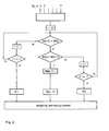
- schematically shows the procedure of a method provided in accordance with the invention.
-
Fig. 1 schematically shows asintering machine 1 on which granular or powdery substances, for example ores, are connected with each other by heating. In amaterial dump 2, the material to be heated therefore is charged onto a conveyingpath 3 formed for example as circulating grate. The conveyingpath 3 moves in the conveying direction designated by the arrow F. The material to be sintered first is passed through below anigniter 4 which ignites the material to be sintered on its surface. - During transport along the conveying
path 3, the superficially ignited material to be sintered burns through in its bed height, before it is discharged as sinter from the conveyingpath 3 through thematerial dump 5, in order to be supplied for example to a succeeding process. As soon as the material to be sintered has burnt through in its height, the sintering process is completed. The desired burn-through point D is selected in the process. Usually, the selected burn-through point D lies shortly before the end of the conveyingpath 3 and thematerial dump 5 in conveying direction F. - To promote the burn-through of the material to be sintered,
windboxes 6 are provided below the conveyingpath 3, which via asuction line 7 are connected to ablower 8 operated in suction direction. Thewindboxes 6 include suction means 9 formed as longitudinal slots, which have their largest opening on the side facing the conveyingpath 3, in order to suck in the waste gases generated during burn-through of the material to be sintered as a result of the negative pressure generated by theblower 8. Thewindboxes 6 each are arranged below the conveyingpath 3 with their suction means 9 adjacent to each other, wherein for clarity not allwindboxes 6 are shown inFig. 1 . Moreover, not all of the illustrated wind boxes with their suction means 9 are provided with reference numerals for better clarity. - In the
windboxes 6 which in conveying direction are arranged directly one beside the other before thematerial dump 5, or more exactly in their suction means 9, measurement points 10 each are arranged, not all of which are provided with reference numerals for the sake of clarity. - The measurement points 10 each include a temperature sensor arranged in the suction means 9 of a
windbox 6, which sensor measures the temperature of the waste gases sucked in from the material to be sintered on the conveying bed in the region arranged above the suction means 9. - To be able to subsequently refer to the various measurement points, the same are designated as measurement points M1 to M5. It is, however, expressly pointed out that the invention is not limited to providing exactly five measurement points 10. Rather, the skilled person can adapt their number to the respective circumstances of the
sintering machine 1, wherein in particular the last third to quarter of the conveyingpath 3 is covered with suitable measurement points 10, in order to be able to detect the burn-through point in this region of thesintering machine 1. - Via
ports 11 each provided, the measurement points M1 to M5 are connected to aregulator 12 in which the method described below takes place. In a construction unit with the regulator 12 acontroller 13 is provided, which includes anoutput 14 for specifying a conveying speed. Thisoutput 14 is connected with adrive unit 15 of the conveyingpath 3, in order to move the conveyingpath 3 in conveying direction with the conveying speed specified by thecontroller 13. Theregulator 12 and thecontroller 13 each include calculating units, possibly also a common calculating unit, which are adapted to carry out the method described below and to actuate the conveyingpath 3. - The method proposed according to the invention for adjusting the burn-through point D of the
sintering machine 1 provides that the temperatures of the waste gases each are measured at the measurement points M1 to M5. A typical temperature profile of these waste gases in a sintering machine provides that in measurement points 10 succeeding each other in conveying direction the temperature values rise, until the burn-through point D is reached. After reaching the burn-through point D, the sintered material cools down again, so that the temperature of the waste gases decreases. The temperature maximum thus is reached in the burn-through point D. In accordance with the invention, the temperature profile measured in the measurement points M1 to M5 now is analyzed, as will be explained below with reference toFig. 2 . - It is assumed that in the method a total of M1 to Mn consecutively arranged measurement points are evaluated. For this purpose, the measured temperature values of the measurement points M(i-1), M(i) and M(i+1) each are compared with each other. We begin with the second measurement point M(i=2) in conveying direction and in a first scan we check whether the temperature value of the measurement point M(i-1) is smaller than the temperature value of the measurement point M(i). If this is the case, the next check made is a comparison between the measurement points M(i) and M(i+1), wherein a maximum is noted at the position i, when the temperature value at the point M(i) is greater than the temperature value at the measurement point M(i+1). In this case, the position of the measurement point M(i) is defined as current burn-through point D(i) and the difference to the selected burn-through point D is formed. In dependence on the height of this regulation difference, the conveying speed in the
regulator 12 orcontroller 13 is adapted, wherein the adaptation for example is effected on the basis of a suitable parameterization of the regulation parameters. - When it is noted in the first scan that the temperature value of the measurement point M(i) is not greater than the temperature value of the measurement point M(i-1), the procedure goes on to the next measurement point M(i+1) and the test is repeated, until the last measurement point is reached. If also for the last measurement point the value M(i) is smaller than the measured value M(i-1), the conveying speed is increased by a constant K1, because the sequence of measured values indicates that the burn-through point lies on the conveying
path 3 before the first measurement point M1. - However, if on checking a measurement point (in the next checking step) it is noted that the succeeding measurement point M(i+1) also has a greater temperature value than the measurement point M(i), the procedure also goes on to the next measurement point, until all measurement points are processed. If this condition also is satisfied in the last measurement point, an ascending series of measured temperature values exists, which indicates that the burn-through point lies behind the conveying path. In this case, the conveying speed is reduced by a constant value K2.
- By adapting the conveying speed, the actual burn-through point D(i) is shifted in direction of the selected burn-through point D, until no more control deviation D(i)-D exists and the currently set burn-through point D(i) corresponds with the selected burn-through point D.
- This procedure will again be explained below with reference to a concrete example with respect to the arrangement as shown in
Fig. 1 . - In a first case considered, the following temperatures are measured at the measurement points M1 to M5:
M1: 240 °C M2: 250 °C M3: 260 °C M4: 270 °C M5: 280 °C - In this case, an ascending temperature sequence exists and a maximum of the temperature distribution cannot be assumed, since the temperatures each continue to rise from measurement point to measurement point. In this case, it must be assumed that the conveying speed of the
sintering machine 1 is too high and the burn-through point lies behind the conveyingpath 3. In this case, the procedure goes through the right branch of the method as shown inFig. 2 . - In a second case, the following temperature distribution exists at the measurement points M1 to M5:
M1: 250 °C M2: 260 °C M3: 270 °C M4: 260 °C M5: 250 °C - In this case, a lower temperature is measured at the measurement points M2 and M4 than at the measurement point M3. It can therefore be assumed that the current burn-through point D(i) is located at the measurement point M3. For the value i=3 the middle branch of the flow diagram of
Fig. 2 is passed through, and after determining the maximum value of the temperature at the measurement point M3 the processing of the evaluation of the measurement points is stopped. - Instead, the difference of the current burn-through point D(i) and of the selected burn-through point D is formed as control deviation. In dependence on the amount and sign of this difference forming the control deviation, a correction of the conveying speed of the
sintering machine 1 now is made. This means that the correction is the greater the further away the actual burn-through point D(i) is from the selected burn-through point. - In the above-described
case 2, the selected burn-through point D should lie at the measurement point M4, as shown inFig. 1 . The current burn-through point D(i), however, lies at the measurement point M3, so that the conveying speed is slightly increased, in order to shift the actual burn-through point D(i) to the position of the measurement point M4. - Would the actual burn-through point D(i) lie in the region of the measurement point M1, this correction would be greater.
- Would the current burn-through point D(i) lie behind the selected burn-through point D in conveying direction, the conveying speed would be decreased correspondingly.
- In connection with the determination of the conveying speed, the conveying speed of the sintering machine also can be optimized by determining the burn-through rate. In dependence on the material composition a specific burn-through rate is obtained for each sintering
machine 1, with which the sinter bed burns through in vertical direction. If this burn-through rate is known or determined, a theoretically optimum conveying speed can be calculated from the current material height of the charged material and the length of the sintering machine or in particular the distance between the ignition point of the material to be sintered on the conveying path and the selected burn-through point, with reference to the following relationship:
- When in one example the burn-through rate determined for the plant is 15 mm/min and the charged material height is 700 mm, an optimum conveying speed of 4.28 m/min is obtained with a relevant length of the sintering machine from the ignition of the material to be sintered up to the selected burn-through point. However, the values used in the example only serve the explanation and must be adapted depending on sintering machine, mode of operation and material composition.
- This theoretically determined, optimum conveying speed can be used when determining the conveying speed in connection with the provided regulation e.g. by the regulator, in order to create a stable regulation and adapt the actual conveying speed as quickly as possible to the desired mode of operation of the plant, which depends on the construction of the sintering machine and the demand of sinter for the succeeding process. Taking into account these parameters, the plant operator initially can select a suitable conveying speed. With the selected conveying speed, the material to be sintered is transported from the
material intake 2 to thematerial dump 5, wherein the surface of the sinter bed is ignited once in theigniter 4 and the ignited layer of the sinter bed is pulled down through thewindboxes 6. - By selecting the burn-through point D, the plant operator determines at which position the sinter bed should be burnt through completely. Due to the proposed regulation, a fast and exact shift of the measured or actual burn-through point D(i) to the preselected position of the burn-through point D now is effected, which position also is reached when no current burn-through point D(i) can be determined, because the current burn-through point D does not lie in the region of the measurement points M1 to M5 of the
sintering machine 1. In this case, the burn-through point initially is shifted in direction of the measurement points M1 to M5 as shown inFig. 1 , until the exact regulation takes effect. This is accomplished by an adaptation of the conveying speed by firmly specified values. - In connection with the regulation and to accelerate the passage, the optimized conveying speed for example can also be proposed to the plant operator when the amount of a difference from the currently determined burn-through point D(i) and the selected burn-through point D exceeds a certain threshold value.
-
- 1
- sintering machine
- 2
- material intake
- 3
- conveying path
- 4
- igniter
- 5
- material dump
- 6
- windbox
- 7
- suction line
- 8
- blower
- 9
- suction means
- 10
- measurement points
- 11
- port
- 12
- regulator
- 13
- controller
- 14
- output
- 15
- drive unit of the conveying path
- F
- conveying direction
- D
- burn-through point
- D(i)
- assumed burn-through point, position of the maximum measured temperature
- M1 to M5
- measurement points
Claims (12)
- A method for adjusting the burn-through point (D) in a sintering machine (1), in which the material to be sintered is charged onto a conveying path (3), ignited and transported past wind boxes (6) arranged in conveying direction (F) up to a material dump (5), wherein at at least three measurement points (10) consecutively arranged in conveying direction (F) along the conveying path (3) the temperature is measured and the conveying speed of the sintering machine (1) is adjusted in dependence on the position of the maximum measured temperature (D(i)) relative to the position of the selected burn-through point (D) on the conveying path, characterized in that the profile of the temperature of three consecutively arranged measurement points (10) is compared, wherein a maximum of the temperature is assumed when the first and third measurement points (10) in conveying direction (F) have a lower temperature value than the second measurement point (10), and wherein no maximum of the temperature is assumed when all measurement points (10) form an ascending series of temperature values, and that with an assumed maximum of the temperature the conveying speed is adjusted in dependence on a deviation between the position of the measurement point with the maximum temperature value (D(i)) and the position of the selected burn-through point (D) and that with no assumed maximum of the temperature the conveying speed is reduced by a specified value.
- The method according to claim 1, characterized in that the conveying speed is increased by a specified value when the first, second and third measurement points (10) form a descending series of temperature values.
- The method according to claim 1 or 2, characterized in that measurement points (10) are arranged in windboxes (6).
- The method according to claim 3, characterized in that a windbox (6) is divided into several segments in conveying direction (F) and in each segment a measurement point (10) is arranged.
- The method according to any of the preceding claims, characterized in that the height of the adaptation when changing the conveying speed in the case of an assumed maximum of the temperature depends on the value of the deviation between the position of the maximum of the temperature (D(i)) and the position of the selected burn-through point (D).
- The method according to any of the preceding claims, characterized in that from a plant-specific burn-through rate, the material charging height and the length of the sintering machine (1) an optimized conveying speed is determined and compared with the current conveying speed and/or taken into account when changing the conveying speed.
- The method according to claim 6, characterized in that a difference between the conveying speed and the optimum conveying speed is formed and a warning message is issued upon exceeding a threshold value.
- A regulator for adjusting the burn-through point in a sintering machine (1) with a calculating unit and at least three ports (11) for connecting temperature sensors associated to individual measurement points (10) and an output for specifying a conveying speed, characterized in that the calculating unit is adapted to carry out the method according to any of claims 1 to 7.
- The regulator according to claim 8, characterized in that the regulator (12) is integrated into a controller (13) of the sintering machine, which specifies the conveying speed of the conveying path of the sintering machine, and that the output of the regulation for specifying the conveying speed is connected to a control input of the controller.
- The regulator according to claim 8 or 9, characterized in that to the ports (11) of the regulator (12) temperature sensors are connected, which are arranged in windboxes (6) arranged in conveying direction (F) along the conveying path (3) of the sintering machine (1) and each form a measurement point (10).
- The regulator according to claim 10, characterized in that temperature sensors are arranged in suction means (9) of the windboxes (6).
- The regulator according to claim 11, characterized in that a suction means (9) is segmented in conveying direction (F) and that in several segments of the suction means (9) a temperature sensor is arranged.
Priority Applications (2)
| Application Number | Priority Date | Filing Date | Title |
|---|---|---|---|
| PL12746044T PL2737094T3 (en) | 2011-07-28 | 2012-07-19 | Method and regulator for adjusting the burn-through point in a sintering machine |
| SI201230468T SI2737094T1 (en) | 2011-07-28 | 2012-07-19 | Method and regulator for adjusting the burn-through point in a sintering machine |
Applications Claiming Priority (2)
| Application Number | Priority Date | Filing Date | Title |
|---|---|---|---|
| DE102011108747A DE102011108747A1 (en) | 2011-07-28 | 2011-07-28 | Method and controller for setting the burn-through point in a sintering machine |
| PCT/EP2012/064205 WO2013014063A1 (en) | 2011-07-28 | 2012-07-19 | Method and regulator for adjusting the burn-through point in a sintering machine |
Publications (2)
| Publication Number | Publication Date |
|---|---|
| EP2737094A1 EP2737094A1 (en) | 2014-06-04 |
| EP2737094B1 true EP2737094B1 (en) | 2015-11-25 |
Family
ID=46650503
Family Applications (1)
| Application Number | Title | Priority Date | Filing Date |
|---|---|---|---|
| EP12746044.2A Active EP2737094B1 (en) | 2011-07-28 | 2012-07-19 | Method and regulator for adjusting the burn-through point in a sintering machine |
Country Status (20)
| Country | Link |
|---|---|
| EP (1) | EP2737094B1 (en) |
| JP (1) | JP5779716B2 (en) |
| KR (1) | KR101559687B1 (en) |
| CN (1) | CN103717763B (en) |
| AP (1) | AP2014007440A0 (en) |
| AR (1) | AR087337A1 (en) |
| AU (1) | AU2012288972B2 (en) |
| BR (1) | BR112014001482A2 (en) |
| DE (1) | DE102011108747A1 (en) |
| DK (1) | DK2737094T3 (en) |
| EA (1) | EA027450B1 (en) |
| ES (1) | ES2563178T3 (en) |
| GT (1) | GT201300314A (en) |
| HU (1) | HUE027693T2 (en) |
| MX (1) | MX341481B (en) |
| PL (1) | PL2737094T3 (en) |
| SI (1) | SI2737094T1 (en) |
| UA (1) | UA108804C2 (en) |
| WO (1) | WO2013014063A1 (en) |
| ZA (1) | ZA201309255B (en) |
Cited By (1)
| Publication number | Priority date | Publication date | Assignee | Title |
|---|---|---|---|---|
| EP4345178A4 (en) * | 2021-07-12 | 2024-10-02 | JFE Steel Corporation | STATE ESTIMATION METHOD FOR SINTERING PROCESS, OPERATION GUIDANCE METHOD, METHOD FOR PRODUCING SINTERED ORE, STATE ESTIMATION DEVICE FOR SINTERING PROCESS, OPERATION GUIDANCE DEVICE, SINTERING OPERATION GUIDANCE SYSTEM, SINTERING OPERATION GUIDANCE SERVER, AND TERMINAL EQUIPMENT |
Families Citing this family (5)
| Publication number | Priority date | Publication date | Assignee | Title |
|---|---|---|---|---|
| KR101462548B1 (en) * | 2013-08-23 | 2014-11-18 | 주식회사 포스코 | Apparatus for manufacturing sintered ore and method for manufacturing sintered ore using the same |
| CN108469180B (en) * | 2018-04-09 | 2020-07-21 | 华北理工大学 | Method for establishing sintering end point prediction system based on big data and machine learning |
| JP7099433B2 (en) * | 2019-11-28 | 2022-07-12 | Jfeスチール株式会社 | Sintered ore manufacturing method |
| CN117848033A (en) * | 2022-09-30 | 2024-04-09 | 湖南中冶长天节能环保技术有限公司 | Sintering state partition detection system and method |
| WO2025093899A1 (en) | 2023-10-30 | 2025-05-08 | Arcelormittal | Method for controlling a sintering machine, associated controller and sintering machine |
Family Cites Families (8)
| Publication number | Priority date | Publication date | Assignee | Title |
|---|---|---|---|---|
| US3211441A (en) * | 1958-07-31 | 1965-10-12 | Yawata Iron & Steel Co | Method of and apparatus for automatically controlling sintering machine |
| US3211411A (en) | 1964-03-19 | 1965-10-12 | Gen Motors Corp | Vehicle seat |
| DE1209299B (en) | 1964-09-05 | 1966-01-20 | Metallgesellschaft Ag | Process for the automatic control of the belt speed of sintering machines |
| FR2265865B1 (en) * | 1974-03-27 | 1976-12-17 | Siderurgie Fse Inst Rech | |
| DE2542473C3 (en) | 1975-09-24 | 1979-03-01 | Arbed Acieries Reunies De Burbach-Eich-Dudelange S.A., Luxemburg | Process for regulating the marching speed of sintering belts when sintering fine-grained iron oxide-containing materials |
| JPS5382602A (en) * | 1976-12-28 | 1978-07-21 | Hitachi Ltd | Controlling method for position of sintering point |
| IT1116142B (en) * | 1977-10-28 | 1986-02-10 | Centro Speriment Metallurg | PERFECTED PROCESS OF CONTINUOUS AGGROMERATION OF MINERALS |
| JP4826129B2 (en) | 2005-04-27 | 2011-11-30 | Jfeスチール株式会社 | Method for producing sintered ore |
-
2011
- 2011-07-28 DE DE102011108747A patent/DE102011108747A1/en not_active Withdrawn
-
2012
- 2012-07-19 ES ES12746044.2T patent/ES2563178T3/en active Active
- 2012-07-19 CN CN201280036227.0A patent/CN103717763B/en not_active Expired - Fee Related
- 2012-07-19 BR BR112014001482A patent/BR112014001482A2/en not_active Application Discontinuation
- 2012-07-19 AP AP2014007440A patent/AP2014007440A0/en unknown
- 2012-07-19 MX MX2014000808A patent/MX341481B/en active IP Right Grant
- 2012-07-19 EP EP12746044.2A patent/EP2737094B1/en active Active
- 2012-07-19 HU HUE12746044A patent/HUE027693T2/en unknown
- 2012-07-19 DK DK12746044.2T patent/DK2737094T3/en active
- 2012-07-19 SI SI201230468T patent/SI2737094T1/en unknown
- 2012-07-19 EA EA201490075A patent/EA027450B1/en not_active IP Right Cessation
- 2012-07-19 JP JP2014522043A patent/JP5779716B2/en not_active Expired - Fee Related
- 2012-07-19 KR KR1020147004498A patent/KR101559687B1/en not_active Expired - Fee Related
- 2012-07-19 PL PL12746044T patent/PL2737094T3/en unknown
- 2012-07-19 WO PCT/EP2012/064205 patent/WO2013014063A1/en not_active Ceased
- 2012-07-19 AU AU2012288972A patent/AU2012288972B2/en not_active Ceased
- 2012-07-19 UA UAA201314805A patent/UA108804C2/en unknown
- 2012-07-26 AR ARP120102717A patent/AR087337A1/en not_active Application Discontinuation
-
2013
- 2013-12-09 ZA ZA2013/09255A patent/ZA201309255B/en unknown
- 2013-12-19 GT GT201300314A patent/GT201300314A/en unknown
Cited By (1)
| Publication number | Priority date | Publication date | Assignee | Title |
|---|---|---|---|---|
| EP4345178A4 (en) * | 2021-07-12 | 2024-10-02 | JFE Steel Corporation | STATE ESTIMATION METHOD FOR SINTERING PROCESS, OPERATION GUIDANCE METHOD, METHOD FOR PRODUCING SINTERED ORE, STATE ESTIMATION DEVICE FOR SINTERING PROCESS, OPERATION GUIDANCE DEVICE, SINTERING OPERATION GUIDANCE SYSTEM, SINTERING OPERATION GUIDANCE SERVER, AND TERMINAL EQUIPMENT |
Also Published As
| Publication number | Publication date |
|---|---|
| JP2014523971A (en) | 2014-09-18 |
| ES2563178T3 (en) | 2016-03-11 |
| AR087337A1 (en) | 2014-03-19 |
| AU2012288972B2 (en) | 2015-07-23 |
| EA201490075A1 (en) | 2014-06-30 |
| GT201300314A (en) | 2015-02-05 |
| ZA201309255B (en) | 2015-06-24 |
| SI2737094T1 (en) | 2016-03-31 |
| CN103717763B (en) | 2015-08-05 |
| UA108804C2 (en) | 2015-06-10 |
| AU2012288972A1 (en) | 2014-02-27 |
| JP5779716B2 (en) | 2015-09-16 |
| BR112014001482A2 (en) | 2017-02-14 |
| KR20140049010A (en) | 2014-04-24 |
| DK2737094T3 (en) | 2016-02-29 |
| HUE027693T2 (en) | 2016-11-28 |
| KR101559687B1 (en) | 2015-10-19 |
| MX2014000808A (en) | 2014-07-30 |
| EP2737094A1 (en) | 2014-06-04 |
| CN103717763A (en) | 2014-04-09 |
| MX341481B (en) | 2016-08-22 |
| PL2737094T3 (en) | 2016-06-30 |
| WO2013014063A1 (en) | 2013-01-31 |
| AP2014007440A0 (en) | 2014-02-28 |
| EA027450B1 (en) | 2017-07-31 |
| DE102011108747A1 (en) | 2013-01-31 |
Similar Documents
| Publication | Publication Date | Title |
|---|---|---|
| AU2012288972B2 (en) | Method and regulator for adjusting the burn-through point in a sintering machine | |
| CN103759536B (en) | A kind of sintering system and sintering indice method thereof | |
| KR102074359B1 (en) | Apparatus and Method for quality prediction | |
| KR101462548B1 (en) | Apparatus for manufacturing sintered ore and method for manufacturing sintered ore using the same | |
| US3399053A (en) | Method and apparatus for controlling sintering processes in conveyor type sintering machines | |
| JPH055589A (en) | Operating method for sintering machine | |
| CN112747591A (en) | Online detection and correction method for material running speed of roller kiln | |
| CN108955257B (en) | Control method, device and system for main exhaust fan of sintering system | |
| JP2017133764A (en) | Combustion control device and combustion control method for calcination furnace of rotary kiln with pre-heater | |
| US7536842B2 (en) | Machine and a method for filling box-like containers with articles arranged side by side and vertically | |
| CN117516148A (en) | Rare earth oxide intelligent preparation system based on data self-monitoring | |
| JPH09169422A (en) | Raw material transporting equipment | |
| KR102305734B1 (en) | Apparatus and method for controlling charging amount of sintering material | |
| JP3845592B2 (en) | Limestone preheating device and control method thereof | |
| JPH11325742A (en) | Leak detection method for sintering machine | |
| JPH06330194A (en) | Operating method of sintering machine | |
| CN104316129A (en) | Method and device for measuring consumption amount and layer thickness of hearth layer for sinter | |
| JPH08170880A (en) | Sintered ore firing method | |
| JPH1029240A (en) | Control of extrusion weight of striplike rubber material | |
| CN108955260B (en) | Control method, device and system for main exhaust fan of sintering system | |
| KR20010019060A (en) | A method of manufacturing a sintered ore | |
| KR20020046760A (en) | Equipment and method of heat-control for sinter in discharging-ore | |
| JP2658745B2 (en) | Operating method of sintering machine | |
| JPH11351551A (en) | Method and apparatus for controlling coal feeder of pulverized coal-fired boiler | |
| WO2025093899A1 (en) | Method for controlling a sintering machine, associated controller and sintering machine |
Legal Events
| Date | Code | Title | Description |
|---|---|---|---|
| PUAI | Public reference made under article 153(3) epc to a published international application that has entered the european phase |
Free format text: ORIGINAL CODE: 0009012 |
|
| 17P | Request for examination filed |
Effective date: 20131213 |
|
| AK | Designated contracting states |
Kind code of ref document: A1 Designated state(s): AL AT BE BG CH CY CZ DE DK EE ES FI FR GB GR HR HU IE IS IT LI LT LU LV MC MK MT NL NO PL PT RO RS SE SI SK SM TR |
|
| DAX | Request for extension of the european patent (deleted) | ||
| RAP1 | Party data changed (applicant data changed or rights of an application transferred) |
Owner name: OUTOTEC (FINLAND) OY |
|
| GRAP | Despatch of communication of intention to grant a patent |
Free format text: ORIGINAL CODE: EPIDOSNIGR1 |
|
| INTG | Intention to grant announced |
Effective date: 20150707 |
|
| GRAS | Grant fee paid |
Free format text: ORIGINAL CODE: EPIDOSNIGR3 |
|
| GRAA | (expected) grant |
Free format text: ORIGINAL CODE: 0009210 |
|
| AK | Designated contracting states |
Kind code of ref document: B1 Designated state(s): AL AT BE BG CH CY CZ DE DK EE ES FI FR GB GR HR HU IE IS IT LI LT LU LV MC MK MT NL NO PL PT RO RS SE SI SK SM TR |
|
| REG | Reference to a national code |
Ref country code: GB Ref legal event code: FG4D |
|
| REG | Reference to a national code |
Ref country code: CH Ref legal event code: EP |
|
| REG | Reference to a national code |
Ref country code: AT Ref legal event code: REF Ref document number: 762656 Country of ref document: AT Kind code of ref document: T Effective date: 20151215 |
|
| REG | Reference to a national code |
Ref country code: IE Ref legal event code: FG4D |
|
| REG | Reference to a national code |
Ref country code: DE Ref legal event code: R096 Ref document number: 602012012672 Country of ref document: DE |
|
| REG | Reference to a national code |
Ref country code: RO Ref legal event code: EPE |
|
| REG | Reference to a national code |
Ref country code: DK Ref legal event code: T3 Effective date: 20160223 |
|
| REG | Reference to a national code |
Ref country code: ES Ref legal event code: FG2A Ref document number: 2563178 Country of ref document: ES Kind code of ref document: T3 Effective date: 20160311 |
|
| REG | Reference to a national code |
Ref country code: SE Ref legal event code: TRGR |
|
| REG | Reference to a national code |
Ref country code: LT Ref legal event code: MG4D |
|
| REG | Reference to a national code |
Ref country code: NL Ref legal event code: FP |
|
| REG | Reference to a national code |
Ref country code: NO Ref legal event code: T2 Effective date: 20151125 |
|
| PG25 | Lapsed in a contracting state [announced via postgrant information from national office to epo] |
Ref country code: LT Free format text: LAPSE BECAUSE OF FAILURE TO SUBMIT A TRANSLATION OF THE DESCRIPTION OR TO PAY THE FEE WITHIN THE PRESCRIBED TIME-LIMIT Effective date: 20151125 Ref country code: IS Free format text: LAPSE BECAUSE OF FAILURE TO SUBMIT A TRANSLATION OF THE DESCRIPTION OR TO PAY THE FEE WITHIN THE PRESCRIBED TIME-LIMIT Effective date: 20160325 Ref country code: HR Free format text: LAPSE BECAUSE OF FAILURE TO SUBMIT A TRANSLATION OF THE DESCRIPTION OR TO PAY THE FEE WITHIN THE PRESCRIBED TIME-LIMIT Effective date: 20151125 |
|
| PG25 | Lapsed in a contracting state [announced via postgrant information from national office to epo] |
Ref country code: PT Free format text: LAPSE BECAUSE OF FAILURE TO SUBMIT A TRANSLATION OF THE DESCRIPTION OR TO PAY THE FEE WITHIN THE PRESCRIBED TIME-LIMIT Effective date: 20160325 Ref country code: RS Free format text: LAPSE BECAUSE OF FAILURE TO SUBMIT A TRANSLATION OF THE DESCRIPTION OR TO PAY THE FEE WITHIN THE PRESCRIBED TIME-LIMIT Effective date: 20151125 Ref country code: LV Free format text: LAPSE BECAUSE OF FAILURE TO SUBMIT A TRANSLATION OF THE DESCRIPTION OR TO PAY THE FEE WITHIN THE PRESCRIBED TIME-LIMIT Effective date: 20151125 |
|
| REG | Reference to a national code |
Ref country code: SK Ref legal event code: T3 Ref document number: E 20507 Country of ref document: SK |
|
| REG | Reference to a national code |
Ref country code: GR Ref legal event code: EP Ref document number: 20160400362 Country of ref document: GR Effective date: 20160505 |
|
| REG | Reference to a national code |
Ref country code: FR Ref legal event code: PLFP Year of fee payment: 5 |
|
| REG | Reference to a national code |
Ref country code: DE Ref legal event code: R097 Ref document number: 602012012672 Country of ref document: DE |
|
| PG25 | Lapsed in a contracting state [announced via postgrant information from national office to epo] |
Ref country code: EE Free format text: LAPSE BECAUSE OF FAILURE TO SUBMIT A TRANSLATION OF THE DESCRIPTION OR TO PAY THE FEE WITHIN THE PRESCRIBED TIME-LIMIT Effective date: 20151125 Ref country code: SM Free format text: LAPSE BECAUSE OF FAILURE TO SUBMIT A TRANSLATION OF THE DESCRIPTION OR TO PAY THE FEE WITHIN THE PRESCRIBED TIME-LIMIT Effective date: 20151125 |
|
| PLBE | No opposition filed within time limit |
Free format text: ORIGINAL CODE: 0009261 |
|
| STAA | Information on the status of an ep patent application or granted ep patent |
Free format text: STATUS: NO OPPOSITION FILED WITHIN TIME LIMIT |
|
| 26N | No opposition filed |
Effective date: 20160826 |
|
| REG | Reference to a national code |
Ref country code: HU Ref legal event code: AG4A Ref document number: E027693 Country of ref document: HU |
|
| REG | Reference to a national code |
Ref country code: NO Ref legal event code: MMEP |
|
| REG | Reference to a national code |
Ref country code: CH Ref legal event code: PL |
|
| REG | Reference to a national code |
Ref country code: SE Ref legal event code: EUG |
|
| GBPC | Gb: european patent ceased through non-payment of renewal fee |
Effective date: 20160719 |
|
| PG25 | Lapsed in a contracting state [announced via postgrant information from national office to epo] |
Ref country code: MC Free format text: LAPSE BECAUSE OF FAILURE TO SUBMIT A TRANSLATION OF THE DESCRIPTION OR TO PAY THE FEE WITHIN THE PRESCRIBED TIME-LIMIT Effective date: 20151125 |
|
| REG | Reference to a national code |
Ref country code: SK Ref legal event code: MM4A Ref document number: E 20507 Country of ref document: SK Effective date: 20160719 |
|
| REG | Reference to a national code |
Ref country code: GR Ref legal event code: ML Ref document number: 20160400362 Country of ref document: GR Effective date: 20170207 |
|
| PG25 | Lapsed in a contracting state [announced via postgrant information from national office to epo] |
Ref country code: CH Free format text: LAPSE BECAUSE OF NON-PAYMENT OF DUE FEES Effective date: 20160731 Ref country code: NO Free format text: LAPSE BECAUSE OF NON-PAYMENT OF DUE FEES Effective date: 20160731 Ref country code: GR Free format text: LAPSE BECAUSE OF NON-PAYMENT OF DUE FEES Effective date: 20170207 Ref country code: LI Free format text: LAPSE BECAUSE OF NON-PAYMENT OF DUE FEES Effective date: 20160731 Ref country code: HU Free format text: LAPSE BECAUSE OF NON-PAYMENT OF DUE FEES Effective date: 20160720 Ref country code: RO Free format text: LAPSE BECAUSE OF NON-PAYMENT OF DUE FEES Effective date: 20151125 Ref country code: SE Free format text: LAPSE BECAUSE OF NON-PAYMENT OF DUE FEES Effective date: 20160720 |
|
| REG | Reference to a national code |
Ref country code: IE Ref legal event code: MM4A |
|
| PG25 | Lapsed in a contracting state [announced via postgrant information from national office to epo] |
Ref country code: BG Free format text: LAPSE BECAUSE OF NON-PAYMENT OF DUE FEES Effective date: 20170228 Ref country code: SK Free format text: LAPSE BECAUSE OF NON-PAYMENT OF DUE FEES Effective date: 20160719 Ref country code: SI Free format text: LAPSE BECAUSE OF NON-PAYMENT OF DUE FEES Effective date: 20160720 Ref country code: GB Free format text: LAPSE BECAUSE OF NON-PAYMENT OF DUE FEES Effective date: 20160719 |
|
| REG | Reference to a national code |
Ref country code: SI Ref legal event code: KO00 Effective date: 20170405 |
|
| REG | Reference to a national code |
Ref country code: FR Ref legal event code: PLFP Year of fee payment: 6 |
|
| PG25 | Lapsed in a contracting state [announced via postgrant information from national office to epo] |
Ref country code: IE Free format text: LAPSE BECAUSE OF NON-PAYMENT OF DUE FEES Effective date: 20160719 |
|
| PGFP | Annual fee paid to national office [announced via postgrant information from national office to epo] |
Ref country code: CZ Payment date: 20170626 Year of fee payment: 6 |
|
| PGFP | Annual fee paid to national office [announced via postgrant information from national office to epo] |
Ref country code: NL Payment date: 20170719 Year of fee payment: 6 Ref country code: TR Payment date: 20170630 Year of fee payment: 6 |
|
| PGFP | Annual fee paid to national office [announced via postgrant information from national office to epo] |
Ref country code: IT Payment date: 20170725 Year of fee payment: 6 Ref country code: FR Payment date: 20170724 Year of fee payment: 6 Ref country code: FI Payment date: 20170720 Year of fee payment: 6 Ref country code: ES Payment date: 20170825 Year of fee payment: 6 Ref country code: DE Payment date: 20170724 Year of fee payment: 6 |
|
| PGFP | Annual fee paid to national office [announced via postgrant information from national office to epo] |
Ref country code: DK Payment date: 20170719 Year of fee payment: 6 Ref country code: BE Payment date: 20170719 Year of fee payment: 6 |
|
| REG | Reference to a national code |
Ref country code: AT Ref legal event code: UEP Ref document number: 762656 Country of ref document: AT Kind code of ref document: T Effective date: 20151125 |
|
| PG25 | Lapsed in a contracting state [announced via postgrant information from national office to epo] |
Ref country code: PL Free format text: LAPSE BECAUSE OF NON-PAYMENT OF DUE FEES Effective date: 20160719 |
|
| PG25 | Lapsed in a contracting state [announced via postgrant information from national office to epo] |
Ref country code: CY Free format text: LAPSE BECAUSE OF FAILURE TO SUBMIT A TRANSLATION OF THE DESCRIPTION OR TO PAY THE FEE WITHIN THE PRESCRIBED TIME-LIMIT Effective date: 20151125 |
|
| PG25 | Lapsed in a contracting state [announced via postgrant information from national office to epo] |
Ref country code: MT Free format text: LAPSE BECAUSE OF NON-PAYMENT OF DUE FEES Effective date: 20160731 |
|
| PGFP | Annual fee paid to national office [announced via postgrant information from national office to epo] |
Ref country code: MK Payment date: 20170622 Year of fee payment: 6 |
|
| PG25 | Lapsed in a contracting state [announced via postgrant information from national office to epo] |
Ref country code: AL Free format text: LAPSE BECAUSE OF FAILURE TO SUBMIT A TRANSLATION OF THE DESCRIPTION OR TO PAY THE FEE WITHIN THE PRESCRIBED TIME-LIMIT Effective date: 20151125 |
|
| REG | Reference to a national code |
Ref country code: DE Ref legal event code: R119 Ref document number: 602012012672 Country of ref document: DE |
|
| REG | Reference to a national code |
Ref country code: DK Ref legal event code: EBP Effective date: 20180731 |
|
| REG | Reference to a national code |
Ref country code: NL Ref legal event code: MM Effective date: 20180801 |
|
| REG | Reference to a national code |
Ref country code: BE Ref legal event code: FP Effective date: 20160212 Ref country code: BE Ref legal event code: MM Effective date: 20180731 |
|
| PG25 | Lapsed in a contracting state [announced via postgrant information from national office to epo] |
Ref country code: DE Free format text: LAPSE BECAUSE OF NON-PAYMENT OF DUE FEES Effective date: 20190201 Ref country code: FI Free format text: LAPSE BECAUSE OF NON-PAYMENT OF DUE FEES Effective date: 20180719 Ref country code: CZ Free format text: LAPSE BECAUSE OF NON-PAYMENT OF DUE FEES Effective date: 20180719 Ref country code: FR Free format text: LAPSE BECAUSE OF NON-PAYMENT OF DUE FEES Effective date: 20180731 |
|
| PG25 | Lapsed in a contracting state [announced via postgrant information from national office to epo] |
Ref country code: BE Free format text: LAPSE BECAUSE OF NON-PAYMENT OF DUE FEES Effective date: 20180731 Ref country code: NL Free format text: LAPSE BECAUSE OF NON-PAYMENT OF DUE FEES Effective date: 20180801 |
|
| PG25 | Lapsed in a contracting state [announced via postgrant information from national office to epo] |
Ref country code: IT Free format text: LAPSE BECAUSE OF NON-PAYMENT OF DUE FEES Effective date: 20180719 Ref country code: DK Free format text: LAPSE BECAUSE OF NON-PAYMENT OF DUE FEES Effective date: 20180731 |
|
| REG | Reference to a national code |
Ref country code: ES Ref legal event code: FD2A Effective date: 20190917 |
|
| PG25 | Lapsed in a contracting state [announced via postgrant information from national office to epo] |
Ref country code: ES Free format text: LAPSE BECAUSE OF NON-PAYMENT OF DUE FEES Effective date: 20180720 |
|
| PGFP | Annual fee paid to national office [announced via postgrant information from national office to epo] |
Ref country code: LU Payment date: 20200721 Year of fee payment: 9 |
|
| PGFP | Annual fee paid to national office [announced via postgrant information from national office to epo] |
Ref country code: AT Payment date: 20200722 Year of fee payment: 9 |
|
| REG | Reference to a national code |
Ref country code: AT Ref legal event code: MM01 Ref document number: 762656 Country of ref document: AT Kind code of ref document: T Effective date: 20210719 |
|
| PG25 | Lapsed in a contracting state [announced via postgrant information from national office to epo] |
Ref country code: AT Free format text: LAPSE BECAUSE OF NON-PAYMENT OF DUE FEES Effective date: 20210719 |
|
| PG25 | Lapsed in a contracting state [announced via postgrant information from national office to epo] |
Ref country code: LU Free format text: LAPSE BECAUSE OF NON-PAYMENT OF DUE FEES Effective date: 20210719 |
|
| PG25 | Lapsed in a contracting state [announced via postgrant information from national office to epo] |
Ref country code: TR Free format text: LAPSE BECAUSE OF NON-PAYMENT OF DUE FEES Effective date: 20180719 |