EP2736684B1 - Power operated rotary knife - Google Patents
Power operated rotary knife Download PDFInfo
- Publication number
- EP2736684B1 EP2736684B1 EP12818286.2A EP12818286A EP2736684B1 EP 2736684 B1 EP2736684 B1 EP 2736684B1 EP 12818286 A EP12818286 A EP 12818286A EP 2736684 B1 EP2736684 B1 EP 2736684B1
- Authority
- EP
- European Patent Office
- Prior art keywords
- blade
- blade housing
- rotary knife
- housing
- wall
- Prior art date
- Legal status (The legal status is an assumption and is not a legal conclusion. Google has not performed a legal analysis and makes no representation as to the accuracy of the status listed.)
- Active
Links
- 238000004140 cleaning Methods 0.000 claims description 47
- 239000012530 fluid Substances 0.000 claims description 19
- 238000004891 communication Methods 0.000 claims description 8
- 238000005096 rolling process Methods 0.000 description 121
- NJPPVKZQTLUDBO-UHFFFAOYSA-N novaluron Chemical compound C1=C(Cl)C(OC(F)(F)C(OC(F)(F)F)F)=CC=C1NC(=O)NC(=O)C1=C(F)C=CC=C1F NJPPVKZQTLUDBO-UHFFFAOYSA-N 0.000 description 77
- 238000005520 cutting process Methods 0.000 description 76
- 238000009966 trimming Methods 0.000 description 43
- 230000007246 mechanism Effects 0.000 description 39
- 239000000463 material Substances 0.000 description 38
- 230000000712 assembly Effects 0.000 description 35
- 238000000429 assembly Methods 0.000 description 35
- 125000006850 spacer group Chemical group 0.000 description 30
- 230000006870 function Effects 0.000 description 28
- 230000013011 mating Effects 0.000 description 28
- 239000010410 layer Substances 0.000 description 25
- 239000000047 product Substances 0.000 description 24
- 235000013372 meat Nutrition 0.000 description 23
- 230000008878 coupling Effects 0.000 description 21
- 238000010168 coupling process Methods 0.000 description 21
- 238000005859 coupling reaction Methods 0.000 description 21
- 238000000034 method Methods 0.000 description 18
- 230000033001 locomotion Effects 0.000 description 16
- 210000000988 bone and bone Anatomy 0.000 description 15
- 239000012634 fragment Substances 0.000 description 11
- 210000003813 thumb Anatomy 0.000 description 10
- 230000008901 benefit Effects 0.000 description 9
- 238000005461 lubrication Methods 0.000 description 9
- 230000002093 peripheral effect Effects 0.000 description 9
- 230000008569 process Effects 0.000 description 9
- 239000004519 grease Substances 0.000 description 8
- 230000007704 transition Effects 0.000 description 8
- 238000003780 insertion Methods 0.000 description 7
- 230000037431 insertion Effects 0.000 description 7
- 238000010411 cooking Methods 0.000 description 5
- 238000013461 design Methods 0.000 description 5
- 235000013622 meat product Nutrition 0.000 description 5
- 210000003127 knee Anatomy 0.000 description 4
- 229920000642 polymer Polymers 0.000 description 4
- 230000009471 action Effects 0.000 description 3
- 239000011324 bead Substances 0.000 description 3
- 230000007423 decrease Effects 0.000 description 3
- 230000001419 dependent effect Effects 0.000 description 3
- 238000002347 injection Methods 0.000 description 3
- 239000007924 injection Substances 0.000 description 3
- 238000003754 machining Methods 0.000 description 3
- 230000005012 migration Effects 0.000 description 3
- 238000013508 migration Methods 0.000 description 3
- 230000004048 modification Effects 0.000 description 3
- 238000012986 modification Methods 0.000 description 3
- 239000004033 plastic Substances 0.000 description 3
- 230000002028 premature Effects 0.000 description 3
- 210000001519 tissue Anatomy 0.000 description 3
- 239000010868 animal carcass Substances 0.000 description 2
- 210000000746 body region Anatomy 0.000 description 2
- 238000005266 casting Methods 0.000 description 2
- 238000010586 diagram Methods 0.000 description 2
- -1 dirt Substances 0.000 description 2
- 239000000428 dust Substances 0.000 description 2
- 230000008030 elimination Effects 0.000 description 2
- 238000003379 elimination reaction Methods 0.000 description 2
- 238000010438 heat treatment Methods 0.000 description 2
- 230000006872 improvement Effects 0.000 description 2
- 238000012423 maintenance Methods 0.000 description 2
- 239000000203 mixture Substances 0.000 description 2
- 238000012545 processing Methods 0.000 description 2
- 239000010935 stainless steel Substances 0.000 description 2
- 229910001220 stainless steel Inorganic materials 0.000 description 2
- 239000002344 surface layer Substances 0.000 description 2
- 238000010408 sweeping Methods 0.000 description 2
- 229910000851 Alloy steel Inorganic materials 0.000 description 1
- 241001456553 Chanodichthys dabryi Species 0.000 description 1
- JOYRKODLDBILNP-UHFFFAOYSA-N Ethyl urethane Chemical compound CCOC(N)=O JOYRKODLDBILNP-UHFFFAOYSA-N 0.000 description 1
- 238000009825 accumulation Methods 0.000 description 1
- 230000001154 acute effect Effects 0.000 description 1
- 229910052782 aluminium Inorganic materials 0.000 description 1
- XAGFODPZIPBFFR-UHFFFAOYSA-N aluminium Chemical compound [Al] XAGFODPZIPBFFR-UHFFFAOYSA-N 0.000 description 1
- 238000005452 bending Methods 0.000 description 1
- 230000005540 biological transmission Effects 0.000 description 1
- 239000006227 byproduct Substances 0.000 description 1
- 230000008859 change Effects 0.000 description 1
- 210000002808 connective tissue Anatomy 0.000 description 1
- 230000000994 depressogenic effect Effects 0.000 description 1
- 230000000694 effects Effects 0.000 description 1
- 238000009760 electrical discharge machining Methods 0.000 description 1
- 238000001125 extrusion Methods 0.000 description 1
- 210000003811 finger Anatomy 0.000 description 1
- 239000006260 foam Substances 0.000 description 1
- 238000005242 forging Methods 0.000 description 1
- 238000001746 injection moulding Methods 0.000 description 1
- 238000004519 manufacturing process Methods 0.000 description 1
- 229910052751 metal Inorganic materials 0.000 description 1
- 239000002184 metal Substances 0.000 description 1
- 230000000116 mitigating effect Effects 0.000 description 1
- 239000002991 molded plastic Substances 0.000 description 1
- 238000000465 moulding Methods 0.000 description 1
- 238000009740 moulding (composite fabrication) Methods 0.000 description 1
- 230000002441 reversible effect Effects 0.000 description 1
- 239000000243 solution Substances 0.000 description 1
- 238000013519 translation Methods 0.000 description 1
- 238000007514 turning Methods 0.000 description 1
- 210000000707 wrist Anatomy 0.000 description 1
Images


Classifications
-
- B—PERFORMING OPERATIONS; TRANSPORTING
- B26—HAND CUTTING TOOLS; CUTTING; SEVERING
- B26B—HAND-HELD CUTTING TOOLS NOT OTHERWISE PROVIDED FOR
- B26B25/00—Hand cutting tools involving disc blades, e.g. motor-driven
- B26B25/002—Motor-driven knives with a rotating annular blade
-
- A—HUMAN NECESSITIES
- A22—BUTCHERING; MEAT TREATMENT; PROCESSING POULTRY OR FISH
- A22B—SLAUGHTERING
- A22B5/00—Accessories for use during or after slaughtering
- A22B5/16—Skinning instruments or knives
- A22B5/165—Ring knives specially adapted for skinning
-
- A—HUMAN NECESSITIES
- A22—BUTCHERING; MEAT TREATMENT; PROCESSING POULTRY OR FISH
- A22C—PROCESSING MEAT, POULTRY, OR FISH
- A22C17/00—Other devices for processing meat or bones
- A22C17/12—Apparatus for cutting-off rind
Definitions
- the present invention relates to an annular blade housing for a power operated rotary knife and to a power operated rotary knife.
- Power operated rotary knives are widely used in meat processing facilities for meat cutting and trimming operations. Power operated rotary knives also have application in a variety of other industries where cutting and/or trimming operations need to be performed quickly and with less effort than would be the case if traditional manual cutting or trimming tools were used, e.g., long knives, scissors, nippers, etc. By way of example, power operated rotary knives may be effectively utilized for such diverse tasks as taxidermy and cutting and trimming of elastomeric or urethane foam for a variety of applications including vehicle seats.
- Power operated rotary knives typically include a handle assembly and a head assembly attachable to the handle assembly.
- the head assembly includes an annular blade housing and an annular rotary knife blade supported for rotation by the blade housing.
- the annular rotary blade of conventional power operated rotary knives is typically rotated by a drive assembly which include a flexible shaft drive assembly extending through an opening in the handle assembly.
- the shaft drive assembly engages and rotates a pinion gear supported by the head assembly.
- the flexible shaft drive assembly includes a stationary outer sheath and a rotatable interior drive shaft which is driven by a pneumatic or electric motor. Gear teeth of the pinion gear engage mating gear teeth formed on an upper surface of the rotary knife blade.
- the annular rotary blade Upon rotation of the pinion gear by the drive shaft of the flexible shaft drive assembly, the annular rotary blade rotates within the blade housing at a high RPM, on the order of 900 - 1900 RPM, depending on the structure and characteristics of the drive assembly including the motor, the shaft drive assembly, and a diameter and the number of gear teeth formed on the rotary knife blade.
- Conventional power operated rotary knives are disclosed in US 6,354,949B , US 6,751,872B , US 6,769,184B , and US 6,978,548B .
- US 2,827,657B discloses a further power operated rotary knife with an annular blade housing on which the preamble portion of claim 1 is based.
- the present invention provide an annular blade housing according to claim 1 and a power operated rotary knife according to claim 11.
- the present invention relates to an annular blade housing for a power operated rotary knife, the blade housing comprising an inner wall and an outer wall, the inner wall defining a blade housing bearing surface, the blade housing further including a cleaning port having an entry opening and exit opening, the exit opening being in the inner wall and in fluid communication with the blade housing bearing surface.
- the present invention also relates to a power operated rotary knife power operated rotary knife comprising: an annular rotary knife blade including a wall defining a knife blade bearing surface; an annular blade housing comprising an inner wall and an outer wall, the inner wall defining a blade housing bearing surface on the inner wall; a blade - blade housing bearing structure disposed between the knife blade bearing surface and the blade housing bearing surface, the blade - blade housing bearing structure supporting the knife blade for rotation with respect to the blade housing about a knife blade central axis; and the blade housing further including a cleaning port extending radially between the inner wall and the outer wall, cleaning port including an entry opening and an exit opening, the exit opening being in the inner wall and in fluid communication with the blade housing bearing surface.
- dislodged pieces or fragments of a product being cut or trimmed e.g., small pieces or fragments of fat, gristle or meat dislodged during a trimming or cutting operations
- dislodged pieces or fragments of a product being cut or trimmed e.g., small pieces or fragments of fat, gristle or meat dislodged during a trimming or cutting operations
- the cooked materials tend to gum up the blade and blade housing bearing region resulting in even more undesirable heating.
- a split ring or split annular blade housing is one that includes a split through a diameter of the blade housing.
- the split allows for expansion of a circumference of the blade housing for purposes of removing a rotary knife blade that needs to be sharpened or is at the end of its useful life and inserting a new rotary knife blade.
- a split ring blade housing has several inherent disadvantages. Because of the split, a split ring blade housing is weaker than a blade housing without a split. Further, the split, which defines a discontinuity along the rotational path of the knife blade, is often a collection point for fragments of meat, fat, gristle and/or bones that are created during a cutting or trimming operation. Accumulation of such fragment or debris in the region of the split may generate heat and/or potentially result in increased vibration of the power operated rotary knife, both of which are undesirable results.
- a split ring blade housing requires operator adjustment of the blade housing circumference as the rotary knife blade wears. Given the large loading forces applied to the blade when cutting and trimming meat, wear will occur between the bearing structure of the blade and the corresponding bearing structure of the blade housing that support the blade for rotation within the blade housing.
- the blade - blade housing bearing structure includes a portion of a radial outer surface of the rotary knife blade which serves as a bearing structure of the blade and a portion of a radial inner surface of the blade housing which serves as the corresponding or mating bearing structure of the blade housing. In such power operated rotary knifes, the outer radial surface of the blade and the corresponding radial inner surface of the blade housing will wear over time resulting in a gradual loosening of the rotary knife blade within the blade housing.
- the blade -blade housing bearing structure comprises an inwardly extending bead of the blade housing that extends into a bearing race formed in a radial outer surface of the rotary knife blade to support the blade for rotation in the blade housing.
- the bearing race of the blade and the bearing bead of the blade housing will wear over time resulting in looseness of the rotary knife blade within the blade housing.
- the power operated rotary knife will typically experience increased vibration.
- An inexperienced operator may simply accept the increased vibration of the power operated rotary knife as a necessary part of using such a knife and will reduce his or her productivity by cutting or trimming at a slower pace, turning the knife off, taking additional time between cuts, etc.
- An experienced operator may recognize that a potential solution to the problem of increased vibration is to adjust, that is, reduce the blade housing circumference, i.e., reduce the effective blade housing diameter, to account for the blade and blade housing bearing interface wear.
- Such an adjustment of the blade housing circumference is a trial and error technique that requires the operator to find a suitable operating clearance.
- Operating clearance can be viewed as striking a proper balance between providing sufficient blade - blade housing bearing clearance, that is, having the bearing diameter of the blade housing sufficiently larger than the corresponding mating bearing diameter of the knife blade such that the knife blade freely rotates in the blade housing while at the same time not having too much clearance that would cause the knife blade to have excessive play and/or vibrate in the blade housing.
- the present disclosure relates to a power operated rotary knife that addresses many of the problems associated with conventional power operated rotary knives and objectives of power operated rotary knife design.
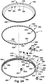
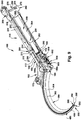
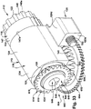
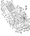
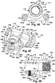
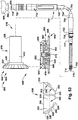
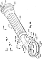
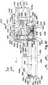
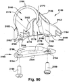
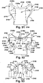
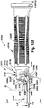
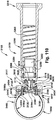
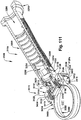
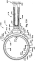
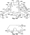
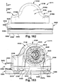
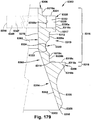
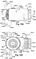
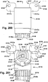
- a power operated rotary knife of the present disclosure is schematically shown generally at 100 in Figures 1-9 .
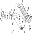
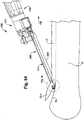
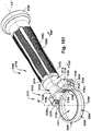
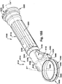
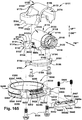
- the power operated rotary knife 100 comprises an elongated handle assembly 110 and a head assembly or head portion 111 removably coupled to a forward end of the handle assembly 110.
- the handle assembly 110 includes a hand piece 200 that is secured to the head assembly 111 by a hand piece retaining assembly 250.
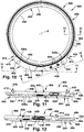
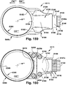
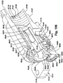
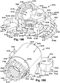
- the head assembly 111 includes a continuous, generally ring-shaped or annular rotary knife blade 300, a continuous, generally ring-shaped or annular blade housing 400, and a blade - blade housing support or bearing structure 500.
- Annular as used herein, means generally ring-like or generally ring-shaped in configuration.
- Continuous annular as used herein, means a ring-like or ring-shape configuration that is continuous about the ring or annulus, that is, the ring or annulus does not include a split extending through a diameter of the ring or annulus.
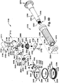
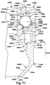
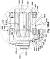
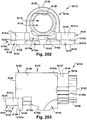
- the head assembly 111 further includes a gearbox assembly 112 and a frame or frame body 150 for securing the rotary knife blade 300 and the blade housing 400 to the gearbox assembly 112.
- the rotary knife blade 300 rotates in the blade housing 400 about a central axis of rotation R.
- the rotary knife blade 300 includes a bearing surface 319 and a driven gear 328. Both the bearing race 319 and the driven gear 328 are axially spaced from an upper end 306 of a body 302 of the blade 300 and from each other.
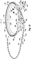
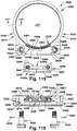
- the rotary knife blade 300 is supported for rotation in the blade housing 400 by the blade - blade housing support or bearing structure 500 of the present disclosure (best seen in Figures 2A and 14 ).
- the blade - blade housing bearing structure 500 advantageously both supports the rotary knife blade 300 for rotation with respect to the blade housing 400 and releasably secures the rotary knife blade 300 to the blade housing 400.
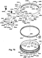
- the blade - blade housing bearing structure 500 includes an elongated rolling bearing strip 502 ( Figure 14 ) having a plurality of spaced apart rolling bearings 506 supported in a flexible separator cage 508.
- the elongated rolling bearing strip 502 is disposed in an annular passageway 504 ( Figure 13 ) formed between opposing bearing surfaces 319, 459 of the rotary knife blade 300 and the blade housing 400, respectfully.
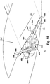
- the blade - blade housing bearing structure 500 defines a plane of rotation RP ( Figures 7 and 8 ) of the rotary knife blade 300 with respect to the blade housing 400, the rotational plane RP being substantially orthogonal to the rotary knife blade central axis of rotation R.
- the plurality of rolling bearings 506 comprises a plurality of generally spherical ball bearings.
- the plurality of ball or rolling bearings 506 are in rolling contact with and bear against the opposing bearing surfaces 319, 459 of the rotary knife blade 300 and the blade housing 400 to support the knife blade 300 for rotation with respect to the blade housing 400 and secure the knife blade 300 with respect to the blade housing 400.
- the flexible separator cage 508 rotatably supports and locates the plurality of rolling bearings 506 in spaced apart relation within the annular passageway 504.
- the flexible separator cage 508 does not function as a bearing structure or provide a bearing surface with respect to the rotary knife blade 300 and the blade housing 400.
- the flexible separator cage 508 is configured to ride in the annular passageway 504 without substantial contact with either the knife blade 300 or the blade housing 400 or the opposing bearing surfaces 319, 459 of the knife blade 300 and blade housing. Indeed, it would not be desired for the flexible separator cage 508 to be in contact with or in bearing engagement with either the rotary knife blade 300 or the blade housing 400 as this would resulting in undesirable sliding friction.
- the blade -blade housing bearing structure 500 rotatably supports the knife blade 300 with respect to the blade housing 400 via rolling bearing support provided by the plurality of ball bearings 506 of the rolling bearing strip 502 bearing against the opposing bearing surfaces 319, 459 of the rotary knife blade 300 and the blade housing 400.
- the rotational speed of a specific rotary knife blade 300 in the power operated rotary knife 100 will depend upon the specific characteristics of a drive mechanism 600 (shown schematically in Figure 53 ) of the power operated rotary knife 100, including an external drive motor 800, a flexible shaft drive assembly 700, a gear train 604, and a diameter and gearing of the rotary knife blade 300. Further, depending on the cutting or trimming task to be performed, different sizes and styles of rotary knife blades may be utilized in the power operated rotary knife 100 of the present disclosure. For example, rotary knife blades in various diameters are typically offered ranging in size from around 1.4 inches in diameter to over 7 inches in diameter. Selection of a blade diameter will depend on the task or tasks being performed.
- the rolling bearing structure of the blade - blade housing bearing structure 500 of the present disclosure results in reduced friction, less generated heat and less surface wear than would be the case with a sliding or journal bearing structure. Because of the reduced friction and heat resulting from a rolling bearing structure, the rolling blade - blade housing bearing structure 500 permits increased rotational speed of the rotary knife blade 300 compared to the sliding bearing structures disclosed or used in prior power operated rotary knives.
- Model Approx. Blade Diameter Approximate Blade Rotational Speed % Increase 1000/1500 5.0 inches 51% (930 RPM vs. 1,400 RPM) 620 2.0 inches 57% (1,400 RPM vs. 2,200 RPM)
- the flexible separator cage 508 facilitates insertion of and removal of, as a group, the plurality of rolling bearings 506 into and from the annular passageway 504. That is, it is much easier to insert the rolling bearing strip 502 into the annular passageway 504, as opposed to attempting to insert individual rolling bearings into the annular passageway 504 in a one-at-a-time, sequential order, which would be both time consuming and fraught with difficulty.
- the separator cage 508 allows for the plurality of rolling bearings 506 to be appropriately spaced to provide sufficient rolling bearing support to the rotary knife blade 300 given the application and characteristics of the product or material to be cut or trimmed with the power operated rotary knife 100, while at the same time, avoids the necessity of having more rolling bearings than required for proper bearing support of the rotary knife blade 500 and the application being performed with the power operated rotary knife 100.
- an assembled combination 550 of the rotary knife blade 300, the blade housing 400 and blade - blade housing bearing structure 500 is releasably secured as a unitary structure to the gearbox assembly 112 by the frame body 150 thereby completing the head assembly 111.
- the assembled combination 550 of the rotary knife blade 300, the blade housing 400 and blade - blade housing bearing structure 500 will hereinafter be referred to as the blade - blade housing combination 550.
- the handle assembly 110 is releasably secured to the head assembly 111 thereby completing the power operated rotary knife 100.
- a front or distal end of the power operated rotary knife 100 is an end of the knife 100 that includes the blade - blade housing combination 550 (as seen in Figure 1 ), while a rear or proximal end of the power operated rotary knife 100 is an end of the knife 100 that includes the handle assembly 110, and specifically, an enlarged end 260 of an elongated central core 252 of the hand piece retaining assembly 250 (as seen in Figure 1 ).
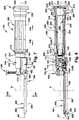
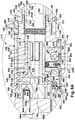
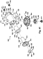
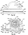
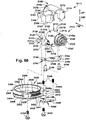
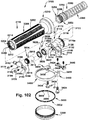
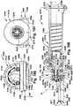
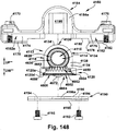
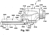
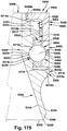
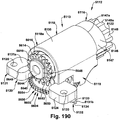
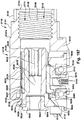
- the head assembly 111 includes the frame 150 and the gearbox assembly 112.
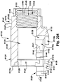
- the gearbox assembly 112 includes a gearbox housing 113 and a gearbox 602.
- the gearbox 602 is supported by the gearbox housing 113.
- the gearbox 602 includes the gear train 604 ( Figure 41 ).
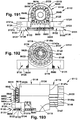
- the gear train 604 includes, in one exemplary embodiment, a pinion gear 610 and a drive gear 650.
- the gearbox 602 includes the gear train 604, along with a bearing support assembly 630 that rotatably supports the pinion gear 610 and a bearing support assembly 660 that rotatably supports the drive gear 650.
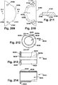
- the drive gear 650 is a double gear that includes a first bevel gear 652 and a second spur gear 654, disposed in a stacked relationship, about an axis of rotation DGR ( Figure 8A ) of the drive gear 650.
- the drive gear axis of rotation DRG is substantially parallel to the rotary knife blade axis of rotation R.
- the drive gear first bevel gear 652 meshes with the pinion gear 610 to rotatably drive the drive gear 650 about the drive gear axis of rotation DGR.
- the second spur gear 654 of the drive gear engages the driven gear 328 of the rotary knife blade 300, forming an involute gear drive, to rotate the knife blade 300 about the blade axis of rotation R.
- the gear train 604 is part of the drive mechanism 600 (shown schematically in Figure 53 ), some of which is external to the power operated rotary knife 100, that provides motive power to rotate the rotary knife blade 300 with respect to the blade housing 400.
- the drive mechanism 600 includes the external drive motor 800 and the flexible shaft drive assembly 700, which is releasably secured to the handle assembly 110 by a drive shaft latching assembly 275 ( Figure 2B ).
- the gear train 604 of the power operated rotary knife 100 transmits rotational power from a rotating drive shaft 702 of the flexible shaft drive assembly 700, through the pinion and drive gears 610, 650, to rotate the rotary knife blade 300 with respect to the blade housing 400.
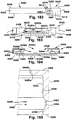
- the frame body 150 ( Figures 2C and 49 ) of the head assembly 111 includes an arcuate mounting pedestal 152 at a front or forward end of the frame body 150.
- the arcuate mounting pedestal 152 defines a seating region 152a for a mounting section 402 of the blade housing 400 such that the blade - blade housing combination 550 may be releasably affixed to the frame body 150.
- the frame body 150 also defines a cavity or opening 155 ( Figure 49 ) that slidably receives the gearbox housing 113, as the gearbox housing is moved in a forward direction FW ( Figures 3 , 7 and 45 ) along the longitudinal axis LA in the direction of the frame body 150.
- the frame body 150 releasably couples the blade - blade housing combination 550 to the gearbox housing 113 to form the head assembly 111 of the power operated rotary knife 100.
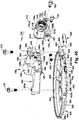
- the hand piece 200 of the handle assembly 110 is secured or mounted to the head assembly 111 by the hand piece retaining assembly 250 ( Figure 2B ) to complete the power operated rotary knife 100.
- the elongated central core 252 of the hand piece retaining assembly 250 extends through a central throughbore 202 of the hand piece 200 and threads into the gearbox housing 113 to secure the hand piece 200 to the gearbox housing 113.
- the handle assembly 110 ( Figure 2B ) extends along a longitudinal axis LA ( Figures 3 , 7 and 8 ) that is substantially orthogonal to the central axis of rotation R of the rotary knife blade 300.
- the hand piece 200 includes an inner surface 201 that defines the central throughbore 202, which extends along the handle assembly longitudinal axis LA.
- the hand piece 200 includes a contoured outer handle or outer gripping surface 204 that is grasped by an operator to appropriately manipulate the power operated rotary knife 100 for trimming and cutting operations.
- the hand piece 200 and the elongated central core 252 of the handle assembly 110 may be fabricated of plastic or other material or materials known to have comparable properties and may be formed by molding and/or machining.
- the hand piece 200 for example, may be fabricated of two over molded plastic layers, an inner layer comprising a hard plastic material and an outer layer or gripping surface comprised of a softer, resilient plastic material that is more pliable and easier to grip for the operator.
- the gearbox housing 113 and the frame body 150 of the head assembly 111 may be fabricated of aluminum or stainless steel or other material or materials known to have comparable properties and may be formed/shaped by casting and/or machining.
- the blade and blade housing 400 may be fabricated of a hardenable grade of alloy steel or a hardenable grade of stainless steel, or other material or materials known to have comparable properties and may be formed/shaped by machining, forming, casting, forging, extrusion, metal injection molding, and/or electrical discharge machining or another suitable process or combination of processes.
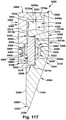
- the rotary knife blade 300 of the power operated rotary knife 100 is a one-piece, continuous annular structure.
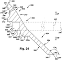
- the rotary knife blade 300 includes the body 302 and a blade section 304 extending axially from the body 302.
- the knife blade body 302 includes an upper end 306 and a lower end 308 spaced axially from the upper end 306.
- the body 302 of the rotary knife blade 300 further includes an inner wall 310 and an outer wall 312 spaced radially apart from the inner wall 310.
- An upper, substantially vertical portion 340 of the body outer wall 312 defines the knife blade bearing surface 319.
- the knife blade bearing surface 319 comprises the bearing race 320 that extends radially inwardly into the outer wall 312.
- the knife blade bearing race 320 defines a generally concave bearing surface, and, more specifically, a generally arcuate bearing face 322 in a central portion 324 of the bearing race 320.
- the knife blade bearing race 320 is axially spaced from an upper end 306 of the knife blade body 302. Specifically, a section 341 of the vertical portion 340 of the body outer wall 312 extends between the knife blade bearing race 320 and the upper end 306 of the knife blade body 302.
- the knife blade body outer wall 213 includes the vertical section 341 which separates the knife blade bearing race 320 from the upper end 306 of the knife blade body 302.
- the vertical section 341 defines a uniform diameter, cylindrical portion of the knife blade body outer wall 312 which separates the knife blade bearing race 320 from the upper end 306 of the knife blade body 302.
- the outer wall 312 of the body 302 of the rotary knife blade 300 also defines the driven gear 328.
- the driven gear 328 comprises a set of spur gear teeth 330 extending radially outwardly in a stepped portion 331 of the outer wall 312.
- the blade gear 330 is a spur gear which means that it is a cylindrical gear with a set of gear teeth 328 that are parallel to the axis of the gear, i.e., parallel to the axis of rotation R of the rotary knife blade 300 and a profile of each gear tooth of the set of gear teeth 328 includes a tip or radially outer surface 330a ( Figure 13 ) and a root or radially inner surface 330b.
- the root 330b of the gear tooth is sometimes referred to as a bottom land, while the tip 330a of the gear tooth is sometimes referred to as a top land.
- the root 330b is radially closer to the axis of rotation R of the blade 300, the root 330a and the tip 330a are radially spaced apart by a working depth plus clearance of a gear tooth of the set of gear teeth 330.
- the driven gear 328 of the rotary knife blade 300 is axially spaced from and disposed below the bearing race 320, that is, closer to the second lower end 308 of the knife blade body 302.
- the knife blade body outer wall 312 includes the vertical portion 340 which separates the set of gear teeth 330 from the upper end 306 of the knife blade body 302.
- the vertical portion 340 defines a uniform diameter, cylindrical portion of the knife blade body outer wall 213 which separates the knife blade bearing race 320 from the upper end 306 of the knife blade body 302.
- the driven gear 328 in one exemplary embodiment, defines a plurality of involute spur gear teeth 332.
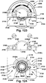
- the set of spur gear teeth 330 of the knife blade driven gear 328 are axially spaced from both the upper end 306 of the body 302 and the lower end 308 of the body 302 and are axially spaced from the arcuate bearing race 320 of the body 302. Additionally, the driven gear 328 is also offset radially inwardly with respect to the upper vertical portion 340 of the body outer wall 312 that defines the blade bearing race 320. Specifically, the set of spur gear teeth 330 are disposed radially inwardly of an outermost extent 343 of the outer wall 312 of the knife blade body 302. As can be seen in Figures 13 and 24 , the upper vertical portion 340 of the body outer wall 312 defines the outermost extent 343 of the outer wall 312.
- the upper vertical portion 340 of the outer wall 312 extends radially outwardly over the set of gear teeth 330 and form a gear tooth cap 349.
- the gear tooth cap 349 is axially spaced from and overlies the set of gear teeth 330 and functions to further protect the set of gear teeth 330.
- This configuration of the rotary knife blade 300, wherein the set of gear teeth 330 are both axially spaced from the upper end 306 of the knife blade body 302 and inwardly offset from the outermost extent 343 of the blade body outer wall 312 is sometimes referred to as a "blind gear tooth” configuration.
- the driven gear 328 of the rotary knife blade 300 of the present disclosure is in a relatively protected position with respect to the knife blade body 302.
- the driven gear 328 is in a position on the knife blade body 302 where there is less likely to be damage to the set of gear teeth 330 during handling of the rotary knife blade 300 and, during operation of the power operated rotary knife 100, there is less ingress of debris, such as small pieces fat, meat, bone and gristle generated during cutting and trimming operations, into the gear teeth region.
- the respective gear tips or radially outer surfaces 330a of the set of gear teeth 330 when the knife blade 300 is rotated, can be viewed as forming a first imaginary cylinder 336 (shown schematically in Figure 24 ).
- the respective roots or radially inner surfaces 330b of the set of gear teeth 330 when the knife blade 300 is rotated, can be viewed as forming a second imaginary cylinder 337.
- a short radially or horizontally extending portion 342 of the outer wall 312 of the blade body 302 extends between the radially outer surfaces 330a of the driven gear 328 and the vertical upper portion 340 of the outer wall 312 of the blade body.
- a second substantially vertical lower portion 344 of the outer wall 312 of the blade body 302 extends between a bottom surface 345 of the driven gear 328 and the lower end 308 of the blade body.
- the vertical lower portion 344 of the knife blade body 302 results in a radially extending projection 348 adjacent the lower end 308 of the blade body 302.
- Axial spacing of the drive gear 328 from the upper end 306 of the knife blade body 302 advantageously protects the set of gear teeth 330 from damage that they would otherwise be exposed to if, as is the case with conventional rotary knife blades, the set of gear teeth 330 were positioned at the upper end 306 of the blade body 302 of the rotary knife blade 300.
- debris is generated by the power operated rotary knife 100 during the cutting/trimming operations. Generated debris include pieces or fragments of bone, gristle, meat and/or fat that are dislodged or broken off from the product being cut or trimmed by the power operated rotary knife 100. Debris may also include foreign material, such as dirt, dust and the like, on or near a cutting region of the product being cut or trimmed.
- spacing the set of gear teeth 330 from both axial ends 306, 308 of the knife blade body 302 impedes or mitigates the migration of such debris into the region of the knife blade driven gear 328.
- Debris in the region of knife blade driven gear 328 may cause or contribute to a number of problems including blade vibration, premature wear of the driven gear 328 or the mating drive gear 650, and "cooking" of the debris.
- the rotary knife blade body 302 and the blade housing 400 are configured to provide radially extending projections or caps which provide a type of labyrinth seal to inhibit entry of debris into the regions of the knife blade driven gear 328 and the blade - blade housing bearing structure 500.
- These labyrinth seal structures are facilitated by the axial spacing of the knife blade drive gear 328 and the blade bearing race 320 from the upper and lower ends 306, 308 of the blade body 302 of the rotary knife blade 300.
- the second end 308 of the knife blade body 302 transitions radially inwardly between the body 302 and the blade section 304.
- the second end 308 of the body 302 is defined by a radially inwardly extending step or shoulder 308a.
- the blade section 304 extends from the second end 308 of the body 302 and includes a blade cutting edge 350 at an inner, lower end 352 of the blade section 304.
- the blade section 304 includes an inner wall 354 and a radially spaced apart outer wall 356.
- the inner and outer walls 354, 356 are substantially parallel.
- a bridging portion 358 at the forward end of the rotary knife blade 300 extends between the inner and outer walls 354, 356 and forms the cutting edge 350 at the intersection of the bridging portion 358 and the inner wall 354.
- the bridging portion 358 may extend generally radially or horizontally between the inner and outer walls 354, 356 or may taper at an angle between the inner and outer walls 354, 356.
- the rotary knife blade body inner wall 310 and the blade section inner wall 354 together form a substantially continuous knife blade inner wall 360 that extends from the upper end 306 to the cutting edge 350.
- the protruding region 346 provides for an increased width or thickness of the blade body 302 in the region where the bearing race 320 extends radially inwardly into the blade body outer wall 312.
- the knife blade inner wall 360 is generally frustoconical in shape, converging in a downward direction (labeled DW in Figure 24 ), that is, in a direction proceeding away from the driven gear 328 and toward the cutting edge 350.
- the knife blade inner wall 360 defines a cutting opening CO ( Figures 1 and 54 ) of the power operated rotary knife 100, that is, the opening defined by the rotary knife blade 300 that cut material, such as a cut layer CL1 ( Figure 54 ) passes through, as the power operated rotary knife 100 trims or cut a product P.
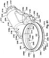
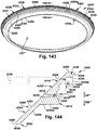
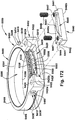
- the blade housing 400 of the power operated rotary knife 100 is a one-piece, continuous annular structure.
- the blade housing 400 includes the mounting section 402 and a blade support section 450.
- the blade housing 400 is continuous about its perimeter, that is, unlike prior split-ring annular blade housings, the blade housing 400 of the present disclosure has no split along a diameter of the housing to allow for expansion of the blade housing circumference.
- the blade - blade housing bearing or support structure 500 of the present disclosure secures the rotary knife blade 300 to the blade housing 400. Accordingly, removal of the knife blade 300 from the blade housing 400 is accomplished by removing a portion of the blade - blade housing structure 500 from the power operated rotary knife 100.
- the blade - blade housing bearing structure 500 permits use of the continuous annular blade housing 400 because there is no need to expand the blade housing circumference to remove the rotary knife blade 300 from the blade housing 400.
- the continuous annular blade housing 400 of the present disclosure provides a number of advantages over prior split-ring annular blade housings.
- the one-piece, continuous annular structure provides for greater strength and durability of the blade housing 400, as compared to prior split-ring annular blade housings.
- the fact that a circumference of the blade housing 400 is not adjustable eliminates need for and precludes the operator from adjusting the circumference of the blade housing 400 during operation of the power operated rotary knife 100 in an attempt to maintain proper operating clearance. This is a significant improvement over the prior split ring annular blade housings.
- the combination of the rotary knife blade 300, the blade housing 400 and the blade-blade housing bearing structure 500 of the power operated rotary knife 100 provide for proper operating clearance of the rotary knife blade 300 with respect to the blade housing 400 over the useful life of a given rotary knife blade.
- the blade support section extends around the entire 360 degrees (360°) circumference of the blade housing 400.
- the mounting section 402 extends radially outwardly from the blade support section 450 and subtends an angle of approximately 120°. Stated another way, the blade housing mounting section 402 extends approximately 1/3 of the way around the circumference of the blade housing 400. In the region of the mounting section 402, the mounting section 402 and the blade support section 450 overlap.
- the mounting section 402 is both axially thicker and radially wider than the blade support section 450.
- the blade housing mounting section 402 includes an inner wall 404 and a radially spaced apart outer wall 406 and a first upper end 408 and an axially spaced apart second lower end 410.
- the blade housing mounting section 402 includes two mounting inserts 420, 422 ( Figure 2A ) that extend between the upper and lower ends 408, 410 of the mounting section 402.
- the mounting inserts 420, 422 define threaded openings 420a, 422a.
- the blade housing mounting section 402 is received in the seating region 152a defined by the arcuate mounting pedestal 152 of the frame body 150 and is secured to the frame body 150 by a pair of threaded fasteners 170, 172 ( Figure 2C ).
- the pair of threaded fasteners 170, 172 extend through threaded openings 160a, 162a defined in a pair of arcuate arms 160, 162 of the frame body 150 and thread into the threaded openings 420a, 422a of the blade housing mounting inserts 420, 422 to releasably secure the blade housing 400 to the frame body 150 and, thereby, couple the blade housing 400 to the gearbox assembly 112 of the head assembly 111.
- the mounting section 402 further includes a gearing recess 424 ( Figures 25 and 28 ) that extends radially between the inner and outer walls 404, 406.
- the gearing recess 424 includes an upper clearance recess 426 that does not extend all the way to the inner wall and a wider lower opening 428 that extends between and through the inner and outer walls 404, 406.
- the upper clearance recess 426 provides clearance for the pinion gear 610 and the axially oriented first bevel gear 652 of the gearbox drive gear 650.
- the lower opening 428 is sized to receive the radially extending second spur gear 654 of the gearbox drive gear 650 and thereby provide for the interface or meshing of the second spur gear 654 and the driven gear 328 of the rotary knife blade 300 to rotate the knife blade 300 with respect to the blade housing 400.
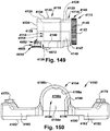
- the mounting section 402 of the blade housing 400 also includes a blade housing plug opening 429 extends between the inner and outer walls 404, 406.
- the blade housing plug opening 429 is generally oval-shaped in cross section and is sized to receive a blade housing plug 430 ( Figures 30-32 ).
- the blade housing plug 430 is removably secured to the blade housing 400 by two screws 432 ( Figure 2A ).
- the screws 432 pass through a pair of countersunk openings 434 that extend from the upper end 408 of the mounting section 402 to the lower portion 428 of the gearing recess 424 and threaded engage a pair of aligned threaded openings 438 of the blade housing plug 430.
- the blade support section 450 includes an inner wall 452 and radially spaced apart outer wall 454 and a first upper end 456 and an axially spaced second lower end 458.
- the blade support section 450 extends about the entire 360° circumference of the blade housing 400.
- the blade support section 450 in a region of the mounting section 402 is continuous with and forms a portion of the inner wall 404 of the mounting section 402.
- a portion 404a of the inner wall 404 of the mounting section 402 of the blade housing 400 within the horizontally extending dashed lines IWBS constitutes both a part of the inner wall 404 of the mounting section 402 and a part of the of the inner wall 452 of the blade support section 450.
- the dashed lines IWBS substantially correspond to an axial extent of the inner wall 452 of the blade support section 450, that is, the lines IWBS correspond to the upper end 456 and the lower end 458 of the blade support section 450.
- a substantially vertical portion 452a of the blade support section inner wall 452 adjacent the first upper end 456 defines the blade housing bearing surface 459.
- the blade housing bearing surface 459 comprises a bearing race 460 that extends radially inwardly into the inner wall 452.
- the bearing race 460 is axially spaced from the upper end 456 of the blade support section 450.
- a central portion 462 of the blade housing bearing race 460 defines a generally concave bearing surface, and, more specifically, a generally arcuate bearing face 464.
- the knife blade bearing surface 319 is concave with respect to the outer wall 312, that is, the knife blade bearing surface 319 extends into the outer wall 312 forming the bearing race 320.
- the knife blade bearing surface 319 and/or the blade housing bearing surface 459 may have a different configuration, e.g., in an alternate embodiment, the knife blade bearing surface 319 and the blade housing bearing surface 459 could, for example, be convex with respect to their respective outer and inner walls 312, 452.
- the plurality of rolling bearings 506 of the blade - blade housing bearing structure 500 would, of course, have to be configured appropriately.
- arcuate bearing faces 322, 464 for the bearing races 320, 460 of both the rotary knife blade 300 and the blade housing 400 is well suited for use with the power operated knife 100 of the present disclosure. Due to the unpredictable and varying load direction the plurality of ball bearing 506 and the arcuate bearing faces 322, 464 allow the rotary knife blade 300 and blade housing 400 to be assembled in such a way to allow for running or operating clearance.
- the arcuate shape of the blade and blade housing bearing races 320, 460 also helps compensate for manufacturing irregularities within the rotary knife blade 300 and the blade housing 400 and thereby helps maintain theoretical ideal of the single point of bearing contact between a ball bearing of the plurality of ball bearings 506 and the respective bearing races 320, 460, as discussed above, thereby reducing friction.
- a radially inner wall 440 ( Figures 2A , 30 and 31 ) of the blade housing plug 430 defines a bearing race 442 that is a portion of and is continuous with the bearing race 460 of the blade housing 400.
- a portion of the inner wall 440 of the blade housing plug 430 that would be within the horizontally extending dashed lines IWBS of Figure 29 is both a part of the inner wall 440 of the blade housing plug 430 and a part of the inner wall 452 of the blade support section 450.
- a radially outwardly extending driven gear projection or cap 466 at the lower end 458 of the blade support section 450 is axially aligned with and overlies at least a portion of the bottom surface 345 of the set of gear teeth of the knife blade driven gear 328.
- the driven gear projection or cap 466 defines the lower end 458 of the blade support section 450.
- the driven gear cap 466 overlies or bridges a gap between the first and second imaginary cylinders 336, 337 ( Figure 24 ) formed by the driven gear 328 of the rotary knife blade 300.
- the combination of the knife blade radial projection 348 and the blade housing cap 466 form a type of labyrinth seal that inhibits ingress of debris into the regions of the driven gear 328 and the bearing race 320 of the rotary knife blade 300.
- the blade support section inner wall 452 of the blade housing 400 includes a first radially outwardly extending ledge 470 that is located axially below the blade housing bearing race 460.
- the blade support section inner wall 452 also includes a second radially outwardly extending ledge 472 that forms an upper surface of the driven gear cap portion 466 and is axially spaced below the first radially outwardly extending ledge 470.
- the first and second ledges 470, 472 provide a seating regions for the horizontally extending portion 342 of the knife blade outer wall 312 and the bottom surface 345 of the set of gear teeth 330, respectively, to support the knife blade 300 when the knife blade 300 is positioned in the blade housing 400 from axially above and the rolling bearing strip 502 of the blade - blade housing bearing structure 500 has not been inserted into a passageway 504 ( Figure 13 ) between the rotary knife blade 300 and the blade housing 400 defined by opposing arcuate bearing faces 322, 464 of the knife blade bearing race 320 and the blade housing bearing race 460.
- the right tapered region 416 (as viewed from a front of the power operated rotary knife 100, that is, looking at the blade housing 400 from the perspective of an arrow labeled RW (designating a rearward direction) in Figure 25 ) of the blade housing mounting section 402 includes a cleaning port 480 for injecting cleaning fluid for cleaning the blade housing 400 and the knife blade 300 during a cleaning process.
- the cleaning port 480 includes an entry opening 481 in the outer wall 406 of the mounting section 402 and extends through to exit opening 482 in the inner wall 404 of the mounting section 402.
- a portion of the exit opening 482 in the mounting section inner wall is congruent with and opens into a region of the bearing race 460 of the blade housing 400.
- the exit opening 482 in the mounting section inner wall 404 and radial gap G ( Figure 13 ) between the blade 300 and the blade housing 400 provides fluid communication and injection of cleaning fluid into bearing race regions 320, 460 of the knife blade 300 and blade housing 400, respectively, and the driven gear 328 of the knife blade 300.
- the power operated rotary knife 100 includes the blade - blade housing support or bearing structure 500 (best seen in Figures 2A , 13 and 14 ) that: a) secures the knife blade 300 to the blade housing 400; b) supports the knife blade for rotation with respect to the blade housing about the rotational axis R; and c) defines the rotational plane RP of the knife blade.
- the blade - blade housing support structure 500 of the present disclosure permits the use of a one-piece, continuous annular blade housing 400.
- the blade - blade housing bearing structure 500 provides for lower friction between the knife blade 300 and blade housing 400 compared to prior power operated rotary knife designs.
- the lower friction afforded by the blade - blade housing bearing structure 500 advantageously permits the power operated rotary knife 100 of the present disclosure to be operated without the use of an additional, operator applied source of lubrication.
- Prior power operated rotary knives typically included a lubrication reservoir and bellows-type manual pump mechanism, which allowed the operator to inject an edible, food-grade grease from the reservoir into the blade - blade housing bearing region for the purpose of providing additional lubrication to the bearing region.
- lubrication in the nature of fat/grease typically occurs as a natural by-product or result of cutting/trimming operations, that is, as the meat product is cut or trimmed the rotary knife blade cuts through fat/grease.
- fat/grease from the meat product may migrate, among other places, into the blade - blade housing bearing region.
- the fat/grease may migrate into the annular passageway 504 ( Figure 13 ) defined by the opposing arcuate bearing faces 322, 464 of the rotary knife blade bearing race 320 and the blade housing bearing race 460 as the knife 100 is used for meat cutting/trimming operations.
- this naturally occurring lubrication would typically be supplemented by the operator by using the pump mechanism to apply additional lubrication into the blade -blade housing region in an attempt to reduce blade - blade housing bearing friction, make the blade rotate easier, and reduce heating.
- the power operated rotary knife 100 there is no reservoir of grease or manual pump mechanism to apply the grease. Elimination of the need for additional lubrication, of course, advantageously eliminates those components associated with providing lubrication (grease reservoir, pump, etc.) in prior power operated rotary knives. Elimination of components will reduce weight and/or reduce maintenance requirements associated with the lubrication components of the power operated rotary knife 100. Lower friction between the knife blade 300 and the blade housing 400 decreases heat generated by virtue of friction between the rotary knife blade 300, the blade - blade housing bearing structure 500 and the blade housing 400.
- Reducing heat generated at the blade - blade housing bearing region has numerous benefits including mitigation of the aforementioned problem of "cooking" of displaced fragments of trimmed meat, gristle, fat, and bone that migrated into the blade-blade housing bearing region 504.
- frictional contact between the blade and blade housing under certain conditions, would generate sufficient heat to "cook” material in the blade - blade housing bearing region.
- the "cooked” material tended to accumulate in the blade - blade housing bearing region as a sticky build up of material, an undesirable result.
- the lower friction afforded by the blade - blade housing bearing structure 500 of the power operated rotary knife 100 has the additional advantage of potentially increasing the useful life of one or more of the knife blade 300, the blade housing 400 and/or components of the gearbox 602.
- the useful life of any component of the power operated rotary knife 100 is dependent on proper operation and proper maintenance of the power operated knife.
- the blade-blade housing bearing structure 500 comprises an elongated rolling bearing strip 502 that is routed circumferentially through the annular passageway 504 about the axis of rotation R of the knife blade 300.
- a rotary knife bearing assembly 552 ( Figure 13 ) of the power operated rotary knife 100 includes the combination of the blade - blade housing bearing structure 500, the blade housing bearing race 460, the knife blade bearing race 320 and the annular passageway 504 defined therebetween.
- a plurality of elongated rolling bearing strips may be utilized, each similar to, but shorter in length than, the elongated bearing strip 502.
- Utilizing a plurality of shorter elongated bearing strips in place of the single, longer elongated bearing strip 502 may be advantageous in that shorter elongated bearing strips are less difficult and less expensive to fabricate. If a plurality of elongated bearing strips are used, such strips would be sequentially inserted within the annular passageway 504 in head-to-tail fashion or in spaced apart relationship.
- the plurality of elongated bearing strips may include slightly enlarged end portions so that two adjacent bearing strips do not run together or to limit an extent of overlapping of two adjacent bearing strips.
- the central portion 462 of the blade housing bearing race 460 defines, in cross section, the substantially arcuate bearing face 464.
- the central portion 324 of the knife blade bearing race 320 defines, in cross section, the substantially arcuate bearing face 322.
- the elongated rolling bearing strip 502 in one exemplary embodiment, comprises the plurality of spaced apart rolling bearings 506 supported for rotation in the flexible separator cage 508.
- the flexible separator cage 508 comprises an elongated polymer strip 520.
- the elongated polymer strip 520 defines a strip longitudinal axis SLA ( Figure 16 ) and is generally rectangular when viewed in cross section.
- the strip 520 includes a first vertical axis SVA ( Figure 15 ) that is orthogonal to the strip longitudinal axis SVA and a second horizontal axis SHA ( Figure 15 ) orthogonal to the strip longitudinal axis SLA and the first vertical axis SVA.
- the strip first vertical axis SVA is substantially parallel to a first inner surface 522 and a second outer surface 524 of the strip 520. As can be seen in Figure 15 , the first inner surface 522 and the second outer surface 524 are generally planar and parallel.
- the strip second horizontal axis SHA is substantially parallel to a third top or upper surface 526 and a fourth bottom or lower surface 528 of the strip 520.
- Each of the plurality of ball bearings 506 is supported for rotation in a respective different bearing pocket 530 of the strip 520.
- the bearing pockets 530 are spaced apart along the strip longitudinal axis SLA.
- Each of the strip bearing pockets 530 defines an opening 532 extending between the first inner surface 522 and the second outer surface 524.
- Each of the plurality of bearing pockets 530 includes a pair of spaced apart support arms 534, 536 extending into the opening 532 to contact and rotationally support a respective ball bearing of the plurality of ball bearings 506.
- the support arms 534, 536 are mirror images of each other.
- Each of the pairs of support arms 534, 536 defines a pair of facing, generally arcuate bearing surfaces that rotationally support a ball bearing of the plurality of ball bearings 506.
- Each of the pairs of support arms 534, 536 includes an extending portion 538 that extends outwardly from the strip 520 beyond the first planar inner surface 522 and an extending portion 540 that extends outwardly from the strip 520 beyond the second planar outer surface 524.
- the plurality of ball bearings 506 of the elongated rolling bearing strip 502 are in rolling contact with and provide bearing support between the knife blade bearing race 320 and the blade housing bearing race 460. At the same time, while supporting the knife blade 300 for low friction rotation with respect to the blade housing 400, the elongated rolling bearing strip 502 also functions to secure the knife blade 300 with respect to the blade housing 400, that is, the bearing strip 502 prevents the knife blade 300 from falling out of the blade housing 400 regardless of the orientation of the power operated rotary knife 100.
- the plurality of ball bearings 506 support the knife blade 300 with respect to the blade housing 400.
- the plurality of ball bearings 506 are sized that their radii are smaller than the respective radii of the arcuate bearing surfaces 464, 322.
- the radius of each of the plurality of ball bearings 506 is 1 mm. or approximately 0.039 inch, while radii of the arcuate bearing surfaces 464, 322 are slightly larger, on the order of approximately 0.043 inch.
- the radii of the plurality of ball bearings 506 may be equal to or larger than the radii of the arcuate bearing faces 464, 322. That is, the radii of the plurality of ball bearings 506 may be in a general range of between 0.02 inch and 0.07 inch, while the radii of the arcuate bearing surfaces 464, 322 may be in a general range of between 0.03 inch and 0.06 inch.
- the rolling bearing strip 502 when the rolling bearing strip 502 is inserted into the radial, annular gap G, the plurality of ball bearings 506 and a central portion 509a of the separator cage 508 are received in the annular passageway 504 defined between the opposing bearing surfaces 319, 459 of the rotary knife blade 300 and the blade housing 400.
- the annular passageway 504 comprises part of the annular gap G between the opposing outer wall 312 of the rotary knife blade body 302 and the inner wall 452 of the blade housing blade support section 450.
- the annular gap G is in a range of approximately 0.04 - 0.05 inch and is disposed between the vertical inner wall portion 452a of the blade support section 450 of the blade housing 400 and the facing vertical outer wall portion 340 of the outer wall 312 of the body 302 of the knife blade 300, adjacent or in the region of the opposing bearing surfaces 319, 459.
- the annular passageway 504 is generally circular in cross section and receives the plurality of ball bearings 506 and a central portion 509a of the separator cage 508 of the elongated rolling bearing strip 502.
- the elongated rolling bearing strip 502 and, specifically, the separator cage 508 of the rolling bearing strip 502 forms substantially a circle or a portion of a circle within the annular passageway 504 centered about an axis that is substantially congruent with the rotary knife blade axis of rotation R.
- the separator cage 508 of the rolling bearing strip 502 is vertically oriented in the gap G, the cage 508 includes top and bottom portions 509b extending from the central portion 509a.
- the top and bottom portions 509b of the separator cage 508 extend axially slightly above and slightly below the plurality of ball bearings 506.
- the elongated rolling bearing strip 502 forms substantially a circle or a portion of a circle within the annular passageway 504 centered about an axis that is substantially congruent with the rotary knife blade axis of rotation R, while the separator cage 508 forms substantially a cylinder or a portion of a cylinder with the gap G centered about the rotary knife blade axis of rotation R.
- the separator cage 508 in cross section, is rectangular and is oriented in an upright position within the gap G, the separator cage 508 may be viewed as forming substantially a cylinder or a partial cylinder within the gap G centered about the rotary knife blade axis of rotation R.
- the plurality of ball bearings 506 ride within the annular passageway 504, which is substantially circular in cross section and is centered about the blade axis of rotation R.
- the flexible separator cage 508 to be in contact with or in bearing engagement with either the rotary knife blade 300 or the blade housing 400 as this would unnecessarily generate sliding friction.
- the rotary knife blade 300 to be solely supported with respect to the blade housing 400 via rolling bearing support provided by the plurality of ball bearings 506 of the rolling bearing strip 502 bearing against the opposing arcuate bearing faces 322, 464 of the rotary knife blade 300 and the blade housing 400.
- the flexible separator cage 508 is configured to ride in the annular passageway 504 and in the annular gap G without substantial contact with either the knife blade 300 or the blade housing 400 or the opposing bearing surfaces 319, 459 of the knife blade 300 and blade housing 400.
- a width of the upper and lower portions 509b of the separator cage 508 is on the order of 0.03 inch and, as mentioned previously, the annular gap G is on the order of 0.04 - 0.05 inch.
- the separator cage 508 when the rotary knife blade 300 is rotated by the drive train 604 at a specific, desired RPM, the separator cage 508 also moves or translates in a circle along the annular gap G, although the rotational speed of the separator cage 508 within the gap G is less than the RPM of the rotary knife blade 300.
- the power operated rotary knife 100 when the power operated rotary knife 100 is in operation, the elongated rolling bearing strip 502 traverses through the annular passageway 504 forming a circle about the knife blade axis of rotation R.
- the separator cage 508 due to its movement or translation along the annular gap G about the knife blade axis of rotation R, can be considered as forming a complete cylinder within the gap G.
- the plurality of ball bearings 506 both rotate with respect to the separator cage 506 and also move or translate along the annular passageway 504 about the knife blade axis of rotation R as the separator cage 508 moves or translates along the annular gap G.
- the assembled blade - blade housing combination 550 ( Figures 9 and 10 ) is then ready to be secured, as a unit, to the frame body 150 of the head assembly 111.
- Rolling bearing strips of suitable configuration are manufactured by KMF of Germany and are available in the United States through International Customized Bearings, 200 Forsyth Dr., Ste. E, Charlotte, NC 28237-5815.
- the blade - blade housing bearing structure 500 is utilized to both secure the rotary knife blade 300 to the blade housing 400 and to rotatably support the blade 300 within the blade housing 400.
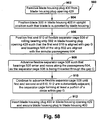
- a method of securing the rotary knife blade 300 to the blade housing 400 for rotation with respect to the blade housing 400 about the blade axis of rotation R is shown generally at 900 in Figure 58 .
- the method 900 includes the following steps. At step 902, remove the blade housing plug 430 from the blade housing plug opening 429. At step 904, position the rotary knife blade 300 in blade housing 400 in an upright position such that blade 300 is supported by blade housing 400.
- the knife blade 300 is positioned in the blade housing 400 in an upright orientation such that the horizontal extending portion 342 of the outer wall 312 of the knife blade 300 and the bottom surface 345 of the knife blade set of gear teeth 330 are disposed on the respective first and second ledges 470, 472 of the blade housing 400.
- the blade housing bearing race 460 and the knife blade bearing race 320 are substantially radially aligned such that the annular passageway 504 is defined between the blade housing bearing race 460 and the knife blade bearing race 320.
- step 906 position the first end 510 of flexible separator cage 508 of rolling bearing strip 502 in blade housing plug opening 429 such that first end 510 is tangentially aligned with the gap G between the blade 300 and the blade housing 400 and the bearings 506 of the rolling bearing strip 502 are aligned with the annular passageway 504 between the opposing arcuate bearing faces 322, 464 of the blade 300 and blade housing 400.
- step 908 advance the flexible separator cage 508 tangentially with respect to the gap G such that bearings 506 of the rolling bearing strip 502 enter and move along the passageway 504.
- the separator cage 508 is advanced such that the separator cage 508 is effectively threaded through the passageway 504 and the gap G.
- the separator cage 508 is oriented in an upright position such that the cage fits into the gap G between the knife blade 300 and the blade housing 400.
- step 910 continue to advance the flexible separator cage 508 until first and second ends 510, 512 of the separator cage 508 are substantially adjacent ( Figure 20 ), that is, the separator cage 508 forms at least a portion of a circle within the passageway 504 and the gap G (like the circle C formed by the separator cage 508 schematically shown in Figure 2A ).
- a longitudinal extent of the separator cage 508 of the elongated strip 502 along the strip longitudinal axis SLA is sufficient such that when the strip 502 is installed in the passageway 504, the first and second ends 510, 512 of the strip separator cage 508, if not in contact, are slightly spaced apart as shown, for example in Figures 2A and 14 .
- the upright strip cage 508 when installed in the passageway 504 forms at least a portion of a cylinder within the passageway 504 and the gap G.
- the elongated rolling bearing strip 502 will travel in a circular route or path of travel within the gap G, that is, the plurality of spaced apart ball bearings 506 will move in a circle though the annular passageway 504.
- the rotational speed or angular velocity of the separator cage 508 is significantly less than the rotation speed or angular velocity of the rotary knife blade 300 with respect to the blade housing 400.
- Removal of the rotary knife blade 300 from the blade housing 400 involves the reverse of the procedure discussed above. Namely, the blade housing plug 430 is removed from the blade housing 400. The rotary knife blade 300 is rotated with respect to the blade housing 400 until the adjacent ends 510, 512 of the separator cage 508 are visible within the blade housing plug opening 429.
- a small instrument such as a small screwdriver, is used to contact and direct or pry one end of the separator cage 508, say, the first end 510 of the separator cage 508, tangentially away from the gap G.
- Rotation of the rotary knife blade 300 is continued until a sufficient length of the separator cage 508 is extending tangentially away from the gap G and through the blade housing plug opening 429 such that the end 510 of the separator cage 508 may be grasped by the fingers of the operator.
- the separator cage 508 is then pulled from the gap G. Once the cage 508 has been completely removed from the gap G between the rotary knife blade 300 and the blade housing 400, the blade housing 400 is turned upside down and the rotary knife blade 300 will fall out of the blade housing 400.
- the cutting region CR of the blade - blade housing combination 550 is approximately 240° of the entire 360° periphery of the combination.
- the cutting region CR excludes the approximately 120° of the periphery of the blade - blade housing combination 550 occupied by the mounting section 402 of the blade housing 400.
- the blade - blade housing combination 550 is configured and contoured to be as smooth and continuous as practical.
- a layer L1 of material is cut or trimmed from a product P being processed (for example, a layer of tissue, for example, a layer of meat or fat trimmed from an animal carcass) by moving the power operated rotary knife 100 in a cutting direction CD such that the rotating knife blade 300 and blade housing 400 move along and through the product P to cut or trim the layer of material L1.
- the blade edge 350 cuts the layer L1 forming a cut portion CL1 of the layer L1.
- the cut portion CL1 moves along a cut or trimmed material path of travel PT through the cutting opening CO of the blade - blade housing combination 550 as the power operated rotary knife 100 advances through the product P.
- a new outer surface layer NS ( Figure 55 ) formed as the layer L1 is cut away from the product P.
- the cut portion CL1 of the layer L1 slides along the inner wall 360 of the rotary knife blade 300, while new outer surface layer NS slides along the respective outer walls 356, 454 of the blade section 350 of the knife blade 300 and the blade support section 404 of the blade housing 400.
- a smooth transition between the blade section outer wall 356 of the knife blade 300 and the blade support section outer wall 454 of the blade housing 400 is provided by the short, radially extending driven gear cap portion 466 of the blade housing 400 and the radially extending shoulder 308a of the lower end 308 of the rotary knife blade body 302.
- the close proximity of the radially extending end 467 of the driven gear cap portion 466 provides a labyrinth seal to impede ingress of foreign materials into the region of the knife blade driven gear 328 and the region of the blade - blade housing bearing structure 500.
- the blade - blade housing combination 550 in the cutting region CR is shaped to extent possible to reduce drag and friction experienced by the operator when manipulating the power operated rotary knife in performing cutting or trimming operations.
- the drive mechanism 600 of the power operated rotary knife 100 includes certain components and assemblies internal to the power operated rotary knife 100 including the gear train 604 and the driven gear 328 of the rotary knife blade 300 and certain components and assemblies external to the power operated rotary knife 100 including the drive motor 800 and the flexible shaft drive assembly 700, which is releasably coupled to the knife 100, via the drive shaft latching assembly 275.
- the drive mechanism 600 includes the gearbox 602 comprising the gear train 604.
- the gear train 604 includes the pinion gear 610 and the drive gear 650.
- the drive gear 650 engages the driven gear 328 of the rotary knife blade 300 to rotate the knife blade 300.
- the gearbox drive gear 650 in one exemplary embodiment, is a double gear that includes an upper, vertically or axially oriented bevel gear 652 and a lower, horizontally or radially oriented spur gear 654.
- the drive gear upper bevel gear 652 engages and is rotatably driven by the pinion gear 610.
- the drive gear lower spur gear 654 defines a plurality of drive gear teeth 656 that are mating involute gear teeth that mesh with the involute gear teeth 332 of the rotary knife blade driven gear 328 to rotate the rotary knife blade 300.
- This gearing combination between the drive gear 650 and the rotary knife blade 300 defines a spur gear involute gear drive 658 ( Figure 8A ) to rotate the rotary knife blade 300.
- the profiles of the rotary knife gear teeth 332 of the rotary knife blade 300 and the gear teeth 656 of the spur gear 654 of the drive gear 650 are involutes of a circle and contact between any pair of gear teeth occurs at a substantially single instantaneous point.
- Rotation of the drive gear 650 and the knife blade driven gear 328 causes the location of the contact point to move across the respective tooth surfaces.
- the motion across the respective gear tooth faces is a rolling type of contact, with substantially no sliding involved.
- the involute tooth form of rotary knife blade gear teeth 332 and the spur gear gear teeth 656 results in very little wear of the respective meshing gear teeth 332, 656 versus a gearing structure wherein the meshing gear teeth contact with a sliding motion.
- the involute gear drive 658 is also a spur gear drive which means that an axis of rotation DGR (shown in Figures 8 and 8A ) of the drive gear 650 is substantially parallel to the axis of rotation R of the knife blade 300.
- DGR shown in Figures 8 and 8A
- Such a spur drive with parallel axes of rotation DGR, R is very efficient in transmitting driving forces.
- the spur drive gearing arrangement of the rotary knife blade gear teeth 332 and the spur gear drive teeth 656 also advantageously contributes to reducing the wear of the meshing gears 332, 656 compared with other more complex gearing arrangements.
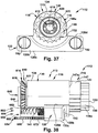
- the pinion gear 610 comprises an input shaft 612 and a gear head 614 that extends radially outwardly from the input shaft 612 and defines a set of bevel gear teeth 616.
- the input shaft 612 extends in a rearward direction RW along the handle assembly longitudinal axis LA and includes a central opening 618 extending in a forward direction FW from a rearward end 629 ( Figure 41 ) to a forward end 628 of the input shaft 612, the central opening 618 terminating at the gear head 614.
- An inner surface 620 of the input shaft 612 defines a cross-shaped female socket or fitting 622 ( Figures 37 and 40 ) which receives a mating male drive fitting 714 ( Figure 53 ) of the shaft drive assembly 700 to rotate the pinion gear 610 about an axis of rotation PGR which is substantially congruent with the handle assembly longitudinal axis LA and intersects the knife blade axis of rotation R.
- the pinion gear 610 is supported for rotation about the pinion gear axis of rotation PGR ( Figures 8 and 8A ) by the bearing support assembly 630, which, in one exemplary embodiment, includes a larger sleeve bushing 632 and a smaller sleeve bushing 640 ( Figure 42 ).
- a forward facing surface 624 of the gear head 614 of the pinion gear 610 includes a central recess 626 which is substantially circular in cross section and is centered about the pinion gear axis of rotation PGR.
- the pinion gear central recess 626 receives a cylindrical reward portion 642 of the smaller sleeve bushing 640.
- the smaller sleeve bushing 640 functions as a thrust bearing and includes an enlarged annular head 644 provides a bearing surface for the pinion gear gear head 614 and limits axial travel of the pinion gear 610 in the forward direction FW, that is, travel of the pinion gear 610 along the pinion gear axis of rotation PGR, in the forward direction FW.
- the sleeve bushing 640 is supported on a boss 158b ( Figures 49 and 50 ) of the frame body 150. Specifically, the boss 158b extends rearwardly from an inner surface 158a of a forward wall 154a of a central cylindrical region 154 of the frame body 150.
- the boss 158b of the frame body central cylindrical region 154 includes a flat 158c that interfits with a flat 648 ( Figure 2C ) formed in a central opening 646 of the sleeve bushing 640 to prevent rotation of the sleeve bushing 640 as the pinion gear 610 rotates about its axis of rotation PGR.
- the gear head 614 of the pinion gear 610 includes 25 bevel gear teeth and, at the forward facing surface 624, has an outside diameter of approximately 0.84 inch (measured across the gear from the tops of the gear teeth) and a root diameter of approximately 0.72 inch (measured across a base of the teeth).
- the bevel gear teeth 616 taper from a larger diameter at the forward facing surface 624 to a smaller diameter in away from the forward facing surface 624.
- the larger sleeve bushing 632 of the pinion gear bearing support assembly 630 includes a central opening 634 that receives and rotatably supports the pinion gear input shaft 612.
- the larger sleeve bushing 632 includes an enlarged forward head 636 and a cylindrical rearward body 637.
- the cylindrical rearward body 637 of the larger sleeve bushing 632 is supported within a conforming cavity 129 ( Figures 39 and 48 ) of the inverted U-shaped forward section 118 of the gearbox housing 113, while the enlarged forward head 636 of the sleeve bushing 632 fits within a conforming forward cavity 126 of the U-shaped forward section 118 of the gearbox housing 113.
- the cylindrical body 639 of the larger sleeve bushing 632 defining the central opening 634 provides radial bearing support for the pinion gear 610.
- the enlarged head 636 of the sleeve bushing 632 also provides a thrust bearing surface for the rearward collar 627 of the gear head 614 to prevent axial movement of the pinion gear 610 in the rearward direction RW, that is, travel of the pinion gear 610 along the pinion gear axis of rotation PGR, in the rearward direction RW.
- the bearing support assembly 630 for the pinion gear 610 may comprise one or more roller or ball bearing assemblies or a combination of roller/ball bearing assemblies and sleeve bearings.
- the drive gear 650 in one exemplary embodiment, is a double gear with axially aligned gears including the first bevel gear 652 and the second spur gear 654, both rotating about a drive gear axis of rotation DGR ( Figure 8 and 8A ).
- the drive gear axis of rotation DGR is substantially orthogonal to and intersects a pinion gear axis of rotation PGR. Further, the drive gear axis of rotation DGR is substantially parallel to the knife blade axis of rotation R.
- the first gear 652 is a bevel gear and includes a set of bevel gear teeth 653 that mesh with the set of bevel gear teeth 616 of the gear head 614 of the pinion gear 610. As the pinion gear 610 is rotated by the shaft drive assembly 700, the bevel gear teeth 616 of the pinion gear 610, in turn, engage the bevel gear teeth 653 of the first gear 652 to rotate the drive gear 650.
- the second gear 654 comprises a spur gear including a set of involute gear teeth 656.
- the spur gear 654 engages and drives the driven gear 328 of the knife blade 300 to rotate the knife blade about its axis of rotation R. Because the spur gear 654 of the gearbox 602 and the driven gear 328 of the knife blade 300 have axes of rotation DGR, R that are parallel (that is, a spur gear drive) and because the gears 654, 328 comprise an involute gear drive 658, there is less wear of the respective gear teeth 656, 332 than in other gear drives wherein the axes of rotation are not parallel and wherein a non-involute gear drive is used.
- the first gear 652 includes 28 bevel gear teeth and has an outside diameter of approximately 0.92 inch and an inside diameter of approximately 0.66 inch and the second gear 654 includes 58 spur gear teeth and has an outside diameter of approximately 1.25 inches and a root diameter of approximately 1.16 inches.
- the drive gear 650 is supported for rotation by the bearing support assembly 660 ( Figures 39-43 ).
- the bearing support assembly 660 in one exemplary embodiment, comprises a ball bearing assembly 662 that supports the drive gear 650 for rotation about the drive gear rotational axis DGR.
- the drive gear bearing support assembly 660 is secured to a downwardly extending projection 142 ( Figures 47 and 48 ) of the inverted U-shaped forward section 118 of the gearbox housing 113.
- the ball bearing assembly 662 includes a plurality of ball bearings 666 trapped between an inner race 664 and an outer race 668.
- the outer race 668 is affixed to the drive gear 650 and is received in a central opening 670 of the drive gear 650.
- the inner race 664 is supported by the fastener 672.
- a threaded end portion of the fastener 672 and screws into a threaded opening 140 ( Figures 41 and 47 ) defined in a stem 143 of the downwardly extending projection 142 of the inverted U-shaped forward section 118 of the gearbox housing 113.
- the fastener 672 secures the ball bearing assembly 662 to the gearbox housing 113.
- the bearing support assembly 660 may comprise one or more sleeve bearings or bushings.
- the gearbox assembly 112 includes the gearbox housing 113 and the gearbox 602.
- the gearbox housing 113 includes a generally cylindrical rearward section 116 (in the rearward direction RW away from the blade housing 400), an inverted U-shaped forward section 118 (in the forward direction FW toward the blade housing 400) and a generally rectangular base section 120 disposed axially below the forward section 118.
- the gearbox housing 113 includes the gearbox cavity or opening 114 which defines a throughbore 115 extending through the gearbox housing 113 from a rearward end 122 to a forward end 124.
- the throughbore 115 extends generally along the handle assembly longitudinal axis LA.
- the inverted U-shaped forward section 118 and the cylindrical rearward section 116 combine to define an upper surface 130 of the gearbox housing 113.
- the gearbox housing 113 also includes a generally rectangular shaped base 120 which extends downwardly from the inverted U-shaped forward section 118, i.e., away from the upper surface 130.
- the rectangular base 120 includes a front wall 120a and a rear wall 120b, as well as a bottom wall 120c and an upper wall 120d, all of which are generally planar.
- first and second arcuate recesses 120e, 120f are first and second arcuate recesses 120e, 120f.
- the first arcuate recess 120e is an upper recess, that is, the upper recess 120e is adjacent a bottom portion 141 of the inverted U-shaped forward section 118 and, as best seen in Figure 43 , is offset slightly below the upper wall 120d of the rectangular base 120.
- the second arcuate recess 120f is a lower recess and extends through the bottom wall 120c of the rectangular base 120.
- the bottom portion 141 of the inverted U-shaped forward section 118 includes a downwardly extending projection 142 ( Figure 47 ).
- the downwardly extending projection 142 includes a cylindrical stem portion 143 and defines a threaded opening 140 extending through the projection 142.
- a central axis through the threaded opening 140 defines and is coincident with the axis of rotation DGR of the drive gear 650.
- the upper and lower arcuate recesses 120e, 120f are centered about the drive gear axis of rotation DGR and the central axis of the threaded opening 140.
- the throughbore 115 of the gearbox housing 113 provides a receptacle for the pinion gear 610 and its associated bearing support assembly 630 while the upper and lower arcuate recesses 120e, 120f provide clearance for the drive gear 650 and its associate bearing support assembly 660.
- the cylindrical body 637 of the larger sleeve bushing 632 fits within the cylindrical cavity 129 of the inverted U-shaped forward section 118.
- the enlarged forward head 636 of the sleeve bushing 632 fits within the forward cavity 126 of the forward section 118.
- the cylindrical cavity 129 and the forward cavity 126 of the inverted U-shaped forward section 118 are both part of the throughbore 115.
- the upper recess 120e provides clearance for the first bevel gear 652 of the drive gear 650 as the drive gear 650 rotates about its axis of rotation DGR upon the first bevel gear 652 being driven by the pinion gear 610.
- the wider lower recess 120f provides clearance for the second spur gear 654 of the drive gear 650 as the spur gear 654 coacts with the driven gear 328 to rotate the rotary knife blade 300 about its axis of rotation R.
- the downwardly extending projection 142 and stem 143 provide seating surfaces for the ball bearing assembly 662, which supports the drive gear 650 for rotation within the rectangular base 120 of the gearbox housing 113.
- a cleaning port 136 extends through the bottom portion 141 of inverted U-shaped forward section 118 and a portion of the base 120 of the gearbox housing 113 to allow cleaning fluid flow injected into the throughbore 115 of the gearbox housing 113 from the proximal end 122 of the gearbox housing 113 to flow into the upper and lower arcuate recesses 120e, 120f for purpose of cleaning the drive gear 650.
- an inner surface 145 of the cylindrical rearward section 116 of the gearbox housing 113 defines a threaded region 149, adjacent the proximal end 122 of the gearbox housing 113.
- the threaded region 149 of the gearbox housing 113 receives a mating threaded portion 262 ( Figure 2B ) of the elongated central core 252 of the hand piece retaining assembly 250 to secure the hand piece 200 to the gearbox housing 113.
- an outer surface 146 of the cylindrical rearward section 116 of the gearbox housing 113 defines a first portion 148 adjacent the proximal end 122 and a second larger diameter portion 147 disposed forward or in a forward direction FW of the first portion 148.
- the first portion 148 of the outer surface 146 of the cylindrical rearward portion 116 of the gearbox housing 113 includes a plurality of axially extending splines 148a.
- the plurality of splines 148a accept and interfit with four ribs 216 ( Figure 2B ) formed on an inner surface 201 of a distal end portion 210 of the hand piece 200.
- the coacting plurality of splines 148a of the gearbox housing 113 and the four ribs 216 of the hand piece 200 allow the hand piece 200 to be oriented at any desired rotational position with respect to the gearbox housing 113.
- the second larger diameter portion 147 of the outer surface 146 of the cylindrical rearward section 116 of the gearbox housing 113 is configured to receive a spacer ring 290 ( Figure 2B ) of the hand piece retaining assembly 250.
- the spacer ring 290 abuts and bears against a stepped shoulder 147a defined between the cylindrical rearward section 116 and the inverted U-shaped forward section 118 of the gearbox housing 113. That is, an upper portion 134 of the inverted U-shaped forward section 118 is slightly radially above a corresponding upper portion 132 of the cylindrical rearward section 116 of the gearbox housing 113.
- a rear or proximal surface 292 ( Figure 2B ) of the spacer ring 290 acts as a stop for an axially stepped collar 214 of the distal end portion 210 of the hand piece 200 when the hand piece 200 is secured to the gearbox housing 113 by the elongated central core 252 of the hand piece retaining assembly 250.
- the second larger diameter portion 147 of the outer surface 146 also includes a plurality of splines (seen in Figures 41 and 46 ).
- the plurality of splines of the second portion 147 are used in connection with an optional thumb support (not shown) that may be used in place of the spacer ring 290.
- the thumb support provides an angled, outwardly extending support surface for the operator's thumb.
- the plurality of splines of the second portion 149 are utilized in connection with the optional thumb support to allow the operator to select a desired rotational orientation of the thumb support with respect to the gearbox housing 113 just as the plurality of splines 148a of the first portion 148 allow the operator to select a desired rotational orientation of the hand piece 200 with respect to the gearbox housing 113.
- the frame body 150 receives and removably supports both the gearbox assembly 112 and the blade - blade housing combination 550. In this way, the frame body 150 releasably and operatively couples the gearbox assembly 112 to the blade - blade housing combination 550 such that the gear train 604 of the gearbox assembly 112 operatively engages the driven gear 328 of the rotary knife blade 300 to rotate the knife blade 300 with respect to the blade housing 400 about the axis of rotation R.
- the frame body 150 includes the arcuate mounting pedestal 152 disposed at a forward portion 151 ( Figure 2C ) of the frame 150, the central cylindrical region 154, and a rectangular base 180 ( Figure 48 ) disposed below the central cylindrical region 154.
- the arcuate mounting pedestal 152 of the frame body defines the seating region 152a ( Figures 22C and 51 ) to receive the mounting section 402 of the blade housing 400 and secure the blade - blade housing combination 550 to the frame body 150.
- the central cylindrical region 154 and the rectangular base 180 of the frame body 150 define a cavity 155 ( Figures 45 and 49 ) which slidably receives the gearbox housing 113.
- the frame body cavity 155 is comprised of an upper socket 156 defined by the central cylindrical region 154 and a lower horizontally extending opening 190 defined by and extending through the central rectangular base 180.
- the central rectangular base 180 of the frame body 150 includes a bottom wall 182 and a pair of side walls 184 that extend upwardly from the bottom wall 182. As is best seen in Figures 49 and 50 , a pair of bosses 186 extend inwardly from the pair of side walls 184. Rearward facing surfaces 187 of the pair of bosses 186 each include a threaded opening 188.
- the lower horizontally extending opening 190 defined by the rectangular base 180 includes two parts: a generally rectangular portion 190a extending rearwardly from the pair of boss surfaces 187; and a forward portion 190b that extends through the rectangular base 180 to the seating region 152a of the frame body 150.
- the gearbox assembly 112 is aligned with and moved toward a proximal end 157 of the frame body 150.
- the socket 156 defined by the central cylindrical region 154 of the frame body 150 is configured to slidably receive the inverted U-shaped forward section of the gearbox housing 113 and the rectangular portion 190a of the horizontally extending opening 190 of the rectangular base 180 is configured to slidably receive the rectangular base 120 of the gearbox housing 113.
- the upper surface 130 of the gearbox housing 113 is slidably received within the inner surface 158 of the central cylindrical region 154 of the frame body 150.
- the front wall 120a of the base 120 of the gearbox housing 113 abuts the rearward facing surfaces 187 of the pair of bosses 186 of the rectangular base 180 of the frame body 150. Further, the horizontally extending openings 121 of the gearbox housing base 120 are aligned with the horizontally extending threaded openings 188 of the pair of bosses 186 of the frame body rectangular base 180.
- a pair of threaded fasteners 192 ( Figure 45 ) pass through the openings 121 of the gearbox housing base 120 and thread into the threaded openings 188 of the pair of bosses 186 of the frame body rectangular base 180 to releasably secure the gearbox assembly 112 to the frame body 150.
- the openings 121 of the gearbox housing base 180 are partially threaded to prevent the fasteners 192 from fall out of the openings 121 when the gearbox housing 113 is not coupled to the frame body 150.
- the openings 121 of the gearbox housing base 120 include countersunk end portions 121a ( Figure 45 ) to receive the enlarged heads of the pair of threaded fasteners 192 such that the enlarged heads of the fasteners 192, when tightened into the frame body 150, are flush with the rear wall 120b of the base 120.
- the threaded fasteners 192 include narrow body portions relative to the enlarged heads and larger diameter threaded portions such that the fasteners 192 remain captured within their respective gearbox housing openings 121 when the gearbox housing 113 is not coupled to the frame body 150.
- Relative movement between the gearbox assembly 112 and the frame body 150 is constrained by the threaded interconnection of the gearbox housing 113 to the frame body 150 via the threaded fasteners 192 and the abutting surfaces of the rectangular base 120 of the gearbox housing 113 and the rectangular base 180 of the frame body 150.
- the frame body 150 releasably receives the blade - blade housing combination 550 and thereby operatively couples the blade - blade housing combination 550 to the gearbox assembly 112.
- the pair of arcuate arms 160, 162 of the frame body 150 define the arcuate mounting pedestal 152.
- the mounting pedestal 152 defines the seating region 152a that releasably receives the mounting section 402 of the blade housing 400.
- the arcuate mounting pedestal 152 includes an inner wall 174, an upper wall 176 extending radially in the forward direction FW from an upper end of the inner wall 174, and a lower wall or ledge 178 extending radially in a forward direction FW from a lower end of the inner wall 174.
- the respective threaded fasteners 170, 172 of the frame body 150 are threaded into the threaded openings 420a, 422a of the mounting inserts 420, 422 of the blade housing mounting section 402 to secure the combination blade - blade housing 550 to the frame body 150.
- the gearbox assembly 112 is coupled to the frame body 150, when the blade - blade housing combination 550 is secured to the frame body 150, the second spur gear 654 of the drive gear 650 of the gearbox assembly 112 engages and meshes with the driven gear 328 of the rotary knife blade 300 of the blade - blade housing combination 550.
- the gear train 604 of the gearbox assembly 112 is operatively engaged with the driven gear 328 of the rotary knife blade 300 to rotatably drive the blade 300 within the blade housing 400 about the blade axis of rotation R.
- the threaded fasteners 170, 172 of the frame body 150 include narrow bodies and larger diameter threaded portions such that the fasteners remain captured in the partially threaded openings 160a, 162a of the arcuate arms 160, 162.
- the pair of threaded fasteners 170, 172 of the frame body 150 are unthreaded from the threaded openings 420a, 420b of the blade housing mounting inserts 420, 422. Then, the blade - blade housing combination 550 is moved is the forward direction FW with respect to the frame body 150 to disengage the blade -blade housing combination 550 from the head assembly 111.
- a forward wall 154a of the central cylindrical region 154 of the frame body 150 includes a projection 198 that supports a steeling assembly 199 ( Figure 2C ).
- the steeling assembly 199 includes a support body 199a, spring biased actuator 199b, and a push rod 199c with a steeling member 199d affixed to a bottom of the push rod 199c.
- the steeling assembly support body 199a is affixed to the projection 198.
- the handle assembly 110 includes the hand piece 200 and the hand piece retaining assembly 250.
- the hand piece 200 includes the inner surface 201 and the outer gripping surface 204.
- the inner surface 201 of the hand piece 200 defines the axially extending central opening or throughbore 202.
- the outer gripping surface 204 of the hand piece 200 extends between an enlarged proximal end portion 206 and the distal end portion 210.
- a front face or wall 212 of the hand piece 200 includes an axially stepped collar 214 that is spaced rearwardly and serves an abutment surface for a spacer ring 290 of the hand piece retaining assembly 250.
- the inner surface 201 of the hand piece 200 defines the four ribs 216, as previously described, which permit the hand piece 200 to be oriented in any desired rotational position with respect to the gearbox housing 113.
- a slotted radial opening 220 in the front face 212 of the hand piece 200 receives an optional actuation lever (not shown).
- the optional actuation lever if used, allows the operator to actuate the power operated rotary knife 100 by pivoting the lever toward the gripping surface 204 thereby engaging the drive mechanism 600 to rotatably drive the rotary knife blade 300.
- the hand piece retaining assembly 250 releasably secures the hand piece 200 to the gearbox housing 113.
- the hand piece retaining assembly 250 includes the elongated central core 252 which extends through the central opening 202 of the hand piece 200.
- the elongated core 252 threads into the threaded opening 149 ( Figure 48 ) at the proximal or rearward end 122 of the gearbox housing 113 to secure the hand piece 200 to the gearbox housing 113.
- the hand piece retaining assembly 250 also includes the spacer ring 290 ( Figure 2B ).
- the spacer ring 290 When the hand piece 200 is being secured to the gearbox housing 113, the spacer ring 290 is positioned on the second cylindrical portion 147 ( Figure 48 ) of the outer surface 146 of the cylindrical rearward section 116 of the gearbox housing 113.
- the spacer ring 290 is positioned to abut the stepped shoulder 147a defined between the larger second portion 147 of the outer surface 146 of the cylindrical rearward portion 116 and the inverted U-shaped forward section 118 of the gearbox housing 113.
- the spacer ring 290 When the hand piece 200 is secured to the gearbox housing 113 by the elongated central core 252, the spacer ring 290 is sandwiched between the hand piece 200 and the stepped shoulder 147a of the gearbox housing 113.
- the elongated central core 252 of the hand piece retaining assembly 250 includes an inner surface 254 and an outer surface 256 extending between a distal or forward reduced diameter end portion 264 and the enlarged proximal or rearward end portion 260.
- the inner surface 254 of the elongated central core 252 defines a throughbore 258 extending along the longitudinal axis LA of the handle assembly 110.
- the elongated central core 252 also includes a threaded portion 262 on the outer surface 256 at the forward reduced diameter end portion 264.
- the outer surface 256 of the elongated core 252 includes a radially outwardly stepped shoulder 265.
- the hand piece 200 is secured to the gearbox housing 113. Specifically, the hand piece 200 is prevented from moving in the forward axial direction FW along the handle assembly longitudinal axis LA by the spacer ring 290.
- the rear surface 292 of the spacer ring 290 acts as a stop for the axially stepped collar 214 of the distal end portion 210 of the hand piece 200 to prevent movement of the hand piece 200 in the forward direction FW.
- the hand piece 200 is prevented by moving in the rearward axial direction RW along the handle assembly longitudinal axis LA by the radially outwardly stepped shoulder 265 of the elongated central core 252.
- the stepped shoulder 265 of the elongated central core 252 bears against a corresponding inwardly stepped shoulder 218 of the hand piece 200 to prevent movement of the hand piece 200 in the rearward direction RW.
- the spacer ring 290 may be replaced by an optional operator thumb support.
- a strap attachment bracket (not shown) may be disposed between the spacer ring 290 and the gearbox housing 113. The strap attachment bracket, if used, provides an attachment point for an optional operator wrist strap (not shown).
- the elongated central core 252 of the hand piece retaining assembly 250 includes the enlarged rearward or proximal end portion 260.
- the enlarged end portion 260 supports a drive shaft latching assembly 275 which engages a first coupling 710 ( Figures 1 and 53 ) of an outer sheath 704 of the shaft drive assembly 700 to secure the outer sheath 704 of the shaft drive assembly 700 to the handle assembly 110 and thereby ensures operative engagement of a first male fitting 714 of the inner drive shaft 702 within the female socket 622 of the pinion gear input shaft 612.
- the inner surface 254 of the elongated central core 252 also includes an inwardly stepped shoulder 266 ( Figure 8 ) that provides a stop for a distal portion 711 of the first coupling 710 of the shaft drive assembly 700.
- the enlarged rearward end portion 260 of the elongated central core 252 of the hand piece retaining assembly 250 defines a generally U-shaped slot 268 that extends partially through the end portion 260 in a direction orthogonal to the longitudinal axis LA of the handle assembly 110.
- the rearward end portion 260 also defines a central opening 270 ( Figure 8 ) that is aligned with and part of the throughbore 258 of the elongated central core 252.
- the central opening 270 ends at the inwardly stepped shoulder 266.
- An end wall 272 of the rearward end portion 260 of the elongated central core 252 includes a peripheral cut-out 274.
- the peripheral cut-out 274 is best seen in Figures 2 , 2B and 6 .
- the drive shaft latching assembly 275 Disposed in the U-shaped slot 268 of the elongated central core 252 is the drive shaft latching assembly 275 (best seen in schematic exploded view in Figure 2B ) that releasably latches or couples the shaft drive assembly 700 to the handle assembly 110.
- the drive shaft latching assembly 275 includes a flat latch 276 and a pair of biasing springs 278 inserted in the slot 268.
- the flat latch 276 of the drive shaft latching assembly 275 includes a central opening 280 that is substantially equal to the size of the opening 270 of the enlarged end portion 260 of the elongated central core 252.
- the latch 276 is movable between two positions in a direction orthogonal to the longitudinal axis LA of the handle assembly 110: 1) a first, locking position wherein the opening 280 of the latch 276 is offset from the opening 270 defined by the enlarged end portion 260 of the elongated central core 252; and 2) a second release position wherein the opening 280 of the latch 276 is aligned with the opening 270 defined by the enlarged end portion 260 of the elongated central core 252.
- the biasing springs 278, which are trapped between peripheral recesses 281 in a bottom portion 282 of the latch 276 and the enlarged end portion 260 of the elongated central core 252, bias the latch 276 to the first, locking position.
- a lower portion 286 of the latch 276 adjacent the latch opening 280 extends into the opening 270 of the enlarged end portion 260 of the core 252.
- Movement of the latch 276 with respect to the enlarged end portion 260 is limited by the engagement of a holding pin 284 extending through a radially extending channel 283 formed in the latch 276.
- the holding pin 284 bridges the U-shaped slot 268 of the enlarged end portion 260 and extends through the channel 283.
- the channel 283 constrains and limits an extent of the radial movement of the latch 276 with respect to the enlarged end portion 260 of the elongated central core 252.
- the knife blade 300 is rotatably driven in the blade housing 400 by the drive mechanism 600.
- the drive mechanism 600 includes the gearbox 602 supported by the gearbox housing 113.
- the gearbox 602 is driven by the flexible shaft drive assembly 700 and the drive motor 800 that are operatively coupled to the gearbox 602.
- the flexible shaft drive assembly 700 is coupled to the handle assembly 110 by the drive shaft latching assembly 275.
- a portion of the flexible shaft drive assembly 700 extends through the elongated central core 252 of the hand piece retaining assembly 250 and engages the pinion gear 610 to rotate the pinion gear about its axis of rotation PGR and thereby rotate the rotary knife blade 300 about its axis of rotation R.
- the drive mechanism 600 includes the flexible shaft drive assembly 700 and the drive motor 800.
- the shaft drive assembly 700 includes an inner drive shaft 702 and an outer sheath 704, the inner drive shaft 702 being rotatable with respect to the outer sheath 704.
- Affixed to one end 706 of the outer sheath 704 is the first coupling 710 that is adapted to be releasably secured to the enlarged rearward end portion 260 of the elongated central core 252 of the hand piece retaining assembly 250.
- Affixed to an opposite end 708 of the outer sheath 704 is a second coupling 712 that is adapted to be releasably secured to a mating coupling 802 of the drive motor 800.
- the first male drive fitting 714 disposed at one end 716 of the inner drive shaft 702 engages the female socket or fitting 622 of the pinion gear input shaft 612 to rotate the pinion gear 610 about the pinion gear axis of rotation PGR.
- the rotation of the pinion gear 610 rotates the drive gear 650 which, in turn, rotates the rotary knife blade 300 about it axis of rotation R.
- a second drive fitting 718 disposed at an opposite end 720 of the inner drive shaft 702 engages a mating socket or fitting 804 (shown in dashed line in Figure 53 ) of the drive motor 800. Engagement of the second drive fitting 718 of the inner drive shaft 702 and the drive motor fitting 804 provides for rotation of the inner drive shaft 702 by the drive motor 800.
- the lower portion 286 of the latch 276 extending into the opening 270 of the enlarged end portion 260 of the elongated central core 252 engages the first coupling 710 of the shaft drive assembly 700 to secure the shaft drive assembly 700 to the handle assembly 110 and insure the mating engagement of the first male drive coupling 714 of the drive shaft 702 to the female socket or fitting 622 of the pinion gear input shaft 612.
- the latch 276 In the second, release position, the latch 276 is moved radially such that the opening 280 of the latch 276 is aligned with and coextensive with the opening 270 of the enlarged end portion 260 of the elongated central core 252 thus allowing for removal of the first coupling 710 of the shaft drive assembly 700 from the hand piece 200.
- the drive motor 800 provides the motive power for rotating the knife blade 300 with respect the blade housing 400 about the axis of rotation R via a drive transmission that includes the inner drive shaft 702 of the drive shaft assembly 700 and the gear train 604 of the gear box 602.
- the drive motor 800 may be an electric motor or a pneumatic motor.
- the shaft drive assembly 700 may be eliminated and the gear train 604 of the gearbox 602 may be directly driven by an air/pneumatic motor or an electric motor disposed in the throughbore 258 of the elongated central core 252 of the hand piece retaining assembly 250 or in the throughbore 202 of the hand piece 200, if a different hand piece retaining structure is used.
- a suitable air/pneumatic motor sized to fit within a hand piece of a power operated rotary knife is disclosed in U.S. non-provisional patent application serial no. 13/073,207, filed March 28, 2011 , entitled “Power Operated Rotary Knife With Disposable Blade Support Assembly", inventors Jeffrey Alan Whited, David Curtis Ross, Dennis R. Seguin, Jr., and Geoffrey D. Rapp (attorney docket BET-019432 US PRI).
- Non-provisional patent application serial no. 13/073,207 is incorporated herein in its entirety by reference.
- the operator axially aligns the first coupling 710 of the drive shaft assembly 700 along the longitudinal axis LA of the handle assembly 110 adjacent the opening 270 defined by the enlarged end portion 260 of the elongated central core 252 of the hand piece retaining assembly 250.
- the operator positions his or her thumb on the portion 288 of the latch 276 accessible through the peripheral cut-out 274 of the enlarged end portion 260 and slides the latch 276 radially inwardly to the second, release position.
- the latch 276 When the latch 276 is in the release position, the operator moves a forward portion 711 ( Figure 53 ) of the first coupling 710 into the throughbore 258 of the elongated central core 252.
- the operator then releases the latch 276 and continues to move the first coupling 710 further into the throughbore 258 of the central core 252 until the latch 276 (which is biased radially outwardly by the biasing springs 278) snap fits into a radial securement groove 722 formed in an outer surface of the first coupling 710 of the shaft drive assembly 700.
- the first coupling 710 When the latch 276 extends into the securement groove 722 of the first coupling 710, the first coupling 710 is secured to the handle assembly elongated central core 252 and the first male drive fitting 714 of the inner drive shaft 702 is in operative engagement with the female socket or fitting 622 of the pinion gear input shaft 612.
- the operator positions his or her thumb on the portion 288 of the latch 276 accessible through the peripheral cut-out 274 of the enlarged end portion 260 of the elongated central core 252 and slides the latch 276 radially inwardly to the second, release position. This action disengages the latch 276 from the securement groove 722 of the first coupling 710 of the drive shaft assembly 700.
- the operator moves the first coupling 710 in the axial rearward direction RW out of the throughbore 258 of the elongated central core 252 and away from the handle assembly 110. This will result in the first male drive fitting 714 of the drive shaft 702 being disengaged from the female fitting 622 of the pinion gear input shaft 612.
- rotary knife blades may be utilized in the power operated rotary knife 100 of the present disclosure.
- rotary knife blades in various diameters are typically offered ranging in size from around 1.2 inches in diameter to over 7 inches in diameter. Selection of a blade diameter will depend on the task or tasks being performed.
- different styles or configurations of rotary knife blades are also offered.
- the style of the rotary knife blade 300 schematically depicted in Figures 1-53 and discussed above is sometimes referred to as a "flat blade" style rotary knife blade.
- the term "flat" refers to the profile of the blade section 304 and, in particular, to a cutting angle CA ( Figure 24 ) of the blade section 304 with respect to a plane CEP that is congruent with a cutting edge 350 of the blade 300.
- the angle CA of the blade section 304 with respect to the cutting edge plane CEP is relatively large.
- the cutting angle CA that is, the angle between the blade section 304 and the plane CEP, as measured with respect to the blade section inner wall 354 is an obtuse angle, greater than 90°.
- This large, obtuse cutting angle CA is referred to as a "shallow" blade cutting profile.
- the inner wall 360 is generally smooth, frustoconical shape.
- the cut material layer CL1 moves easily along the inner wall 360 the flat blade 300.
- the flat blade 300 is particularly useful for trimming thicker layers of material from a product, e.g., trimming a thicker layer of fat or meat tissue from a piece of meat, as the power operated rotary knife 100 is moved over the product in a sweeping motion. This is true because even thicker layers of cut or trimmed material will flow with minimal drag or friction over the inner wall 360 of the flat blade 300.
- FIG. 10 Another blade profile is shown in the "hook blade” style rotary knife blade which is schematically depicted at 1000 in Figure 56 .
- the cutting angle CA with respect to the plane CEP defined by the cutting edge 1050 may be about the same or slightly larger or smaller than the cutting angle CA of the rotary knife blade 300 (see Figure 24 ).
- the inner profile of the hook blade 1000 is less planar and more V-shaped that the inner profile of the flat blade 300. That is, as the inner surface of the blade curves radially inwardly as one moves from the blade section 1004 to the body section 1002. This inward curvature of the inner surface of the hook blade 1000 results in a less smooth and more curved path of travel for cut or trimmed material, as compared with the flat blade 300.
- the hook blade 1000 is particularly useful for.trimming relatively thin layers of material from a product, for example, trimming a thin layer of fat or meat tissue from a relatively planar, large piece of meat, as the power operated rotary knife 100 is moved over the product in a sweeping motion.
- the hook blade 1000 would not be as efficient because the curved path of travel of the cut or trimmed material layer would result in the power operated rotary knife 100 experiencing more drag and resistance during cutting or trimming.
- more effort would be required by the operator to move and manipulate the power operated rotary knife 100 to make the desired cuts or trims.
- the shape of the rotary knife blade body 1002 is also different than the body 302 of the flat rotary knife blade 300. Accordingly, the shape of a blade support section 1450 of a blade housing 1400 is also modified accordingly from the shape of the blade support section 450 of the blade housing 400 when used in the power operated rotary knife 100. That is, the shape of a particular rotary knife blade selected to be used in the power operated rotary knife 100 will sometimes require modification of the associated blade housing for the power operated rotary knife 100.
- the blade - blade housing bearing structure 500 and gear train 604 are utilized to support and drive the blade 1000. Additionally, as discussed above, the driven gear 1030 of the knife blade 1000 is spaced axially below the bearing race 1020.
- a more aggressive blade profile is shown in the "straight blade” style rotary knife blade which is schematically depicted at 1500 in Figure 57 .
- the cutting angle CA is smaller than the cutting angles of the rotary knife blades 300 and 1000.
- the cutting angle CA of the knife blade 1500 is an acute angle of less than 90° with respect to the plane CEP defined by the cutting edge 1550.
- the cutting angle CA of the straight blade 1500 is very “steep” and more aggressive than the flat blade 300 or the hook blade 1000.
- a straight blade is particularly useful when make deep or plunge cuts into a product, i.e., making a deep cut into a meat product for the purpose of removing connective tissue/gristle adjacent a bone.
- the shape of the knife blade body 1502 is also different than the body 302 of the flat rotary knife blade 300. Accordingly, the shape of a blade support section 1950 of a blade housing 1900 is also modified accordingly from the shape of the blade support section 450 of the blade housing 400 when used in the power operated rotary knife 100.
- the blade - blade housing bearing structure 500 and gear train 604 are utilized to support and drive the blade 1000.
- the driven gear 1530 of the knife blade 1500 is spaced axially below the bearing race 1520.
- rotary knife blades styles, configurations, and sizes exist and may also be used with the power operated rotary knife 100.
- the blade - blade housing structure 500 of the present disclosure and the other features, characteristics and attributes, as described above, of the power operated rotary knife 100 may be used with a variety of rotary knife blades styles, configurations, and sizes and corresponding blade housings.
- the examples recited above are typical blade styles (flat, hook, and straight), but numerous other blade styles and combination of blade styles may be utilized, with an appropriate blade housing, in the power operated rotary knife 100 of the present disclosure, as would be understood by one of skill in the art. It is the intent of the present application to cover all such rotary knife blade styles and sizes, together with the corresponding blade housings, that may be used in the power operated rotary knife 100.
- a second exemplary embodiment of a power operated rotary knife of the present disclosure is shown generally at 2100 in Figures 59 and 60 .
- the power operated rotary knife 2100 includes a handle assembly 2110, a detachable head assembly 2111, and a drive mechanism 2600.
- the head assembly 2111, best seen in Figures 60-68 , of the power operated rotary knife 2100 includes a gearbox assembly 2112, a rotary knife blade 2300, a blade housing 2400, and a blade - blade housing support or bearing structure 2500.
- the rotary knife blade 2300 is supported for rotation with respect to the blade housing 2400 by the blade - blade housing bearing structure 2500, which includes, in one exemplary embodiment, an elongated rolling bearing strip 2502 ( Figures 70 and 71 ) disposed in an annular passageway 2504 ( Figure 71 ) formed between opposing bearing surfaces 2319, 2459 of the rotary knife blade 2300 and the blade housing 2400, respectfully.
- An assembled combination of the rotary knife blade 2300, the blade housing 2400, and the blade - blade housing bearing structure 2500 will be referred to as the blade - blade housing combination 2550 ( Figure 67 ).
- the blade - blade housing bearing structure 2500 is similar to the blade - blade housing bearing structure 500 of the power operated rotary knife 100, that is, the blade - blade housing bearing structure 2500 both releasably secures the rotary knife blade 2300 to the blade housing 2400 and provides a bearing structure to support the rotary knife blade 2300 for rotation about an axis of rotation R' ( Figures 59 and 67 ).
- the gearbox assembly 2112 includes a gearbox housing 2113 and a gearbox 2602 defining a gear train 2604. Similar to the gear train 604 of the power operated rotary knife 100, the gear train 2604 of the power operated rotary knife 2100 includes a pinion gear 2610 and a drive gear 2650.
- the pinion gear 2610 is rotatably driven about a pinion gear axis of rotation PGR' ( Figure 67 ) by a flexible shaft drive assembly (not shown).
- the flexible shaft drive assembly (not shown) is similar to the flexible shaft drive assembly 700 of the power operated rotary knife 100.
- the pinion gear 2610 rotatably drives a drive gear 2650 about a drive gear axis of rotation DGR' ( Figure 67 ).
- the drive gear 2650 is a double gear that includes a first upper bevel gear 2652 which meshes with a set of bevel gear teeth 2616 of a gear head 2614 of the pinion gear 2610 to rotate the drive gear 2650, while a second lower spur gear 2654 of the drive gear 2650 engages a drive gear 2328 of the rotary knife blade 2300 forming an involute gear drive 2658 ( Figure 67 ) to rotate the knife blade 2300 about its axis of rotation R'.
- components of the drive mechanism 2600 of the power operated rotary knife 2100 include components external to the head and handle assemblies 2111, 2110 of the power operated rotary knife 2100. These external components include a drive motor (not shown) and the flexible shaft drive assembly (not shown) which rotates the pinion gear 2610. Such components of the power operated rotary knife 2100 are similar to the corresponding components discussed with respect to the power operated rotary knife 100, e.g., the flexible shaft drive 700 and drive motor 800.
- the handle assembly 2110 includes a hand piece 2200 and a hand piece retaining assembly 2250.
- the handle assembly 2110 extends along a longitudinal axis LA' ( Figures 59 and 67 ), which is substantially orthogonal to and intersects the rotary knife blade axis of rotation R'.
- the hand piece retaining assembly 2250 includes an elongated central core 2252 and a handle spacer ring 2290.
- the elongated central core 2252 includes an outer surface 2256 that includes a threaded portion 2262 at a distal end 2264 of the core 2252.
- the threaded portion 2262 of the elongated core 2252 threads into threads 2149 ( Figure 89 ) formed on an inner surface 2145 of a cylindrical rearward section 2116 of the gearbox housing 2113 to secure the hand piece 2200 to the gearbox housing 2113.
- the power operated rotary knife 2100 is especially suited to be used with annular rotary knife blades having a smaller blade outer diameter, for example, a blade outer diameter on the order of three and half (31 ⁇ 2) inches or less.
- a small diameter rotary knife blade there is a desire to reduce the physical size or "footprint" of the head assembly and, particularly, the size of the frame body so that the rotary knife blade, the blade housing and the head assembly are all proportionately smaller in size compared to power operated rotary knife used in conjunction with a larger diameter annular rotary knife blades.
- the cutting opening of the rotary knife blade is smaller and the cutting or trimming to be done with the power operated rotary knife tends to be smaller in size and more precise.
- the size of the blade housing is typically proportional in size to the size of the rotary knife blade, a large head assembly and, specifically, a large frame body may tend to obscure the operator's view of the cutting region and the cutting or trimming operation being performed.
- the size and shape of a handle or hand piece of the handle assembly is generally determined by ergonomic considerations, e.g., the size of an average operator's hand, gripping comfort, etc.
- the size of the hand piece is typically the same for both large and small blade diameter power operated rotary knives.
- the size of the head assembly 2111 is effectively reduced by certain features that distinguish it from the head assembly 111 of the power operated rotary knife 100, described above. Specifically, the frame body 2150 of the power operated rotary knife 2100 is reduced in size compared to the frame body 150 of the power operated rotary knife 100. Recall that in the power operated rotary knife 100, the blade - blade housing combination 550 was secured to an arcuate mounting pedestal 152 at a front portion 151 of the frame body 150.
- the frame body 2150 does not include an arcuate mounting pedestal at a front portion of the frame body. Instead, the blade - blade housing combination 2550 of the power operated rotary knife 2100 is mounted directly to the gearbox housing 2113, specifically, to an L-shaped mounting pedestal 2132 ( Figure 62 ) defined by a pair of bosses 2131 of a forward mounting section 2120 of the gearbox housing 2113.
- the gearbox housing 2113 includes an inverted U-shaped central section 2118 and a cylindrical rearward section 2116 at a proximal end 2122 of the housing 2113.
- the gearbox assembly 112 including the gearbox housing 113 was slidably received within in the cavity 155 defined by the frame body 150, somewhat akin to a dresser drawer being slid into a dresser.
- the gearbox housing 113 was moved in the forward direction FW along the handle assembly longitudinal axis LA relative to the frame body 150 to be slidably received within the frame body cavity 155.
- the frame body 150 surrounded both the top and the bottom of the gearbox housing 113.
- the frame body 2150 is smaller and less bulky.
- the frame body 2150 and a thin frame body bottom cover 2190 are secured together to cover, protect, and support the gearbox housing 2113.
- the frame body 2150 defines a cavity 2174 ( Figure 90 ) and has an open bottom wall 2160. This configuration allows the frame body 2150 to be moved in a downward direction DW' ( Figure 68 ) orthogonal to the handle assembly longitudinal axis LA' to slide over the forward mounting section 2120 and the inverted U-shaped central section 2118 of the gearbox housing 2113.
- DW' Figure 68
- a bottom wall 2160 of the frame body 2150 is flush with corresponding bottom surfaces of the forward mounting section 2120 and the inverted U-shaped central section 2118 of the gearbox housing 2113.
- the frame body bottom cover 2190 is then secured to the bottom wall 2160 of the frame body 2150. Attachment of the frame body bottom cover 2190 to the frame body 2150 therefore effectively seals the gearbox housing 2113.
- the hand piece 200 of the power operated rotary knife 100 and the hand piece 2200 of the power operated rotary knife 2100 are approximately the same size.
- the handle spacer ring 2290 of the handle assembly 2110 includes a body portion 2294 that tapers radially inwardly from the hand piece 2200 to the frame body 2150.
- the handle spacer ring 290 ( Figure 2 ) was cylindrical and not tapered. This is another indication that the frame body 2150 of the power operated rotary knife 2100 is smaller in size than the corresponding frame body 150 of the power operated rotary knife 100.
- the head assembly 2111 of the power operated rotary knife 2100 includes structural differences compared to the head assembly 111 of the power operated rotary knife 100 that result in a smaller physical "footprint" of the head assembly 2111 of the power operated rotary knife 2100.
- the power operated rotary knife 2100 may effectively be used with large diameter rotary knife blades just as the power operated rotary knife 100 could, if desired, be effectively used with small diameter rotary knife blades.
- components and assemblies of the power operated rotary knife 2100 that are substantially similar to corresponding components and assemblies of the power operated rotary knife 100, such as the handle assembly 2110, the blade - blade housing structure 2500, the drive mechanism 2600, the gearbox 2602, the gear train 2604, the flexible shaft drive assembly, and the drive motor, among others, will not be described in detail below. It being understood by one of ordinary skill in the art that the discussion of the structure and function of the components and assemblies of the power operated rotary knife 100, set forth above, is applicable to and is incorporated into the discussion of the power operated rotary knife 2100, set forth below.
- the rotary knife blade 2300 of the power operated rotary knife 2100 is a one-piece, continuous annular structure that is supported for rotation about the axis of rotation R'.
- the rotary knife blade 2300 includes a body section 2302 and a blade section 2304 extending axially from the body 2302.
- the body 2302 of the rotary knife blade 2300 includes an upper end 2306 and a lower end 2308 spaced axially apart from the upper end 2306.
- the knife blade body 2302 further includes an inner wall 2310 and an outer wall 2312 spaced radially apart from the inner wall 2310.
- the blade section 2304 of the rotary knife blade 2300 includes a blade edge 2350 defined at a distal end portion 2352 of the blade section 2304.
- the blade section 2304 further includes an inner wall 2354 and an axially spaced apart outer wall 2356.
- a short angled portion 2358 bridges the inner and outer walls 2354, 2356.
- the blade edge 2350 is formed at the intersection of the short angled portion 2358 and the blade section inner wall 2354.
- the rotary knife blade 2300 defines an inner wall 2360 which is formed by the inner wall 2310 of the body 2302 and the inner wall 2354 of the blade section 2304.
- the rotary knife blade 2300 includes a knee or discontinuity 2360a in the body region of the inner wall 2360, although it should be appreciated that, depending on the specific configuration of the rotary knife blade 2300, the blade may be formed such that there is no discontinuity in the inner wall 2360.
- the rotary knife blade 2300 is different in configuration than the rotary knife blades 300, discussed previously.
- the rotary knife blade 300 is typically referred to as a "flat blade” style rotary knife blade, while the rotary knife blade 2300 is typically referred to as a "hook blade” style rotary knife blade ( Figure 56 ).
- the power operated rotary knife 2100 may be used with a variety of rotary knife blade styles and sizes, provided that an appropriately configured mating blade housing is provided.
- both the inner and outer walls 2354, 2356 the blade section 2304 extends generally downwardly and radially inwardly with respect to the axis of rotation R'.
- a radially inwardly step 2314 ( Figure 74 ) of the body outer wall 2312 defines a line of demarcation between a radially narrower, upper gear and bearing region 2316 of the blade body 2302 and a radially wider, lower support region 2318 of the body 2302.
- the upper gear and bearing region 2316 is narrow in cross section being recessed inwardly from an outermost radial extent 2318a of the lower support region 2318 defined by the blade body outer wall 2312.
- the upper gear and bearing region 2316 in one exemplary embodiment, is generally rectangular in cross section and includes an upper section 2316a, a generally vertical or axially extending middle section 2316b, and a generally vertically extending lower section 2316c.
- the lower section 2316c of the upper gear and bearing region 2316 is radially recessed with respect to the outermost radial extent 2318a of the outer wall 2312.
- the middle section 2316b of the upper gear and bearing region 2316 is radially recessed with respect to the lower section 2316c.
- the upper section 2316a of the upper gear and bearing region 2316 is radially recessed with respect to the middle section 2316b.
- the rotary knife blade 2300 includes the bearing surface 2319.
- the rotary knife blade bearing surface 2319 comprises a bearing race 2320, which is defined by and extends radially inwardly into the outer wall 2312 in the middle section 2316b of the upper gear and bearing region 2316.
- the knife bearing race 2320 defines a generally arcuate bearing face 2322 in a central portion 2324 of the bearing race 2320.
- the middle section 2316b of the upper gear and bearing region 2316 includes vertical portions 2326a, 2326b respectively extending axially above and below the bearing race 2320.
- the body outer wall 2312 in the lower section 2316c of the upper gear and bearing region 2316 of rotary blade body 2302 defines a driven gear 2328 comprising a set of gear teeth 2330 formed so as to extend radially outwardly in a stepped portion 2331 of the outer wall.
- the driven gear 2328 is axially below the bearing race 2320, that is, closer to the second lower end 2308 of the blade body 2302.
- the driven gear 2328 in one exemplary embodiment, defines a plurality of vertically or axially oriented spur gear teeth 2332.
- the set of gear teeth 2330 of the rotary knife blade driven gear 2328 are axially spaced from the upper end 2306 of the rotary knife blade body 2302 by the recessed upper section 2316a of the upper gear and bearing region 2316 and are also axially spaced from arcuate bearing race 2320 of the body 2302 by the lower vertical portion 2326b of the middle section 2316b of the upper gear and bearing region 2316 below the bearing race 2320.
- the set of gear teeth 2330 of the rotary knife blade drive gear 2328 are also advantageously axially spaced from the lower end 2308 of the blade body 2302 by the lower support portion 2318 of the knife blade body 2302.
- the bearing race 2320 of the rotary knife blade 2300 is also axially spaced from the upper and lower ends 2306, 2308 of the blade body 2302.
- the set of gear teeth 2330 of the driven gear 2328 of the rotary knife blade 2300 is axially spaced from the upper end 2306 of the knife blade body 2302. This advantageously protects the set of gear teeth 2330 from damage that they would otherwise be exposed to if, as is the case with conventional rotary knife blades, the set of gear teeth 2330 were positioned at the upper end 2306 of the blade body 2302 of the rotary knife blade 2300. Additionally, debris are generated by the power operated rotary knife 2100 during the cutting/trimming operations. Generated debris include pieces or fragments of bone, gristle, meat and/or fat that are dislodged or broken off from the product being cut or trimmed by the power operated rotary knife 2100.
- Debris may also include foreign material, such as dirt, dust and the like, on or near a cutting region of the product being cut or trimmed.
- spacing the set of gear teeth 2330 from both axial ends 2306, 2308 of the knife blade body 2302 impedes or mitigates the migration of such debris into the region of the knife blade driven gear 2328.
- Debris in the region of knife blade driven gear 2328 may cause or contribute to a number of problems including blade vibration, premature wear of the driven gear 2328 or the mating drive gear 2650 of the gear train 2604, and "cooking" of the debris.
- the rotary knife blade body 2302 and the blade housing 2400 are configured to provide radially extending projections or caps which provide a type of labyrinth seal to impede ingress of debris into the regions of the knife blade driven gear 2328 and the blade - blade housing bearing structure 2500.
- These labyrinth seal structures are facilitated by the axial spacing of the knife blade drive gear 2328 and the blade bearing race 2320 from the upper and lower ends 2306, 2308 of the blade body 2302 of the rotary knife blade 2300.
- a lower spur gear 2654 of the drive gear 2650 of the gear train 2604 meshes with the spur gear teeth 2332 of the knife blade driven gear 2328 to rotate the rotary knife blade 2300 with respect to the blade axis of rotation R'.
- This gearing combination defines an involute spur gear drive, as was previously described with respect to the gear train 604 of the drive mechanism 600 of the power operated rotary knife 100, between the gearbox 2602 and the knife blade 2300 to rotate the knife blade 2300 with respect to the blade housing 2400.
- the outer wall 2312 in the lower support portion of blade body 2318 includes a radially outwardly extending projection or cap 2318b.
- the outwardly extending cap 2318b includes the outermost radial extent 2818a of the lower support portion 2318 of the rotary knife blade body 2302.
- the cap 2318b is axially aligned with and, when viewed in an upward direction UP' from the lower end 2308 of the knife blade body 2302, overlies at least a portion of the set of gear teeth 2330.
- a radial outer surface 2330a of the set of gear teeth 2330 when viewed in three dimensions, defines a first imaginary cylinder 2346 (shown schematically in dashed line in Figure 74 ). That is, the first imaginary cylinder 2346 is defined by the gear tips 2330a of each of the gear teeth of the set of gear teeth 2330.
- a radial inner surface 2330b of the set of gear teeth 2330 when viewed in three dimensions, defines a second, smaller diameter imaginary cylinder 2347 (also shown schematically in dashed line in Figure 74 ). That is, the second imaginary cylinder 2347 is defined by the gear root 2330b of each of the gear teeth of the set of gear teeth 2330.
- the cap 2318b Viewed in an upward direction UP' from a lower end 2308 of the knife blade body 2302, the cap 2318b is aligned with and overlies at least a portion of an annulus 2349 defined between the first imaginary cylinder 2346 and the second, smaller diameter cylinder 2347. As the annulus 2349 is coincident with a volume occupied by the set of gear teeth 2330, the cap 2318b is aligned with and overlies at least a portion of the set of gear teeth 2330. Further, the cap 2318b extends radially outwardly beyond the imaginary cylinder 2346 defined by the radial outer surface 2330a of the set of gear teeth 2330.
- the outwardly extending cap 2318b is axially aligned with and overlies at least a portion of a bottom wall or end 2458 of a blade support section 2450 of the blade housing 2400 to form a type of labyrinth seal and minimize ingress of debris into the driven gear 2328.
- the overlapping cap 2318a of the rotary knife blade body 2302 and the bottom wall 2458 of the blade support section 2450 of the blade housing 2400 inhibit ingress of debris from entering between the outer wall 2312 of the blade body 2302 of the rotary knife blade 2300 and the blade housing 2400 and working into the region of the knife blade driven gear 2328.
- the cap 2318b As best seen schematically in Figure 71 , for clearance purposes, there is a small axial gap between an upper surface 2318c of the cap 2318b and the bottom wall 2458 of the blade housing blade support section 2450.
- the upper surface 2318c of the cap 2318c is a portion of the radially inward step 2314 defining the line of demarcation between upper gear and bearing portion 2316 of the blade body 2302 and the lower support portion 2318 of the blade body 2302.
- An upper portion of the knife blade inner wall 2360 defines a cutting opening CO' ( Figures 61 , 63 and 69 ) of the power operated rotary knife 2100. That is, a layer of material is cut or trimmed from a product being processed, such as a layer of meat or fat being trimmed from an animal carcass, by moving power operated rotary knife 2100 such that the rotary knife blade 2300 and blade housing 2400 move through the carcass. As the rotary knife blade 2300 and blade housing 2400 move through the carcass, the cut or trimmed layer of material moves with respect to the power operated rotary knife 2100 through the cutting opening CO' defined by the rotary knife blade 2300.
- the blade housing 2400 of the power operated rotary knife 2100 comprises one-piece, continuous annular structure that includes the mounting section 2402 and the blade support section 2450.
- the blade housing is continuous about its perimeter, that is, unlike prior split-ring annular blade housings, the blade housing 2400 of the present disclosure has no split along a diameter of the housing to allow for expansion of the blade housing diameter.
- the blade - blade housing bearing structure 2500 secures the rotary knife blade 2300 to the blade housing 2400. Accordingly, removal of the knife blade 2300 from the blade housing 2400 is accomplished by removing the elongated rolling bearing strip 2502 of the blade - blade housing bearing structure 2500 from the power operated rotary knife 2100.
- the blade - blade housing bearing structure 2500 permits use of the continuous blade housing 2400 because there is no need to expand the blade housing diameter to remove the knife blade 2300 from the blade housing 2400.
- the mounting section 2402 extends radially outwardly from the blade support section 2450 and subtends an angle of approximately 120° or, stated another way, extends approximately 1/3 of the way around the circumference of the blade housing 2400.
- the mounting section 2402 is both axially thicker and radially wider than the blade support section 2450.
- the mounting section 2402 includes an inner wall 2404 and a radially spaced apart outer wall 2406 and a first upper end 2408 and an axially spaced apart second lower end 2410. At forward ends 2412, 2414 of the mounting section 2402, there are tapered regions 2416, 2418 ( Figure 75 ) that transition between the upper end 2408, lower end 2410 and outer wall 2406 of the mounting section 2402 and the corresponding upper end 2456, lower end 2458 and outer wall 2454 of the blade support section 2450.
- the mounting section 2402 defines an opening 2420 ( Figures 70 and 75 ) that extends radially between the inner and outer walls 2404, 2406.
- the radially extending opening 2420 is bounded by and extends between upright supports or pedestals 2422 and an upper surface 2428a of a base 2428 that bridges the pedestals 2422.
- the pedestals 2422 extend axially upwardly from an upper surface 2428a of the base 2428.
- the base 2428 and the pedestals 2422 above the base 2428 together define two axially extending apertures 2430 between the upper and lower ends 2408, 2410 of the mounting section 2402.
- the base apertures 2430 receive a pair of threaded fasteners or screws 2434.
- the threaded fasteners 2434 pass through the base apertures 2430 and thread into respective threaded openings 2130 of a horizontal planar seating surface 2133 of the L-shaped mounting pedestal 2132 ( Figure 88 ) defined by the forward mounting portion 2120 of the gearbox housing 2113 to releasably secure the blade - blade housing combination 2550 to the gearbox housing 2113 of the head assembly 2111.
- the upper end 2408 of the mounting section 2402 of the blade housing 2400 is seated on the horizontal planar seating surface 2133 of the L-shaped mounting pedestal 2132 of the forward mounting portion 2120 of the gearbox housing 2113.
- the outer wall 2406 of the mounting section 2402 of the blade housing 2400 is seated on a vertical planar seating surface 2134 of the L-shaped mounting pedestal 2132 of the forward mounting portion 2120 of the gearbox housing 2113.
- the radially extending opening 2420 of the blade housing mounting section 2402 includes a narrower upper portion 2420a and a wider lower portion 2420b.
- a relative width of the opening 2420 is defined by rearward facing surfaces 2438 of the pedestals 2422 that comprise a portion of the outer wall 2406 of the blade housing mounting portion 2402.
- the opening 2420 is sized to receive a removable blade housing plug 2440 ( Figures 80-82 ).
- the blade housing plug 2440 is removably received in the mounting section opening 2420.
- access is provided to the elongated rolling bearing strip 2502 of the blade - blade housing bearing structure 2500.
- the elongated rolling bearing strip 2502 must be inserted to secure the rotary knife blade 2300 to the blade housing 2500 and must be removed to permit the rotary knife blade 2300 to be removed from the blade housing 2400.
- the blade housing plug 2440 is positioned in the opening 2420 and releasably attached to the blade housing 2400 via a pair of set screws 2446 ( Figure 70 ) that, when tightened bear against the upper surface 2428a of the mounting section base 2428.
- Stepped shoulders 2441 formed in opposite sides 2440e, 2440f of blade housing plug 2440 bear against mating stepped shoulders 2424 of the pair of pedestals 2422 to secure the blade housing plug 2440 with respect to the blade housing mounting section opening 2420.
- the blade housing plug 2440 When installed in the blade housing mounting section opening 2420, the blade housing plug 2440 inhibits debris generated during cutting/trimming operations (e.g., pieces or fragments of fat, gristle, bone, etc.) and other foreign materials from migrating to and accumulating on or adjacent the elongated rolling bearing strip 2502 of the blade - blade housing bearing structure 2500 or the driven gear 2328 of the rotary knife blade 2300.
- debris generated during cutting/trimming operations e.g., pieces or fragments of fat, gristle, bone, etc.
- the blade support section 2450 includes an inner wall 2452 and radially spaced apart outer wall 2454 and a first upper end 2456 and an axially spaced second lower end 2458.
- the blade support section 2450 extends about the entire 360° circumference of the blade housing 2400.
- the blade support section 2450 in a region of the mounting section 2402 is continuous with and forms a portion of the inner wall 2404 of the mounting section 2402.
- the blade support section inner wall 2452 defines the bearing surface 2459.
- the bearing surface 2459 of the blade housing 2400 comprises a bearing race 2460 that extends radially inwardly into the inner wall 2452.
- a central portion 2462 of the blade housing bearing race 2460 defines a generally arcuate bearing face 2464.
- the blade support section upper end 2456 defines a radially inwardly extending projection or cap 2456a that overlies a part of a radially inwardly stepped portion 2348 of the outer wall 2312 of the rotary knife blade body 2302 between the recessed upper section 2316a of the gear and bearing portion 2316 and the upper vertical portion 2326a of the middle section 2316b of the gear and bearing portion 2316 above bearing race 2320.
- the overlap of the projection or cap 2456a of the blade housing 2400 and the inwardly stepped portion 2348 of the rotary knife blade body 2402 protects the blade - blade housing bearing structure 2550.
- the cap 2456a is axially aligned with and overlies at least a portion of the rotary knife blade bearing structure 2320 and the set of gear teeth 2330 of the knife blade driven gear 2328.
- the overlap of the cap 2456a of the blade housing 2400 and the inwardly stepped portion 2348 of the rotary knife blade body 2402 forms a type of labyrinth seal.
- the labyrinth seal inhibits the entry of debris resulting from cutting and trimming operations and other foreign materials into the annular passageway 2504 between facing bearing surfaces 2319, 2459 of rotary knife blade 2300 and the blade housing 2400 and through which the rolling bearing strip 2502 of the blade - blade housing bearing structure 2500 traverses.
- the blade housing bearing race 2460 is axially spaced from both the upper and lower ends 2456, 2458 of the blade support section 2450.
- the first portion 2468 of the inner wall 2452 is directly below the bearing race 2460.
- the second portion 2470 of the inner wall 2452 is radially offset outwardly from the first portion 2468 and is adjacent the lower end 2458 of the blade housing 2400.
- the second portion 2470 provides clearance for the driven gear 2328 of the rotary knife blade 2300.
- the blade support section 2450 is configured to be relatively thin in radial cross section such that the combination of the knife blade 2300 and blade housing 2400 define a small cross sectional area. Minimizing drag of the combination of the blade 2300 and blade housing 2400 during cutting and trimming operations reduces operator effort required to move and manipulate the power operated rotary knife 2100 as the rotary knife blade 2300 and blade housing 2400 move through a product being cut or trimmed.
- the right tapered region 2416 (as viewed from a front of the power operated rotary knife 2100) of the blade housing mounting section 2402 includes a cleaning port 2480 for injecting cleaning fluid for cleaning the blade housing 2400 and the knife blade 2300 during a cleaning process.
- the cleaning port 2480 includes an entry opening 2481 in the outer wall 2406 of the mounting section 2402 and extends through to exit opening 2482 in the inner wall 2404 of the mounting section 2402. A portion of the exit opening 2482 in the mounting section inner wall is congruent with and opens into a region of the bearing race 2460 of the blade housing 2400.
- the cleaning port 2480 provides for injection of cleaning fluid into bearing race regions 2320, 2460 of the knife blade 2300 and blade housing 2400, respectively, and the driven gear 2328 of the knife blade 2300.
- the blade housing plug 2440 includes an upper end 2440a, an axially spaced apart a lower end 2440b, an inner wall 2440c and a radially spaced apart outer wall 2440d.
- the blade housing plug 2440 also includes the pair of stepped shoulders 2441 formed in opposite sides 2440e of the blade housing plug 2440.
- the inner wall 2440c defines an arcuate bearing race 2442 ( Figures 80-82 ) that continues the bearing race 2460 of the blade housing blade section inner wall 2452.
- the radially inner wall 2440c of the blade housing plug 2440 defines a portion of the blade housing bearing race 2460 such that the blade housing bearing race 2460 is continuous about substantially the entire 360° circumference of the blade support section 2450.
- the blade housing plug 2440 includes an generally rectangular opening 2445 that extends through the blade housing plug 2440 from outer wall 2440d to the inner wall 2440c.
- the upper end 2440a of the blade housing plug 2440 also defines a first axially extending arcuate recess 2443 ( Figure 80 ).
- the opening 2445 of the blade housing plug 2440 receives the lower spur gear 2654 of the drive gear 2650 of the drive train 2604 such that the spur gear 2654 meshes with and rotatably drives the driven gear 2328 of the rotary knife blade 2300 and the arcuate recess 2443 of the blade housing plug 2440 provides clearance for the upper bevel gear 2652 of the drive gear 2650.
- a portion of the upper end 2440a of the blade housing plug 2440 includes a radially inwardly extending bearing region cap 2444 ( Figure 82 ) that continues the radially inwardly extending bearing region cap 2456a of the blade support section 2450 of the blade housing 2400.
- the upper end 2440a of the blade housing plug 2440 when installed in the blade housing opening 2420, is flush with and functions as portion of the upper end 2408 of the mounting section 2402 of the blade housing 2400 for purposes of mounting the blade housing 2400 to the horizontal planar seating surface 2133 of the L-shaped mounting pedestal 2132 of the forward mounting portion 2120 of the gearbox housing 2113.
- the outer wall 2440d of the blade housing plug 2440 when installed in the blade housing opening 2420, is flush with and functions as a portion of the outer wall 2406 of the mounting section 2402 of the blade housing 2400 for purposes of mounting the blade housing 2400 to the vertical planar seating surface 2134 of the L-shaped mounting pedestal 2132 of the forward mounting portion 2120 of the gearbox housing 2113.
- the blade housing plug 2440 is removably secured to the blade housing 2400 by the two set screws 2446 ( Figure 70 ).
- the set screws 2446 pass through a pair of threaded openings 2447 that extend through the blade housing plug 2440, from the upper end 2440a though the lower end 2440b of the plug.
- the lower ends of the set screws 2446a bear against upper surface 2428a of base 2428 of the blade housing mounting section 2402 to secure the blade housing plug 2440 to the blade housing mounting section 2402.
- the power operated rotary knife 2100 includes the blade - blade housing bearing structure 2500 (best seen in Figures 60 , 67 and 66-71 ) that: a) secures the knife blade 2300 to the blade housing 2400; b) supports the knife blade 2300 for rotation with respect to the blade housing 2400 about the rotational axis R'; and c) defines the rotational plane RP' ( Figure 67 ) of the knife blade 2300.
- the blade - blade housing bearing structure 2500 is similar in structure and function to the blade - blade housing bearing structure 500 of the power operated rotary knife 100 and, accordingly, will be described briefly, with reference being made to the discussion above regarding the blade - blade housing structure 500.
- the blade-blade housing bearing structure 2500 comprises the elongated rolling bearing strip 2502 ( Figures 60 , 70 and 71 ) that is routed circumferentially about the axis of rotation R' of the knife blade 2300.
- the blade - blade housing bearing structure 2500 further includes the blade housing bearing race 2460 and the knife blade bearing race 2320 and the annular passageway 2504 ( Figure 71 ) defined therebetween.
- the rolling bearing strip 2502 is routed between the knife blade 2300 and the blade housing 2400 through the passageway 2504 forming a circle or a portion of a circle about the knife blade axis of rotation R'.
- the elongated rolling bearing strip 2502 in one exemplary embodiment, comprises a plurality of spaced apart rolling bearings, such as a plurality of ball bearings 2506 supported for rotation in a flexible separator cage 2508.
- the flexible separator cage 2508 comprises an elongated polymer strip, like the elongated polymer strip 520, discussed previously.
- the plurality of ball bearings 2506 are held in spaced apart relationship in the flexible separator cage 2508, as previously discussed with respect to the flexible separator cage 508.
- the plurality of ball bearings 2506 of the elongated rolling bearing strip 2502 are in rolling contact with and provide bearing support between the knife blade bearing race 2320 and the blade housing bearing race 2460. At the same time, while supporting the knife blade 2300 for low friction rotation with respect to the blade housing 2400, the elongated rolling bearing strip 2502 also functions to secure the knife blade 2300 with respect to the blade housing 2400, that is, the bearing strip 2502 prevents the knife blade 2300 from falling out of the blade housing 2400 regardless of the orientation of the power operated rotary knife 2100.
- the plurality of ball bearings 2506 support the knife blade 2300 with respect to the blade housing 2400.
- the plurality of ball bearings 2506 are sized that their radii are smaller than the respective radii of the arcuate bearing surfaces 2464, 2322.
- the radius of each of the plurality of ball bearings 2506 is approximately 1.mm. or 0.039 inch. It should be appreciated however that the radius of the plurality of ball bearings 2506 may be somewhat larger or smaller than 1 mm. and may be smaller than or equal to the radii of the arcuate bearing surfaces 2464, 2322.
- the drive mechanism 2600 (schematically shown in Figure 60 ) of the power operated rotary knife 2600 includes the gearbox 2602 for providing motive power for rotating the rotary knife blade 2300 about its axis of rotation R'.
- the gearbox 2602 includes the gear train 2604 and two bearing support assemblies, namely, a bearing support assembly 2630 that supports the pinion gear 2610 for rotation about the pinion gear rotational axis PGR', and a bearing support assembly 2660 that supports the drive gear 2650 for rotation about the drive gear rotational axis DGR'.
- the gear train 2604 of the power operated rotary knife 2100 includes the pinion gear 2610 and the drive gear 2650.
- the drive gear 2650 includes the lower spur gear 2654 and an upper bevel gear 2652 which are axially spaced apart and aligned concentrically about the drive gear rotational axis DGR'.
- a gear head 2614 of the pinion gear 2610 meshes with the upper bevel gear 2652 of the drive gear 2650 to rotatably drive the drive gear 2650.
- the pinion gear 2610 is driven by the flexible shaft drive assembly (not shown) and rotates about the axis of rotation PGR' ( Figures 67 ) of the pinion gear 2610.
- the pinion gear 2610 includes an input shaft 2612 extending rearwardly of the gear head 2614.
- the input shaft 2612 extends from a proximal end 2629 ( Figure 60 ) to a distal end 2628 adjacent the gear head 2614.
- the pinion gear input shaft 2612 includes a central opening 2618 ( Figure 66 ).
- An interior surface 2620 of the input shaft 2612 defines a cross shaped female socket or fitting 2622 that receives a mating male drive fitting of the flexible shaft drive assembly (not shown) which provides for rotation of the pinion gear 2610.
- the pinion gear axis of rotation PGR' is substantially parallel to and coextensive or aligned with the handle assembly longitudinal axis LA'.
- the drive gear 2650 rotates about the drive gear axis of rotation DGR' ( Figure 67 ) which is substantially parallel to the rotary knife blade axis of rotation R' and is substantially orthogonal to and intersects the pinion gear axis or rotation PGR' and the handle assembly longitudinal axis LA'.
- the pinion gear bearing support assembly 2630 in one exemplary embodiment, includes a larger sleeve bushing 2632 and a smaller sleeve bushing 2640.
- the larger sleeve bushing 2632 like the sleeve bushing 632 of the power operated rotary knife 100, includes an annular forward head 2636 and a cylindrical body 2637.
- the cylindrical body 2637 of the sleeve bushing 2632 defines a central opening 2634 that receives the input shaft 2612 of the pinion gear 2610 to rotatably support the pinion gear 2610 in the gearbox housing 2113.
- the cylindrical body 2637 of the larger sleeve bushing 2632 is supported within a conforming cavity 2129 ( Figures 67 and 89 ) of the inverted U-shaped central section 2118 of the gearbox housing 2113, while the enlarged forward head 2636 of the sleeve bushing 2632 fits within a conforming forward cavity 2126 of the U-shaped central section 2118 of the gearbox housing 2113.
- the cylindrical body 2639 of the larger sleeve bushing 2632 defining the central opening 2634 provides radial bearing support for the pinion gear 2610.
- the enlarged head 2636 of the sleeve bushing 2632 also provides a thrust bearing surface for a rearward collar 2627 ( Figure 67 ) of the gear head 2614 to prevent axial movement of the pinion gear 2610 in the rearward direction RW', that is, travel of the pinion gear 2610 along the pinion gear axis of rotation PGR', in the rearward direction RW'.
- the bearing support assembly 2630 of the pinion gear 2610 also includes the smaller sleeve bushing 2640.
- the smaller sleeve bushing 2640 is similar to the smaller sleeve bushing 640 of the power operated rotary knife 100.
- the smaller sleeve bushing 2640 includes an annular forward head 2644 and a cylindrical rearward portion 2642.
- a forward facing surface 2624 of the gear head 2614 of the pinion gear 2610 includes a central recess 2626 which is substantially circular in cross section and is centered about the pinion gear axis of rotation PGR'.
- the pinion gear central recess 2626 receives a cylindrical reward portion 2642 of the smaller sleeve bushing 2640.
- the smaller sleeve bushing 2640 functions as a thrust bearing.
- the annular head 2644 of the smaller sleeve bushing 2640 provides a bearing surface for the gear head 2614 of the pinion gear 2610 and limits axial travel of the pinion gear 2610 in the forward direction FW', that is, travel of the pinion gear 2610 along the pinion gear axis of rotation PGR', in the forward direction FW'.
- the annular head 2644 of the smaller sleeve bushing 2640 includes two parallel peripheral flats 2648 to prevent rotation of sleeve bushing 2640 with rotation of the pinion gear 2610.
- the parallel flats 2648 of the sleeve bushing 2640 fit within and bear against two spaced-apart parallel shoulders 2179 ( Figure 93 ) defined by a U-shaped recess 2178 of an inner surface 2176 of a forward wall 2156 of the frame body 2150.
- the drive gear bearing support assembly 2660 in one exemplary embodiment, comprises a ball bearing assembly 2662 that supports the drive gear 2650 for rotation about the drive gear rotational axis DGR'.
- the drive gear bearing support assembly 2660 is secured to a downwardly extending projection 2142 ( Figures 47 and 48 ) of the inverted U-shaped central section 2118 of the gearbox housing 2113 by a fastener 2672.
- the ball bearing assembly 2662 of the gearbox 2602 is similar to the drive gear ball bearing assembly 662 of the power operated rotary knife 100.
- the gearbox housing 2113 is part of the gearbox assembly 2112 and defines a gearbox cavity or opening 2114 that supports the gear train 2604 of the gearbox 2602.
- the gearbox housing 2113 includes the generally cylindrical rearward section 2116 (in the rearward direction RW' away from the blade housing 2400), the inverted U-shaped central section 2118, and the forward mounting section 2120.
- the gearbox housing 2113 extends between the proximal end 2122 defined by the cylindrical rearward section 2116 and a distal end 2144 defined by the forward mounting section 2120.
- the inverted U-shaped central section 2118 of the gearbox housing 2113 includes a rearward downwardly extending portion 2119 ( Figure 84 ) and a forward portion 2125.
- the gearbox cavity or opening 2114 is defined in part by a throughbore 2115 which extends generally along the handle assembly longitudinal axis LA' through the gearbox housing 2113 from the proximal end 2122 to the forward portion 2125 of the inverted U-shaped central section 2118.
- the gearbox 2602 is supported in and extends from the gearbox cavity 2114.
- the gear head 2614 of the pinion gear 2610 extends in the forward direction beyond the forward portion 2125 of the gearbox housing 2113 and portions of the drive gear 2650 extend in the forward direction beyond the rearward downwardly extending portion 2119 of the U-shaped central section 2118 of the gearbox housing 2113.
- the inverted U-shaped central section 2118 and the cylindrical rearward section 2116 combine to define an upper surface 2130 of the gearbox housing 2113.
- the forward mounting section 2120 of the gearbox housing 2113 includes the L-shaped blade housing mounting pedestal 2132 that functions as a seating region to releasably receive the blade - blade housing combination 2550.
- the L-shaped blade housing mounting pedestal 2132 includes a pair of spaced apart bosses 2131 that extend downwardly and forwardly from the forward portion 2125 of the inverted U-shaped central section 2118.
- the pair of bosses 2131 each include an upper horizontal portion 2131a and a lower vertical portion 2131b.
- a downward facing surface of the upper horizontal portion 2131a defines the first horizontal planar seating surface 2133 of the L-shaped blade housing mounting pedestal 2132, while a forward facing surface of the lower vertical portion 2131b defines the second vertical planar seating surface 2134 of the L-shaped blade housing mounting pedestal 2132.
- the vertical planar seating surface 2134 is substantially orthogonal to the first horizontal planar seating surface 2133 and parallel to the axis of rotation R' of the rotary knife blade 2300.
- the horizontal planar seating surface 2133 is substantially parallel to the longitudinal axis LA' of the handle assembly 2110 and the rotational plane RP' of the rotary knife blade 2300.
- the upper horizontal portion 2131a of each of the bosses 2131 includes a threaded opening 2135 that receives a threaded fastener 2191.
- Each of the threaded fasteners 2191 pass through a respective opening 2430 of the blade housing mounting section 2402 and thread into a respective threaded opening 2135 of the bosses 2131 to secure the blade - blade housing combination 2550 to the gearbox housing 2313.
- a bottom portion 2141 ( Figures 62 , 83 and 84 ) of the forward portion 2125 of the inverted U-shaped central section 2118 includes a downwardly extending projection 2142 ( Figure 83 ).
- the downwardly extending projection 2142 includes a cylindrical stem portion 2143 and defines a threaded opening 2140 extending through the projection 2142.
- a central axis through the threaded opening 2140 defines and is coincident with the axis of rotation DGR' of the drive gear 2650.
- the rearward downwardly extending portion 2119 of the inverted U-shaped central section 2118 of the gearbox housing 2113 defines upper and lower arcuate recesses 2119a, 2119b which provide for clearance of the bevel gear 2652 and the spur gear 2654 of the drive gear 2650, respectively.
- the upper arcuate recess 2119a and the wider lower arcuate recesses 2119b are centered about the drive gear axis of rotation DGR' and the central axis of the threaded opening 2140.
- the inner surfaces of the pair of bosses 2131 also include upper and lower recesses 2131 c, 2131 d (best seen in Figure 83 ) that provide for clearance of the bevel gear 2652 and the spur gear 2654 of the drive gear 2650, respectively.
- the throughbore 2115 of the gearbox housing 2113 provides a receptacle for the pinion gear 2610 and its associated bearing support assembly 2630 while the upper and lower arcuate recesses 2119a, 2119b provide clearance for the drive gear 2650 and its associate bearing support assembly 2660.
- the cylindrical body 2637 of the larger sleeve bushing 2632 fits within the cylindrical cavity 2129 ( Figure 89 ) of the inverted U-shaped central section 2118.
- the enlarged forward head 2636 of the larger sleeve bushing 2632 fits within the forward cavity 2126 ( Figures 83 and 89 ) of the forward portion 2125.
- the cylindrical cavity 2129 and the forward cavity 2126 of the inverted U-shaped central section 2118 are both part of the throughbore 2115.
- the upper recess 2119a provides clearance for the first bevel gear 2652 of the drive gear 2650 as the drive gear 2650 rotates about its axis of rotation DGR' upon the first bevel gear 2652 being driven by the pinion gear 2610.
- the wider lower recess 2119b provides clearance for the second spur gear 2654 of the drive gear 2650 as the spur gear 2654 coacts with the rotary knife blade driven gear 2328 to rotate the rotary knife blade 2300 about its axis of rotation R'.
- the downwardly extending projection 2142 and the stem 2143 provide seating surfaces for the ball bearing assembly 2662, which supports the drive gear 2650 for rotation within the rearward downwardly extending portion 2119 of the inverted U-shaped central section 2118 of the gearbox housing 2113.
- a cleaning port 2136 extends through the bottom portion 2141 of the forward portion 2125 and through the rearward downwardly extending portion 2119 of the inverted U-shaped central section 2118 of the gearbox housing 2113.
- the cleaning port 2136 allows cleaning fluid flow injected into the throughbore 2115 of the gearbox housing 2113 from the proximal end 2122 of the gearbox housing 2113 to flow into the upper and lower arcuate recesses 2119a, 2119b for purpose of cleaning the drive gear 2650.
- the inner surface 2145 of the cylindrical rearward section 2116 of the gearbox housing 2113 defines a threaded region 2149, adjacent the proximal end 2122 of the gearbox housing 2113.
- the threaded region 2149 of the gearbox housing 2113 receives the mating threaded portion 2262 ( Figure 60 ) of the elongated central core 2252 of the hand piece retaining assembly 2250 to secure the hand piece 2200 to the gearbox housing 2113.
- an outer surface 2146 of the cylindrical rearward section 2116 of the gearbox housing 2113 defines a first portion 2148 adjacent the proximal end 2122 and a second larger diameter portion 2147 disposed forward or in a forward direction FW' of the first portion 2148.
- the first portion 2148 of the outer surface 2146 of the cylindrical rearward portion 2116 of the gearbox housing 2113 includes a plurality of axially extending splines 2148a.
- the coacting plurality of splines 2148a of the gearbox housing 2113 and the ribs of the hand piece 2200 allow the hand piece 2200 to be oriented at any desired rotational position with respect to the gearbox housing 2113.
- the second larger diameter portion 2147 of the outer surface 2146 of the cylindrical rearward section 2116 of the gearbox housing 2113 is configured to receive a spacer ring 2290 ( Figures 60 and 97-88 ) of the hand piece retaining assembly 2250.
- the spacer ring 2290 abuts and bears against a stepped shoulder 2147a defined between the cylindrical rearward section 2116 and the inverted U-shaped central section 2118 of the gearbox housing 2113.
- a rear or proximal surface 2292 ( Figures 97 and 98 ) of the spacer ring 2290 acts as a stop for an axially stepped collar 2214 ( Figure 60 ) of the distal end portion 2210 of the hand piece 2200 when the hand piece 2200 is secured to the gearbox housing 2113 by the elongated central core 2252 of the hand piece retaining assembly 2250.
- a body portion 2294 of the handle spacer ring 2290 is tapered from a larger diameter proximal end 2296 to a smaller diameter distal end 2298.
- the handle spacer ring body portion 2294 is tapered because, as can be seen in Figure 60 , an outer diameter of the hand piece 2200 exceeds an outer diameter formed by the combination a proximal end 2158 of the frame body 2150 and the rearward downwardly extending portion 2119 of the inverted U-shaped central section 2118 of the gearbox housing 2113 adjacent the stepped shoulder 2147a.
- the outer diameter formed by the combination the frame body proximal end 2158 and the gearbox housing rearward downwardly extending portion 2119 adjacent the stepped shoulder 2147a is best seen in Figures 63 and 64 .
- the second larger diameter portion 2147 of the outer surface 2146 of the cylindrical rearward section 2116 of the gearbox housing 2113 also includes a plurality of splines (seen in Figures 83-84 and 86 ).
- the plurality of splines of the second larger diameter portion 2147 are used in connection with an optional thumb support (not shown) that may be used in place of the spacer ring 2290, as previously described with respect to the power operated rotary knife 100.
- the gearbox 2602 when the gearbox 2602 is supported within the gearbox housing 2113, portions of the pinion gear 2610 and the drive gear 2650 are exposed, that is, extend outwardly from the gearbox housing 2113.
- the frame body 2150 and frame bottom cover 2190 when secured together form an enclosure around the gearbox housing 2113 that advantageously functions to impede entry of debris into the gearbox housing 2113, the pinion gear 2610 and portions of the drive gear 2650.
- the frame body 2150 includes portions that are adjacent to and extend the first horizontal planar seating surface 2133 and the second vertical planar seating surface 2134 of the L-shaped blade housing mounting pedestal 2132 defined by the pair of bosses 2131 of the gearbox housing 2113. This advantageously enlarges the effective seating region of the gearbox housing 2113 for a more secure attachment of the blade - blade housing combination 2550 to the gearbox housing 2113.
- the frame body 2150 includes a central cylindrical region 2154 and a pair of outwardly extending arms 2152 from the central cylindrical region 2154.
- the frame body 2150 includes a forward wall 2156 at a proximal or forward end of the frame body 2150.
- a central portion 2156a of the forward wall 2156 is defined by the central cylindrical region 2154, while forwardly extending portions 2156b of the forward wall 2156 are defined by the outwardly extending arms 2152.
- the frame body 2150 includes an outer surface 2170 and an inner surface 2172.
- the inner surface 2172 defines the cavity 2174 ( Figure 90 ) that slidably receives portions of the gearbox housing 2113 including the forward mounting section 2120 and the inverted U-shaped central section 2118.
- the frame body 2150 includes a bottom wall 2160 that includes a first, lower planar bottom wall portion 2162 and a second, upper planar bottom wall portion 2164.
- the upper planar bottom wall portion 2164 is offset in an upward direction UP' from the lower planar bottom wall portion 2162.
- the bottom wall 2160 is open into the cavity 2174 which allows the frame body 2150 to be slid over the upper surface 2130 of the gearbox housing 2113 in a relative downward direction DW' with respect to the gearbox housing 2113.
- a central dome-shaped portion 2180 of the cavity 2174 is configured to slidably receive the inverted U-shaped central section 2118 of the gearbox housing 2113, while a pair of square-shaped portions 2182 of the cavity 2174 ( Figure 92 ) flanking the central dome-shaped portion 2180 are configured to slidably receive respective ones of the pair of bosses 2131 of the forward mounting section 2120 of the gearbox housing 2113.
- the lower planar portion 2162 of the bottom wall 2160 of the frame body 2150 is flush with a bottom surface 2137 ( Figures 83, 84 and 86 ) of the rearward downwardly extending portion 2119 of the inverted U-shaped central section 2118 of the gearbox housing 2113 and with a bottom surface 2137 of the lower vertical portions 2131b of the pair of bosses 2131. Additionally, the upper planar portion 2164 of the bottom wall 2160 is flush with the first horizontal seating surface 2133 of the L-shaped blade housing mounting pedestal 2132.
- the upper planar portion 2164 of the bottom wall 2160 of the frame body 2150 continues and extends the effective seating region of the first horizontal seating surface 2133 of the L-shaped blade housing mounting pedestal 2132 of the gearbox housing 2113 for a more secure attachment of the blade - blade housing combination 2550 to the gearbox housing 2113.
- a narrow vertical wall 2188 between the upper planar portion 2164 and the lower planar portion 2162 of the bottom wall 2160 of the frame body 2160 is flush with the second vertical seating surface 2134 of the L-shaped blade housing mounting pedestal 2132 of the gearbox housing 2113.
- the narrow vertical wall 2188 continues and extends the effective seating region of the second vertical seating surface 2134 of the L-shaped blade housing mounting pedestal 2132 of the gearbox housing 2113 for a more secure attachment of the blade - blade housing combination 2550 to the gearbox housing 2113.
- the lower planar portion 2162 of the bottom wall 2160 includes a pair of threaded openings 2166.
- the threaded openings 2166 receive respective threaded fasteners 2192 to secure the frame body bottom cover 2190 to the frame body 2150.
- the inner surface 2176 of the forward wall 2156 of the frame body 2150 includes the U-shaped recess 2178 which defines the pair of spaced apart shoulders 2179 ( Figure 93 ).
- the shoulders 2179 provide an abutment or bearing surface for the pair of flats 2648 of the smaller sleeve bushing 2642 to prevent rotation of the sleeve bushing 2642 with rotation of the pinion gear 2610.
- the inner surface 2172 of the frame body 2150 includes a pair of arcuate recesses 2184 adjacent the lower portion 2162 of the bottom wall 2160.
- the pair of arcuate recesses 2184 provide clearance for the spur gear 2154 of the drive gear 2650 and continue the clearance surface defined by the lower arcuate recess 2119b of the rearward downwardly extending portion 2119 of inverted U-shaped central section 2118 of the gearbox housing 2113.
- the frame body bottom cover 2190 is a thin planar piece that includes an upper surface 2191, facing the gearbox housing 2113, and a lower surface 2192.
- the frame body cover 2190 includes a pair of openings 2194 extending between the upper and lower surfaces 2191, 2192.
- the frame body bottom cover 2190 is removably secured to the frame body 2150 by the pair of threaded fasteners 2199 that extend through respective ones of the pair of openings 2113 and thread into respective threaded openings 2166 in the lower planar portion 2162 of the bottom wall 2160 of the frame body 2150.
- the pair of openings 2194 include countersunk head portions 2194a formed in the lower surface 2192 of the frame body bottom cover 2190 such that, when the frame body bottom cover 2190 is secured to the frame body 2150, the enlarged heads of the threaded fasteners 2199 are flush with the lower surface 2192.
- the frame body bottom cover 2190 also includes a straight forward wall 2195 and a contoured rearward wall 2196.
- the forward wall 2195 is flush with, continues and extends the effective seating region of the second vertical seating surface 2134 of the L-shaped blade housing mounting pedestal 2132 of the gearbox housing 2113 for a more secure attachment of the blade - blade housing combination 2550 to the gearbox housing 2113.
- the contour of the rearward wall 2196 of the frame body bottom cover 2190 is configured such that, when the frame body bottom cover 2190 is secured to the frame body 2150, a peripheral portion of the lower surface 2192 adjacent the rearward wall 2196 engages and seats against the lower planar portion 2162 of the bottom wall 2160 of the frame body 2150 and the bottom surface 2137 of the rearward downwardly extending portion 2119 of the inverted U-shaped central section 2118 of the gearbox housing 2113.
- the lower surface 2192 of the frame body bottom cover 2190 thereby seals against both the gearbox housing 2113 and the frame body 2150 to protect the gearbox 2602 and specifically the drive gear 2650 and the drive gear ball bearing assembly 2662 from ingress of debris into the drive gear region.
- the upper surface 2191 of the frame body bottom cover 2190 includes a recess 2198 that provides for clearance of the head of the fastener 2672 that secures the drive gear ball bearing assembly 2662 to the stem 2143 of the gearbox housing 2113.
- the upper end 2408 of the mounting section 2402 of the blade housing 2400 is aligned adjacent the horizontal planar seating surface 2133 of the L-shaped blade housing mounting pedestal 2132 of the forward mounting section 2120 of the gearbox housing 2113 and the outer wall 2406 of the blade housing mounting section 2402 is aligned adjacent the vertical planar seating surface 2134 of the L-shaped blade housing mounting pedestal 2132.
- the mounting section 2402 of the blade housing 2400 is aligned with the forward mounting section 2120 of the gearbox housing 2113 such that the two vertical apertures 2430 extending through the mounting section base 2428 and the pair of upright pedestals 2422 of the mounting section base 2428 are aligned with the vertically extending threaded openings 2135 through the pair of bosses 2131 of the forward mounting section 2120 of the gearbox housing 2113.
- the upper surface 2428a of the base 2428 of the blade housing mounting section 2402 and the upper end 2440a of the blade housing plug 2440 affixed to the blade housing 2400 are in contact with the horizontal planar seating surface 2133 of the L-shaped blade housing mounting pedestal 2132.
- the rearward surface 2428c of the base 2428 of the blade housing mounting section 2402 and the outer wall 2440d of the blade housing plug 2440 are in contact with the vertical planar seating surface 2134 of the L-shaped blade housing mounting pedestal 2132.
- the fasteners 2434 are inserted into the two vertical apertures 2430 of the blade housing mounting section 2402 and threaded into respective ones of the vertically extending threaded openings 2135 through the upper horizontal portions 2131a of the pair of bosses 2131 of the forward mounting section 2120 of the gearbox housing 2113.
- the plurality of spur gear drive teeth 2656 of the drive gear 2650 are in meshing engagement with the driven gear teeth 2330 of the rotary knife blade 2300 such that rotation of the drive gear 2650 about its axis of rotation DGR' causes rotation of the rotary knife blade 2300 about its axis of rotation R'.
- the pair of screws 2434 are unthreaded from the threaded openings 2135 of the upper horizontal portion 2131a of the pair of bosses 2131 of the forward mounting section 2120 of the gearbox housing 2113. After the screws 2434 are completely unthreaded from the openings 2135, the blade - blade housing combination 2550 will fall in a downward direction DW' away from the gearbox assembly 2112. The blade - blade housing combination 2550 may be removed from the gearbox housing 2113 without removal of the frame body 2150 or the frame body bottom cover 2190.
- a third exemplary embodiment of a power operated rotary knife of the present disclosure is shown generally at 3100 in Figures 101-113 .
- the power operated rotary knife 3100 includes a handle assembly 3110, a detachable head assembly 3111, and a drive mechanism 3600.
- the head assembly 3111 of the power operated rotary knife 3100 includes a gearbox assembly 3112, a rotary knife blade 3300, a blade housing 3400, and a blade - blade housing support or bearing structure 3500.
- the gearbox assembly 3112 includes a gearbox housing 3113 which supports a gearbox 3602 of the drive mechanism 3600.
- the handle assembly 3110 includes a hand piece 3200 and a hand piece retaining assembly 3250 that secures the hand piece 3200 to the gearbox housing 3113.
- the power operated rotary knife 3100 is especially suited for use with small outer diameter rotary knife blades.
- the gearbox 3602 includes a simplified gear train 3604, namely, the gear train 3604 comprises a single gear, namely, a pinion gear 3610.
- the pinion gear 3610 directly engages and drives a driven gear 3328 of the rotary knife blade 3300.
- the driven gear 3328 of the rotary knife blade 3300 of the power operated rotary knife 3100 comprises a set of gear teeth 3330.
- the drive gear 2650 of the gear train 2604 of the power operated rotary knife 2100 is eliminated.
- the pinion gear 3610 directly drives the rotary knife blade 3300, a set of gear teeth 3616 of a gear head 3614 of the pinion gear 3610 engage the set of gear teeth 3330 of the driven gear 3328. Accordingly, the set of gear teeth 3330 of the rotary knife blade 3300 of the power operated rotary knife 3100 is disposed above a bearing surface 3319 formed in an outer wall 3312 of a body section 3302 of the knife blade 3300. 3) Like the power operated rotary knife 2100, the blade housing 3400 is secured to an L-shaped mounting pedestal 3124 of a forward mounting portion 3118 of the gearbox housing 3113. However, in the power operated rotary knife 3100, the frame body is eliminated.
- a pinion gear cover 3190 is secured to a pinion gear cover mounting surface 3132 defined by a forward wall 3140 of the gearbox housing 3113.
- the pinion gear cover 3190 overlies the gear head 3614 of the pinion gear 3610 extending from a central cylindrical portion 3120 of the gearbox housing forward mounting section 3118 to protect the gear head 3614 and seal against the gearbox housing 3113 to inhibit ingress of debris into the region of the gear head 3614 of the pinion gear 3610.
- the rotary knife blade 3300 is supported for rotation with respect to the blade housing 3400 by the blade - blade housing bearing structure 3500, similar to the blade - blade housing bearing structures 500, 2500 of the power operated rotary knives 100, 2100.
- the blade - blade housing bearing structure 3500 includes, in one exemplary embodiment, an elongated rolling bearing strip 3502 ( Figures 102 , 115 and 116 ) disposed in an annular passageway 3504 ( Figure 116 ) formed between opposing bearing surfaces facing bearing surfaces 3319, 3459 of the rotary knife blade 3300 and the blade housing 3400, respectfully.
- the rolling bearing strip includes a plurality of rolling bearings 3506, such a ball bearings, disposed in spaced apart relation in a flexible separator cage 3508 ( Figure 116 ).
- the blade - blade housing bearing structure 3500 may utilize a plurality of elongated rolling bearing strips in the annular passageway 3504.
- the blade - blade housing bearing structure 3500 both releasably secures the rotary knife blade 3300 to the blade housing 3400 and provides a bearing structure to support the rotary knife blade 3300 for rotation about an axis of rotation R" ( Figures 105 and 108 ).
- the blade-blade housing bearing structure 3500 also defines a rotational plane RP" ( Figure 108 ) of the knife blade 3300 which is substantially orthogonal to the knife blade axis of rotation R".
- the gearbox assembly 3112 includes a gearbox housing 3113 and the gearbox 3602.
- the gearbox 3602 includes the gear train 3604 comprising, in one exemplary embodiment, a single gear, namely, the pinion gear 3610 and a bearing support assembly 3628 that supports the pinion gear 3610 for rotation within a cavity 3114 of the gearbox housing 3113.
- the pinion gear 2610 is rotatably driven about a pinion gear axis of rotation PGR" ( Figures 108 and 108A ) by a flexible shaft drive assembly (not shown).
- the flexible shaft drive assembly (not shown), which is part of the drive mechanism 3600, is similar to the flexible shaft drive assembly 700 of the power operated rotary knife 100.
- components of the drive mechanism 3600 of the power operated rotary knife 3100 include components external to the head and handle assemblies 3111, 3110 of the power operated rotary knife 3100. These external components include a drive motor (not shown) and the flexible shaft drive assembly which rotates the pinion gear 3610.
- Such components of the power operated rotary knife 3100 are similar to the corresponding components discussed with respect to the power operated rotary knife 100, e.g., the flexible shaft drive assembly 700 and the drive motor 800.
- components and assemblies of the power operated rotary knife 3100 that are substantially similar to corresponding components and assemblies of either of the power operated rotary knives 100 and 2100, will not be described in detail below.
- the rotary knife blade 3300 of the power operated rotary knife 3100 is a one-piece, continuous annular structure and, specifically, is a "straight blade” style rotary knife blade.
- the rotary knife blade 3300 includes a body section 3302 and a blade section 3304 extending axially from the body 3302.
- the body 3302 includes an upper end 3306 and a lower end 3308 spaced axially apart from the upper end 3306.
- the body 3302 further includes an inner wall 3310 and an outer wall 3312 spaced radially apart from the inner wall 3310.
- the blade section 3304 includes a blade edge 3350 defined at a distal end portion 3352 of the blade section 3304.
- the blade section 3304 includes an inner wall 3354 and an axially spaced apart outer wall 3356.
- a short angled portion 3358 bridges the inner and outer walls 3354, 3356.
- the blade edge 3350 is formed at the intersection of the short angled portion 3358 and the inner wall 3354.
- An inner wall 3360 of the rotary knife blade 3300 is formed by the inner wall 3310 of the body 3302 and the inner wall 3354 of the blade section 3304.
- a portion 3340 of the body outer wall 3312 defines a recessed region 3318 that extends radially inwardly into the outer wall 3312.
- the recessed region 3318 in one exemplary embodiment, is generally rectangular in cross section and includes a generally horizontal or radially extending upper section 3318a, a generally vertical or axially extending middle section 3318b, and a generally horizontal or radially extending lower section 3318c.
- the rotary knife blade 3300 includes the bearing surface 3319.
- the rotary knife blade bearing surface 3319 comprises a knife blade bearing race 3320 extends radially inwardly into the middle section 3318b of the recessed region 3318 of the outer wall 3312.
- the knife bearing race 3320 defines a generally arcuate bearing face 3322 in a central portion 3324 of the race 3320.
- the rotary knife blade 3300 Each time the rotary knife blade 3300 is sharpened, material will be removed from the distal end portion 3352 and the cutting edge 3350 will move axially in an upward direction UP". Stated another way, the axial extent of both the inner and outer walls 3354, 3356 of the blade section 3304 will decrease in extent with repeated sharpening of the blade 3300. At such time as sharpening of the blade 3300 would impinge on the recessed region 3318 defining the bearing race 3320, it may be said that the blade would at or near the end of its useful life.
- the bottom portion 3318c of the recessed region 3318 may be considered as the lower end 3308 of the body section and a boundary between the body and blade sections 3302, 3304 of the rotary knife blade 3300.
- the body outer wall 3312 of the rotary blade body 3302 also defines the driven gear 3328 comprising the set of gear teeth 3330.
- the set of gear teeth 3330 are formed so as to extend radially outwardly in a stepped portion 3331 of the outer wall.
- the stepped portion 3331 is axially above the bearing race 3320, that is, closer to the first upper end 3306 of the body 3302.
- the driven gear 3328 in one exemplary embodiment, defines a plurality of vertically or axially oriented gear teeth 3332 which mesh with the set of spur gear teeth 3616 of the pinion gear 3610 comprising a gear drive 3640.
- the set of gear teeth 3330 of the knife blade driven gear 3328 are axially spaced from the upper end 3306 of the body 3302 and are axially spaced from arcuate bearing race 3320 of the body 3302.
- a portion 3312a of the outer wall 3312 of the rotary knife blade body 3302 adjacent the body upper end 3306 defines an axially extending space between the upper end 3306 of the blade body 3302 and the set of gear teeth 3330 of the driven gear 3328.
- Another portion 3312b of the outer wall 3312 of the rotary knife blade body 3302 defines an axially extending space between the set of gear teeth 3330 of the driven gear 3328 and the bearing race 3320.
- the set of spur gear teeth 3616 of the pinion gear 3610 are located axially above the set of spur gear teeth 3330 of the driven gear 3328 of the rotary knife blade 3300. Therefore, it is not possible for the rotary knife blade 3300 to include a driven gear projection or cap axially above the gear teeth 3616. Instead, because of the axially extending offset between the set of gear teeth 3330 and the upper end 3306 of the blade body 3302, space provided for a radially inwardly extending projection or cap 3456a of an upper end 3456 of the blade support section 3450 of the blade housing 3400.
- the cap 3456a of the blade housing 3400 and the axially offset set of gear teeth 3300 of the rotary knife blade 3300 provide for a type of labyrinth seal that impeded ingress of pieces of meat, bone, gristle, and other debris into the driven gear 3328 of the knife blade 3300. Except for a small clearance gap between facing surfaces of the portion 3312a of outer wall 3312 adjacent the upper end 3306 of the knife blade body 2302 and a terminal end 3456b of the blade housing cap 3456a, the blade housing driven gear cap 2456a overlies substantially an entirety of the set of gear teeth 3330, except in a region where clearance is required for the meshing of the pinion gear 3610 and the driven gear 3328 of the rotary knife blade 3300.
- the respective axially upper surfaces 3330a of the set of gear teeth 3330 when the knife blade 3300 is rotated, can be viewed as forming an imaginary annulus 3336 (for clarity, the imaginary annulus 3336 is shown schematically in dashed line in Figure 118 as being spaced axially above the gear teeth 3330).
- the blade housing cap 3456a overlies substantially all of the imaginary annulus 3336 defined by the set of gear teeth 3330, except in a region 3420c ( Figure 114 ) where clearance is required for the meshing of pinion gear 3610 and the driven gear 3328 of the rotary knife blade 3300.
- the set of gear teeth 3330 of the knife blade driven gear 3328 are disposed or stepped radially outwardly from the portion 3312a of the outer wall 3312 adjacent the upper end 3306 of the rotary knife blade body 3302
- the horizontal portion 3318a of the bearing race recessed region 3318 defines a radially outwardly extending projection or cap 3370.
- the rotary knife blade cap 3370 is axially aligned with and at least partially overlies (when viewed from the distal end 3353 of the rotary knife blade 3300) the set of gear teeth 3300. Additionally, the rotary knife blade cap 3370 is in close proximity to and slightly axially overlaps a lower end 3458 of the blade support section 3450 of the blade housing 3400 forming a type of labyrinth seal that impeded ingress of pieces of meat, bone, gristle, and other debris into the rotary knife bearing assembly 3552.
- the blade housing 3400 of the power operated rotary knife 3100 comprises a unitary or one-piece, continuous annular structure that includes the mounting section 3402 and the blade support section 3450.
- the blade housing is continuous about its perimeter, that is, unlike prior split-ring annular blade housings, the blade housing 3400 of the present disclosure has no split along a diameter of the housing to allow for expansion of the blade housing diameter.
- the blade - blade housing bearing structure 3500 secures the rotary knife blade 3300 to the blade housing 3400 and supports the blade 3300 for rotation within the blade housing 3400. Accordingly, removal of the knife blade 3300 from the blade housing 3400 is accomplished by removing a portion of the blade - blade housing bearing structure 3500 from the power operated rotary knife 3100.
- the mounting section 3402 of the blade housing 3400 extends radially outwardly from the blade support section 3450 and subtends an angle of approximately 120° or, stated another way, extends approximately 1/3 of the way around the circumference of the blade housing 3400.
- the mounting section 3402 is both axially thicker and radially wider than the blade support section 3450.
- the mounting section 3402 includes an inner wall 3404 and a radially spaced apart outer wall 3406 and a first upper end 3408 and an axially spaced apart second lower end 3410.
- the mounting section 3402 defines an opening 3420 ( Figures 115 and 120-121 ) that extends radially between the inner and outer walls 3404, 3405.
- the radially extending opening 3420 is bounded by and extends between upright supports or pedestals 3422, 3424 and an upper surface 3428a of a base 3428 that bridges the pedestals 3422, 3424.
- the pedestals 3422, 3424 extend axially upwardly from the base 3428.
- the base 3428 defines two axially extending apertures 3430 and the pedestals 3422, 3424 define axially extending U-shaped recesses 3432.
- the U-shaped recesses 3432 face each other and are axially aligned with the apertures 3430.
- the base apertures 3430 receive a pair of threaded fasteners 3434.
- the fasteners 3434 pass through the base apertures 3430 and the U-shaped pedestal recesses 3432 and thread into respective threaded openings 3130 defined in the L-shaped blade housing mounting pedestal 3124 of the gearbox housing 3113 to releasably secure the blade housing 3400 to the gearbox assembly 3112.
- the threaded fasteners 3434 are prevented from falling out of their respected threaded openings 3130 by C-shaped retainer clips 3436.
- the radially extending opening 3420 of the blade housing mounting section 3402 includes a narrower upper portion 3420a and a wider lower portion 3420b.
- a relative width of the opening 3420 is defined by rearward facing surfaces 3438 of the pedestals 3422, 3424 that comprise a portion of the outer wall 3406 of the mounting portion 3402 of the blade housing 3400.
- the opening 3420 is sized to receive a removable blade housing plug 3440 ( Figures 115 and 122 ).
- the blade housing plug 2440 is removably received in the opening 3420. When the blade housing plug 3440 is removed from the opening 3420, access is provided to the elongated rolling bearing strip 3502 of the blade - blade housing bearing structure 3500.
- the blade housing plug 3440 When the blade housing plug 3440 is positioned in the opening 3420 and attached to the blade housing 3400 via a pair of set screws 3446 ( Figure 122 ), the blade housing plug 3440 inhibits debris created during cutting/trimming operations (e.g., pieces of fat, gristle, bone, etc.) and other foreign materials from migrating to and accumulating on or adjacent the elongated rolling bearing strip 3502 of the blade - blade housing bearing structure 3500 or the driven gear 3328 of the rotary knife blade 3300.
- debris created during cutting/trimming operations e.g., pieces of fat, gristle, bone, etc.
- the blade support section 3450 includes an inner wall 3452 and radially spaced apart outer wall 3454 and a first upper end 3456 and an axially spaced second lower end 3458.
- the blade support section 3450 extends about the entire 360° circumference of the blade housing 3400.
- the blade support section 3450 in a region of the mounting section 3402 is continuous with and forms a portion of the inner wall 3404 of the mounting section 3402.
- the blade support section inner wall 3452 of the blade housing 3400 includes a bearing surface.
- the blade housing bearing surface 3459 comprises a bearing race 3460 that extends radially inwardly into the inner wall 3452.
- a central portion 3462 of the blade housing bearing race 3460 defines a generally arcuate bearing face 3464.
- the blade support section upper end 3456 defines the driven gear cap 3456a that overlies the set of gear teeth 3330 of the driven gear 3328 of the rotary knife blade 3300.
- the blade housing bearing race 3460 is axially spaced from both the upper and lower ends 3456, 3458 of the blade support section 3450. Specifically, there is a portion 3466 of the inner wall 3452 of the blade support section 3450 extending axially between the blade housing bearing race 3460 and the cap 3456a and there is a portion 3468 of the inner wall 3452 extending axially between the blade support section lower end 3458 and the bearing race 3460.
- the right tapered region 3416 (as viewed from a front of the power operated rotary knife 3100) of the blade housing mounting section 3402 includes a port 3480 for injecting cleaning fluid for cleaning the blade housing 3400 and the rotary knife blade 3300 during a cleaning process.
- the cleaning port 2480 passes from an entry opening 3481 in the outer wall 3406 of the mounting section right tapered region 3416 to an exit opening 3482 in the inner wall 3404 of the mounting section 3402.
- the exit opening 3482 ( Figure 121 ) defined by the port 3480 is in fluid communication with the blade housing bearing race 3460 and the inner wall portion 3466 of the blade support section 3450 above the bearing race 3460.
- the blade housing plug 3440 includes an upper end 3440a, an axially spaced apart a lower end 3440b, an inner wall 3440c and a radially spaced apart outer wall 3440d.
- the blade housing plug 3440 also includes a pair of stepped shoulders 3441 formed in opposite sides 3440e of the blade housing plug 3440. The stepped shoulder 3441 bear against the pedestals 3422, 3424 of the mounting section 3402 to secure the blade housing plug 3440 to the blade housing 3400 when the set screws 3446 pass through respective openings 3447 in the blade housing plug 3440 and are tightened against the blade housing base upper surface 3428a.
- the inner wall 3440c defines an arcuate bearing race 3442 that continues the bearing race 3460 of the blade housing blade section inner wall 3452.
- the radially inner wall 3440c of the blade housing plug 3440 defines a portion of the blade housing bearing race 3460 such that the blade housing bearing race 3460 is continuous about substantially the entire 360° circumference of the blade support section 3450.
- the upper end 3440a of the blade housing plug 3440 defines a first arcuate recess 3443 ( Figure 122 ) adjacent the inner wall 3452 that provides clearance for the gear head 3614 of the pinion gear 3610.
- a portion of the upper end 3440a on one side of the arcuate recess 3443 includes a radially inwardly extending driven gear cap 3444 that continues the driven gear cap 3456a of the blade support section 3450.
- the spur gear drive 3640 requires that the pinion gear 3610 be located axially above the set of spur gear teeth 3330 of the driven gear 3328 of the rotary knife blade 2300, the clearance region 3420c ( Figure 114 ) of the mounting section opening 3420 must be provided for the meshing engagement of the set of gear teeth 3616 of the pinion gear with the driven gear 3328 of the rotary knife blade 3300.
- the driven gear cap 3444 only extends a portion of the way across the upper end 3440a of the blade housing plug 3440 between the right and left sides 3440e, 3440f of the blade housing plug 3440 such that the clearance region 3420c is provided for the meshing engagement of pinion gear 3610 and the rotary knife blade driven gear 3330.
- the clearance region 3420c corresponds to the arcuate region in Figure 114 where the driven gear 3328 of the rotary knife blade 3300 is visible.
- the upper end 3440a of he blade housing plug 3440 also includes a second larger arcuate recess 3445 that functions as a seating surface for engagement with a radial seating surface 3120c ( Figures 124-126 ) of the forward mounting section 3118 of the gearbox housing 3113 when the blade housing 3400 is affixed to the gearbox housing 3113.
- the outer wall 3440d of the blade housing plug 3440 is flush with the outer wall 3406 of the blade housing mounting section 3402 and forms part of a vertical planar seating surface the outer wall 3406 that engages a vertical planar seating surface 3128 ( Figure 126 ) of the L-shaped blade housing mounting pedestal 3124 of the gearbox housing 3113 when the blade housing 3400 is secured to the gearbox housing 3113.
- the upper end 3440a of the blade housing plug 3440 is flush with the upper end 3408 of the blade housing mounting section 3402 and forms part of a horizontal planar seating surface that engages a horizontal planar seating surface 3126 ( Figure 124 ) of the L-shaped blade housing mounting pedestal 3124 of the gearbox housing 3113 when the blade housing 3400 is secured to the gearbox housing 3113.
- the gearbox assembly 3112 of the power operated rotary knife 3100 includes the gearbox housing 3113 and the gearbox 3602, which is supported by the gearbox housing 3113.
- the gearbox 3602 comprises the gear train 3604, namely, the pinion gear 3610 and the bearing support assembly 3628.
- the pinion gear bearing support assembly 3638 in one exemplary embodiment, includes first and second spaced apart ball bearing assemblies 3630, 3632 that are supported within the throughbore 3115 of the gearbox housing 3113.
- the first and second ball bearing assemblies 3630, 3632 support the pinion gear 3610 for rotation about its axis of rotation PGR", which is substantially coincident with the longitudinal axis LA" of the handle assembly 3110.
- the pinion gear 3610 includes the gear head 3614 and an input shaft 3612 extending rearwardly from the gear head 3614.
- a radially outwardly extending collar 3627 ( Figure 108A ) separates the gear head 3614 and the input shaft 3612.
- Supporting the pinion gear 3610 for rotation in the gearbox housing 3113 are the first ball bearing assembly 3630, which is disposed about an end portion 3624 of the pinion gear input shaft 3612 adjacent the collar 3628, and the second ball bearing assembly 3632, which is disposed about an opposite end portion 3626 of the pinion gear input shaft 3612.
- the gear head 3614 of the pinion gear defines the set of spur gear teeth 3616.
- the input shaft 3612 includes a central opening 3618 ( Figures 108A and 129 ).
- An inner surface 3620 of the input shaft central opening 3618 defines a female socket or fitting 3622.
- the female fitting 3622 in engaged by a mating male drive fitting of the flexible shaft drive assembly (not shown) to rotate the pinion gear 3610, which, in turn, rotates the rotary knife blade 3300 via the spur gear drive 3640.
- the gearbox housing 3113 includes a generally cylindrical rearward section 3116 (in the rearward direction RW" away from the blade housing 3400) and an enlarged forward mounting section 3118 (in the forward direction FW" toward the blade housing 3400).
- the gearbox housing 3113 includes the gearbox cavity or opening 3114 ( Figure 126 ) which defines the throughbore 3115 extending through the gearbox housing 3113 from a forward end 3140 to a rearward end 3142 of the gearbox 3113.
- the throughbore 3115 extends generally along the handle assembly longitudinal axis LA" and provides a cavity for receiving the pinion gear 3610 and its associated support bearing assembly 3638.
- an inner surface 3150 of the gearbox housing 3113 defining the throughbore 3115 when viewed along the longitudinal axis LA', includes a generally cylindrical central region 3180.
- the cylindrical central region 3180 includes recessed regions 3184, 3186 that are axially spaced apart with respect to the pinion gear axis of rotation PGR".
- the recessed regions 3184, 3186 receive respective outer races of the first and second ball bearing assemblies 3630, 3632 and hold the respective ball bearing assemblies in place.
- the inner surface 3150 of the gearbox housing 3113 also includes a threaded region 3156 adjacent the rearward end 3142 of the gearbox housing 3113.
- the internal threaded region 3156 which is part of the cylindrical rearward section 3116 of the gearbox housing 3113, receives mating external threads 3258 of a frame screw 3250 of a hand piece retaining assembly 3250 (described below) to secure the hand piece 3200 to the gearbox housing 3113.
- the forward mounting section 3118 of the gearbox housing 3113 includes a central portion 3120 that, in effect, continues a reduced diameter portion 3116a of the cylindrical rearward section 3116 of the gearbox housing 3113 and defines a portion of the gearbox cavity 3114 and the throughbore 3115.
- the central cylindrical portion 3120 includes an upper section 3120a that is coextensive with the forward end 3140 of the gearbox housing 3113 and a lower section 3120b that is recessed from the forward end 3140.
- the forward mounting section 3118 additionally includes an outwardly and downwardly extending flange 3122 that provides seating or mounting surfaces for: 1) the blade - blade housing combination 3550; and 2) the pinion gear cover 3190.
- the extending flange 3122 defines the L-shaped blade housing mounting pedestal 3124.
- the L-shaped blade housing mounting pedestal 3124 comprises the first horizontal planar seating or mounting surface 3126 and a second vertical planar seating or mounting surface 3128.
- the horizontal planar seating surface 3126 is substantially parallel to the axis of rotation R" of the rotary knife blade 3300 and includes a pair of threaded openings 3130 ( Figure 125 ).
- the upper end 3408 of the mounting section 3402 of the blade housing 3400 is aligned adjacent the horizontal planar seating surface 3126 of the L-shaped blade housing mounting pedestal 3124 and the outer wall 3406 of the blade housing mounting section 3402 is aligned adjacent the vertical planar seating surface 3128.
- the upper end 3408 of the blade housing mounting section 3402 and the upper end 3440a of the blade housing plug 3440 are in contact with the horizontal planar seating surface 3126 of the L-shaped blade housing mounting pedestal 3124.
- a rearward surface 3428b of the base 3428 of the blade housing mounting section 3402 and the outer wall 3440d of the blade housing plug 3440 are in contact with the vertical planar seating surface 3128 of the L-shaped blade housing mounting pedestal 3124.
- the pair of fasteners 3434 is positioned to pass through respective openings 3430 of the base 3428 of the blade housing mounting section 3402 and are threaded into respective ones of the threaded openings 3130 of the horizontal seating surface 3126 and tightened until snug.
- the set of spur gear teeth 3616 of the pinion gear 3610 are in meshing engagement with the driven spur gear teeth 3330 of the rotary knife blade 3300 such that rotation of the pinion gear 3610 about its axis of rotation PGR" causes rotation of the rotary knife blade 3300 about its axis of rotation R".
- a lower portion 3128a of the vertical planar seating surface 3128 extends in a downward direction DW" below the respective heads of the pair of fasteners 3434.
- the forward end 3140 of the gearbox assembly 3113 defines a generally planar pinion gear mounting or seating surface 3132.
- the pinion gear mounting surface 3132 which is generally vertical and substantially parallel to the second vertical planar seating surface 3128 of the L-shaped blade housing mounting pedestal 3124, is adapted to releasably receive the pinion gear cover 3190 that overlies a portion of a gear head 3614 of the pinion gear 3610.
- the planar pinion gear mounting surface 3132 comprises a central arcuate region 3134 and a pair of radially extending wing regions 3136 ( Figure 124 ) that extend outwardly from the central arcuate region 3134.
- Each of the extending wing regions 3136 includes a threaded opening 3138.
- Each of the threaded openings 3138 receives a respective threaded fastener 3170 that secure the pinion gear cover 3190 to the pinion gear mounting surface 3132.
- the pinion gear cover 3190 includes a forward or front surface 3190a and a rearward or back surface 3190b and further includes a central region 3194 and a pair of extending wing regions 3198. Each of the extending wing regions 3198 includes an opening 3192.
- the threaded fasteners 3170 pass through respective openings 3192 of the pinion gear cover 3190 and thread into the threaded openings 3138 in the pinion gear mounting surface 3132 to secure the pinion gear cover 3190 to the gearbox housing 3113.
- the front surface 3190a of the pinion gear cover 3190 in the central region 3194 is recessed or concave (bowed inwardly) such that the central region 2194 conforms generally to a radius of curvature of the inner wall 3360 of the rotary knife blade 3300.
- the front surface 3190a of the pinion gear cover 3190 in the extending wing regions 3198 is generally planar.
- An upper domed region 3196 ( Figure 124 ) of the pinion gear cover 3190 overlies and conforms to the central arcuate surface 3134 of the pinion gear cover mounting surface 3132 of the gearbox housing 3113, while the extending wing regions 3198 of the pinion gear cover 3190 overlie and conform to the radially outwardly extending regions 3136 of the pinion gear cover mounting surface 3132.
- a bottom surface 3190c of the pinion gear cover 3190 ( Figure 105 ) is in close proximity to or contacts the upper end 3408 of the blade housing mounting section 3402 and is in close proximity to the upper end 3306 of the rotary knife blade body 3302.
- the pinion gear cover 3190 inhibits ingress of debris into a region of the gear head 3614 of the pinion gear 3610 and the driven gear 3328 of the rotary knife blade 3300.
- the bottom surface 3190c of the pinion gear cover 3190 functions as a cap positioned over a portion of the clearance region 3420c ( Figure 114 ) of the opening 3420 of the blade housing 3400 to further inhibit entry of debris into the knife blade driven gear 2328 in the clearance region 3420c.
- the handle assembly 3110 of the power operated rotary knife 3100 includes the hand piece 3200 and the hand piece retaining assembly 3250.
- the handle assembly 3110 extends along a longitudinal axis LA" ( Figures 101 and 108 ), which is substantially orthogonal to and intersects the rotary knife blade axis of rotation R".
- the hand piece 3200 includes an outer gripping surface 3202 and an inner surface 3204.
- the inner surface 3204 defines a throughbore 3206 that extends along the longitudinal axis LA" between a front wall 3214 and an enlarged proximal end 3210 of the hand piece 3200.
- the inner surface 3204 of the hand piece 3200 defined a plurality of splines 3212 adjacent the front wall 3214 and a stepped shoulder 3408 rearward or proximal of the plurality of splines 3212.
- the enlarged proximal end 3210 of the hand piece 3200 includes a drive shaft latching assembly 3275, similar in structure to the drive shaft latching assemblies 275 and 2275 of the power operated rotary knives 100 and 2100, respectively, for releasably securing a flexible shaft drive assembly (similar to the shaft drive assembly 700) to the handle assembly 3110.
- a drive shaft latching assembly 3275 similar in structure to the drive shaft latching assemblies 275 and 2275 of the power operated rotary knives 100 and 2100, respectively, for releasably securing a flexible shaft drive assembly (similar to the shaft drive assembly 700) to the handle assembly 3110.
- the principal difference between the drive shaft latching assembly 3275 of the power operated rotary knife 3100 and the drive shaft latching assemblies 275, 2275 of the power operated rotary knifes 100, 2100 is that the drive shaft latching assembly 3275 is disposed in the enlarged proximal end 3210 of the hand piece 3200, as opposed to being disposed in the enlarged proximal end portion 260 of the elongated central core 252 of the hand piece retaining assembly 250, as was the case with the power operated rotary knife 100.
- the hand piece retaining assembly 3250 of the power operated rotary knife 3100 includes the frame screw 3252 and a coil spring 3270 extending in a rearward direction RW" from the frame screw 3252.
- the frame screw 3252 includes the threaded outer surface 3258 at a distal end 3256 of the frame screw 3252.
- the threaded outer surface 3258 of the frame screw 3252 threads into a threaded interior region 3156 of a cylindrical rearward section 3116 of the gearbox housing 3113 to releasably secure the hand piece 3200 to the gearbox housing 3113.
- the plurality of splines 3212 of the inner surface 3204 of the hand piece 3200 interfit with a plurality of splines 3162 formed on an outer surface 3160 of the gearbox housing 3113 to allow the hand piece 3200 to be position in any desired rotational orientation about the handle assembly longitudinal axis LA" with respect to the gearbox housing 3113.
- a fourth exemplary embodiment of a power operated rotary knife of the present disclosure is shown generally at 4100 in Figures 130-139 .
- the power operated rotary knife 4100 includes a handle assembly 4110, a detachable head assembly 4111, and a drive mechanism 4600.
- the head assembly 4111 of the power operated rotary knife 4100 includes a gearbox assembly 4112, a rotary knife blade 4300, a blade housing 4400, and a blade - blade housing support or bearing structure 4500.
- the knife blade 4300 rotates about an axis of rotation R"' within the blade housing 4400.
- the rotary knife blade 4300 is supported for rotation with respect to the blade housing 4400 by the blade - blade housing bearing structure 4500, similar to the blade - blade housing bearing structures 500, 2500, 3500 of the power operated rotary knives 100, 2100, 3100.
- the blade - blade housing bearing structure 4500 includes, in one exemplary embodiment, an elongated rolling bearing strip 4502 ( Figures 131-132 and 141-142 ) disposed in an annular passageway 4504 ( Figure 142 ) formed between opposing bearing surfaces 4319, 4459 of the rotary knife blade 4300 and the blade housing 4400, respectfully.
- the rolling bearing strip 4502 includes a plurality of rolling bearings 4506, such a ball bearings, disposed in spaced apart relation in a flexible separator cage 4508 ( Figure 132 ).
- the blade - blade housing bearing structure 4500 may utilize a plurality of elongated rolling bearing strips in the annular passageway 4504 disposed in head-to-tail or spaced apart relationship.
- blade - blade housing combination 4550 Figures 140 and 141
- the mating bearing surfaces defined by the blade - blade housing bearing structure 4500, the knife blade bearing surface 4319, the blade housing bearing surface 4459, and the blade housing plug bearing race 4446 that support the knife blade 4300 for rotation in the blade housing 4400 will be referred to as the rotary knife bearing assembly 4552 ( Figures 139A and 142 ).
- the blade - blade housing bearing structure 4500 both releasably secures the rotary knife blade 4300 to the blade housing 4400 and provides a bearing structure to support the rotary knife blade 4300 for rotation about an axis of rotation R"' ( Figures 105 and 108 ).
- the blade-blade housing bearing structure 4500 also defines a rotational plane RP"' ( Figure 139 ) of the knife blade 4300 which is substantially orthogonal to the knife blade axis of rotation R"'.
- the gearbox assembly 4112 includes a gearbox housing 4113 which supports a gearbox 4602 of the drive mechanism 4600.
- the gearbox assembly 4112 also includes a frame body 4150 which receives the gearbox housing 4113 and a frame body bottom cover 4190 which is affixed to the frame body 4150 to seal the gearbox housing 4113 within the frame body 4150.
- the handle assembly 4110 which extends along a longitudinal axis LA"', which is substantially orthogonal to and intersects the knife blade axis of rotation R"', includes a hand piece 4200 and a hand piece retaining assembly 4250 that secures the hand piece 4200 to the gearbox housing 4113.
- the handle assembly 4110 also includes a drive shaft latching assembly 4275 disposed in an enlarged proximal end 4210 of the hand piece 4200.
- the handle assembly 4110, hand piece retaining assembly 4250 and the drive shaft latching assembly 4275 are similar to the handle assembly 3110, the hand piece retaining assembly 3250, and the drive shaft latching assembly 3275 of the power operated rotary knife 3100.
- the gearbox 4602 of the power operated rotary knife 4100 includes a gear train 4204 which, similar to the gear trains 604, 2604 of the power operated rotary knives 100, 2100, comprises a pinion gear 4610 and a drive gear 4650.
- the drive gear 4650 is a double gear which includes a first bevel gear 4652 which is driven by the pinion gear 4610.
- the drive gear 4650 also includes a second spur gear 4654 which engages a drive gear 4328 of the rotary knife blade 4300 to rotate the rotary knife blade 3300 about the knife blade axis of rotation R"' via a spur gear drive.
- the power operated rotary knife 4100 like the power operated rotary knife 100 described above, is especially suited for use with larger outer diameter rotary knife blades.
- differences between the power operated rotary knife 4100 and the power operated rotary knife 100 are the following: 1) In the power operated rotary knife 4100, a set of gear teeth 4330 of the driven gear 4328 of the annular rotary knife blade 4300 is disposed above the bearing surface 4319 formed in an outer wall 4312 of a body section 4302 of the knife blade 4300. 2) Like the power operated rotary knife 100, the blade housing 4400 of the power operated rotary knife 4100 is secured to a mounting pedestal 4152 of the frame body 4150.
- the frame body 150 received the gearbox housing 113 in the cavity 155 of the frame body 150 as the gearbox housing 113 was moved in the forward direction FW along the longitudinal axis LA with respect to the frame body 150, somewhat akin to a dresser drawer being slid into a dresser.
- the frame body 150 surrounded both the top and the bottom of the gearbox housing 113.
- the structural relationship between the frame body 4150 and the gearbox housing 4113 is generally similar to the structural relationship between the frame body 2150 and the gearbox housing 2113 of the power operated rotary knife 2100.
- the frame body 4150 defines a socket 4156 ( Figure 150 ) and has an open bottom wall 4182. This configuration allows the frame body 4150 to be moved in a downward direction DW"' ( Figure 148 ) orthogonal to the handle assembly longitudinal axis LA"' to slide over the gearbox housing 4113.
- a thin frame body bottom cover 4190 is secured to the frame body 4150 to cover, protect, and support the gearbox housing 2113.
- components of the drive mechanism 4600 of the power operated rotary knife 4100 include components external to the head and handle assemblies 4111, 4110 of the power operated rotary knife 4100. These external components include a drive motor (not shown) and the flexible shaft drive assembly which rotates the pinion gear 4610.
- Such components of the power operated rotary knife 4100 are similar to the corresponding components discussed with respect to the power operated rotary knife 100, e.g., the flexible shaft drive assembly 700 and the drive motor 800.
- components and assemblies of the power operated rotary knife 4100 that are substantially similar to corresponding components and assemblies of any of the power operated rotary knives 100, 3100 and 2100, will not be described in detail below.
- the rotary knife blade 4300 of the power operated rotary knife 4100 is continuous annular and comprises a unitary or one-piece annular structure.
- the rotary knife blade 4300 is a "flat style" rotary knife blade, but, it should be understood, that the power operated rotary knife 4300 may be used with a variety of rotary knife blade styles and sizes, depending on the specific cutting or trimming application.
- the rotary knife blade 4300 includes a body 4302 and a blade section 4304 extending axially from the body 4302.
- the knife blade body 4302 includes an upper end 4306 and a lower end 4308 spaced axially apart from the upper end 4306.
- the body 4302 further includes an inner wall 4310 and an outer wall 4312 spaced radially apart from the inner wall 4310.
- the body outer wall 4312 defines a knife blade bearing surface.
- the knife blade bearing surface 4319 comprises a knife blade bearing race 4320 (best seen in Figure 144 ) that extends radially inwardly into the outer wall 4312.
- the knife bearing race 4320 defines a generally arcuate bearing face 4322 in a central portion 4324 of the race 4320.
- the body outer wall 4312 of the rotary blade body 4302 also defines a driven gear 4328 comprising a set of gear teeth 4330 formed so as to extend radially outwardly in a stepped portion 4331 of the outer wall.
- the stepped portion 4331 is axially above the bearing race 4320, that is, closer to the first upper end 4306 of the body 4302.
- the driven gear 4328 in one exemplary embodiment, defines a plurality of involute spur gear teeth 4332.
- the set of gear teeth 4330 of the knife blade driven gear 4328 are axially spaced from the upper end 4306 of the body 4302 and are axially spaced from arcuate bearing race 4320 of the body 4302.
- a radially outwardly extending projection or cap 4334 is generally rectangular in cross section and is axially aligned with and overlies the driven gear 4328, when viewed from the upper end 4306 of the blade body 4302.
- An upper surface of the driven gear cap 4334 defines the upper end 4306 of the knife blade body 4302 and an angled surface 4335 of the cap 4334 defines part of the outer wall 4312 of the body 4302.
- the respective radially outer surfaces 4330a of the set of gear teeth 4330 when the knife blade 4300 is rotated, can be viewed as forming an imaginary cylinder 4336 (shown schematically in Figure 144 ).
- the driven gear cap 4334 extends slightly radially outwardly of the imaginary cylinder 4336 defined by the set of gear teeth 4330.
- the set of gear teeth 4330 of the knife blade driven gear 4328 are disposed or stepped radially outwardly from a portion 4340 of the outer wall 4312 that defines the knife blade bearing race 4320.
- the second end 4308 of the knife blade body 4302 transitions radially inwardly between the body 4302 and the blade section 4304.
- the second end 4308 of the body 4302 is defined by a radially inwardly extending step or shoulder 4308a.
- the blade section 4304 extends from the second end 4308 of the body 4302 and includes a blade cutting edge 4350 at an inward end 4352 of the blade section 4304.
- the blade section 4304 includes an inner wall 4354, a radially spaced apart outer wall 4356 and a bridging portion 4358 between the inner and outer walls 4354, 4356.
- the rotary knife blade body inner wall 4310 and the blade section inner wall 4354 together form a continuous knife blade inner wall 4360 that extends from the body upper end 4306 to the cutting edge 4350.
- the knife blade inner wall 4360 is generally frustoconical in shape, converging in a downward direction (labeled DW"' in Figure 144 ).
- the knife blade inner wall 4360 defines a cutting opening CO"' ( Figure 143 ) of the power operated rotary knife 4100.
- the blade housing 4400 of the power operated rotary knife 4100 is continuous annular and comprises a unitary or one-piece annular structure.
- the blade housing 4400 includes a mounting section 4402 and a blade support section 4450.
- the blade housing mounting section 4402 includes an inner wall 4404 and a radially spaced apart outer wall 4406 and a first upper end 4408 and an axially spaced apart second lower end 4410. At forward ends 4412, 4414 of the mounting section 4402, there are tapered regions 4416, 4418 that transition between the upper end 4408, lower end 4410 and outer wall 4406 of the mounting section and the corresponding upper end, lower end and outer wall of the blade support section 4450.
- the blade housing mounting section 4402 includes two mounting inserts 4420 ( Figure 132 ) that extend between the upper and lower ends 4408, 4410 of the mounting section 4402.
- the mounting inserts 4420 define threaded openings 4422.
- the mounting section 4402 further includes an opening 4424 that extends radially between the inner and outer walls 4404, 4406. As can best be seen in Figures 146 and 147 , the opening 4424 includes a narrower upper portion 4426 and a wider lower portion 4428.
- the narrower upper portion 4426 of the opening 4424 is sized to receive the spur gear 4654 of the drive gear 4650 of the gear train 4604.
- the gear teeth 4656 of the spur gear 4654 mesh with the set of gear teeth 4330 of the knife blade driven gear 4328 to rotate the knife blade 4300 with respect to the blade housing 4400.
- the wider lower portion 4428 of the opening 4424 is sized to receive a blade housing plug 4430 ( Figures 131-132 , 140 and 145 ).
- the blade housing plug 4430 is removably secured to the blade housing 4400 by two screws 4432 ( Figure 132 ).
- the screws 4432 pass through a pair of countersunk openings 4434 that extend from the upper end 4408 of the mounting section 4402 to the lower portion 4428 of the opening 4424 and engage a pair of aligned threaded openings 4438 of the blade housing plug 4430.
- the blade housing 4400 also includes a semicircular recess 4440 ( Figure 140 ) in the outer wall 4406.
- the semicircular recess 4440 extends radially inwardly almost to the inner wall 4404 and provides clearance for the axially oriented bevel gear 4652 of the drive gear 4650.
- the blade housing plug 4430 includes a recess 4442 in an upper surface 4443 of the plug 4430 to provide clearance for the spur gear 4654 of the drive gear 4650.
- a cutout 4444 in a radially outer wall 4445 of the blade housing plug 4430 provides for clearance for a fastener 4672 of a ball bearing support assembly 4660 of the gearbox 4602 that rotatably supports the drive gear 4650.
- the blade support section 4450 includes an inner wall 4452 and radially spaced apart outer wall 4454 and a first upper end 4456 and an axially spaced second lower end 4458.
- the blade support section 4450 extends about the entire 360° circumference of the blade housing 4400.
- the blade support section 4450 in a region of the mounting section 4402 is continuous with and forms a portion of the inner wall 4404 of the mounting section 4402, that is, the portion between the lines labeled IWBS'" in Figure 147 .
- the blade support section inner wall 4452 defines a bearing surface.
- the blade housing bearing surface 4459 comprises a bearing race 4460 that extends radially inwardly into the inner wall 4452.
- a central portion 4462 of the blade housing bearing race 4460 defines a generally arcuate bearing face 4464.
- a portion of the radially inner wall 4447 ( Figure 145 ) of the blade housing plug 4430 defines a blade housing bearing race 4446 that is aligned with and continues the blade housing bearing race 4460 such that the blade housing bearing race 4460 is substantially continuous about the entire 360° circumference of the blade support section 4450.
- the blade support section inner wall 4452 of the blade housing 4400 includes a first radially outwardly extending ledge 4470 that is located axially above the blade housing bearing race 4460.
- the blade support section inner wall 4452 also includes a second radially outwardly extending angled ledge 4472 that is axially spaced above the first radially outwardly extending ledge 4470.
- the first and second ledges 4470, 4472 provide a seating regions for a bottom surface 4362 of the set of gear teeth 4330 and the angled surface 4335 of the driven gear cap 4334, respectively, to support the knife blade 4300 when the knife blade 4300 is positioned in the blade housing 4400 from axially above and the rolling bearing strip 4502 of the blade - blade housing bearing structure 4500 has not been inserted into a passageway 4504 ( Figure 142 between the rotary knife blade 4300 and the blade housing 4400.
- the tapered region 4416 of the blade housing mounting section 4402 includes a port 4480 for injecting cleaning fluid for cleaning the blade housing 4400 and the knife blade 4300 during a cleaning process.
- the port 4480 passes from an entry opening 4481 in the mounting section outer wall 4406 to an exit opening 4482 in the mounting section inner wall 4404.
- the exit opening 4482 is in fluid communication with the blade housing bearing race 4460.
- the gearbox assembly 4112 is part of the head assembly 4111 of the power operated rotary knife 4100 and includes the gearbox 4602, the gearbox housing 4113, the frame body 4150 and the frame body bottom cover 4190.
- the gearbox 4602 is supported in the gearbox housing 4113, while the gearbox housing 4113 is received and supported in the combination of the frame body 4150 and the frame body bottom cover 4190.
- the blade - blade housing combination 4550 is releasably secured to an arcuate mounting pedestal 4152 of the frame body 4150 to complete the head assembly 4111 of the power operated rotary knife 4100.
- the gearbox 4602 comprises a gear train 4604 and associated bearing support assemblies for rotatably supporting gears of the gear train 4604.
- the gear train 4604 of the power operated rotary knife 4100 is similar to the gear trains 604, 2604 of the power operated rotary knifes 100, 2100 in that the gear train 4604 includes a pinion gear 4610 and a drive gear 4650.
- a pinion gear bearing support assembly 4628 of the power operated rotary knife 4100 that supports the pinion gear 4610 for rotation about its axis of rotation PGR'" ( Figure 139A ) is, in one exemplary embodiment, different from the pinion gear bearing support assemblies 628 and 2628 of the power operated rotary knives 100, 2100.
- a drive gear bearing support assembly 4660 of the power operated rotary knife 4100 that supports the drive gear 4650 for rotation about its axis of rotation DGR"' is, in one exemplary embodiment, similar to the drive gear bearing support assemblies 660, 2660 of the power operated rotary knives 100, 2100.
- the pinion gear 4610 includes a gear head 4614 comprising a set of bevel gear teeth 4616 and an input shaft 4612 extending rearwardly from the gear head 4614.
- the gear head 4614 of the pinion gear 4610 engages the drive gear 4650 to drive the annular rotary knife blade 4300.
- the gearbox drive gear 4650 is a double gear that includes an upper, vertically or axially oriented bevel gear 4652 and a lower, horizontally or radially oriented spur gear 4654.
- the drive gear upper bevel gear 4652 engages and is rotatably driven by the set of bevel gear teeth 4616 of the gear head 4614 of the pinion gear 4610.
- the drive gear lower spur gear 4654 defines a plurality of drive gear teeth 4656 that are mating involute gear teeth that mesh with the involute gear teeth 4332 of the rotary knife blade driven gear 4328 to rotate the rotary knife blade 4300.
- This gearing combination between the drive gear 4650 and the rotary knife blade 4300 defines a spur gear involute gear drive 4658 ( Figure 139A ) to rotate the knife blade 4300.
- the pinion gear bearing support assembly 4628 in one exemplary embodiment, includes first and second rolling or ball bearing assemblies 4630, 4632 which are axially spaced apart with respect to the longitudinal axis LA"'.
- the pair of axially spaced apart rolling or ball bearing assemblies 4630, 4632 is lodged in the gearbox housing throughbore 4115.
- the first ball bearing assembly 4630 is disposed around an end portion 4634 of the pinion gear input shaft adjacent a stepped shoulder 4617 of the gear head 4614 and the second ball baring assembly 4632 is disposed around an opposite end portion 4636 of the pinion gear input shaft 4612.
- the drive gear 4650 like the drive gear 650 of the power operated rotary knife 100, is a double gear with an axially aligned first gear 4652 and an integral second gear 4654, the drive gear 4650 rotating about the drive gear axis of rotation DGR"' ( Figure 139A ).
- the drive gear axis of rotation DGR'" is substantially parallel to the rotary knife blade axis of rotation R'" and is substantially orthogonal to and intersects the pinion gear axis of rotation PGR"' and the handle assembly longitudinal axis LA"'.
- the first gear 4652 of the drive gear 4650 is a bevel gear and includes a set of bevel gear teeth 4653 that mesh with the set of bevel gear teeth 4616 of the gear head 4614 of the pinion gear 4610.
- the second gear 4654 comprises a spur gear including a set of involute gear teeth 4656.
- the spur gear 4654 of the drive gear 4650 and the driven gear 4328 of the knife blade 4300 comprise an involute spur gear drive, having respective axes of rotation DGR"', R"' that are substantially parallel.
- the drive gear 4650 is supported for rotation by a bearing support assembly 4660 ( Figure 133 and 139A ) that, in one exemplary embodiment, comprises a ball bearing assembly 4662, like the ball bearing assembly 662, 2662 of the power operated rotary knives 100, 2100.
- the ball bearing assembly 4662 includes a plurality of balls 4666 trapped between an inner race 4664 and an outer race 4664.
- a central opening 4670 ( Figure 133 ) of the drive gear 4650 receives the outer race 4664 of the ball bearing assembly 4662.
- the ball bearing assembly 4662 is secured to the gearbox housing 4113 by a threaded fastener 4672 that threads into an opening 4140 ( Figure 153 ) in a downwardly extending projection 4142 extending from a bottom portion 4141 of an inverted U-shaped forward section 4118 of the gearbox housing 4113.
- the gearbox housing 4113 ( Figures 133 , 149 and 153-154 ), in one exemplary embodiment, includes a cylindrical rearward section 4116 (in the rearward direction RW"' away from the blade housing 4400), an inverted U-shaped forward section 4118 (in the forward direction FW toward the blade housing 4400) and a generally rectangular base section 4120 disposed axially below the inverted U-shaped forward section 4118.
- the gearbox housing 4113 includes the gearbox cavity or opening 4114 which defines a throughbore 4115 extending through the gearbox housing 4113 from a rearward end 4122 to a forward end 4124 of the gearbox housing 4113.
- the throughbore 4115 extends generally along the handle assembly longitudinal axis LA"' and provides a cavity for the pinion gear input shaft 4612.
- the throughbore 4115 includes the axially spaced apart recesses 4126, 4128 which receive the pinion gear ball bearing assemblies 4630, 4632 to support the pinion gear 4610 for rotation about its axis of rotation PGR"'.
- the inverted U-shaped forward section 4118 and the cylindrical rearward section 4116 combine to define an upper surface 4130 of the gearbox housing 4113.
- the generally rectangular shaped base 4120 of the gearbox housing 4113 extends downwardly from the inverted U-shaped forward section 4118, i.e., away from the gearbox housing upper surface 4130.
- the rectangular base 4120 includes a front wall 4120a, a rear wall 4120b, an upper wall 4120c, a bottom wall 4120d, an outer wall 4120e, and an inner wall 4120f.
- the front wall 4120a, the upper wall 4120c, the bottom wall 4120d and the outer wall 4120e are generally planar.
- first and second recesses 4120g, 4120h extending radially inwardly into the front wall 4120a of the rectangular base 4120 and the bottom portion 4141 of the inverted U-shaped forward section of the gearbox housing 4113 are first and second recesses 4120g, 4120h.
- the first arcuate recess 4120g is an upper recess, that is, the upper recess 120g is adjacent the bottom portion 4141 of the inverted U-shaped forward section 4118.
- the second arcuate recess 4120h is a lower recess and extends through the bottom wall 120c of the rectangular base 120.
- the first, upper recess 4120g provides clearance for the bevel gear 4652 of the drive gear 4650, while the second, lower recess 4120h, which is wider than the upper recess 4120g, provides clearance for the spur gear 4654 of the drive gear 4650.
- the lower portion 4141 of the inverted U-shaped forward section 4118 also includes a port or opening 4136 that provides a passageway between the throughbore 4115 and the first, upper recess 4120g.
- the opening 4136 provides for clearance of an upper portion of the bevel gear 4652 and provides a passageway for communication of cleaning fluid injected into the throughbore 4115 from the proximal end 4122 of the gearbox housing 4113 to enter the regions of the first and second recesses 4120g, 4120h for purposes of cleaning the drive gear 4650.
- the bottom portion 4141 of the inverted U-shaped forward section 4118 includes the downwardly extending projection 4142.
- the downwardly extending projection 4142 includes a cylindrical stem portion 4143 that defines the threaded opening 4140 extending through the downwardly extending projection 4142.
- a central axis through the threaded opening 4140 defines and is coincident with the axis of rotation DGR"' of the drive gear 4650.
- the threaded opening 4140 receives the fastener 4672 to secure the drive gear ball bearing assembly 4662 to the downwardly extending projection 4142.
- the inner race 4664 of the drive gear ball bearing assembly 4662 is secured to the cylindrical stem portion 4143.
- the upper and lower arcuate recesses 4120g, 4120h are centered about the drive gear axis of rotation DGR"' and the central axis of the threaded opening 4140.
- an inner surface 4145 of the cylindrical rearward section 4116 of the gearbox housing 4113 defines a threaded region 4149, adjacent the proximal end 4122 of the gearbox housing 4113.
- the threaded region 4149 of the gearbox housing 4113 receives a mating threaded portion 4258 of a frame screw 4252 of the hand piece retaining assembly 4250 to secure the hand piece 4200 to the gearbox housing 4113.
- An outer surface 4146 of the cylindrical rearward section 4116 of the gearbox housing 4113 defines a plurality of axially extending splines 4148.
- the frame body 4150 ( Figures 148 , 150 and 151 ) includes the pair of arcuate arms 4160, 4162 extending outwardly from a central cylindrical region 4154.
- the arcuate arms 4160, 4162 include respective threaded openings 4172 that receive the pair of threaded fasteners 4170.
- a front or forward portion of the frame body 4150 defines the arcuate mounting pedestal 4152.
- the arcuate mounting pedestal 4152 provides a seating region 4152a ( Figure 148 ) to receive the mounting section 4402 of the blade housing 4400.
- the mounting pedestal 4152 includes an inner wall 4174, an upper wall 4176 extending radially in a forward direction FW"' from an upper end of the inner wall 4174, and a lower wall or ledge 4178 extending radially in a forward direction FW"' from a lower end of the inner wall 4174.
- the frame body 4150 slides downwardly over an upper surface 4130 of the gearbox housing 4113.
- the central cylindrical region 4154 of the frame body 4150 defines the interior socket 4156.
- An inner surface 4158 of the frame body 4150 defining the socket 4156 is configured and contoured to snuggly fit over and engage the upper surface 4130 of the gearbox housing 4113, that is, the frame body socket 4156 is configured such that the inner surface 4158 engages the cylindrical rearward section 4116, the inverted U-shaped forward section 4118, and the rectangular base 4120 of the gearbox housing 4113.
- the frame body socket 5156 overlies the outer wall 4120e of the gearbox housing base 4120 and a recessed portion 4180 ( Figures 150 and 151 ) of a bottom wall 4182 of the frame body 4150 is flush with the bottom wall 4120 ( Figure 153 ) of the gearbox housing base 4120.
- a necked down or smaller diameter region 4158a ( Figure 151 ) of the inner surface 4158 of frame body 4150 snuggly fits over an upper portion 4132 ( Figures 149 and 154 ) of the cylindrical rearward section 4116 of the gearbox housing 4113.
- a larger diameter region 4158b of the inner surface 4158 of the frame body 4150 snuggly fits over an upper portion 4134 of the inverted U-shaped forward section 4118 of the gearbox housing 4113.
- clearance for the gear head 4614 of the pinion gear 4610 is provided by a space or gap between a forward wall 4158c ( Figure 150 ) defined by the inner surface 158 of the frame body 4150 and a front wall 4138 of the inverted U-shaped forward section 4118 of the gearbox housing 4113.
- the front wall 4138 of the inverted U-shaped forward section 41118 defines the distal end 4124 of the gearbox housing 4113.
- a stepped shoulder 4147 ( Figure 154 ) formed between the cylindrical rearward section 4116 and the inverted U-shaped forward section 4118 abuts a stepped shoulder formed between the small diameter portion 4158a and the large diameter portion 4158b of the inner surface 4158 of the frame body 4150 to prevent movement of the gearbox housing 4113 with respect to the frame body 4150 in the rearward direction RW"'.
- the frame body 4150 After sliding the frame body 4150 over the gearbox housing 4113, the frame body 4150 is secured in place with respect to the gearbox housing 4113 by the frame body bottom cover 4190 ( Figures 148 and 152 ).
- the frame body bottom cover 4190 fits a recessed portion 4180 of a bottom surface 4182 of the frame body 4150.
- a pair of threaded fasteners 4192 passes through respective openings 4194 in the frame body bottom cover 4190 and thread into an aligned pair of threaded openings 4184 in the recessed portion 4180 of the frame body 4150.
- an upper surface 4196 of the bottom cover 4190 bears against the bottom wall 4120d of the base section 4120 of the gearbox housing 4113 and against the recessed portion 4180 of the bottom surface 4182 of the frame body 4150 to secure the gearbox housing 4113 to the frame body 4150.
- a lower surface 4195 ( Figure 148 ) of the bottom cover 4190 is generally flush with the bottom surface 4182 of the frame body 4150.
- a recess 4196a ( Figure 152 ) in the upper surface 4196 of the frame body bottom cover 4190 provides clearance for the fastener 4672 which supports the drive gear ball bearing support assembly 4662 of the gearbox 602.
- the frame body 4150 releasably secures the blade - blade housing combination 4550 to the gearbox housing 4113.
- the blade - blade housing combination 4550 is assembled and the mounting section 4402 of the blade housing 4400 is properly aligned and moved into engagement with the arcuate mounting pedestal 4152 of the frame body 4150: 1) the outer wall 4406 of the blade housing mounting section 4402 bears against the inner wall 4174 of the arcuate mounting pedestal 4152 and the forward facing wall 4120a ( Figure 153 ) of the base section 4120 of the gearbox housing 4113; 2) the first upper end 4408 of the blade housing mounting section 4402 bears against the upper wall 4176 of the arcuate mounting pedestal 4152; and 3) a radially inwardly stepped portion 406a of the outer wall 406 of the blade housing mounting section 402 bears against an upper face and a forward face of the radially outwardly projecting mounting pedestal lower wall or ledge 4178 ( Figures 133 , 148 and 151 ) of the arcuate mounting pedestal
- the frame body bottom cover 4190 includes a radially outwardly projecting stepped portion 4197 ( Figure 152 ) formed in a front wall 4197a of the bottom cover 4190 that continues the lower wall or ledge 4178 of the arcuate mounting pedestal 4152 and also continues a portion of the inner wall 4174 of the arcuate mounting pedestal 4152 of the frame body 4150 across the spaced apart axially recessed portions 4180 on the bottom surface 4182 of frame body 4150.
- the pair of fasteners 4170 of the arcuate arms 4160, 4162 of the frame body 4150 are threaded into respective threaded openings 4422 of the mounting inserts 4420 of the blade housing mounting section 4402 to secure the blade - blade housing combination 4550 to the frame body 4150 thereby coupling the blade - blade housing combination 4550 to the gearbox housing 4113.
- a forward wall 4154a ( Figures 133 , 148 and 151 ) of the central cylindrical region 4154 of frame body 4150 includes a projection 4198 that supports a steeling assembly 4199.
- the steeling assembly, shown schematically in Figures 130 and 131 , of the power operated rotary knife 4100 is similar in structure and function to the steeling assembly 199 of the power operated rotary knife 100.
- the handle assembly 4110 of the power operated rotary knife 4100 includes the hand piece 4200 and the hand piece retaining assembly 4250.
- the handle assembly 4110 extends along a longitudinal axis LA"'.
- the hand piece 4200 of the handle assembly 4110 includes an outer gripping surface 4202 and an inner surface 4204.
- the inner surface 4204 defines a throughbore 4206 that extends along the longitudinal axis LA"' between a front wall 4214 and the enlarged proximal end 4210 of the hand piece 4200.
- the inner surface 4204 of the hand piece 4200 defines a plurality of splines 4212 adjacent the front wall 4214 and a stepped shoulder 4408 rearward or proximal to the plurality of splines 4212.
- the enlarged proximal end 4210 of the hand piece 4200 includes the drive shaft latching assembly 4275, similar in structure to the drive shaft latching assembly 4275 of the power operated rotary knife 3200, for releasably securing a flexible shaft drive assembly (similar to the shaft drive assembly 700 of the power operated rotary knife 100) to the handle assembly 4110.
- the hand piece retaining assembly 4250 of the power operated rotary knife 4100 is similar to the hand piece retaining assembly 3250 of the power operated rotary knife 3100.
- the hand piece retaining assembly 4250 of the handle assembly 4100 includes the frame screw 4252 and a coil spring 4270 extending in a rearward direction RW"' from the frame screw 4252.
- the frame screw 4252 includes the threaded outer surface 4258 at a distal end 4256 of the frame screw 4252.
- the threaded outer surface 4258 of the frame screw 4252 threads into the threaded region 4149 defined on the inner surface 4145 of the cylindrical rearward section of the cylindrical rearward section 4116 of the gearbox housing 4113 to releasably secure the hand piece 4200 to the gearbox housing 4113.
- the plurality of splines 4148 of the gearbox housing 4113 accept and interfit with the plurality of splines 4212 formed on the inner surface 4204 of the hand piece 4200.
- the coacting plurality of splines 4148 of the gearbox housing 4113 and the plurality of splines 4212 of the hand piece 4200 allow the hand piece 4200 to be oriented at any desired rotational position about the handle assembly longitudinal axis LA"' with respect to the gearbox housing 4113.
- a fifth exemplary embodiment of a power operated rotary knife of the present disclosure is shown generally at 5100 in Figures 155 and 156 .
- the power operated rotary knife 5100 includes a handle assembly 5110, a detachable head assembly 5111, and a drive mechanism 5600.
- the head assembly 5111, best seen in Figures 157-165 , of the power operated rotary knife 5100 includes a gearbox assembly 5112, a rotary knife blade 5300, a blade housing 5400, and a blade - blade housing support or bearing structure 5500.
- the power operated rotary knife 5100 is similar in configuration and function to the power operated rotary knife 2100 of the second embodiment and, like the power operated rotary knife 2110, is particularly suited for use with small diameter rotary knife blades.
- the rotary knife blade 5300 is supported for rotation with respect to the blade housing 5400 by the blade - blade housing bearing structure 5500, which is similar to the blade - blade housing bearing structures 2500 of the power operated rotary knife 2100.
- the blade - blade housing bearing structure 5500 includes, in one exemplary embodiment, an elongated rolling bearing strip ( Figures 174 and 175 ) disposed in an annular passageway 5504 ( Figure 175 ) formed between opposing bearing surfaces 5319, 5459 of the rotary knife blade 5300 and the blade housing 5400, respectfully.
- the elongated rolling bearing strip 550 like the elongated rolling bearing strip 2502 of the power operated rotary knife 2100, includes a plurality of rolling bearings 5506 rotatably supported in space apart relationship in a flexible separator cage 5508 disposed in a flexible separator cage 5508.
- the blade - blade housing bearing structure 5500 both releasably secures the rotary knife blade 5300 to the blade housing 5400 and provides a bearing structure to support the rotary knife blade 5300 for rotation about an axis of rotation R"" ( Figures 155 and 164 ).
- the gearbox assembly 5112 includes a gearbox housing 5113 and a gearbox 5602 defining a gear train 5604. Similar to the gear train 2604 of the power operated rotary knife 2100, the gear train 5604 of the power operated rotary knife 5100 includes a pinion gear 5610 and a drive gear 5650.
- the pinion gear 5610 is rotatably driven about a pinion gear axis of rotation PGR"" ( Figure 164 ) by a flexible shaft drive assembly (not shown).
- the flexible shaft drive assembly (not shown) is similar to the flexible shaft drive assembly 700 of the power operated rotary knife 100.
- a gear head 5614 of the pinion gear 5610 rotatably drives a drive gear 5650 about a drive gear axis of rotation DGR"" ( Figure 164 ).
- the drive gear 5650 is a double gear that includes a first upper bevel gear 5652 which meshes with a set of bevel gear teeth 5616 of the gear head 5614 of the pinion gear 5610 to rotate the drive gear 5650, while a second lower spur gear 5654 of the drive gear 5650 engages a drive gear 5328 of the rotary knife blade 5300 forming an involute gear drive 5658 ( Figure 164 ) to rotate the knife blade 5300 about its axis of rotation R"".
- the upper bevel gear 5632 and the lower spur gear 5654 of the drive gear 5650 are concentric with the drive gear rotational axis DGR"" and are spaced axially apart with respect to the rotational axis DGR"".
- components of the drive mechanism 5600 of the power operated rotary knife 2100 include components external to the head and handle assemblies 5111, 5110 of the power operated rotary knife 5100. These external components include a drive motor (not shown) and the flexible shaft drive assembly (not shown) which rotates the pinion gear 5610. Such components of the power operated rotary knife 5100 are similar to the corresponding components discussed with respect to the power operated rotary knife 100, e.g., the flexible shaft drive assembly 700 and the drive motor 800.
- the handle assembly 5110 of the power operated rotary knife 5100 includes a hand piece 5200 and a hand piece retaining assembly 5250, similar to the hand piece 2200 and the hand piece retaining assembly 2250 of the power operated rotary knife 2100.
- the handle assembly 5110 extends along a longitudinal axis LA"" ( Figures 155 and 164 ), which is substantially orthogonal to and intersects the rotary knife blade axis of rotation R"".
- the hand piece retaining assembly 5250 includes an elongated central core 2252 and a handle spacer ring 5290.
- the elongated central core 5252 includes an outer surface 5256 that includes a threaded portion 5262 at a distal end 5264 of the core 5252.
- the threaded portion 5262 of the elongated core 5252 threads into threads 5149 ( Figure 204 ) formed on an inner surface 5145 of a cylindrical rearward section 5116 of the gearbox housing 5113 to secure the hand piece 5200 to the gearbox housing 5113.
- the elongated core 5252 of the hand piece retaining assembly 5250 includes a drive shaft latching mechanism 5275 ( Figures 155 and 156 ), like the drive shaft latching mechanisms 275, 2275 of the power operated rotary knives 100, 2100.
- the drive shaft latching mechanism 5275 includes a slidable latch 5276 which functions to secure the shaft drive assembly to the handle assembly 5110 of the power operated rotary knife 5100.
- the bearing surface 2319 is located axially above the driven gear 2328, that is, the bearing surface 2319 is located closer to the upper end 2306 of the blade body 2302 than the driven gear 2328.
- the bearing surface 5319 is located axially below a driven gear 5328 of the knife blade 5300, that is, the driven gear 5328 is closer to an upper end 5306 of a body 5302 of the knife blade 5300 than the bearing surface 5319. Note, however, that the driven gear 5328 is still axially spaced from the upper end 5306 of the knife blade body 5302.
- the driven gear 5328 of the rotary knife blade 5300 is positioned closer to the upper end 5306 of the blade body 5302 than was the case with the driven gear 2328 of the rotary knife blade 2300 of the power rotary knife 2100.
- the position of the blade housing 5400 relative to the gearbox housing 5113 is lower (that is, in a downward direction DW"" in Figure 161 ) compared to the relative position of the blade housing 2400 and the gearbox housing 2113 in the power operated rotary knife 2100.
- the lower position of the blade housing 5400 relative to the gearbox housing 5113 provides for proper meshing of the driven gear 5328 of the rotary knife blade 5300 and the lower spur gear 5654 of a drive gear 5650 (as can be seen in the schematic sectional view of Figure 164 ).
- the pinion gear 5610 and the drive gear 5650 of the drive train 5604 of the power operated rotary knife 5100 are positioned slightly higher (that is, in an upward position UP"" in Figure 161 ) in the gearbox housing 5113 than was the case with the pinion gear 2610 and drive gear 2650 of the drive train 2604 of the power operated rotary knife 2100.
- a throughbore 5115 of the gearbox housing 5113 which receives the pinion gear 5610, is raised slightly upwardly within the gearbox housing 5113, as compared to the throughbore 2115 of the gearbox housing 2113 of the power operated rotary knife 2100.
- raising the pinion gear 5610 and the drive gear 5650 with respect to the gearbox housing 5113 is accomplished by modifying the larger sleeve bushing 5632 of the pinion gear bearing support assembly 5630, as compared to the larger sleeve bushing 2632 of the pinion gear bearing support assembly 5630 of the power operated rotary knife 2100.
- the larger sleeve bushing 5632 includes a cylindrical body 5637 and an annular forward head 5636.
- a central opening 5634 of the sleeve bushing 5632 receives an input shaft 5612 of the pinion gear 5610.
- the annular forward head 5636 includes a flat 5638 to prevent rotation of sleeve bushing 5632 with rotation of the pinion gear 5610.
- a longitudinal recess 5639 is formed in an upper surface 5639a of the cylindrical body 5637.
- the longitudinal recess 5639 essentially continues an upper surface of the flat 5638 of the annular forward head 5636. This allows the throughbore 5114 and the sleeve bushing 5632 to both be positioned slightly higher in the gearbox housing 5113 than would otherwise be the case without the longitudinal recess 5639.
- the pinion gear 5610 is positioned higher within the gearbox housing 5113, as compared to the relative positions of the pinion gear 2610 and gearbox housing 2113 in the power operated rotary knife 2100.
- the higher position of the pinion gear 5610 within the gearbox housing 5113 also allows the position of the drive gear 5650 to be correspondingly raised with respect to the gearbox housing 5113. Recall that the upper bevel gear 5652 of the drive gear 5650 meshes with the gear head 5614 of the pinion gear 5610.
- Raising the position of the drive gear 5650 with respect to the gearbox housing 5113 and lowering the position of the blade housing 5400 with respect to the gearbox housing 51113 allows for the lower spur gear 5654 of the drive gear 5650 to properly mesh with the driven gear 5328 of the rotary knife blade 5300, as can be seen in Figure 164 .
- the head assembly 5111 of the power operated rotary knife 5100 is similar to the head assembly 2111 of the power operated rotary knife 2100 in that both have a smaller physical "footprint" than, for example, the head assembly 111 of the power operated rotary knife 100.
- the power operated rotary knife 5100 may effectively be used with large diameter rotary knife blades just as the power operated rotary knife 100 could, if desired, be effectively used with small diameter rotary knife blades.
- components and assemblies of the power operated rotary knife 5100 that are substantially similar to corresponding components and assemblies of the power operated rotary knife 2100 and/or the power operated rotary knife 100, such as the handle assembly 5110, the blade - blade housing structure 5500, the drive mechanism 5600, the gear train 5604, the flexible shaft drive assembly, and the drive motor, among others, will not be described in detail below. It being understood by one of ordinary skill in the art that the discussion of the structure and function of the components and assemblies of the power operated rotary knives 100, 2100, 3100, 4100, set forth above, is applicable to and is incorporated into the discussion of the power operated rotary knife 5100, set forth below.
- the rotary knife blade 5300 of the power operated rotary knife 5100 is a one-piece, continuous annular structure that is supported for rotation about the axis of rotation R"".
- the rotary knife blade 5300 includes the body section 5302 and a blade section 5304 extending axially from the body 5302.
- the body 5302 of the rotary knife blade 5300 includes the upper end 5306 and a lower end 5308 spaced axially apart from the upper end 5306.
- the knife blade body 5302 further includes an inner wall 5310 and an outer wall 5312 spaced radially apart from the inner wall 5310.
- the blade section 5304 of the rotary knife blade 5300 includes a blade edge 5350 defined at a distal end portion 5352 of the blade section 5304.
- the blade section 5304 further includes an inner wall 5354 and an axially spaced apart outer wall 5356.
- a short angled portion 5358 bridges the inner and outer walls 5354, 5356.
- the blade edge 5350 is formed at the intersection of the short angled portion 5358 and the blade section inner wall 5354.
- the rotary knife blade 5300 defines an inner wall 5360 which is formed by the inner wall 5310 of the body 5302 and the inner wall 5354 of the blade section 5304.
- the rotary knife blade 5300 includes a knee or discontinuity 5360a in the body region of the inner wall 5360, although it should be appreciated that, depending on the specific configuration of the rotary knife blade 5300, the blade may be formed such that there is no discontinuity in the inner wall 5360.
- the rotary knife blade 5300 is a "straight blade” style rotary knife blade. Although, it should be recognized that other rotary knife blade styles may be used in the power operated rotary knife 5100.
- a radially inwardly step 5314 ( Figure 179 ) of the body outer wall 5312 defines a line of demarcation between a radially narrower, upper gear and bearing region 5316 of the blade body 5302 and a radially wider, lower support region 5318 of the body 5302.
- the upper gear and bearing region 5316 is narrow in cross section being recessed inwardly from an outermost radial extent 5318a of the lower support region 5318 defined by the blade body outer wall 5312.
- the upper gear and bearing region 5316 in one exemplary embodiment, is generally rectangular in cross section and includes a radially thin upper section 5316a, a generally vertical or axially extending middle section 5316b, and a generally vertically extending lower section 5316c.
- the middle section 5316b of the upper gear and bearing region 5316 is radially recessed with respect to the outermost radial extent 5318a of the outer wall 5312.
- the lower section 5316c and the upper section 5316a of the upper gear and bearing region 5316 are both radially recessed with respect to the middle section 5316b.
- the rotary knife blade 5300 includes the bearing surface 5319.
- the rotary knife blade bearing surface 5319 comprises a bearing race 5320, which is defined by and extends radially inwardly into the outer wall 5312 in the lower section 5316b of the upper gear and bearing region 5316.
- the knife bearing race 5320 defines a generally arcuate bearing face 5322 in a central portion 5324 of the bearing race 5320.
- the lower section 5316c of the upper gear and bearing region 5316 includes vertical portions 5326a, 5326b respectively extending axially above and below the bearing race 5320.
- the body outer wall 5312 in the middle section 5316b of the upper gear and bearing region 5316 of rotary blade body 5302 defines the driven gear 5328 comprising a set of gear teeth 5330 formed so as to extend radially outwardly in a stepped portion 5331 of the outer wall.
- the driven gear 5328 is axially above the bearing race 5320, that is, closer to the first upper end 5306 of the blade body 5302.
- the driven gear 5328 in one exemplary embodiment, defines a plurality of vertically or axially oriented spur gear teeth 5332.
- both the set of gear teeth 5330 of the rotary knife blade driven gear 5328 and the knife blade bearing race 5320 are axially spaced from the upper end 5306 of the rotary knife blade body 5302 by the recessed upper section 5316a of the upper gear and bearing region 5316.
- the driven gear 5328 is also axially spaced from arcuate bearing race 5320 of the body 5302 by a vertical portion 5317 of the middle section 5316b of the upper gear and bearing region 5316 and the upper vertical portion 5326a of the lower section 5316c above bearing race 5320 of the upper gear and bearing region 5316.
- the knife blade bearing race 5320 is also advantageously axially spaced from the lower end 5308 of the blade body 5302 by the lower support portion 5318 of the knife blade body 5302 and the lower vertical portion 5326b of the lower section 5316c below the bearing race 5320.
- the set of gear teeth 5330 of the driven gear 5328 of the rotary knife blade 5300 is axially spaced from the upper end 5306 of the knife blade body 5302. This advantageously protects the set of gear teeth 5330 from damage that they would otherwise be exposed to if, as is the case with conventional rotary knife blades, the set of gear teeth 5330 were positioned at the upper end 5306 of the blade body 5302 of the rotary knife blade 5300. Additionally, spacing the set of gear teeth 5330 from both axial ends 5306, 5308 of the knife blade body 5302, impedes or mitigates the migration of debris generated during the cutting process into the region of the knife blade driven gear 5328. Debris in the region of knife blade driven gear 5328 may cause or contribute to a number of problems including blade vibration, premature wear of the driven gear 5328 or the mating drive gear 5650 of the gear train 5604, and "cooking" of the debris.
- the rotary knife blade body 5302 and the blade housing 5400 are configured to provide radially extending projections or caps which provide a type of labyrinth seal to impede ingress of debris into the regions of the knife blade driven gear 5328 and the blade - blade housing bearing structure 5500.
- These labyrinth seal structures are facilitated by the axial spacing of the knife blade drive gear 5328 and the blade bearing race 5320 from the upper and lower ends 5306, 5308 of the blade body 5302 of the rotary knife blade 5300.
- a lower spur gear 5654 of the drive gear 5650 of the gear train 5604 meshes with the spur gear teeth 5332 of the knife blade driven gear 5328 to rotate the rotary knife blade 5300 with respect to the blade axis of rotation R"".
- This gearing combination defines an involute spur gear drive, as was previously described with respect to the gear train 2604 of the drive mechanism 2600 of the power operated rotary knife 2100.
- the outer wall 5312 in the lower support portion of blade body 5318 includes a radially outwardly extending projection or cap 5318b.
- the outwardly extending cap 5318b includes the outermost radial extent 5818a of the lower support portion 5318 of the rotary knife blade body 5302.
- the cap 5318b is axially aligned with and, when viewed in an upward direction UP"" from the lower end 5308 of the knife blade body 5302, overlies at least a portion of the set of gear teeth 5330.
- a radial outer surface 5330a of the set of gear teeth 5330 when viewed in three dimensions, defines a first imaginary cylinder 5346 (shown schematically in dashed line in Figure 179 ).
- a radial inner surface 5330b of the set of gear teeth 5330 when viewed in three dimensions, defines a second, smaller diameter imaginary cylinder 5347 (also shown schematically in dashed line in Figure 179 ).
- the cap 5318b Viewed in an upward direction UP"" from the lower end 5308 of the knife blade body 5302, the cap 5318b is aligned with and overlies at least a portion of an annulus 5349 defined between the first imaginary cylinder 5346 and the second, smaller diameter cylinder 5347. As the annulus 5349 is coincident with a volume occupied by the set of gear teeth 5330, the cap 5318b is aligned with and overlies at least a portion of the set of gear teeth 5330. Further, the cap 5318b extends radially outwardly beyond the imaginary cylinder 5346 defined by the radial outer surface 5330a of the set of gear teeth 5330.
- the outwardly extending cap 5318b is axially aligned with and overlies at least a portion of a bottom wall or end 5458 of a blade support section 5450 of the blade housing 5400 to form a type of labyrinth seal and minimize ingress of debris into the regions of the driven gear 5328 and the annular passageway 5504 defined between the knife blade bearing surface 5319 and the blade housing bearing surface 5459.
- the overlapping cap 5318a of the rotary knife blade body 5302 and the bottom wall 5458 of the blade support section 5450 of the blade housing 5400 inhibit ingress of debris from entering between the outer wall 5312 of the blade body 5302 of the rotary knife blade 5300 and the blade housing 5400 and working into the region of the knife blade driven gear 5328 and the annular passageway 5504.
- the upper surface 5318c of the cap 5318c is a portion of the radially inward step 5314 defining the line of demarcation between upper gear and bearing portion 5316 of the blade body 5302 and the lower support portion 5318 of the blade body 5302.
- An upper portion of the knife blade inner wall 5360 defines a cutting opening CO"" ( Figures 157 , 159 and 160 ) of the power operated rotary knife 5100.
- the blade housing 5400 of the power operated rotary knife 5100 comprises one-piece, continuous annular structure that includes the mounting section 5402 and the blade support section 5450.
- the blade housing 5400 is continuous about its perimeter.
- the blade - blade housing bearing structure 5500 secures the rotary knife blade 5300 to the blade housing 5400. Accordingly, removal of the knife blade 5300 from the blade housing 5400 is accomplished by removing the elongated rolling bearing strip 5502 of the blade - blade housing bearing structure 5500 from the power operated rotary knife 5100.
- the blade - blade housing bearing structure 5500 permits use of the continuous blade housing 5400 because there is no need to expand the blade housing diameter to remove the knife blade 5300 from the blade housing 5400.
- the mounting section 5402 of the blade housing 5400 extends radially outwardly from the blade support section 5450 and subtends an angle of approximately 120° or, stated another way, extends approximately 1/3 of the way around the circumference of the blade housing 5400.
- the mounting section 5402 is both axially thicker and radially wider than the blade support section 5450.
- the blade housing mounting section 2402 includes an inner wall 5404 and a radially spaced apart outer wall 5406 and a first upper end 5408 and an axially spaced apart second lower end 5410. At forward ends 5412, 5414 of the mounting section 5402, there are tapered regions 5416, 5418 ( Figure 181 ) that transition between the upper end 5408, lower end 5410 and outer wall 5406 of the mounting section 5402 and the corresponding upper end 5456, lower end 5458 and outer wall 5454 of the blade support section 5450.
- the mounting section 5402 defines an opening 5420 ( Figures 180 and 183 ) that extends radially between the inner and outer walls 5404, 5406.
- the radially extending opening 5420 is bounded by and extends between upright supports or pedestals 5422 and an upper surface 5428a of a base 5428 that bridges the pedestals 5422.
- the pedestals 5422 extend axially upwardly from an upper surface 5428a of the base 5428.
- the base 5428 and the pedestals 5422 above the base 5428 together define two axially extending apertures 5430 between the upper and lower ends 5408, 5410 of the mounting section 5402.
- the base apertures 5430 receive a pair of threaded fasteners or screws 5434.
- the threaded fasteners 5434 pass through the base apertures 5430 and thread into respective threaded openings 5130 of a horizontal planar seating surface 5133 of an L-shaped mounting pedestal 5132 ( Figures 158 and 203 ) defined by a forward mounting portion 5120 of the gearbox housing 5113 to releasably secure the blade - blade housing combination 5550 to the gearbox housing 5113 of the head assembly 5111.
- the upper end 5408 of the mounting section 5402 of the blade housing 5400 is seated on the horizontal planar seating surface 5133 of the L-shaped mounting pedestal 5132 of the forward mounting portion 5120 of the gearbox housing 5113.
- the outer wall 5406 of the mounting section 5402 of the blade housing 5400 is seated on a vertical planar seating surface 5134 of the L-shaped mounting pedestal 5132 of the forward mounting portion 5120 of the gearbox housing 5113.
- the radially extending opening 5420 of the blade housing mounting section 5402 includes a narrower upper portion 5420a and a wider lower portion 5420b.
- a relative width of the opening 5420 is defined by rearward facing surfaces 5438 of the pedestals 5422 that comprise a portion of the outer wall 5406 of the blade housing mounting portion 5402.
- the opening 5420 is sized to receive a removable blade housing plug 5440 ( Figures 186-189 ).
- the blade housing plug 5440 is removably received in the mounting section opening 5420. When the blade housing plug 5440 is removed from the opening 5420, access is provided to the elongated rolling bearing strip 5502 of the blade - blade housing bearing structure 5500.
- the blade housing plug 5440 is positioned in the opening 5420 and releasably attached to the blade housing 5400 via a pair of set screws 5446 ( Figure 165 ) that, when tightened bear against the upper surface 5428a of the mounting section base 5428.
- Stepped shoulders 5441 formed in opposite sides 5440e, 5440f of blade housing plug 5440 bear against mating stepped shoulders 5424 of the pair of pedestals 5422 to secure the blade housing plug 5440 with respect to the blade housing mounting section opening 5420.
- the blade housing plug 5440 When installed in the blade housing mounting section opening 5420, the blade housing plug 5440 inhibits debris generated during cutting/trimming operations (e.g., pieces or fragments of fat, gristle, bone, etc.) and other foreign materials from migrating to and accumulating on or adjacent the elongated rolling bearing strip 5502 of the blade - blade housing bearing structure 5500 or the driven gear 5328 of the rotary knife blade 5300.
- debris generated during cutting/trimming operations e.g., pieces or fragments of fat, gristle, bone, etc.
- the blade support section 5450 includes an inner wall 5452 and radially spaced apart outer wall 5454 and a first upper end 5456 and an axially spaced second lower end 5458.
- the blade support section 5450 extends about the entire 360° circumference of the blade housing 5400.
- the blade support section 5450 in a region of the mounting section 5402 is continuous with and forms a portion of the inner wall 5404 of the mounting section 5402.
- the blade support section inner wall 5452 defines a bearing surface 5459.
- the bearing surface 5459 of the blade housing 5400 comprises a bearing race 5460 that extends radially inwardly into the inner wall 5452.
- a central portion 5462 of the blade housing bearing race 5460 defines a generally arcuate bearing face 5464.
- the blade support section upper end 5456 defines a radially inwardly extending projection or cap 5456a that axially overlies at least portions the driven gear 5328 and the bearing race 5320 of the rotary knife blade 5300.
- the overlap of the projection or cap 5456a of the blade housing 5400 and the driven gear 5328 and bearing race 5320 of the rotary knife blade 5300 protects the blade - blade housing bearing structure 2550, the bearing races 5320, 5460 of the knife blade 5300 and the blade housing 5400, respectively, and the driven gear 5328 of the knife blade 5300.
- the overlap of the cap 2456a of the blade housing 2400 and an inwardly stepped portion 2348 of the rotary knife blade body 2402 that extends between the recessed upper section 5316a of gear and bearing portion 5316 and the upper surface 5330c of the set of gear teeth 5330 of the driven gear 5328 forms a type of labyrinth seal.
- the labyrinth seal inhibits the entry of debris resulting from cutting and trimming operations and other foreign materials into the annular passageway 5504 between facing bearing surfaces 5319, 5459 of rotary knife blade 5300 and the blade housing 5400 and through which the rolling bearing strip 5502 of the blade - blade housing bearing structure 5500 traverses.
- the blade housing bearing race 5460 is axially spaced from both the upper and lower ends 5456, 5458 of the blade support section 5450. Specifically, there is a portion 5466 of the inner wall 5452 of the blade support section 5450 extending axially between the blade housing bearing race 5460 and the cap 5456a and there an axially extending portion 5468 of the inner wall 5452 extending axially between the bearing race 5460 and the blade support section lower end 5458.
- both the right and left tapered regions 5416, 5418 of the blade housing mounting section 5402 include a cleaning port 5480 for injecting cleaning fluid for cleaning the blade housing 5400 and the knife blade 5300 during a cleaning process.
- Each of the cleaning ports 5480 includes an entry opening 5481 in the outer wall 5406 of the mounting section 5402 and extends through to exit opening 5482 in the inner wall 5404 of the mounting section 5402. Lower portions of the respective exit openings 5482 in the mounting section inner wall are in fluid communication with and open into a region of the bearing race 5460 of the blade housing 5400.
- the cleaning port 5480 provides for injection of cleaning fluid into bearing race regions 5320, 5460 of the knife blade 5300 and blade housing 5400, respectively, and the driven gear 5328 of the knife blade 5300.
- the blade housing plug 5440 includes an upper end 5440a, an axially spaced apart a lower end 5440b, an inner wall 5440c and a radially spaced apart outer wall 5440d.
- the blade housing plug 5440 also includes the pair of stepped shoulders 5441 formed in opposite sides 5440e of the blade housing plug 5440.
- the inner wall 5440c defines an arcuate bearing race 5442 ( Figures 186 and 189 ) that continues the bearing race 5460 of the blade housing blade section inner wall 5452.
- the radially inner wall 5440c of the blade housing plug 5440 defines a portion of the blade housing bearing race 5460 such that the blade housing bearing race 5460 is continuous about substantially the entire 360° circumference of the blade support section 5450.
- the blade housing plug 5440 includes an generally rectangular opening 5445 that extends through the blade housing plug 5440 from outer wall 5440d to the inner wall 5440c.
- the upper end 5440a of the blade housing plug 5440 also defines a first axially extending arcuate recess 5443 ( Figure 186 ).
- the opening 5445 of the blade housing plug 5440 receives the lower spur gear 5654 of the drive gear 5650 of the drive train 5604 such that the spur gear 5654 meshes with and rotatably drives the driven gear 5328 of the rotary knife blade 5300 and the arcuate recess 5443 of the blade housing plug 5440 provides clearance for the upper bevel gear 5652 of the drive gear 5650.
- a portion of the upper end 5440a of the blade housing plug 5440 includes a radially inwardly extending bearing region cap 5444 ( Figure 189 ) that continues the radially inwardly extending bearing region cap 5456a of the blade support section 5450 of the blade housing 5400.
- the upper end 5440a of the blade housing plug 5440 when installed in the blade housing opening 5420, is flush with and functions as portion of the upper end 5408 of the mounting section 5402 of the blade housing 5400 for purposes of mounting the blade housing 5400 to the horizontal planar seating surface 5133 of the L-shaped mounting pedestal 5132 of the forward mounting portion 5120 of the gearbox housing 5113.
- the outer wall 5440d of the blade housing plug 5440 when installed in the blade housing opening 5420, is flush with and functions as a portion of the outer wall 5406 of the mounting section 5402 of the blade housing 5400 for purposes of mounting the blade housing 5400 to the vertical planar seating surface 5134 of the L-shaped mounting pedestal 5132 of the forward mounting portion 5120 of the gearbox housing 5113.
- the power operated rotary knife 5100 includes the blade - blade housing bearing structure 5500 (best seen in Figures 156 , and 174 ) that: a) secures the knife blade 5300 to the blade housing 5400; b) supports the knife blade 5300 for rotation with respect to the blade housing 5400 about the rotational axis R""; and c) defines the rotational plane RP"" ( Figure 164 ) of the knife blade 5300.
- the blade - blade housing bearing structure 5500 is similar in structure and function to the blade - blade housing bearing structure 2500 of the power operated rotary knife 2100 and reference is made to the prior discussion.
- the drive mechanism 5600 includes the gearbox assembly 5112 for providing motive power for rotating the rotary knife blade 5300 about its axis of rotation R"".
- the gearbox assembly 5112 includes the gear train 5604 and two bearing support assemblies, namely, the bearing support assembly 5630 that supports the pinion gear 5610 for rotation about the pinion gear rotational axis PGR"", and a bearing support assembly 5660 that supports the drive gear 5650 for rotation about the drive gear rotational axis DGR"".
- the gear train 5604 of the power operated rotary knife 5100 includes the pinion gear 5610 and the drive gear 5650.
- the drive gear 5650 includes the lower spur gear 5654 and an upper bevel gear 5652 which are axially spaced apart and aligned concentrically about the drive gear rotational axis DGR"".
- the gear head 5614 of the pinion gear 5610 meshes with the upper bevel gear 5652 of the drive gear 5650 to rotatably drive the drive gear 5650.
- the pinion gear 5610 is driven by the flexible shaft drive assembly (not shown) and rotates about the axis of rotation PGR"" ( Figures 164 ) of the pinion gear 5610.
- the pinion gear 5610 includes the input shaft 5612 extending rearward of the gear head 5614.
- the input shaft 5612 extends from a proximal end 5629 ( Figure 156 ) to a distal end 5628 adjacent the gear head 5614.
- the pinion gear input shaft 5612 includes a central opening 5618 ( Figure 163 ).
- An interior surface 5620 of the input shaft 5612 defines a cross shaped female socket or fitting 5622 that receives a mating male drive fitting of the flexible shaft drive assembly (not shown) which provides for rotation of the pinion gear 5610.
- the pinion gear axis of rotation PGR"" is substantially parallel to and coextensive or aligned with the handle assembly longitudinal axis LA"".
- the drive gear 5650 rotates about the drive gear axis of rotation DGR"" ( Figure 164 ) which is substantially parallel to the rotary knife blade axis of rotation R"" and is substantially orthogonal to and intersects the pinion gear axis or rotation PGR"" and the handle assembly longitudinal axis LA"".
- the pinion gear bearing support assembly 5630 in one exemplary embodiment, includes the larger sleeve bushing 5632 and a smaller sleeve bushing 5640.
- the larger sleeve bushing 2632 like the sleeve bushing 2632 of the power operated rotary knife 2100, includes the annular forward head 5636 and the cylindrical body 5637.
- the cylindrical body 5637 of the sleeve bushing 5632 defines the central opening 5634 that receives the input shaft 5612 of the pinion gear 5610 to rotatably support the pinion gear 5610 in the gearbox housing 5113.
- the cylindrical body 5637 of the larger sleeve bushing 5632 is supported within a conforming cavity 5129 ( Figures 164 , 196 and 197 ) of an inverted U-shaped forward section 5118 of the gearbox housing 5113, while the enlarged forward head 5636 of the sleeve bushing 5632 fits within a conforming forward cavity 5126 of the U-shaped forward section 5118 of the gearbox housing 5113.
- the sleeve bushing 5632 includes the longitudinal recess 5639 formed in an upper surface 5639a of the cylindrical body 5637. The longitudinal recess 5639 is slightly below an upper surface of the flat 5638 of the annular forward head 5636.
- the sleeve bushing 5632 When the sleeve bushing 5632 is inserted into the conforming cavity 5129 ( Figures 164 , 196 and 197 ) of an inverted U-shaped forward section 5118 of the gearbox housing 5113, the sleeve bushing 5632 is positioned slightly higher in the gearbox housing 5113 than would otherwise be the case without the longitudinal recess 5639. This results in both the pinion gear 5610 and the drive gear 5650 being positioned higher within the gearbox housing 5113 as well, as compared to the relative positions of, for example, the pinion gear 2610 and gearbox housing 2113 in the power operated rotary knife 2100.
- the higher position of the pinion gear 5610 within the gearbox housing 5113 effectively raises the position of the drive gear 5650 with respect to the gearbox housing 5113. Raising the position of the drive gear 5650 with respect to the gearbox housing 5113 allows for the lower spur gear 5654 of the drive gear 5650 to properly mesh with the driven gear 5328 of the rotary knife blade 5300, as can be seen in Figure 164 .
- the cylindrical body 5639 of the larger sleeve bushing 5632 defining the central opening 5634 provides radial bearing support for the pinion gear 5610.
- the enlarged head 5636 of the sleeve bushing 5632 also provides a thrust bearing surface for a rearward collar 5627 ( Figure 197 ) of the gear head 5614 to prevent axial movement of the pinion gear 5610 in the rearward direction RW"", that is, travel of the pinion gear 5610 along the pinion gear axis of rotation PGR"", in the rearward direction RW"".
- the bearing support assembly 5630 of the pinion gear 5610 also includes the smaller sleeve bushing 5640.
- the smaller sleeve bushing 5640 of the power operated rotary knife 5100 is similar to the smaller sleeve bushing 2640 of the power operated rotary knife 2100.
- the smaller sleeve bushing 5640 includes an annular forward head 5644 and a cylindrical rearward portion 5642.
- a forward facing surface 5624 of the gear head 5614 of the pinion gear 5610 includes a central recess 5626 which is substantially circular in cross section and is centered about the pinion gear axis of rotation PGR"".
- the pinion gear central recess 5626 receives a cylindrical reward portion 5642 of the smaller sleeve bushing 5640.
- the smaller sleeve bushing 5640 functions as a thrust bearing.
- the annular head 5644 of the smaller sleeve bushing 5640 provides a bearing surface for the gear head 5614 of the pinion gear 5610 and limits axial travel of the pinion gear 5610 in the forward direction FW"", that is, travel of the pinion gear 5610 along the pinion gear axis of rotation PGR"", in the forward direction FW"".
- the annular head 5644 of the smaller sleeve bushing 5640 includes two parallel peripheral flats 5648 to prevent rotation of sleeve bushing 5640 with rotation of the pinion gear 5610.
- the parallel flats 5648 of the sleeve bushing 5640 fit within and bear against two spaced-apart parallel shoulders 5179 ( Figure 208 ) defined by a U-shaped recess 5178 of an inner surface 5176 of a forward wall 5156 of the frame body 5150.
- the drive gear bearing support assembly 5660 in one exemplary embodiment, comprises a ball bearing assembly 5662 that supports the drive gear 5650 for rotation about the drive gear rotational axis DGR'.
- the drive gear bearing support assembly 5660 is secured to a downwardly extending projection 5142 ( Figures 197-198 and 201 ) of the inverted U-shaped central section 5118 of the gearbox housing 5113 by a fastener 5672.
- the ball bearing assembly 5662 of the gearbox assembly 5112 is similar to the drive gear ball bearing assembly 2662 of the power operated rotary knife 2100.
- the gearbox housing 5113 is part of the gearbox assembly 5112 and defines a gearbox cavity or opening 5114 that supports the gear train 5602 and the bearing support assemblies 5630, 5660.
- the gearbox housing 5113 includes a generally cylindrical rearward section 5116 (in the rearward direction RW"" away from the blade housing 5400), the inverted U-shaped central section 5118, and the forward mounting section 5120.
- the gearbox housing 5113 extends between a proximal end 5122 defined by the rearward section 5116 and a distal end 5144 defined by the forward mounting section 5120.
- the inverted U-shaped central section 5118 of the gearbox housing 5113 includes a rearward downwardly extending portion 5119 ( Figure 84 ) and a forward portion 5125.
- the gearbox cavity or opening 5114 is defined in part by a throughbore 5115 which extends generally along the handle assembly longitudinal axis LA"" through the gearbox housing 5113 from the proximal end 5122 to the forward portion 5125 of the inverted U-shaped central section 5118.
- the gear train 5604 is supported in and extends from the gearbox cavity 5114.
- the gear head 5614 of the pinion gear 5610 extends in the forward direction FW"" beyond the forward portion 5125 of the gearbox housing 5113 and portions of the drive gear 5650 extend in the forward direction beyond the rearward downwardly extending portion 5119 of the U-shaped central section 5118 of the gearbox housing 5113.
- the inverted U-shaped central section 5118 and the cylindrical rearward section 5116 combine to define an upper surface 5130 of the gearbox housing 5113.
- the forward mounting section 5120 of the gearbox housing 5113 includes the L-shaped blade housing mounting pedestal 5132 that functions as a seating region to releasably receive the blade - blade housing combination 5550.
- the L-shaped blade housing mounting pedestal 5132 includes a pair of spaced apart bosses 5131 that extend downwardly and forwardly from the forward portion 5125 of the inverted U-shaped central section 5118.
- the pair of bosses 5131 each includes an upper horizontal portion 5131a and a lower vertical portion 5131b.
- a downward facing surface of the upper horizontal portion 5131a defines the first horizontal planar seating surface 5133 of the L-shaped blade housing mounting pedestal 5132, while a forward facing surface of the lower vertical portion 5131b defines the second vertical planar seating surface 5134 of the L-shaped blade housing mounting pedestal 5132.
- the vertical planar seating surface 5134 is substantially orthogonal to the first horizontal planar seating surface 5133 and parallel to the axis of rotation R"" of the rotary knife blade 5300.
- the horizontal planar seating surface 5133 is substantially parallel to the longitudinal axis LA"" of the handle assembly 5110 and the rotational plane RP"" of the rotary knife blade 5300.
- the upper horizontal portion 5131 a of each of the bosses 5131 includes a threaded opening 5135 that receives a threaded fastener 5191.
- Each of the threaded fasteners 5191 pass through a respective opening 5430 of the blade housing mounting section 5402 and thread into a respective threaded opening 5135 of the bosses 5131 to secure the blade - blade housing combination 5550 to the gearbox housing 5313.
- a bottom portion 5141 ( Figures 198 and 201 ) of the forward portion 5125 of the inverted U-shaped middle section 5118 includes a downwardly extending projection 5142 ( Figure 198 ).
- the downwardly extending projection 5142 includes a cylindrical stem portion 5143 and defines a threaded opening 5140 extending through the projection 5142.
- a central axis through the threaded opening 5140 defines and is coincident with the axis of rotation DGR"" of the drive gear 5650.
- the rearward downwardly extending portion 5119 of the inverted U-shaped central section 5118 of the gearbox housing 5113 defines upper and lower arcuate recesses 5119a, 5119b which provide for clearance of the bevel gear 5652 and the spur gear 5654 of the drive gear 5650, respectively.
- the upper arcuate recess 5119a and the wider lower arcuate recesses 5119b are centered about the drive gear axis of rotation DGR"" and the central axis of the threaded opening 5140.
- the inner surfaces of the pair of bosses 5131 also include upper and lower recesses 5131c, 5131d (best seen in Figures 198 and 199 ) that provide for clearance of the bevel gear 5652 and the spur gear 5654 of the drive gear 5650, respectively.
- the throughbore 5115 of the gearbox housing 5113 provides a receptacle for the pinion gear 5610 and its associated bearing support assembly 5630 while the upper and lower arcuate recesses 5119a, 5119b provide clearance for the drive gear 5650 and its associate bearing support assembly 5660.
- the cylindrical body 5637 of the larger sleeve bushing 5632 fits within the cylindrical cavity 5129 ( Figure 204 ) of the inverted U-shaped middle section 5118.
- the enlarged forward head 5636 of the larger sleeve bushing 5632 fits within the forward cavity 5126 ( Figures 198 and 204 ) of the forward portion 5125.
- the cylindrical cavity 5129 and the forward cavity 5126 of the inverted U-shaped central section 5118 of the gearbox housing 5113 are both part of the throughbore 5115.
- the flat 5638 of the annular forward head 5636 bears against a flat 5128 formed in the forward cavity 5126 of the U-shaped central section 5118 of gearbox housing 5113 to prevent rotation of sleeve bushing 5632 within the gearbox housing 5113.
- the cylindrical body 5637 of the larger sleeve bushing 5632 includes a longitudinally extending recess 5639.
- the longitudinal recess 5639 allows the cylindrical body 5637 to clear the flat 5128 of the forward cavity 5126 of the gearbox housing 5113.
- the longitudinal recess 5639 of the larger sleeve bushing 5632 allows the throughbore 5115 and the gear train 5604 to be positioned slightly higher in the gearbox housing 5113, as compared to the throughbore 2115 and gear train 5602 in the gearbox housing 2113 of the power operated rotary knife 2100.
- the upper recess 5119a provides clearance for the first bevel gear 5652 of the drive gear 5650 as the drive gear 5650 rotates about its axis of rotation DGR"".
- the wider lower recess 5119b provides clearance for the second spur gear 5654 of the drive gear 5650 as the spur gear 5654 coacts with the rotary knife blade driven gear 5328 to rotate the rotary knife blade 5300 about its axis of rotation R"".
- the downwardly extending projection 5142 and the stem 5143 provide seating surfaces for the ball bearing assembly 5662, which supports the drive gear 5650 for rotation within the rearward downwardly extending portion 5119 of the inverted U-shaped central section 5118 of the gearbox housing 5113.
- a cleaning port 5136 extends through the bottom section 5141 of the forward portion 5125 and through the rearward downwardly extending portion 5119 of the inverted U-shaped middle section 5118 of the gearbox housing 5113.
- the cleaning port 5136 allows cleaning fluid flow injected into the throughbore 5115 of the gearbox housing 5113 from the proximal end 5122 of the gearbox housing 5113 to flow into the upper and lower arcuate recesses 5119a, 5119b for purpose of cleaning the drive gear 5650.
- the inner surface 5145 of the cylindrical rearward section 5116 of the gearbox housing 5113 defines a threaded region 5149, adjacent the proximal end 5122 of the gearbox housing 5113.
- the threaded region 5149 of the gearbox housing 5113 receives the mating threaded portion 5262 ( Figure 156 ) of the elongated central core 5252 of the hand piece retaining assembly 5250 to secure the hand piece 5200 to the gearbox housing 5113.
- an outer surface 5146 of the cylindrical rearward section 5116 of the gearbox housing 5113 defines a first portion 5148 adjacent the proximal end 5122 and a second larger diameter portion 5147 disposed forward or in a forward direction FW"" of the first portion 5148.
- the first portion 5148 of the outer surface 5146 of the cylindrical rearward portion 5116 of the gearbox housing 5113 includes a plurality of axially extending splines 5148a.
- the coacting plurality of splines 5148a of the gearbox housing 5113 and the ribs of the hand piece 5200 allow the hand piece 5200 to be oriented at any desired rotational position with respect to the gearbox housing 5113.
- the second larger diameter portion 5147 of the outer surface 5146 of the cylindrical rearward section 2116 of the gearbox housing 5113 is configured to receive a spacer ring 5290 ( Figures 156 ) of the hand piece retaining assembly 5250.
- the spacer ring 5290 abuts and bears against a stepped shoulder 5147a defined between the cylindrical rearward section 5116 and the inverted U-shaped middle 5118 of the gearbox housing 5113.
- a rear or proximal surface 5292 of the spacer ring 5290 acts as a stop for an axially stepped collar 5214 of the distal end portion 5210 of the hand piece 5200 when the hand piece 5200 is secured to the gearbox housing 5113 by the elongated central core 5252 of the hand piece retaining assembly 5250.
- the second larger diameter portion 2147 of the outer surface 2146 of the cylindrical rearward section 5116 of the gearbox housing 5113 also includes a plurality of splines (seen in Figures 198-199 and 201 ).
- the plurality of splines of the second larger diameter portion 5147 is used in connection with an optional thumb support (not shown) that may be used in place of the spacer ring 5290.
- the frame body 5150 and frame bottom cover 5190 when secured together form an enclosure around the gearbox housing 5113 that advantageously functions to impede entry of debris into the gearbox housing 5113, the pinion gear 5610 and portions of the drive gear 5650.
- the frame body 5150 includes portions that are adjacent to and extend the first horizontal planar seating surface 5133 and the second vertical planar seating surface 5134 of the L-shaped blade housing mounting pedestal 5132 defined by the pair of bosses 5131 of the gearbox housing 5113. This advantageously enlarges the effective seating region of the gearbox housing 5113 for a more secure attachment of the blade - blade housing combination 5550 to the gearbox housing 5113.
- the frame body 5150 includes a central cylindrical region 5154 and a pair of outwardly extending arms 5152 from the central cylindrical region 5154.
- the frame body 5150 includes a forward wall 5156 at a proximal or forward end of the frame body 5150.
- a central portion 5156a of the forward wall 5156 is defined by the central cylindrical region 5154, while forwardly extending portions 5156b of the forward wall 5156 are defined by the outwardly extending arms 5152.
- Figures 162 and 67 one can see an extended vertical height of the frame body 5150 of the power operated knife 5100 when compared to the frame body 2150 of the power operated rotary knife 2100.
- the increased vertical height of the frame body 5150 compared to the vertical height of the frame body 2150 of the power operated rotary knife 2100, is necessitated by a lower position of the blade housing 5200 relative to the gearbox housing 5113 in the power operated rotary knife 5100, as explained above.
- the frame body 5150 includes an outer surface 5170 and an inner surface 5172.
- the inner surface 5172 defines the cavity 5174 ( Figure 205 ) that slidably receives portions of the gearbox housing 5113 including the forward mounting section 5120 and the inverted U-shaped central section 5118.
- the frame body 5150 includes a bottom wall 5160 that includes a first, lower planar bottom wall portion 5162 and a second, upper planar bottom wall portion 5164.
- the upper planar bottom wall portion 5164 is offset in an upward direction UP"" from the lower planar bottom wall portion 5162.
- the bottom wall 5160 is open into the cavity 5174 which allows the frame body 5150 to be slid over the upper surface 5130 of the gearbox housing 5113 in a relative downward direction DW"" with respect to the gearbox housing 5113.
- a central dome-shaped portion 5180 of the cavity 5174 is configured to slidably receive the inverted U-shaped central section 5118 of the gearbox housing 5113, while a pair of square-shaped portions 5182 of the cavity 5174 ( Figure 207 ) flanking the central dome-shaped portion 5180 are configured to slidably receive respective ones of the pair of bosses 5131 of the forward mounting section 5120 of the gearbox housing 5113.
- the lower planar portion 5162 of the bottom wall 5160 of the frame body 5150 is flush with a bottom surface 5137 ( Figures 198, 199 and 201 ) of the rearward downwardly extending portion 5119 of the inverted U-shaped central section 5118 of the gearbox housing 5113 and with a bottom surface 5137 of the lower vertical portions 5131b of the pair of bosses 5131. Additionally, the upper planar portion 5164 of the bottom wall 5160 is flush with the first horizontal seating surface 5133 of the L-shaped blade housing mounting pedestal 5132.
- the upper planar portion 5164 of the bottom wall 5160 of the frame body 5150 continues and extends the effective seating region of the first horizontal seating surface 5133 of the L-shaped blade housing mounting pedestal 5132 of the gearbox housing 5113 for a more secure attachment of the blade - blade housing combination 5550 to the gearbox housing 5113.
- a narrow vertical wall 5188 between the upper planar portion 5164 and the lower planar portion 5162 of the bottom wall 5160 of the frame body 5160 is flush with the second vertical seating surface 5134 of the L-shaped blade housing mounting pedestal 5132 of the gearbox housing 5113.
- the narrow vertical wall 5188 continues and extends the effective seating region of the second vertical seating surface 5134 of the L-shaped blade housing mounting pedestal 5132 of the gearbox housing 5113 for a more secure attachment of the blade - blade housing combination 5550 to the gearbox housing 5113.
- the lower planar portion 5162 of the bottom wall 5160 includes a pair of threaded openings 5166.
- the threaded openings 5166 receive respective threaded fasteners 5192 to secure the frame body bottom cover 5190 to the frame body 5150.
- the inner surface 5176 of the forward wall 5156 of the frame body 5150 includes the U-shaped recess 5178 which defines the pair of spaced apart shoulders 5179 ( Figure 208 ).
- the shoulders 5179 provide an abutment or bearing surface for the pair of flats 5648 ( Figures 190 and 191 ) of the smaller sleeve bushing 5642 to prevent rotation of the sleeve bushing 5642 with rotation of the pinion gear 5610.
- the inner surface 5172 of the frame body 5150 includes a pair of arcuate recesses 5184 adjacent the lower portion 5162 of the bottom wall 5160.
- the pair of arcuate recesses 5184 provides clearance for the spur gear 5154 of the drive gear 5650 and continues the clearance surface defined by the lower arcuate recess 5119b of the rearward downwardly extending portion 5119 of inverted U-shaped central section 5118 of the gearbox housing 5113.
- the frame body bottom cover 5190 is a thin planar piece that includes an upper surface 5191, facing the gearbox housing 5113, and a lower surface 5192.
- the frame body cover 5190 includes a pair of openings 5194 extending between the upper and lower surfaces 5191, 5192.
- the frame body bottom cover 2190 is removably secured to the frame body 5150 by the pair of threaded fasteners 5199 that extend through respective ones of the pair of openings 5113 and thread into respective threaded openings 5166 in the lower planar portion 5162 of the bottom wall 5160 of the frame body 5150.
- the pair of openings 5194 include countersunk head portions 5194a formed in the lower surface 5192 of the frame body bottom cover 5190 such that, when the frame body bottom cover 5190 is secured to the frame body 5150, the enlarged heads of the threaded fasteners 5199 are flush with the lower surface 5192.
- the frame body bottom cover 5190 also includes a straight forward wall 5195 and a contoured rearward wall 5196.
- the forward wall 5195 is flush with, continues and extends the effective seating region of the second vertical seating surface 5134 of the L-shaped blade housing mounting pedestal 5132 of the gearbox housing 5113 for a more secure attachment of the blade - blade housing combination 5550 to the gearbox housing 5113.
- the contour of the rearward wall 5196 of the frame body bottom cover 5190 is configured such that, when the frame body bottom cover 5190 is secured to the frame body 5150, a peripheral portion of the lower surface 5192 adjacent the rearward wall 5196 engages and seats against the lower planar portion 5162 of the bottom wall 5160 of the frame body 5150 and the bottom surface 5137 of the rearward downwardly extending portion 5119 of the inverted U-shaped central section 5118 of the gearbox housing 5113.
- the lower surface 5192 of the frame body bottom cover 5190 thereby seals against both the gearbox housing 5113 and the frame body 5150 to protect the gearbox 5602 and specifically the drive gear 5650 and the drive gear ball bearing assembly 5662 from ingress of debris into the drive gear region.
- the height (or thickness) of the frame body bottom cover 5190 of the power operated rotary knife 5100 is greater than the corresponding height of the frame body bottom cover 2190 of the power operated rotary knife 2100.
- the frame body 5150 necessarily has a greater height than the frame body 2150 to account for the fact that the blade housing 5400 of the power operated rotary knife 5100 is positioned relatively lower with respect to the gearbox housing 5113, as compared with the position of the blade housing 2400 with respect to the gearbox housing 2113 of the power operated rotary knife 2100.
- the upper end 5408 of the mounting section 5402 of the blade housing 5400 is aligned adjacent the horizontal planar seating surface 5133 of the L-shaped blade housing mounting pedestal 5132 of the forward mounting section 5120 of the gearbox housing 5113 and the outer wall 5406 of the blade housing mounting section 5402 is aligned adjacent the vertical planar seating surface 5134 of the L-shaped blade housing mounting pedestal 5132.
- the mounting section 5402 of the blade housing 5400 is aligned with the forward mounting section 5120 of the gearbox housing 5113 such that the two vertical apertures 5430 extending through the mounting section base 5428 and the pair of upright pedestals 5422 of the mounting section base 5428 are aligned with the vertically extending threaded openings 5135 through the pair of bosses 5131 of the forward mounting section 5120 of the gearbox housing 5113.
- the upper surface 5428a of the base 5428 of the blade housing mounting section 5402 and the upper end 5440a of the blade housing plug 5440 affixed to the blade housing 5400 are in contact with the horizontal planar seating surface 5133 of the L-shaped blade housing mounting pedestal 5132.
- the rearward surface 5428c of the base 5428 of the blade housing mounting section 5402 and the outer wall 5440d of the blade housing plug 5440 are in contact with the vertical planar seating surface 5134 of the L-shaped blade housing mounting pedestal 5132.
- the fasteners 5434 are inserted into the two vertical apertures 5430 of the blade housing mounting section 5402 and threaded into respective ones of the vertically extending threaded openings 5135 through the upper horizontal portions 5131a of the pair of bosses 5131 of the forward mounting section 5120 of the gearbox housing 5113.
- the plurality of spur gear drive teeth 5656 of the drive gear 5650 are in meshing engagement with the driven gear teeth 5330 of the rotary knife blade 5300 such that rotation of the drive gear 5650 about its axis of rotation DGR"" causes rotation of the rotary knife blade 5300 about its axis of rotation R"".
- the pair of screws 5434 is unthreaded from the threaded openings 5135 of the upper horizontal portion 5131a of the pair of bosses 5131 of the forward mounting section 5120 of the gearbox housing 5113. After the screws 5434 are completely unthreaded from the openings 5135, the blade - blade housing combination 5550 will fall in a downward direction DW"" away from the gearbox assembly 5112. The blade - blade housing combination 5550 may be removed from the gearbox housing 5113 without removal of the frame body 5150 or the frame body bottom cover 5190.
- orientation and/or direction such as front, rear, forward, rearward, distal, proximal, distally, proximally, upper, lower, inward, outward, inwardly, outwardly, horizontal, horizontally, vertical, vertically, axial, radial, longitudinal, axially, radially, longitudinally, etc., are provided for convenience purposes and relate generally to the orientation shown in the Figures and/or discussed in the Detailed Description. Such orientation/direction terms are not intended to limit the scope of the present disclosure, this application, and/or the invention or inventions described therein, and/or any of the claims appended hereto. Further, as used herein, the terms comprise, comprises, and comprising are taken to specify the presence of stated features, elements, integers, steps or components, but do not preclude the presence or addition of one or more other features, elements, integers, steps or components.
Landscapes
- Life Sciences & Earth Sciences (AREA)
- Engineering & Computer Science (AREA)
- Food Science & Technology (AREA)
- Forests & Forestry (AREA)
- Mechanical Engineering (AREA)
- Wood Science & Technology (AREA)
- Zoology (AREA)
- Details Of Cutting Devices (AREA)
- Harvester Elements (AREA)
- Handling Of Sheets (AREA)
Description
- The present invention relates to an annular blade housing for a power operated rotary knife and to a power operated rotary knife.
- Power operated rotary knives are widely used in meat processing facilities for meat cutting and trimming operations. Power operated rotary knives also have application in a variety of other industries where cutting and/or trimming operations need to be performed quickly and with less effort than would be the case if traditional manual cutting or trimming tools were used, e.g., long knives, scissors, nippers, etc. By way of example, power operated rotary knives may be effectively utilized for such diverse tasks as taxidermy and cutting and trimming of elastomeric or urethane foam for a variety of applications including vehicle seats.
- Power operated rotary knives typically include a handle assembly and a head assembly attachable to the handle assembly. The head assembly includes an annular blade housing and an annular rotary knife blade supported for rotation by the blade housing. The annular rotary blade of conventional power operated rotary knives is typically rotated by a drive assembly which include a flexible shaft drive assembly extending through an opening in the handle assembly. The shaft drive assembly engages and rotates a pinion gear supported by the head assembly. The flexible shaft drive assembly includes a stationary outer sheath and a rotatable interior drive shaft which is driven by a pneumatic or electric motor. Gear teeth of the pinion gear engage mating gear teeth formed on an upper surface of the rotary knife blade.
- Upon rotation of the pinion gear by the drive shaft of the flexible shaft drive assembly, the annular rotary blade rotates within the blade housing at a high RPM, on the order of 900 - 1900 RPM, depending on the structure and characteristics of the drive assembly including the motor, the shaft drive assembly, and a diameter and the number of gear teeth formed on the rotary knife blade. Conventional power operated rotary knives are disclosed in
US 6,354,949B ,US 6,751,872B ,US 6,769,184B , andUS 6,978,548B . -
US 2,827,657B discloses a further power operated rotary knife with an annular blade housing on which the preamble portion ofclaim 1 is based. - The present invention provide an annular blade housing according to
claim 1 and a power operated rotary knife according toclaim 11. The present invention relates to an annular blade housing for a power operated rotary knife, the blade housing comprising an inner wall and an outer wall, the inner wall defining a blade housing bearing surface, the blade housing further including a cleaning port having an entry opening and exit opening, the exit opening being in the inner wall and in fluid communication with the blade housing bearing surface. - The present invention also relates to a power operated rotary knife power operated rotary knife comprising: an annular rotary knife blade including a wall defining a knife blade bearing surface; an annular blade housing comprising an inner wall and an outer wall, the inner wall defining a blade housing bearing surface on the inner wall; a blade - blade housing bearing structure disposed between the knife blade bearing surface and the blade housing bearing surface, the blade - blade housing bearing structure supporting the knife blade for rotation with respect to the blade housing about a knife blade central axis; and the blade housing further including a cleaning port extending radially between the inner wall and the outer wall, cleaning port including an entry opening and an exit opening, the exit opening being in the inner wall and in fluid communication with the blade housing bearing surface.
- The foregoing and other features and advantages of the present disclosure will become apparent to one skilled in the art to which the present disclosure relates upon consideration of the following description of the disclosure with reference to the accompanying drawings, wherein like reference numerals, unless otherwise described refer to like parts throughout the drawings and in which:
-
Figure 1 is a schematic front perspective view of a first exemplary embodiment of a power operated rotary knife of the present disclosure including a head assembly, a handle assembly and a drive mechanism, the head assembly including a gearbox assembly, an annular rotary knife blade, a blade housing, and a blade - blade housing support or bearing structure and the handle assembly including a hand piece and a hand piece retaining assembly; -
Figure 2 is a schematic exploded perspective view of the power operated rotary knife ofFigure 1 ; -
Figure 2A is a schematic exploded perspective view of a portion of the head assembly of the power operated rotary knife ofFigure 1 including the rotary knife blade, the blade housing and the blade - blade housing bearing structure that, in one exemplary embodiment, includes an elongated rolling bearing strip that secures and rotatably supports the rotary knife blade with respect to the blade housing; -
Figure 2B is a schematic exploded perspective view of the handle assembly of the power operated rotary knife ofFigure 1 including the hand piece, the hand piece retaining assembly and a drive shaft latching assembly supported by the hand piece retaining assembly; -
Figure 2C is a schematic exploded perspective view of a portion of the head assembly of the power operated rotary knife ofFigure 1 including the gearbox assembly, a steeling assembly and a frame body, the gearbox assembly including a gearbox and a gearbox housing; -
Figure 3 is a schematic top plan view of the power operated rotary knife ofFigure 1 ; -
Figure 4 is a schematic bottom plan view of the power operated rotary knife ofFigure 1 ; -
Figure 5 is a schematic front elevation view of the power operated rotary knife ofFigure 1 ; -
Figure 6 is a schematic rear elevation view of the power operated rotary knife ofFigure 1 ; -
Figure 7 is a schematic right side elevation view of the power operated rotary knife ofFigure 1 , as viewed from a front or rotary knife blade end of the power operated knife; -
Figure 8 is a schematic section view taken along a longitudinal axis of the handle assembly of the power operated rotary knife ofFigure 1 , as seen from a plane indicated by the line 8-8 inFigure 3 ; -
Figure 8A is a schematic enlarged section view of a portion of the handle assembly shown inFigure 8 that is within a dashed circle labeledFig. 8A inFigure 8 ; -
Figure 9 is a schematic perspective section view along the longitudinal axis of the handle assembly of the power operated rotary knife ofFigure 1 , as seen from a plane indicated by the line 8-8 inFigure 3 : -
Figure 10 a schematic top plan view of an assembled combination of the rotary knife blade, the blade housing, and the blade - blade housing bearing structure of the power operated rotary knife ofFigure 1 ; -
Figure 11 is a schematic rear elevation view of the assembled combination of the rotary knife blade, blade housing, and blade - blade housing bearing structure ofFigure 10 , as seen from a plane indicated by the line 11-11 inFigure 10 , with a blade housing plug removed from the blade housing; -
Figure 12 is a schematic side elevation view of the assembled combination of the rotary knife blade, blade housing, and blade - blade housing bearing structure ofFigure 10 , as seen from a plane indicated by the line 12-12 inFigure 10 , with a blade housing plug removed from the blade housing; -
Figure 13 is a schematic enlarged section view of the assembled combination of the rotary knife blade, the blade housing and the blade - blade housing bearing structure of the power operated rotary knife ofFigure 1 as seen from a plane indicated by the line 13-13 inFigure 10 ; -
Figure 14 is a schematic perspective view of the elongated rolling bearing strip of the blade - blade housing bearing structure of the power operated rotary knife ofFigure 1 ; -
Figure 15 is a schematic section view of the rolling bearing strip ofFigure 14 taken transverse to a longitudinal axis of the strip, as seen from a plane indicated by the line 15-15 inFigure 14 , to show a schematic section view of an elongated separator cage of the rolling bearing strip at a position where no rolling bearing is located; -
Figure 16 is a schematic top plan view of a short portion of the rolling bearing strip ofFigure 14 taken along the longitudinal axis of the strip, as seen from a plane indicated by the line 16-16 inFigure 14 , to show a schematic top plan view of the elongated separator cage of the rolling bearing strip at a position where a rolling bearing is located; -
Figure 17 is a schematic section view of the short portion of the rolling bearing strip ofFigure 14 , as seen from a plane indicated by the line 17-17 inFigure 14 , with the rolling bearing removed to show a schematic section view of a pocket of the elongated separator cage; -
Figure 18 is a schematic perspective view representation of a method of releasably securing the rotary knife blade to the blade housing utilizing the blade - blade housing bearing structure in the power operated rotary knife ofFigure 1 , showing alignment of the elongated rolling bearing strip with an annular passageway defined between the rotary knife blade and the blade housing; -
Figure 19 is a schematic section view representation of a method of releasably securing the rotary knife blade to the blade housing utilizing the blade - blade housing bearing structure in the power operated rotary knife ofFigure 1 , showing partial insertion of the elongated rolling bearing strip into the annular passageway between the rotary knife blade and the blade housing; -
Figure 20 is a schematic section view representation of a method of releasably securing the rotary knife blade to the blade housing utilizing the blade - blade housing bearing structure in the power operated rotary knife ofFigure 1 , showing completion of insertion of the elongated rolling bearing strip into the annular passageway between the knife blade and the blade housing; -
Figure 21 is a schematic section view representation of a method of releasably securing the rotary knife blade to the blade housing utilizing the blade - blade housing bearing structure in the power operated rotary knife ofFigure 1 , showing attachment of the blade housing plug to the blade housing after insertion of the elongated rolling bearing strip into the annular passageway between the knife blade and the blade housing; -
Figure 22 is a schematic enlarged top plan view of a portion of the annular rotary knife blade of the power operated rotary knife ofFigure 1 ; -
Figure 23 is schematic enlarged bottom plan view of the portion of the annular rotary knife blade ofFigure 22 ; -
Figure 24 is a schematic section view of the annular rotary knife blade ofFigure 22 , as seen from a plane indicated by the line 24-24 inFigure 22 ; -
Figure 25 is a schematic top plan view of the blade housing of the power operated rotary knife ofFigure 1 ; -
Figure 26 is a schematic bottom plan view of the blade housing ofFigure 25 ; -
Figure 27 is a schematic right side elevation view of the blade housing ofFigure 25 ; -
Figure 28 is a schematic rear elevation view of the blade housing ofFigure 25 showing a blade housing plug opening of a mounting section of the blade housing; -
Figure 29 is a schematic section view of the blade housing ofFigure 25 as seen from a plane indicated by the line 29-29 inFigure 25 ; -
Figure 29A is a schematic enlarged section view of a portion of the blade housing ofFigure 25 that is within a dashed circle labeledFig. 29A inFigure 29 ; -
Figure 30 is a schematic top plan view of the blade housing plug that is removably secured to the blade housing ofFigure 25 ; -
Figure 31 is a schematic front elevation view of the blade housing plug ofFigure 30 as seen from a plane indicated by the line 31-31 inFigure 30 ; -
Figure 32 is a schematic left side elevation view of the blade housing plug ofFigure 30 as seen from a plane indicated by the line 32-32 inFigure 30 ; -
Figure 33 is a schematic front prospective view of the gearbox assembly of the power operated rotary knife ofFigure 1 ; -
Figure 34 is a schematic top plan view of the gearbox assembly ofFigure 33 ; -
Figure 35 is a schematic bottom plan view of the gearbox assembly ofFigure 33 ; -
Figure 36 is a schematic front elevation view of the gearbox assembly ofFigure 33 ; -
Figure 37 is a schematic rear elevation view of the gearbox assembly ofFigure 33 ; -
Figure 38 is a schematic right side elevation view of the gearbox assembly ofFigure 33 ; -
Figure 39 is a schematic longitudinal section view of the gearbox assembly ofFigure 33 , as seen from a plane indicated by the line 39-39 inFigure 36 ; -
Figure 40 is a schematic longitudinal perspective section view of the gearbox assembly ofFigure 33 , as seen from a plane indicated by the line 39-39 inFigure 36 ; -
Figure 41 is a schematic exploded perspective view of the gearbox assembly ofFigure 33 ; -
Figure 42 is a schematic exploded side elevation view of the gearbox assembly ofFigure 33 ; -
Figure 43 is a schematic exploded front elevation view of the gearbox assembly ofFigure 33 ; -
Figure 44 is a schematic exploded top plan view of the gearbox assembly ofFigure 33 ; -
Figure 45 is a schematic exploded rear perspective view of the head assembly of the power operated rotary knife ofFigure 1 showing the gearbox assembly, the frame body, and the assembled combination of the blade, blade housing and blade - blade housing bearing structure; -
Figure 46 is a schematic rear elevation view of the gearbox housing of the gearbox assembly of the power operated rotary knife ofFigure 1 ; -
Figure 47 is a schematic front, bottom perspective view of the gearbox housing ofFigure 46 ; -
Figure 48 is a schematic longitudinal section view of the gearbox housing ofFigure 46 , as seen from a plane indicated by the line 48-48 inFigure 46 ; -
Figure 49 is a schematic rear perspective view of the frame body of the head assembly of the power operated rotary knife ofFigure 1 ; -
Figure 50 is a schematic rear elevation view of the frame body ofFigure 49 ; -
Figure 51 is a schematic bottom plan view of the frame body ofFigure 49 ; -
Figure 52 is a schematic front elevation view of the frame body ofFigure 49 ; -
Figure 53 is a schematic exploded side elevation view of the drive mechanism of the power operated rotary knife ofFigure 1 extending from a drive motor external to the power operated rotary knife to the rotary knife blade of the power operated rotary knife; -
Figure 54 is a schematic view, partly in side elevation and partly in section, depicting use of the power operated rotary knife ofFigure 1 for trimming a layer of material from a product utilizing the "flat blade" style rotary knife blade, shown, for example, inFigure 24 ; -
Figure 55 is a schematic enlarged view, partly in side elevation and partly in section, depicting use of the power operated rotary knife ofFigure 1 for trimming a layer of material from a product utilizing the "flat blade" style rotary knife blade; -
Figure 56 is a schematic section view of a "hook blade" style rotary knife blade and associated blade housing adapted to be used in the power operated rotary knife ofFigure 1 ; -
Figure 57 is a schematic section view of a "straight blade" style rotary knife blade and associated blade housing adapted to be used in the power operated rotary knife ofFigure 1 ; -
Figure 58 is a is a schematic flow diagram for a method of securing and rotationally supporting the rotary knife blade with respect to the blade housing utilizing the blade - blade housing bearing structure of the power operated rotary knife ofFigure 1 -
Figure 59 is a schematic front perspective view of a second exemplary embodiment of a power operated rotary knife of the present disclosure including a head assembly, a handle assembly and a drive mechanism, the head assembly including a gearbox assembly, an annular rotary knife blade, a blade housing, and a blade - blade housing support or bearing structure; -
Figure 60 is a schematic exploded perspective view of the power operated rotary knife ofFigure 59 ; -
Figure 61 is a schematic perspective view of the head assembly of the power operated rotary knife ofFigure 59 , including the gearbox assembly, the rotary knife blade, the blade housing, and the blade - blade housing support or bearing structure; -
Figure 62 is a schematic exploded perspective view of the head assembly ofFigure 61 ; -
Figure 63 is a schematic top plan view of the head assembly ofFigure 61 ; -
Figure 64 is a schematic bottom plan view of the head assembly ofFigure 61 ; -
Figure 65 is a schematic front elevation view of the head assembly ofFigure 61 ; -
Figure 66 is a schematic rear perspective view of the head assembly ofFigure 61 ; -
Figure 67 is a schematic longitudinal section view of the head assembly ofFigure 61 ; -
Figure 68 is a schematic exploded rear perspective view of the head assembly ofFigure 61 ; -
Figure 69 is a schematic top plan view of a blade - blade housing combination of the head assembly of the power operated rotary knife ofFigure 59 including an assembled combination of the rotary knife blade, the blade housing, and the blade - blade housing bearing structure, with a blade housing plug of the blade housing removed; -
Figure 70 is a schematic exploded rear perspective view of the blade - blade housing combination ofFigure 69 ; -
Figure 71 is a schematic enlarged section view of the blade - blade housing combination ofFigure 69 as seen from a plane indicated by the line 71-71 inFigure 69 ; -
Figure 72 is a schematic top plan view of the annular rotary knife blade of the power operated rotary knife ofFigure 59 ; -
Figure 73 is schematic front elevation view of the annular rotary knife blade ofFigure 72 ; -
Figure 74 is a schematic section view of the annular rotary knife blade ofFigure 72 , as seen from a plane indicated by the line 74-74 inFigure 72 ; -
Figure 75 is a schematic top plan view of the blade housing of the power operated rotary knife ofFigure 59 , with the blade housing plug removed; -
Figure 76 is a schematic bottom plan view of the blade housing ofFigure 75 ; -
Figure 77 is a schematic right side elevation view of the blade housing ofFigure 75 ; -
Figure 78 is a schematic rear elevation view of the blade housing ofFigure 75 showing a plug housing plug opening of a mounting section of the blade housing; -
Figure 79 is a schematic section view of the blade housing ofFigure 25 as seen from a plane indicated by the line 79-79 inFigure 75 ; -
Figure 80 is a schematic front perspective view of the blade housing plug that is removably secured to the blade housing ofFigure 75 ; -
Figure 81 is a schematic front elevation view of the blade housing plug ofFigure 80 ; -
Figure 82 is a schematic side elevation view of the blade housing plug ofFigure 80 as seen from a plane indicated by the line 82-82 inFigure 81 ; -
Figure 83 is a schematic front, bottom perspective view of a gearbox housing of the gearbox assembly of the power operated rotary knife ofFigure 59 ; -
Figure 84 is a schematic rear, top perspective view of the gearbox housing ofFigure 83 ; -
Figure 85 is a schematic top plan view of the gearbox housing ofFigure 83 ; -
Figure 86 is a schematic bottom plan view of the gearbox housing ofFigure 83 ; -
Figure 87 is a schematic front elevation view of the gearbox housing ofFigure 83 ; -
Figure 88 is a schematic right side elevation view of the gearbox housing ofFigure 83 ; -
Figure 89 is a schematic longitudinal section view of the gearbox housing ofFigure 83 , as seen from a plane indicated by the line 89-89 inFigure 85 ; -
Figure 90 is a schematic rear, bottom perspective view of the frame body and frame body bottom cover of the head assembly of the power operated rotary knife ofFigure 59 ; -
Figure 91 is a schematic top plan view of the frame body ofFigure 90 ; -
Figure 92 is a schematic bottom plan view of the frame body ofFigure 90 ; -
Figure 93 is a schematic rear elevation view of the frame body ofFigure 90 ; -
Figure 94 is a schematic top plan view of the frame body bottom cover ofFigure 90 ; -
Figure 95 is a schematic bottom plan view of the frame body bottom cover ofFigure 90 ; -
Figure 96 is a schematic section view of the frame body bottom cover ofFigure 90 as seen from a plane indicated by the line 96-96 inFigure 94 ; -
Figure 97 is a schematic side elevation view of a handle spacer ring of the handle assembly of the power operated rotary knife ofFigure 59 ; -
Figure 98 is a schematic longitudinal section view the handle spacer ring ofFigure 97 ; -
Figure 99 is a schematic front elevation view of a thrust sleeve bushing of a pinion gear bearing support assembly of the gearbox assembly of the power operated rotary knife ofFigure 59 ; -
Figure 100 is a schematic longitudinal section view the thrust sleeve bushing ofFigure 99 ; -
Figure 101 is a schematic front perspective view of a third exemplary embodiment of a power operated rotary knife of the present disclosure including a head assembly, a handle assembly and a drive mechanism, the head assembly including a gearbox assembly, an annular rotary knife blade, a blade housing, and a blade - blade housing support or bearing structure; -
Figure 102 is a schematic exploded perspective view of the power operated rotary knife ofFigure 101 ; -
Figure 103 is a schematic top plan view of the power operated rotary knife ofFigure 101 ; -
Figure 104 is a schematic bottom plan view of the power operated rotary knife ofFigure 101 ; -
Figure 105 is a schematic right side elevation view of the power operated rotary knife ofFigure 101 ; -
Figure 106 is a schematic front elevation view of the power operated rotary knife ofFigure 101 ; -
Figure 107 is a schematic rear elevation view of the power operated rotary knife ofFigure 101 ; -
Figure 108 is a schematic longitudinal section view of the power operated rotary knife ofFigure 101 as seen from a plane indicated by the line 108-108 inFigure 103 ; -
Figure 108A is a schematic enlarged section view of a portion of the head assembly of the power operated rotary knife ofFigure 101 that is within a dashed circle labeledFig. 108A inFig. 108 ; -
Figure 109 is a schematic perspective longitudinal section view of the power operated rotary knife ofFigure 101 as seen from a plane indicated by the line 108-108 inFigure 103 ; -
Figure 110 is a schematic longitudinal section view of the power operated rotary knife ofFigure 101 as seen from a plane indicated by the line 110-110 inFigure 105 ; -
Figure 111 is a schematic perspective longitudinal section view of the power operated rotary knife ofFigure 101 as seen from a plane indicated by the line 110-110 inFigure 105 ; -
Figure 112 is a schematic longitudinal section view of the power operated rotary knife ofFigure 101 as seen from a plane indicated by the line 110-112 inFigure 105 ; -
Figure 113 is a schematic perspective longitudinal section view of the power operated rotary knife ofFigure 101 as seen from a plane indicated by the line 110-112 inFigure 105 ; -
Figure 114 is a schematic top plan view of a blade - blade housing combination of the head assembly of the power operated rotary knife ofFigure 101 including the rotary knife blade, the blade housing, and the blade - blade housing bearing structure; -
Figure 115 is a schematic top plan view of the blade - blade housing combination ofFigure 114 with a blade housing plug of the blade housing removed from a blade housing plug opening of the blade housing; -
Figure 116 is a schematic rear elevation view of the blade - blade housing combination ofFigure 114 with a blade housing plug of the blade housing removed from the blade housing plug opening of the blade housing; -
Figure 117 is a schematic section view of the blade - blade housing combination ofFigure 114 as seen from a plane indicated by the line 117-117 inFigure 115 ; -
Figure 118 is a schematic perspective view of the rotary knife blade of the power operated rotary knife ofFigure 101 ; -
Figure 119 is a schematic sectional view of the rotary knife blade ofFigure 118 as seen from a plane indicated by the line 119-119 inFigure 118 ; -
Figure 120 is a schematic perspective view of the blade housing of the power operated rotary knife ofFigure 101 ; -
Figure 121 is a schematic section view of the blade housing ofFigure 120 as seen from a plane indicated by the line 121-121 inFigure 120 ; -
Figure 122 is a schematic front perspective of the blade housing plug of the blade housing of the power operated rotary knife ofFigure 60 ; -
Figure 123 is a schematic front elevation view of the power operated rotary knife ofFigure 101 with the blade - blade housing combination of the head assembly removed to show the gearbox assembly of the power operated rotary knife; -
Figure 124 is a schematic front elevation view of the gearbox assembly of the power operated rotary knife ofFigure 101 , as shown inFigure 123 , with a pinion gear cover removed to more fully show a pinion gear and a gearbox housing of the gearbox assembly; -
Figure 125 is a schematic bottom plan view of the gearbox assembly of the power operated rotary knife ofFigure 101 ; -
Figure 126 is a schematic longitudinal section view of the gearbox housing of the power operated rotary knife ofFigure 101 ; -
Figure 127 is a schematic top plan view of the pinion gear cover ofFigure 103 as seen from a plane indicated by the line 105-105 inFigure 104 ; -
Figure 128 is a schematic side elevation view of the pinion gear of the gearbox assembly of the operated rotary knife ofFigure 101 ; -
Figure 129 is a schematic rear elevation view of the pinion gear ofFigure 128 ; -
Figure 130 is a schematic front perspective view of a fourth exemplary embodiment of a power operated rotary knife of the present disclosure including a head assembly, a handle assembly and a drive mechanism, the head assembly including a gearbox assembly, an annular rotary knife blade, a blade housing, and a blade - blade housing support or bearing structure; -
Figure 131 is a schematic exploded perspective view of the power operated rotary knife ofFigure 130 ; -
Figure 132 is a schematic exploded perspective view of a blade - blade housing combination of the head assembly of the power operated rotary knife ofFigure 130 including the rotary knife blade, the blade housing and the blade - blade housing bearing structure; -
Figure 133 is a schematic exploded perspective view of the gearbox assembly of the head assembly of the power operated rotary knife ofFigure 130 including a gearbox, a gearbox housing, a frame body and a frame body cover; -
Figure 134 is a schematic top plan view of the power operated rotary knife ofFigure 130 ; -
Figure 135 is a schematic bottom plan view of the power operated rotary knife ofFigure 130 ; -
Figure 136 is a schematic front elevation view of the power operated rotary knife ofFigure 130 ; -
Figure 137 is a schematic rear elevation view of the power operated rotary knife ofFigure 130 ; -
Figure 138 is a schematic right side elevation view of the power operated rotary knife ofFigure 130 ; -
Figure 139 is a schematic section view along a longitudinal axis of the power operated rotary knife ofFigure 130 as seen from a plane indicated by the line 139-139 inFigure 134 ; -
Figure 139A is a schematic enlarged section view of portions of the head assembly and the handle assembly shown inFigure 139 that are within a dashed circle labeledFig. 139A inFigure 139 ; -
Figure 140 is a schematic top plan view of a blade - blade housing combination of the head assembly of the power operated rotary knife ofFigure 130 including the rotary knife blade, the blade housing, and the blade - blade housing bearing structure, with a blade housing plug removed from a blade housing plug opening of the blade housing; -
Figure 141 is a schematic rear elevation view of the blade - blade housing combination ofFigure 140 ; -
Figure 142 is a schematic section view of the blade - blade housing combination ofFigure 140 as seen from a plane indicated by the line 142-142 inFigure 140 ; -
Figure 143 is a schematic bottom perspective view of the rotary knife blade of the power operated rotary knife ofFigure 130 ; -
Figure 144 is a schematic section view of the knife blade ofFigure 143 ; -
Figure 145 is a schematic right side elevation view of the blade housing and blade housing plug of the power operated rotary knife ofFigure 130 ; -
Figure 146 is a schematic rear elevation view of the blade housing ofFigure 145 showing a blade housing plug opening of a mounting section of the blade housing; -
Figure 147 is a schematic section view of the blade housing ofFigure 145 looking toward the mounting section from an interior of the blade housing; -
Figure 148 is a schematic exploded front elevation view of the gearbox assembly of the power operated rotary knife ofFigure 130 with a pinion gear of the gearbox assembly removed; -
Figure 149 is a schematic right side elevation view of the gearbox assembly with the pinion gear, the frame body and a frame body bottom cover of the gearbox assembly removed; -
Figure 150 is a schematic rear elevation view of the frame body of the gearbox assembly of the power operated rotary knife ofFigure 130 ; -
Figure 151 is a schematic bottom plan view of the frame body ofFigure 150 ; -
Figure 152 is a top plan view of a frame body bottom cover of the head assembly of the power operated rotary knife ofFigure 130 ; -
Figure 153 is a schematic front, bottom perspective view of the gearbox housing of the gearbox assembly of the power operated rotary knife ofFigure 150 ; -
Figure 154 is a schematic rear, top perspective view of the gearbox housing ofFigure 153 ; -
Figure 155 is a schematic front perspective view of a fifth exemplary embodiment of a power operated rotary knife of the present disclosure including a head assembly, a handle assembly and a drive mechanism, the head assembly including a gearbox assembly, an annular rotary knife blade, a blade housing, and a blade - blade housing support or bearing structure; -
Figure 156 is a schematic exploded perspective view of the power operated rotary knife ofFigure 155 ; -
Figure 157 is a schematic perspective view of the head assembly of the power operated rotary knife of Figure 1559, including the gearbox assembly, the rotary knife blade, the blade housing, and the blade - blade housing support or bearing structure; -
Figure 158 is a schematic exploded perspective view of the head assembly ofFigure 157 ; -
Figure 159 is a schematic top plan view of the head assembly ofFigure 157 ; -
Figure 160 is a schematic bottom plan view of the head assembly ofFigure 157 ; -
Figure 161 is a schematic right side elevation view of the head assembly ofFigure 157 ; -
Figure 162 is a schematic front elevation view of the head assembly ofFigure 157 ; -
Figure 163 is a schematic rear perspective view of the head assembly ofFigure 157 ; -
Figure 164 is a schematic longitudinal section view of the head assembly ofFigure 157 as seen from a plane indicated by the line 164-164 inFigure 159 ; -
Figure 165 is a schematic exploded rear perspective view of the head assembly ofFigure 157 ; -
Figure 166 is a schematic front perspective view of a blade - blade housing combination of the head assembly of the power operated rotary knife ofFigure 155 including an assembled combination of the rotary knife blade, the blade housing, and the blade - blade housing bearing structure; -
Figure 167 is a schematic rear perspective view top plan view of a blade - blade housing combination ofFigure 166 ; -
Figure 168 is a schematic top plan view of the blade - blade housing combination ofFigure 166 ; -
Figure 169 is a schematic bottom plan view of the blade - blade housing combination ofFigure 166 ; -
Figure 170 is a schematic right side elevation view of the blade - blade housing combination ofFigure 166 ; -
Figure 171 is a schematic rear elevation view of the blade - blade housing combination ofFigure 166 ; -
Figure 172 is a schematic rear perspective view of the blade - blade housing combination ofFigure 166 with a blade housing plug removed from the blade housing to show portions of the rotary knife blade and the blade - blade housing bearing structure; -
Figure 173 is a schematic top plan view of the blade - blade housing combination ofFigure 166 with the blade housing plug removed from the blade housing to show portions of the rotary knife blade and the blade - blade housing support structure; -
Figure 174 is a schematic exploded rear perspective view of the blade - blade housing combination ofFigure 166 ; -
Figure 175 is a schematic enlarged section view of the assembled combination of the blade - blade housing combination ofFigure 166 as seen from a plane indicated by the line 175-175 inFigure 173 ; -
Figure 176 is a schematic top plan view of the annular rotary knife blade of the power operated rotary knife ofFigure 155 ; -
Figure 177 is a schematic bottom plan view of the annular rotary knife blade ofFigure 176 ; -
Figure 178 is schematic front elevation view of the annular rotary knife blade ofFigure 176 ; -
Figure 179 is a schematic section view of the annular rotary knife blade ofFigure 176 , as seen from a plane indicated by the line 179-179 inFigure 176 ; -
Figure 180 is a schematic top plan view of the blade housing of the power operated rotary knife ofFigure 155 , with the blade housing plug removed; -
Figure 181 is a schematic bottom plan view of the blade housing ofFigure 180 ; -
Figure 182 is a schematic right side elevation view of the blade housing ofFigure 180 ; -
Figure 183 is a schematic rear elevation view of the blade housing ofFigure 180 showing the mounting section of the blade housing, -
Figure 184 is a schematic section view of the blade housing ofFigure 180 looking toward the mounting section from an interior of the blade housing, as seen from a plane indicated by the line 184-184 inFigure 180 ; -
Figure 185 is a schematic enlarged section view of a portion of the blade housing ofFigure 180 that is within a dashed circle labeledFig. 185 inFigure 184 ; -
Figure 186 is a schematic that is removably secured to the blade housing ofFigure 180 ; -
Figure 187 is a schematic front elevation view of the blade housing plug ofFigure 186 ; -
Figure 188 is a schematic bottom plan view of the blade housing plug ofFigure 186 ; -
Figure 189 is a schematic side elevation view of the blade housing plug ofFigure 186 as seen from a plane indicated by the line 189-189 inFigure 187 ; -
Figure 190 is a schematic front perspective view of the gearbox assembly of the power operated rotary knife ofFigure 155 , including a gearbox housing and a gear train, with a gearbox housing cover removed; -
Figure 191 is a schematic front elevation view of the gearbox assembly ofFigure 190 ; -
Figure 192 with a schematic rear elevation view of the gearbox assembly ofFigure 190 ; -
Figure 193 is a schematic right side elevation view of the gearbox assembly ofFigure 190 ; -
Figure 194 is a schematic top elevation view of the gearbox assembly ofFigure 190 ; -
Figure 195 is a schematic bottom elevation view of the gearbox assembly ofFigure 190 ; -
Figure 196 is a schematic front perspective section view of the gearbox assembly ofFigure 190 , as seen from a plane indicated by the line 196-196 inFigure 194 ; -
Figure 197 is a schematic longitudinal perspective view of the gearbox assembly ofFigure 190 , as seen from a plane indicated by the line 196-196 inFigure 194 ; -
Figure 198 is a schematic front, bottom perspective view of a gearbox housing of the gearbox assembly of the power operated rotary knife ofFigure 155 ; -
Figure 199 is a schematic rear, top perspective view of the gearbox housing ofFigure 198 ; -
Figure 200 is a schematic top plan view of the gearbox housing ofFigure 198 ; -
Figure 201 is a schematic bottom plan view of the gearbox housing ofFigure 198 ; -
Figure 202 is a schematic front elevation view of the gearbox housing ofFigure 198 ; -
Figure 203 is a schematic right side elevation view of the gearbox housing ofFigure 198 ; -
Figure 204 is a schematic longitudinal section view of the gearbox housing ofFigure 198 , as seen from a plane indicated by the line 204-204 inFigure 200 ; -
Figure 205 is a schematic rear, bottom perspective view of the frame body and frame body bottom cover of the head assembly of the power operated rotary knife ofFigure 155 ; -
Figure 206 is a schematic top plan view of the frame body ofFigure 205 ; -
Figure 207 is a schematic bottom plan view of the frame body ofFigure 205 ; -
Figure 208 is a schematic rear elevation view of the frame body ofFigure 205 ; -
Figure 209 is a schematic top plan view of the frame body bottom cover ofFigure 205 ; -
Figure 210 is a schematic bottom plan view of the frame body bottom cover ofFigure 205 ; -
Figure 211 is a schematic section view of the frame body bottom cover ofFigure 205 as seen from a plane indicated by the line 211-211 inFigure 209 ; -
Figure 212 is a schematic front elevation view of a sleeve bushing of a pinion gear bearing support assembly of the gearbox assembly of the power operated rotary knife ofFigure 155 ; -
Figure 213 is a schematic top plan view of the sleeve bushing ofFigure 212 ; and -
Figure 214 is a schematic longitudinal section view the sleeve bushing ofFigure 212 , as seen from a plane indicated by the line 214-214 inFigure 213 . - Designers of power operated rotary knives are constantly challenged to improve the design of such knives with respect to multiple objectives. For example, there is a desire for increasing the rotational speed of the rotary knife blade of a power operated rotary knife. Generally, increasing blade rotational speed reduces operator effort required for cutting and trimming operations. There is also a desire for reducing the heat generated during operation of the power operated rotary knife. One source of generated heat is the blade - blade housing bearing interface, that is, heat generated at the bearing interface between the rotating knife blade and the stationary blade housing. Reducing generated heat during power operated rotary knife operation will tend to increase the useful life of various knife components. Additionally, reducing generated heat during knife operation will tend to reduce undesirable "cooking" of the product being cut or trimmed. If sufficient heat is generated in the bearing region of the rotary knife blade and blade housing, dislodged pieces or fragments of a product being cut or trimmed (e.g., small pieces or fragments of fat, gristle or meat dislodged during a trimming or cutting operations) in proximity to the bearing region may become so hot that the pieces "cook". The cooked materials tend to gum up the blade and blade housing bearing region resulting in even more undesirable heating.
- There is further a desire for reducing the vibration of a power operated rotary knife during operation for purposes of improved operator ergonomics and, consequently, improved operator productivity. There is also a desire for increasing the useful life of components of a power operated rotary knife. Areas of potential improvement include the design of the rotary knife blade, the blade housing, the blade-blade housing bearing interface or bearing structure that supports the knife blade for rotation in the blade housing, and the gearing that rotatably drives the rotary knife blade in the blade housing.
- Many conventional power operated rotary knives include a so-called split ring, annular blade housing. A split ring or split annular blade housing is one that includes a split through a diameter of the blade housing. The split allows for expansion of a circumference of the blade housing for purposes of removing a rotary knife blade that needs to be sharpened or is at the end of its useful life and inserting a new rotary knife blade. A split ring blade housing has several inherent disadvantages. Because of the split, a split ring blade housing is weaker than a blade housing without a split. Further, the split, which defines a discontinuity along the rotational path of the knife blade, is often a collection point for fragments of meat, fat, gristle and/or bones that are created during a cutting or trimming operation. Accumulation of such fragment or debris in the region of the split may generate heat and/or potentially result in increased vibration of the power operated rotary knife, both of which are undesirable results.
- Additionally, a split ring blade housing requires operator adjustment of the blade housing circumference as the rotary knife blade wears. Given the large loading forces applied to the blade when cutting and trimming meat, wear will occur between the bearing structure of the blade and the corresponding bearing structure of the blade housing that support the blade for rotation within the blade housing. In some power operated rotary knives, the blade - blade housing bearing structure includes a portion of a radial outer surface of the rotary knife blade which serves as a bearing structure of the blade and a portion of a radial inner surface of the blade housing which serves as the corresponding or mating bearing structure of the blade housing. In such power operated rotary knifes, the outer radial surface of the blade and the corresponding radial inner surface of the blade housing will wear over time resulting in a gradual loosening of the rotary knife blade within the blade housing.
- In certain power operated rotary knives, the blade -blade housing bearing structure comprises an inwardly extending bead of the blade housing that extends into a bearing race formed in a radial outer surface of the rotary knife blade to support the blade for rotation in the blade housing. Again, the bearing race of the blade and the bearing bead of the blade housing will wear over time resulting in looseness of the rotary knife blade within the blade housing. As the rotary knife blade becomes looser within the blade housing, the power operated rotary knife will typically experience increased vibration. An inexperienced operator may simply accept the increased vibration of the power operated rotary knife as a necessary part of using such a knife and will reduce his or her productivity by cutting or trimming at a slower pace, turning the knife off, taking additional time between cuts, etc.
- An experienced operator may recognize that a potential solution to the problem of increased vibration is to adjust, that is, reduce the blade housing circumference, i.e., reduce the effective blade housing diameter, to account for the blade and blade housing bearing interface wear. Such an adjustment of the blade housing circumference is a trial and error technique that requires the operator to find a suitable operating clearance. Operating clearance can be viewed as striking a proper balance between providing sufficient blade - blade housing bearing clearance, that is, having the bearing diameter of the blade housing sufficiently larger than the corresponding mating bearing diameter of the knife blade such that the knife blade freely rotates in the blade housing while at the same time not having too much clearance that would cause the knife blade to have excessive play and/or vibrate in the blade housing.
- However, even for an experience operator, adjustment of the blade housing circumference may be problematic. If the operator fails to appropriately adjust the blade housing circumference, i.e., find a suitable operating clearance, the power operated rotary knife may not function properly. If the operator's adjustment leads to insufficient operating clearance, the knife blade will not rotate freely in the blade housing, that is, the knife blade will tend to bind in the blade housing thereby generating heat and tending to increase the wear of the rotary knife blade, blade housing and drive gear components, all undesirable results. Depending on the degree of binding, the rotary knife blade may lock-up within the housing. On the other hand if the operator adjusts the blade housing circumference such that the operating clearance is too large, the knife blade will be loose in the blade housing. This may result in excessive movement of the knife blade within the blade housing and attendant problems of excessive vibration of the power operated rotary knife during operation.
- Further, even if the operator is successful in adjusting the blade housing to an acceptable circumference, adjustment of the blade housing circumference necessarily requires the operator to cease cutting/trimming operations with the power operated rotary knife during the trial and error adjustment process. The adjustment process results in downtime and lost operator productivity. Finally, since wear of the rotary knife blade and blade housing bearing interface is ongoing as the power operated rotary knife continues to be used for cutting and trimming operations, the blade housing circumference adjustment undertaken by the operator is only a temporary fix as further wear occurs.
- The present disclosure relates to a power operated rotary knife that addresses many of the problems associated with conventional power operated rotary knives and objectives of power operated rotary knife design. One exemplary embodiment of a power operated rotary knife of the present disclosure is schematically shown generally at 100 in
Figures 1-9 . The power operatedrotary knife 100 comprises anelongated handle assembly 110 and a head assembly orhead portion 111 removably coupled to a forward end of thehandle assembly 110. Thehandle assembly 110 includes ahand piece 200 that is secured to thehead assembly 111 by a handpiece retaining assembly 250. - In one exemplary embodiment, the
head assembly 111 includes a continuous, generally ring-shaped or annularrotary knife blade 300, a continuous, generally ring-shaped orannular blade housing 400, and a blade - blade housing support orbearing structure 500. Annular, as used herein, means generally ring-like or generally ring-shaped in configuration. Continuous annular, as used herein, means a ring-like or ring-shape configuration that is continuous about the ring or annulus, that is, the ring or annulus does not include a split extending through a diameter of the ring or annulus. Thehead assembly 111 further includes agearbox assembly 112 and a frame orframe body 150 for securing therotary knife blade 300 and theblade housing 400 to thegearbox assembly 112. - The
rotary knife blade 300 rotates in theblade housing 400 about a central axis of rotation R. In one exemplary embodiment, therotary knife blade 300 includes abearing surface 319 and a drivengear 328. Both thebearing race 319 and the drivengear 328 are axially spaced from anupper end 306 of abody 302 of theblade 300 and from each other. Therotary knife blade 300 is supported for rotation in theblade housing 400 by the blade - blade housing support orbearing structure 500 of the present disclosure (best seen inFigures 2A and14 ). The blade - bladehousing bearing structure 500 advantageously both supports therotary knife blade 300 for rotation with respect to theblade housing 400 and releasably secures therotary knife blade 300 to theblade housing 400. - In one exemplary embodiment, the blade - blade
housing bearing structure 500 includes an elongated rolling bearing strip 502 (Figure 14 ) having a plurality of spaced apart rollingbearings 506 supported in aflexible separator cage 508. The elongatedrolling bearing strip 502 is disposed in an annular passageway 504 (Figure 13 ) formed between opposing bearingsurfaces rotary knife blade 300 and theblade housing 400, respectfully. The blade - bladehousing bearing structure 500 defines a plane of rotation RP (Figures 7 and 8 ) of therotary knife blade 300 with respect to theblade housing 400, the rotational plane RP being substantially orthogonal to the rotary knife blade central axis of rotation R. - In one exemplary embodiment, the plurality of rolling
bearings 506 comprises a plurality of generally spherical ball bearings. The plurality of ball or rollingbearings 506 are in rolling contact with and bear against the opposing bearingsurfaces rotary knife blade 300 and theblade housing 400 to support theknife blade 300 for rotation with respect to theblade housing 400 and secure theknife blade 300 with respect to theblade housing 400. Theflexible separator cage 508 rotatably supports and locates the plurality of rollingbearings 506 in spaced apart relation within theannular passageway 504. Theflexible separator cage 508 does not function as a bearing structure or provide a bearing surface with respect to therotary knife blade 300 and theblade housing 400. The function of rotatably supporting therotary knife blade 300 with respect to theblade housing 400 is solely provided by the rolling bearing support of the plurality of spaced apartball bearings 506. This rolling bearing support can be contrasted with power operated rotary knives utilizing a sliding bearing structure. For example,U.S. Pat. No. 6,769,184 to Whited , discloses a sliding bearing structure comprising a blade housing having a plurality of circumferentially spaced, radially inwardly extending bead sections that extend into and bear against a bearing race or groove of a rotary knife blade and U.S. Published Application Pub. No.US 2007/0283573 to Levsen , which discloses a sliding bearing structure comprising an annular bushing having an elongated bushing body disposed along a groove in a blade housing and in contact with opposing bearing surfaces of a rotary knife blade and the blade housing. - As can best be seen in the sectional view of
Figure 13 , theflexible separator cage 508 is configured to ride in theannular passageway 504 without substantial contact with either theknife blade 300 or theblade housing 400 or the opposing bearingsurfaces knife blade 300 and blade housing. Indeed, it would not be desired for theflexible separator cage 508 to be in contact with or in bearing engagement with either therotary knife blade 300 or theblade housing 400 as this would resulting in undesirable sliding friction. The blade -bladehousing bearing structure 500 rotatably supports theknife blade 300 with respect to theblade housing 400 via rolling bearing support provided by the plurality ofball bearings 506 of the rollingbearing strip 502 bearing against the opposing bearingsurfaces rotary knife blade 300 and theblade housing 400. - The rotational speed of a specific
rotary knife blade 300 in the power operatedrotary knife 100 will depend upon the specific characteristics of a drive mechanism 600 (shown schematically inFigure 53 ) of the power operatedrotary knife 100, including anexternal drive motor 800, a flexibleshaft drive assembly 700, agear train 604, and a diameter and gearing of therotary knife blade 300. Further, depending on the cutting or trimming task to be performed, different sizes and styles of rotary knife blades may be utilized in the power operatedrotary knife 100 of the present disclosure. For example, rotary knife blades in various diameters are typically offered ranging in size from around 1.4 inches in diameter to over 7 inches in diameter. Selection of a blade diameter will depend on the task or tasks being performed. - Increasing the rotational speed of the rotary knife blade of a power operated rotary knife is an important objective of designers of power operated rotary knives. The rolling bearing structure of the blade - blade
housing bearing structure 500 of the present disclosure results in reduced friction, less generated heat and less surface wear than would be the case with a sliding or journal bearing structure. Because of the reduced friction and heat resulting from a rolling bearing structure, the rolling blade - bladehousing bearing structure 500 permits increased rotational speed of therotary knife blade 300 compared to the sliding bearing structures disclosed or used in prior power operated rotary knives. - By way of example only and without limitation, the following table compares blade rotational speed of two exemplary power operated rotary knives of the present disclosure versus the assignee's previous versions of those same models of power operated rotary knives. Of course, it should be appreciated the blade rotational speed increase will vary by model and will be dependent upon the specific characteristics of each particular model and blade size.
Model Approx. Blade Diameter Approximate Blade Rotational Speed % Increase 1000/1500 5.0 inches 51% (930 RPM vs. 1,400 RPM) 620 2.0 inches 57% (1,400 RPM vs. 2,200 RPM) - There are also significant advantages to using the
flexible separator cage 508 to support and locate the plurality of rollingbearings 506, as opposed to, for example, using only a plurality of rolling bearings, such as ball bearings, inserted into a gap or passageway between the rotary knife blade and the blade housing. Theflexible separator cage 508 facilitates insertion of and removal of, as a group, the plurality of rollingbearings 506 into and from theannular passageway 504. That is, it is much easier to insert the rollingbearing strip 502 into theannular passageway 504, as opposed to attempting to insert individual rolling bearings into theannular passageway 504 in a one-at-a-time, sequential order, which would be both time consuming and fraught with difficulty. This is especially true in a meat processing environment where a dropped or misplaced rolling bearing could fall into a cut or trimmed meat product. Similarly, removal of the plurality of rollingbearings 506, as a group, via removal of the rollingbearing strip 502 is much easier and less prone to dropping or losing rolling bearings than individually removing rolling bearings from theannular passageway 504. - Additionally, from the viewpoints of friction, bearing support and cost, utilizing the plurality of rolling
bearings 506 supported in a predetermined, spaced apart relationship by theflexible separator cage 508, is more efficient and effective than utilizing a plurality of rolling bearings disposed loosely in a gap or passageway between the rotary knife blade and the blade housing. For example, theseparator cage 508 allows for the plurality of rollingbearings 506 to be appropriately spaced to provide sufficient rolling bearing support to therotary knife blade 300 given the application and characteristics of the product or material to be cut or trimmed with the power operatedrotary knife 100, while at the same time, avoids the necessity of having more rolling bearings than required for proper bearing support of therotary knife blade 500 and the application being performed with the power operatedrotary knife 100. - For example, if the individual rolling bearings are tightly packed in a one-adjacent-the-next relationship in the
annular passageway 504, more rolling bearings than needed for most applications would be provided, thereby unnecessarily increasing cost. Further, having more rolling bearings than needed would also increase total friction because of the friction between each pair of adjacent, in-contact, rolling bearings. If, on the other hand, the individual rolling bearings are loosely packed in theannular passageway 504, there is no control over the spacing between adjacent rolling bearings. Thus, there may be instances where a large gap or space may occur between two adjacent rolling bearings resulting in insufficient bearing support in a particular region of theannular passageway 504, given the cutting forces being applied to therotary knife blade 300 during a specific cutting or trimming application or operation. - As can best be seen in
Figure 2 , an assembledcombination 550 of therotary knife blade 300, theblade housing 400 and blade - bladehousing bearing structure 500 is releasably secured as a unitary structure to thegearbox assembly 112 by theframe body 150 thereby completing thehead assembly 111. For brevity, the assembledcombination 550 of therotary knife blade 300, theblade housing 400 and blade - bladehousing bearing structure 500 will hereinafter be referred to as the blade -blade housing combination 550. Thehandle assembly 110 is releasably secured to thehead assembly 111 thereby completing the power operatedrotary knife 100. As used herein, a front or distal end of the power operatedrotary knife 100 is an end of theknife 100 that includes the blade - blade housing combination 550 (as seen inFigure 1 ), while a rear or proximal end of the power operatedrotary knife 100 is an end of theknife 100 that includes thehandle assembly 110, and specifically, anenlarged end 260 of an elongatedcentral core 252 of the hand piece retaining assembly 250 (as seen inFigure 1 ). - The
head assembly 111 includes theframe 150 and thegearbox assembly 112. As is best seen inFigure 2C and33 , thegearbox assembly 112 includes agearbox housing 113 and agearbox 602. Thegearbox 602 is supported by thegearbox housing 113. Thegearbox 602 includes the gear train 604 (Figure 41 ). Thegear train 604 includes, in one exemplary embodiment, apinion gear 610 and adrive gear 650. Thegearbox 602 includes thegear train 604, along with a bearingsupport assembly 630 that rotatably supports thepinion gear 610 and abearing support assembly 660 that rotatably supports thedrive gear 650. - The
drive gear 650 is a double gear that includes afirst bevel gear 652 and asecond spur gear 654, disposed in a stacked relationship, about an axis of rotation DGR (Figure 8A ) of thedrive gear 650. The drive gear axis of rotation DRG is substantially parallel to the rotary knife blade axis of rotation R. The drive gearfirst bevel gear 652 meshes with thepinion gear 610 to rotatably drive thedrive gear 650 about the drive gear axis of rotation DGR. Thesecond spur gear 654 of the drive gear engages the drivengear 328 of therotary knife blade 300, forming an involute gear drive, to rotate theknife blade 300 about the blade axis of rotation R. - The
gear train 604 is part of the drive mechanism 600 (shown schematically inFigure 53 ), some of which is external to the power operatedrotary knife 100, that provides motive power to rotate therotary knife blade 300 with respect to theblade housing 400. Thedrive mechanism 600 includes theexternal drive motor 800 and the flexibleshaft drive assembly 700, which is releasably secured to thehandle assembly 110 by a drive shaft latching assembly 275 (Figure 2B ). Thegear train 604 of the power operatedrotary knife 100 transmits rotational power from arotating drive shaft 702 of the flexibleshaft drive assembly 700, through the pinion and drive gears 610, 650, to rotate therotary knife blade 300 with respect to theblade housing 400. - The frame body 150 (
Figures 2C and49 ) of thehead assembly 111 includes anarcuate mounting pedestal 152 at a front or forward end of theframe body 150. Thearcuate mounting pedestal 152 defines aseating region 152a for a mountingsection 402 of theblade housing 400 such that the blade -blade housing combination 550 may be releasably affixed to theframe body 150. Theframe body 150 also defines a cavity or opening 155 (Figure 49 ) that slidably receives thegearbox housing 113, as the gearbox housing is moved in a forward direction FW (Figures 3 ,7 and45 ) along the longitudinal axis LA in the direction of theframe body 150. When thegearbox housing 113 is fully inserted into theframe cavity 155 and secured to theframe body 150 by a pair of threadedfasteners 192, as is shown schematically inFigure 53 , thedrive gear 650 of thegear train 604 engages and meshes with the drivengear 328 of therotary knife blade 300 to rotate theblade 300 about its axis of rotation R. - The
frame body 150 releasably couples the blade -blade housing combination 550 to thegearbox housing 113 to form thehead assembly 111 of the power operatedrotary knife 100. Thehand piece 200 of thehandle assembly 110 is secured or mounted to thehead assembly 111 by the hand piece retaining assembly 250 (Figure 2B ) to complete the power operatedrotary knife 100. The elongatedcentral core 252 of the handpiece retaining assembly 250 extends through acentral throughbore 202 of thehand piece 200 and threads into thegearbox housing 113 to secure thehand piece 200 to thegearbox housing 113. - The handle assembly 110 (
Figure 2B ) extends along a longitudinal axis LA (Figures 3 ,7 and 8 ) that is substantially orthogonal to the central axis of rotation R of therotary knife blade 300. Thehand piece 200 includes aninner surface 201 that defines thecentral throughbore 202, which extends along the handle assembly longitudinal axis LA. Thehand piece 200 includes a contoured outer handle or outergripping surface 204 that is grasped by an operator to appropriately manipulate the power operatedrotary knife 100 for trimming and cutting operations. - In one exemplary embodiment, the
hand piece 200 and the elongatedcentral core 252 of thehandle assembly 110 may be fabricated of plastic or other material or materials known to have comparable properties and may be formed by molding and/or machining. Thehand piece 200, for example, may be fabricated of two over molded plastic layers, an inner layer comprising a hard plastic material and an outer layer or gripping surface comprised of a softer, resilient plastic material that is more pliable and easier to grip for the operator. Thegearbox housing 113 and theframe body 150 of thehead assembly 111 may be fabricated of aluminum or stainless steel or other material or materials known to have comparable properties and may be formed/shaped by casting and/or machining. The blade andblade housing 400 may be fabricated of a hardenable grade of alloy steel or a hardenable grade of stainless steel, or other material or materials known to have comparable properties and may be formed/shaped by machining, forming, casting, forging, extrusion, metal injection molding, and/or electrical discharge machining or another suitable process or combination of processes. - In one exemplary embodiment and as best seen in
Figures 2A and22-24 , therotary knife blade 300 of the power operatedrotary knife 100 is a one-piece, continuous annular structure. As can best be seen inFigure 24 , therotary knife blade 300 includes thebody 302 and ablade section 304 extending axially from thebody 302. Theknife blade body 302 includes anupper end 306 and alower end 308 spaced axially from theupper end 306. Thebody 302 of therotary knife blade 300 further includes aninner wall 310 and anouter wall 312 spaced radially apart from theinner wall 310. An upper, substantiallyvertical portion 340 of the bodyouter wall 312 defines the knifeblade bearing surface 319. In one exemplary embodiment of the power operatedrotary knife 100 and as best seen inFigures 13 and24 , the knifeblade bearing surface 319 comprises thebearing race 320 that extends radially inwardly into theouter wall 312. In one exemplary embodiment, the knifeblade bearing race 320 defines a generally concave bearing surface, and, more specifically, a generally arcuate bearing face 322 in acentral portion 324 of thebearing race 320. As can be seen inFigure 24 , the knifeblade bearing race 320 is axially spaced from anupper end 306 of theknife blade body 302. Specifically, asection 341 of thevertical portion 340 of the bodyouter wall 312 extends between the knifeblade bearing race 320 and theupper end 306 of theknife blade body 302. Stated another way, the knife blade body outer wall 213 includes thevertical section 341 which separates the knifeblade bearing race 320 from theupper end 306 of theknife blade body 302. When viewed in three dimensions, thevertical section 341 defines a uniform diameter, cylindrical portion of the knife blade bodyouter wall 312 which separates the knifeblade bearing race 320 from theupper end 306 of theknife blade body 302. - The
outer wall 312 of thebody 302 of therotary knife blade 300 also defines the drivengear 328. The drivengear 328 comprises a set ofspur gear teeth 330 extending radially outwardly in a steppedportion 331 of theouter wall 312. Theblade gear 330 is a spur gear which means that it is a cylindrical gear with a set ofgear teeth 328 that are parallel to the axis of the gear, i.e., parallel to the axis of rotation R of therotary knife blade 300 and a profile of each gear tooth of the set ofgear teeth 328 includes a tip or radiallyouter surface 330a (Figure 13 ) and a root or radiallyinner surface 330b. Theroot 330b of the gear tooth is sometimes referred to as a bottom land, while thetip 330a of the gear tooth is sometimes referred to as a top land. Theroot 330b is radially closer to the axis of rotation R of theblade 300, theroot 330a and thetip 330a are radially spaced apart by a working depth plus clearance of a gear tooth of the set ofgear teeth 330. The drivengear 328 of therotary knife blade 300 is axially spaced from and disposed below thebearing race 320, that is, closer to the secondlower end 308 of theknife blade body 302. The knife blade bodyouter wall 312 includes thevertical portion 340 which separates the set ofgear teeth 330 from theupper end 306 of theknife blade body 302. When viewed in three dimensions, thevertical portion 340 defines a uniform diameter, cylindrical portion of the knife blade body outer wall 213 which separates the knifeblade bearing race 320 from theupper end 306 of theknife blade body 302. The drivengear 328, in one exemplary embodiment, defines a plurality of involutespur gear teeth 332. - The set of
spur gear teeth 330 of the knife blade drivengear 328 are axially spaced from both theupper end 306 of thebody 302 and thelower end 308 of thebody 302 and are axially spaced from thearcuate bearing race 320 of thebody 302. Additionally, the drivengear 328 is also offset radially inwardly with respect to the uppervertical portion 340 of the bodyouter wall 312 that defines theblade bearing race 320. Specifically, the set ofspur gear teeth 330 are disposed radially inwardly of anoutermost extent 343 of theouter wall 312 of theknife blade body 302. As can be seen inFigures 13 and24 , the uppervertical portion 340 of the bodyouter wall 312 defines theoutermost extent 343 of theouter wall 312. Accordingly, the uppervertical portion 340 of theouter wall 312 extends radially outwardly over the set ofgear teeth 330 and form agear tooth cap 349. Thegear tooth cap 349 is axially spaced from and overlies the set ofgear teeth 330 and functions to further protect the set ofgear teeth 330. - This configuration of the
rotary knife blade 300, wherein the set ofgear teeth 330 are both axially spaced from theupper end 306 of theknife blade body 302 and inwardly offset from theoutermost extent 343 of the blade bodyouter wall 312 is sometimes referred to as a "blind gear tooth" configuration. Advantageously, the drivengear 328 of therotary knife blade 300 of the present disclosure is in a relatively protected position with respect to theknife blade body 302. That is, the drivengear 328 is in a position on theknife blade body 302 where there is less likely to be damage to the set ofgear teeth 330 during handling of therotary knife blade 300 and, during operation of the power operatedrotary knife 100, there is less ingress of debris, such as small pieces fat, meat, bone and gristle generated during cutting and trimming operations, into the gear teeth region. - Conceptually, the respective gear tips or radially
outer surfaces 330a of the set ofgear teeth 330, when theknife blade 300 is rotated, can be viewed as forming a first imaginary cylinder 336 (shown schematically inFigure 24 ). Similarly, the respective roots or radiallyinner surfaces 330b of the set ofgear teeth 330, when theknife blade 300 is rotated, can be viewed as forming a secondimaginary cylinder 337. A short radially or horizontally extendingportion 342 of theouter wall 312 of theblade body 302 extends between the radiallyouter surfaces 330a of the drivengear 328 and the verticalupper portion 340 of theouter wall 312 of the blade body. A second substantially verticallower portion 344 of theouter wall 312 of theblade body 302 extends between abottom surface 345 of the drivengear 328 and thelower end 308 of the blade body. As can be seen inFigure 24 , the verticallower portion 344 of theknife blade body 302 results in aradially extending projection 348 adjacent thelower end 308 of theblade body 302. - Axial spacing of the
drive gear 328 from theupper end 306 of theknife blade body 302 advantageously protects the set ofgear teeth 330 from damage that they would otherwise be exposed to if, as is the case with conventional rotary knife blades, the set ofgear teeth 330 were positioned at theupper end 306 of theblade body 302 of therotary knife blade 300. Additionally, debris is generated by the power operatedrotary knife 100 during the cutting/trimming operations. Generated debris include pieces or fragments of bone, gristle, meat and/or fat that are dislodged or broken off from the product being cut or trimmed by the power operatedrotary knife 100. Debris may also include foreign material, such as dirt, dust and the like, on or near a cutting region of the product being cut or trimmed. Advantageously, spacing the set ofgear teeth 330 from both axial ends 306, 308 of theknife blade body 302, impedes or mitigates the migration of such debris into the region of the knife blade drivengear 328. Debris in the region of knife blade drivengear 328 may cause or contribute to a number of problems including blade vibration, premature wear of the drivengear 328 or themating drive gear 650, and "cooking" of the debris. - Similar advantages exist with respect to axially spacing the
blade bearing race 320 from the upper and lower ends 306, 308 of theblade body 302. As will be explained below, the rotaryknife blade body 302 and theblade housing 400 are configured to provide radially extending projections or caps which provide a type of labyrinth seal to inhibit entry of debris into the regions of the knife blade drivengear 328 and the blade - bladehousing bearing structure 500. These labyrinth seal structures are facilitated by the axial spacing of the knifeblade drive gear 328 and theblade bearing race 320 from the upper and lower ends 306, 308 of theblade body 302 of therotary knife blade 300. - As can best be seen in
Figure 24 , in therotary knife blade 300, thesecond end 308 of theknife blade body 302 transitions radially inwardly between thebody 302 and theblade section 304. Thesecond end 308 of thebody 302 is defined by a radially inwardly extending step orshoulder 308a. Theblade section 304 extends from thesecond end 308 of thebody 302 and includes ablade cutting edge 350 at an inner,lower end 352 of theblade section 304. As can be seen, theblade section 304 includes aninner wall 354 and a radially spaced apartouter wall 356. The inner andouter walls portion 358 at the forward end of therotary knife blade 300 extends between the inner andouter walls cutting edge 350 at the intersection of the bridgingportion 358 and theinner wall 354. Depending on the specific configuration of theblade section 304, the bridgingportion 358 may extend generally radially or horizontally between the inner andouter walls outer walls - The rotary knife blade body
inner wall 310 and the blade sectioninner wall 354 together form a substantially continuous knife bladeinner wall 360 that extends from theupper end 306 to thecutting edge 350. As can be seen inFigure 24 , there is a slightly inwardly protruding "humpback"region 346 of theinner wall 310 of theblade body 302 in the region of thebearing race 320. Theprotruding region 346 provides for an increased width or thickness of theblade body 302 in the region where thebearing race 320 extends radially inwardly into the blade bodyouter wall 312. The knife bladeinner wall 360 is generally frustoconical in shape, converging in a downward direction (labeled DW inFigure 24 ), that is, in a direction proceeding away from the drivengear 328 and toward thecutting edge 350. The knife bladeinner wall 360 defines a cutting opening CO (Figures 1 and54 ) of the power operatedrotary knife 100, that is, the opening defined by therotary knife blade 300 that cut material, such as a cut layer CL1 (Figure 54 ) passes through, as the power operatedrotary knife 100 trims or cut a productP. BLADE HOUSING 400 - In one exemplary embodiment and as best seen in
Figures 25-29 , theblade housing 400 of the power operatedrotary knife 100 is a one-piece, continuous annular structure. Theblade housing 400 includes the mountingsection 402 and ablade support section 450. Theblade housing 400 is continuous about its perimeter, that is, unlike prior split-ring annular blade housings, theblade housing 400 of the present disclosure has no split along a diameter of the housing to allow for expansion of the blade housing circumference. The blade - blade housing bearing orsupport structure 500 of the present disclosure secures therotary knife blade 300 to theblade housing 400. Accordingly, removal of theknife blade 300 from theblade housing 400 is accomplished by removing a portion of the blade -blade housing structure 500 from the power operatedrotary knife 100. The blade - bladehousing bearing structure 500 permits use of the continuousannular blade housing 400 because there is no need to expand the blade housing circumference to remove therotary knife blade 300 from theblade housing 400. - The continuous
annular blade housing 400 of the present disclosure provides a number of advantages over prior split-ring annular blade housings. The one-piece, continuous annular structure provides for greater strength and durability of theblade housing 400, as compared to prior split-ring annular blade housings. In addition to greater strength and durability of theblade housing 400, the fact that a circumference of theblade housing 400 is not adjustable eliminates need for and precludes the operator from adjusting the circumference of theblade housing 400 during operation of the power operatedrotary knife 100 in an attempt to maintain proper operating clearance. This is a significant improvement over the prior split ring annular blade housings. Advantageously, the combination of therotary knife blade 300, theblade housing 400 and the blade-bladehousing bearing structure 500 of the power operatedrotary knife 100 provide for proper operating clearance of therotary knife blade 300 with respect to theblade housing 400 over the useful life of a given rotary knife blade. - As can best be seen in
Figure 25 , in theblade housing 400, the blade support section extends around the entire 360 degrees (360°) circumference of theblade housing 400. The mountingsection 402 extends radially outwardly from theblade support section 450 and subtends an angle of approximately 120°. Stated another way, the bladehousing mounting section 402 extends approximately 1/3 of the way around the circumference of theblade housing 400. In the region of the mountingsection 402, the mountingsection 402 and theblade support section 450 overlap. - The mounting
section 402 is both axially thicker and radially wider than theblade support section 450. The bladehousing mounting section 402 includes aninner wall 404 and a radially spaced apartouter wall 406 and a firstupper end 408 and an axially spaced apart secondlower end 410. At forward ends 412, 414 of the mountingsection 402, there aretapered regions upper end 408,lower end 410 andouter wall 406 of the mounting section and the corresponding upper end, lower end and outer wall of theblade support section 450. - The blade
housing mounting section 402 includes two mountinginserts 420, 422 (Figure 2A ) that extend between the upper and lower ends 408, 410 of the mountingsection 402. The mounting inserts 420, 422 define threadedopenings housing mounting section 402 is received in theseating region 152a defined by the arcuate mountingpedestal 152 of theframe body 150 and is secured to theframe body 150 by a pair of threadedfasteners 170, 172 (Figure 2C ). Specifically, the pair of threadedfasteners openings arcuate arms frame body 150 and thread into the threadedopenings blade housing 400 to theframe body 150 and, thereby, couple theblade housing 400 to thegearbox assembly 112 of thehead assembly 111. - The mounting
section 402 further includes a gearing recess 424 (Figures 25 and28 ) that extends radially between the inner andouter walls gearing recess 424 includes anupper clearance recess 426 that does not extend all the way to the inner wall and a widerlower opening 428 that extends between and through the inner andouter walls upper clearance recess 426 provides clearance for thepinion gear 610 and the axially orientedfirst bevel gear 652 of thegearbox drive gear 650. Thelower opening 428 is sized to receive the radially extendingsecond spur gear 654 of thegearbox drive gear 650 and thereby provide for the interface or meshing of thesecond spur gear 654 and the drivengear 328 of therotary knife blade 300 to rotate theknife blade 300 with respect to theblade housing 400. - The mounting
section 402 of theblade housing 400 also includes a blade housing plug opening 429 extends between the inner andouter walls Figures 30-32 ). Theblade housing plug 430 is removably secured to theblade housing 400 by two screws 432 (Figure 2A ). Thescrews 432 pass through a pair of countersunkopenings 434 that extend from theupper end 408 of the mountingsection 402 to thelower portion 428 of thegearing recess 424 and threaded engage a pair of aligned threadedopenings 438 of theblade housing plug 430. - As can best be seen in
Figure 29A , theblade support section 450 includes aninner wall 452 and radially spaced apartouter wall 454 and a firstupper end 456 and an axially spaced secondlower end 458. Theblade support section 450 extends about the entire 360° circumference of theblade housing 400. Theblade support section 450 in a region of the mountingsection 402 is continuous with and forms a portion of theinner wall 404 of the mountingsection 402. As can be seen inFigure 29 , aportion 404a of theinner wall 404 of the mountingsection 402 of theblade housing 400 within the horizontally extending dashed lines IWBS constitutes both a part of theinner wall 404 of the mountingsection 402 and a part of the of theinner wall 452 of theblade support section 450. The dashed lines IWBS substantially correspond to an axial extent of theinner wall 452 of theblade support section 450, that is, the lines IWBS correspond to theupper end 456 and thelower end 458 of theblade support section 450. A substantiallyvertical portion 452a of the blade support sectioninner wall 452 adjacent the firstupper end 456 defines the bladehousing bearing surface 459. In one exemplary embodiment of the power operatedrotary knife 100 and as best seen inFigures 13 and29A , the bladehousing bearing surface 459 comprises abearing race 460 that extends radially inwardly into theinner wall 452. Thebearing race 460 is axially spaced from theupper end 456 of theblade support section 450. In one exemplary embodiment, acentral portion 462 of the bladehousing bearing race 460 defines a generally concave bearing surface, and, more specifically, a generallyarcuate bearing face 464. - In one exemplary embodiment of the power operated
rotary knife 100, the knifeblade bearing surface 319 is concave with respect to theouter wall 312, that is, the knifeblade bearing surface 319 extends into theouter wall 312 forming thebearing race 320. It should be appreciated that the knifeblade bearing surface 319 and/or the bladehousing bearing surface 459 may have a different configuration, e.g., in an alternate embodiment, the knifeblade bearing surface 319 and the bladehousing bearing surface 459 could, for example, be convex with respect to their respective outer andinner walls bearings 506 of the blade - bladehousing bearing structure 500 would, of course, have to be configured appropriately. - Though other geometric shapes could be used, the use of arcuate bearing faces 322, 464 for the bearing races 320, 460 of both the
rotary knife blade 300 and theblade housing 400 is well suited for use with the power operatedknife 100 of the present disclosure. Due to the unpredictable and varying load direction the plurality ofball bearing 506 and the arcuate bearing faces 322, 464 allow therotary knife blade 300 andblade housing 400 to be assembled in such a way to allow for running or operating clearance. This helps to maintain to the extent possible, the theoretical ideal of a single point of rolling bearing contact between a given ball bearing of the plurality ofball bearings 506 and the rotary knife bladearcuate bearing face 322 and the theoretical ideal of a single point of rolling bearing contact between a given ball bearing of the plurality ofball bearings 506 and the bladehousing bearing face 464. (It being understood, of course, that a single point of rolling bearing contact is a theoretical because deformation between a ball bearing and a bearing race necessarily causes deformation of the ball bearing and the bearing race resulting in a small region of contact as opposed to a point of contact.) Nevertheless, the arcuate bearing faceconfigurations rotary knife blade 300 and theblade housing 400 of the power operatedrotary knife 100, there is a tendency for both the inner orblade bearing race 320 and the outer or blade housingouter race 460 to flex and bend while in use. An arcuate bearing race design of slightly larger radius than the ball of the plurality ofball bearings 506 will allow the balls to move along an arc defined by theannular passageway 504 and still contact the respective bearingraces rotary knife blade 300 and theblade housing 400. The arcuate shape of the blade and bladehousing bearing races rotary knife blade 300 and theblade housing 400 and thereby helps maintain theoretical ideal of the single point of bearing contact between a ball bearing of the plurality ofball bearings 506 and the respective bearingraces - A radially inner wall 440 (
Figures 2A ,30 and 31 ) of theblade housing plug 430 defines abearing race 442 that is a portion of and is continuous with thebearing race 460 of theblade housing 400. Like theportion 404a of theinner wall 404 of the mountingsection 402 of theblade housing 400 within the horizontally extending dashed lines IWBS, a portion of theinner wall 440 of theblade housing plug 430 that would be within the horizontally extending dashed lines IWBS ofFigure 29 is both a part of theinner wall 440 of theblade housing plug 430 and a part of theinner wall 452 of theblade support section 450. Thus, when theblade housing plug 430 is inserted in the blade housing plug opening 429 of theblade housing 400, the bladehousing bearing race 460 is substantially continuous about the entire 360° circumference of theblade support section 450. - As can best be seen in
Figure 13 , when the blade is secured and supported within theblade housing 400 by the blade - bladehousing support structure 500, in order to impede the ingress of pieces of meat, bone and other debris into the drivengear 328 of therotary knife blade 300, a radially outwardly extending driven gear projection orcap 466 at thelower end 458 of theblade support section 450 is axially aligned with and overlies at least a portion of thebottom surface 345 of the set of gear teeth of the knife blade drivengear 328. The driven gear projection orcap 466 defines thelower end 458 of theblade support section 450. The drivengear cap 466 overlies or bridges a gap between the first and secondimaginary cylinders 336, 337 (Figure 24 ) formed by the drivengear 328 of therotary knife blade 300. As can be seen inFigure 13 , because of theradial projection 348 of theknife blade body 302 and the drivengear cap 466, only a small radial clearance gap exists between theradially extending end 467 of the drivengear cap 466 of theblade housing 400 and the projection verticallower portion 344 ofouter wall 312 of theknife blade body 302. Advantageously, the combination of the knife bladeradial projection 348 and theblade housing cap 466 form a type of labyrinth seal that inhibits ingress of debris into the regions of the drivengear 328 and thebearing race 320 of therotary knife blade 300. - As can best be seen in
Figure 13 , the blade support sectioninner wall 452 of theblade housing 400 includes a first radially outwardly extendingledge 470 that is located axially below the bladehousing bearing race 460. The blade support sectioninner wall 452 also includes a second radially outwardly extendingledge 472 that forms an upper surface of the drivengear cap portion 466 and is axially spaced below the first radially outwardly extendingledge 470. The first andsecond ledges portion 342 of the knife bladeouter wall 312 and thebottom surface 345 of the set ofgear teeth 330, respectively, to support theknife blade 300 when theknife blade 300 is positioned in theblade housing 400 from axially above and the rollingbearing strip 502 of the blade - bladehousing bearing structure 500 has not been inserted into a passageway 504 (Figure 13 ) between therotary knife blade 300 and theblade housing 400 defined by opposing arcuate bearing faces 322, 464 of the knifeblade bearing race 320 and the bladehousing bearing race 460. Of course, it should be understood that without insertion of the rollingbearing strip 502 into thepassageway 504, if the power operatedrotary knife 100 were turned upside down, that is, upside down from the orientation of the power operatedrotary knife 100 shown, for example, inFigure 7 , therotary knife blade 300 would fall out of theblade housing 400. - As is best seen in
Figures 25 ,27 and 29 , the right tapered region 416 (as viewed from a front of the power operatedrotary knife 100, that is, looking at theblade housing 400 from the perspective of an arrow labeled RW (designating a rearward direction) inFigure 25 ) of the bladehousing mounting section 402 includes a cleaningport 480 for injecting cleaning fluid for cleaning theblade housing 400 and theknife blade 300 during a cleaning process. The cleaningport 480 includes anentry opening 481 in theouter wall 406 of the mountingsection 402 and extends through to exit opening 482 in theinner wall 404 of the mountingsection 402. As can best be seen inFigure 29 , a portion of theexit opening 482 in the mounting section inner wall is congruent with and opens into a region of thebearing race 460 of theblade housing 400. Theexit opening 482 in the mounting sectioninner wall 404 and radial gap G (Figure 13 ) between theblade 300 and theblade housing 400 provides fluid communication and injection of cleaning fluid into bearingrace regions knife blade 300 andblade housing 400, respectively, and the drivengear 328 of theknife blade 300. - The power operated
rotary knife 100 includes the blade - blade housing support or bearing structure 500 (best seen inFigures 2A ,13 and14 ) that: a) secures theknife blade 300 to theblade housing 400; b) supports the knife blade for rotation with respect to the blade housing about the rotational axis R; and c) defines the rotational plane RP of the knife blade. As noted previously, advantageously, the blade - bladehousing support structure 500 of the present disclosure permits the use of a one-piece, continuousannular blade housing 400. Additionally, the blade - bladehousing bearing structure 500 provides for lower friction between theknife blade 300 andblade housing 400 compared to prior power operated rotary knife designs. - The lower friction afforded by the blade - blade
housing bearing structure 500 advantageously permits the power operatedrotary knife 100 of the present disclosure to be operated without the use of an additional, operator applied source of lubrication. Prior power operated rotary knives typically included a lubrication reservoir and bellows-type manual pump mechanism, which allowed the operator to inject an edible, food-grade grease from the reservoir into the blade - blade housing bearing region for the purpose of providing additional lubrication to the bearing region. When cutting or trimming a meat product, lubrication in the nature of fat/grease typically occurs as a natural by-product or result of cutting/trimming operations, that is, as the meat product is cut or trimmed the rotary knife blade cuts through fat/grease. As cutting/trimming operations continue and the rotary knife blade rotates within the blade housing, fat/grease from the meat product may migrate, among other places, into the blade - blade housing bearing region. - In the power operated
rotary knife 100, the fat/grease may migrate into the annular passageway 504 (Figure 13 ) defined by the opposing arcuate bearing faces 322, 464 of the rotary knifeblade bearing race 320 and the bladehousing bearing race 460 as theknife 100 is used for meat cutting/trimming operations. However, in prior power operated rotary knives, this naturally occurring lubrication would typically be supplemented by the operator by using the pump mechanism to apply additional lubrication into the blade -blade housing region in an attempt to reduce blade - blade housing bearing friction, make the blade rotate easier, and reduce heating. - In one exemplary embodiment of the power operated
rotary knife 100, there is no reservoir of grease or manual pump mechanism to apply the grease. Elimination of the need for additional lubrication, of course, advantageously eliminates those components associated with providing lubrication (grease reservoir, pump, etc.) in prior power operated rotary knives. Elimination of components will reduce weight and/or reduce maintenance requirements associated with the lubrication components of the power operatedrotary knife 100. Lower friction between theknife blade 300 and theblade housing 400 decreases heat generated by virtue of friction between therotary knife blade 300, the blade - bladehousing bearing structure 500 and theblade housing 400. Reducing heat generated at the blade - blade housing bearing region has numerous benefits including mitigation of the aforementioned problem of "cooking" of displaced fragments of trimmed meat, gristle, fat, and bone that migrated into the blade-bladehousing bearing region 504. In prior power operated rotary knives, frictional contact between the blade and blade housing, under certain conditions, would generate sufficient heat to "cook" material in the blade - blade housing bearing region. The "cooked" material tended to accumulate in the blade - blade housing bearing region as a sticky build up of material, an undesirable result. - Additionally, the lower friction afforded by the blade - blade
housing bearing structure 500 of the power operatedrotary knife 100 has the additional advantage of potentially increasing the useful life of one or more of theknife blade 300, theblade housing 400 and/or components of thegearbox 602. Of course, the useful life of any component of the power operatedrotary knife 100 is dependent on proper operation and proper maintenance of the power operated knife. - As can best be seen in
Figures 14-17 , the blade-bladehousing bearing structure 500 comprises an elongated rollingbearing strip 502 that is routed circumferentially through theannular passageway 504 about the axis of rotation R of theknife blade 300. A rotary knife bearing assembly 552 (Figure 13 ) of the power operatedrotary knife 100 includes the combination of the blade - bladehousing bearing structure 500, the bladehousing bearing race 460, the knifeblade bearing race 320 and theannular passageway 504 defined therebetween. In an alternate exemplary embodiment, a plurality of elongated rolling bearing strips may be utilized, each similar to, but shorter in length than, theelongated bearing strip 502. Utilizing a plurality of shorter elongated bearing strips in place of the single, longer elongated bearingstrip 502 may be advantageous in that shorter elongated bearing strips are less difficult and less expensive to fabricate. If a plurality of elongated bearing strips are used, such strips would be sequentially inserted within theannular passageway 504 in head-to-tail fashion or in spaced apart relationship. The plurality of elongated bearing strips may include slightly enlarged end portions so that two adjacent bearing strips do not run together or to limit an extent of overlapping of two adjacent bearing strips. - In one exemplary embodiment, the
central portion 462 of the bladehousing bearing race 460 defines, in cross section, the substantiallyarcuate bearing face 464. Similarly, thecentral portion 324 of the knifeblade bearing race 320 defines, in cross section, the substantiallyarcuate bearing face 322. As can best be seen inFigures 14-17 , the elongated rollingbearing strip 502, in one exemplary embodiment, comprises the plurality of spaced apart rollingbearings 506 supported for rotation in theflexible separator cage 508. In one exemplary embodiment, theflexible separator cage 508 comprises anelongated polymer strip 520. Theelongated polymer strip 520 defines a strip longitudinal axis SLA (Figure 16 ) and is generally rectangular when viewed in cross section. Thestrip 520 includes a first vertical axis SVA (Figure 15 ) that is orthogonal to the strip longitudinal axis SVA and a second horizontal axis SHA (Figure 15 ) orthogonal to the strip longitudinal axis SLA and the first vertical axis SVA. The strip first vertical axis SVA is substantially parallel to a firstinner surface 522 and a secondouter surface 524 of thestrip 520. As can be seen inFigure 15 , the firstinner surface 522 and the secondouter surface 524 are generally planar and parallel. The strip second horizontal axis SHA is substantially parallel to a third top orupper surface 526 and a fourth bottom orlower surface 528 of thestrip 520. - Each of the plurality of
ball bearings 506 is supported for rotation in a respectivedifferent bearing pocket 530 of thestrip 520. The bearing pockets 530 are spaced apart along the strip longitudinal axis SLA. Each of thestrip bearing pockets 530 defines anopening 532 extending between the firstinner surface 522 and the secondouter surface 524. Each of the plurality of bearingpockets 530 includes a pair of spaced apart supportarms opening 532 to contact and rotationally support a respective ball bearing of the plurality ofball bearings 506. For each pair ofsupport arms support arms support arms ball bearings 506. Each of the pairs ofsupport arms portion 538 that extends outwardly from thestrip 520 beyond the first planarinner surface 522 and an extendingportion 540 that extends outwardly from thestrip 520 beyond the second planarouter surface 524. - The plurality of
ball bearings 506 of the elongated rollingbearing strip 502 are in rolling contact with and provide bearing support between the knifeblade bearing race 320 and the bladehousing bearing race 460. At the same time, while supporting theknife blade 300 for low friction rotation with respect to theblade housing 400, the elongated rollingbearing strip 502 also functions to secure theknife blade 300 with respect to theblade housing 400, that is, thebearing strip 502 prevents theknife blade 300 from falling out of theblade housing 400 regardless of the orientation of the power operatedrotary knife 100. - When the rolling
bearing strip 502 and, specifically, the plurality ofball bearings 506 are inserted into thepassageway 504, the plurality ofball bearings 506 support theknife blade 300 with respect to theblade housing 400. In one exemplary embodiment, the plurality ofball bearings 506 are sized that their radii are smaller than the respective radii of the arcuate bearing surfaces 464, 322. In one exemplary embodiment, the radius of each of the plurality ofball bearings 506 is 1 mm. or approximately 0.039 inch, while radii of the arcuate bearing surfaces 464, 322 are slightly larger, on the order of approximately 0.043 inch. However, it should be recognized that in other alternate embodiments, the radii of the plurality ofball bearings 506 may be equal to or larger than the radii of the arcuate bearing faces 464, 322. That is, the radii of the plurality ofball bearings 506 may be in a general range of between 0.02 inch and 0.07 inch, while the radii of the arcuate bearing surfaces 464, 322 may be in a general range of between 0.03 inch and 0.06 inch. As can best be seen inFigure 13 , when the rollingbearing strip 502 is inserted into the radial, annular gap G, the plurality ofball bearings 506 and acentral portion 509a of theseparator cage 508 are received in theannular passageway 504 defined between the opposing bearingsurfaces rotary knife blade 300 and theblade housing 400. Theannular passageway 504 comprises part of the annular gap G between the opposingouter wall 312 of the rotaryknife blade body 302 and theinner wall 452 of the blade housingblade support section 450. In one exemplary embodiment, the annular gap G is in a range of approximately 0.04 - 0.05 inch and is disposed between the verticalinner wall portion 452a of theblade support section 450 of theblade housing 400 and the facing verticalouter wall portion 340 of theouter wall 312 of thebody 302 of theknife blade 300, adjacent or in the region of the opposing bearingsurfaces - As can be seen in
Figure 13 , theannular passageway 504 is generally circular in cross section and receives the plurality ofball bearings 506 and acentral portion 509a of theseparator cage 508 of the elongated rollingbearing strip 502. When positioned in theannular passageway 504, the elongated rollingbearing strip 502 and, specifically, theseparator cage 508 of the rollingbearing strip 502, forms substantially a circle or a portion of a circle within theannular passageway 504 centered about an axis that is substantially congruent with the rotary knife blade axis of rotation R. As theseparator cage 508 of the rollingbearing strip 502 is vertically oriented in the gap G, thecage 508 includes top andbottom portions 509b extending from thecentral portion 509a. As can be seen inFigure 13 , the top andbottom portions 509b of theseparator cage 508 extend axially slightly above and slightly below the plurality ofball bearings 506. When positioned in theannular passageway 504, the elongated rollingbearing strip 502 forms substantially a circle or a portion of a circle within theannular passageway 504 centered about an axis that is substantially congruent with the rotary knife blade axis of rotation R, while theseparator cage 508 forms substantially a cylinder or a portion of a cylinder with the gap G centered about the rotary knife blade axis of rotation R. - As can be seen in
Figure 13 , theseparator cage 508, in cross section, is rectangular and is oriented in an upright position within the gap G, theseparator cage 508 may be viewed as forming substantially a cylinder or a partial cylinder within the gap G centered about the rotary knife blade axis of rotation R. The plurality ofball bearings 506 ride within theannular passageway 504, which is substantially circular in cross section and is centered about the blade axis of rotation R. - To minimize friction, it is not desirable for the
flexible separator cage 508 to be in contact with or in bearing engagement with either therotary knife blade 300 or theblade housing 400 as this would unnecessarily generate sliding friction. What is desired is for therotary knife blade 300 to be solely supported with respect to theblade housing 400 via rolling bearing support provided by the plurality ofball bearings 506 of the rollingbearing strip 502 bearing against the opposing arcuate bearing faces 322, 464 of therotary knife blade 300 and theblade housing 400. Accordingly, as can best be seen in the sectional view ofFigure 13 , theflexible separator cage 508 is configured to ride in theannular passageway 504 and in the annular gap G without substantial contact with either theknife blade 300 or theblade housing 400 or the opposing bearingsurfaces knife blade 300 andblade housing 400. In one exemplary embodiment, a width of the upper andlower portions 509b of theseparator cage 508 is on the order of 0.03 inch and, as mentioned previously, the annular gap G is on the order of 0.04 - 0.05 inch. Thus, when the rollingbearing strip 502 is inserted into theannular passageway 504, a clearance of approximately 0.005 - 0.010 inch exists between theseparator cage 508 and the facing verticalouter wall portion 340 of theouter wall 312 of thebody 302 of theknife blade 300, adjacent the opposing bearingsurfaces separator cage 508 and the circumference of the gap G, theends separator cage 508 may be spaced apart slightly (as is shown inFigure 14 ), may be in contact, or may be slightly overlapping. - It should be appreciated that when the
rotary knife blade 300 is rotated by thedrive train 604 at a specific, desired RPM, theseparator cage 508 also moves or translates in a circle along the annular gap G, although the rotational speed of theseparator cage 508 within the gap G is less than the RPM of therotary knife blade 300. Thus, when the power operatedrotary knife 100 is in operation, the elongated rollingbearing strip 502 traverses through theannular passageway 504 forming a circle about the knife blade axis of rotation R. Similarly, when the power operatedrotary knife 100 is in operation, theseparator cage 508, due to its movement or translation along the annular gap G about the knife blade axis of rotation R, can be considered as forming a complete cylinder within the gap G. Additionally, when therotary knife blade 300 is rotated, the plurality ofball bearings 506 both rotate with respect to theseparator cage 506 and also move or translate along theannular passageway 504 about the knife blade axis of rotation R as theseparator cage 508 moves or translates along the annular gap G. Upon complete insertion of the rollingbearing strip 502 into the gap G, the assembled blade - blade housing combination 550 (Figures 9 and10 ) is then ready to be secured, as a unit, to theframe body 150 of thehead assembly 111. - Rolling bearing strips of suitable configuration are manufactured by KMF of Germany and are available in the United States through International Customized Bearings, 200 Forsyth Dr., Ste. E, Charlotte, NC 28237-5815.
- The blade - blade
housing bearing structure 500 is utilized to both secure therotary knife blade 300 to theblade housing 400 and to rotatably support theblade 300 within theblade housing 400. To insert the elongated rollingbearing strip 502 of the blade - bladehousing bearing structure 500 thepassageway 504 formed between the radially aligned, opposing arcuate bearing faces 322, 464 of theblade bearing race 320 and the bladehousing bearing race 460, theblade housing plug 430 is removed from the blade housing plug opening 429 of theblade housing 400. Then, the rollingbearing strip 502 is routed between theknife blade 300 and theblade housing 400 into the annular gap G and through thepassageway 504. Next, theblade housing plug 430 is inserted in the bladehousing plug opening 429 and theplug 430 is secured to theblade housing 400. The blade -blade housing combination 550 then ready to be secured to the arcuate mountingpedestal 152 of theframe body 150. - As can be seen in
Figures 18-21 and in the flow diagram set forth inFigure 58 , a method of securing therotary knife blade 300 to theblade housing 400 for rotation with respect to theblade housing 400 about the blade axis of rotation R is shown generally at 900 inFigure 58 . Themethod 900 includes the following steps. Atstep 902, remove theblade housing plug 430 from the bladehousing plug opening 429. Atstep 904, position therotary knife blade 300 inblade housing 400 in an upright position such thatblade 300 is supported byblade housing 400. Specifically, theknife blade 300 is positioned in theblade housing 400 in an upright orientation such that the horizontal extendingportion 342 of theouter wall 312 of theknife blade 300 and thebottom surface 345 of the knife blade set ofgear teeth 330 are disposed on the respective first andsecond ledges blade housing 400. In this upright orientation, the bladehousing bearing race 460 and the knifeblade bearing race 320 are substantially radially aligned such that theannular passageway 504 is defined between the bladehousing bearing race 460 and the knifeblade bearing race 320. - At
step 906, as is shown schematically inFigure 18 , position thefirst end 510 offlexible separator cage 508 of rollingbearing strip 502 in blade housing plug opening 429 such thatfirst end 510 is tangentially aligned with the gap G between theblade 300 and theblade housing 400 and thebearings 506 of the rollingbearing strip 502 are aligned with theannular passageway 504 between the opposing arcuate bearing faces 322, 464 of theblade 300 andblade housing 400. Atstep 908, advance theflexible separator cage 508 tangentially with respect to the gap G such thatbearings 506 of the rollingbearing strip 502 enter and move along thepassageway 504. That is, as is shown schematically inFigure 19 , theseparator cage 508 is advanced such that theseparator cage 508 is effectively threaded through thepassageway 504 and the gap G. Theseparator cage 508 is oriented in an upright position such that the cage fits into the gap G between theknife blade 300 and theblade housing 400. - At
step 910, continue to advance theflexible separator cage 508 until first and second ends 510, 512 of theseparator cage 508 are substantially adjacent (Figure 20 ), that is, theseparator cage 508 forms at least a portion of a circle within thepassageway 504 and the gap G (like the circle C formed by theseparator cage 508 schematically shown inFigure 2A ). A longitudinal extent of theseparator cage 508 of theelongated strip 502 along the strip longitudinal axis SLA is sufficient such that when thestrip 502 is installed in thepassageway 504, the first and second ends 510, 512 of thestrip separator cage 508, if not in contact, are slightly spaced apart as shown, for example inFigures 2A and14 . That is, theupright strip cage 508 when installed in thepassageway 504 forms at least a portion of a cylinder within thepassageway 504 and the gap G. Atstep 912 and as is shown schematically inFigure 21 , insert theblade housing plug 430 inblade housing opening 429 and secure blade housing plug toblade housing 400 with thefasteners 432. - As the
rotary knife blade 400 is rotated by thegear train 604, the elongated rollingbearing strip 502 will travel in a circular route or path of travel within the gap G, that is, the plurality of spaced apartball bearings 506 will move in a circle though theannular passageway 504. However, because the individual bearings are also rotating within theseparator cage 508 as theseparator cage 508 moves in a circular route in the gap G, the rotational speed or angular velocity of theseparator cage 508 is significantly less than the rotation speed or angular velocity of therotary knife blade 300 with respect to theblade housing 400. - It should be appreciated that not all of the mating or coacting bearing surfaces of the rotary
knife bearing assembly 552 including of the plurality ofball bearings 506 of the elongated rollingbearing strip 502, the rotary knifeblade bearing race 320, the bladehousing bearing race 460, and the blade housing plug bearing race portion 446, as described above, are in contact at any given time because there are necessarily running or operating clearances between the bearing striprotary knife blade 300, theblade housing 400, and theblade housing plug 430 which allow theblade 300 to rotate relatively freely within theblade housing 400. - These running or operating clearances cause the
rotary knife blade 300 to act somewhat akin to a teeter-totter within theblade housing 400, that is, as one region of theblade 300 is pivoted or moved upwardly within theblade housing 400 during a cutting or trimming operation, the diametrically opposite portion of the blade (180° away) is generally pivoted or moved downwardly within the blade housing. Accordingly, the specific mating bearing surfaces of the rotaryblade bearing assembly 552 in contact at any specific location of therotary knife blade 300, theblade housing 400, or theelongated bearing strip 502 will change and, at any given time, will be determined, at least in part, by the forces applied to therotary knife blade 300 during use of the power operatedrotary knife 100. Thus, for any specific portion or region of a bearing surface of the rotaryblade bearing assembly 552, there may be periods of non-contact or intermittent contact with a mating bearing surface. - Removal of the
rotary knife blade 300 from theblade housing 400 involves the reverse of the procedure discussed above. Namely, theblade housing plug 430 is removed from theblade housing 400. Therotary knife blade 300 is rotated with respect to theblade housing 400 until the adjacent ends 510, 512 of theseparator cage 508 are visible within the bladehousing plug opening 429. A small instrument, such as a small screwdriver, is used to contact and direct or pry one end of theseparator cage 508, say, thefirst end 510 of theseparator cage 508, tangentially away from the gap G. Rotation of therotary knife blade 300 is continued until a sufficient length of theseparator cage 508 is extending tangentially away from the gap G and through the blade housing plug opening 429 such that theend 510 of theseparator cage 508 may be grasped by the fingers of the operator. Theseparator cage 508 is then pulled from the gap G. Once thecage 508 has been completely removed from the gap G between therotary knife blade 300 and theblade housing 400, theblade housing 400 is turned upside down and therotary knife blade 300 will fall out of theblade housing 400. - The friction or drag experienced by the operator as the power operated
rotary knife 100 is manipulated by the operator to move through a product P, as schematically illustrated inFigures 54 and55 , is dependent, among other things, on the cross sectional shape or configuration of the blade -blade housing combination 550 in a cutting region CR of the assembledcombination 550. As can best be seen inFigure 3 , the cutting region CR of the blade -blade housing combination 550 is approximately 240° of the entire 360° periphery of the combination. The cutting region CR excludes the approximately 120° of the periphery of the blade -blade housing combination 550 occupied by the mountingsection 402 of theblade housing 400. - As can best be seen in
Figure 54 and55 , the blade -blade housing combination 550 is configured and contoured to be as smooth and continuous as practical. As can best be seen inFigure 54 , a layer L1 of material is cut or trimmed from a product P being processed (for example, a layer of tissue, for example, a layer of meat or fat trimmed from an animal carcass) by moving the power operatedrotary knife 100 in a cutting direction CD such that therotating knife blade 300 andblade housing 400 move along and through the product P to cut or trim the layer of material L1. As the power operatedrotary knife 100 is moved by the operator, theblade edge 350 cuts the layer L1 forming a cut portion CL1 of the layer L1. The cut portion CL1 moves along a cut or trimmed material path of travel PT through the cutting opening CO of the blade -blade housing combination 550 as the power operatedrotary knife 100 advances through the product P. - A new outer surface layer NS (
Figure 55 ) formed as the layer L1 is cut away from the product P. The cut portion CL1 of the layer L1 slides along theinner wall 360 of therotary knife blade 300, while new outer surface layer NS slides along the respectiveouter walls blade section 350 of theknife blade 300 and theblade support section 404 of theblade housing 400. - A smooth transition between the blade section
outer wall 356 of theknife blade 300 and the blade support sectionouter wall 454 of theblade housing 400 is provided by the short, radially extending drivengear cap portion 466 of theblade housing 400 and theradially extending shoulder 308a of thelower end 308 of the rotaryknife blade body 302. The close proximity of theradially extending end 467 of the drivengear cap portion 466 provides a labyrinth seal to impede ingress of foreign materials into the region of the knife blade drivengear 328 and the region of the blade - bladehousing bearing structure 500. Finally, the blade -blade housing combination 550 in the cutting region CR is shaped to extent possible to reduce drag and friction experienced by the operator when manipulating the power operated rotary knife in performing cutting or trimming operations. - The
drive mechanism 600 of the power operatedrotary knife 100 includes certain components and assemblies internal to the power operatedrotary knife 100 including thegear train 604 and the drivengear 328 of therotary knife blade 300 and certain components and assemblies external to the power operatedrotary knife 100 including thedrive motor 800 and the flexibleshaft drive assembly 700, which is releasably coupled to theknife 100, via the driveshaft latching assembly 275. - Within the power operated
rotary knife 100, thedrive mechanism 600 includes thegearbox 602 comprising thegear train 604. In one exemplary embodiment, thegear train 604 includes thepinion gear 610 and thedrive gear 650. Thedrive gear 650, in turn, engages the drivengear 328 of therotary knife blade 300 to rotate theknife blade 300. As noted previously, thegearbox drive gear 650, in one exemplary embodiment, is a double gear that includes an upper, vertically or axially orientedbevel gear 652 and a lower, horizontally or radially orientedspur gear 654. The drive gearupper bevel gear 652 engages and is rotatably driven by thepinion gear 610. The drive gearlower spur gear 654 defines a plurality ofdrive gear teeth 656 that are mating involute gear teeth that mesh with theinvolute gear teeth 332 of the rotary knife blade drivengear 328 to rotate therotary knife blade 300. This gearing combination between thedrive gear 650 and therotary knife blade 300 defines a spur gear involute gear drive 658 (Figure 8A ) to rotate therotary knife blade 300. - In the involute gear drive, the profiles of the rotary
knife gear teeth 332 of therotary knife blade 300 and thegear teeth 656 of thespur gear 654 of thedrive gear 650 are involutes of a circle and contact between any pair of gear teeth occurs at a substantially single instantaneous point. Rotation of thedrive gear 650 and the knife blade drivengear 328 causes the location of the contact point to move across the respective tooth surfaces. The motion across the respective gear tooth faces is a rolling type of contact, with substantially no sliding involved. The involute tooth form of rotary knifeblade gear teeth 332 and the spurgear gear teeth 656 results in very little wear of the respectivemeshing gear teeth involute gear drive 658 is also a spur gear drive which means that an axis of rotation DGR (shown inFigures 8 and8A ) of thedrive gear 650 is substantially parallel to the axis of rotation R of theknife blade 300. Such a spur drive with parallel axes of rotation DGR, R is very efficient in transmitting driving forces. The spur drive gearing arrangement of the rotary knifeblade gear teeth 332 and the spur gear driveteeth 656 also advantageously contributes to reducing the wear of the meshing gears 332, 656 compared with other more complex gearing arrangements. - The
pinion gear 610 comprises aninput shaft 612 and agear head 614 that extends radially outwardly from theinput shaft 612 and defines a set ofbevel gear teeth 616. Theinput shaft 612 extends in a rearward direction RW along the handle assembly longitudinal axis LA and includes acentral opening 618 extending in a forward direction FW from a rearward end 629 (Figure 41 ) to aforward end 628 of theinput shaft 612, thecentral opening 618 terminating at thegear head 614. Aninner surface 620 of theinput shaft 612 defines a cross-shaped female socket or fitting 622 (Figures 37 and40 ) which receives a mating male drive fitting 714 (Figure 53 ) of theshaft drive assembly 700 to rotate thepinion gear 610 about an axis of rotation PGR which is substantially congruent with the handle assembly longitudinal axis LA and intersects the knife blade axis of rotation R. - The
pinion gear 610 is supported for rotation about the pinion gear axis of rotation PGR (Figures 8 and8A ) by the bearingsupport assembly 630, which, in one exemplary embodiment, includes alarger sleeve bushing 632 and a smaller sleeve bushing 640 (Figure 42 ). As can best be seen inFigure 41 , a forward facingsurface 624 of thegear head 614 of thepinion gear 610 includes acentral recess 626 which is substantially circular in cross section and is centered about the pinion gear axis of rotation PGR. The pinion gearcentral recess 626 receives acylindrical reward portion 642 of thesmaller sleeve bushing 640. Thesmaller sleeve bushing 640 functions as a thrust bearing and includes an enlargedannular head 644 provides a bearing surface for the piniongear gear head 614 and limits axial travel of thepinion gear 610 in the forward direction FW, that is, travel of thepinion gear 610 along the pinion gear axis of rotation PGR, in the forward direction FW. - The
sleeve bushing 640 is supported on aboss 158b (Figures 49 and 50 ) of theframe body 150. Specifically, theboss 158b extends rearwardly from aninner surface 158a of aforward wall 154a of a centralcylindrical region 154 of theframe body 150. Theboss 158b of the frame body centralcylindrical region 154 includes a flat 158c that interfits with a flat 648 (Figure 2C ) formed in acentral opening 646 of thesleeve bushing 640 to prevent rotation of thesleeve bushing 640 as thepinion gear 610 rotates about its axis of rotation PGR. - In one exemplary embodiment, the
gear head 614 of thepinion gear 610 includes 25 bevel gear teeth and, at theforward facing surface 624, has an outside diameter of approximately 0.84 inch (measured across the gear from the tops of the gear teeth) and a root diameter of approximately 0.72 inch (measured across a base of the teeth). Thebevel gear teeth 616 taper from a larger diameter at theforward facing surface 624 to a smaller diameter in away from the forward facingsurface 624. - The
larger sleeve bushing 632 of the pinion gear bearingsupport assembly 630 includes acentral opening 634 that receives and rotatably supports the piniongear input shaft 612. Thelarger sleeve bushing 632 includes an enlargedforward head 636 and a cylindricalrearward body 637. The cylindricalrearward body 637 of thelarger sleeve bushing 632 is supported within a conforming cavity 129 (Figures 39 and48 ) of the inverted U-shapedforward section 118 of thegearbox housing 113, while the enlargedforward head 636 of thesleeve bushing 632 fits within a conformingforward cavity 126 of theU-shaped forward section 118 of thegearbox housing 113. - A flat 638 (
Figure 41 ) of the enlargedforward head 636 of thelarger sleeve bushing 632 interfits with a flat 128 of theU-shaped forward section 118 of thegearbox housing 113 to prevent rotation of thesleeve bushing 632 within thegearbox housing 113. The cylindrical body 639 of thelarger sleeve bushing 632 defining thecentral opening 634 provides radial bearing support for thepinion gear 610. Theenlarged head 636 of thesleeve bushing 632 also provides a thrust bearing surface for therearward collar 627 of thegear head 614 to prevent axial movement of thepinion gear 610 in the rearward direction RW, that is, travel of thepinion gear 610 along the pinion gear axis of rotation PGR, in the rearward direction RW. Alternatively, instead of a pair ofsleeve bushings support assembly 630 for thepinion gear 610 may comprise one or more roller or ball bearing assemblies or a combination of roller/ball bearing assemblies and sleeve bearings. - The
drive gear 650, in one exemplary embodiment, is a double gear with axially aligned gears including thefirst bevel gear 652 and thesecond spur gear 654, both rotating about a drive gear axis of rotation DGR (Figure 8 and8A ). The drive gear axis of rotation DGR is substantially orthogonal to and intersects a pinion gear axis of rotation PGR. Further, the drive gear axis of rotation DGR is substantially parallel to the knife blade axis of rotation R. Thefirst gear 652 is a bevel gear and includes a set ofbevel gear teeth 653 that mesh with the set ofbevel gear teeth 616 of thegear head 614 of thepinion gear 610. As thepinion gear 610 is rotated by theshaft drive assembly 700, thebevel gear teeth 616 of thepinion gear 610, in turn, engage thebevel gear teeth 653 of thefirst gear 652 to rotate thedrive gear 650. - The
second gear 654 comprises a spur gear including a set ofinvolute gear teeth 656. Thespur gear 654 engages and drives the drivengear 328 of theknife blade 300 to rotate the knife blade about its axis of rotation R. Because thespur gear 654 of thegearbox 602 and the drivengear 328 of theknife blade 300 have axes of rotation DGR, R that are parallel (that is, a spur gear drive) and because thegears involute gear drive 658, there is less wear of therespective gear teeth first gear 652 includes 28 bevel gear teeth and has an outside diameter of approximately 0.92 inch and an inside diameter of approximately 0.66 inch and thesecond gear 654 includes 58 spur gear teeth and has an outside diameter of approximately 1.25 inches and a root diameter of approximately 1.16 inches. - The
drive gear 650 is supported for rotation by the bearing support assembly 660 (Figures 39-43 ). The bearingsupport assembly 660, in one exemplary embodiment, comprises aball bearing assembly 662 that supports thedrive gear 650 for rotation about the drive gear rotational axis DGR. The drive gear bearingsupport assembly 660 is secured to a downwardly extending projection 142 (Figures 47 and 48 ) of the inverted U-shapedforward section 118 of thegearbox housing 113. As can be seen inFigure 39 , theball bearing assembly 662 includes a plurality ofball bearings 666 trapped between aninner race 664 and anouter race 668. Theouter race 668 is affixed to thedrive gear 650 and is received in acentral opening 670 of thedrive gear 650. Theinner race 664 is supported by thefastener 672. A threaded end portion of thefastener 672 and screws into a threaded opening 140 (Figures 41 and47 ) defined in astem 143 of the downwardly extendingprojection 142 of the inverted U-shapedforward section 118 of thegearbox housing 113. Thefastener 672 secures theball bearing assembly 662 to thegearbox housing 113. Alternatively, instead of a ball bearing assembly, the bearingsupport assembly 660 may comprise one or more sleeve bearings or bushings. - As is best seen in
Figures 2C , and33-44 , thegearbox assembly 112 includes thegearbox housing 113 and thegearbox 602. As can best be seen inFigures 41-48 , thegearbox housing 113 includes a generally cylindrical rearward section 116 (in the rearward direction RW away from the blade housing 400), an inverted U-shaped forward section 118 (in the forward direction FW toward the blade housing 400) and a generallyrectangular base section 120 disposed axially below theforward section 118. Thegearbox housing 113 includes the gearbox cavity or opening 114 which defines athroughbore 115 extending through thegearbox housing 113 from arearward end 122 to aforward end 124. Thethroughbore 115 extends generally along the handle assembly longitudinal axis LA. The inverted U-shapedforward section 118 and the cylindricalrearward section 116 combine to define anupper surface 130 of thegearbox housing 113. - The
gearbox housing 113 also includes a generally rectangular shapedbase 120 which extends downwardly from the inverted U-shapedforward section 118, i.e., away from theupper surface 130. Therectangular base 120 includes afront wall 120a and arear wall 120b, as well as abottom wall 120c and anupper wall 120d, all of which are generally planar. As is best seen inFigures 47 and 48 , extending radially inwardly into thefront wall 120a of therectangular base 120 are first and secondarcuate recesses arcuate recess 120e is an upper recess, that is, theupper recess 120e is adjacent abottom portion 141 of the inverted U-shapedforward section 118 and, as best seen inFigure 43 , is offset slightly below theupper wall 120d of therectangular base 120. The secondarcuate recess 120f is a lower recess and extends through thebottom wall 120c of therectangular base 120. - The
bottom portion 141 of the inverted U-shapedforward section 118 includes a downwardly extending projection 142 (Figure 47 ). The downwardly extendingprojection 142 includes acylindrical stem portion 143 and defines a threadedopening 140 extending through theprojection 142. A central axis through the threadedopening 140 defines and is coincident with the axis of rotation DGR of thedrive gear 650. The upper and lowerarcuate recesses opening 140. - The
throughbore 115 of thegearbox housing 113 provides a receptacle for thepinion gear 610 and its associatedbearing support assembly 630 while the upper and lowerarcuate recesses drive gear 650 and its associatebearing support assembly 660. Specifically, with regard to thebearing support assembly 630, thecylindrical body 637 of thelarger sleeve bushing 632 fits within thecylindrical cavity 129 of the inverted U-shapedforward section 118. The enlargedforward head 636 of thesleeve bushing 632 fits within theforward cavity 126 of theforward section 118. Thecylindrical cavity 129 and theforward cavity 126 of the inverted U-shapedforward section 118 are both part of thethroughbore 115. - With regard to the upper and lower
arcuate recesses upper recess 120e provides clearance for thefirst bevel gear 652 of thedrive gear 650 as thedrive gear 650 rotates about its axis of rotation DGR upon thefirst bevel gear 652 being driven by thepinion gear 610. The widerlower recess 120f provides clearance for thesecond spur gear 654 of thedrive gear 650 as thespur gear 654 coacts with the drivengear 328 to rotate therotary knife blade 300 about its axis of rotation R. As can best be seen inFigures 39 and40 , the downwardly extendingprojection 142 and stem 143 provide seating surfaces for theball bearing assembly 662, which supports thedrive gear 650 for rotation within therectangular base 120 of thegearbox housing 113. A cleaning port 136 (Figures 47 and 48 ) extends through thebottom portion 141 of inverted U-shapedforward section 118 and a portion of thebase 120 of thegearbox housing 113 to allow cleaning fluid flow injected into thethroughbore 115 of thegearbox housing 113 from theproximal end 122 of thegearbox housing 113 to flow into the upper and lowerarcuate recesses drive gear 650. - As can be seen in
Figures 39 and40 , aninner surface 145 of the cylindricalrearward section 116 of thegearbox housing 113 defines a threadedregion 149, adjacent theproximal end 122 of thegearbox housing 113. The threadedregion 149 of thegearbox housing 113 receives a mating threaded portion 262 (Figure 2B ) of the elongatedcentral core 252 of the handpiece retaining assembly 250 to secure thehand piece 200 to thegearbox housing 113. - As seen in
Figures 38-44 , anouter surface 146 of the cylindricalrearward section 116 of thegearbox housing 113 defines afirst portion 148 adjacent theproximal end 122 and a secondlarger diameter portion 147 disposed forward or in a forward direction FW of thefirst portion 148. Thefirst portion 148 of theouter surface 146 of the cylindricalrearward portion 116 of thegearbox housing 113 includes a plurality of axially extendingsplines 148a. The plurality ofsplines 148a accept and interfit with four ribs 216 (Figure 2B ) formed on aninner surface 201 of adistal end portion 210 of thehand piece 200. The coacting plurality ofsplines 148a of thegearbox housing 113 and the fourribs 216 of thehand piece 200 allow thehand piece 200 to be oriented at any desired rotational position with respect to thegearbox housing 113. - The second
larger diameter portion 147 of theouter surface 146 of the cylindricalrearward section 116 of thegearbox housing 113 is configured to receive a spacer ring 290 (Figure 2B ) of the handpiece retaining assembly 250. As can be seen inFigure 8A , thespacer ring 290 abuts and bears against a steppedshoulder 147a defined between the cylindricalrearward section 116 and the inverted U-shapedforward section 118 of thegearbox housing 113. That is, anupper portion 134 of the inverted U-shapedforward section 118 is slightly radially above a correspondingupper portion 132 of the cylindricalrearward section 116 of thegearbox housing 113. A rear or proximal surface 292 (Figure 2B ) of thespacer ring 290 acts as a stop for an axially steppedcollar 214 of thedistal end portion 210 of thehand piece 200 when thehand piece 200 is secured to thegearbox housing 113 by the elongatedcentral core 252 of the handpiece retaining assembly 250. - The second
larger diameter portion 147 of theouter surface 146 also includes a plurality of splines (seen inFigures 41 and46 ). The plurality of splines of thesecond portion 147 are used in connection with an optional thumb support (not shown) that may be used in place of thespacer ring 290. The thumb support provides an angled, outwardly extending support surface for the operator's thumb. The plurality of splines of thesecond portion 149 are utilized in connection with the optional thumb support to allow the operator to select a desired rotational orientation of the thumb support with respect to thegearbox housing 113 just as the plurality ofsplines 148a of thefirst portion 148 allow the operator to select a desired rotational orientation of thehand piece 200 with respect to thegearbox housing 113. - Also part of the
head assembly 111 is the frame orframe body 150, best seen inFigures 45 and49-52 . Theframe body 150 receives and removably supports both thegearbox assembly 112 and the blade -blade housing combination 550. In this way, theframe body 150 releasably and operatively couples thegearbox assembly 112 to the blade -blade housing combination 550 such that thegear train 604 of thegearbox assembly 112 operatively engages the drivengear 328 of therotary knife blade 300 to rotate theknife blade 300 with respect to theblade housing 400 about the axis of rotation R. - The
frame body 150 includes the arcuate mountingpedestal 152 disposed at a forward portion 151 (Figure 2C ) of theframe 150, the centralcylindrical region 154, and a rectangular base 180 (Figure 48 ) disposed below the centralcylindrical region 154. Thearcuate mounting pedestal 152 of the frame body defines theseating region 152a (Figures 22C and51 ) to receive the mountingsection 402 of theblade housing 400 and secure the blade -blade housing combination 550 to theframe body 150. The centralcylindrical region 154 and therectangular base 180 of theframe body 150 define a cavity 155 (Figures 45 and49 ) which slidably receives thegearbox housing 113. Theframe body cavity 155 is comprised of anupper socket 156 defined by the centralcylindrical region 154 and a lower horizontally extendingopening 190 defined by and extending through the centralrectangular base 180. - The central
rectangular base 180 of theframe body 150 includes abottom wall 182 and a pair ofside walls 184 that extend upwardly from thebottom wall 182. As is best seen inFigures 49 and 50 , a pair ofbosses 186 extend inwardly from the pair ofside walls 184. Rearward facingsurfaces 187 of the pair ofbosses 186 each include a threadedopening 188. The lower horizontally extendingopening 190 defined by therectangular base 180 includes two parts: a generallyrectangular portion 190a extending rearwardly from the pair of boss surfaces 187; and aforward portion 190b that extends through therectangular base 180 to theseating region 152a of theframe body 150. - To secure the
gearbox assembly 112 to theframe body 150, thegearbox assembly 112 is aligned with and moved toward aproximal end 157 of theframe body 150. As can best be seen inFigure 45 , thesocket 156 defined by the centralcylindrical region 154 of theframe body 150 is configured to slidably receive the inverted U-shaped forward section of thegearbox housing 113 and therectangular portion 190a of the horizontally extendingopening 190 of therectangular base 180 is configured to slidably receive therectangular base 120 of thegearbox housing 113. Theupper surface 130 of thegearbox housing 113 is slidably received within theinner surface 158 of the centralcylindrical region 154 of theframe body 150. - When the
gearbox assembly 112 is fully inserted into theframe body 150, thefront wall 120a of thebase 120 of thegearbox housing 113 abuts the rearward facingsurfaces 187 of the pair ofbosses 186 of therectangular base 180 of theframe body 150. Further, the horizontally extendingopenings 121 of thegearbox housing base 120 are aligned with the horizontally extending threadedopenings 188 of the pair ofbosses 186 of the frame bodyrectangular base 180. A pair of threaded fasteners 192 (Figure 45 ) pass through theopenings 121 of thegearbox housing base 120 and thread into the threadedopenings 188 of the pair ofbosses 186 of the frame bodyrectangular base 180 to releasably secure thegearbox assembly 112 to theframe body 150. Theopenings 121 of thegearbox housing base 180 are partially threaded to prevent thefasteners 192 from fall out of theopenings 121 when thegearbox housing 113 is not coupled to theframe body 150. - The
openings 121 of thegearbox housing base 120 include countersunkend portions 121a (Figure 45 ) to receive the enlarged heads of the pair of threadedfasteners 192 such that the enlarged heads of thefasteners 192, when tightened into theframe body 150, are flush with therear wall 120b of thebase 120. The threadedfasteners 192 include narrow body portions relative to the enlarged heads and larger diameter threaded portions such that thefasteners 192 remain captured within their respectivegearbox housing openings 121 when thegearbox housing 113 is not coupled to theframe body 150. Relative movement between thegearbox assembly 112 and theframe body 150 is constrained by the threaded interconnection of thegearbox housing 113 to theframe body 150 via the threadedfasteners 192 and the abutting surfaces of therectangular base 120 of thegearbox housing 113 and therectangular base 180 of theframe body 150. - Additionally, the
frame body 150 releasably receives the blade -blade housing combination 550 and thereby operatively couples the blade -blade housing combination 550 to thegearbox assembly 112. As can best be seen inFigures 51 and 52 , the pair ofarcuate arms frame body 150 define the arcuate mountingpedestal 152. The mountingpedestal 152, in turn, defines theseating region 152a that releasably receives the mountingsection 402 of theblade housing 400. Specifically, the arcuate mountingpedestal 152 includes aninner wall 174, anupper wall 176 extending radially in the forward direction FW from an upper end of theinner wall 174, and a lower wall orledge 178 extending radially in a forward direction FW from a lower end of theinner wall 174. - When the blade
housing mounting section 402 is properly aligned and moved into engagement with the frame body arcuate mounting pedestal 152: 1) theouter wall 406 of the bladehousing mounting section 402 bears against the mounting pedestalinner wall 174 of theframe body 150; 2) the firstupper end 408 of the bladehousing mounting section 402 bears against the mounting pedestalupper wall 176 of theframe body 150; and 3) a radially inwardly steppedportion 406a of theouter wall 406 of the bladehousing mounting section 402 bears against an upper face and a forward face of the radially outwardly projecting mounting pedestal lower wall orledge 178 of theframe body 150. - The respective threaded
fasteners frame body 150 are threaded into the threadedopenings inserts housing mounting section 402 to secure the combination blade -blade housing 550 to theframe body 150. Assuming that thegearbox assembly 112 is coupled to theframe body 150, when the blade -blade housing combination 550 is secured to theframe body 150, thesecond spur gear 654 of thedrive gear 650 of thegearbox assembly 112 engages and meshes with the drivengear 328 of therotary knife blade 300 of the blade -blade housing combination 550. Thus, when thegearbox assembly 112 and the blade -blade housing combination 550 are secured to theframe body 150, thegear train 604 of thegearbox assembly 112 is operatively engaged with the drivengear 328 of therotary knife blade 300 to rotatably drive theblade 300 within theblade housing 400 about the blade axis of rotation R. Like the threadedfasteners 192 of thegearbox housing 113 that secure thegearbox housing 113 to theframe body 150, the threadedfasteners frame body 150 include narrow bodies and larger diameter threaded portions such that the fasteners remain captured in the partially threadedopenings arcuate arms - To remove the combination blade -
blade housing 550 from theframe body 150, the pair of threadedfasteners frame body 150 are unthreaded from the threadedopenings 420a, 420b of the blade housing mounting inserts 420, 422. Then, the blade -blade housing combination 550 is moved is the forward direction FW with respect to theframe body 150 to disengage the blade -blade housing combination 550 from thehead assembly 111. - A
forward wall 154a of the centralcylindrical region 154 of theframe body 150 includes aprojection 198 that supports a steeling assembly 199 (Figure 2C ). The steelingassembly 199 includes asupport body 199a, springbiased actuator 199b, and apush rod 199c with a steelingmember 199d affixed to a bottom of thepush rod 199c. The steelingassembly support body 199a is affixed to theprojection 198. When theactuator 199b is depressed by the operator, thepush rod 199c moves downwardly and the steelingmember 199d engages theblade edge 350 of theknife blade 300 to straighten theblade edge 350. - The
handle assembly 110 includes thehand piece 200 and the handpiece retaining assembly 250. As can be seen inFigure 2B , thehand piece 200 includes theinner surface 201 and the outergripping surface 204. Theinner surface 201 of thehand piece 200 defines the axially extending central opening orthroughbore 202. The outergripping surface 204 of thehand piece 200 extends between an enlargedproximal end portion 206 and thedistal end portion 210. A front face orwall 212 of thehand piece 200 includes an axially steppedcollar 214 that is spaced rearwardly and serves an abutment surface for aspacer ring 290 of the handpiece retaining assembly 250. Theinner surface 201 of thehand piece 200 defines the fourribs 216, as previously described, which permit thehand piece 200 to be oriented in any desired rotational position with respect to thegearbox housing 113. A slottedradial opening 220 in thefront face 212 of thehand piece 200 receives an optional actuation lever (not shown). The optional actuation lever, if used, allows the operator to actuate the power operatedrotary knife 100 by pivoting the lever toward thegripping surface 204 thereby engaging thedrive mechanism 600 to rotatably drive therotary knife blade 300. - The hand
piece retaining assembly 250, best seen inFigures 2 and2B , releasably secures thehand piece 200 to thegearbox housing 113. The handpiece retaining assembly 250 includes the elongatedcentral core 252 which extends through thecentral opening 202 of thehand piece 200. Theelongated core 252 threads into the threaded opening 149 (Figure 48 ) at the proximal orrearward end 122 of thegearbox housing 113 to secure thehand piece 200 to thegearbox housing 113. - The hand
piece retaining assembly 250 also includes the spacer ring 290 (Figure 2B ). When thehand piece 200 is being secured to thegearbox housing 113, thespacer ring 290 is positioned on the second cylindrical portion 147 (Figure 48 ) of theouter surface 146 of the cylindricalrearward section 116 of thegearbox housing 113. Thespacer ring 290 is positioned to abut the steppedshoulder 147a defined between the largersecond portion 147 of theouter surface 146 of the cylindricalrearward portion 116 and the inverted U-shapedforward section 118 of thegearbox housing 113. When thehand piece 200 is secured to thegearbox housing 113 by the elongatedcentral core 252, thespacer ring 290 is sandwiched between thehand piece 200 and the steppedshoulder 147a of thegearbox housing 113. - As can best be seen in
Figure 2B and8 , the elongatedcentral core 252 of the handpiece retaining assembly 250 includes aninner surface 254 and anouter surface 256 extending between a distal or forward reduceddiameter end portion 264 and the enlarged proximal orrearward end portion 260. Theinner surface 254 of the elongatedcentral core 252 defines athroughbore 258 extending along the longitudinal axis LA of thehandle assembly 110. The elongatedcentral core 252 also includes a threadedportion 262 on theouter surface 256 at the forward reduceddiameter end portion 264. Theouter surface 256 of theelongated core 252 includes a radially outwardly steppedshoulder 265. - When the elongated
central core 252 is inserted through thecentral throughbore 202 and the threadedportion 262 of thecore 252 is threaded into the threadedopening 149 of thegearbox housing 113, thehand piece 200 is secured to thegearbox housing 113. Specifically, thehand piece 200 is prevented from moving in the forward axial direction FW along the handle assembly longitudinal axis LA by thespacer ring 290. Therear surface 292 of thespacer ring 290 acts as a stop for the axially steppedcollar 214 of thedistal end portion 210 of thehand piece 200 to prevent movement of thehand piece 200 in the forward direction FW. Thehand piece 200 is prevented by moving in the rearward axial direction RW along the handle assembly longitudinal axis LA by the radially outwardly steppedshoulder 265 of the elongatedcentral core 252. - As can be seen in
Figure 8 , the steppedshoulder 265 of the elongatedcentral core 252 bears against a corresponding inwardly steppedshoulder 218 of thehand piece 200 to prevent movement of thehand piece 200 in the rearward direction RW. As mentioned previously, thespacer ring 290 may be replaced by an optional operator thumb support. Additionally, a strap attachment bracket (not shown) may be disposed between thespacer ring 290 and thegearbox housing 113. The strap attachment bracket, if used, provides an attachment point for an optional operator wrist strap (not shown). - The elongated
central core 252 of the handpiece retaining assembly 250 includes the enlarged rearward orproximal end portion 260. Theenlarged end portion 260 supports a driveshaft latching assembly 275 which engages a first coupling 710 (Figures 1 and53 ) of anouter sheath 704 of theshaft drive assembly 700 to secure theouter sheath 704 of theshaft drive assembly 700 to thehandle assembly 110 and thereby ensures operative engagement of a first male fitting 714 of theinner drive shaft 702 within thefemale socket 622 of the piniongear input shaft 612. Theinner surface 254 of the elongatedcentral core 252 also includes an inwardly stepped shoulder 266 (Figure 8 ) that provides a stop for adistal portion 711 of thefirst coupling 710 of theshaft drive assembly 700. - As is best seen in
Figure 2B , the enlargedrearward end portion 260 of the elongatedcentral core 252 of the handpiece retaining assembly 250 defines a generallyU-shaped slot 268 that extends partially through theend portion 260 in a direction orthogonal to the longitudinal axis LA of thehandle assembly 110. Therearward end portion 260 also defines a central opening 270 (Figure 8 ) that is aligned with and part of thethroughbore 258 of the elongatedcentral core 252. Thecentral opening 270 ends at the inwardly steppedshoulder 266. Anend wall 272 of therearward end portion 260 of the elongatedcentral core 252 includes a peripheral cut-out 274. The peripheral cut-out 274 is best seen inFigures 2 ,2B and6 . - Disposed in the
U-shaped slot 268 of the elongatedcentral core 252 is the drive shaft latching assembly 275 (best seen in schematic exploded view inFigure 2B ) that releasably latches or couples theshaft drive assembly 700 to thehandle assembly 110. The driveshaft latching assembly 275 includes aflat latch 276 and a pair of biasingsprings 278 inserted in theslot 268. Theflat latch 276 of the driveshaft latching assembly 275 includes acentral opening 280 that is substantially equal to the size of theopening 270 of theenlarged end portion 260 of the elongatedcentral core 252. - The
latch 276 is movable between two positions in a direction orthogonal to the longitudinal axis LA of the handle assembly 110: 1) a first, locking position wherein theopening 280 of thelatch 276 is offset from theopening 270 defined by theenlarged end portion 260 of the elongatedcentral core 252; and 2) a second release position wherein theopening 280 of thelatch 276 is aligned with theopening 270 defined by theenlarged end portion 260 of the elongatedcentral core 252. The biasing springs 278, which are trapped betweenperipheral recesses 281 in abottom portion 282 of thelatch 276 and theenlarged end portion 260 of the elongatedcentral core 252, bias thelatch 276 to the first, locking position. - When the
latch 276 is in the first, locking position alower portion 286 of thelatch 276 adjacent thelatch opening 280 extends into theopening 270 of theenlarged end portion 260 of thecore 252. This can be seen schematically, for example inFigure 6 . Movement of thelatch 276 with respect to theenlarged end portion 260 is limited by the engagement of a holdingpin 284 extending through aradially extending channel 283 formed in thelatch 276. The holdingpin 284 bridges theU-shaped slot 268 of theenlarged end portion 260 and extends through thechannel 283. Thechannel 283 constrains and limits an extent of the radial movement of thelatch 276 with respect to theenlarged end portion 260 of the elongatedcentral core 252.DRIVE MECHANISM 600 - As can best be seen in the schematic depiction of
Figure 53 , theknife blade 300 is rotatably driven in theblade housing 400 by thedrive mechanism 600. Within the power operatedrotary knife 100, thedrive mechanism 600 includes thegearbox 602 supported by thegearbox housing 113. Thegearbox 602, in turn, is driven by the flexibleshaft drive assembly 700 and thedrive motor 800 that are operatively coupled to thegearbox 602. The flexibleshaft drive assembly 700 is coupled to thehandle assembly 110 by the driveshaft latching assembly 275. A portion of the flexibleshaft drive assembly 700 extends through the elongatedcentral core 252 of the handpiece retaining assembly 250 and engages thepinion gear 610 to rotate the pinion gear about its axis of rotation PGR and thereby rotate therotary knife blade 300 about its axis of rotation R. - As can best be seen in
Figures 1 and53 , thedrive mechanism 600 includes the flexibleshaft drive assembly 700 and thedrive motor 800. Theshaft drive assembly 700 includes aninner drive shaft 702 and anouter sheath 704, theinner drive shaft 702 being rotatable with respect to theouter sheath 704. Affixed to oneend 706 of theouter sheath 704 is thefirst coupling 710 that is adapted to be releasably secured to the enlargedrearward end portion 260 of the elongatedcentral core 252 of the handpiece retaining assembly 250. Affixed to anopposite end 708 of theouter sheath 704 is asecond coupling 712 that is adapted to be releasably secured to amating coupling 802 of thedrive motor 800. - When the
first coupling 710 of theshaft drive assembly 700 is affixed to thehand piece 200, the first male drive fitting 714 disposed at oneend 716 of theinner drive shaft 702 engages the female socket or fitting 622 of the piniongear input shaft 612 to rotate thepinion gear 610 about the pinion gear axis of rotation PGR. The rotation of thepinion gear 610 rotates thedrive gear 650 which, in turn, rotates therotary knife blade 300 about it axis of rotation R. When thesecond coupling 712 of theshaft drive assembly 700 is received by and affixed to thedrive motor coupling 802, a second drive fitting 718 disposed at anopposite end 720 of theinner drive shaft 702 engages a mating socket or fitting 804 (shown in dashed line inFigure 53 ) of thedrive motor 800. Engagement of the second drive fitting 718 of theinner drive shaft 702 and the drive motor fitting 804 provides for rotation of theinner drive shaft 702 by thedrive motor 800. - In the first, locking position of the
latch 276 of the driveshaft latching assembly 275, thelower portion 286 of thelatch 276 extending into theopening 270 of theenlarged end portion 260 of the elongatedcentral core 252 engages thefirst coupling 710 of theshaft drive assembly 700 to secure theshaft drive assembly 700 to thehandle assembly 110 and insure the mating engagement of the firstmale drive coupling 714 of thedrive shaft 702 to the female socket or fitting 622 of the piniongear input shaft 612. In the second, release position, thelatch 276 is moved radially such that theopening 280 of thelatch 276 is aligned with and coextensive with theopening 270 of theenlarged end portion 260 of the elongatedcentral core 252 thus allowing for removal of thefirst coupling 710 of theshaft drive assembly 700 from thehand piece 200. - The
drive motor 800 provides the motive power for rotating theknife blade 300 with respect theblade housing 400 about the axis of rotation R via a drive transmission that includes theinner drive shaft 702 of thedrive shaft assembly 700 and thegear train 604 of thegear box 602. Thedrive motor 800 may be an electric motor or a pneumatic motor. - Alternately, the
shaft drive assembly 700 may be eliminated and thegear train 604 of thegearbox 602 may be directly driven by an air/pneumatic motor or an electric motor disposed in thethroughbore 258 of the elongatedcentral core 252 of the handpiece retaining assembly 250 or in thethroughbore 202 of thehand piece 200, if a different hand piece retaining structure is used. A suitable air/pneumatic motor sized to fit within a hand piece of a power operated rotary knife is disclosed inU.S. non-provisional patent application serial no. 13/073,207, filed March 28, 2011 , entitled "Power Operated Rotary Knife With Disposable Blade Support Assembly", inventors Jeffrey Alan Whited, David Curtis Ross, Dennis R. Seguin, Jr., and Geoffrey D. Rapp (attorney docket BET-019432 US PRI). Non-provisional patent application serial no. 13/073,207 is incorporated herein in its entirety by reference. - To secure the
shaft drive assembly 700 to thehand piece 200, the operator axially aligns thefirst coupling 710 of thedrive shaft assembly 700 along the longitudinal axis LA of thehandle assembly 110 adjacent theopening 270 defined by theenlarged end portion 260 of the elongatedcentral core 252 of the handpiece retaining assembly 250. The operator positions his or her thumb on theportion 288 of thelatch 276 accessible through the peripheral cut-out 274 of theenlarged end portion 260 and slides thelatch 276 radially inwardly to the second, release position. When thelatch 276 is in the release position, the operator moves a forward portion 711 (Figure 53 ) of thefirst coupling 710 into thethroughbore 258 of the elongatedcentral core 252. - After the
forward portion 711 of thefirst coupling 710 is a received in the elongatedcentral core 252 of the handpiece retaining assembly 250, the operator then releases thelatch 276 and continues to move thefirst coupling 710 further into thethroughbore 258 of thecentral core 252 until the latch 276 (which is biased radially outwardly by the biasing springs 278) snap fits into aradial securement groove 722 formed in an outer surface of thefirst coupling 710 of theshaft drive assembly 700. When thelatch 276 extends into thesecurement groove 722 of thefirst coupling 710, thefirst coupling 710 is secured to the handle assembly elongatedcentral core 252 and the first male drive fitting 714 of theinner drive shaft 702 is in operative engagement with the female socket or fitting 622 of the piniongear input shaft 612. - To release the
shaft drive assembly 700 from the handle assembly elongatedcentral core 252, the operator positions his or her thumb on theportion 288 of thelatch 276 accessible through the peripheral cut-out 274 of theenlarged end portion 260 of the elongatedcentral core 252 and slides thelatch 276 radially inwardly to the second, release position. This action disengages thelatch 276 from thesecurement groove 722 of thefirst coupling 710 of thedrive shaft assembly 700. At the same time, the operator moves thefirst coupling 710 in the axial rearward direction RW out of thethroughbore 258 of the elongatedcentral core 252 and away from thehandle assembly 110. This will result in the first male drive fitting 714 of thedrive shaft 702 being disengaged from thefemale fitting 622 of the piniongear input shaft 612. - As previously mentioned, depending on the cutting or trimming task to be performed, different sizes and styles of rotary knife blades may be utilized in the power operated
rotary knife 100 of the present disclosure. Also, as previously mentioned, rotary knife blades in various diameters are typically offered ranging in size from around 1.2 inches in diameter to over 7 inches in diameter. Selection of a blade diameter will depend on the task or tasks being performed. Additionally, different styles or configurations of rotary knife blades are also offered. For example, the style of therotary knife blade 300 schematically depicted inFigures 1-53 and discussed above is sometimes referred to as a "flat blade" style rotary knife blade. The term "flat" refers to the profile of theblade section 304 and, in particular, to a cutting angle CA (Figure 24 ) of theblade section 304 with respect to a plane CEP that is congruent with acutting edge 350 of theblade 300. The angle CA of theblade section 304 with respect to the cutting edge plane CEP is relatively large. As can be seen inFigure 24 , the cutting angle CA, that is, the angle between theblade section 304 and the plane CEP, as measured with respect to the blade sectioninner wall 354 is an obtuse angle, greater than 90°. This large, obtuse cutting angle CA is referred to as a "shallow" blade cutting profile. As can be seen inFigure 55 , theinner wall 360 is generally smooth, frustoconical shape. As the product P is being trimmed or cut by theflat blade 300, the cut material layer CL1 moves easily along theinner wall 360 theflat blade 300. Theflat blade 300 is particularly useful for trimming thicker layers of material from a product, e.g., trimming a thicker layer of fat or meat tissue from a piece of meat, as the power operatedrotary knife 100 is moved over the product in a sweeping motion. This is true because even thicker layers of cut or trimmed material will flow with minimal drag or friction over theinner wall 360 of theflat blade 300. - Another blade profile is shown in the "hook blade" style rotary knife blade which is schematically depicted at 1000 in
Figure 56 . Here the cutting angle CA with respect to the plane CEP defined by thecutting edge 1050, may be about the same or slightly larger or smaller than the cutting angle CA of the rotary knife blade 300 (seeFigure 24 ). However, the inner profile of thehook blade 1000 is less planar and more V-shaped that the inner profile of theflat blade 300. That is, as the inner surface of the blade curves radially inwardly as one moves from theblade section 1004 to thebody section 1002. This inward curvature of the inner surface of thehook blade 1000 results in a less smooth and more curved path of travel for cut or trimmed material, as compared with theflat blade 300. Thus, thehook blade 1000 is particularly useful for.trimming relatively thin layers of material from a product, for example, trimming a thin layer of fat or meat tissue from a relatively planar, large piece of meat, as the power operatedrotary knife 100 is moved over the product in a sweeping motion. For trimming thicker layers of material from a product, thehook blade 1000 would not be as efficient because the curved path of travel of the cut or trimmed material layer would result in the power operatedrotary knife 100 experiencing more drag and resistance during cutting or trimming. Thus, more effort would be required by the operator to move and manipulate the power operatedrotary knife 100 to make the desired cuts or trims. - As can also be seen, the shape of the rotary
knife blade body 1002 is also different than thebody 302 of the flatrotary knife blade 300. Accordingly, the shape of ablade support section 1450 of ablade housing 1400 is also modified accordingly from the shape of theblade support section 450 of theblade housing 400 when used in the power operatedrotary knife 100. That is, the shape of a particular rotary knife blade selected to be used in the power operatedrotary knife 100 will sometimes require modification of the associated blade housing for the power operatedrotary knife 100. However, the blade - bladehousing bearing structure 500 andgear train 604, as discussed above, are utilized to support and drive theblade 1000. Additionally, as discussed above, the drivengear 1030 of theknife blade 1000 is spaced axially below thebearing race 1020. - A more aggressive blade profile is shown in the "straight blade" style rotary knife blade which is schematically depicted at 1500 in
Figure 57 . The cutting angle CA is smaller than the cutting angles of therotary knife blades knife blade 1500 is an acute angle of less than 90° with respect to the plane CEP defined by thecutting edge 1550. The cutting angle CA of thestraight blade 1500 is very "steep" and more aggressive than theflat blade 300 or thehook blade 1000. A straight blade is particularly useful when make deep or plunge cuts into a product, i.e., making a deep cut into a meat product for the purpose of removing connective tissue/gristle adjacent a bone. - As can also be seen, the shape of the
knife blade body 1502 is also different than thebody 302 of the flatrotary knife blade 300. Accordingly, the shape of ablade support section 1950 of ablade housing 1900 is also modified accordingly from the shape of theblade support section 450 of theblade housing 400 when used in the power operatedrotary knife 100. However, the blade - bladehousing bearing structure 500 andgear train 604, as discussed above, are utilized to support and drive theblade 1000. Additionally, as discussed above, the drivengear 1530 of theknife blade 1500 is spaced axially below thebearing race 1520. - Other rotary knife blades styles, configurations, and sizes exist and may also be used with the power operated
rotary knife 100. The blade -blade housing structure 500 of the present disclosure and the other features, characteristics and attributes, as described above, of the power operatedrotary knife 100 may be used with a variety of rotary knife blades styles, configurations, and sizes and corresponding blade housings. The examples recited above are typical blade styles (flat, hook, and straight), but numerous other blade styles and combination of blade styles may be utilized, with an appropriate blade housing, in the power operatedrotary knife 100 of the present disclosure, as would be understood by one of skill in the art. It is the intent of the present application to cover all such rotary knife blade styles and sizes, together with the corresponding blade housings, that may be used in the power operatedrotary knife 100. - A second exemplary embodiment of a power operated rotary knife of the present disclosure is shown generally at 2100 in
Figures 59 and60 . The power operatedrotary knife 2100 includes ahandle assembly 2110, adetachable head assembly 2111, and adrive mechanism 2600. Thehead assembly 2111, best seen inFigures 60-68 , of the power operatedrotary knife 2100 includes agearbox assembly 2112, arotary knife blade 2300, ablade housing 2400, and a blade - blade housing support orbearing structure 2500. - The
rotary knife blade 2300 is supported for rotation with respect to theblade housing 2400 by the blade - bladehousing bearing structure 2500, which includes, in one exemplary embodiment, an elongated rolling bearing strip 2502 (Figures 70 and71 ) disposed in an annular passageway 2504 (Figure 71 ) formed between opposing bearingsurfaces rotary knife blade 2300 and theblade housing 2400, respectfully. An assembled combination of therotary knife blade 2300, theblade housing 2400, and the blade - bladehousing bearing structure 2500 will be referred to as the blade - blade housing combination 2550 (Figure 67 ). The blade - bladehousing bearing structure 2500 is similar to the blade - bladehousing bearing structure 500 of the power operatedrotary knife 100, that is, the blade - bladehousing bearing structure 2500 both releasably secures therotary knife blade 2300 to theblade housing 2400 and provides a bearing structure to support therotary knife blade 2300 for rotation about an axis of rotation R' (Figures 59 and67 ). - The
gearbox assembly 2112 includes agearbox housing 2113 and agearbox 2602 defining agear train 2604. Similar to thegear train 604 of the power operatedrotary knife 100, thegear train 2604 of the power operatedrotary knife 2100 includes apinion gear 2610 and adrive gear 2650. Thepinion gear 2610 is rotatably driven about a pinion gear axis of rotation PGR' (Figure 67 ) by a flexible shaft drive assembly (not shown). The flexible shaft drive assembly (not shown) is similar to the flexibleshaft drive assembly 700 of the power operatedrotary knife 100. - The
pinion gear 2610, in turn, rotatably drives adrive gear 2650 about a drive gear axis of rotation DGR' (Figure 67 ). As was the case with thegear train 604 of the power operatedrotary knife 100 of the first embodiment, thedrive gear 2650 is a double gear that includes a firstupper bevel gear 2652 which meshes with a set ofbevel gear teeth 2616 of agear head 2614 of thepinion gear 2610 to rotate thedrive gear 2650, while a secondlower spur gear 2654 of thedrive gear 2650 engages adrive gear 2328 of therotary knife blade 2300 forming an involute gear drive 2658 (Figure 67 ) to rotate theknife blade 2300 about its axis of rotation R'. - Other components of the
drive mechanism 2600 of the power operatedrotary knife 2100 include components external to the head and handleassemblies rotary knife 2100. These external components include a drive motor (not shown) and the flexible shaft drive assembly (not shown) which rotates thepinion gear 2610. Such components of the power operatedrotary knife 2100 are similar to the corresponding components discussed with respect to the power operatedrotary knife 100, e.g., theflexible shaft drive 700 and drivemotor 800. - As is best seen in
Figure 60 , thehandle assembly 2110 includes ahand piece 2200 and a handpiece retaining assembly 2250. Thehandle assembly 2110 extends along a longitudinal axis LA' (Figures 59 and67 ), which is substantially orthogonal to and intersects the rotary knife blade axis of rotation R'. The handpiece retaining assembly 2250 includes an elongatedcentral core 2252 and ahandle spacer ring 2290. The elongatedcentral core 2252 includes anouter surface 2256 that includes a threadedportion 2262 at adistal end 2264 of thecore 2252. The threadedportion 2262 of theelongated core 2252 threads into threads 2149 (Figure 89 ) formed on aninner surface 2145 of a cylindricalrearward section 2116 of thegearbox housing 2113 to secure thehand piece 2200 to thegearbox housing 2113. - The power operated
rotary knife 2100 is especially suited to be used with annular rotary knife blades having a smaller blade outer diameter, for example, a blade outer diameter on the order of three and half (3½) inches or less. When using a small diameter rotary knife blade, there is a desire to reduce the physical size or "footprint" of the head assembly and, particularly, the size of the frame body so that the rotary knife blade, the blade housing and the head assembly are all proportionately smaller in size compared to power operated rotary knife used in conjunction with a larger diameter annular rotary knife blades. For example, with a smaller diameter rotary knife blade, the cutting opening of the rotary knife blade is smaller and the cutting or trimming to be done with the power operated rotary knife tends to be smaller in size and more precise. While the size of the blade housing is typically proportional in size to the size of the rotary knife blade, a large head assembly and, specifically, a large frame body may tend to obscure the operator's view of the cutting region and the cutting or trimming operation being performed. - The size and shape of a handle or hand piece of the handle assembly is generally determined by ergonomic considerations, e.g., the size of an average operator's hand, gripping comfort, etc. Thus, the size of the hand piece is typically the same for both large and small blade diameter power operated rotary knives.
- In the power operated
rotary knife 2100, the size of thehead assembly 2111 is effectively reduced by certain features that distinguish it from thehead assembly 111 of the power operatedrotary knife 100, described above. Specifically, theframe body 2150 of the power operatedrotary knife 2100 is reduced in size compared to theframe body 150 of the power operatedrotary knife 100. Recall that in the power operatedrotary knife 100, the blade -blade housing combination 550 was secured to anarcuate mounting pedestal 152 at afront portion 151 of theframe body 150. - In the power operated
rotary knife 2100, theframe body 2150 does not include an arcuate mounting pedestal at a front portion of the frame body. Instead, the blade -blade housing combination 2550 of the power operatedrotary knife 2100 is mounted directly to thegearbox housing 2113, specifically, to an L-shaped mounting pedestal 2132 (Figure 62 ) defined by a pair ofbosses 2131 of aforward mounting section 2120 of thegearbox housing 2113. In addition to theforward mounting section 2120 at adistal end 2124 of thegearbox housing 2113, thegearbox housing 2113 includes an inverted U-shapedcentral section 2118 and a cylindricalrearward section 2116 at aproximal end 2122 of thehousing 2113. - In the power operated
rotary knife 100, thegearbox assembly 112 including thegearbox housing 113 was slidably received within in thecavity 155 defined by theframe body 150, somewhat akin to a dresser drawer being slid into a dresser. Thegearbox housing 113 was moved in the forward direction FW along the handle assembly longitudinal axis LA relative to theframe body 150 to be slidably received within theframe body cavity 155. Theframe body 150 surrounded both the top and the bottom of thegearbox housing 113. In the power operatedrotary knife 2100, theframe body 2150 is smaller and less bulky. Theframe body 2150 and a thin framebody bottom cover 2190 are secured together to cover, protect, and support thegearbox housing 2113. Theframe body 2150 defines a cavity 2174 (Figure 90 ) and has anopen bottom wall 2160. This configuration allows theframe body 2150 to be moved in a downward direction DW' (Figure 68 ) orthogonal to the handle assembly longitudinal axis LA' to slide over theforward mounting section 2120 and the inverted U-shapedcentral section 2118 of thegearbox housing 2113. When assembled, abottom wall 2160 of theframe body 2150 is flush with corresponding bottom surfaces of theforward mounting section 2120 and the inverted U-shapedcentral section 2118 of thegearbox housing 2113. The framebody bottom cover 2190 is then secured to thebottom wall 2160 of theframe body 2150. Attachment of the framebody bottom cover 2190 to theframe body 2150 therefore effectively seals thegearbox housing 2113. - As noted above, the
hand piece 200 of the power operatedrotary knife 100 and thehand piece 2200 of the power operatedrotary knife 2100 are approximately the same size. As can be seen inFigures 60 ,97 and 98 , thehandle spacer ring 2290 of thehandle assembly 2110 includes abody portion 2294 that tapers radially inwardly from thehand piece 2200 to theframe body 2150. In the power operatedrotary knife 100, the handle spacer ring 290 (Figure 2 ) was cylindrical and not tapered. This is another indication that theframe body 2150 of the power operatedrotary knife 2100 is smaller in size than thecorresponding frame body 150 of the power operatedrotary knife 100. - As discussed, the
head assembly 2111 of the power operatedrotary knife 2100 includes structural differences compared to thehead assembly 111 of the power operatedrotary knife 100 that result in a smaller physical "footprint" of thehead assembly 2111 of the power operatedrotary knife 2100. However, it should be recognized that, if desired, the power operatedrotary knife 2100 may effectively be used with large diameter rotary knife blades just as the power operatedrotary knife 100 could, if desired, be effectively used with small diameter rotary knife blades. - For brevity, components and assemblies of the power operated
rotary knife 2100 that are substantially similar to corresponding components and assemblies of the power operatedrotary knife 100, such as thehandle assembly 2110, the blade -blade housing structure 2500, thedrive mechanism 2600, thegearbox 2602, thegear train 2604, the flexible shaft drive assembly, and the drive motor, among others, will not be described in detail below. It being understood by one of ordinary skill in the art that the discussion of the structure and function of the components and assemblies of the power operatedrotary knife 100, set forth above, is applicable to and is incorporated into the discussion of the power operatedrotary knife 2100, set forth below.ROTARY KNIFE BLADE 2300 - In one exemplary embodiment and as best seen in
Figures 71-74 , therotary knife blade 2300 of the power operatedrotary knife 2100 is a one-piece, continuous annular structure that is supported for rotation about the axis of rotation R'. Therotary knife blade 2300 includes abody section 2302 and ablade section 2304 extending axially from thebody 2302. Thebody 2302 of therotary knife blade 2300 includes anupper end 2306 and alower end 2308 spaced axially apart from theupper end 2306. Theknife blade body 2302 further includes aninner wall 2310 and anouter wall 2312 spaced radially apart from theinner wall 2310. Theblade section 2304 of therotary knife blade 2300 includes ablade edge 2350 defined at adistal end portion 2352 of theblade section 2304. Theblade section 2304 further includes aninner wall 2354 and an axially spaced apartouter wall 2356. A shortangled portion 2358 bridges the inner andouter walls Figure 74 , theblade edge 2350 is formed at the intersection of the shortangled portion 2358 and the blade sectioninner wall 2354. Therotary knife blade 2300 defines aninner wall 2360 which is formed by theinner wall 2310 of thebody 2302 and theinner wall 2354 of theblade section 2304. In one exemplary embodiment, therotary knife blade 2300 includes a knee ordiscontinuity 2360a in the body region of theinner wall 2360, although it should be appreciated that, depending on the specific configuration of therotary knife blade 2300, the blade may be formed such that there is no discontinuity in theinner wall 2360. - The
rotary knife blade 2300 is different in configuration than therotary knife blades 300, discussed previously. As explained previously, therotary knife blade 300 is typically referred to as a "flat blade" style rotary knife blade, while therotary knife blade 2300 is typically referred to as a "hook blade" style rotary knife blade (Figure 56 ). As was the case with the power operatedrotary knife 100, the power operatedrotary knife 2100 may be used with a variety of rotary knife blade styles and sizes, provided that an appropriately configured mating blade housing is provided. As can best be seen inFigure 74 , in a hooked style blade, both the inner andouter walls blade section 2304 extends generally downwardly and radially inwardly with respect to the axis of rotation R'. - Each time the
rotary knife blade 2300 is sharpened, material will be removed from thedistal end portion 2352 and thecutting edge 2350 will move along theblade section 2304 generally in an upward direction UP' (Figure 74 ). Stated another way, the axial extent of both the inner andouter walls blade section 2304 will decrease with repeated sharpening of theblade 2300. When repeated sharpening of therotary knife blade 2300 causes thedistal end portion 2352 to impinge on aknee 2308a of theblade body 2312 defining thelower end 2308 of thebody 2302, therotary knife blade 2300 would be at or near the end of its useful life. - A radially inwardly step 2314 (
Figure 74 ) of the bodyouter wall 2312 defines a line of demarcation between a radially narrower, upper gear andbearing region 2316 of theblade body 2302 and a radially wider,lower support region 2318 of thebody 2302. As can be seen inFigure 74 , the upper gear andbearing region 2316 is narrow in cross section being recessed inwardly from an outermostradial extent 2318a of thelower support region 2318 defined by the blade bodyouter wall 2312. The upper gear andbearing region 2316, in one exemplary embodiment, is generally rectangular in cross section and includes anupper section 2316a, a generally vertical or axially extendingmiddle section 2316b, and a generally vertically extendinglower section 2316c. As can be seen, thelower section 2316c of the upper gear andbearing region 2316 is radially recessed with respect to the outermostradial extent 2318a of theouter wall 2312. Themiddle section 2316b of the upper gear andbearing region 2316 is radially recessed with respect to thelower section 2316c. And, theupper section 2316a of the upper gear andbearing region 2316 is radially recessed with respect to themiddle section 2316b. - The
rotary knife blade 2300 includes thebearing surface 2319. In one exemplary embodiment of the power operatedrotary knife 2100 and as best seen inFigures 71 and74 , the rotary knifeblade bearing surface 2319 comprises abearing race 2320, which is defined by and extends radially inwardly into theouter wall 2312 in themiddle section 2316b of the upper gear andbearing region 2316. In one exemplary embodiment, theknife bearing race 2320 defines a generallyarcuate bearing face 2322 in acentral portion 2324 of thebearing race 2320. As can be seen themiddle section 2316b of the upper gear andbearing region 2316 includesvertical portions bearing race 2320. - The body
outer wall 2312 in thelower section 2316c of the upper gear andbearing region 2316 ofrotary blade body 2302 defines a drivengear 2328 comprising a set ofgear teeth 2330 formed so as to extend radially outwardly in a steppedportion 2331 of the outer wall. The drivengear 2328 is axially below thebearing race 2320, that is, closer to the secondlower end 2308 of theblade body 2302. The drivengear 2328, in one exemplary embodiment, defines a plurality of vertically or axially orientedspur gear teeth 2332. - Advantageously, as can be seen in
Figure 74 , the set ofgear teeth 2330 of the rotary knife blade drivengear 2328 are axially spaced from theupper end 2306 of the rotaryknife blade body 2302 by the recessedupper section 2316a of the upper gear andbearing region 2316 and are also axially spaced fromarcuate bearing race 2320 of thebody 2302 by the lowervertical portion 2326b of themiddle section 2316b of the upper gear andbearing region 2316 below thebearing race 2320. The set ofgear teeth 2330 of the rotary knifeblade drive gear 2328 are also advantageously axially spaced from thelower end 2308 of theblade body 2302 by thelower support portion 2318 of theknife blade body 2302. Advantageously, thebearing race 2320 of therotary knife blade 2300 is also axially spaced from the upper andlower ends blade body 2302. - The set of
gear teeth 2330 of the drivengear 2328 of therotary knife blade 2300 is axially spaced from theupper end 2306 of theknife blade body 2302. This advantageously protects the set ofgear teeth 2330 from damage that they would otherwise be exposed to if, as is the case with conventional rotary knife blades, the set ofgear teeth 2330 were positioned at theupper end 2306 of theblade body 2302 of therotary knife blade 2300. Additionally, debris are generated by the power operatedrotary knife 2100 during the cutting/trimming operations. Generated debris include pieces or fragments of bone, gristle, meat and/or fat that are dislodged or broken off from the product being cut or trimmed by the power operatedrotary knife 2100. Debris may also include foreign material, such as dirt, dust and the like, on or near a cutting region of the product being cut or trimmed. Advantageously, spacing the set ofgear teeth 2330 from bothaxial ends knife blade body 2302, impedes or mitigates the migration of such debris into the region of the knife blade drivengear 2328. Debris in the region of knife blade drivengear 2328 may cause or contribute to a number of problems including blade vibration, premature wear of the drivengear 2328 or themating drive gear 2650 of thegear train 2604, and "cooking" of the debris. - Similar advantages exist with respect to axially spacing the
blade bearing race 2320 from the upper andlower ends blade body 2302. As will be explained below, the rotaryknife blade body 2302 and theblade housing 2400 are configured to provide radially extending projections or caps which provide a type of labyrinth seal to impede ingress of debris into the regions of the knife blade drivengear 2328 and the blade - bladehousing bearing structure 2500. These labyrinth seal structures are facilitated by the axial spacing of the knifeblade drive gear 2328 and theblade bearing race 2320 from the upper andlower ends blade body 2302 of therotary knife blade 2300. - As can best be seen in
Figures 60 and67 , alower spur gear 2654 of thedrive gear 2650 of thegear train 2604 meshes with thespur gear teeth 2332 of the knife blade drivengear 2328 to rotate therotary knife blade 2300 with respect to the blade axis of rotation R'. This gearing combination defines an involute spur gear drive, as was previously described with respect to thegear train 604 of thedrive mechanism 600 of the power operatedrotary knife 100, between thegearbox 2602 and theknife blade 2300 to rotate theknife blade 2300 with respect to theblade housing 2400. - As can be best seen in
Figure 71 , in order to impede ingress of fragments or pieces of meat, bone, and/or gristle generated during cutting/trimming operations, and/or other debris into the drivengear 2328 of therotary knife blade 2300, theouter wall 2312 in the lower support portion ofblade body 2318 includes a radially outwardly extending projection orcap 2318b. The outwardly extendingcap 2318b includes the outermost radial extent 2818a of thelower support portion 2318 of the rotaryknife blade body 2302. As can best be seen inFigure 74 , thecap 2318b is axially aligned with and, when viewed in an upward direction UP' from thelower end 2308 of theknife blade body 2302, overlies at least a portion of the set ofgear teeth 2330. - A radial
outer surface 2330a of the set ofgear teeth 2330, when viewed in three dimensions, defines a first imaginary cylinder 2346 (shown schematically in dashed line inFigure 74 ). That is, the firstimaginary cylinder 2346 is defined by thegear tips 2330a of each of the gear teeth of the set ofgear teeth 2330. A radialinner surface 2330b of the set ofgear teeth 2330, when viewed in three dimensions, defines a second, smaller diameter imaginary cylinder 2347 (also shown schematically in dashed line inFigure 74 ). That is, the secondimaginary cylinder 2347 is defined by thegear root 2330b of each of the gear teeth of the set ofgear teeth 2330. Viewed in an upward direction UP' from alower end 2308 of theknife blade body 2302, thecap 2318b is aligned with and overlies at least a portion of anannulus 2349 defined between the firstimaginary cylinder 2346 and the second,smaller diameter cylinder 2347. As theannulus 2349 is coincident with a volume occupied by the set ofgear teeth 2330, thecap 2318b is aligned with and overlies at least a portion of the set ofgear teeth 2330. Further, thecap 2318b extends radially outwardly beyond theimaginary cylinder 2346 defined by the radialouter surface 2330a of the set ofgear teeth 2330. - As can best be seen schematically in
Figure 71 , the outwardly extendingcap 2318b is axially aligned with and overlies at least a portion of a bottom wall or end 2458 of ablade support section 2450 of theblade housing 2400 to form a type of labyrinth seal and minimize ingress of debris into the drivengear 2328. The overlappingcap 2318a of the rotaryknife blade body 2302 and thebottom wall 2458 of theblade support section 2450 of theblade housing 2400 inhibit ingress of debris from entering between theouter wall 2312 of theblade body 2302 of therotary knife blade 2300 and theblade housing 2400 and working into the region of the knife blade drivengear 2328. As best seen schematically inFigure 71 , for clearance purposes, there is a small axial gap between anupper surface 2318c of thecap 2318b and thebottom wall 2458 of the blade housingblade support section 2450. Theupper surface 2318c of thecap 2318c is a portion of the radiallyinward step 2314 defining the line of demarcation between upper gear andbearing portion 2316 of theblade body 2302 and thelower support portion 2318 of theblade body 2302. - An upper portion of the knife blade
inner wall 2360 defines a cutting opening CO' (Figures 61 ,63 and69 ) of the power operatedrotary knife 2100. That is, a layer of material is cut or trimmed from a product being processed, such as a layer of meat or fat being trimmed from an animal carcass, by moving power operatedrotary knife 2100 such that therotary knife blade 2300 andblade housing 2400 move through the carcass. As therotary knife blade 2300 andblade housing 2400 move through the carcass, the cut or trimmed layer of material moves with respect to the power operatedrotary knife 2100 through the cutting opening CO' defined by therotary knife blade 2300. - In one exemplary embodiment and as best seen in
Figures 70 and75-79 , theblade housing 2400 of the power operatedrotary knife 2100 comprises one-piece, continuous annular structure that includes the mountingsection 2402 and theblade support section 2450. The blade housing is continuous about its perimeter, that is, unlike prior split-ring annular blade housings, theblade housing 2400 of the present disclosure has no split along a diameter of the housing to allow for expansion of the blade housing diameter. The blade - bladehousing bearing structure 2500 secures therotary knife blade 2300 to theblade housing 2400. Accordingly, removal of theknife blade 2300 from theblade housing 2400 is accomplished by removing the elongated rollingbearing strip 2502 of the blade - bladehousing bearing structure 2500 from the power operatedrotary knife 2100. The blade - bladehousing bearing structure 2500 permits use of thecontinuous blade housing 2400 because there is no need to expand the blade housing diameter to remove theknife blade 2300 from theblade housing 2400. - The multiple advantages of a continuous annular blade housing of the present disclosure, including the
exemplary blade housings blade housing 400 and will not be repeated here. With respect to theblade housing 2400, the mountingsection 2402 extends radially outwardly from theblade support section 2450 and subtends an angle of approximately 120° or, stated another way, extends approximately 1/3 of the way around the circumference of theblade housing 2400. The mountingsection 2402 is both axially thicker and radially wider than theblade support section 2450. - The mounting
section 2402 includes aninner wall 2404 and a radially spaced apartouter wall 2406 and a firstupper end 2408 and an axially spaced apart secondlower end 2410. At forward ends 2412, 2414 of the mountingsection 2402, there aretapered regions 2416, 2418 (Figure 75 ) that transition between theupper end 2408,lower end 2410 andouter wall 2406 of the mountingsection 2402 and the correspondingupper end 2456,lower end 2458 andouter wall 2454 of theblade support section 2450. The mountingsection 2402 defines an opening 2420 (Figures 70 and75 ) that extends radially between the inner andouter walls radially extending opening 2420 is bounded by and extends between upright supports orpedestals 2422 and anupper surface 2428a of a base 2428 that bridges thepedestals 2422. Thepedestals 2422 extend axially upwardly from anupper surface 2428a of thebase 2428. - As can best be seen in
Figures 82-84 , thebase 2428 and thepedestals 2422 above thebase 2428 together define two axially extendingapertures 2430 between the upper andlower ends section 2402. Thebase apertures 2430 receive a pair of threaded fasteners or screws 2434. The threadedfasteners 2434 pass through thebase apertures 2430 and thread into respective threadedopenings 2130 of a horizontalplanar seating surface 2133 of the L-shaped mounting pedestal 2132 (Figure 88 ) defined by theforward mounting portion 2120 of thegearbox housing 2113 to releasably secure the blade -blade housing combination 2550 to thegearbox housing 2113 of thehead assembly 2111. When blade -blade housing combination 2550 is secured to thegearbox housing 2113 using the threaded fasteners, theupper end 2408 of the mountingsection 2402 of theblade housing 2400 is seated on the horizontalplanar seating surface 2133 of the L-shapedmounting pedestal 2132 of theforward mounting portion 2120 of thegearbox housing 2113. Theouter wall 2406 of the mountingsection 2402 of theblade housing 2400 is seated on a verticalplanar seating surface 2134 of the L-shapedmounting pedestal 2132 of theforward mounting portion 2120 of thegearbox housing 2113. - The
radially extending opening 2420 of the bladehousing mounting section 2402 includes a narrowerupper portion 2420a and a widerlower portion 2420b. A relative width of theopening 2420 is defined by rearward facingsurfaces 2438 of thepedestals 2422 that comprise a portion of theouter wall 2406 of the bladehousing mounting portion 2402. Theopening 2420 is sized to receive a removable blade housing plug 2440 (Figures 80-82 ). Theblade housing plug 2440 is removably received in the mountingsection opening 2420. When theblade housing plug 2440 is removed from theopening 2420, access is provided to the elongated rollingbearing strip 2502 of the blade - bladehousing bearing structure 2500. The elongatedrolling bearing strip 2502 must be inserted to secure therotary knife blade 2300 to theblade housing 2500 and must be removed to permit therotary knife blade 2300 to be removed from theblade housing 2400. - The
blade housing plug 2440 is positioned in theopening 2420 and releasably attached to theblade housing 2400 via a pair of set screws 2446 (Figure 70 ) that, when tightened bear against theupper surface 2428a of the mountingsection base 2428. Steppedshoulders 2441 formed inopposite sides blade housing plug 2440 bear against mating steppedshoulders 2424 of the pair ofpedestals 2422 to secure theblade housing plug 2440 with respect to the blade housing mountingsection opening 2420. When installed in the blade housing mountingsection opening 2420, theblade housing plug 2440 inhibits debris generated during cutting/trimming operations (e.g., pieces or fragments of fat, gristle, bone, etc.) and other foreign materials from migrating to and accumulating on or adjacent the elongated rollingbearing strip 2502 of the blade - bladehousing bearing structure 2500 or the drivengear 2328 of therotary knife blade 2300. - As can best be seen in
Figures 71 and79 , theblade support section 2450 includes aninner wall 2452 and radially spaced apartouter wall 2454 and a firstupper end 2456 and an axially spaced secondlower end 2458. Theblade support section 2450 extends about the entire 360° circumference of theblade housing 2400. Theblade support section 2450 in a region of the mountingsection 2402 is continuous with and forms a portion of theinner wall 2404 of the mountingsection 2402. The blade support sectioninner wall 2452 defines thebearing surface 2459. In one exemplary embodiment of the power operatedrotary knife 2100 and as best seen inFigures 71 and79 , thebearing surface 2459 of theblade housing 2400 comprises abearing race 2460 that extends radially inwardly into theinner wall 2452. In one exemplary embodiment, acentral portion 2462 of the bladehousing bearing race 2460 defines a generallyarcuate bearing face 2464. - As can best be seen in
Figure 71 , the blade support sectionupper end 2456 defines a radially inwardly extending projection orcap 2456a that overlies a part of a radially inwardly steppedportion 2348 of theouter wall 2312 of the rotaryknife blade body 2302 between the recessedupper section 2316a of the gear andbearing portion 2316 and the uppervertical portion 2326a of themiddle section 2316b of the gear andbearing portion 2316 above bearingrace 2320. The overlap of the projection orcap 2456a of theblade housing 2400 and the inwardly steppedportion 2348 of the rotaryknife blade body 2402 protects the blade - bladehousing bearing structure 2550. In the assembled blade -blade housing combination 2550, thecap 2456a is axially aligned with and overlies at least a portion of the rotary knifeblade bearing structure 2320 and the set ofgear teeth 2330 of the knife blade drivengear 2328. - Specifically, the overlap of the
cap 2456a of theblade housing 2400 and the inwardly steppedportion 2348 of the rotaryknife blade body 2402 forms a type of labyrinth seal. The labyrinth seal inhibits the entry of debris resulting from cutting and trimming operations and other foreign materials into theannular passageway 2504 between facing bearingsurfaces rotary knife blade 2300 and theblade housing 2400 and through which the rollingbearing strip 2502 of the blade - bladehousing bearing structure 2500 traverses. As best seen schematically inFigure 71 , for clearance purposes, there is a small radial gap between aterminal end 2456b of thebearing region cap 2456a of theblade housing 2400 and the recessedupper section 2316a of the gear andbearing portion 2316 the rotaryknife blade body 2402. - As can best be seen in
Figure 79 , advantageously the bladehousing bearing race 2460 is axially spaced from both the upper andlower ends blade support section 2450. Specifically, there is aportion 2466 of theinner wall 2452 of theblade support section 2450 extending axially between the bladehousing bearing race 2460 and thecap 2456a and there are two axially extendingportion inner wall 2452 extending axially between thebearing race 2460 and the blade support sectionlower end 2458. Thefirst portion 2468 of theinner wall 2452 is directly below thebearing race 2460. Thesecond portion 2470 of theinner wall 2452 is radially offset outwardly from thefirst portion 2468 and is adjacent thelower end 2458 of theblade housing 2400. As can be seen inFigure 71 , thesecond portion 2470 provides clearance for the drivengear 2328 of therotary knife blade 2300. - The
blade support section 2450 is configured to be relatively thin in radial cross section such that the combination of theknife blade 2300 andblade housing 2400 define a small cross sectional area. Minimizing drag of the combination of theblade 2300 andblade housing 2400 during cutting and trimming operations reduces operator effort required to move and manipulate the power operatedrotary knife 2100 as therotary knife blade 2300 andblade housing 2400 move through a product being cut or trimmed. - As is best seen in
Figures 77 , the right tapered region 2416 (as viewed from a front of the power operated rotary knife 2100) of the bladehousing mounting section 2402 includes acleaning port 2480 for injecting cleaning fluid for cleaning theblade housing 2400 and theknife blade 2300 during a cleaning process. The cleaningport 2480 includes anentry opening 2481 in theouter wall 2406 of the mountingsection 2402 and extends through to exit opening 2482 in theinner wall 2404 of the mountingsection 2402. A portion of theexit opening 2482 in the mounting section inner wall is congruent with and opens into a region of thebearing race 2460 of theblade housing 2400. The cleaningport 2480 provides for injection of cleaning fluid into bearingrace regions knife blade 2300 andblade housing 2400, respectively, and the drivengear 2328 of theknife blade 2300. - As can best be seen in
Figures 70 and80-82 , theblade housing plug 2440 includes anupper end 2440a, an axially spaced apart alower end 2440b, aninner wall 2440c and a radially spaced apartouter wall 2440d. Theblade housing plug 2440 also includes the pair of steppedshoulders 2441 formed inopposite sides 2440e of theblade housing plug 2440. Theinner wall 2440c defines an arcuate bearing race 2442 (Figures 80-82 ) that continues thebearing race 2460 of the blade housing blade sectioninner wall 2452. When theblade housing plug 2440 is installed in the bladehousing plug opening 2420 of the bladehousing mounting section 2402, the radiallyinner wall 2440c of theblade housing plug 2440 defines a portion of the bladehousing bearing race 2460 such that the bladehousing bearing race 2460 is continuous about substantially the entire 360° circumference of theblade support section 2450. - As can best be seen in
Figure 81 , theblade housing plug 2440 includes an generallyrectangular opening 2445 that extends through theblade housing plug 2440 fromouter wall 2440d to theinner wall 2440c. Theupper end 2440a of theblade housing plug 2440 also defines a first axially extending arcuate recess 2443 (Figure 80 ). When theblade housing plug 2440 is installed in the bladehousing plug opening 2420, theopening 2445 of theblade housing plug 2440 receives thelower spur gear 2654 of thedrive gear 2650 of thedrive train 2604 such that thespur gear 2654 meshes with and rotatably drives the drivengear 2328 of therotary knife blade 2300 and thearcuate recess 2443 of theblade housing plug 2440 provides clearance for theupper bevel gear 2652 of thedrive gear 2650. - A portion of the
upper end 2440a of theblade housing plug 2440 includes a radially inwardly extending bearing region cap 2444 (Figure 82 ) that continues the radially inwardly extendingbearing region cap 2456a of theblade support section 2450 of theblade housing 2400. Theupper end 2440a of theblade housing plug 2440, when installed in theblade housing opening 2420, is flush with and functions as portion of theupper end 2408 of the mountingsection 2402 of theblade housing 2400 for purposes of mounting theblade housing 2400 to the horizontalplanar seating surface 2133 of the L-shapedmounting pedestal 2132 of theforward mounting portion 2120 of thegearbox housing 2113. Similarly, theouter wall 2440d of theblade housing plug 2440, when installed in theblade housing opening 2420, is flush with and functions as a portion of theouter wall 2406 of the mountingsection 2402 of theblade housing 2400 for purposes of mounting theblade housing 2400 to the verticalplanar seating surface 2134 of the L-shapedmounting pedestal 2132 of theforward mounting portion 2120 of thegearbox housing 2113. - The
blade housing plug 2440 is removably secured to theblade housing 2400 by the two set screws 2446 (Figure 70 ). Theset screws 2446 pass through a pair of threadedopenings 2447 that extend through theblade housing plug 2440, from theupper end 2440a though thelower end 2440b of the plug. When theblade housing plug 2440 is installed in theblade housing opening 2420 and theset screws 2446 are tightened, the lower ends of theset screws 2446a bear againstupper surface 2428a ofbase 2428 of the bladehousing mounting section 2402 to secure theblade housing plug 2440 to the bladehousing mounting section 2402. - The power operated
rotary knife 2100 includes the blade - blade housing bearing structure 2500 (best seen inFigures 60 ,67 and66-71 ) that: a) secures theknife blade 2300 to theblade housing 2400; b) supports theknife blade 2300 for rotation with respect to theblade housing 2400 about the rotational axis R'; and c) defines the rotational plane RP' (Figure 67 ) of theknife blade 2300. The blade - bladehousing bearing structure 2500 is similar in structure and function to the blade - bladehousing bearing structure 500 of the power operatedrotary knife 100 and, accordingly, will be described briefly, with reference being made to the discussion above regarding the blade -blade housing structure 500. - The blade-blade
housing bearing structure 2500 comprises the elongated rolling bearing strip 2502 (Figures 60 ,70 and71 ) that is routed circumferentially about the axis of rotation R' of theknife blade 2300. The blade - bladehousing bearing structure 2500 further includes the bladehousing bearing race 2460 and the knifeblade bearing race 2320 and the annular passageway 2504 (Figure 71 ) defined therebetween. - The rolling
bearing strip 2502 is routed between theknife blade 2300 and theblade housing 2400 through thepassageway 2504 forming a circle or a portion of a circle about the knife blade axis of rotation R'. The elongatedrolling bearing strip 2502, in one exemplary embodiment, comprises a plurality of spaced apart rolling bearings, such as a plurality ofball bearings 2506 supported for rotation in aflexible separator cage 2508. In one exemplary embodiment, theflexible separator cage 2508 comprises an elongated polymer strip, like theelongated polymer strip 520, discussed previously. The plurality ofball bearings 2506 are held in spaced apart relationship in theflexible separator cage 2508, as previously discussed with respect to theflexible separator cage 508. - The plurality of
ball bearings 2506 of the elongated rollingbearing strip 2502 are in rolling contact with and provide bearing support between the knifeblade bearing race 2320 and the bladehousing bearing race 2460. At the same time, while supporting theknife blade 2300 for low friction rotation with respect to theblade housing 2400, the elongated rollingbearing strip 2502 also functions to secure theknife blade 2300 with respect to theblade housing 2400, that is, thebearing strip 2502 prevents theknife blade 2300 from falling out of theblade housing 2400 regardless of the orientation of the power operatedrotary knife 2100. - When the rolling
bearing strip 2502 is inserted into thepassageway 2504, the plurality ofball bearings 2506 support theknife blade 2300 with respect to theblade housing 2400. The plurality ofball bearings 2506 are sized that their radii are smaller than the respective radii of the arcuate bearing surfaces 2464, 2322. In one exemplary embodiment, the radius of each of the plurality ofball bearings 2506 is approximately 1.mm. or 0.039 inch. It should be appreciated however that the radius of the plurality ofball bearings 2506 may be somewhat larger or smaller than 1 mm. and may be smaller than or equal to the radii of the arcuate bearing surfaces 2464, 2322. - The drive mechanism 2600 (schematically shown in
Figure 60 ) of the power operatedrotary knife 2600 includes thegearbox 2602 for providing motive power for rotating therotary knife blade 2300 about its axis of rotation R'. Thegearbox 2602 includes thegear train 2604 and two bearing support assemblies, namely, a bearingsupport assembly 2630 that supports thepinion gear 2610 for rotation about the pinion gear rotational axis PGR', and abearing support assembly 2660 that supports thedrive gear 2650 for rotation about the drive gear rotational axis DGR'. Thegear train 2604 of the power operatedrotary knife 2100 includes thepinion gear 2610 and thedrive gear 2650. Thedrive gear 2650 includes thelower spur gear 2654 and anupper bevel gear 2652 which are axially spaced apart and aligned concentrically about the drive gear rotational axis DGR'. Agear head 2614 of thepinion gear 2610 meshes with theupper bevel gear 2652 of thedrive gear 2650 to rotatably drive thedrive gear 2650. Thepinion gear 2610, in turn, is driven by the flexible shaft drive assembly (not shown) and rotates about the axis of rotation PGR' (Figures 67 ) of thepinion gear 2610. Thepinion gear 2610 includes aninput shaft 2612 extending rearwardly of thegear head 2614. Theinput shaft 2612 extends from a proximal end 2629 (Figure 60 ) to adistal end 2628 adjacent thegear head 2614. The piniongear input shaft 2612 includes a central opening 2618 (Figure 66 ). Aninterior surface 2620 of theinput shaft 2612 defines a cross shaped female socket or fitting 2622 that receives a mating male drive fitting of the flexible shaft drive assembly (not shown) which provides for rotation of thepinion gear 2610. - The pinion gear axis of rotation PGR' is substantially parallel to and coextensive or aligned with the handle assembly longitudinal axis LA'. At the same time, the
drive gear 2650 rotates about the drive gear axis of rotation DGR' (Figure 67 ) which is substantially parallel to the rotary knife blade axis of rotation R' and is substantially orthogonal to and intersects the pinion gear axis or rotation PGR' and the handle assembly longitudinal axis LA'. - The pinion gear bearing
support assembly 2630, in one exemplary embodiment, includes alarger sleeve bushing 2632 and asmaller sleeve bushing 2640. As can best be seen inFigure 67 , thelarger sleeve bushing 2632, like thesleeve bushing 632 of the power operatedrotary knife 100, includes anannular forward head 2636 and acylindrical body 2637. Thecylindrical body 2637 of thesleeve bushing 2632 defines acentral opening 2634 that receives theinput shaft 2612 of thepinion gear 2610 to rotatably support thepinion gear 2610 in thegearbox housing 2113. Thecylindrical body 2637 of thelarger sleeve bushing 2632 is supported within a conforming cavity 2129 (Figures 67 and89 ) of the inverted U-shapedcentral section 2118 of thegearbox housing 2113, while theenlarged forward head 2636 of thesleeve bushing 2632 fits within a conforming forwardcavity 2126 of the U-shapedcentral section 2118 of thegearbox housing 2113. - A flat 2638 (
Figure 60 ) of theenlarged forward head 2636 of thelarger sleeve bushing 2632 interfits with a flat 2128 (Figure 87 ) formed in theforward cavity 2126 of the inverted U-shapedcentral section 2118 of thegearbox housing 2113 to prevent rotation of thesleeve bushing 2632 within thegearbox housing 2113. The cylindrical body 2639 of thelarger sleeve bushing 2632 defining thecentral opening 2634 provides radial bearing support for thepinion gear 2610. Theenlarged head 2636 of thesleeve bushing 2632 also provides a thrust bearing surface for a rearward collar 2627 (Figure 67 ) of thegear head 2614 to prevent axial movement of thepinion gear 2610 in the rearward direction RW', that is, travel of thepinion gear 2610 along the pinion gear axis of rotation PGR', in the rearward direction RW'. - The bearing
support assembly 2630 of thepinion gear 2610 also includes thesmaller sleeve bushing 2640. As can best be seen inFigure 60 , with some slight differences, thesmaller sleeve bushing 2640 is similar to thesmaller sleeve bushing 640 of the power operatedrotary knife 100. As best seen inFigures 99 and 100 , thesmaller sleeve bushing 2640 includes anannular forward head 2644 and a cylindricalrearward portion 2642. A forward facingsurface 2624 of thegear head 2614 of thepinion gear 2610 includes acentral recess 2626 which is substantially circular in cross section and is centered about the pinion gear axis of rotation PGR'. The pinion gearcentral recess 2626 receives acylindrical reward portion 2642 of thesmaller sleeve bushing 2640. Thesmaller sleeve bushing 2640 functions as a thrust bearing. Theannular head 2644 of thesmaller sleeve bushing 2640 provides a bearing surface for thegear head 2614 of thepinion gear 2610 and limits axial travel of thepinion gear 2610 in the forward direction FW', that is, travel of thepinion gear 2610 along the pinion gear axis of rotation PGR', in the forward direction FW'. - As can best be seen in
Figures 62 and99 , theannular head 2644 of thesmaller sleeve bushing 2640 includes two parallelperipheral flats 2648 to prevent rotation ofsleeve bushing 2640 with rotation of thepinion gear 2610. Theparallel flats 2648 of thesleeve bushing 2640 fit within and bear against two spaced-apart parallel shoulders 2179 (Figure 93 ) defined by aU-shaped recess 2178 of an inner surface 2176 of aforward wall 2156 of theframe body 2150. The abutment of theparallel flats 2648 of thesmaller sleeve bushing 2640 against theshoulders 2179 of theframe body 2150 prevents rotation of thesleeve bushing 2640 as thepinion gear 2610 rotates about its axis of rotation PGR'. - The drive gear bearing
support assembly 2660, in one exemplary embodiment, comprises aball bearing assembly 2662 that supports thedrive gear 2650 for rotation about the drive gear rotational axis DGR'. The drive gear bearingsupport assembly 2660 is secured to a downwardly extending projection 2142 (Figures 47 and 48 ) of the inverted U-shapedcentral section 2118 of thegearbox housing 2113 by afastener 2672. Theball bearing assembly 2662 of thegearbox 2602 is similar to the drive gearball bearing assembly 662 of the power operatedrotary knife 100. - As can best be seen in
Figures 68 and83-89 , thegearbox housing 2113 is part of thegearbox assembly 2112 and defines a gearbox cavity oropening 2114 that supports thegear train 2604 of thegearbox 2602. Thegearbox housing 2113 includes the generally cylindrical rearward section 2116 (in the rearward direction RW' away from the blade housing 2400), the inverted U-shapedcentral section 2118, and theforward mounting section 2120. Thegearbox housing 2113 extends between theproximal end 2122 defined by the cylindricalrearward section 2116 and a distal end 2144 defined by theforward mounting section 2120. The inverted U-shapedcentral section 2118 of thegearbox housing 2113 includes a rearward downwardly extending portion 2119 (Figure 84 ) and aforward portion 2125. - The gearbox cavity or
opening 2114 is defined in part by athroughbore 2115 which extends generally along the handle assembly longitudinal axis LA' through thegearbox housing 2113 from theproximal end 2122 to theforward portion 2125 of the inverted U-shapedcentral section 2118. As can best be seen inFigure 62 , thegearbox 2602 is supported in and extends from thegearbox cavity 2114. Specifically, thegear head 2614 of thepinion gear 2610 extends in the forward direction beyond theforward portion 2125 of thegearbox housing 2113 and portions of thedrive gear 2650 extend in the forward direction beyond the rearward downwardly extendingportion 2119 of the U-shapedcentral section 2118 of thegearbox housing 2113. The inverted U-shapedcentral section 2118 and the cylindricalrearward section 2116 combine to define anupper surface 2130 of thegearbox housing 2113. - The
forward mounting section 2120 of thegearbox housing 2113 includes the L-shaped bladehousing mounting pedestal 2132 that functions as a seating region to releasably receive the blade -blade housing combination 2550. The L-shaped bladehousing mounting pedestal 2132 includes a pair of spaced apartbosses 2131 that extend downwardly and forwardly from theforward portion 2125 of the inverted U-shapedcentral section 2118. As can best be seen inFigures 83-88 , the pair ofbosses 2131 each include an upperhorizontal portion 2131a and a lowervertical portion 2131b. A downward facing surface of the upperhorizontal portion 2131a defines the first horizontalplanar seating surface 2133 of the L-shaped bladehousing mounting pedestal 2132, while a forward facing surface of the lowervertical portion 2131b defines the second verticalplanar seating surface 2134 of the L-shaped bladehousing mounting pedestal 2132. - The vertical
planar seating surface 2134 is substantially orthogonal to the first horizontalplanar seating surface 2133 and parallel to the axis of rotation R' of therotary knife blade 2300. The horizontalplanar seating surface 2133 is substantially parallel to the longitudinal axis LA' of thehandle assembly 2110 and the rotational plane RP' of therotary knife blade 2300. The upperhorizontal portion 2131a of each of thebosses 2131 includes a threadedopening 2135 that receives a threadedfastener 2191. Each of the threadedfasteners 2191 pass through arespective opening 2430 of the bladehousing mounting section 2402 and thread into a respective threadedopening 2135 of thebosses 2131 to secure the blade -blade housing combination 2550 to the gearbox housing 2313. - A bottom portion 2141 (
Figures 62 ,83 and 84 ) of theforward portion 2125 of the inverted U-shapedcentral section 2118 includes a downwardly extending projection 2142 (Figure 83 ). The downwardly extendingprojection 2142 includes acylindrical stem portion 2143 and defines a threadedopening 2140 extending through theprojection 2142. A central axis through the threadedopening 2140 defines and is coincident with the axis of rotation DGR' of thedrive gear 2650. The rearward downwardly extendingportion 2119 of the inverted U-shapedcentral section 2118 of thegearbox housing 2113 defines upper and lowerarcuate recesses bevel gear 2652 and thespur gear 2654 of thedrive gear 2650, respectively. The upperarcuate recess 2119a and the wider lowerarcuate recesses 2119b are centered about the drive gear axis of rotation DGR' and the central axis of the threadedopening 2140. The inner surfaces of the pair ofbosses 2131 also include upper andlower recesses Figure 83 ) that provide for clearance of thebevel gear 2652 and thespur gear 2654 of thedrive gear 2650, respectively. - The
throughbore 2115 of thegearbox housing 2113 provides a receptacle for thepinion gear 2610 and its associatedbearing support assembly 2630 while the upper and lowerarcuate recesses drive gear 2650 and its associatebearing support assembly 2660. Specifically, with regard to the pinion bearingsupport assembly 2630, thecylindrical body 2637 of thelarger sleeve bushing 2632 fits within the cylindrical cavity 2129 (Figure 89 ) of the inverted U-shapedcentral section 2118. Theenlarged forward head 2636 of thelarger sleeve bushing 2632 fits within the forward cavity 2126 (Figures 83 and89 ) of theforward portion 2125. Thecylindrical cavity 2129 and theforward cavity 2126 of the inverted U-shapedcentral section 2118 are both part of thethroughbore 2115. - With regard to the upper and lower
arcuate recesses upper recess 2119a provides clearance for thefirst bevel gear 2652 of thedrive gear 2650 as thedrive gear 2650 rotates about its axis of rotation DGR' upon thefirst bevel gear 2652 being driven by thepinion gear 2610. The widerlower recess 2119b provides clearance for thesecond spur gear 2654 of thedrive gear 2650 as thespur gear 2654 coacts with the rotary knife blade drivengear 2328 to rotate therotary knife blade 2300 about its axis of rotation R'. As can best be seen inFigures 67 and83 , the downwardly extendingprojection 2142 and thestem 2143 provide seating surfaces for theball bearing assembly 2662, which supports thedrive gear 2650 for rotation within the rearward downwardly extendingportion 2119 of the inverted U-shapedcentral section 2118 of thegearbox housing 2113. - A cleaning port 2136 (
Figures 83 and86 ) extends through thebottom portion 2141 of theforward portion 2125 and through the rearward downwardly extendingportion 2119 of the inverted U-shapedcentral section 2118 of thegearbox housing 2113. The cleaningport 2136 allows cleaning fluid flow injected into thethroughbore 2115 of thegearbox housing 2113 from theproximal end 2122 of thegearbox housing 2113 to flow into the upper and lowerarcuate recesses drive gear 2650. - As can be seen in
Figure 89 , theinner surface 2145 of the cylindricalrearward section 2116 of thegearbox housing 2113 defines a threadedregion 2149, adjacent theproximal end 2122 of thegearbox housing 2113. The threadedregion 2149 of thegearbox housing 2113 receives the mating threaded portion 2262 (Figure 60 ) of the elongatedcentral core 2252 of the handpiece retaining assembly 2250 to secure thehand piece 2200 to thegearbox housing 2113. As seen inFigures 83-86 and88 , anouter surface 2146 of the cylindricalrearward section 2116 of thegearbox housing 2113 defines afirst portion 2148 adjacent theproximal end 2122 and a secondlarger diameter portion 2147 disposed forward or in a forward direction FW' of thefirst portion 2148. Thefirst portion 2148 of theouter surface 2146 of the cylindricalrearward portion 2116 of thegearbox housing 2113 includes a plurality of axially extendingsplines 2148a. As was the case with thegearbox housing 113 and thehand piece 200 of the power operatedrotary knife 100, the coacting plurality ofsplines 2148a of thegearbox housing 2113 and the ribs of thehand piece 2200 allow thehand piece 2200 to be oriented at any desired rotational position with respect to thegearbox housing 2113. - The second
larger diameter portion 2147 of theouter surface 2146 of the cylindricalrearward section 2116 of thegearbox housing 2113 is configured to receive a spacer ring 2290 (Figures 60 and97-88 ) of the handpiece retaining assembly 2250. Thespacer ring 2290 abuts and bears against a steppedshoulder 2147a defined between the cylindricalrearward section 2116 and the inverted U-shapedcentral section 2118 of thegearbox housing 2113. A rear or proximal surface 2292 (Figures 97 and 98 ) of thespacer ring 2290 acts as a stop for an axially stepped collar 2214 (Figure 60 ) of thedistal end portion 2210 of thehand piece 2200 when thehand piece 2200 is secured to thegearbox housing 2113 by the elongatedcentral core 2252 of the handpiece retaining assembly 2250. - As can be seen in
Figures 97 and 98 , abody portion 2294 of thehandle spacer ring 2290 is tapered from a larger diameterproximal end 2296 to a smaller diameterdistal end 2298. The handle spacerring body portion 2294 is tapered because, as can be seen inFigure 60 , an outer diameter of thehand piece 2200 exceeds an outer diameter formed by the combination aproximal end 2158 of theframe body 2150 and the rearward downwardly extendingportion 2119 of the inverted U-shapedcentral section 2118 of thegearbox housing 2113 adjacent the steppedshoulder 2147a. The outer diameter formed by the combination the frame bodyproximal end 2158 and the gearbox housing rearward downwardly extendingportion 2119 adjacent the steppedshoulder 2147a is best seen inFigures 63 and 64 . - The second
larger diameter portion 2147 of theouter surface 2146 of the cylindricalrearward section 2116 of thegearbox housing 2113 also includes a plurality of splines (seen inFigures 83-84 and86 ). The plurality of splines of the secondlarger diameter portion 2147 are used in connection with an optional thumb support (not shown) that may be used in place of thespacer ring 2290, as previously described with respect to the power operatedrotary knife 100. - As can best be seen in
Figure 62 , when thegearbox 2602 is supported within thegearbox housing 2113, portions of thepinion gear 2610 and thedrive gear 2650 are exposed, that is, extend outwardly from thegearbox housing 2113. Theframe body 2150 andframe bottom cover 2190, when secured together form an enclosure around thegearbox housing 2113 that advantageously functions to impede entry of debris into thegearbox housing 2113, thepinion gear 2610 and portions of thedrive gear 2650. Additionally, theframe body 2150 includes portions that are adjacent to and extend the first horizontalplanar seating surface 2133 and the second verticalplanar seating surface 2134 of the L-shaped bladehousing mounting pedestal 2132 defined by the pair ofbosses 2131 of thegearbox housing 2113. This advantageously enlarges the effective seating region of thegearbox housing 2113 for a more secure attachment of the blade -blade housing combination 2550 to thegearbox housing 2113. - As can best be seen in
Figures 68 and90-93 , theframe body 2150 includes a centralcylindrical region 2154 and a pair of outwardly extendingarms 2152 from the centralcylindrical region 2154. Theframe body 2150 includes aforward wall 2156 at a proximal or forward end of theframe body 2150. Acentral portion 2156a of theforward wall 2156 is defined by the centralcylindrical region 2154, while forwardly extendingportions 2156b of theforward wall 2156 are defined by the outwardly extendingarms 2152. As is best seen inFigure 91 , proceeding in a rearward direction RW' from theforward wall 2156 toward aproximal end 2158 of theframe body 2150, there are twotapered regions 2159 where the outwardly extendingarms 2152 curve inwardly and blend into the centralcylindrical region 2154. - The
frame body 2150 includes anouter surface 2170 and aninner surface 2172. Theinner surface 2172 defines the cavity 2174 (Figure 90 ) that slidably receives portions of thegearbox housing 2113 including theforward mounting section 2120 and the inverted U-shapedcentral section 2118. As can best be seen inFigure 68 , theframe body 2150 includes abottom wall 2160 that includes a first, lower planarbottom wall portion 2162 and a second, upper planarbottom wall portion 2164. As can be seen, the upper planarbottom wall portion 2164 is offset in an upward direction UP' from the lower planarbottom wall portion 2162. Thebottom wall 2160 is open into thecavity 2174 which allows theframe body 2150 to be slid over theupper surface 2130 of thegearbox housing 2113 in a relative downward direction DW' with respect to thegearbox housing 2113. Specifically, a central dome-shapedportion 2180 of thecavity 2174 is configured to slidably receive the inverted U-shapedcentral section 2118 of thegearbox housing 2113, while a pair of square-shapedportions 2182 of the cavity 2174 (Figure 92 ) flanking the central dome-shapedportion 2180 are configured to slidably receive respective ones of the pair ofbosses 2131 of theforward mounting section 2120 of thegearbox housing 2113. - When the
frame body 2150 is fully slid onto thegearbox housing 2113, the lowerplanar portion 2162 of thebottom wall 2160 of theframe body 2150 is flush with a bottom surface 2137 (Figures 83, 84 and86 ) of the rearward downwardly extendingportion 2119 of the inverted U-shapedcentral section 2118 of thegearbox housing 2113 and with abottom surface 2137 of the lowervertical portions 2131b of the pair ofbosses 2131. Additionally, the upperplanar portion 2164 of thebottom wall 2160 is flush with the firsthorizontal seating surface 2133 of the L-shaped bladehousing mounting pedestal 2132. - The upper
planar portion 2164 of thebottom wall 2160 of theframe body 2150 continues and extends the effective seating region of the firsthorizontal seating surface 2133 of the L-shaped bladehousing mounting pedestal 2132 of thegearbox housing 2113 for a more secure attachment of the blade -blade housing combination 2550 to thegearbox housing 2113. Similarly, as can best be seen inFigure 62 ,90 and92 , a narrowvertical wall 2188 between the upperplanar portion 2164 and the lowerplanar portion 2162 of thebottom wall 2160 of theframe body 2160 is flush with the secondvertical seating surface 2134 of the L-shaped bladehousing mounting pedestal 2132 of thegearbox housing 2113. The narrowvertical wall 2188 continues and extends the effective seating region of the secondvertical seating surface 2134 of the L-shaped bladehousing mounting pedestal 2132 of thegearbox housing 2113 for a more secure attachment of the blade -blade housing combination 2550 to thegearbox housing 2113. - As can best be seen in
Figure 92 , the lowerplanar portion 2162 of thebottom wall 2160 includes a pair of threadedopenings 2166. The threadedopenings 2166 receive respective threadedfasteners 2192 to secure the framebody bottom cover 2190 to theframe body 2150. The inner surface 2176 of theforward wall 2156 of theframe body 2150 includes theU-shaped recess 2178 which defines the pair of spaced apart shoulders 2179 (Figure 93 ). As previously explained with respect to thesmaller sleeve bushing 2642 of the pinion gear bearingsupport assembly 2130, theshoulders 2179 provide an abutment or bearing surface for the pair offlats 2648 of thesmaller sleeve bushing 2642 to prevent rotation of thesleeve bushing 2642 with rotation of thepinion gear 2610. As can best be seen inFigures 90 and92 , theinner surface 2172 of theframe body 2150 includes a pair ofarcuate recesses 2184 adjacent thelower portion 2162 of thebottom wall 2160. The pair ofarcuate recesses 2184 provide clearance for thespur gear 2154 of thedrive gear 2650 and continue the clearance surface defined by the lowerarcuate recess 2119b of the rearward downwardly extendingportion 2119 of inverted U-shapedcentral section 2118 of thegearbox housing 2113. - As can best be seen in
Figures 90 and94-96 , the framebody bottom cover 2190 is a thin planar piece that includes anupper surface 2191, facing thegearbox housing 2113, and alower surface 2192. Theframe body cover 2190 includes a pair ofopenings 2194 extending between the upper andlower surfaces body bottom cover 2190 is removably secured to theframe body 2150 by the pair of threadedfasteners 2199 that extend through respective ones of the pair ofopenings 2113 and thread into respective threadedopenings 2166 in the lowerplanar portion 2162 of thebottom wall 2160 of theframe body 2150. The pair ofopenings 2194 include countersunkhead portions 2194a formed in thelower surface 2192 of the framebody bottom cover 2190 such that, when the framebody bottom cover 2190 is secured to theframe body 2150, the enlarged heads of the threadedfasteners 2199 are flush with thelower surface 2192. - The frame
body bottom cover 2190 also includes a straightforward wall 2195 and a contouredrearward wall 2196. When the framebody bottom cover 2190 is secured to theframe body 2150, theforward wall 2195 is flush with, continues and extends the effective seating region of the secondvertical seating surface 2134 of the L-shaped bladehousing mounting pedestal 2132 of thegearbox housing 2113 for a more secure attachment of the blade -blade housing combination 2550 to thegearbox housing 2113. The contour of therearward wall 2196 of the framebody bottom cover 2190 is configured such that, when the framebody bottom cover 2190 is secured to theframe body 2150, a peripheral portion of thelower surface 2192 adjacent therearward wall 2196 engages and seats against the lowerplanar portion 2162 of thebottom wall 2160 of theframe body 2150 and thebottom surface 2137 of the rearward downwardly extendingportion 2119 of the inverted U-shapedcentral section 2118 of thegearbox housing 2113. Because of the contoured configuration of therearward wall 2196, thelower surface 2192 of the framebody bottom cover 2190 thereby seals against both thegearbox housing 2113 and theframe body 2150 to protect thegearbox 2602 and specifically thedrive gear 2650 and the drive gearball bearing assembly 2662 from ingress of debris into the drive gear region. - The
upper surface 2191 of the framebody bottom cover 2190 includes arecess 2198 that provides for clearance of the head of thefastener 2672 that secures the drive gearball bearing assembly 2662 to thestem 2143 of thegearbox housing 2113. - To removably attach the blade -
blade housing combination 2550 to thegearbox housing 2113, theupper end 2408 of the mountingsection 2402 of theblade housing 2400 is aligned adjacent the horizontalplanar seating surface 2133 of the L-shaped bladehousing mounting pedestal 2132 of theforward mounting section 2120 of thegearbox housing 2113 and theouter wall 2406 of the bladehousing mounting section 2402 is aligned adjacent the verticalplanar seating surface 2134 of the L-shaped bladehousing mounting pedestal 2132. Specifically, the mountingsection 2402 of theblade housing 2400 is aligned with theforward mounting section 2120 of thegearbox housing 2113 such that the twovertical apertures 2430 extending through the mountingsection base 2428 and the pair ofupright pedestals 2422 of the mountingsection base 2428 are aligned with the vertically extending threadedopenings 2135 through the pair ofbosses 2131 of theforward mounting section 2120 of thegearbox housing 2113. - When the
blade housing 2400 is properly aligned with theforward mounting section 2120 of thegearbox housing 2113, theupper surface 2428a of thebase 2428 of the bladehousing mounting section 2402 and theupper end 2440a of theblade housing plug 2440 affixed to theblade housing 2400 are in contact with the horizontalplanar seating surface 2133 of the L-shaped bladehousing mounting pedestal 2132. Additionally, therearward surface 2428c of thebase 2428 of the bladehousing mounting section 2402 and theouter wall 2440d of theblade housing plug 2440 are in contact with the verticalplanar seating surface 2134 of the L-shaped bladehousing mounting pedestal 2132. - To affix the assembled blade -
blade housing combination 2550 to thegearbox housing 2113, thefasteners 2434 are inserted into the twovertical apertures 2430 of the bladehousing mounting section 2402 and threaded into respective ones of the vertically extending threadedopenings 2135 through the upperhorizontal portions 2131a of the pair ofbosses 2131 of theforward mounting section 2120 of thegearbox housing 2113. When theblade housing 2400 is assembled to thegearbox housing 2113, the plurality of spur gear drive teeth 2656 of thedrive gear 2650 are in meshing engagement with the drivengear teeth 2330 of therotary knife blade 2300 such that rotation of thedrive gear 2650 about its axis of rotation DGR' causes rotation of therotary knife blade 2300 about its axis of rotation R'. - To remove the blade -
blade housing combination 2550 from thegearbox housing 2113, the pair ofscrews 2434 are unthreaded from the threadedopenings 2135 of the upperhorizontal portion 2131a of the pair ofbosses 2131 of theforward mounting section 2120 of thegearbox housing 2113. After thescrews 2434 are completely unthreaded from theopenings 2135, the blade -blade housing combination 2550 will fall in a downward direction DW' away from thegearbox assembly 2112. The blade -blade housing combination 2550 may be removed from thegearbox housing 2113 without removal of theframe body 2150 or the framebody bottom cover 2190. - A third exemplary embodiment of a power operated rotary knife of the present disclosure is shown generally at 3100 in
Figures 101-113 . The power operatedrotary knife 3100 includes ahandle assembly 3110, adetachable head assembly 3111, and adrive mechanism 3600. As is best seen inFigure 102 , thehead assembly 3111 of the power operatedrotary knife 3100 includes agearbox assembly 3112, arotary knife blade 3300, ablade housing 3400, and a blade - blade housing support orbearing structure 3500. Thegearbox assembly 3112 includes agearbox housing 3113 which supports agearbox 3602 of thedrive mechanism 3600. Thehandle assembly 3110 includes ahand piece 3200 and a handpiece retaining assembly 3250 that secures thehand piece 3200 to thegearbox housing 3113. - The power operated
rotary knife 3100, like the power operatedrotary knife 2100 described above, is especially suited for use with small outer diameter rotary knife blades. Among the differences between the power operatedrotary knife 3100 and the power operatedrotary knife 2100 are the following: 1) Thegearbox 3602 includes asimplified gear train 3604, namely, thegear train 3604 comprises a single gear, namely, apinion gear 3610. In the power operatedrotary knife 3100, thepinion gear 3610 directly engages and drives a drivengear 3328 of therotary knife blade 3300. The drivengear 3328 of therotary knife blade 3300 of the power operatedrotary knife 3100 comprises a set ofgear teeth 3330. Thedrive gear 2650 of thegear train 2604 of the power operatedrotary knife 2100 is eliminated. 2) Because thepinion gear 3610 directly drives therotary knife blade 3300, a set ofgear teeth 3616 of agear head 3614 of thepinion gear 3610 engage the set ofgear teeth 3330 of the drivengear 3328. Accordingly, the set ofgear teeth 3330 of therotary knife blade 3300 of the power operatedrotary knife 3100 is disposed above abearing surface 3319 formed in anouter wall 3312 of abody section 3302 of theknife blade 3300. 3) Like the power operatedrotary knife 2100, theblade housing 3400 is secured to an L-shapedmounting pedestal 3124 of aforward mounting portion 3118 of thegearbox housing 3113. However, in the power operatedrotary knife 3100, the frame body is eliminated. That is, there is no frame body that overlies and receives the gearbox housing as is the case, for example, with theframe body 2150 of the power operatedrotary knife 2100 which receives thegearbox housing 2113. Instead, in the power operatedrotary knife 3100, apinion gear cover 3190 is secured to a pinion gearcover mounting surface 3132 defined by aforward wall 3140 of thegearbox housing 3113. Thepinion gear cover 3190 overlies thegear head 3614 of thepinion gear 3610 extending from a centralcylindrical portion 3120 of the gearbox housing forward mountingsection 3118 to protect thegear head 3614 and seal against thegearbox housing 3113 to inhibit ingress of debris into the region of thegear head 3614 of thepinion gear 3610. - The
rotary knife blade 3300 is supported for rotation with respect to theblade housing 3400 by the blade - bladehousing bearing structure 3500, similar to the blade - bladehousing bearing structures rotary knives housing bearing structure 3500 includes, in one exemplary embodiment, an elongated rolling bearing strip 3502 (Figures 102 ,115 and 116 ) disposed in an annular passageway 3504 (Figure 116 ) formed between opposing bearing surfaces facing bearingsurfaces rotary knife blade 3300 and theblade housing 3400, respectfully. The rolling bearing strip includes a plurality of rollingbearings 3506, such a ball bearings, disposed in spaced apart relation in a flexible separator cage 3508 (Figure 116 ). Alternately, the blade - bladehousing bearing structure 3500 may utilize a plurality of elongated rolling bearing strips in theannular passageway 3504. An assembled combination of therotary knife blade 3300, theblade housing 3400, and the blade - bladehousing bearing structure 3500 will be referred to as the blade - blade housing combination 3550 (Figure 113-115 ) and the mating bearing surfaces defined by the blade - bladehousing bearing structure 3500, the knifeblade bearing surface 3319, the bladehousing bearing surface 3459, and the blade housingplug bearing race 3442 that support theknife blade 3300 for rotation in theblade housing 3400 will be referred to as the rotary knife bearing assembly 3552 (Figures 108-109 and113 ). The blade - bladehousing bearing structure 3500 both releasably secures therotary knife blade 3300 to theblade housing 3400 and provides a bearing structure to support therotary knife blade 3300 for rotation about an axis of rotation R" (Figures 105 and108 ). The blade-bladehousing bearing structure 3500 also defines a rotational plane RP" (Figure 108 ) of theknife blade 3300 which is substantially orthogonal to the knife blade axis of rotation R". - The
gearbox assembly 3112 includes agearbox housing 3113 and thegearbox 3602. Thegearbox 3602 includes thegear train 3604 comprising, in one exemplary embodiment, a single gear, namely, thepinion gear 3610 and abearing support assembly 3628 that supports thepinion gear 3610 for rotation within acavity 3114 of thegearbox housing 3113. Thepinion gear 2610 is rotatably driven about a pinion gear axis of rotation PGR" (Figures 108 and108A ) by a flexible shaft drive assembly (not shown). The flexible shaft drive assembly (not shown), which is part of thedrive mechanism 3600, is similar to the flexibleshaft drive assembly 700 of the power operatedrotary knife 100. - Other components of the
drive mechanism 3600 of the power operatedrotary knife 3100 include components external to the head and handleassemblies rotary knife 3100. These external components include a drive motor (not shown) and the flexible shaft drive assembly which rotates thepinion gear 3610. Such components of the power operatedrotary knife 3100 are similar to the corresponding components discussed with respect to the power operatedrotary knife 100, e.g., the flexibleshaft drive assembly 700 and thedrive motor 800. For brevity, components and assemblies of the power operatedrotary knife 3100 that are substantially similar to corresponding components and assemblies of either of the power operatedrotary knives rotary knives rotary knife 3100, discussed below. - In one exemplary embodiment and as seen in
Figures 102 and117-119 , therotary knife blade 3300 of the power operatedrotary knife 3100 is a one-piece, continuous annular structure and, specifically, is a "straight blade" style rotary knife blade. Although, it should be recognized that other rotary knife blade styles may be used in the power operatedrotary knife 3100. Therotary knife blade 3300 includes abody section 3302 and ablade section 3304 extending axially from thebody 3302. Thebody 3302 includes anupper end 3306 and alower end 3308 spaced axially apart from theupper end 3306. Thebody 3302 further includes aninner wall 3310 and anouter wall 3312 spaced radially apart from theinner wall 3310. Theblade section 3304 includes ablade edge 3350 defined at adistal end portion 3352 of theblade section 3304. Theblade section 3304 includes aninner wall 3354 and an axially spaced apartouter wall 3356. A shortangled portion 3358 bridges the inner andouter walls Figures 117 and119 , theblade edge 3350 is formed at the intersection of the shortangled portion 3358 and theinner wall 3354. Aninner wall 3360 of therotary knife blade 3300 is formed by theinner wall 3310 of thebody 3302 and theinner wall 3354 of theblade section 3304. In one exemplary embodiment, there is a knee ordiscontinuity 3360a of theinner wall 3360, although it should be appreciated that, depending on the specific configuration of therotary knife blade 3300, theblade 3300 may be formed such that there is no discontinuity in theinner wall 3360. - A
portion 3340 of the bodyouter wall 3312 defines a recessedregion 3318 that extends radially inwardly into theouter wall 3312. The recessedregion 3318, in one exemplary embodiment, is generally rectangular in cross section and includes a generally horizontal or radially extendingupper section 3318a, a generally vertical or axially extendingmiddle section 3318b, and a generally horizontal or radially extendinglower section 3318c. Therotary knife blade 3300 includes thebearing surface 3319. In one exemplary embodiment of the power operatedrotary knife 3100, the rotary knifeblade bearing surface 3319 comprises a knifeblade bearing race 3320 extends radially inwardly into themiddle section 3318b of the recessedregion 3318 of theouter wall 3312. In one exemplary embodiment, theknife bearing race 3320 defines a generallyarcuate bearing face 3322 in acentral portion 3324 of therace 3320. - Each time the
rotary knife blade 3300 is sharpened, material will be removed from thedistal end portion 3352 and thecutting edge 3350 will move axially in an upward direction UP". Stated another way, the axial extent of both the inner andouter walls blade section 3304 will decrease in extent with repeated sharpening of theblade 3300. At such time as sharpening of theblade 3300 would impinge on the recessedregion 3318 defining thebearing race 3320, it may be said that the blade would at or near the end of its useful life. Thus, thebottom portion 3318c of the recessedregion 3318 may be considered as thelower end 3308 of the body section and a boundary between the body andblade sections rotary knife blade 3300. - The body
outer wall 3312 of therotary blade body 3302 also defines the drivengear 3328 comprising the set ofgear teeth 3330. The set ofgear teeth 3330 are formed so as to extend radially outwardly in a steppedportion 3331 of the outer wall. The steppedportion 3331 is axially above thebearing race 3320, that is, closer to the firstupper end 3306 of thebody 3302. The drivengear 3328, in one exemplary embodiment, defines a plurality of vertically or axially orientedgear teeth 3332 which mesh with the set ofspur gear teeth 3616 of thepinion gear 3610 comprising agear drive 3640. - Advantageously, the set of
gear teeth 3330 of the knife blade drivengear 3328 are axially spaced from theupper end 3306 of thebody 3302 and are axially spaced fromarcuate bearing race 3320 of thebody 3302. As can be seen inFigure 117 , aportion 3312a of theouter wall 3312 of the rotaryknife blade body 3302 adjacent the bodyupper end 3306 defines an axially extending space between theupper end 3306 of theblade body 3302 and the set ofgear teeth 3330 of the drivengear 3328. Anotherportion 3312b of theouter wall 3312 of the rotaryknife blade body 3302 defines an axially extending space between the set ofgear teeth 3330 of the drivengear 3328 and thebearing race 3320. - In the
spur gear drive 3640, the set ofspur gear teeth 3616 of thepinion gear 3610 are located axially above the set ofspur gear teeth 3330 of the drivengear 3328 of therotary knife blade 3300. Therefore, it is not possible for therotary knife blade 3300 to include a driven gear projection or cap axially above thegear teeth 3616. Instead, because of the axially extending offset between the set ofgear teeth 3330 and theupper end 3306 of theblade body 3302, space provided for a radially inwardly extending projection orcap 3456a of anupper end 3456 of theblade support section 3450 of theblade housing 3400. Thecap 3456a of theblade housing 3400 and the axially offset set ofgear teeth 3300 of therotary knife blade 3300 provide for a type of labyrinth seal that impeded ingress of pieces of meat, bone, gristle, and other debris into the drivengear 3328 of theknife blade 3300. Except for a small clearance gap between facing surfaces of theportion 3312a ofouter wall 3312 adjacent theupper end 3306 of theknife blade body 2302 and aterminal end 3456b of theblade housing cap 3456a, the blade housing drivengear cap 2456a overlies substantially an entirety of the set ofgear teeth 3330, except in a region where clearance is required for the meshing of thepinion gear 3610 and the drivengear 3328 of therotary knife blade 3300. - Conceptually, the respective axially
upper surfaces 3330a of the set ofgear teeth 3330, when theknife blade 3300 is rotated, can be viewed as forming an imaginary annulus 3336 (for clarity, theimaginary annulus 3336 is shown schematically in dashed line inFigure 118 as being spaced axially above the gear teeth 3330). Theblade housing cap 3456a overlies substantially all of theimaginary annulus 3336 defined by the set ofgear teeth 3330, except in aregion 3420c (Figure 114 ) where clearance is required for the meshing ofpinion gear 3610 and the drivengear 3328 of therotary knife blade 3300. As can be seen inFigure 117 , the set ofgear teeth 3330 of the knife blade drivengear 3328 are disposed or stepped radially outwardly from theportion 3312a of theouter wall 3312 adjacent theupper end 3306 of the rotaryknife blade body 3302 - At the
lower end 3318 of theknife blade body 3302, thehorizontal portion 3318a of the bearing race recessedregion 3318 defines a radially outwardly extending projection orcap 3370. The rotaryknife blade cap 3370 is axially aligned with and at least partially overlies (when viewed from the distal end 3353 of the rotary knife blade 3300) the set ofgear teeth 3300. Additionally, the rotaryknife blade cap 3370 is in close proximity to and slightly axially overlaps alower end 3458 of theblade support section 3450 of theblade housing 3400 forming a type of labyrinth seal that impeded ingress of pieces of meat, bone, gristle, and other debris into the rotaryknife bearing assembly 3552. - As can best be seen in
Figures 115-116 and120-121 , theblade housing 3400 of the power operatedrotary knife 3100 comprises a unitary or one-piece, continuous annular structure that includes the mountingsection 3402 and theblade support section 3450. In one exemplary embodiment, the blade housing is continuous about its perimeter, that is, unlike prior split-ring annular blade housings, theblade housing 3400 of the present disclosure has no split along a diameter of the housing to allow for expansion of the blade housing diameter. The blade - bladehousing bearing structure 3500 secures therotary knife blade 3300 to theblade housing 3400 and supports theblade 3300 for rotation within theblade housing 3400. Accordingly, removal of theknife blade 3300 from theblade housing 3400 is accomplished by removing a portion of the blade - bladehousing bearing structure 3500 from the power operatedrotary knife 3100. - As is best seen in
Figures 115 and120-121 , the mountingsection 3402 of theblade housing 3400 extends radially outwardly from theblade support section 3450 and subtends an angle of approximately 120° or, stated another way, extends approximately 1/3 of the way around the circumference of theblade housing 3400. The mountingsection 3402 is both axially thicker and radially wider than theblade support section 3450. The mountingsection 3402 includes aninner wall 3404 and a radially spaced apartouter wall 3406 and a firstupper end 3408 and an axially spaced apart secondlower end 3410. At forward ends 3412, 3414 of the mountingsection 3402, there aretapered regions 3416, 3418 (Figures 115 and120 ) that transition between theupper end 3408,lower end 3410 andouter wall 3406 of the mountingsection 3402 and the correspondingupper end 3456,lower end 3458 andouter wall 3454 of theblade support section 3450. - The mounting
section 3402 defines an opening 3420 (Figures 115 and120-121 ) that extends radially between the inner andouter walls 3404, 3405. Theradially extending opening 3420 is bounded by and extends between upright supports orpedestals upper surface 3428a of a base 3428 that bridges thepedestals pedestals base 3428. Thebase 3428 defines two axially extendingapertures 3430 and thepedestals U-shaped recesses 3432. TheU-shaped recesses 3432 face each other and are axially aligned with theapertures 3430. Thebase apertures 3430 receive a pair of threadedfasteners 3434. Thefasteners 3434 pass through thebase apertures 3430 and theU-shaped pedestal recesses 3432 and thread into respective threadedopenings 3130 defined in the L-shaped bladehousing mounting pedestal 3124 of thegearbox housing 3113 to releasably secure theblade housing 3400 to thegearbox assembly 3112. The threadedfasteners 3434 are prevented from falling out of their respected threadedopenings 3130 by C-shaped retainer clips 3436. - The
radially extending opening 3420 of the bladehousing mounting section 3402 includes a narrowerupper portion 3420a and a widerlower portion 3420b. A relative width of theopening 3420 is defined by rearward facingsurfaces 3438 of thepedestals outer wall 3406 of the mountingportion 3402 of theblade housing 3400. Theopening 3420 is sized to receive a removable blade housing plug 3440 (Figures 115 and122 ). Theblade housing plug 2440 is removably received in theopening 3420. When theblade housing plug 3440 is removed from theopening 3420, access is provided to the elongated rollingbearing strip 3502 of the blade - bladehousing bearing structure 3500. When theblade housing plug 3440 is positioned in theopening 3420 and attached to theblade housing 3400 via a pair of set screws 3446 (Figure 122 ), theblade housing plug 3440 inhibits debris created during cutting/trimming operations (e.g., pieces of fat, gristle, bone, etc.) and other foreign materials from migrating to and accumulating on or adjacent the elongated rollingbearing strip 3502 of the blade - bladehousing bearing structure 3500 or the drivengear 3328 of therotary knife blade 3300. - As can best be seen in
Figure 120 , theblade support section 3450 includes aninner wall 3452 and radially spaced apartouter wall 3454 and a firstupper end 3456 and an axially spaced secondlower end 3458. Theblade support section 3450 extends about the entire 360° circumference of theblade housing 3400. Theblade support section 3450 in a region of the mountingsection 3402 is continuous with and forms a portion of theinner wall 3404 of the mountingsection 3402. The blade support sectioninner wall 3452 of theblade housing 3400 includes a bearing surface. In one exemplary embodiment of the power operatedrotary knife 3100, the bladehousing bearing surface 3459 comprises abearing race 3460 that extends radially inwardly into theinner wall 3452. In one exemplary embodiment, acentral portion 3462 of the bladehousing bearing race 3460 defines a generallyarcuate bearing face 3464. - The blade support section
upper end 3456 defines the drivengear cap 3456a that overlies the set ofgear teeth 3330 of the drivengear 3328 of therotary knife blade 3300. As can best be seen inFigure 117 , the bladehousing bearing race 3460 is axially spaced from both the upper andlower ends blade support section 3450. Specifically, there is aportion 3466 of theinner wall 3452 of theblade support section 3450 extending axially between the bladehousing bearing race 3460 and thecap 3456a and there is aportion 3468 of theinner wall 3452 extending axially between the blade support sectionlower end 3458 and thebearing race 3460. - As is best seen in
Figures 105 and121 , the right tapered region 3416 (as viewed from a front of the power operated rotary knife 3100) of the bladehousing mounting section 3402 includes aport 3480 for injecting cleaning fluid for cleaning theblade housing 3400 and therotary knife blade 3300 during a cleaning process. The cleaningport 2480 passes from anentry opening 3481 in theouter wall 3406 of the mounting section right taperedregion 3416 to anexit opening 3482 in theinner wall 3404 of the mountingsection 3402. The exit opening 3482 (Figure 121 ) defined by theport 3480 is in fluid communication with the bladehousing bearing race 3460 and theinner wall portion 3466 of theblade support section 3450 above thebearing race 3460. - As can best be seen in
Figures 115 and122 , theblade housing plug 3440 includes anupper end 3440a, an axially spaced apart alower end 3440b, aninner wall 3440c and a radially spaced apartouter wall 3440d. Theblade housing plug 3440 also includes a pair of steppedshoulders 3441 formed inopposite sides 3440e of theblade housing plug 3440. The steppedshoulder 3441 bear against thepedestals section 3402 to secure theblade housing plug 3440 to theblade housing 3400 when theset screws 3446 pass throughrespective openings 3447 in theblade housing plug 3440 and are tightened against the blade housing baseupper surface 3428a. Theinner wall 3440c defines anarcuate bearing race 3442 that continues thebearing race 3460 of the blade housing blade sectioninner wall 3452. The radiallyinner wall 3440c of theblade housing plug 3440 defines a portion of the bladehousing bearing race 3460 such that the bladehousing bearing race 3460 is continuous about substantially the entire 360° circumference of theblade support section 3450. - The
upper end 3440a of theblade housing plug 3440 defines a first arcuate recess 3443 (Figure 122 ) adjacent theinner wall 3452 that provides clearance for thegear head 3614 of thepinion gear 3610. A portion of theupper end 3440a on one side of thearcuate recess 3443 includes a radially inwardly extending drivengear cap 3444 that continues the drivengear cap 3456a of theblade support section 3450. However, because thespur gear drive 3640 requires that thepinion gear 3610 be located axially above the set ofspur gear teeth 3330 of the drivengear 3328 of therotary knife blade 2300, theclearance region 3420c (Figure 114 ) of the mountingsection opening 3420 must be provided for the meshing engagement of the set ofgear teeth 3616 of the pinion gear with the drivengear 3328 of therotary knife blade 3300. Accordingly, as can best be seen inFigure 114 , the drivengear cap 3444 only extends a portion of the way across theupper end 3440a of theblade housing plug 3440 between the right and leftsides blade housing plug 3440 such that theclearance region 3420c is provided for the meshing engagement ofpinion gear 3610 and the rotary knife blade drivengear 3330. Theclearance region 3420c corresponds to the arcuate region inFigure 114 where the drivengear 3328 of therotary knife blade 3300 is visible. - The
upper end 3440a of heblade housing plug 3440 also includes a second largerarcuate recess 3445 that functions as a seating surface for engagement with aradial seating surface 3120c (Figures 124-126 ) of theforward mounting section 3118 of thegearbox housing 3113 when theblade housing 3400 is affixed to thegearbox housing 3113. When theblade housing plug 3440 is installed in theopening 3420 of the mountingsection 3402, theouter wall 3440d of theblade housing plug 3440 is flush with theouter wall 3406 of the bladehousing mounting section 3402 and forms part of a vertical planar seating surface theouter wall 3406 that engages a vertical planar seating surface 3128 (Figure 126 ) of the L-shaped bladehousing mounting pedestal 3124 of thegearbox housing 3113 when theblade housing 3400 is secured to thegearbox housing 3113. Similarly, when theblade housing plug 3440 is installed in theopening 3420 of the mountingsection 3402, theupper end 3440a of theblade housing plug 3440 is flush with theupper end 3408 of the bladehousing mounting section 3402 and forms part of a horizontal planar seating surface that engages a horizontal planar seating surface 3126 (Figure 124 ) of the L-shaped bladehousing mounting pedestal 3124 of thegearbox housing 3113 when theblade housing 3400 is secured to thegearbox housing 3113. - As is best seen in
Figures 102 ,108 and123-126 , thegearbox assembly 3112 of the power operatedrotary knife 3100 includes thegearbox housing 3113 and thegearbox 3602, which is supported by thegearbox housing 3113. Thegearbox 3602 comprises thegear train 3604, namely, thepinion gear 3610 and the bearingsupport assembly 3628. As can best be seen inFigure 108A , the pinion gear bearingsupport assembly 3638, in one exemplary embodiment, includes first and second spaced apartball bearing assemblies throughbore 3115 of thegearbox housing 3113. The first and secondball bearing assemblies pinion gear 3610 for rotation about its axis of rotation PGR", which is substantially coincident with the longitudinal axis LA" of thehandle assembly 3110. - As is best seen in
Figures 128 and 129 , thepinion gear 3610 includes thegear head 3614 and aninput shaft 3612 extending rearwardly from thegear head 3614. A radially outwardly extending collar 3627 (Figure 108A ) separates thegear head 3614 and theinput shaft 3612. Supporting thepinion gear 3610 for rotation in thegearbox housing 3113 are the firstball bearing assembly 3630, which is disposed about anend portion 3624 of the piniongear input shaft 3612 adjacent thecollar 3628, and the secondball bearing assembly 3632, which is disposed about anopposite end portion 3626 of the piniongear input shaft 3612. - The
gear head 3614 of the pinion gear defines the set ofspur gear teeth 3616. Theinput shaft 3612 includes a central opening 3618 (Figures 108A and129 ). Aninner surface 3620 of the input shaftcentral opening 3618 defines a female socket or fitting 3622. Thefemale fitting 3622 in engaged by a mating male drive fitting of the flexible shaft drive assembly (not shown) to rotate thepinion gear 3610, which, in turn, rotates therotary knife blade 3300 via thespur gear drive 3640. - The
gearbox housing 3113 includes a generally cylindrical rearward section 3116 (in the rearward direction RW" away from the blade housing 3400) and an enlarged forward mounting section 3118 (in the forward direction FW" toward the blade housing 3400). Thegearbox housing 3113 includes the gearbox cavity or opening 3114 (Figure 126 ) which defines thethroughbore 3115 extending through thegearbox housing 3113 from aforward end 3140 to arearward end 3142 of thegearbox 3113. Thethroughbore 3115 extends generally along the handle assembly longitudinal axis LA" and provides a cavity for receiving thepinion gear 3610 and its associatedsupport bearing assembly 3638. - As can best be seen in
Figure 126 , aninner surface 3150 of thegearbox housing 3113 defining thethroughbore 3115, when viewed along the longitudinal axis LA', includes a generally cylindricalcentral region 3180. The cylindricalcentral region 3180 includes recessedregions regions ball bearing assemblies - The
inner surface 3150 of thegearbox housing 3113 also includes a threadedregion 3156 adjacent therearward end 3142 of thegearbox housing 3113. The internal threadedregion 3156, which is part of the cylindricalrearward section 3116 of thegearbox housing 3113, receives matingexternal threads 3258 of aframe screw 3250 of a hand piece retaining assembly 3250 (described below) to secure thehand piece 3200 to thegearbox housing 3113. - As can best be seen in
Figures 102 and124-126 , theforward mounting section 3118 of thegearbox housing 3113 includes acentral portion 3120 that, in effect, continues a reduceddiameter portion 3116a of the cylindricalrearward section 3116 of thegearbox housing 3113 and defines a portion of thegearbox cavity 3114 and thethroughbore 3115. The centralcylindrical portion 3120 includes anupper section 3120a that is coextensive with theforward end 3140 of thegearbox housing 3113 and alower section 3120b that is recessed from theforward end 3140. Theforward mounting section 3118 additionally includes an outwardly and downwardly extendingflange 3122 that provides seating or mounting surfaces for: 1) the blade -blade housing combination 3550; and 2) thepinion gear cover 3190. The extendingflange 3122 defines the L-shaped bladehousing mounting pedestal 3124. The L-shaped bladehousing mounting pedestal 3124 comprises the first horizontal planar seating or mountingsurface 3126 and a second vertical planar seating or mountingsurface 3128. The horizontalplanar seating surface 3126 is substantially parallel to the axis of rotation R" of therotary knife blade 3300 and includes a pair of threaded openings 3130 (Figure 125 ). - To removably attach the blade -
blade housing combination 3550 to thegearbox housing 3113, theupper end 3408 of the mountingsection 3402 of theblade housing 3400 is aligned adjacent the horizontalplanar seating surface 3126 of the L-shaped bladehousing mounting pedestal 3124 and theouter wall 3406 of the bladehousing mounting section 3402 is aligned adjacent the verticalplanar seating surface 3128. Specifically, theupper end 3408 of the bladehousing mounting section 3402 and theupper end 3440a of theblade housing plug 3440 are in contact with the horizontalplanar seating surface 3126 of the L-shaped bladehousing mounting pedestal 3124. Additionally, arearward surface 3428b of thebase 3428 of the bladehousing mounting section 3402 and theouter wall 3440d of theblade housing plug 3440 are in contact with the verticalplanar seating surface 3128 of the L-shaped bladehousing mounting pedestal 3124. - The pair of
fasteners 3434 is positioned to pass throughrespective openings 3430 of thebase 3428 of the bladehousing mounting section 3402 and are threaded into respective ones of the threadedopenings 3130 of thehorizontal seating surface 3126 and tightened until snug. When theblade housing 3400 is assembled to thegearbox housing 3113, the set ofspur gear teeth 3616 of thepinion gear 3610 are in meshing engagement with the drivenspur gear teeth 3330 of therotary knife blade 3300 such that rotation of thepinion gear 3610 about its axis of rotation PGR" causes rotation of therotary knife blade 3300 about its axis of rotation R". Further, as can best be seen inFigure 105 , when assembled, alower portion 3128a of the verticalplanar seating surface 3128 extends in a downward direction DW" below the respective heads of the pair offasteners 3434. - As can best be seen in
Figures 123 and 124 , theforward end 3140 of thegearbox assembly 3113 defines a generally planar pinion gear mounting orseating surface 3132. The piniongear mounting surface 3132, which is generally vertical and substantially parallel to the second verticalplanar seating surface 3128 of the L-shaped bladehousing mounting pedestal 3124, is adapted to releasably receive thepinion gear cover 3190 that overlies a portion of agear head 3614 of thepinion gear 3610. - The planar pinion
gear mounting surface 3132 comprises a centralarcuate region 3134 and a pair of radially extending wing regions 3136 (Figure 124 ) that extend outwardly from the centralarcuate region 3134. Each of the extendingwing regions 3136 includes a threadedopening 3138. Each of the threadedopenings 3138 receives a respective threadedfastener 3170 that secure thepinion gear cover 3190 to the piniongear mounting surface 3132. - As can best be seen in
Figures 124 and127 , thepinion gear cover 3190 includes a forward orfront surface 3190a and a rearward or backsurface 3190b and further includes acentral region 3194 and a pair of extendingwing regions 3198. Each of the extendingwing regions 3198 includes anopening 3192. The threadedfasteners 3170 pass throughrespective openings 3192 of thepinion gear cover 3190 and thread into the threadedopenings 3138 in the piniongear mounting surface 3132 to secure thepinion gear cover 3190 to thegearbox housing 3113. - As is seen in
Figure 127 , thefront surface 3190a of thepinion gear cover 3190 in thecentral region 3194 is recessed or concave (bowed inwardly) such that thecentral region 2194 conforms generally to a radius of curvature of theinner wall 3360 of therotary knife blade 3300. Thefront surface 3190a of thepinion gear cover 3190 in the extendingwing regions 3198 is generally planar. An upper domed region 3196 (Figure 124 ) of thepinion gear cover 3190 overlies and conforms to the centralarcuate surface 3134 of the pinion gearcover mounting surface 3132 of thegearbox housing 3113, while the extendingwing regions 3198 of thepinion gear cover 3190 overlie and conform to the radially outwardly extendingregions 3136 of the pinion gearcover mounting surface 3132. - When the
rotary knife 3100 is in assembled condition, abottom surface 3190c of the pinion gear cover 3190 (Figure 105 ) is in close proximity to or contacts theupper end 3408 of the bladehousing mounting section 3402 and is in close proximity to theupper end 3306 of the rotaryknife blade body 3302. Thus, thepinion gear cover 3190 inhibits ingress of debris into a region of thegear head 3614 of thepinion gear 3610 and the drivengear 3328 of therotary knife blade 3300. Additionally, thebottom surface 3190c of thepinion gear cover 3190 functions as a cap positioned over a portion of theclearance region 3420c (Figure 114 ) of theopening 3420 of theblade housing 3400 to further inhibit entry of debris into the knife blade drivengear 2328 in theclearance region 3420c. - As is best seen in
Figure 102 , thehandle assembly 3110 of the power operatedrotary knife 3100 includes thehand piece 3200 and the handpiece retaining assembly 3250. Thehandle assembly 3110 extends along a longitudinal axis LA" (Figures 101 and108 ), which is substantially orthogonal to and intersects the rotary knife blade axis of rotation R". As best seen inFigures 102 and108 , thehand piece 3200 includes an outergripping surface 3202 and aninner surface 3204. Theinner surface 3204 defines athroughbore 3206 that extends along the longitudinal axis LA" between afront wall 3214 and an enlargedproximal end 3210 of thehand piece 3200. Theinner surface 3204 of thehand piece 3200 defined a plurality ofsplines 3212 adjacent thefront wall 3214 and a steppedshoulder 3408 rearward or proximal of the plurality ofsplines 3212. - As can be seen in
Figure 108 , the enlargedproximal end 3210 of thehand piece 3200 includes a driveshaft latching assembly 3275, similar in structure to the driveshaft latching assemblies rotary knives handle assembly 3110. The principal difference between the driveshaft latching assembly 3275 of the power operatedrotary knife 3100 and the driveshaft latching assemblies shaft latching assembly 3275 is disposed in the enlargedproximal end 3210 of thehand piece 3200, as opposed to being disposed in the enlargedproximal end portion 260 of the elongatedcentral core 252 of the handpiece retaining assembly 250, as was the case with the power operatedrotary knife 100. - The hand
piece retaining assembly 3250 of the power operatedrotary knife 3100 includes theframe screw 3252 and acoil spring 3270 extending in a rearward direction RW" from theframe screw 3252. Theframe screw 3252 includes the threadedouter surface 3258 at adistal end 3256 of theframe screw 3252. As is best seen inFigure 108 , the threadedouter surface 3258 of theframe screw 3252 threads into a threadedinterior region 3156 of a cylindricalrearward section 3116 of thegearbox housing 3113 to releasably secure thehand piece 3200 to thegearbox housing 3113. When theframe screw 3252 is threaded into the threadedinterior region 3156 of thegearbox housing 3113, an outwardly extendingcentral collar 3254 of theframe screw 3252 bears against the steppedshoulder 3208 of theinner surface 3204 ofhand piece 3200 to prevent thehand piece 3200 from moving in the rearward direction RW". At the same time, thefront wall 3214 of thehand piece 3200 bears against ashoulder 3164 of the cylindricalrearward section 3116 of thegearbox housing 3113 to prevent thehand piece 3200 from moving in the forward direction FW". The plurality ofsplines 3212 of theinner surface 3204 of thehand piece 3200 interfit with a plurality ofsplines 3162 formed on anouter surface 3160 of thegearbox housing 3113 to allow thehand piece 3200 to be position in any desired rotational orientation about the handle assembly longitudinal axis LA" with respect to thegearbox housing 3113. - A fourth exemplary embodiment of a power operated rotary knife of the present disclosure is shown generally at 4100 in
Figures 130-139 . The power operatedrotary knife 4100 includes ahandle assembly 4110, adetachable head assembly 4111, and adrive mechanism 4600. As is best seen inFigure 131 , thehead assembly 4111 of the power operatedrotary knife 4100 includes agearbox assembly 4112, arotary knife blade 4300, ablade housing 4400, and a blade - blade housing support orbearing structure 4500. Theknife blade 4300 rotates about an axis of rotation R"' within theblade housing 4400. - The
rotary knife blade 4300 is supported for rotation with respect to theblade housing 4400 by the blade - bladehousing bearing structure 4500, similar to the blade - bladehousing bearing structures rotary knives housing bearing structure 4500 includes, in one exemplary embodiment, an elongated rolling bearing strip 4502 (Figures 131-132 and141-142 ) disposed in an annular passageway 4504 (Figure 142 ) formed between opposing bearingsurfaces rotary knife blade 4300 and theblade housing 4400, respectfully. The rollingbearing strip 4502 includes a plurality of rollingbearings 4506, such a ball bearings, disposed in spaced apart relation in a flexible separator cage 4508 (Figure 132 ). Alternately, the blade - bladehousing bearing structure 4500 may utilize a plurality of elongated rolling bearing strips in theannular passageway 4504 disposed in head-to-tail or spaced apart relationship. - An assembled combination of the
rotary knife blade 4300, theblade housing 4400, and the blade - bladehousing bearing structure 4500 will be referred to as the blade - blade housing combination 4550 (Figures 140 and 141 ) and the mating bearing surfaces defined by the blade - bladehousing bearing structure 4500, the knifeblade bearing surface 4319, the bladehousing bearing surface 4459, and the blade housingplug bearing race 4446 that support theknife blade 4300 for rotation in theblade housing 4400 will be referred to as the rotary knife bearing assembly 4552 (Figures 139A and142 ). The blade - bladehousing bearing structure 4500 both releasably secures therotary knife blade 4300 to theblade housing 4400 and provides a bearing structure to support therotary knife blade 4300 for rotation about an axis of rotation R"' (Figures 105 and108 ). The blade-bladehousing bearing structure 4500 also defines a rotational plane RP"' (Figure 139 ) of theknife blade 4300 which is substantially orthogonal to the knife blade axis of rotation R"'. - The
gearbox assembly 4112 includes agearbox housing 4113 which supports agearbox 4602 of thedrive mechanism 4600. Thegearbox assembly 4112 also includes aframe body 4150 which receives thegearbox housing 4113 and a framebody bottom cover 4190 which is affixed to theframe body 4150 to seal thegearbox housing 4113 within theframe body 4150. Thehandle assembly 4110, which extends along a longitudinal axis LA"', which is substantially orthogonal to and intersects the knife blade axis of rotation R"', includes ahand piece 4200 and a handpiece retaining assembly 4250 that secures thehand piece 4200 to thegearbox housing 4113. Thehandle assembly 4110 also includes a driveshaft latching assembly 4275 disposed in an enlargedproximal end 4210 of thehand piece 4200. Thehandle assembly 4110, handpiece retaining assembly 4250 and the driveshaft latching assembly 4275 are similar to thehandle assembly 3110, the handpiece retaining assembly 3250, and the driveshaft latching assembly 3275 of the power operatedrotary knife 3100. - The
gearbox 4602 of the power operatedrotary knife 4100 includes agear train 4204 which, similar to thegear trains rotary knives pinion gear 4610 and adrive gear 4650. Thedrive gear 4650 is a double gear which includes afirst bevel gear 4652 which is driven by thepinion gear 4610. Thedrive gear 4650 also includes asecond spur gear 4654 which engages adrive gear 4328 of therotary knife blade 4300 to rotate therotary knife blade 3300 about the knife blade axis of rotation R"' via a spur gear drive. - The power operated
rotary knife 4100, like the power operatedrotary knife 100 described above, is especially suited for use with larger outer diameter rotary knife blades. Among the differences between the power operatedrotary knife 4100 and the power operatedrotary knife 100 are the following: 1) In the power operatedrotary knife 4100, a set ofgear teeth 4330 of the drivengear 4328 of the annularrotary knife blade 4300 is disposed above thebearing surface 4319 formed in anouter wall 4312 of abody section 4302 of theknife blade 4300. 2) Like the power operatedrotary knife 100, theblade housing 4400 of the power operatedrotary knife 4100 is secured to a mountingpedestal 4152 of theframe body 4150. However, in the power operatedrotary knife 100, theframe body 150 received thegearbox housing 113 in thecavity 155 of theframe body 150 as thegearbox housing 113 was moved in the forward direction FW along the longitudinal axis LA with respect to theframe body 150, somewhat akin to a dresser drawer being slid into a dresser. Theframe body 150 surrounded both the top and the bottom of thegearbox housing 113. - By contrast, in the power operated
rotary knife 4100, the structural relationship between theframe body 4150 and thegearbox housing 4113 is generally similar to the structural relationship between theframe body 2150 and thegearbox housing 2113 of the power operatedrotary knife 2100. Specifically, in the power operatedrotary knife 4100, theframe body 4150 defines a socket 4156 (Figure 150 ) and has anopen bottom wall 4182. This configuration allows theframe body 4150 to be moved in a downward direction DW"' (Figure 148 ) orthogonal to the handle assembly longitudinal axis LA"' to slide over thegearbox housing 4113. A thin framebody bottom cover 4190 is secured to theframe body 4150 to cover, protect, and support thegearbox housing 2113. - Other components of the
drive mechanism 4600 of the power operatedrotary knife 4100 include components external to the head and handleassemblies rotary knife 4100. These external components include a drive motor (not shown) and the flexible shaft drive assembly which rotates thepinion gear 4610. Such components of the power operatedrotary knife 4100 are similar to the corresponding components discussed with respect to the power operatedrotary knife 100, e.g., the flexibleshaft drive assembly 700 and thedrive motor 800. For brevity, components and assemblies of the power operatedrotary knife 4100 that are substantially similar to corresponding components and assemblies of any of the power operatedrotary knives rotary knives rotary knife 4100, discussed below. - As best seen in
Figures 143 and 144 , therotary knife blade 4300 of the power operatedrotary knife 4100 is continuous annular and comprises a unitary or one-piece annular structure. Therotary knife blade 4300 is a "flat style" rotary knife blade, but, it should be understood, that the power operatedrotary knife 4300 may be used with a variety of rotary knife blade styles and sizes, depending on the specific cutting or trimming application. Therotary knife blade 4300 includes abody 4302 and ablade section 4304 extending axially from thebody 4302. Theknife blade body 4302 includes anupper end 4306 and alower end 4308 spaced axially apart from theupper end 4306. Thebody 4302 further includes aninner wall 4310 and anouter wall 4312 spaced radially apart from theinner wall 4310. The bodyouter wall 4312 defines a knife blade bearing surface. In one exemplary embodiment of the power operatedrotary knife 4100, the knifeblade bearing surface 4319 comprises a knife blade bearing race 4320 (best seen inFigure 144 ) that extends radially inwardly into theouter wall 4312. In one exemplary embodiment, theknife bearing race 4320 defines a generallyarcuate bearing face 4322 in acentral portion 4324 of therace 4320. - The body
outer wall 4312 of therotary blade body 4302 also defines a drivengear 4328 comprising a set ofgear teeth 4330 formed so as to extend radially outwardly in a steppedportion 4331 of the outer wall. The steppedportion 4331 is axially above thebearing race 4320, that is, closer to the firstupper end 4306 of thebody 4302. The drivengear 4328, in one exemplary embodiment, defines a plurality of involutespur gear teeth 4332. - Advantageously, the set of
gear teeth 4330 of the knife blade drivengear 4328 are axially spaced from theupper end 4306 of thebody 4302 and are axially spaced fromarcuate bearing race 4320 of thebody 4302. In order to minimize the ingress of pieces of meat, bone and other debris into the drivengear 4328 of theknife blade 4300, a radially outwardly extending projection orcap 4334. As can best be seen inFigure 144 , thecap 4334 is generally rectangular in cross section and is axially aligned with and overlies the drivengear 4328, when viewed from theupper end 4306 of theblade body 4302. An upper surface of the drivengear cap 4334 defines theupper end 4306 of theknife blade body 4302 and anangled surface 4335 of thecap 4334 defines part of theouter wall 4312 of thebody 4302. Conceptually, the respective radiallyouter surfaces 4330a of the set ofgear teeth 4330, when theknife blade 4300 is rotated, can be viewed as forming an imaginary cylinder 4336 (shown schematically inFigure 144 ). The drivengear cap 4334 extends slightly radially outwardly of theimaginary cylinder 4336 defined by the set ofgear teeth 4330. Additionally, as can also be seen inFigure 144 , the set ofgear teeth 4330 of the knife blade drivengear 4328 are disposed or stepped radially outwardly from aportion 4340 of theouter wall 4312 that defines the knifeblade bearing race 4320. - In the
rotary knife blade 4300, thesecond end 4308 of theknife blade body 4302 transitions radially inwardly between thebody 4302 and theblade section 4304. Thesecond end 4308 of thebody 4302 is defined by a radially inwardly extending step orshoulder 4308a. Theblade section 4304 extends from thesecond end 4308 of thebody 4302 and includes ablade cutting edge 4350 at aninward end 4352 of theblade section 4304. As can be seen, theblade section 4304 includes aninner wall 4354, a radially spaced apartouter wall 4356 and abridging portion 4358 between the inner andouter walls - The rotary knife blade body
inner wall 4310 and the blade sectioninner wall 4354 together form a continuous knife bladeinner wall 4360 that extends from the bodyupper end 4306 to thecutting edge 4350. The knife bladeinner wall 4360 is generally frustoconical in shape, converging in a downward direction (labeled DW"' inFigure 144 ). The knife bladeinner wall 4360 defines a cutting opening CO"' (Figure 143 ) of the power operatedrotary knife 4100.BLADE HOUSING 4400 - In one exemplary embodiment and as best seen in
Figures 140-141 and145-147 , theblade housing 4400 of the power operatedrotary knife 4100 is continuous annular and comprises a unitary or one-piece annular structure. Theblade housing 4400 includes amounting section 4402 and ablade support section 4450. - The blade
housing mounting section 4402 includes aninner wall 4404 and a radially spaced apartouter wall 4406 and a firstupper end 4408 and an axially spaced apart secondlower end 4410. At forward ends 4412, 4414 of the mountingsection 4402, there aretapered regions upper end 4408,lower end 4410 andouter wall 4406 of the mounting section and the corresponding upper end, lower end and outer wall of theblade support section 4450. The bladehousing mounting section 4402 includes two mounting inserts 4420 (Figure 132 ) that extend between the upper andlower ends section 4402. The mountinginserts 4420 define threadedopenings 4422. When the mounting insert threadedopenings 4420 are engaged by respective threadedfasteners 4170 extending through threadedopenings 4172 ofarcuate arms frame body 4150, theblade housing 4400 is releasably secured to thegearbox assembly 4112. The mountingsection 4402 further includes anopening 4424 that extends radially between the inner andouter walls Figures 146 and 147 , theopening 4424 includes a narrowerupper portion 4426 and a widerlower portion 4428. - The narrower
upper portion 4426 of theopening 4424 is sized to receive thespur gear 4654 of thedrive gear 4650 of thegear train 4604. Thegear teeth 4656 of thespur gear 4654 mesh with the set ofgear teeth 4330 of the knife blade drivengear 4328 to rotate theknife blade 4300 with respect to theblade housing 4400. The widerlower portion 4428 of theopening 4424 is sized to receive a blade housing plug 4430 (Figures 131-132 ,140 and145 ). Theblade housing plug 4430 is removably secured to theblade housing 4400 by two screws 4432 (Figure 132 ). Thescrews 4432 pass through a pair of countersunkopenings 4434 that extend from theupper end 4408 of the mountingsection 4402 to thelower portion 4428 of theopening 4424 and engage a pair of aligned threadedopenings 4438 of theblade housing plug 4430. - The
blade housing 4400 also includes a semicircular recess 4440 (Figure 140 ) in theouter wall 4406. Thesemicircular recess 4440 extends radially inwardly almost to theinner wall 4404 and provides clearance for the axially orientedbevel gear 4652 of thedrive gear 4650. Theblade housing plug 4430 includes arecess 4442 in anupper surface 4443 of theplug 4430 to provide clearance for thespur gear 4654 of thedrive gear 4650. Acutout 4444 in a radiallyouter wall 4445 of theblade housing plug 4430 provides for clearance for afastener 4672 of a ballbearing support assembly 4660 of thegearbox 4602 that rotatably supports thedrive gear 4650. - As can best be seen in
Figures 142 and145-147 , theblade support section 4450 includes aninner wall 4452 and radially spaced apartouter wall 4454 and a firstupper end 4456 and an axially spaced secondlower end 4458. Theblade support section 4450 extends about the entire 360° circumference of theblade housing 4400. Theblade support section 4450 in a region of the mountingsection 4402 is continuous with and forms a portion of theinner wall 4404 of the mountingsection 4402, that is, the portion between the lines labeled IWBS'" inFigure 147 . The blade support sectioninner wall 4452 defines a bearing surface. In one exemplary embodiment of the power operatedrotary knife 4100, the bladehousing bearing surface 4459 comprises abearing race 4460 that extends radially inwardly into theinner wall 4452. In one exemplary embodiment, acentral portion 4462 of the bladehousing bearing race 4460 defines a generallyarcuate bearing face 4464. A portion of the radially inner wall 4447 (Figure 145 ) of theblade housing plug 4430 defines a bladehousing bearing race 4446 that is aligned with and continues the bladehousing bearing race 4460 such that the bladehousing bearing race 4460 is substantially continuous about the entire 360° circumference of theblade support section 4450. - As is best seen in
Figure 142 , the blade support sectioninner wall 4452 of theblade housing 4400 includes a first radially outwardly extendingledge 4470 that is located axially above the bladehousing bearing race 4460. The blade support sectioninner wall 4452 also includes a second radially outwardly extendingangled ledge 4472 that is axially spaced above the first radially outwardly extendingledge 4470. The first andsecond ledges bottom surface 4362 of the set ofgear teeth 4330 and theangled surface 4335 of the drivengear cap 4334, respectively, to support theknife blade 4300 when theknife blade 4300 is positioned in theblade housing 4400 from axially above and the rollingbearing strip 4502 of the blade - bladehousing bearing structure 4500 has not been inserted into a passageway 4504 (Figure 142 between therotary knife blade 4300 and theblade housing 4400. Of course, it should be understood that without insertion of the rollingbearing strip 4502 into thepassageway 4504 between opposing arcuate bearing faces 4322, 4464 of therotary knife blade 4300 and theblade housing 4400, if the power operatedrotary knife 4100 were turned upside down, that is, upside down from the orientation of the power operatedrotary knife 4100 shown, for example, inFigure 130 , therotary knife blade 4300 would fall out of theblade housing 4400. When the rollingbearing strip 4502 of the blade - bladehousing bearing structure 4500 is inserted in thepassageway 4504, as schematically depicted inFigure 142 , there is a small operating clearance between theangled ledge 4472 of theinner wall 4452 of the blade housingblade support section 4450 and theangled surface 4335 of theouter wall 4312 of the rotaryknife blade body 4302. The proximity and shape of the rotary blade angledsurface 4335 and the blade housing angledledge 4472 from a type of labyrinth seal to inhibit ingress of debris into the region of the drivengear 4328 of theknife blade 4300. As is best seen inFigures 145-147 , the taperedregion 4416 of the bladehousing mounting section 4402 includes aport 4480 for injecting cleaning fluid for cleaning theblade housing 4400 and theknife blade 4300 during a cleaning process. Theport 4480 passes from anentry opening 4481 in the mounting sectionouter wall 4406 to anexit opening 4482 in the mounting sectioninner wall 4404. Theexit opening 4482 is in fluid communication with the bladehousing bearing race 4460. - The
gearbox assembly 4112 is part of thehead assembly 4111 of the power operatedrotary knife 4100 and includes thegearbox 4602, thegearbox housing 4113, theframe body 4150 and the framebody bottom cover 4190. Thegearbox 4602 is supported in thegearbox housing 4113, while thegearbox housing 4113 is received and supported in the combination of theframe body 4150 and the framebody bottom cover 4190. The blade -blade housing combination 4550 is releasably secured to anarcuate mounting pedestal 4152 of theframe body 4150 to complete thehead assembly 4111 of the power operatedrotary knife 4100. - The
gearbox 4602 comprises agear train 4604 and associated bearing support assemblies for rotatably supporting gears of thegear train 4604. Thegear train 4604 of the power operatedrotary knife 4100 is similar to thegear trains gear train 4604 includes apinion gear 4610 and adrive gear 4650. A pinion gear bearingsupport assembly 4628 of the power operatedrotary knife 4100 that supports thepinion gear 4610 for rotation about its axis of rotation PGR'" (Figure 139A ) is, in one exemplary embodiment, different from the pinion gear bearingsupport assemblies rotary knives support assembly 4660 of the power operatedrotary knife 4100 that supports thedrive gear 4650 for rotation about its axis of rotation DGR"' is, in one exemplary embodiment, similar to the drive gear bearingsupport assemblies rotary knives - The
pinion gear 4610 includes agear head 4614 comprising a set ofbevel gear teeth 4616 and aninput shaft 4612 extending rearwardly from thegear head 4614. Thegear head 4614 of thepinion gear 4610 engages thedrive gear 4650 to drive the annularrotary knife blade 4300. Thegearbox drive gear 4650 is a double gear that includes an upper, vertically or axially orientedbevel gear 4652 and a lower, horizontally or radially orientedspur gear 4654. The drive gearupper bevel gear 4652 engages and is rotatably driven by the set ofbevel gear teeth 4616 of thegear head 4614 of thepinion gear 4610. The drive gearlower spur gear 4654 defines a plurality ofdrive gear teeth 4656 that are mating involute gear teeth that mesh with theinvolute gear teeth 4332 of the rotary knife blade drivengear 4328 to rotate therotary knife blade 4300. This gearing combination between thedrive gear 4650 and therotary knife blade 4300 defines a spur gear involute gear drive 4658 (Figure 139A ) to rotate theknife blade 4300. - The pinion gear bearing
support assembly 4628, in one exemplary embodiment, includes first and second rolling orball bearing assemblies ball bearing assemblies gearbox housing throughbore 4115. As is best seen inFigure 139A , the firstball bearing assembly 4630 is disposed around anend portion 4634 of the pinion gear input shaft adjacent a steppedshoulder 4617 of thegear head 4614 and the secondball baring assembly 4632 is disposed around anopposite end portion 4636 of the piniongear input shaft 4612. - The
drive gear 4650, like thedrive gear 650 of the power operatedrotary knife 100, is a double gear with an axially alignedfirst gear 4652 and an integralsecond gear 4654, thedrive gear 4650 rotating about the drive gear axis of rotation DGR"' (Figure 139A ). The drive gear axis of rotation DGR'" is substantially parallel to the rotary knife blade axis of rotation R'" and is substantially orthogonal to and intersects the pinion gear axis of rotation PGR"' and the handle assembly longitudinal axis LA"'. Thefirst gear 4652 of thedrive gear 4650 is a bevel gear and includes a set ofbevel gear teeth 4653 that mesh with the set ofbevel gear teeth 4616 of thegear head 4614 of thepinion gear 4610. Thesecond gear 4654 comprises a spur gear including a set ofinvolute gear teeth 4656. Thespur gear 4654 of thedrive gear 4650 and the drivengear 4328 of theknife blade 4300 comprise an involute spur gear drive, having respective axes of rotation DGR"', R"' that are substantially parallel. - The
drive gear 4650 is supported for rotation by a bearing support assembly 4660 (Figure 133 and139A ) that, in one exemplary embodiment, comprises aball bearing assembly 4662, like theball bearing assembly rotary knives ball bearing assembly 4662 includes a plurality ofballs 4666 trapped between aninner race 4664 and anouter race 4664. A central opening 4670 (Figure 133 ) of thedrive gear 4650 receives theouter race 4664 of theball bearing assembly 4662. Theball bearing assembly 4662 is secured to thegearbox housing 4113 by a threadedfastener 4672 that threads into an opening 4140 (Figure 153 ) in a downwardly extendingprojection 4142 extending from abottom portion 4141 of an inverted U-shapedforward section 4118 of thegearbox housing 4113. - The gearbox housing 4113 (
Figures 133 ,149 and153-154 ), in one exemplary embodiment, includes a cylindrical rearward section 4116 (in the rearward direction RW"' away from the blade housing 4400), an inverted U-shaped forward section 4118 (in the forward direction FW toward the blade housing 4400) and a generallyrectangular base section 4120 disposed axially below the inverted U-shapedforward section 4118. Thegearbox housing 4113 includes the gearbox cavity oropening 4114 which defines athroughbore 4115 extending through thegearbox housing 4113 from arearward end 4122 to aforward end 4124 of thegearbox housing 4113. Thethroughbore 4115 extends generally along the handle assembly longitudinal axis LA"' and provides a cavity for the piniongear input shaft 4612. Thethroughbore 4115 includes the axially spaced apart recesses 4126, 4128 which receive the pinion gearball bearing assemblies pinion gear 4610 for rotation about its axis of rotation PGR"'. The inverted U-shapedforward section 4118 and the cylindricalrearward section 4116 combine to define anupper surface 4130 of thegearbox housing 4113. - The generally rectangular shaped
base 4120 of thegearbox housing 4113 extends downwardly from the inverted U-shapedforward section 4118, i.e., away from the gearbox housingupper surface 4130. As can be seen inFigure 153 and 154 , therectangular base 4120 includes afront wall 4120a, arear wall 4120b, anupper wall 4120c, abottom wall 4120d, anouter wall 4120e, and aninner wall 4120f. Thefront wall 4120a, theupper wall 4120c, thebottom wall 4120d and theouter wall 4120e are generally planar. As is best seen inFigure 153 , extending radially inwardly into thefront wall 4120a of therectangular base 4120 and thebottom portion 4141 of the inverted U-shaped forward section of thegearbox housing 4113 are first andsecond recesses arcuate recess 4120g is an upper recess, that is, the upper recess 120g is adjacent thebottom portion 4141 of the inverted U-shapedforward section 4118. The secondarcuate recess 4120h is a lower recess and extends through thebottom wall 120c of therectangular base 120. The first,upper recess 4120g provides clearance for thebevel gear 4652 of thedrive gear 4650, while the second,lower recess 4120h, which is wider than theupper recess 4120g, provides clearance for thespur gear 4654 of thedrive gear 4650. - The
lower portion 4141 of the inverted U-shapedforward section 4118 also includes a port oropening 4136 that provides a passageway between thethroughbore 4115 and the first,upper recess 4120g. Theopening 4136 provides for clearance of an upper portion of thebevel gear 4652 and provides a passageway for communication of cleaning fluid injected into thethroughbore 4115 from theproximal end 4122 of thegearbox housing 4113 to enter the regions of the first andsecond recesses drive gear 4650. - The
bottom portion 4141 of the inverted U-shapedforward section 4118 includes the downwardly extendingprojection 4142. The downwardly extendingprojection 4142 includes a cylindrical stem portion 4143 that defines the threadedopening 4140 extending through the downwardly extendingprojection 4142. A central axis through the threadedopening 4140 defines and is coincident with the axis of rotation DGR"' of thedrive gear 4650. The threadedopening 4140 receives thefastener 4672 to secure the drive gearball bearing assembly 4662 to the downwardly extendingprojection 4142. Specifically, theinner race 4664 of the drive gearball bearing assembly 4662 is secured to the cylindrical stem portion 4143. The upper and lowerarcuate recesses opening 4140. - As can be seen in
Figure 154 , aninner surface 4145 of the cylindricalrearward section 4116 of thegearbox housing 4113 defines a threadedregion 4149, adjacent theproximal end 4122 of thegearbox housing 4113. The threadedregion 4149 of thegearbox housing 4113 receives a mating threadedportion 4258 of aframe screw 4252 of the handpiece retaining assembly 4250 to secure thehand piece 4200 to thegearbox housing 4113. Anouter surface 4146 of the cylindricalrearward section 4116 of thegearbox housing 4113 defines a plurality of axially extendingsplines 4148. - The frame body 4150 (
Figures 148 ,150 and151 ) includes the pair ofarcuate arms cylindrical region 4154. Thearcuate arms openings 4172 that receive the pair of threadedfasteners 4170. A front or forward portion of theframe body 4150 defines thearcuate mounting pedestal 4152. Thearcuate mounting pedestal 4152 provides aseating region 4152a (Figure 148 ) to receive themounting section 4402 of theblade housing 4400. Specifically, the mountingpedestal 4152 includes aninner wall 4174, anupper wall 4176 extending radially in a forward direction FW"' from an upper end of theinner wall 4174, and a lower wall orledge 4178 extending radially in a forward direction FW"' from a lower end of theinner wall 4174. The - The
frame body 4150 slides downwardly over anupper surface 4130 of thegearbox housing 4113. The centralcylindrical region 4154 of theframe body 4150 defines theinterior socket 4156. Aninner surface 4158 of theframe body 4150 defining thesocket 4156 is configured and contoured to snuggly fit over and engage theupper surface 4130 of thegearbox housing 4113, that is, theframe body socket 4156 is configured such that theinner surface 4158 engages the cylindricalrearward section 4116, the inverted U-shapedforward section 4118, and therectangular base 4120 of thegearbox housing 4113. When thegearbox housing 4113 is received in theframe body 4150, theframe body socket 5156 overlies theouter wall 4120e of thegearbox housing base 4120 and a recessed portion 4180 (Figures 150 and151 ) of abottom wall 4182 of theframe body 4150 is flush with the bottom wall 4120 (Figure 153 ) of thegearbox housing base 4120. - A necked down or
smaller diameter region 4158a (Figure 151 ) of theinner surface 4158 offrame body 4150 snuggly fits over an upper portion 4132 (Figures 149 and154 ) of the cylindricalrearward section 4116 of thegearbox housing 4113. Alarger diameter region 4158b of theinner surface 4158 of theframe body 4150 snuggly fits over anupper portion 4134 of the inverted U-shapedforward section 4118 of thegearbox housing 4113. As is best seen inFigure 139A , clearance for thegear head 4614 of thepinion gear 4610 is provided by a space or gap between aforward wall 4158c (Figure 150 ) defined by theinner surface 158 of theframe body 4150 and afront wall 4138 of the inverted U-shapedforward section 4118 of thegearbox housing 4113. Thefront wall 4138 of the inverted U-shaped forward section 41118 defines thedistal end 4124 of thegearbox housing 4113. - When the
frame body 4150 is slid onto thegearbox housing 4113, a pair of parallelhorizontal ledges 4186 of theinner surface 4158 of theframe body 4150 rest on theupper wall 4120c of thebase section 4120 of thegearbox housing 4113 to prevent relative movement of thegearbox housing 4113 with respect to theframe body 4150 in the upward direction UP"'. A stepped shoulder 4147 (Figure 154 ) formed between the cylindricalrearward section 4116 and the inverted U-shapedforward section 4118 abuts a stepped shoulder formed between thesmall diameter portion 4158a and thelarge diameter portion 4158b of theinner surface 4158 of theframe body 4150 to prevent movement of thegearbox housing 4113 with respect to theframe body 4150 in the rearward direction RW"'. - After sliding the
frame body 4150 over thegearbox housing 4113, theframe body 4150 is secured in place with respect to thegearbox housing 4113 by the frame body bottom cover 4190 (Figures 148 and152 ). The framebody bottom cover 4190 fits a recessedportion 4180 of abottom surface 4182 of theframe body 4150. A pair of threadedfasteners 4192 passes throughrespective openings 4194 in the framebody bottom cover 4190 and thread into an aligned pair of threadedopenings 4184 in the recessedportion 4180 of theframe body 4150. When thefasteners 4192 are threaded into theopenings 4184 of theframe body 4150, anupper surface 4196 of thebottom cover 4190 bears against thebottom wall 4120d of thebase section 4120 of thegearbox housing 4113 and against the recessedportion 4180 of thebottom surface 4182 of theframe body 4150 to secure thegearbox housing 4113 to theframe body 4150. - As can best be seen in
Figure 138 , when the framebody bottom cover 4190 is installed, a lower surface 4195 (Figure 148 ) of thebottom cover 4190 is generally flush with thebottom surface 4182 of theframe body 4150. Arecess 4196a (Figure 152 ) in theupper surface 4196 of the framebody bottom cover 4190 provides clearance for thefastener 4672 which supports the drive gear ballbearing support assembly 4662 of thegearbox 602. - The
frame body 4150 releasably secures the blade -blade housing combination 4550 to thegearbox housing 4113. When the blade -blade housing combination 4550 is assembled and the mountingsection 4402 of theblade housing 4400 is properly aligned and moved into engagement with thearcuate mounting pedestal 4152 of the frame body 4150: 1) theouter wall 4406 of the bladehousing mounting section 4402 bears against theinner wall 4174 of thearcuate mounting pedestal 4152 and theforward facing wall 4120a (Figure 153 ) of thebase section 4120 of thegearbox housing 4113; 2) the firstupper end 4408 of the bladehousing mounting section 4402 bears against theupper wall 4176 of thearcuate mounting pedestal 4152; and 3) a radially inwardly steppedportion 406a of theouter wall 406 of the bladehousing mounting section 402 bears against an upper face and a forward face of the radially outwardly projecting mounting pedestal lower wall or ledge 4178 (Figures 133 ,148 and151 ) of thearcuate mounting pedestal 4152 of theframe body 4150. - The frame
body bottom cover 4190 includes a radially outwardly projecting stepped portion 4197 (Figure 152 ) formed in afront wall 4197a of thebottom cover 4190 that continues the lower wall orledge 4178 of thearcuate mounting pedestal 4152 and also continues a portion of theinner wall 4174 of thearcuate mounting pedestal 4152 of theframe body 4150 across the spaced apart axially recessedportions 4180 on thebottom surface 4182 offrame body 4150. - The pair of
fasteners 4170 of thearcuate arms frame body 4150 are threaded into respective threadedopenings 4422 of the mountinginserts 4420 of the bladehousing mounting section 4402 to secure the blade -blade housing combination 4550 to theframe body 4150 thereby coupling the blade -blade housing combination 4550 to thegearbox housing 4113. - A
forward wall 4154a (Figures 133 ,148 and151 ) of the centralcylindrical region 4154 offrame body 4150 includes aprojection 4198 that supports asteeling assembly 4199. The steeling assembly, shown schematically inFigures 130 and131 , of the power operatedrotary knife 4100 is similar in structure and function to the steelingassembly 199 of the power operatedrotary knife 100. - As is best seen in
Figure 131 , thehandle assembly 4110 of the power operatedrotary knife 4100 includes thehand piece 4200 and the handpiece retaining assembly 4250. Thehandle assembly 4110 extends along a longitudinal axis LA"'. As best seen inFigures 131 and139 , thehand piece 4200 of thehandle assembly 4110 includes an outergripping surface 4202 and aninner surface 4204. Theinner surface 4204 defines athroughbore 4206 that extends along the longitudinal axis LA"' between afront wall 4214 and the enlargedproximal end 4210 of thehand piece 4200. Theinner surface 4204 of thehand piece 4200 defines a plurality ofsplines 4212 adjacent thefront wall 4214 and a steppedshoulder 4408 rearward or proximal to the plurality ofsplines 4212. - As can be seen in
Figure 131 , the enlargedproximal end 4210 of thehand piece 4200 includes the driveshaft latching assembly 4275, similar in structure to the driveshaft latching assembly 4275 of the power operatedrotary knife 3200, for releasably securing a flexible shaft drive assembly (similar to theshaft drive assembly 700 of the power operated rotary knife 100) to thehandle assembly 4110. - The hand
piece retaining assembly 4250 of the power operatedrotary knife 4100 is similar to the handpiece retaining assembly 3250 of the power operatedrotary knife 3100. Specifically, the handpiece retaining assembly 4250 of thehandle assembly 4100 includes theframe screw 4252 and a coil spring 4270 extending in a rearward direction RW"' from theframe screw 4252. Theframe screw 4252 includes the threadedouter surface 4258 at adistal end 4256 of theframe screw 4252. As is best seen inFigure 139 , the threadedouter surface 4258 of theframe screw 4252 threads into the threadedregion 4149 defined on theinner surface 4145 of the cylindrical rearward section of the cylindricalrearward section 4116 of thegearbox housing 4113 to releasably secure thehand piece 4200 to thegearbox housing 4113. - When the
frame screw 4252 is threaded into the threadedinterior region 4149 of thegearbox housing 4113, an outwardly extendingcentral collar 4254 of theframe screw 4252 bears against the steppedshoulder 4208 of theinner surface 4204 ofhand piece 4200 to prevent thehand piece 4200 from moving in the rearward direction RW"'. At the same time, thefront wall 4214 of thehand piece 4200 bears against a shoulder 4144 (Figure 154 ) of the cylindricalrearward section 4116 of thegearbox housing 4113 and against the rearward wall 4159 (Figure 150 ) of theframe body 4150 to prevent thehand piece 4200 from moving in the forward direction FW"'. - The plurality of
splines 4148 of thegearbox housing 4113 accept and interfit with the plurality ofsplines 4212 formed on theinner surface 4204 of thehand piece 4200. The coacting plurality ofsplines 4148 of thegearbox housing 4113 and the plurality ofsplines 4212 of thehand piece 4200 allow thehand piece 4200 to be oriented at any desired rotational position about the handle assembly longitudinal axis LA"' with respect to thegearbox housing 4113. - A fifth exemplary embodiment of a power operated rotary knife of the present disclosure is shown generally at 5100 in
Figures 155 and156 . The power operatedrotary knife 5100 includes ahandle assembly 5110, adetachable head assembly 5111, and adrive mechanism 5600. Thehead assembly 5111, best seen inFigures 157-165 , of the power operatedrotary knife 5100 includes agearbox assembly 5112, arotary knife blade 5300, ablade housing 5400, and a blade - blade housing support orbearing structure 5500. The power operatedrotary knife 5100 is similar in configuration and function to the power operatedrotary knife 2100 of the second embodiment and, like the power operatedrotary knife 2110, is particularly suited for use with small diameter rotary knife blades. - The
rotary knife blade 5300 is supported for rotation with respect to theblade housing 5400 by the blade - bladehousing bearing structure 5500, which is similar to the blade - bladehousing bearing structures 2500 of the power operatedrotary knife 2100. The blade - bladehousing bearing structure 5500, includes, in one exemplary embodiment, an elongated rolling bearing strip (Figures 174 and175 ) disposed in an annular passageway 5504 (Figure 175 ) formed between opposing bearingsurfaces rotary knife blade 5300 and theblade housing 5400, respectfully. The elongatedrolling bearing strip 5502, like the elongated rollingbearing strip 2502 of the power operatedrotary knife 2100, includes a plurality of rollingbearings 5506 rotatably supported in space apart relationship in aflexible separator cage 5508 disposed in aflexible separator cage 5508. - An assembled combination of the
rotary knife blade 2300, theblade housing 2400, and the blade - bladehousing bearing structure 2500 will be referred to as the blade - blade housing combination 5550 (Figures 166-173 ). The blade - bladehousing bearing structure 5500 both releasably secures therotary knife blade 5300 to theblade housing 5400 and provides a bearing structure to support therotary knife blade 5300 for rotation about an axis of rotation R"" (Figures 155 and164 ). - The
gearbox assembly 5112 includes agearbox housing 5113 and agearbox 5602 defining agear train 5604. Similar to thegear train 2604 of the power operatedrotary knife 2100, thegear train 5604 of the power operatedrotary knife 5100 includes apinion gear 5610 and adrive gear 5650. Thepinion gear 5610 is rotatably driven about a pinion gear axis of rotation PGR"" (Figure 164 ) by a flexible shaft drive assembly (not shown). The flexible shaft drive assembly (not shown) is similar to the flexibleshaft drive assembly 700 of the power operatedrotary knife 100. - A
gear head 5614 of thepinion gear 5610, in turn, rotatably drives adrive gear 5650 about a drive gear axis of rotation DGR"" (Figure 164 ). As was the case with thegear train 2604 of the power operatedrotary knife 2100, thedrive gear 5650 is a double gear that includes a firstupper bevel gear 5652 which meshes with a set ofbevel gear teeth 5616 of thegear head 5614 of thepinion gear 5610 to rotate thedrive gear 5650, while a secondlower spur gear 5654 of thedrive gear 5650 engages adrive gear 5328 of therotary knife blade 5300 forming an involute gear drive 5658 (Figure 164 ) to rotate theknife blade 5300 about its axis of rotation R"". Theupper bevel gear 5632 and thelower spur gear 5654 of thedrive gear 5650 are concentric with the drive gear rotational axis DGR"" and are spaced axially apart with respect to the rotational axis DGR"". - Other components of the
drive mechanism 5600 of the power operatedrotary knife 2100 include components external to the head and handleassemblies rotary knife 5100. These external components include a drive motor (not shown) and the flexible shaft drive assembly (not shown) which rotates thepinion gear 5610. Such components of the power operatedrotary knife 5100 are similar to the corresponding components discussed with respect to the power operatedrotary knife 100, e.g., the flexibleshaft drive assembly 700 and thedrive motor 800. - As is best seen in
Figure 156 , thehandle assembly 5110 of the power operatedrotary knife 5100 includes ahand piece 5200 and a handpiece retaining assembly 5250, similar to thehand piece 2200 and the handpiece retaining assembly 2250 of the power operatedrotary knife 2100. Thehandle assembly 5110 extends along a longitudinal axis LA"" (Figures 155 and164 ), which is substantially orthogonal to and intersects the rotary knife blade axis of rotation R"". The handpiece retaining assembly 5250 includes an elongatedcentral core 2252 and ahandle spacer ring 5290. The elongatedcentral core 5252 includes anouter surface 5256 that includes a threadedportion 5262 at adistal end 5264 of thecore 5252. The threadedportion 5262 of theelongated core 5252 threads into threads 5149 (Figure 204 ) formed on aninner surface 5145 of a cylindricalrearward section 5116 of thegearbox housing 5113 to secure thehand piece 5200 to thegearbox housing 5113. - The
elongated core 5252 of the handpiece retaining assembly 5250 includes a drive shaft latching mechanism 5275 (Figures 155 and156 ), like the driveshaft latching mechanisms rotary knives shaft latching mechanism 5275 includes aslidable latch 5276 which functions to secure the shaft drive assembly to thehandle assembly 5110 of the power operatedrotary knife 5100. - One of the primary differences between the power operated
rotary knife 5100 and the power operatedrotary knife 2100, discussed previously, involves the relative positions or locations of the bearing race and the set of spur gear teeth of the respectiverotary knife blades Figure 71 , in therotary knife blade 2300 of the power operatedrotary knife 2100, thebearing surface 2319 is located axially above the drivengear 2328, that is, thebearing surface 2319 is located closer to theupper end 2306 of theblade body 2302 than the drivengear 2328. By contrast, as can best be seen inFigure 175 , in therotary knife blade 5300 of the power operatedrotary knife 5300, thebearing surface 5319 is located axially below a drivengear 5328 of theknife blade 5300, that is, the drivengear 5328 is closer to anupper end 5306 of abody 5302 of theknife blade 5300 than thebearing surface 5319. Note, however, that the drivengear 5328 is still axially spaced from theupper end 5306 of theknife blade body 5302. - In the power operated
rotary knife 5100, the drivengear 5328 of therotary knife blade 5300 is positioned closer to theupper end 5306 of theblade body 5302 than was the case with the drivengear 2328 of therotary knife blade 2300 of thepower rotary knife 2100. This results in a number of modifications of thegearbox assembly 5112 including the configuration of thegearbox housing 5113, aframe body 5150 and a framebody bottom cover 5190. The position of theblade housing 5400 relative to thegearbox housing 5113 is lower (that is, in a downward direction DW"" inFigure 161 ) compared to the relative position of theblade housing 2400 and thegearbox housing 2113 in the power operatedrotary knife 2100. The lower position of theblade housing 5400 relative to thegearbox housing 5113 provides for proper meshing of the drivengear 5328 of therotary knife blade 5300 and thelower spur gear 5654 of a drive gear 5650 (as can be seen in the schematic sectional view ofFigure 164 ). - To minimize the amount that the
blade housing 5400 of the power operatedrotary knife 5100 must be lowered with respect to thegearbox housing 5113 and still have proper alignment of the drivengear 5328 of therotary knife blade 5300 and thelower spur gear 5654 of thedrive gear 5650, thepinion gear 5610 and thedrive gear 5650 of thedrive train 5604 of the power operatedrotary knife 5100 are positioned slightly higher (that is, in an upward position UP"" inFigure 161 ) in thegearbox housing 5113 than was the case with thepinion gear 2610 and drivegear 2650 of thedrive train 2604 of the power operatedrotary knife 2100. That is, athroughbore 5115 of thegearbox housing 5113, which receives thepinion gear 5610, is raised slightly upwardly within thegearbox housing 5113, as compared to thethroughbore 2115 of thegearbox housing 2113 of the power operatedrotary knife 2100. - In the power operated
rotary knife 5100, raising thepinion gear 5610 and thedrive gear 5650 with respect to thegearbox housing 5113 is accomplished by modifying thelarger sleeve bushing 5632 of the pinion gear bearingsupport assembly 5630, as compared to thelarger sleeve bushing 2632 of the pinion gear bearingsupport assembly 5630 of the power operatedrotary knife 2100. Thelarger sleeve bushing 5632 includes acylindrical body 5637 and anannular forward head 5636. Acentral opening 5634 of thesleeve bushing 5632 receives aninput shaft 5612 of thepinion gear 5610. Theannular forward head 5636 includes a flat 5638 to prevent rotation ofsleeve bushing 5632 with rotation of thepinion gear 5610. - In a modification to the configuration to the
corresponding sleeve bushing 2632 of the power operatedrotary knife 2100, in thesleeve bushing 5632 of the power operatedrotary knife 5100, alongitudinal recess 5639 is formed in anupper surface 5639a of thecylindrical body 5637. As can best be seen inFigure 212 , thelongitudinal recess 5639 essentially continues an upper surface of the flat 5638 of theannular forward head 5636. This allows thethroughbore 5114 and thesleeve bushing 5632 to both be positioned slightly higher in thegearbox housing 5113 than would otherwise be the case without thelongitudinal recess 5639. Since the position of thethroughbore 5115 and thesleeve bushing 5632 within thegearbox housing 5113 determine the position of thepinion gear 5610, thepinion gear 5610 is positioned higher within thegearbox housing 5113, as compared to the relative positions of thepinion gear 2610 andgearbox housing 2113 in the power operatedrotary knife 2100. - As the
pinion gear 5610 and drivegear 5650 are substantially identical to thepinion gear 2610 and drivegear 2650 of the power operatedrotary knife 2100, the higher position of thepinion gear 5610 within thegearbox housing 5113 also allows the position of thedrive gear 5650 to be correspondingly raised with respect to thegearbox housing 5113. Recall that theupper bevel gear 5652 of thedrive gear 5650 meshes with thegear head 5614 of thepinion gear 5610. Raising the position of thedrive gear 5650 with respect to thegearbox housing 5113 and lowering the position of theblade housing 5400 with respect to the gearbox housing 51113 allows for thelower spur gear 5654 of thedrive gear 5650 to properly mesh with the drivengear 5328 of therotary knife blade 5300, as can be seen inFigure 164 . - The
head assembly 5111 of the power operatedrotary knife 5100 is similar to thehead assembly 2111 of the power operatedrotary knife 2100 in that both have a smaller physical "footprint" than, for example, thehead assembly 111 of the power operatedrotary knife 100. However, it should be recognized that, if desired, the power operatedrotary knife 5100 may effectively be used with large diameter rotary knife blades just as the power operatedrotary knife 100 could, if desired, be effectively used with small diameter rotary knife blades. - For brevity, components and assemblies of the power operated
rotary knife 5100 that are substantially similar to corresponding components and assemblies of the power operatedrotary knife 2100 and/or the power operatedrotary knife 100, such as thehandle assembly 5110, the blade -blade housing structure 5500, thedrive mechanism 5600, thegear train 5604, the flexible shaft drive assembly, and the drive motor, among others, will not be described in detail below. It being understood by one of ordinary skill in the art that the discussion of the structure and function of the components and assemblies of the power operatedrotary knives rotary knife 5100, set forth below. - In one exemplary embodiment and as best seen in
Figures 176-179 , therotary knife blade 5300 of the power operatedrotary knife 5100 is a one-piece, continuous annular structure that is supported for rotation about the axis of rotation R"". Therotary knife blade 5300 includes thebody section 5302 and ablade section 5304 extending axially from thebody 5302. Thebody 5302 of therotary knife blade 5300 includes theupper end 5306 and alower end 5308 spaced axially apart from theupper end 5306. Theknife blade body 5302 further includes aninner wall 5310 and anouter wall 5312 spaced radially apart from theinner wall 5310. Theblade section 5304 of therotary knife blade 5300 includes ablade edge 5350 defined at adistal end portion 5352 of theblade section 5304. Theblade section 5304 further includes aninner wall 5354 and an axially spaced apartouter wall 5356. A shortangled portion 5358 bridges the inner andouter walls Figure 179 , theblade edge 5350 is formed at the intersection of the shortangled portion 5358 and the blade sectioninner wall 5354. Therotary knife blade 5300 defines aninner wall 5360 which is formed by theinner wall 5310 of thebody 5302 and theinner wall 5354 of theblade section 5304. In one exemplary embodiment, therotary knife blade 5300 includes a knee or discontinuity 5360a in the body region of theinner wall 5360, although it should be appreciated that, depending on the specific configuration of therotary knife blade 5300, the blade may be formed such that there is no discontinuity in theinner wall 5360. - The
rotary knife blade 5300 is a "straight blade" style rotary knife blade. Although, it should be recognized that other rotary knife blade styles may be used in the power operatedrotary knife 5100. A radially inwardly step 5314 (Figure 179 ) of the bodyouter wall 5312 defines a line of demarcation between a radially narrower, upper gear andbearing region 5316 of theblade body 5302 and a radially wider,lower support region 5318 of thebody 5302. As can be seen inFigure 179 , the upper gear andbearing region 5316 is narrow in cross section being recessed inwardly from an outermostradial extent 5318a of thelower support region 5318 defined by the blade bodyouter wall 5312. The upper gear andbearing region 5316, in one exemplary embodiment, is generally rectangular in cross section and includes a radially thinupper section 5316a, a generally vertical or axially extendingmiddle section 5316b, and a generally vertically extendinglower section 5316c. As can be seen, themiddle section 5316b of the upper gear andbearing region 5316 is radially recessed with respect to the outermostradial extent 5318a of theouter wall 5312. Thelower section 5316c and theupper section 5316a of the upper gear andbearing region 5316 are both radially recessed with respect to themiddle section 5316b. - The
rotary knife blade 5300 includes thebearing surface 5319. In one exemplary embodiment of the power operatedrotary knife 5100 and as best seen inFigures 175 and179 , the rotary knifeblade bearing surface 5319 comprises abearing race 5320, which is defined by and extends radially inwardly into theouter wall 5312 in thelower section 5316b of the upper gear andbearing region 5316. In one exemplary embodiment, theknife bearing race 5320 defines a generallyarcuate bearing face 5322 in acentral portion 5324 of thebearing race 5320. As can be seen thelower section 5316c of the upper gear andbearing region 5316 includesvertical portions bearing race 5320. - The body
outer wall 5312 in themiddle section 5316b of the upper gear andbearing region 5316 ofrotary blade body 5302 defines the drivengear 5328 comprising a set ofgear teeth 5330 formed so as to extend radially outwardly in a steppedportion 5331 of the outer wall. The drivengear 5328 is axially above thebearing race 5320, that is, closer to the firstupper end 5306 of theblade body 5302. The drivengear 5328, in one exemplary embodiment, defines a plurality of vertically or axially orientedspur gear teeth 5332. - Advantageously, as can be seen in
Figure 179 , both the set ofgear teeth 5330 of the rotary knife blade drivengear 5328 and the knifeblade bearing race 5320 are axially spaced from theupper end 5306 of the rotaryknife blade body 5302 by the recessedupper section 5316a of the upper gear andbearing region 5316. The drivengear 5328 is also axially spaced fromarcuate bearing race 5320 of thebody 5302 by avertical portion 5317 of themiddle section 5316b of the upper gear andbearing region 5316 and the uppervertical portion 5326a of thelower section 5316c above bearingrace 5320 of the upper gear andbearing region 5316. The knifeblade bearing race 5320 is also advantageously axially spaced from thelower end 5308 of theblade body 5302 by thelower support portion 5318 of theknife blade body 5302 and the lowervertical portion 5326b of thelower section 5316c below thebearing race 5320. - The set of
gear teeth 5330 of the drivengear 5328 of therotary knife blade 5300 is axially spaced from theupper end 5306 of theknife blade body 5302. This advantageously protects the set ofgear teeth 5330 from damage that they would otherwise be exposed to if, as is the case with conventional rotary knife blades, the set ofgear teeth 5330 were positioned at theupper end 5306 of theblade body 5302 of therotary knife blade 5300. Additionally, spacing the set ofgear teeth 5330 from bothaxial ends knife blade body 5302, impedes or mitigates the migration of debris generated during the cutting process into the region of the knife blade drivengear 5328. Debris in the region of knife blade drivengear 5328 may cause or contribute to a number of problems including blade vibration, premature wear of the drivengear 5328 or themating drive gear 5650 of thegear train 5604, and "cooking" of the debris. - Similar advantages exist with respect to axially spacing the
blade bearing race 5320 from the upper andlower ends blade body 5302. As will be explained below, the rotaryknife blade body 5302 and theblade housing 5400 are configured to provide radially extending projections or caps which provide a type of labyrinth seal to impede ingress of debris into the regions of the knife blade drivengear 5328 and the blade - bladehousing bearing structure 5500. These labyrinth seal structures are facilitated by the axial spacing of the knifeblade drive gear 5328 and theblade bearing race 5320 from the upper andlower ends blade body 5302 of therotary knife blade 5300. - As can best be seen in
Figure 164 , alower spur gear 5654 of thedrive gear 5650 of thegear train 5604 meshes with thespur gear teeth 5332 of the knife blade drivengear 5328 to rotate therotary knife blade 5300 with respect to the blade axis of rotation R"". This gearing combination defines an involute spur gear drive, as was previously described with respect to thegear train 2604 of thedrive mechanism 2600 of the power operatedrotary knife 2100. - As can be best seen in
Figure 179 , in order to impede ingress of fragments or pieces of meat, bone, and/or gristle generated during cutting/trimming operations, and/or other debris into the drivengear 5328 and thebearing race 5320 of therotary knife blade 5300, theouter wall 5312 in the lower support portion ofblade body 5318 includes a radially outwardly extending projection orcap 5318b. The outwardly extendingcap 5318b includes the outermost radial extent 5818a of thelower support portion 5318 of the rotaryknife blade body 5302. As can best be seen inFigure 179 , thecap 5318b is axially aligned with and, when viewed in an upward direction UP"" from thelower end 5308 of theknife blade body 5302, overlies at least a portion of the set ofgear teeth 5330. A radialouter surface 5330a of the set ofgear teeth 5330, when viewed in three dimensions, defines a first imaginary cylinder 5346 (shown schematically in dashed line inFigure 179 ). A radialinner surface 5330b of the set ofgear teeth 5330, when viewed in three dimensions, defines a second, smaller diameter imaginary cylinder 5347 (also shown schematically in dashed line inFigure 179 ). - Viewed in an upward direction UP"" from the
lower end 5308 of theknife blade body 5302, thecap 5318b is aligned with and overlies at least a portion of anannulus 5349 defined between the firstimaginary cylinder 5346 and the second,smaller diameter cylinder 5347. As theannulus 5349 is coincident with a volume occupied by the set ofgear teeth 5330, thecap 5318b is aligned with and overlies at least a portion of the set ofgear teeth 5330. Further, thecap 5318b extends radially outwardly beyond theimaginary cylinder 5346 defined by the radialouter surface 5330a of the set ofgear teeth 5330. - As can best be seen schematically in
Figure 175 , the outwardly extendingcap 5318b is axially aligned with and overlies at least a portion of a bottom wall or end 5458 of ablade support section 5450 of theblade housing 5400 to form a type of labyrinth seal and minimize ingress of debris into the regions of the drivengear 5328 and theannular passageway 5504 defined between the knifeblade bearing surface 5319 and the bladehousing bearing surface 5459. The overlappingcap 5318a of the rotaryknife blade body 5302 and thebottom wall 5458 of theblade support section 5450 of theblade housing 5400 inhibit ingress of debris from entering between theouter wall 5312 of theblade body 5302 of therotary knife blade 5300 and theblade housing 5400 and working into the region of the knife blade drivengear 5328 and theannular passageway 5504. As best seen schematically inFigure 175 , for clearance purposes, there is a small axial gap between anupper surface 5318c of thecap 5318b and thebottom wall 5458 of the blade housingblade support section 5450. Theupper surface 5318c of thecap 5318c is a portion of the radiallyinward step 5314 defining the line of demarcation between upper gear andbearing portion 5316 of theblade body 5302 and thelower support portion 5318 of theblade body 5302. An upper portion of the knife bladeinner wall 5360 defines a cutting opening CO"" (Figures 157 ,159 and 160 ) of the power operatedrotary knife 5100. - In one exemplary embodiment and as best seen in
Figures 181-185 , theblade housing 5400 of the power operatedrotary knife 5100 comprises one-piece, continuous annular structure that includes the mountingsection 5402 and theblade support section 5450. In one exemplary embodiment, theblade housing 5400 is continuous about its perimeter. The blade - bladehousing bearing structure 5500 secures therotary knife blade 5300 to theblade housing 5400. Accordingly, removal of theknife blade 5300 from theblade housing 5400 is accomplished by removing the elongated rollingbearing strip 5502 of the blade - bladehousing bearing structure 5500 from the power operatedrotary knife 5100. The blade - bladehousing bearing structure 5500 permits use of thecontinuous blade housing 5400 because there is no need to expand the blade housing diameter to remove theknife blade 5300 from theblade housing 5400. - The mounting
section 5402 of theblade housing 5400 extends radially outwardly from theblade support section 5450 and subtends an angle of approximately 120° or, stated another way, extends approximately 1/3 of the way around the circumference of theblade housing 5400. The mountingsection 5402 is both axially thicker and radially wider than theblade support section 5450. - The blade
housing mounting section 2402 includes aninner wall 5404 and a radially spaced apartouter wall 5406 and a firstupper end 5408 and an axially spaced apart secondlower end 5410. At forward ends 5412, 5414 of the mountingsection 5402, there aretapered regions 5416, 5418 (Figure 181 ) that transition between theupper end 5408,lower end 5410 andouter wall 5406 of the mountingsection 5402 and the correspondingupper end 5456,lower end 5458 andouter wall 5454 of theblade support section 5450. The mountingsection 5402 defines an opening 5420 (Figures 180 and183 ) that extends radially between the inner andouter walls radially extending opening 5420 is bounded by and extends between upright supports orpedestals 5422 and anupper surface 5428a of a base 5428 that bridges thepedestals 5422. Thepedestals 5422 extend axially upwardly from anupper surface 5428a of thebase 5428. - As can best be seen in
Figures 180 and 181 , thebase 5428 and thepedestals 5422 above thebase 5428 together define two axially extendingapertures 5430 between the upper andlower ends section 5402. Thebase apertures 5430 receive a pair of threaded fasteners or screws 5434. The threadedfasteners 5434 pass through thebase apertures 5430 and thread into respective threadedopenings 5130 of a horizontalplanar seating surface 5133 of an L-shaped mounting pedestal 5132 (Figures 158 and203 ) defined by aforward mounting portion 5120 of thegearbox housing 5113 to releasably secure the blade -blade housing combination 5550 to thegearbox housing 5113 of thehead assembly 5111. When blade -blade housing combination 5550 is secured to thegearbox housing 5113 using the threaded fasteners, theupper end 5408 of the mountingsection 5402 of theblade housing 5400 is seated on the horizontalplanar seating surface 5133 of the L-shapedmounting pedestal 5132 of theforward mounting portion 5120 of thegearbox housing 5113. Theouter wall 5406 of the mountingsection 5402 of theblade housing 5400 is seated on a verticalplanar seating surface 5134 of the L-shapedmounting pedestal 5132 of theforward mounting portion 5120 of thegearbox housing 5113. - The
radially extending opening 5420 of the bladehousing mounting section 5402 includes a narrowerupper portion 5420a and a widerlower portion 5420b. A relative width of theopening 5420 is defined by rearward facingsurfaces 5438 of thepedestals 5422 that comprise a portion of theouter wall 5406 of the bladehousing mounting portion 5402. Theopening 5420 is sized to receive a removable blade housing plug 5440 (Figures 186-189 ). Theblade housing plug 5440 is removably received in the mountingsection opening 5420. When theblade housing plug 5440 is removed from theopening 5420, access is provided to the elongated rollingbearing strip 5502 of the blade - bladehousing bearing structure 5500. - The
blade housing plug 5440 is positioned in theopening 5420 and releasably attached to theblade housing 5400 via a pair of set screws 5446 (Figure 165 ) that, when tightened bear against theupper surface 5428a of the mountingsection base 5428. Steppedshoulders 5441 formed inopposite sides blade housing plug 5440 bear against mating steppedshoulders 5424 of the pair ofpedestals 5422 to secure theblade housing plug 5440 with respect to the blade housing mountingsection opening 5420. When installed in the blade housing mountingsection opening 5420, theblade housing plug 5440 inhibits debris generated during cutting/trimming operations (e.g., pieces or fragments of fat, gristle, bone, etc.) and other foreign materials from migrating to and accumulating on or adjacent the elongated rollingbearing strip 5502 of the blade - bladehousing bearing structure 5500 or the drivengear 5328 of therotary knife blade 5300. - As can best be seen in
Figure 185 , theblade support section 5450 includes aninner wall 5452 and radially spaced apartouter wall 5454 and a firstupper end 5456 and an axially spaced secondlower end 5458. Theblade support section 5450 extends about the entire 360° circumference of theblade housing 5400. Theblade support section 5450 in a region of the mountingsection 5402 is continuous with and forms a portion of theinner wall 5404 of the mountingsection 5402. The blade support sectioninner wall 5452 defines abearing surface 5459. In one exemplary embodiment of the power operatedrotary knife 5100 and as best seen inFigure 185 , thebearing surface 5459 of theblade housing 5400 comprises abearing race 5460 that extends radially inwardly into theinner wall 5452. In one exemplary embodiment, acentral portion 5462 of the bladehousing bearing race 5460 defines a generallyarcuate bearing face 5464. - As can best be seen in
Figures 175 and185 , the blade support sectionupper end 5456 defines a radially inwardly extending projection orcap 5456a that axially overlies at least portions the drivengear 5328 and thebearing race 5320 of therotary knife blade 5300. The overlap of the projection orcap 5456a of theblade housing 5400 and the drivengear 5328 andbearing race 5320 of therotary knife blade 5300 protects the blade - bladehousing bearing structure 2550, the bearingraces knife blade 5300 and theblade housing 5400, respectively, and the drivengear 5328 of theknife blade 5300. - Specifically, the overlap of the
cap 2456a of theblade housing 2400 and an inwardly steppedportion 2348 of the rotaryknife blade body 2402 that extends between the recessedupper section 5316a of gear andbearing portion 5316 and the upper surface 5330c of the set ofgear teeth 5330 of the drivengear 5328 forms a type of labyrinth seal. The labyrinth seal inhibits the entry of debris resulting from cutting and trimming operations and other foreign materials into theannular passageway 5504 between facing bearingsurfaces rotary knife blade 5300 and theblade housing 5400 and through which the rollingbearing strip 5502 of the blade - bladehousing bearing structure 5500 traverses. As best seen schematically inFigure 175 , for clearance purposes, there is a small radial gap between aterminal end 5456b of thebearing region cap 5456a of theblade housing 5400 and the recessedupper section 5316a of the gear andbearing portion 5316 the rotaryknife blade body 5302. - As can best be seen in
Figure 185 , advantageously the bladehousing bearing race 5460 is axially spaced from both the upper andlower ends blade support section 5450. Specifically, there is a portion 5466 of theinner wall 5452 of theblade support section 5450 extending axially between the bladehousing bearing race 5460 and thecap 5456a and there anaxially extending portion 5468 of theinner wall 5452 extending axially between thebearing race 5460 and the blade support sectionlower end 5458. - As is best seen in
Figures 184 , both the right and lefttapered regions housing mounting section 5402 include acleaning port 5480 for injecting cleaning fluid for cleaning theblade housing 5400 and theknife blade 5300 during a cleaning process. Each of the cleaningports 5480 includes anentry opening 5481 in theouter wall 5406 of the mountingsection 5402 and extends through to exit opening 5482 in theinner wall 5404 of the mountingsection 5402. Lower portions of therespective exit openings 5482 in the mounting section inner wall are in fluid communication with and open into a region of thebearing race 5460 of theblade housing 5400. The cleaningport 5480 provides for injection of cleaning fluid into bearingrace regions knife blade 5300 andblade housing 5400, respectively, and the drivengear 5328 of theknife blade 5300. - As can best be seen in
Figures 174 and186-189 , theblade housing plug 5440 includes anupper end 5440a, an axially spaced apart alower end 5440b, aninner wall 5440c and a radially spaced apartouter wall 5440d. Theblade housing plug 5440 also includes the pair of steppedshoulders 5441 formed inopposite sides 5440e of theblade housing plug 5440. Theinner wall 5440c defines an arcuate bearing race 5442 (Figures 186 and 189 ) that continues thebearing race 5460 of the blade housing blade sectioninner wall 5452. When theblade housing plug 5440 is installed in the bladehousing plug opening 5420 of the bladehousing mounting section 5402, the radiallyinner wall 5440c of theblade housing plug 5440 defines a portion of the bladehousing bearing race 5460 such that the bladehousing bearing race 5460 is continuous about substantially the entire 360° circumference of theblade support section 5450. - As can best be seen in
Figure 187 , theblade housing plug 5440 includes an generallyrectangular opening 5445 that extends through theblade housing plug 5440 fromouter wall 5440d to theinner wall 5440c. Theupper end 5440a of theblade housing plug 5440 also defines a first axially extending arcuate recess 5443 (Figure 186 ). When theblade housing plug 2440 is installed in the bladehousing plug opening 5420, theopening 5445 of theblade housing plug 5440 receives thelower spur gear 5654 of thedrive gear 5650 of thedrive train 5604 such that thespur gear 5654 meshes with and rotatably drives the drivengear 5328 of therotary knife blade 5300 and thearcuate recess 5443 of theblade housing plug 5440 provides clearance for theupper bevel gear 5652 of thedrive gear 5650. - A portion of the
upper end 5440a of theblade housing plug 5440 includes a radially inwardly extending bearing region cap 5444 (Figure 189 ) that continues the radially inwardly extendingbearing region cap 5456a of theblade support section 5450 of theblade housing 5400. Theupper end 5440a of theblade housing plug 5440, when installed in theblade housing opening 5420, is flush with and functions as portion of theupper end 5408 of the mountingsection 5402 of theblade housing 5400 for purposes of mounting theblade housing 5400 to the horizontalplanar seating surface 5133 of the L-shapedmounting pedestal 5132 of theforward mounting portion 5120 of thegearbox housing 5113. Similarly, theouter wall 5440d of theblade housing plug 5440, when installed in theblade housing opening 5420, is flush with and functions as a portion of theouter wall 5406 of the mountingsection 5402 of theblade housing 5400 for purposes of mounting theblade housing 5400 to the verticalplanar seating surface 5134 of the L-shapedmounting pedestal 5132 of theforward mounting portion 5120 of thegearbox housing 5113. - The power operated
rotary knife 5100 includes the blade - blade housing bearing structure 5500 (best seen inFigures 156 , and174 ) that: a) secures theknife blade 5300 to theblade housing 5400; b) supports theknife blade 5300 for rotation with respect to theblade housing 5400 about the rotational axis R""; and c) defines the rotational plane RP"" (Figure 164 ) of theknife blade 5300. The blade - bladehousing bearing structure 5500 is similar in structure and function to the blade - bladehousing bearing structure 2500 of the power operatedrotary knife 2100 and reference is made to the prior discussion. - The
drive mechanism 5600, a portion of which is schematically shown inFigure 156 , includes thegearbox assembly 5112 for providing motive power for rotating therotary knife blade 5300 about its axis of rotation R"". Thegearbox assembly 5112 includes thegear train 5604 and two bearing support assemblies, namely, the bearingsupport assembly 5630 that supports thepinion gear 5610 for rotation about the pinion gear rotational axis PGR"", and abearing support assembly 5660 that supports thedrive gear 5650 for rotation about the drive gear rotational axis DGR"". Thegear train 5604 of the power operatedrotary knife 5100 includes thepinion gear 5610 and thedrive gear 5650. Thedrive gear 5650 includes thelower spur gear 5654 and anupper bevel gear 5652 which are axially spaced apart and aligned concentrically about the drive gear rotational axis DGR"". Thegear head 5614 of thepinion gear 5610 meshes with theupper bevel gear 5652 of thedrive gear 5650 to rotatably drive thedrive gear 5650. Thepinion gear 5610, in turn, is driven by the flexible shaft drive assembly (not shown) and rotates about the axis of rotation PGR"" (Figures 164 ) of thepinion gear 5610. Thepinion gear 5610 includes theinput shaft 5612 extending rearward of thegear head 5614. Theinput shaft 5612 extends from a proximal end 5629 (Figure 156 ) to adistal end 5628 adjacent thegear head 5614. The piniongear input shaft 5612 includes a central opening 5618 (Figure 163 ). Aninterior surface 5620 of theinput shaft 5612 defines a cross shaped female socket or fitting 5622 that receives a mating male drive fitting of the flexible shaft drive assembly (not shown) which provides for rotation of thepinion gear 5610. - The pinion gear axis of rotation PGR"" is substantially parallel to and coextensive or aligned with the handle assembly longitudinal axis LA"". At the same time, the
drive gear 5650 rotates about the drive gear axis of rotation DGR"" (Figure 164 ) which is substantially parallel to the rotary knife blade axis of rotation R"" and is substantially orthogonal to and intersects the pinion gear axis or rotation PGR"" and the handle assembly longitudinal axis LA"". - The pinion gear bearing
support assembly 5630, in one exemplary embodiment, includes thelarger sleeve bushing 5632 and asmaller sleeve bushing 5640. As can best be seen inFigures 156 ,164 and212-214 , thelarger sleeve bushing 2632, like thesleeve bushing 2632 of the power operatedrotary knife 2100, includes theannular forward head 5636 and thecylindrical body 5637. Thecylindrical body 5637 of thesleeve bushing 5632 defines thecentral opening 5634 that receives theinput shaft 5612 of thepinion gear 5610 to rotatably support thepinion gear 5610 in thegearbox housing 5113. Thecylindrical body 5637 of thelarger sleeve bushing 5632 is supported within a conforming cavity 5129 (Figures 164 ,196 and197 ) of an inverted U-shapedforward section 5118 of thegearbox housing 5113, while theenlarged forward head 5636 of thesleeve bushing 5632 fits within a conforming forwardcavity 5126 of theU-shaped forward section 5118 of thegearbox housing 5113. - A flat 5638 (
Figure 212 ) of theenlarged forward head 5636 of thelarger sleeve bushing 5632 interfits with a flat 5128 (Figure 198 ) of the inverted U-shapedforward section 5118 of thegearbox housing 5113 to prevent rotation of thesleeve bushing 5632 within thegearbox housing 5113. As can best be seen inFigure 212 , thesleeve bushing 5632 includes thelongitudinal recess 5639 formed in anupper surface 5639a of thecylindrical body 5637. Thelongitudinal recess 5639 is slightly below an upper surface of the flat 5638 of theannular forward head 5636. When thesleeve bushing 5632 is inserted into the conforming cavity 5129 (Figures 164 ,196 and197 ) of an inverted U-shapedforward section 5118 of thegearbox housing 5113, thesleeve bushing 5632 is positioned slightly higher in thegearbox housing 5113 than would otherwise be the case without thelongitudinal recess 5639. This results in both thepinion gear 5610 and thedrive gear 5650 being positioned higher within thegearbox housing 5113 as well, as compared to the relative positions of, for example, thepinion gear 2610 andgearbox housing 2113 in the power operatedrotary knife 2100. - As the
pinion gear 5610 and drivegear 5650 are substantially identical to thepinion gear 2610 and drivegear 2650 of the power operatedrotary knife 2100, the higher position of thepinion gear 5610 within thegearbox housing 5113 effectively raises the position of thedrive gear 5650 with respect to thegearbox housing 5113. Raising the position of thedrive gear 5650 with respect to thegearbox housing 5113 allows for thelower spur gear 5654 of thedrive gear 5650 to properly mesh with the drivengear 5328 of therotary knife blade 5300, as can be seen inFigure 164 . This higher position of thelower spur gear 5654 is required because in therotary knife blade 5300, the position of the drivengear 5328 is axially higher (in the UP"" direction) than was the case with therotary knife blade 2300 of the power operatedrotary knife 2100. Comparing, for example, the schematic representations of therotary knife blades Figures 74 and179 , one can readily see the relatively higher position of the drivengear 5328 with respect to theupper end 5306 of thebody 5302 of therotary knife blade 5300 compared to the drivengear 2328 with respect to theupper end 2306 of thebody 2302 of therotary knife blade 2300. - The
cylindrical body 5639 of thelarger sleeve bushing 5632 defining thecentral opening 5634 provides radial bearing support for thepinion gear 5610. Theenlarged head 5636 of thesleeve bushing 5632 also provides a thrust bearing surface for a rearward collar 5627 (Figure 197 ) of thegear head 5614 to prevent axial movement of thepinion gear 5610 in the rearward direction RW"", that is, travel of thepinion gear 5610 along the pinion gear axis of rotation PGR"", in the rearward direction RW"". - The bearing
support assembly 5630 of thepinion gear 5610 also includes thesmaller sleeve bushing 5640. As can best be seen inFigure 156 , thesmaller sleeve bushing 5640 of the power operatedrotary knife 5100 is similar to thesmaller sleeve bushing 2640 of the power operatedrotary knife 2100. As best seen inFigures 190 and196 , thesmaller sleeve bushing 5640 includes anannular forward head 5644 and a cylindricalrearward portion 5642. A forward facingsurface 5624 of thegear head 5614 of thepinion gear 5610 includes acentral recess 5626 which is substantially circular in cross section and is centered about the pinion gear axis of rotation PGR"". The pinion gearcentral recess 5626 receives acylindrical reward portion 5642 of thesmaller sleeve bushing 5640. Thesmaller sleeve bushing 5640 functions as a thrust bearing. Theannular head 5644 of thesmaller sleeve bushing 5640 provides a bearing surface for thegear head 5614 of thepinion gear 5610 and limits axial travel of thepinion gear 5610 in the forward direction FW"", that is, travel of thepinion gear 5610 along the pinion gear axis of rotation PGR"", in the forward direction FW"". - As can best be seen in
Figures 190 and191 , theannular head 5644 of thesmaller sleeve bushing 5640 includes two parallelperipheral flats 5648 to prevent rotation ofsleeve bushing 5640 with rotation of thepinion gear 5610. Theparallel flats 5648 of thesleeve bushing 5640 fit within and bear against two spaced-apart parallel shoulders 5179 (Figure 208 ) defined by aU-shaped recess 5178 of an inner surface 5176 of aforward wall 5156 of theframe body 5150. The abutment of theparallel flats 5648 of thesmaller sleeve bushing 5640 against theshoulders 5179 of theframe body 5150 prevents rotation of thesleeve bushing 5640 as thepinion gear 5610 rotates about its axis of rotation PGR"". - The drive gear bearing
support assembly 5660, in one exemplary embodiment, comprises aball bearing assembly 5662 that supports thedrive gear 5650 for rotation about the drive gear rotational axis DGR'. The drive gear bearingsupport assembly 5660 is secured to a downwardly extending projection 5142 (Figures 197-198 and201 ) of the inverted U-shapedcentral section 5118 of thegearbox housing 5113 by afastener 5672. Theball bearing assembly 5662 of thegearbox assembly 5112 is similar to the drive gearball bearing assembly 2662 of the power operatedrotary knife 2100. - As can best be seen in
Figures 190-204 , thegearbox housing 5113 is part of thegearbox assembly 5112 and defines a gearbox cavity oropening 5114 that supports thegear train 5602 and thebearing support assemblies gearbox housing 5113 includes a generally cylindrical rearward section 5116 (in the rearward direction RW"" away from the blade housing 5400), the inverted U-shapedcentral section 5118, and theforward mounting section 5120. Thegearbox housing 5113 extends between aproximal end 5122 defined by therearward section 5116 and adistal end 5144 defined by theforward mounting section 5120. The inverted U-shapedcentral section 5118 of thegearbox housing 5113 includes a rearward downwardly extending portion 5119 (Figure 84 ) and aforward portion 5125. - The gearbox cavity or
opening 5114 is defined in part by athroughbore 5115 which extends generally along the handle assembly longitudinal axis LA"" through thegearbox housing 5113 from theproximal end 5122 to theforward portion 5125 of the inverted U-shapedcentral section 5118. As can best be seen inFigures 190-196 , thegear train 5604 is supported in and extends from thegearbox cavity 5114. Specifically, thegear head 5614 of thepinion gear 5610 extends in the forward direction FW"" beyond theforward portion 5125 of thegearbox housing 5113 and portions of thedrive gear 5650 extend in the forward direction beyond the rearward downwardly extendingportion 5119 of the U-shapedcentral section 5118 of thegearbox housing 5113. The inverted U-shapedcentral section 5118 and the cylindricalrearward section 5116 combine to define anupper surface 5130 of thegearbox housing 5113. - The
forward mounting section 5120 of thegearbox housing 5113 includes the L-shaped bladehousing mounting pedestal 5132 that functions as a seating region to releasably receive the blade -blade housing combination 5550. The L-shaped bladehousing mounting pedestal 5132 includes a pair of spaced apartbosses 5131 that extend downwardly and forwardly from theforward portion 5125 of the inverted U-shapedcentral section 5118. As can best be seen inFigures 198-204 , the pair ofbosses 5131 each includes an upperhorizontal portion 5131a and a lowervertical portion 5131b. A downward facing surface of the upperhorizontal portion 5131a defines the first horizontalplanar seating surface 5133 of the L-shaped bladehousing mounting pedestal 5132, while a forward facing surface of the lowervertical portion 5131b defines the second verticalplanar seating surface 5134 of the L-shaped bladehousing mounting pedestal 5132. - The vertical
planar seating surface 5134 is substantially orthogonal to the first horizontalplanar seating surface 5133 and parallel to the axis of rotation R"" of therotary knife blade 5300. The horizontalplanar seating surface 5133 is substantially parallel to the longitudinal axis LA"" of thehandle assembly 5110 and the rotational plane RP"" of therotary knife blade 5300. The upperhorizontal portion 5131 a of each of thebosses 5131 includes a threadedopening 5135 that receives a threadedfastener 5191. Each of the threadedfasteners 5191 pass through arespective opening 5430 of the bladehousing mounting section 5402 and thread into a respective threadedopening 5135 of thebosses 5131 to secure the blade -blade housing combination 5550 to the gearbox housing 5313. - A bottom portion 5141 (
Figures 198 and201 ) of theforward portion 5125 of the inverted U-shapedmiddle section 5118 includes a downwardly extending projection 5142 (Figure 198 ). The downwardly extendingprojection 5142 includes acylindrical stem portion 5143 and defines a threadedopening 5140 extending through theprojection 5142. A central axis through the threadedopening 5140 defines and is coincident with the axis of rotation DGR"" of thedrive gear 5650. The rearward downwardly extendingportion 5119 of the inverted U-shapedcentral section 5118 of thegearbox housing 5113 defines upper and lowerarcuate recesses bevel gear 5652 and thespur gear 5654 of thedrive gear 5650, respectively. The upperarcuate recess 5119a and the wider lowerarcuate recesses 5119b are centered about the drive gear axis of rotation DGR"" and the central axis of the threadedopening 5140. The inner surfaces of the pair ofbosses 5131 also include upper andlower recesses Figures 198 and 199 ) that provide for clearance of thebevel gear 5652 and thespur gear 5654 of thedrive gear 5650, respectively. - The
throughbore 5115 of thegearbox housing 5113 provides a receptacle for thepinion gear 5610 and its associatedbearing support assembly 5630 while the upper and lowerarcuate recesses drive gear 5650 and its associatebearing support assembly 5660. Specifically, with regard to the pinion bearingsupport assembly 5630, thecylindrical body 5637 of thelarger sleeve bushing 5632 fits within the cylindrical cavity 5129 (Figure 204 ) of the inverted U-shapedmiddle section 5118. Theenlarged forward head 5636 of thelarger sleeve bushing 5632 fits within the forward cavity 5126 (Figures 198 and204 ) of theforward portion 5125. Thecylindrical cavity 5129 and theforward cavity 5126 of the inverted U-shapedcentral section 5118 of thegearbox housing 5113 are both part of thethroughbore 5115. When thelarger sleeve bushing 5632 is positioned in thegearbox housing throughbore 5115, the flat 5638 of theannular forward head 5636 bears against a flat 5128 formed in theforward cavity 5126 of the U-shapedcentral section 5118 ofgearbox housing 5113 to prevent rotation ofsleeve bushing 5632 within thegearbox housing 5113. As discussed previously, thecylindrical body 5637 of thelarger sleeve bushing 5632 includes a longitudinally extendingrecess 5639. Thelongitudinal recess 5639 allows thecylindrical body 5637 to clear the flat 5128 of theforward cavity 5126 of thegearbox housing 5113. Thus, thelongitudinal recess 5639 of thelarger sleeve bushing 5632 allows thethroughbore 5115 and thegear train 5604 to be positioned slightly higher in thegearbox housing 5113, as compared to thethroughbore 2115 andgear train 5602 in thegearbox housing 2113 of the power operatedrotary knife 2100. - With regard to the upper and lower
arcuate recesses upper recess 5119a provides clearance for thefirst bevel gear 5652 of thedrive gear 5650 as thedrive gear 5650 rotates about its axis of rotation DGR"". The widerlower recess 5119b provides clearance for thesecond spur gear 5654 of thedrive gear 5650 as thespur gear 5654 coacts with the rotary knife blade drivengear 5328 to rotate therotary knife blade 5300 about its axis of rotation R"". As can best be seen inFigures 164 and198 , the downwardly extendingprojection 5142 and thestem 5143 provide seating surfaces for theball bearing assembly 5662, which supports thedrive gear 5650 for rotation within the rearward downwardly extendingportion 5119 of the inverted U-shapedcentral section 5118 of thegearbox housing 5113. - A cleaning port 5136 (
Figures 198 and201 ) extends through thebottom section 5141 of theforward portion 5125 and through the rearward downwardly extendingportion 5119 of the inverted U-shapedmiddle section 5118 of thegearbox housing 5113. The cleaningport 5136 allows cleaning fluid flow injected into thethroughbore 5115 of thegearbox housing 5113 from theproximal end 5122 of thegearbox housing 5113 to flow into the upper and lowerarcuate recesses drive gear 5650. - As can be seen in
Figure 204 , theinner surface 5145 of the cylindricalrearward section 5116 of thegearbox housing 5113 defines a threadedregion 5149, adjacent theproximal end 5122 of thegearbox housing 5113. The threadedregion 5149 of thegearbox housing 5113 receives the mating threaded portion 5262 (Figure 156 ) of the elongatedcentral core 5252 of the handpiece retaining assembly 5250 to secure thehand piece 5200 to thegearbox housing 5113. As seen inFigures 198-201 and203-204 , anouter surface 5146 of the cylindricalrearward section 5116 of thegearbox housing 5113 defines afirst portion 5148 adjacent theproximal end 5122 and a secondlarger diameter portion 5147 disposed forward or in a forward direction FW"" of thefirst portion 5148. Thefirst portion 5148 of theouter surface 5146 of the cylindricalrearward portion 5116 of thegearbox housing 5113 includes a plurality of axially extendingsplines 5148a. As was the case with thegearbox housing 2113 and thehand piece 2200 of the power operatedrotary knife 2100, the coacting plurality ofsplines 5148a of thegearbox housing 5113 and the ribs of thehand piece 5200 allow thehand piece 5200 to be oriented at any desired rotational position with respect to thegearbox housing 5113. - The second
larger diameter portion 5147 of theouter surface 5146 of the cylindricalrearward section 2116 of thegearbox housing 5113 is configured to receive a spacer ring 5290 (Figures 156 ) of the handpiece retaining assembly 5250. Like thespacer ring 2290 of the power operatedrotary knife 2100, thespacer ring 5290 abuts and bears against a steppedshoulder 5147a defined between the cylindricalrearward section 5116 and the inverted U-shaped middle 5118 of thegearbox housing 5113. A rear orproximal surface 5292 of thespacer ring 5290 acts as a stop for an axially steppedcollar 5214 of thedistal end portion 5210 of thehand piece 5200 when thehand piece 5200 is secured to thegearbox housing 5113 by the elongatedcentral core 5252 of the handpiece retaining assembly 5250. - The second
larger diameter portion 2147 of theouter surface 2146 of the cylindricalrearward section 5116 of thegearbox housing 5113 also includes a plurality of splines (seen inFigures 198-199 and201 ). The plurality of splines of the secondlarger diameter portion 5147 is used in connection with an optional thumb support (not shown) that may be used in place of thespacer ring 5290. - As can best be seen in
Figure 158 , when thegear train 5604 is supported within thegearbox housing 5113, portions of thepinion gear 5610 and thedrive gear 5650 are exposed, that is, extend outwardly from thegearbox housing 5113. Theframe body 5150 andframe bottom cover 5190, when secured together form an enclosure around thegearbox housing 5113 that advantageously functions to impede entry of debris into thegearbox housing 5113, thepinion gear 5610 and portions of thedrive gear 5650. Additionally, theframe body 5150 includes portions that are adjacent to and extend the first horizontalplanar seating surface 5133 and the second verticalplanar seating surface 5134 of the L-shaped bladehousing mounting pedestal 5132 defined by the pair ofbosses 5131 of thegearbox housing 5113. This advantageously enlarges the effective seating region of thegearbox housing 5113 for a more secure attachment of the blade -blade housing combination 5550 to thegearbox housing 5113. - As can best be seen in
Figures 165 and205-205 , theframe body 5150 includes a centralcylindrical region 5154 and a pair of outwardly extendingarms 5152 from the centralcylindrical region 5154. Theframe body 5150 includes aforward wall 5156 at a proximal or forward end of theframe body 5150. Acentral portion 5156a of theforward wall 5156 is defined by the centralcylindrical region 5154, while forwardly extendingportions 5156b of theforward wall 5156 are defined by the outwardly extendingarms 5152. In comparingFigures 162 and67 , one can see an extended vertical height of theframe body 5150 of the power operatedknife 5100 when compared to theframe body 2150 of the power operatedrotary knife 2100. The increased vertical height of theframe body 5150, compared to the vertical height of theframe body 2150 of the power operatedrotary knife 2100, is necessitated by a lower position of theblade housing 5200 relative to thegearbox housing 5113 in the power operatedrotary knife 5100, as explained above. - As is best seen in
Figure 206 , proceeding in a rearward direction RW"" from theforward wall 5156 toward aproximal end 5158 of theframe body 5150, there are twotapered regions 5159 where the outwardly extendingarms 5152 curve inwardly and blend into the centralcylindrical region 5154. - The
frame body 5150 includes anouter surface 5170 and aninner surface 5172. Theinner surface 5172 defines the cavity 5174 (Figure 205 ) that slidably receives portions of thegearbox housing 5113 including theforward mounting section 5120 and the inverted U-shapedcentral section 5118. As can best be seen inFigure 165 , theframe body 5150 includes abottom wall 5160 that includes a first, lower planarbottom wall portion 5162 and a second, upper planarbottom wall portion 5164. As can be seen, the upper planarbottom wall portion 5164 is offset in an upward direction UP"" from the lower planarbottom wall portion 5162. Thebottom wall 5160 is open into thecavity 5174 which allows theframe body 5150 to be slid over theupper surface 5130 of thegearbox housing 5113 in a relative downward direction DW"" with respect to thegearbox housing 5113. Specifically, a central dome-shapedportion 5180 of thecavity 5174 is configured to slidably receive the inverted U-shapedcentral section 5118 of thegearbox housing 5113, while a pair of square-shapedportions 5182 of the cavity 5174 (Figure 207 ) flanking the central dome-shapedportion 5180 are configured to slidably receive respective ones of the pair ofbosses 5131 of theforward mounting section 5120 of thegearbox housing 5113. - When the
frame body 5150 is fully slid onto thegearbox housing 5113, the lowerplanar portion 5162 of thebottom wall 5160 of theframe body 5150 is flush with a bottom surface 5137 (Figures 198, 199 and201 ) of the rearward downwardly extendingportion 5119 of the inverted U-shapedcentral section 5118 of thegearbox housing 5113 and with abottom surface 5137 of the lowervertical portions 5131b of the pair ofbosses 5131. Additionally, the upperplanar portion 5164 of thebottom wall 5160 is flush with the firsthorizontal seating surface 5133 of the L-shaped bladehousing mounting pedestal 5132. - The upper
planar portion 5164 of thebottom wall 5160 of theframe body 5150 continues and extends the effective seating region of the firsthorizontal seating surface 5133 of the L-shaped bladehousing mounting pedestal 5132 of thegearbox housing 5113 for a more secure attachment of the blade -blade housing combination 5550 to thegearbox housing 5113. Similarly, as can best be seen inFigures 158 ,205 and207 , a narrowvertical wall 5188 between the upperplanar portion 5164 and the lowerplanar portion 5162 of thebottom wall 5160 of theframe body 5160 is flush with the secondvertical seating surface 5134 of the L-shaped bladehousing mounting pedestal 5132 of thegearbox housing 5113. The narrowvertical wall 5188 continues and extends the effective seating region of the secondvertical seating surface 5134 of the L-shaped bladehousing mounting pedestal 5132 of thegearbox housing 5113 for a more secure attachment of the blade -blade housing combination 5550 to thegearbox housing 5113. - As can best be seen in
Figure 207 , the lowerplanar portion 5162 of thebottom wall 5160 includes a pair of threadedopenings 5166. The threadedopenings 5166 receive respective threadedfasteners 5192 to secure the framebody bottom cover 5190 to theframe body 5150. The inner surface 5176 of theforward wall 5156 of theframe body 5150 includes theU-shaped recess 5178 which defines the pair of spaced apart shoulders 5179 (Figure 208 ). As previously explained with respect to thesmaller sleeve bushing 5642 of the pinion gear bearingsupport assembly 5130, theshoulders 5179 provide an abutment or bearing surface for the pair of flats 5648 (Figures 190 and191 ) of thesmaller sleeve bushing 5642 to prevent rotation of thesleeve bushing 5642 with rotation of thepinion gear 5610. As can best be seen inFigures 205 and207 , theinner surface 5172 of theframe body 5150 includes a pair ofarcuate recesses 5184 adjacent thelower portion 5162 of thebottom wall 5160. The pair ofarcuate recesses 5184 provides clearance for thespur gear 5154 of thedrive gear 5650 and continues the clearance surface defined by the lowerarcuate recess 5119b of the rearward downwardly extendingportion 5119 of inverted U-shapedcentral section 5118 of thegearbox housing 5113. - As can best be seen in
Figures 205 and209-211 , the framebody bottom cover 5190 is a thin planar piece that includes anupper surface 5191, facing thegearbox housing 5113, and alower surface 5192. Theframe body cover 5190 includes a pair ofopenings 5194 extending between the upper andlower surfaces body bottom cover 2190 is removably secured to theframe body 5150 by the pair of threadedfasteners 5199 that extend through respective ones of the pair ofopenings 5113 and thread into respective threadedopenings 5166 in the lowerplanar portion 5162 of thebottom wall 5160 of theframe body 5150. The pair ofopenings 5194 include countersunkhead portions 5194a formed in thelower surface 5192 of the framebody bottom cover 5190 such that, when the framebody bottom cover 5190 is secured to theframe body 5150, the enlarged heads of the threadedfasteners 5199 are flush with thelower surface 5192. - The frame
body bottom cover 5190 also includes a straightforward wall 5195 and a contouredrearward wall 5196. When the framebody bottom cover 5190 is secured to theframe body 5150, theforward wall 5195 is flush with, continues and extends the effective seating region of the secondvertical seating surface 5134 of the L-shaped bladehousing mounting pedestal 5132 of thegearbox housing 5113 for a more secure attachment of the blade -blade housing combination 5550 to thegearbox housing 5113. The contour of therearward wall 5196 of the framebody bottom cover 5190 is configured such that, when the framebody bottom cover 5190 is secured to theframe body 5150, a peripheral portion of thelower surface 5192 adjacent therearward wall 5196 engages and seats against the lowerplanar portion 5162 of thebottom wall 5160 of theframe body 5150 and thebottom surface 5137 of the rearward downwardly extendingportion 5119 of the inverted U-shapedcentral section 5118 of thegearbox housing 5113. Because of the contoured configuration of therearward wall 5196, thelower surface 5192 of the framebody bottom cover 5190 thereby seals against both thegearbox housing 5113 and theframe body 5150 to protect thegearbox 5602 and specifically thedrive gear 5650 and the drive gearball bearing assembly 5662 from ingress of debris into the drive gear region. - In comparing
Figures 67 and164 , it can be seen that the height (or thickness) of the framebody bottom cover 5190 of the power operatedrotary knife 5100 is greater than the corresponding height of the framebody bottom cover 2190 of the power operatedrotary knife 2100. This is because theframe body 5150 necessarily has a greater height than theframe body 2150 to account for the fact that theblade housing 5400 of the power operatedrotary knife 5100 is positioned relatively lower with respect to thegearbox housing 5113, as compared with the position of theblade housing 2400 with respect to thegearbox housing 2113 of the power operatedrotary knife 2100. - To removably attach the blade -
blade housing combination 5550 to thegearbox housing 5113, theupper end 5408 of the mountingsection 5402 of theblade housing 5400 is aligned adjacent the horizontalplanar seating surface 5133 of the L-shaped bladehousing mounting pedestal 5132 of theforward mounting section 5120 of thegearbox housing 5113 and theouter wall 5406 of the bladehousing mounting section 5402 is aligned adjacent the verticalplanar seating surface 5134 of the L-shaped bladehousing mounting pedestal 5132. Specifically, the mountingsection 5402 of theblade housing 5400 is aligned with theforward mounting section 5120 of thegearbox housing 5113 such that the twovertical apertures 5430 extending through the mountingsection base 5428 and the pair ofupright pedestals 5422 of the mountingsection base 5428 are aligned with the vertically extending threadedopenings 5135 through the pair ofbosses 5131 of theforward mounting section 5120 of thegearbox housing 5113. - When the
blade housing 5400 is properly aligned with theforward mounting section 5120 of thegearbox housing 5113, theupper surface 5428a of thebase 5428 of the bladehousing mounting section 5402 and theupper end 5440a of theblade housing plug 5440 affixed to theblade housing 5400 are in contact with the horizontalplanar seating surface 5133 of the L-shaped bladehousing mounting pedestal 5132. Additionally, therearward surface 5428c of thebase 5428 of the bladehousing mounting section 5402 and theouter wall 5440d of theblade housing plug 5440 are in contact with the verticalplanar seating surface 5134 of the L-shaped bladehousing mounting pedestal 5132. - To affix the assembled blade -
blade housing combination 5550 to thegearbox housing 5113, thefasteners 5434 are inserted into the twovertical apertures 5430 of the bladehousing mounting section 5402 and threaded into respective ones of the vertically extending threadedopenings 5135 through the upperhorizontal portions 5131a of the pair ofbosses 5131 of theforward mounting section 5120 of thegearbox housing 5113. When theblade housing 5400 is assembled to thegearbox housing 5113, the plurality of spur gear drive teeth 5656 of thedrive gear 5650 are in meshing engagement with the drivengear teeth 5330 of therotary knife blade 5300 such that rotation of thedrive gear 5650 about its axis of rotation DGR"" causes rotation of therotary knife blade 5300 about its axis of rotation R"". - To remove the blade -
blade housing combination 5550 from thegearbox housing 5113, the pair ofscrews 5434 is unthreaded from the threadedopenings 5135 of the upperhorizontal portion 5131a of the pair ofbosses 5131 of theforward mounting section 5120 of thegearbox housing 5113. After thescrews 5434 are completely unthreaded from theopenings 5135, the blade -blade housing combination 5550 will fall in a downward direction DW"" away from thegearbox assembly 5112. The blade -blade housing combination 5550 may be removed from thegearbox housing 5113 without removal of theframe body 5150 or the framebody bottom cover 5190. - As used herein, terms of orientation and/or direction such as front, rear, forward, rearward, distal, proximal, distally, proximally, upper, lower, inward, outward, inwardly, outwardly, horizontal, horizontally, vertical, vertically, axial, radial, longitudinal, axially, radially, longitudinally, etc., are provided for convenience purposes and relate generally to the orientation shown in the Figures and/or discussed in the Detailed Description. Such orientation/direction terms are not intended to limit the scope of the present disclosure, this application, and/or the invention or inventions described therein, and/or any of the claims appended hereto. Further, as used herein, the terms comprise, comprises, and comprising are taken to specify the presence of stated features, elements, integers, steps or components, but do not preclude the presence or addition of one or more other features, elements, integers, steps or components.
Claims (11)
- An annular blade housing (400) for a power operated rotary knife (100), the blade housing comprising an inner wall (404,452) and an outer wall (406,454), the inner wall (404,452) defining a blade housing bearing surface (459),
characterized in that the blade housing (400) further includes a cleaning port (480) including an entry opening (481) and an exit opening (482), the exit opening (482) being in the inner wall (404,452) and in fluid communication with the blade housing bearing surface (459). - The annular blade housing (400) of claim 1 wherein the blade housing (400) is a one-piece, continuous annular blade housing.
- The annular blade housing (400) of claim 1 wherein the blade housing bearing surface (459) comprises a bearing race (460) that extends into the inner wall (452) and the exit opening (482) intersects and opens into the blade housing bearing race (460).
- The annular blade housing (400) of claim 1 wherein the cleaning port (480) extends radially between the entry opening (481) in the outer wall (406,454) and the exit opening (482) in the inner wall (404,452).
- The annular blade housing (400) of claim 4 wherein the blade housing (400) includes a mounting section (402) and a blade support section (450), the entry opening (481) of the cleaning port (480) being disposed on an outer wall (406) of the mounting section (402) and the exit opening (482) being disposed on an inner wall (404) of the mounting section (402).
- The annular blade housing (400) of any one of claims 1 to 4 further including a blade housing plug opening (429) extending between and through the inner wall (404) and the outer wall (406), an end of the blade housing plug opening (429) at the inner wall (404) intersecting the blade housing bearing surface (459) to provide access to the blade housing bearing surface (459) through the blade housing plug opening (429), and a blade housing plug (430) configured to be releasably secured within the blade housing plug opening (429).
- The annular blade housing (400) of claim 6 wherein the blade housing (400) includes a mounting section (402) and a blade support section (450), the blade housing plug opening (429) extending between and through an inner wall (404) and an outer wall (406) of the mounting section (402).
- The annular blade housing (400) of claim 7 wherein the blade housing plug (430) is pivotally coupled to the blade housing mounting section (402).
- The annular blade housing (400) of any one of claims 1 to 8 wherein the blade housing (400) further includes a projection (466) at one of the first and second ends of the inner wall (452), the projection (466) extending radially inwardly with respect to the section of the inner wall (452) defining the blade housing bearing surface (459), the projection (466) defining at least a portion of one the first and second ends of the inner wall (452).
- The annular blade housing (400) of claim 9 wherein the blade housing bearing surface (459) is axially spaced from opposite first and second ends of the inner wall (452).
- A power operated rotary knife (100) comprising:an annular rotary knife blade (300) including a wall defining a knife blade bearing surface (319);an annular blade housing (400) according to any one of claims 1 to 10; anda blade - blade housing bearing structure (500) disposed between the knife blade bearing surface (319) and the blade housing bearing surface (459), the blade - blade housing bearing structure (500) supporting the knife blade (300) for rotation with respect to the blade housing (400) about a knife blade central axis (R);wherein the cleaning port (480) of the blade housing (400) extends radially between the inner wall (404,452) and the outer wall (406,454) of the blade housing (400).
Priority Applications (1)
| Application Number | Priority Date | Filing Date | Title |
|---|---|---|---|
| PL12818286T PL2736684T3 (en) | 2011-07-25 | 2012-07-13 | Power operated rotary knife |
Applications Claiming Priority (2)
| Application Number | Priority Date | Filing Date | Title |
|---|---|---|---|
| US13/189,905 US8695222B2 (en) | 2011-07-25 | 2011-07-25 | Power operated rotary knife |
| PCT/US2012/046606 WO2013016024A1 (en) | 2011-07-25 | 2012-07-13 | Power operated rotary knife |
Publications (3)
| Publication Number | Publication Date |
|---|---|
| EP2736684A1 EP2736684A1 (en) | 2014-06-04 |
| EP2736684A4 EP2736684A4 (en) | 2015-05-06 |
| EP2736684B1 true EP2736684B1 (en) | 2017-01-18 |
Family
ID=47596016
Family Applications (1)
| Application Number | Title | Priority Date | Filing Date |
|---|---|---|---|
| EP12818286.2A Active EP2736684B1 (en) | 2011-07-25 | 2012-07-13 | Power operated rotary knife |
Country Status (8)
| Country | Link |
|---|---|
| US (2) | US8695222B2 (en) |
| EP (1) | EP2736684B1 (en) |
| CN (1) | CN103930244A (en) |
| AU (2) | AU2012287289B2 (en) |
| BR (1) | BR112014001914B1 (en) |
| ES (1) | ES2622653T3 (en) |
| PL (1) | PL2736684T3 (en) |
| WO (1) | WO2013016024A1 (en) |
Cited By (5)
| Publication number | Priority date | Publication date | Assignee | Title |
|---|---|---|---|---|
| US20170095938A1 (en) * | 2015-10-02 | 2017-04-06 | Bettcher Industries, Inc. | Power operated rotary knife |
| US10040211B2 (en) | 2016-12-09 | 2018-08-07 | Bettcher Industries, Inc. | Power operated rotary knife |
| US10124500B2 (en) | 2016-12-09 | 2018-11-13 | Bettcher Industries, Inc. | Cam-actuated split blade housing for power operated rotary knife |
| US11413778B2 (en) | 2016-12-09 | 2022-08-16 | Bettcher Industries, Inc. | Cam-actuated split blade housing for power operated rotary knife |
| US11938642B2 (en) | 2019-10-02 | 2024-03-26 | Bettcher Industries, Inc. | Split blade housing with expansion sleeve assembly for power operated rotary knife |
Families Citing this family (15)
| Publication number | Priority date | Publication date | Assignee | Title |
|---|---|---|---|---|
| US6769184B1 (en) | 1998-07-22 | 2004-08-03 | Bettcher Industries, Inc. | Low friction rotary knife |
| US8739416B2 (en) * | 2011-07-25 | 2014-06-03 | Bettcher Industries, Inc. | Power operated rotary knife |
| US8806761B2 (en) * | 2011-07-25 | 2014-08-19 | Bettcher Industries, Inc. | Power operated rotary knife |
| US8745881B2 (en) * | 2011-07-25 | 2014-06-10 | Bettcher Industries, Inc. | Power operated rotary knife |
| US8950076B2 (en) | 2011-07-25 | 2015-02-10 | Bettcher Industries, Inc. | Power operated rotary knife |
| US8726524B2 (en) | 2011-07-25 | 2014-05-20 | Bettcher Industries, Inc. | Power operated rotary knife |
| US8752299B2 (en) * | 2012-02-29 | 2014-06-17 | Bettcher Industries, Inc. | Blade guide assembly for power operated rotary knife |
| US10537356B2 (en) * | 2014-06-16 | 2020-01-21 | Exsurco Medical, Inc. | Power operated rotary excision tool |
| US9321183B2 (en) * | 2013-03-11 | 2016-04-26 | Bettcher Industries, Inc. | Pivoting thumb support for power operated rotary knife |
| US9522473B2 (en) * | 2013-03-14 | 2016-12-20 | Bettcher Industries, Inc. | Moveable lubrication assembly for power operated rotary knife |
| US10343296B2 (en) * | 2015-07-25 | 2019-07-09 | Bettcher Industries, Inc. | Power operated rotary knife with notched rotary knife blade and trim guide |
| USD973115S1 (en) | 2018-01-26 | 2022-12-20 | Bettcher Industries, Inc. | Annular blade |
| USD912489S1 (en) | 2019-06-13 | 2021-03-09 | Bettcher Industries, Inc. | Housing for a power operated rotary knife |
| EP3892082A1 (en) | 2020-04-09 | 2021-10-13 | Andreas Stihl AG & Co. KG | Handle for a hand-operated tool and free cutter |
| EP3892083A1 (en) * | 2020-04-09 | 2021-10-13 | Andreas Stihl AG & Co. KG | Trimmer |
Family Cites Families (85)
| Publication number | Priority date | Publication date | Assignee | Title |
|---|---|---|---|---|
| USRE25947E (en) | 1965-12-14 | Trimming and slicing device | ||
| US1374988A (en) | 1921-04-19 | Necticut | ||
| US1220345A (en) | 1915-06-04 | 1917-03-27 | Reginald Jacob Koster | Antifriction-bearing. |
| US1476345A (en) | 1922-09-28 | 1923-12-04 | Frank R Mcgee | Thrust bearing |
| US2266886A (en) | 1940-08-05 | 1941-12-23 | Goodrich Co B F | Protective body pad |
| US2656012A (en) * | 1950-11-28 | 1953-10-20 | Jack H Thorpe | Sealed bearing cleaning and lubricating head |
| US2827657A (en) | 1954-04-09 | 1958-03-25 | Bettcher Industries | Boning knife |
| FR1216947A (en) | 1958-08-06 | 1960-04-29 | Bettcher Industries | Meat cutting tool |
| US3024532A (en) * | 1960-06-24 | 1962-03-13 | Louis A Bettcher | Trimming and slicing device |
| US3197808A (en) * | 1963-05-27 | 1965-08-03 | K D Mears | Power operated loin knife |
| US3269910A (en) | 1963-11-18 | 1966-08-30 | Merck Ag E | 3(beta-hydroxyethyl)-iminosteroids of the pregnane series and methods of admin-istration |
| US3269010A (en) * | 1964-04-28 | 1966-08-30 | Bettcher Industries | Trimming, slicing and boning device |
| US3461557A (en) * | 1967-03-06 | 1969-08-19 | Morrell & Co John | Depth-of-cut control means for meat trimmers and the like |
| DE3939279C1 (en) | 1989-11-28 | 1991-01-31 | Franke & Heydrich Kg, 7080 Aalen, De | |
| US3816875A (en) | 1971-05-26 | 1974-06-18 | Duncan Creations Inc | Meat cutting and slicing method and apparatus |
| US3852882A (en) * | 1974-01-28 | 1974-12-10 | Bettcher Industries | Air driven boning and trimming knives |
| US4082232A (en) | 1977-03-03 | 1978-04-04 | Garbalizer Corporation Of America | Shredder structure |
| US4175321A (en) * | 1977-10-17 | 1979-11-27 | Bettcher Industries, Inc. | Trimming knife |
| US4178683A (en) * | 1978-07-17 | 1979-12-18 | Bettcher Industries, Inc. | Knife with removable blade |
| US4170063A (en) | 1978-07-17 | 1979-10-09 | Bettcher Industries, Inc. | Knife with removable blade housing |
| US4198750A (en) | 1978-10-16 | 1980-04-22 | Bettcher Industries, Inc. | Ring blade knife having wear plate |
| DE2906128A1 (en) | 1979-02-17 | 1980-08-28 | Schaeffler Ohg Industriewerk | Four point ball bearing cage segment - has rectangular shape with thickened portions forming guides each side of ball |
| US4267759A (en) | 1979-07-27 | 1981-05-19 | Kimball International, Inc. | Tool safety lock ring |
| US4236531A (en) | 1979-07-30 | 1980-12-02 | Mccullough Timothy J | Rotary blade holder |
| US4336651A (en) * | 1980-05-21 | 1982-06-29 | Israel Caro | Circular safety razor |
| US4326361A (en) | 1980-06-27 | 1982-04-27 | Union Carbide Corporation | Adjustable hub mount for circular saw blade |
| US4363170A (en) * | 1980-11-03 | 1982-12-14 | Mccullough Timothy J | Blade holder for meat trimming knife |
| US4439924A (en) | 1981-11-05 | 1984-04-03 | Bettcher Industries, Inc. | Rotary hand knife |
| US4509261A (en) | 1981-12-14 | 1985-04-09 | Bettcher Industries, Inc. | Boning and trimming knife and housing |
| US4637140A (en) | 1981-12-14 | 1987-01-20 | Bettcher Industries, Inc. | Boning and trimming knife |
| US4590676A (en) | 1981-12-14 | 1986-05-27 | Bettcher Industries, Inc. | Boning and trimming knife and housing |
| US4494311A (en) * | 1982-10-13 | 1985-01-22 | Mccullough Timothy J | Meat trimming knife |
| DE3339558A1 (en) | 1982-11-13 | 1985-05-09 | Peters, Albert, 4000 Düsseldorf | WINNING DEVICE WITH TURN-TIP CHISEL AND CLOSED CHISEL BAG |
| US4516323A (en) | 1983-04-18 | 1985-05-14 | Bettcher Industries, Inc. | Rotary hand knife and parts therefor |
| US4575938A (en) * | 1984-07-12 | 1986-03-18 | Mccullough Timothy J | Meat trimming knife |
| US4590576A (en) * | 1984-07-26 | 1986-05-20 | Mark Controls Corporation | Control system for flow control valves |
| US4575937A (en) * | 1984-10-22 | 1986-03-18 | Mccullough Timothy J | Depth control gauge for meat trimming knife |
| US4958943A (en) | 1985-10-25 | 1990-09-25 | C.S.U. Ltd | Ball bearing |
| US4829860A (en) | 1987-04-03 | 1989-05-16 | Tri Tool Inc. | Segmented sliding bearing arrangement for portable lathe |
| US4854046A (en) * | 1987-10-07 | 1989-08-08 | Bettcher Industries, Inc. | Rotary hand trimming knife |
| US4858321A (en) * | 1988-03-04 | 1989-08-22 | Mccullough Timothy J | Slotted depth gauge plate |
| US4865473A (en) * | 1988-09-06 | 1989-09-12 | The Torrington Company | Single split cage locking tab |
| US5031323A (en) * | 1988-11-22 | 1991-07-16 | Cch Partnership | Grip for hand-held power tools |
| DE3911671A1 (en) * | 1989-04-10 | 1990-10-11 | Schaeffler Waelzlager Kg | ROLLING BEARING CAGE |
| US4942665A (en) * | 1989-09-19 | 1990-07-24 | Mccullough Timothy J | Meat trimming knife and drive system therefore |
| US5230154A (en) * | 1990-09-28 | 1993-07-27 | Bettcher Industries, Inc. | Modular power-driven rotary knife, improved handle and method |
| US5099721A (en) | 1990-09-28 | 1992-03-31 | Bettcher Industries, Inc. | Steeling apparatus for annular rotary knife blades |
| US5499492A (en) * | 1992-03-05 | 1996-03-19 | Jameson; Eddie A. | Lawn mower cleaning method and attachment |
| US5484331A (en) * | 1993-04-23 | 1996-01-16 | Monfort, Inc. | Method and device for hot fat trimming |
| JP2502324Y2 (en) | 1993-06-02 | 1996-06-19 | 株式会社石井超硬工具製作所 | Rotary blade for tile cutter |
| US5419619A (en) | 1993-12-17 | 1995-05-30 | Wear And Tear, Inc. | Hubless wheel |
| US5522142A (en) * | 1994-06-30 | 1996-06-04 | Bettcher Industries, Inc. | Rotary knife and slicing gauge |
| US5529532A (en) | 1995-07-26 | 1996-06-25 | Desrosiers; Marc | Minature motorized annular hand held dental saw |
| US5582041A (en) * | 1995-09-18 | 1996-12-10 | Spiess; David E. | Portable hand-held fleshing tool |
| DE29602481U1 (en) | 1996-02-13 | 1996-03-28 | FAG OEM und Handel AG, 97421 Schweinfurt | Plastic comb cage for ball bearings |
| US5664332A (en) * | 1996-02-14 | 1997-09-09 | Bettcher Industries, Inc. | Hand knife with cover |
| US5692307A (en) | 1996-06-28 | 1997-12-02 | Bettcher Industries, Inc. | Rotary knife blade |
| US5761817A (en) | 1996-10-17 | 1998-06-09 | Bettcher Industries, Inc. | Rotary hand knife |
| US5971413A (en) | 1997-09-18 | 1999-10-26 | Meritor Heavy Vehicle Systems, Llc | Trunnion mount |
| US6364086B1 (en) * | 1998-05-29 | 2002-04-02 | Rexroth Star Gmbh | Chain of rolling elements chain arrangement |
| US6769184B1 (en) * | 1998-07-22 | 2004-08-03 | Bettcher Industries, Inc. | Low friction rotary knife |
| US6247847B1 (en) * | 1999-01-30 | 2001-06-19 | Harken, Inc. | Flexible bearing cage |
| US6751872B1 (en) | 1999-10-06 | 2004-06-22 | Bettcher Industries, Inc. | Power operated rotary knife |
| DE19958802C2 (en) | 1999-12-07 | 2003-04-30 | Fraunhofer Ges Forschung | Receiving and driving device for a rotary knife |
| US6604288B2 (en) | 2001-01-24 | 2003-08-12 | Bettcher Industries, Inc. | Rotary knife |
| US6665940B2 (en) * | 2001-02-26 | 2003-12-23 | Electrolux Home Products, Inc. | Trimmer with output shaft locking mechanism |
| US6694649B2 (en) | 2001-11-07 | 2004-02-24 | Bettcher Industries, Inc. | Motor driven knife including depth limiting device |
| US6615494B2 (en) * | 2002-01-15 | 2003-09-09 | John W. Long | Boning and defatting rotary knife |
| US6662452B2 (en) | 2002-04-22 | 2003-12-16 | Bettcher Industries, Inc. | Power operated rotary knife |
| AU2003260032A1 (en) * | 2002-09-06 | 2004-03-29 | Bettcher Industries, Inc. | Low-cost ring blade for rotary knives |
| US6857191B2 (en) | 2002-11-07 | 2005-02-22 | Bettcher Industries, Inc. | Rotary knife having vacuum attachment |
| US7207114B2 (en) | 2004-08-19 | 2007-04-24 | Bettcher Industries, Inc. | Rotary knife with improved drive transmission |
| US8037611B2 (en) * | 2006-06-09 | 2011-10-18 | Hantover, Inc. | Rotary knife with blade bushing |
| US20070283573A1 (en) | 2006-06-09 | 2007-12-13 | Hantover, Inc. | Rotary knife with blade bushing |
| US7596872B2 (en) * | 2006-07-27 | 2009-10-06 | Robert Bosch Gmbh | Cutting attachment with a removable cover for rotary hand tools |
| US8661692B2 (en) | 2006-10-27 | 2014-03-04 | Bettcher Industries, Inc. | Split blade housing for power operated rotary knife |
| DE102007012287A1 (en) * | 2007-03-08 | 2008-09-11 | Forschungs- und Entwicklungsgesellschaft für technische Produkte mbH & Co. KG | Cutting knife, in particular for cutting food |
| CH714655B1 (en) | 2008-03-04 | 2019-08-15 | Suhner Intertrade Ag | Apparatus for cutting, boning and degreasing slaughter animals. |
| US8250766B2 (en) * | 2009-01-07 | 2012-08-28 | Hantover, Inc. | Safety release for direct drive of rotary knife |
| US8448340B2 (en) * | 2010-02-01 | 2013-05-28 | Bettcher Industries, Inc. | Large diameter notched blade and blade housing for power operated rotary knife |
| US8756819B2 (en) | 2010-04-12 | 2014-06-24 | Bettcher Industries, Inc. | Power operated rotary knife with disposable blade support assembly |
| US8739416B2 (en) | 2011-07-25 | 2014-06-03 | Bettcher Industries, Inc. | Power operated rotary knife |
| US8950076B2 (en) | 2011-07-25 | 2015-02-10 | Bettcher Industries, Inc. | Power operated rotary knife |
| US8745881B2 (en) | 2011-07-25 | 2014-06-10 | Bettcher Industries, Inc. | Power operated rotary knife |
| US8726524B2 (en) | 2011-07-25 | 2014-05-20 | Bettcher Industries, Inc. | Power operated rotary knife |
-
2011
- 2011-07-25 US US13/189,905 patent/US8695222B2/en active Active
-
2012
- 2012-07-13 BR BR112014001914-2A patent/BR112014001914B1/en active IP Right Grant
- 2012-07-13 WO PCT/US2012/046606 patent/WO2013016024A1/en active Application Filing
- 2012-07-13 AU AU2012287289A patent/AU2012287289B2/en active Active
- 2012-07-13 PL PL12818286T patent/PL2736684T3/en unknown
- 2012-07-13 CN CN201280046466.4A patent/CN103930244A/en active Pending
- 2012-07-13 ES ES12818286.2T patent/ES2622653T3/en active Active
- 2012-07-13 EP EP12818286.2A patent/EP2736684B1/en active Active
-
2014
- 2014-04-04 US US14/245,632 patent/US9623577B2/en active Active
-
2017
- 2017-10-23 AU AU2017251690A patent/AU2017251690B2/en active Active
Non-Patent Citations (1)
| Title |
|---|
| None * |
Cited By (7)
| Publication number | Priority date | Publication date | Assignee | Title |
|---|---|---|---|---|
| US20170095938A1 (en) * | 2015-10-02 | 2017-04-06 | Bettcher Industries, Inc. | Power operated rotary knife |
| US9833919B2 (en) * | 2015-10-02 | 2017-12-05 | Bettcher Industries, Inc. | Power operated rotary knife |
| US10040211B2 (en) | 2016-12-09 | 2018-08-07 | Bettcher Industries, Inc. | Power operated rotary knife |
| US10124500B2 (en) | 2016-12-09 | 2018-11-13 | Bettcher Industries, Inc. | Cam-actuated split blade housing for power operated rotary knife |
| US11413778B2 (en) | 2016-12-09 | 2022-08-16 | Bettcher Industries, Inc. | Cam-actuated split blade housing for power operated rotary knife |
| US11759966B2 (en) | 2016-12-09 | 2023-09-19 | Bettcher Industries, Inc. | Cam-actuated split blade housing for power operated rotary knife |
| US11938642B2 (en) | 2019-10-02 | 2024-03-26 | Bettcher Industries, Inc. | Split blade housing with expansion sleeve assembly for power operated rotary knife |
Also Published As
| Publication number | Publication date |
|---|---|
| ES2622653T3 (en) | 2017-07-06 |
| US9623577B2 (en) | 2017-04-18 |
| AU2017251690A1 (en) | 2017-11-09 |
| US20140298662A1 (en) | 2014-10-09 |
| AU2012287289B2 (en) | 2017-07-27 |
| EP2736684A4 (en) | 2015-05-06 |
| BR112014001914B1 (en) | 2020-06-02 |
| WO2013016024A1 (en) | 2013-01-31 |
| AU2017251690B2 (en) | 2019-05-09 |
| CN103930244A (en) | 2014-07-16 |
| EP2736684A1 (en) | 2014-06-04 |
| US8695222B2 (en) | 2014-04-15 |
| US20130025136A1 (en) | 2013-01-31 |
| AU2012287289A1 (en) | 2014-02-06 |
| BR112014001914A2 (en) | 2017-02-21 |
| PL2736684T3 (en) | 2017-07-31 |
Similar Documents
| Publication | Publication Date | Title |
|---|---|---|
| AU2017251690B2 (en) | Power operated rotary knife | |
| EP2736345B1 (en) | Power operated rotary knife | |
| EP2736683B1 (en) | Power operated rotary knife | |
| AU2012287284B2 (en) | Power operated rotary knife | |
| EP2736685B1 (en) | Power operated rotary knife | |
| EP2736346B1 (en) | Power operated rotary knife |
Legal Events
| Date | Code | Title | Description |
|---|---|---|---|
| PUAI | Public reference made under article 153(3) epc to a published international application that has entered the european phase |
Free format text: ORIGINAL CODE: 0009012 |
|
| 17P | Request for examination filed |
Effective date: 20140225 |
|
| AK | Designated contracting states |
Kind code of ref document: A1 Designated state(s): AL AT BE BG CH CY CZ DE DK EE ES FI FR GB GR HR HU IE IS IT LI LT LU LV MC MK MT NL NO PL PT RO RS SE SI SK SM TR |
|
| DAX | Request for extension of the european patent (deleted) | ||
| RA4 | Supplementary search report drawn up and despatched (corrected) |
Effective date: 20150408 |
|
| RIC1 | Information provided on ipc code assigned before grant |
Ipc: A22C 17/12 20060101ALI20150331BHEP Ipc: A22B 5/16 20060101ALI20150331BHEP Ipc: B26B 25/00 20060101AFI20150331BHEP |
|
| REG | Reference to a national code |
Ref country code: DE Ref legal event code: R079 Ref document number: 602012028070 Country of ref document: DE Free format text: PREVIOUS MAIN CLASS: B26B0007000000 Ipc: B26B0025000000 |
|
| GRAP | Despatch of communication of intention to grant a patent |
Free format text: ORIGINAL CODE: EPIDOSNIGR1 |
|
| RIC1 | Information provided on ipc code assigned before grant |
Ipc: A22C 17/12 20060101ALI20160712BHEP Ipc: B26B 25/00 20060101AFI20160712BHEP Ipc: A22B 5/16 20060101ALI20160712BHEP |
|
| INTG | Intention to grant announced |
Effective date: 20160729 |
|
| GRAS | Grant fee paid |
Free format text: ORIGINAL CODE: EPIDOSNIGR3 |
|
| GRAA | (expected) grant |
Free format text: ORIGINAL CODE: 0009210 |
|
| AK | Designated contracting states |
Kind code of ref document: B1 Designated state(s): AL AT BE BG CH CY CZ DE DK EE ES FI FR GB GR HR HU IE IS IT LI LT LU LV MC MK MT NL NO PL PT RO RS SE SI SK SM TR |
|
| REG | Reference to a national code |
Ref country code: GB Ref legal event code: FG4D |
|
| REG | Reference to a national code |
Ref country code: CH Ref legal event code: EP |
|
| REG | Reference to a national code |
Ref country code: AT Ref legal event code: REF Ref document number: 862638 Country of ref document: AT Kind code of ref document: T Effective date: 20170215 |
|
| REG | Reference to a national code |
Ref country code: IE Ref legal event code: FG4D |
|
| REG | Reference to a national code |
Ref country code: DE Ref legal event code: R096 Ref document number: 602012028070 Country of ref document: DE |
|
| REG | Reference to a national code |
Ref country code: NL Ref legal event code: MP Effective date: 20170118 |
|
| REG | Reference to a national code |
Ref country code: LT Ref legal event code: MG4D |
|
| REG | Reference to a national code |
Ref country code: AT Ref legal event code: MK05 Ref document number: 862638 Country of ref document: AT Kind code of ref document: T Effective date: 20170118 |
|
| PG25 | Lapsed in a contracting state [announced via postgrant information from national office to epo] |
Ref country code: NL Free format text: LAPSE BECAUSE OF FAILURE TO SUBMIT A TRANSLATION OF THE DESCRIPTION OR TO PAY THE FEE WITHIN THE PRESCRIBED TIME-LIMIT Effective date: 20170118 |
|
| REG | Reference to a national code |
Ref country code: ES Ref legal event code: FG2A Ref document number: 2622653 Country of ref document: ES Kind code of ref document: T3 Effective date: 20170706 |
|
| REG | Reference to a national code |
Ref country code: FR Ref legal event code: PLFP Year of fee payment: 6 |
|
| PG25 | Lapsed in a contracting state [announced via postgrant information from national office to epo] |
Ref country code: FI Free format text: LAPSE BECAUSE OF FAILURE TO SUBMIT A TRANSLATION OF THE DESCRIPTION OR TO PAY THE FEE WITHIN THE PRESCRIBED TIME-LIMIT Effective date: 20170118 Ref country code: HR Free format text: LAPSE BECAUSE OF FAILURE TO SUBMIT A TRANSLATION OF THE DESCRIPTION OR TO PAY THE FEE WITHIN THE PRESCRIBED TIME-LIMIT Effective date: 20170118 Ref country code: GR Free format text: LAPSE BECAUSE OF FAILURE TO SUBMIT A TRANSLATION OF THE DESCRIPTION OR TO PAY THE FEE WITHIN THE PRESCRIBED TIME-LIMIT Effective date: 20170419 Ref country code: LT Free format text: LAPSE BECAUSE OF FAILURE TO SUBMIT A TRANSLATION OF THE DESCRIPTION OR TO PAY THE FEE WITHIN THE PRESCRIBED TIME-LIMIT Effective date: 20170118 Ref country code: IS Free format text: LAPSE BECAUSE OF FAILURE TO SUBMIT A TRANSLATION OF THE DESCRIPTION OR TO PAY THE FEE WITHIN THE PRESCRIBED TIME-LIMIT Effective date: 20170518 Ref country code: NO Free format text: LAPSE BECAUSE OF FAILURE TO SUBMIT A TRANSLATION OF THE DESCRIPTION OR TO PAY THE FEE WITHIN THE PRESCRIBED TIME-LIMIT Effective date: 20170418 |
|
| PG25 | Lapsed in a contracting state [announced via postgrant information from national office to epo] |
Ref country code: BG Free format text: LAPSE BECAUSE OF FAILURE TO SUBMIT A TRANSLATION OF THE DESCRIPTION OR TO PAY THE FEE WITHIN THE PRESCRIBED TIME-LIMIT Effective date: 20170418 Ref country code: SE Free format text: LAPSE BECAUSE OF FAILURE TO SUBMIT A TRANSLATION OF THE DESCRIPTION OR TO PAY THE FEE WITHIN THE PRESCRIBED TIME-LIMIT Effective date: 20170118 Ref country code: LV Free format text: LAPSE BECAUSE OF FAILURE TO SUBMIT A TRANSLATION OF THE DESCRIPTION OR TO PAY THE FEE WITHIN THE PRESCRIBED TIME-LIMIT Effective date: 20170118 Ref country code: RS Free format text: LAPSE BECAUSE OF FAILURE TO SUBMIT A TRANSLATION OF THE DESCRIPTION OR TO PAY THE FEE WITHIN THE PRESCRIBED TIME-LIMIT Effective date: 20170118 Ref country code: AT Free format text: LAPSE BECAUSE OF FAILURE TO SUBMIT A TRANSLATION OF THE DESCRIPTION OR TO PAY THE FEE WITHIN THE PRESCRIBED TIME-LIMIT Effective date: 20170118 Ref country code: PT Free format text: LAPSE BECAUSE OF FAILURE TO SUBMIT A TRANSLATION OF THE DESCRIPTION OR TO PAY THE FEE WITHIN THE PRESCRIBED TIME-LIMIT Effective date: 20170518 |
|
| REG | Reference to a national code |
Ref country code: DE Ref legal event code: R097 Ref document number: 602012028070 Country of ref document: DE |
|
| PG25 | Lapsed in a contracting state [announced via postgrant information from national office to epo] |
Ref country code: SK Free format text: LAPSE BECAUSE OF FAILURE TO SUBMIT A TRANSLATION OF THE DESCRIPTION OR TO PAY THE FEE WITHIN THE PRESCRIBED TIME-LIMIT Effective date: 20170118 Ref country code: EE Free format text: LAPSE BECAUSE OF FAILURE TO SUBMIT A TRANSLATION OF THE DESCRIPTION OR TO PAY THE FEE WITHIN THE PRESCRIBED TIME-LIMIT Effective date: 20170118 Ref country code: RO Free format text: LAPSE BECAUSE OF FAILURE TO SUBMIT A TRANSLATION OF THE DESCRIPTION OR TO PAY THE FEE WITHIN THE PRESCRIBED TIME-LIMIT Effective date: 20170118 Ref country code: CZ Free format text: LAPSE BECAUSE OF FAILURE TO SUBMIT A TRANSLATION OF THE DESCRIPTION OR TO PAY THE FEE WITHIN THE PRESCRIBED TIME-LIMIT Effective date: 20170118 |
|
| PLBE | No opposition filed within time limit |
Free format text: ORIGINAL CODE: 0009261 |
|
| STAA | Information on the status of an ep patent application or granted ep patent |
Free format text: STATUS: NO OPPOSITION FILED WITHIN TIME LIMIT |
|
| PG25 | Lapsed in a contracting state [announced via postgrant information from national office to epo] |
Ref country code: DK Free format text: LAPSE BECAUSE OF FAILURE TO SUBMIT A TRANSLATION OF THE DESCRIPTION OR TO PAY THE FEE WITHIN THE PRESCRIBED TIME-LIMIT Effective date: 20170118 Ref country code: SM Free format text: LAPSE BECAUSE OF FAILURE TO SUBMIT A TRANSLATION OF THE DESCRIPTION OR TO PAY THE FEE WITHIN THE PRESCRIBED TIME-LIMIT Effective date: 20170118 |
|
| 26N | No opposition filed |
Effective date: 20171019 |
|
| PG25 | Lapsed in a contracting state [announced via postgrant information from national office to epo] |
Ref country code: SI Free format text: LAPSE BECAUSE OF FAILURE TO SUBMIT A TRANSLATION OF THE DESCRIPTION OR TO PAY THE FEE WITHIN THE PRESCRIBED TIME-LIMIT Effective date: 20170118 |
|
| REG | Reference to a national code |
Ref country code: CH Ref legal event code: PL |
|
| REG | Reference to a national code |
Ref country code: IE Ref legal event code: MM4A |
|
| PG25 | Lapsed in a contracting state [announced via postgrant information from national office to epo] |
Ref country code: CH Free format text: LAPSE BECAUSE OF NON-PAYMENT OF DUE FEES Effective date: 20170731 Ref country code: IE Free format text: LAPSE BECAUSE OF NON-PAYMENT OF DUE FEES Effective date: 20170713 Ref country code: LI Free format text: LAPSE BECAUSE OF NON-PAYMENT OF DUE FEES Effective date: 20170731 |
|
| REG | Reference to a national code |
Ref country code: BE Ref legal event code: MM Effective date: 20170731 |
|
| PG25 | Lapsed in a contracting state [announced via postgrant information from national office to epo] |
Ref country code: LU Free format text: LAPSE BECAUSE OF NON-PAYMENT OF DUE FEES Effective date: 20170713 |
|
| REG | Reference to a national code |
Ref country code: FR Ref legal event code: PLFP Year of fee payment: 7 |
|
| PG25 | Lapsed in a contracting state [announced via postgrant information from national office to epo] |
Ref country code: BE Free format text: LAPSE BECAUSE OF NON-PAYMENT OF DUE FEES Effective date: 20170731 |
|
| PG25 | Lapsed in a contracting state [announced via postgrant information from national office to epo] |
Ref country code: MT Free format text: LAPSE BECAUSE OF NON-PAYMENT OF DUE FEES Effective date: 20170713 |
|
| PG25 | Lapsed in a contracting state [announced via postgrant information from national office to epo] |
Ref country code: MC Free format text: LAPSE BECAUSE OF FAILURE TO SUBMIT A TRANSLATION OF THE DESCRIPTION OR TO PAY THE FEE WITHIN THE PRESCRIBED TIME-LIMIT Effective date: 20170118 Ref country code: HU Free format text: LAPSE BECAUSE OF FAILURE TO SUBMIT A TRANSLATION OF THE DESCRIPTION OR TO PAY THE FEE WITHIN THE PRESCRIBED TIME-LIMIT; INVALID AB INITIO Effective date: 20120713 |
|
| PG25 | Lapsed in a contracting state [announced via postgrant information from national office to epo] |
Ref country code: CY Free format text: LAPSE BECAUSE OF NON-PAYMENT OF DUE FEES Effective date: 20170118 |
|
| PG25 | Lapsed in a contracting state [announced via postgrant information from national office to epo] |
Ref country code: MK Free format text: LAPSE BECAUSE OF FAILURE TO SUBMIT A TRANSLATION OF THE DESCRIPTION OR TO PAY THE FEE WITHIN THE PRESCRIBED TIME-LIMIT Effective date: 20170118 |
|
| PG25 | Lapsed in a contracting state [announced via postgrant information from national office to epo] |
Ref country code: TR Free format text: LAPSE BECAUSE OF FAILURE TO SUBMIT A TRANSLATION OF THE DESCRIPTION OR TO PAY THE FEE WITHIN THE PRESCRIBED TIME-LIMIT Effective date: 20170118 |
|
| PG25 | Lapsed in a contracting state [announced via postgrant information from national office to epo] |
Ref country code: AL Free format text: LAPSE BECAUSE OF FAILURE TO SUBMIT A TRANSLATION OF THE DESCRIPTION OR TO PAY THE FEE WITHIN THE PRESCRIBED TIME-LIMIT Effective date: 20170118 |
|
| PGFP | Annual fee paid to national office [announced via postgrant information from national office to epo] |
Ref country code: IT Payment date: 20230720 Year of fee payment: 12 Ref country code: GB Payment date: 20230727 Year of fee payment: 12 Ref country code: ES Payment date: 20230804 Year of fee payment: 12 |
|
| PGFP | Annual fee paid to national office [announced via postgrant information from national office to epo] |
Ref country code: PL Payment date: 20230719 Year of fee payment: 12 Ref country code: FR Payment date: 20230725 Year of fee payment: 12 Ref country code: DE Payment date: 20230727 Year of fee payment: 12 |