EP2736385B1 - Arm protector head rest - Google Patents
Arm protector head rest Download PDFInfo
- Publication number
- EP2736385B1 EP2736385B1 EP12754041.7A EP12754041A EP2736385B1 EP 2736385 B1 EP2736385 B1 EP 2736385B1 EP 12754041 A EP12754041 A EP 12754041A EP 2736385 B1 EP2736385 B1 EP 2736385B1
- Authority
- EP
- European Patent Office
- Prior art keywords
- head rest
- head
- user
- spine member
- passageway
- Prior art date
- Legal status (The legal status is an assumption and is not a legal conclusion. Google has not performed a legal analysis and makes no representation as to the accuracy of the status listed.)
- Active
Links
- 230000001012 protector Effects 0.000 title description 3
- 230000000284 resting effect Effects 0.000 claims description 25
- 239000006261 foam material Substances 0.000 claims description 14
- 239000004744 fabric Substances 0.000 claims description 2
- 239000002991 molded plastic Substances 0.000 claims description 2
- 239000000463 material Substances 0.000 description 17
- 239000006260 foam Substances 0.000 description 11
- 230000004087 circulation Effects 0.000 description 5
- 206010041235 Snoring Diseases 0.000 description 4
- 210000000245 forearm Anatomy 0.000 description 3
- 229920001821 foam rubber Polymers 0.000 description 2
- 238000012986 modification Methods 0.000 description 2
- 230000004048 modification Effects 0.000 description 2
- JOYRKODLDBILNP-UHFFFAOYSA-N Ethyl urethane Chemical compound CCOC(N)=O JOYRKODLDBILNP-UHFFFAOYSA-N 0.000 description 1
- 229920005830 Polyurethane Foam Polymers 0.000 description 1
- 238000004026 adhesive bonding Methods 0.000 description 1
- 239000008280 blood Substances 0.000 description 1
- 210000004369 blood Anatomy 0.000 description 1
- 230000017531 blood circulation Effects 0.000 description 1
- 230000006835 compression Effects 0.000 description 1
- 238000007906 compression Methods 0.000 description 1
- 238000010276 construction Methods 0.000 description 1
- 230000000694 effects Effects 0.000 description 1
- 229920001971 elastomer Polymers 0.000 description 1
- 229920002457 flexible plastic Polymers 0.000 description 1
- 230000006870 function Effects 0.000 description 1
- 229910052751 metal Inorganic materials 0.000 description 1
- 239000002184 metal Substances 0.000 description 1
- 150000002739 metals Chemical class 0.000 description 1
- 231100000344 non-irritating Toxicity 0.000 description 1
- 208000035824 paresthesia Diseases 0.000 description 1
- 229920000058 polyacrylate Polymers 0.000 description 1
- 239000011496 polyurethane foam Substances 0.000 description 1
- 230000002040 relaxant effect Effects 0.000 description 1
- 230000029058 respiratory gaseous exchange Effects 0.000 description 1
- 239000004753 textile Substances 0.000 description 1
Images

Classifications
-
- A—HUMAN NECESSITIES
- A47—FURNITURE; DOMESTIC ARTICLES OR APPLIANCES; COFFEE MILLS; SPICE MILLS; SUCTION CLEANERS IN GENERAL
- A47G—HOUSEHOLD OR TABLE EQUIPMENT
- A47G9/00—Bed-covers; Counterpanes; Travelling rugs; Sleeping rugs; Sleeping bags; Pillows
- A47G9/10—Pillows
-
- A—HUMAN NECESSITIES
- A47—FURNITURE; DOMESTIC ARTICLES OR APPLIANCES; COFFEE MILLS; SPICE MILLS; SUCTION CLEANERS IN GENERAL
- A47G—HOUSEHOLD OR TABLE EQUIPMENT
- A47G9/00—Bed-covers; Counterpanes; Travelling rugs; Sleeping rugs; Sleeping bags; Pillows
- A47G9/10—Pillows
- A47G9/1009—Rigid frame constructions
-
- A—HUMAN NECESSITIES
- A47—FURNITURE; DOMESTIC ARTICLES OR APPLIANCES; COFFEE MILLS; SPICE MILLS; SUCTION CLEANERS IN GENERAL
- A47G—HOUSEHOLD OR TABLE EQUIPMENT
- A47G9/00—Bed-covers; Counterpanes; Travelling rugs; Sleeping rugs; Sleeping bags; Pillows
- A47G9/02—Bed linen; Blankets; Counterpanes
- A47G9/0238—Bed linen
- A47G9/0253—Pillow slips
-
- A—HUMAN NECESSITIES
- A47—FURNITURE; DOMESTIC ARTICLES OR APPLIANCES; COFFEE MILLS; SPICE MILLS; SUCTION CLEANERS IN GENERAL
- A47G—HOUSEHOLD OR TABLE EQUIPMENT
- A47G9/00—Bed-covers; Counterpanes; Travelling rugs; Sleeping rugs; Sleeping bags; Pillows
- A47G9/10—Pillows
- A47G9/1054—Pillows for lying face downwards
- A47G9/1063—Pillows for lying face downwards comprising limb accommodation
-
- A—HUMAN NECESSITIES
- A47—FURNITURE; DOMESTIC ARTICLES OR APPLIANCES; COFFEE MILLS; SPICE MILLS; SUCTION CLEANERS IN GENERAL
- A47G—HOUSEHOLD OR TABLE EQUIPMENT
- A47G9/00—Bed-covers; Counterpanes; Travelling rugs; Sleeping rugs; Sleeping bags; Pillows
- A47G9/10—Pillows
- A47G9/1081—Pillows comprising a neck support, e.g. a neck roll
- A47G9/109—Pillows comprising a neck support, e.g. a neck roll adapted to lie on the side and in supine position
-
- A—HUMAN NECESSITIES
- A61—MEDICAL OR VETERINARY SCIENCE; HYGIENE
- A61F—FILTERS IMPLANTABLE INTO BLOOD VESSELS; PROSTHESES; DEVICES PROVIDING PATENCY TO, OR PREVENTING COLLAPSING OF, TUBULAR STRUCTURES OF THE BODY, e.g. STENTS; ORTHOPAEDIC, NURSING OR CONTRACEPTIVE DEVICES; FOMENTATION; TREATMENT OR PROTECTION OF EYES OR EARS; BANDAGES, DRESSINGS OR ABSORBENT PADS; FIRST-AID KITS
- A61F5/00—Orthopaedic methods or devices for non-surgical treatment of bones or joints; Nursing devices; Anti-rape devices
- A61F5/56—Devices for preventing snoring
-
- A—HUMAN NECESSITIES
- A47—FURNITURE; DOMESTIC ARTICLES OR APPLIANCES; COFFEE MILLS; SPICE MILLS; SUCTION CLEANERS IN GENERAL
- A47G—HOUSEHOLD OR TABLE EQUIPMENT
- A47G9/00—Bed-covers; Counterpanes; Travelling rugs; Sleeping rugs; Sleeping bags; Pillows
- A47G9/10—Pillows
- A47G2009/1018—Foam pillows
Definitions
- the present invention relates to devices on which to rest a person's head, such as a pillow. More particularly, the present invention relates to a head rest which protects a user's arm when placed under the head rest and allows the user to sleep or rest with an arm underneath his or her head without disrupting the circulation of blood through the arm.
- One object of the present invention is to provide an improved head rest of the type which allows an arm to be placed under a user's resting head such that the head does not require the arm to support the weight of the head.
- US2003135927 A1 discloses a head rest according to the preamble of claim 1.
- the present invention accordingly provides a head rest comprising a spine member having an upper surface, a lower surface, and front and rear ends, the upper surface comprising a generally forwardly facing portion and a generally rearwardly facing portion, wherein the generally forwardly facing portion includes a first concave portion for receiving the head of a user, the front and rear ends are configured for direct or indirect contact with a resting surface and, between the front and rear ends, the lower surface defines a passageway dimensioned to receive at least one arm of the user, wherein the spine member has sufficient rigidity such that when the user's head is resting on the member, the user's arm may be positioned in the passageway in a manner that does not require the arm to support the weight of the head characterized in that the front end of the spine member gently curves upwardly towards the passageway, the rear end of the spine member also curves upwardly towards the passageway but at a greater angle than the front end.
- the head rest according to the present invention allows a user to sleep or rest on his or her front or side having one or both arms in a natural position under the head rest without interruption from pressure on, or loss of circulation in, the user's arms.
- the head rest according to the present invention is particularly suitable for individuals pre-disposed to snoring as it allows a user to sleep comfortably on his or her front or side while maintaining the head and neck in a proper alignment position such that snoring is prevented or at least reduced. Therefore, the quality of sleep and health of the user is improved.
- the front end of the spine member extends forwardly in the same plane as the resting surface.
- the rear end of the spine member extends rearwardly in the same plane as the resting surface.
- a second concave portion is provided in the generally rearwardly facing portion of the head rest.
- the radius of curvature of the first concave portion in the generally forwardly facing portion is greater than the radius of curvature of the second concave portion in the generally rearwardly facing portion of the head rest.
- the first and/or second concave portion is resiliently flexible and configured to flex when a user's head is applied to the forwardly facing portion of the head rest.
- the front end of the spine member gently curves upwardly towards the passageway.
- the initial angle of inclination of the spine member from the front end towards the passageway is up to about 30 degrees, preferably from about 5 degrees to about 20 degrees to the horizontal.
- the rear end of the spine member also curves upwardly towards the passageway but preferably at a greater angle than the front end.
- the initial angle of inclination of the spine member from the rear end towards the passageway is up to about 40 degrees, preferably from about 10 degrees to about 30 degrees to the horizontal.
- the initial upwardly inclined portions of the front and/or rear ends of the spine member flex downwardly to contact, or lie in the same plane as the resting surface.
- this feature ensures that the load on the resting surface is distributed over a relatively large area, limiting wear and tear of the resting surface.
- the spine member is configured such that a user's head resting on the first concave portion in the forwardly facing portion is not directly above the user's arm in the passageway.
- the centre of mass of the user's head and the centre of mass of the user's forearm may lie in different vertical planes, with the user's arm being closer to the rear end of the head rest and the user's head being closer to the front end of the head rest.
- the passageway is preferably dimensioned to allow a certain degree of freedom of movement of an arm within it. Ideally, the passageway is dimensioned to accommodate two arms simultaneously.
- the spine member may be made from any suitable material that is relatively rigid yet resilient.
- the spine member is made from a single piece of material. More preferably, the spine member is made from moulded plastic.
- the thickness of the spine member material will, of course, vary depending upon the material used.
- the spine member material has a thickness of up to about 50 mm, more preferably from about 2 mm to about 40 mm, even more preferably from about 10 mm to about 20 mm.
- the head rest according to the present invention may further comprise a cover of a cushioning material over the spine member.
- the cushioning material is preferably a foam material such as urethane foam having a compression density that is sufficient to cushion the head of an individual utilizing the head rest.
- the cushioning e.g., foam, material covers at least the forwardly facing upper surface of the spine member material.
- the entire upper surface of the spine member material is covered with the cushioning material.
- the cushioning material is suitably thicker on the forwardly facing upper surface of the head rest, especially on the first concave portion, than elsewhere.
- the lower surface of the spine member may also be covered with a suitable material.
- the foam material covering the upper surface of the spine material preferably has a thickness of from about 20 mm to about 90 mm in the region where the head is applied and of from about 1 mm to less than about 20 mm elsewhere.
- both upper and lower surfaces of the spine member are covered with foam material.
- the foam material on the upper surface is of a relatively lower density than the foam material on the lower surface to provide a more cushioning surface.
- the foam material is secured to the spine member by any convenient means, generally by glueing.
- the head rest may further comprise a removable fabric cover that generally encloses the head rest.
- the head rest is preferably of a design which accommodates a standard pillow case.
- the cover is adapted to be fitted to the head rest.
- the head rest according to the present invention preferably has a width and length similar to that of a standard pillow.
- the head rest has a length, from the front edge to the rear edge, of from about 350 mm to about 800 mm, more preferably of between about 420 mm and about 700 mm, even more preferably of between about 460 mm and about 550 mm, and has a width of from about 350 mm to about 800 mm, more preferably of between about 400 mm and about 650 mm, even more preferably of between about 420 mm and about 500 mm.
- the upper surface of the spine member extends to a height above the resting surface that is preferably from about 80mm to about 200mm, more preferably from about 90mm to about 150mm.
- the height of the passageway is at least 80 mm, preferably up to about 190mm, more preferably from about 100 to about 140mm, above the resting surface.
- the length of the passageway extends from one side edge to the other side edge of the head rest and therefore corresponds to the width of the head rest.
- the width of the passageway itself is preferably at least sufficient to accommodate two arms of a user side by side.
- the head rest of the present invention allows a user to sleep or rest on his or her front or side having one or both arms in position under the head rest while reducing pressure and loss of circulation to the user's arms. By allowing the user to sleep comfortably on his or her front or side, snoring can be prevented or at least reduced.
- the head rest according to the present invention allows a user to adjust the position of his or her arm or arms below the user's resting head without the user having to adjust the position of his or her resting head.
- the head rest according to the present invention maintains the head and neck of a user in a proper alignment position when the user is sleeping or resting on his or her side and opens airways of the user in a stable manner to promote easy breathing while preventing snoring.
- 'arm' is intended to include at least the hand and/or forearm.
- the term 'about' is interpreted to mean plus or minus 20%, more preferably plus or minus 10%, even more preferably plus or minus 5%.
- the head rest 10 comprises a spine member 12 formed from a single piece of sheet material having generally parallel side edges 22, 24, a front edge in the form of a semicircle and a generally straight rear edge 46 with curved ends 46A and 46B.
- Suitable materials for the spine member 12 include semi-rigid or rigid, flexible plastics, such as acrylic polymer, metals, rubber, etc.
- the spine member 12 has a generally curved shape in cross section and has an upper surface 14, a lower surface 16, front and rear ends, 18, 20, and generally parallel side edges 22, 24.
- the upper surface 14 of the spine member 12 has a forwardly facing portion 26 and a rearwardly facing portion 28 that meet at the apex 30 of a convex portion 32.
- the upper surface 14 of the spine member 12 is formed with a slightly first concave portion 34 in the generally forwardly facing portion 26 presenting a head support portion.
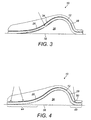
- This first concave portion 34 is resiliently flexible and flexes slightly into the passageway 36 when the weight of a user's head is applied thereto (see Fig. 3 ).
- a second concave portion 50 is provided in the rearwardly facing portion 28.
- the spine member 12 curves upwardly from the front and rear ends 18, 20, towards the passageway 36 forming the respective first and second concave portions 34, 50, in the upper surface 14.
- the radius of curvature of the first concave portion 34 is seen to be greater than the radius of curvature of the second concave portion 50.
- the front and rear portions 44, 48, of the spine member 12 curve upwardly from the resting surface 38 and flex under the weight of a user's head so as to be in contact with, or in the same plane as, the resting surface 28.
- the spine member 12 has a width from one side edge 22 to the other side edge 24 of 432 mm and a thickness of 4 mm.
- the length of the head rest 10 from the front edge to the rear edge is 480 mm, or in an alternative embodiment is 530 mm.
- a passageway 36 extends from one side edge 22 of the head rest 10 to the other side edge 24 and is of a height and width sufficient to comfortably accommodate two arms of a user side by side without impinging upon the circulation of either arm.
- the passageway 36 extends to a height of 105 mm above the resting surface 38.
- the length of the passageway 36 corresponds to the width of the head rest 10 and is 432 mm.
- the width of the passageway 36 is 412 mm, which reduces to about 232 mm when a user's head is applied to the head rest 10 due to the downward flexing of the curved portions of the front and rear ends 44, 48 (see Fig. 4 ).
- the reduced width passageway 36 remains sufficiently dimensioned to accommodate one or both arms of a user.
- a first layer of foam material 40 covers the upper surface 14 of the spine member 12 and a second layer of foam material 42 covers the lower surface 16 of the spine member 12 to form a three layer construction.
- the first foam layer 40 has a lower density than the second foam layer 42 to provide a cushion feel on the upper surface 14 and a firmer more robust feel on the lower surface 16.
- the foam material 40 provided on the upper surface 14 of the spine member 12 is of a thickness of 58 mm at its thickest point in the head support or concave portion 34 and it tapers to a thickness of 13 mm at its thinnest points.
- the thickness of the foam material on the lower surface 16 of the spine member 12 is 13 mm.
- the foam layer 40 should be non-irritating to the human user and may be of varying firmness and resiliency to suit a particular user's taste.
- polymeric foam may be used to cover the spine member 12, including by way of example but without limitation, polyurethane foam, synthetic so-called foam rubber, latex foam, or visco-elastic foam commonly referred to as "memory" foam.
- the oval shape marked "A” represents a user's head rested on the head rest 10 in a laterally side-facing disposition
- the oval shape marked "B” represents a user's forearm received through the passageway 36.
- the head rest 10 is shaped so that the user's arm B may be positioned in the passageway 36 either tucked in close to the user's head A or away from the user's head A. Either way, the user's head is elevated relative to the user's arms but is not positioned directly above the user's arm.
- the unique curved shape of the spine member 12 therefore provides distinct portions for head support and place for arms.
- the areas of the head rest marked with dashed lines are configured to flex under the weight of the user's head.
- the shape and material of the spine member 12 ensure that a load applied to the head rest in use is distributed over a relatively large area to provide even stress distribution.
- the unique shape of the spine member 12 achieves multiple functions.
- the spine member 12 allows the head of a user to be resting in an elevated position above the user's arms whilst providing a space for the user to place their arms away from the head; it provides structural integrity for a head support system, it separates two different densities of foam, the upper foam layer for comfort and the lower foam layer for durability; it allows slight flexing under the weight of the user's head for comfort and for even stress distribution; and ensures that the area of contact with the resting surface 38, which is most probably a mattress with a cover sheet, is large and flat, thereby reducing wear both on the mattress and the head rest itself.
- the head rest 10 provides support to a user's head and protection of a user's arm while allowing the neck to be relaxed.
- a user's head A may be rested on the head rest 10 in a laterally side-facing disposition while the user's arm B is received through the inner passageway 36 of the, or an adjacent, head rest 10.
- a user may lie on his or her front with his head rested on the head rest 10 in a laterally side-facing disposition and his arms received through opposite open ends of the passageway 36.
- the shape of the head rest according to the present invention encourages users to centre their heads on the forwardly facing portion 26 of the head rest 10 because the concave contour 34 of this portion of the head rest 10 makes them aware of when their heads are not centred on the head rest 10. This results in the correct positioning of head so that the head and neck are in a proper alignment position.
- the head rest can be manufactured in a range of sizes to accommodate children, adolescents, and adults of varying sizes.
- the passageway may be made larger for certain individuals, for example patients that have a broken arm in a cast, or body-builders with a greater degree of musculature around the arms.
- the actual shape and size of the passageway are not critical provided that it can comfortably accommodate one or two human arms of a user.
Description
- The present invention relates to devices on which to rest a person's head, such as a pillow. More particularly, the present invention relates to a head rest which protects a user's arm when placed under the head rest and allows the user to sleep or rest with an arm underneath his or her head without disrupting the circulation of blood through the arm.
- There are currently in use various devices on which a person may rest their head when sleeping or otherwise relaxing. The most common of these is the traditional pillow which consists of a suitable padding or filling enclosed within a textile case. When sleeping or resting on one's front or side, it is generally more comfortable to position one or both arms underneath the head or pillow. However, a problem with this position is loss of blood circulation in the arms due to the weight of the head, resulting in paresthesia, which in turn interrupts sleep.
- Although there are various known pillows designed to address the aforementioned loss of circulation in the arm during sleep or other activities, such pillows are often oddly shaped and do not allow a user to sleep comfortably.
- One object of the present invention is to provide an improved head rest of the type which allows an arm to be placed under a user's resting head such that the head does not require the arm to support the weight of the head.
-
US2003135927 A1 discloses a head rest according to the preamble ofclaim 1. - The present invention accordingly provides a head rest comprising a spine member having an upper surface, a lower surface, and front and rear ends, the upper surface comprising a generally forwardly facing portion and a generally rearwardly facing portion, wherein the generally forwardly facing portion includes a first concave portion for receiving the head of a user, the front and rear ends are configured for direct or indirect contact with a resting surface and, between the front and rear ends, the lower surface defines a passageway dimensioned to receive at least one arm of the user, wherein the spine member has sufficient rigidity such that when the user's head is resting on the member, the user's arm may be positioned in the passageway in a manner that does not require the arm to support the weight of the head characterized in that the front end of the spine member gently curves upwardly towards the passageway, the rear end of the spine member also curves upwardly towards the passageway but at a greater angle than the front end.
- The head rest according to the present invention allows a user to sleep or rest on his or her front or side having one or both arms in a natural position under the head rest without interruption from pressure on, or loss of circulation in, the user's arms.
- The head rest according to the present invention is particularly suitable for individuals pre-disposed to snoring as it allows a user to sleep comfortably on his or her front or side while maintaining the head and neck in a proper alignment position such that snoring is prevented or at least reduced. Therefore, the quality of sleep and health of the user is improved.
- In a preferred embodiment of the head rest according to the present invention, the front end of the spine member extends forwardly in the same plane as the resting surface. Preferably also, the rear end of the spine member extends rearwardly in the same plane as the resting surface.
- In one embodiment of the head rest according to the present invention, a second concave portion is provided in the generally rearwardly facing portion of the head rest. Preferably, the radius of curvature of the first concave portion in the generally forwardly facing portion is greater than the radius of curvature of the second concave portion in the generally rearwardly facing portion of the head rest. Preferably, the first and/or second concave portion is resiliently flexible and configured to flex when a user's head is applied to the forwardly facing portion of the head rest.
- The front end of the spine member gently curves upwardly towards the passageway. The initial angle of inclination of the spine member from the front end towards the passageway is up to about 30 degrees, preferably from about 5 degrees to about 20 degrees to the horizontal. The rear end of the spine member also curves upwardly towards the passageway but preferably at a greater angle than the front end. The initial angle of inclination of the spine member from the rear end towards the passageway is up to about 40 degrees, preferably from about 10 degrees to about 30 degrees to the horizontal. These curved portions of the spine member are resiliently flexible and configured to flex downwardly when a user's head is resting on the spine member.
- When a user's head is applied to the head rest, the initial upwardly inclined portions of the front and/or rear ends of the spine member flex downwardly to contact, or lie in the same plane as the resting surface. In addition to providing improved comfort and stability, this feature ensures that the load on the resting surface is distributed over a relatively large area, limiting wear and tear of the resting surface.
- In a preferred embodiment of the head rest according to the present invention, the spine member is configured such that a user's head resting on the first concave portion in the forwardly facing portion is not directly above the user's arm in the passageway. Thus, the centre of mass of the user's head and the centre of mass of the user's forearm may lie in different vertical planes, with the user's arm being closer to the rear end of the head rest and the user's head being closer to the front end of the head rest.
- The passageway is preferably dimensioned to allow a certain degree of freedom of movement of an arm within it. Ideally, the passageway is dimensioned to accommodate two arms simultaneously.
- The spine member may be made from any suitable material that is relatively rigid yet resilient. Preferably, the spine member is made from a single piece of material. More preferably, the spine member is made from moulded plastic.
- The thickness of the spine member material will, of course, vary depending upon the material used. Preferably, the spine member material has a thickness of up to about 50 mm, more preferably from about 2 mm to about 40 mm, even more preferably from about 10 mm to about 20 mm.
- The head rest according to the present invention may further comprise a cover of a cushioning material over the spine member. The cushioning material is preferably a foam material such as urethane foam having a compression density that is sufficient to cushion the head of an individual utilizing the head rest.
- The cushioning, e.g., foam, material covers at least the forwardly facing upper surface of the spine member material. In a preferred embodiment, the entire upper surface of the spine member material is covered with the cushioning material. The cushioning material is suitably thicker on the forwardly facing upper surface of the head rest, especially on the first concave portion, than elsewhere. The lower surface of the spine member may also be covered with a suitable material. The foam material covering the upper surface of the spine material preferably has a thickness of from about 20 mm to about 90 mm in the region where the head is applied and of from about 1 mm to less than about 20 mm elsewhere.
- In a preferred embodiment, both upper and lower surfaces of the spine member are covered with foam material. Suitably, the foam material on the upper surface is of a relatively lower density than the foam material on the lower surface to provide a more cushioning surface. The foam material is secured to the spine member by any convenient means, generally by glueing.
- The head rest may further comprise a removable fabric cover that generally encloses the head rest. The head rest is preferably of a design which accommodates a standard pillow case. Alternatively, the cover is adapted to be fitted to the head rest.
- The head rest according to the present invention preferably has a width and length similar to that of a standard pillow. Preferably, the head rest has a length, from the front edge to the rear edge, of from about 350 mm to about 800 mm, more preferably of between about 420 mm and about 700 mm, even more preferably of between about 460 mm and about 550 mm, and has a width of from about 350 mm to about 800 mm, more preferably of between about 400 mm and about 650 mm, even more preferably of between about 420 mm and about 500 mm.
- The upper surface of the spine member extends to a height above the resting surface that is preferably from about 80mm to about 200mm, more preferably from about 90mm to about 150mm. The height of the passageway is at least 80 mm, preferably up to about 190mm, more preferably from about 100 to about 140mm, above the resting surface. The length of the passageway extends from one side edge to the other side edge of the head rest and therefore corresponds to the width of the head rest. The width of the passageway itself is preferably at least sufficient to accommodate two arms of a user side by side.
- The head rest of the present invention allows a user to sleep or rest on his or her front or side having one or both arms in position under the head rest while reducing pressure and loss of circulation to the user's arms. By allowing the user to sleep comfortably on his or her front or side, snoring can be prevented or at least reduced.
- Further, the head rest according to the present invention allows a user to adjust the position of his or her arm or arms below the user's resting head without the user having to adjust the position of his or her resting head.
- Additionally, the head rest according to the present invention maintains the head and neck of a user in a proper alignment position when the user is sleeping or resting on his or her side and opens airways of the user in a stable manner to promote easy breathing while preventing snoring.
- The invention will now be described by way of example with reference to the accompanying drawings, in which:
-
Figure 1 illustrates a perspective view of an arm protector head rest according to the present invention; -
Figure 2 illustrates a side view of the head rest ofFigure 1 showing the positions of a user's head A and arm B; and -
Figures 3 and 4 illustrate side views of the head rest ofFigure 1 showing the forces applied in use and the areas that are resiliently flexible. - As used herein, the term 'arm' is intended to include at least the hand and/or forearm.
- As used herein, the term 'about' is interpreted to mean plus or minus 20%, more preferably plus or minus 10%, even more preferably plus or minus 5%.
- With reference to the Figures, which show one specific embodiment of the arm protector head rest according to the invention, a head rest in its totality is indicated by the
reference numeral 10. Thehead rest 10 comprises aspine member 12 formed from a single piece of sheet material having generally parallel side edges 22, 24, a front edge in the form of a semicircle and a generally straightrear edge 46 withcurved ends spine member 12 include semi-rigid or rigid, flexible plastics, such as acrylic polymer, metals, rubber, etc. Thespine member 12 has a generally curved shape in cross section and has anupper surface 14, alower surface 16, front and rear ends, 18, 20, and generally parallel side edges 22, 24. Theupper surface 14 of thespine member 12 has a forwardly facingportion 26 and a rearwardly facingportion 28 that meet at the apex 30 of aconvex portion 32. Theupper surface 14 of thespine member 12 is formed with a slightly firstconcave portion 34 in the generally forwardly facingportion 26 presenting a head support portion. This firstconcave portion 34 is resiliently flexible and flexes slightly into thepassageway 36 when the weight of a user's head is applied thereto (seeFig. 3 ). A secondconcave portion 50 is provided in therearwardly facing portion 28. Thus, thespine member 12 curves upwardly from the front andrear ends passageway 36 forming the respective first and secondconcave portions upper surface 14. The radius of curvature of the firstconcave portion 34 is seen to be greater than the radius of curvature of the secondconcave portion 50. The front andrear portions spine member 12 curve upwardly from the restingsurface 38 and flex under the weight of a user's head so as to be in contact with, or in the same plane as, the restingsurface 28. - In the embodiment illustrated in the Figures, the
spine member 12 has a width from oneside edge 22 to theother side edge 24 of 432 mm and a thickness of 4 mm. - The length of the
head rest 10 from the front edge to the rear edge is 480 mm, or in an alternative embodiment is 530 mm. - A
passageway 36 extends from oneside edge 22 of thehead rest 10 to theother side edge 24 and is of a height and width sufficient to comfortably accommodate two arms of a user side by side without impinging upon the circulation of either arm. In the embodiment illustrated in the Figures, thepassageway 36 extends to a height of 105 mm above the restingsurface 38. The length of thepassageway 36 corresponds to the width of thehead rest 10 and is 432 mm. The width of thepassageway 36 is 412 mm, which reduces to about 232 mm when a user's head is applied to thehead rest 10 due to the downward flexing of the curved portions of the front andrear ends 44, 48 (seeFig. 4 ). The reducedwidth passageway 36 remains sufficiently dimensioned to accommodate one or both arms of a user. - A first layer of
foam material 40 covers theupper surface 14 of thespine member 12 and a second layer offoam material 42 covers thelower surface 16 of thespine member 12 to form a three layer construction. Thefirst foam layer 40 has a lower density than thesecond foam layer 42 to provide a cushion feel on theupper surface 14 and a firmer more robust feel on thelower surface 16. Thefoam material 40 provided on theupper surface 14 of thespine member 12 is of a thickness of 58 mm at its thickest point in the head support orconcave portion 34 and it tapers to a thickness of 13 mm at its thinnest points. The thickness of the foam material on thelower surface 16 of thespine member 12 is 13 mm. Thefoam layer 40 should be non-irritating to the human user and may be of varying firmness and resiliency to suit a particular user's taste. - Various known types of polymeric foam may be used to cover the
spine member 12, including by way of example but without limitation, polyurethane foam, synthetic so-called foam rubber, latex foam, or visco-elastic foam commonly referred to as "memory" foam. - In
Figure 2 , the oval shape marked "A" represents a user's head rested on thehead rest 10 in a laterally side-facing disposition, and the oval shape marked "B" represents a user's forearm received through thepassageway 36. It is clear fromFigure 2 , that thehead rest 10 is shaped so that the user's arm B may be positioned in thepassageway 36 either tucked in close to the user's head A or away from the user's head A. Either way, the user's head is elevated relative to the user's arms but is not positioned directly above the user's arm. The unique curved shape of thespine member 12 therefore provides distinct portions for head support and place for arms. - With reference to
Figures 3 and 4 , the areas of the head rest marked with dashed lines are configured to flex under the weight of the user's head. The shape and material of thespine member 12 ensure that a load applied to the head rest in use is distributed over a relatively large area to provide even stress distribution. - It is clear from
figures 2 to 4 that the unique shape of thespine member 12 achieves multiple functions. Thus, thespine member 12 allows the head of a user to be resting in an elevated position above the user's arms whilst providing a space for the user to place their arms away from the head; it provides structural integrity for a head support system, it separates two different densities of foam, the upper foam layer for comfort and the lower foam layer for durability; it allows slight flexing under the weight of the user's head for comfort and for even stress distribution; and ensures that the area of contact with the restingsurface 38, which is most probably a mattress with a cover sheet, is large and flat, thereby reducing wear both on the mattress and the head rest itself. - With reference to
Figure 2 , thehead rest 10 according to the present invention provides support to a user's head and protection of a user's arm while allowing the neck to be relaxed. A user's head A may be rested on thehead rest 10 in a laterally side-facing disposition while the user's arm B is received through theinner passageway 36 of the, or an adjacent,head rest 10. Alternatively, a user may lie on his or her front with his head rested on thehead rest 10 in a laterally side-facing disposition and his arms received through opposite open ends of thepassageway 36. - Furthermore, the shape of the head rest according to the present invention encourages users to centre their heads on the forwardly facing
portion 26 of thehead rest 10 because theconcave contour 34 of this portion of thehead rest 10 makes them aware of when their heads are not centred on thehead rest 10. This results in the correct positioning of head so that the head and neck are in a proper alignment position. - The foregoing description of a specific embodiment of the present invention has been presented for the purpose of illustration and description. It is not intended to be exhaustive or limit the present invention to the precise form disclosed, and variations and modifications are possible in the light of the above teaching. Therefore, the present invention includes all variations and modifications encompassed within the scope of the appended claims.
- In this regard, it will be apparent to one skilled in this art that the head rest can be manufactured in a range of sizes to accommodate children, adolescents, and adults of varying sizes.
- Further, it should be recognised that the passageway may be made larger for certain individuals, for example patients that have a broken arm in a cast, or body-builders with a greater degree of musculature around the arms. Thus, the actual shape and size of the passageway are not critical provided that it can comfortably accommodate one or two human arms of a user.
Claims (14)
- A head rest (10) comprising a spine member (12) having an upper surface (14), a lower surface (16), and front and rear ends (18, 20), the upper surface (14) comprising a generally forwardly facing portion (26) and a generally rearwardly facing portion (28), wherein the generally forwardly facing portion (26) includes a first concave portion (34) for receiving the head of a user, the front and rear ends (18, 20) are configured for contact with a resting surface (38) and, between the front and rear ends (18, 20), the lower surface (16) defines a passageway (36) dimensioned to receive at least one arm of the user, wherein the spine member (12) has sufficient rigidity such that when the user's head is resting on the spine member (12), the user's arm may be positioned in the passageway (36) in a manner that does not require the arm to support the weight of the head, characterized in that the front end (18) of the spine member (12) gently curves upwardly towards the passageway (36), the rear end (20) of the spine member (12) also curves upwardly towards the passageway (36) but at a greater angle than the front end (18).
- A head rest (10) according to claim 1, wherein the front end (18) of the spine member (12) extends in the same plane as the resting surface (38).
- A head rest (10) according to claim 1 or claim 2, wherein a second concave portion (50) is provided in the generally rearwardly facing portion (28).
- A head rest (10) according to claim 3, wherein the radius of curvature of the first concave portion (34) is greater than the radius of curvature of the second concave portion (50).
- A head rest (10) according to any one of the preceding claims, wherein the first concave portion (34) is resiliently flexible and configured to flex when a user's head is applied thereto.
- A head rest (10) according to any one of claims 3 to 5, wherein the second concave portion (50) is resiliently flexible and configured to flex when a user's head is applied to the first concave portion (34).
- A head rest (10) according to any one of the preceding claims, wherein the rear end (20) extends in the same plane as the resting surface (38).
- A head rest (10) according to any one of the preceding claims, wherein the passageway (36) is dimensioned to accommodate two arms simultaneously.
- A head rest (10) according to any one of the preceding claims, wherein the spine member (12) is made from moulded plastic.
- A head rest (10) according to any one of the preceding claims, wherein at least the forwardly facing upper surface (26) is covered with a foam material (40).
- A head rest (10) according to any one of the preceding claims, wherein the foam material (40) covers the entire upper surface (14) of the spine member (12) and is relatively thicker in the first concave portion (34) than elsewhere.
- A head rest (10) according to any one of the preceding claims, wherein the lower surface (16) of the spine member (12) is covered with a foam material (42).
- A head rest (10) according to claim 12, wherein the foam material (40, 42) on the upper and lower surfaces (14, 16) have different densities.
- A head rest (10) according to any one of the preceding claims, further comprising a fabric removable cover.
Applications Claiming Priority (2)
| Application Number | Priority Date | Filing Date | Title |
|---|---|---|---|
| GBGB1113055.6A GB201113055D0 (en) | 2011-07-29 | 2011-07-29 | Arm protector head rest |
| PCT/GB2012/000621 WO2013017817A1 (en) | 2011-07-29 | 2012-07-27 | Arm protector head rest |
Publications (2)
| Publication Number | Publication Date |
|---|---|
| EP2736385A1 EP2736385A1 (en) | 2014-06-04 |
| EP2736385B1 true EP2736385B1 (en) | 2016-09-14 |
Family
ID=44676378
Family Applications (1)
| Application Number | Title | Priority Date | Filing Date |
|---|---|---|---|
| EP12754041.7A Active EP2736385B1 (en) | 2011-07-29 | 2012-07-27 | Arm protector head rest |
Country Status (7)
| Country | Link |
|---|---|
| US (1) | US8997285B2 (en) |
| EP (1) | EP2736385B1 (en) |
| CA (1) | CA2843250C (en) |
| ES (1) | ES2606153T3 (en) |
| GB (1) | GB201113055D0 (en) |
| PL (1) | PL2736385T3 (en) |
| WO (1) | WO2013017817A1 (en) |
Families Citing this family (13)
| Publication number | Priority date | Publication date | Assignee | Title |
|---|---|---|---|---|
| CA162764S (en) * | 2014-12-15 | 2016-02-26 | Philip Moore | Pillow |
| GB2535229B (en) * | 2015-02-13 | 2017-11-29 | Jensen Gemma | Neck support pillow |
| USD789709S1 (en) * | 2015-06-02 | 2017-06-20 | Jianhan Zou | Massage pillow |
| USD809321S1 (en) * | 2015-12-11 | 2018-02-06 | JAB Distributors, LLC | Pillow |
| CN105852552A (en) * | 2016-06-21 | 2016-08-17 | 苏舒 | Pillow with regulating bars |
| US20180153321A1 (en) * | 2017-07-17 | 2018-06-07 | Bentley Dawson Oliver | Pillow |
| US10791845B2 (en) * | 2018-01-02 | 2020-10-06 | Gary TACON | Therapeutic cushion |
| US10888183B2 (en) | 2018-11-20 | 2021-01-12 | Popitz, LLC | Method, system, and apparatus for facilitating positioning a person in supine sniff position |
| USD948410S1 (en) * | 2018-12-27 | 2022-04-12 | Sichuan Golden Ridge Intelligence Science & Technology Co., Ltd. | Operating platform |
| US11290491B2 (en) * | 2019-03-14 | 2022-03-29 | Oracle International Corporation | Methods, systems, and computer readable media for utilizing a security service engine to assess security vulnerabilities on a security gateway element |
| USD864612S1 (en) | 2019-06-28 | 2019-10-29 | James Phillip Castellano | Foot pillow |
| US20220030965A1 (en) * | 2020-07-31 | 2022-02-03 | Charles Kidd | Protective Arm Cover |
| CN220756996U (en) * | 2023-08-10 | 2024-04-12 | 普勒森(香港)科技有限公司 | Pillow |
Family Cites Families (18)
| Publication number | Priority date | Publication date | Assignee | Title |
|---|---|---|---|---|
| US3883906A (en) * | 1974-02-28 | 1975-05-20 | Alray Sumpter | Sleeping pillow with arm openings |
| US4821355A (en) * | 1987-11-19 | 1989-04-18 | Burkhardt George J | Self-adjusting orthopedic cervical pillow |
| DE9300619U1 (en) * | 1992-02-07 | 1993-03-11 | Seeburger, Franz-Josef, 8232 Bayerisch Gmain, De | |
| US5579551A (en) * | 1995-09-11 | 1996-12-03 | Tommaney; Joseph V. | Arch shaped pillow apparatus with ear accomodating hole |
| US5644809A (en) * | 1996-05-15 | 1997-07-08 | Olson; Michael J. | Cervical pillow |
| SE9602764L (en) * | 1996-07-12 | 1997-10-06 | Jb Prominens Ab | Pillow |
| USD407256S (en) * | 1996-07-12 | 1999-03-30 | Jb Prominens Ab | Pillow |
| US6336236B1 (en) * | 1999-11-22 | 2002-01-08 | Steve Dalton | Snuggle pillow |
| US6691353B2 (en) * | 2001-07-20 | 2004-02-17 | Richard Apollo Fuhriman | Arm pillow |
| US6640367B2 (en) * | 2002-01-23 | 2003-11-04 | Chih-Yu Hsia | Pillows |
| USD471050S1 (en) * | 2002-08-01 | 2003-03-04 | Haubner Tammie W | Arm tunnel pillow |
| USD484727S1 (en) * | 2002-10-11 | 2004-01-06 | Marsha Haywood | Pillow |
| US6671907B1 (en) * | 2003-04-15 | 2004-01-06 | Najeeb Zuberi | Sleep apnea avoidance process and apparatus |
| US7228580B2 (en) * | 2005-01-14 | 2007-06-12 | Steven G. Dalton | Universal pillow |
| US7216387B2 (en) * | 2005-06-16 | 2007-05-15 | Scott Laxton | Arched pillow assembly |
| US7441293B1 (en) * | 2007-09-10 | 2008-10-28 | Singer Starr Stacker, Llc | Support for a lower shoulder and extended arms of a person lying on their side |
| US8069515B1 (en) * | 2010-06-07 | 2011-12-06 | Craig Tingey | Orthopedic pillow with shoulder recess |
| US8806684B1 (en) * | 2013-09-06 | 2014-08-19 | Sandra E. Ortega | Pillow device |
-
2011
- 2011-07-29 GB GBGB1113055.6A patent/GB201113055D0/en not_active Ceased
-
2012
- 2012-07-27 CA CA2843250A patent/CA2843250C/en active Active
- 2012-07-27 ES ES12754041.7T patent/ES2606153T3/en active Active
- 2012-07-27 EP EP12754041.7A patent/EP2736385B1/en active Active
- 2012-07-27 PL PL12754041T patent/PL2736385T3/en unknown
- 2012-07-27 WO PCT/GB2012/000621 patent/WO2013017817A1/en active Application Filing
- 2012-07-27 US US14/235,913 patent/US8997285B2/en active Active
Also Published As
| Publication number | Publication date |
|---|---|
| WO2013017817A1 (en) | 2013-02-07 |
| PL2736385T3 (en) | 2017-03-31 |
| EP2736385A1 (en) | 2014-06-04 |
| ES2606153T3 (en) | 2017-03-23 |
| CA2843250C (en) | 2018-04-03 |
| US20150040321A1 (en) | 2015-02-12 |
| CA2843250A1 (en) | 2013-02-07 |
| GB201113055D0 (en) | 2011-09-14 |
| US8997285B2 (en) | 2015-04-07 |
Similar Documents
| Publication | Publication Date | Title |
|---|---|---|
| EP2736385B1 (en) | Arm protector head rest | |
| EP1898749B1 (en) | A support for supporting the neck and head of a human being | |
| KR101996180B1 (en) | Pillow possible control level | |
| US20110131728A1 (en) | Ergonomic pillow | |
| US20130318722A1 (en) | Functional Pillow | |
| JP2020525241A (en) | pillow | |
| KR101577903B1 (en) | pillow for effect of correction and treatment | |
| US20140075677A1 (en) | Neck support pillow | |
| KR100978285B1 (en) | Sound sleep pillow | |
| KR102109986B1 (en) | Faculty pillow | |
| KR101513962B1 (en) | Functional pillow | |
| KR100982116B1 (en) | Functional head rest pillow for support of head and protection of cervical vertebra | |
| KR101626126B1 (en) | a functional pillow | |
| KR20170074496A (en) | Functional Pillow | |
| KR101768611B1 (en) | Pillow | |
| WO2009038278A1 (en) | A pillow with multi-layered structure | |
| CN208017302U (en) | A kind of anti-skid device of neckpillow | |
| US7594289B1 (en) | Pillow | |
| KR20200073815A (en) | Combined pillow to be helpful to cure straight neck | |
| CN218074371U (en) | Subregion adjustable children are with cloud shape hose pillow | |
| CN218044435U (en) | Afternoon nap pillow | |
| KR200491545Y1 (en) | Custom type functional pillow | |
| KR102153462B1 (en) | Height adjustment C-curve pillow with towel | |
| KR20100133337A (en) | Equipped with height-adjustable pillow core | |
| KR102088842B1 (en) | Multi-functional waist pillow |
Legal Events
| Date | Code | Title | Description |
|---|---|---|---|
| PUAI | Public reference made under article 153(3) epc to a published international application that has entered the european phase |
Free format text: ORIGINAL CODE: 0009012 |
|
| 17P | Request for examination filed |
Effective date: 20140207 |
|
| AK | Designated contracting states |
Kind code of ref document: A1 Designated state(s): AL AT BE BG CH CY CZ DE DK EE ES FI FR GB GR HR HU IE IS IT LI LT LU LV MC MK MT NL NO PL PT RO RS SE SI SK SM TR |
|
| RIN1 | Information on inventor provided before grant (corrected) |
Inventor name: MOORE, PHILIP |
|
| DAX | Request for extension of the european patent (deleted) | ||
| RAP1 | Party data changed (applicant data changed or rights of an application transferred) |
Owner name: MOORE, PHILIP Owner name: MOORE, JAMES |
|
| RIN1 | Information on inventor provided before grant (corrected) |
Inventor name: MOORE, JAMES Inventor name: MOORE, PHILIP |
|
| GRAP | Despatch of communication of intention to grant a patent |
Free format text: ORIGINAL CODE: EPIDOSNIGR1 |
|
| INTG | Intention to grant announced |
Effective date: 20160401 |
|
| GRAS | Grant fee paid |
Free format text: ORIGINAL CODE: EPIDOSNIGR3 |
|
| GRAA | (expected) grant |
Free format text: ORIGINAL CODE: 0009210 |
|
| AK | Designated contracting states |
Kind code of ref document: B1 Designated state(s): AL AT BE BG CH CY CZ DE DK EE ES FI FR GB GR HR HU IE IS IT LI LT LU LV MC MK MT NL NO PL PT RO RS SE SI SK SM TR |
|
| REG | Reference to a national code |
Ref country code: GB Ref legal event code: FG4D |
|
| REG | Reference to a national code |
Ref country code: CH Ref legal event code: EP |
|
| REG | Reference to a national code |
Ref country code: IE Ref legal event code: FG4D |
|
| REG | Reference to a national code |
Ref country code: AT Ref legal event code: REF Ref document number: 827947 Country of ref document: AT Kind code of ref document: T Effective date: 20161015 |
|
| REG | Reference to a national code |
Ref country code: DE Ref legal event code: R096 Ref document number: 602012022918 Country of ref document: DE |
|
| REG | Reference to a national code |
Ref country code: NL Ref legal event code: FP |
|
| REG | Reference to a national code |
Ref country code: LT Ref legal event code: MG4D |
|
| PG25 | Lapsed in a contracting state [announced via postgrant information from national office to epo] |
Ref country code: HR Free format text: LAPSE BECAUSE OF FAILURE TO SUBMIT A TRANSLATION OF THE DESCRIPTION OR TO PAY THE FEE WITHIN THE PRESCRIBED TIME-LIMIT Effective date: 20160914 Ref country code: RS Free format text: LAPSE BECAUSE OF FAILURE TO SUBMIT A TRANSLATION OF THE DESCRIPTION OR TO PAY THE FEE WITHIN THE PRESCRIBED TIME-LIMIT Effective date: 20160914 Ref country code: NO Free format text: LAPSE BECAUSE OF FAILURE TO SUBMIT A TRANSLATION OF THE DESCRIPTION OR TO PAY THE FEE WITHIN THE PRESCRIBED TIME-LIMIT Effective date: 20161214 Ref country code: FI Free format text: LAPSE BECAUSE OF FAILURE TO SUBMIT A TRANSLATION OF THE DESCRIPTION OR TO PAY THE FEE WITHIN THE PRESCRIBED TIME-LIMIT Effective date: 20160914 Ref country code: LT Free format text: LAPSE BECAUSE OF FAILURE TO SUBMIT A TRANSLATION OF THE DESCRIPTION OR TO PAY THE FEE WITHIN THE PRESCRIBED TIME-LIMIT Effective date: 20160914 |
|
| REG | Reference to a national code |
Ref country code: AT Ref legal event code: MK05 Ref document number: 827947 Country of ref document: AT Kind code of ref document: T Effective date: 20160914 |
|
| PG25 | Lapsed in a contracting state [announced via postgrant information from national office to epo] |
Ref country code: LV Free format text: LAPSE BECAUSE OF FAILURE TO SUBMIT A TRANSLATION OF THE DESCRIPTION OR TO PAY THE FEE WITHIN THE PRESCRIBED TIME-LIMIT Effective date: 20160914 Ref country code: SE Free format text: LAPSE BECAUSE OF FAILURE TO SUBMIT A TRANSLATION OF THE DESCRIPTION OR TO PAY THE FEE WITHIN THE PRESCRIBED TIME-LIMIT Effective date: 20160914 |
|
| PG25 | Lapsed in a contracting state [announced via postgrant information from national office to epo] |
Ref country code: EE Free format text: LAPSE BECAUSE OF FAILURE TO SUBMIT A TRANSLATION OF THE DESCRIPTION OR TO PAY THE FEE WITHIN THE PRESCRIBED TIME-LIMIT Effective date: 20160914 Ref country code: RO Free format text: LAPSE BECAUSE OF FAILURE TO SUBMIT A TRANSLATION OF THE DESCRIPTION OR TO PAY THE FEE WITHIN THE PRESCRIBED TIME-LIMIT Effective date: 20160914 |
|
| PG25 | Lapsed in a contracting state [announced via postgrant information from national office to epo] |
Ref country code: SK Free format text: LAPSE BECAUSE OF FAILURE TO SUBMIT A TRANSLATION OF THE DESCRIPTION OR TO PAY THE FEE WITHIN THE PRESCRIBED TIME-LIMIT Effective date: 20160914 Ref country code: PT Free format text: LAPSE BECAUSE OF FAILURE TO SUBMIT A TRANSLATION OF THE DESCRIPTION OR TO PAY THE FEE WITHIN THE PRESCRIBED TIME-LIMIT Effective date: 20170116 Ref country code: BG Free format text: LAPSE BECAUSE OF FAILURE TO SUBMIT A TRANSLATION OF THE DESCRIPTION OR TO PAY THE FEE WITHIN THE PRESCRIBED TIME-LIMIT Effective date: 20161214 Ref country code: SM Free format text: LAPSE BECAUSE OF FAILURE TO SUBMIT A TRANSLATION OF THE DESCRIPTION OR TO PAY THE FEE WITHIN THE PRESCRIBED TIME-LIMIT Effective date: 20160914 Ref country code: IS Free format text: LAPSE BECAUSE OF FAILURE TO SUBMIT A TRANSLATION OF THE DESCRIPTION OR TO PAY THE FEE WITHIN THE PRESCRIBED TIME-LIMIT Effective date: 20170114 Ref country code: AT Free format text: LAPSE BECAUSE OF FAILURE TO SUBMIT A TRANSLATION OF THE DESCRIPTION OR TO PAY THE FEE WITHIN THE PRESCRIBED TIME-LIMIT Effective date: 20160914 |
|
| REG | Reference to a national code |
Ref country code: DE Ref legal event code: R097 Ref document number: 602012022918 Country of ref document: DE |
|
| REG | Reference to a national code |
Ref country code: GR Ref legal event code: EP Ref document number: 20160403079 Country of ref document: GR Effective date: 20170410 |
|
| PLBE | No opposition filed within time limit |
Free format text: ORIGINAL CODE: 0009261 |
|
| STAA | Information on the status of an ep patent application or granted ep patent |
Free format text: STATUS: NO OPPOSITION FILED WITHIN TIME LIMIT |
|
| REG | Reference to a national code |
Ref country code: FR Ref legal event code: PLFP Year of fee payment: 6 |
|
| PG25 | Lapsed in a contracting state [announced via postgrant information from national office to epo] |
Ref country code: DK Free format text: LAPSE BECAUSE OF FAILURE TO SUBMIT A TRANSLATION OF THE DESCRIPTION OR TO PAY THE FEE WITHIN THE PRESCRIBED TIME-LIMIT Effective date: 20160914 |
|
| 26N | No opposition filed |
Effective date: 20170615 |
|
| PG25 | Lapsed in a contracting state [announced via postgrant information from national office to epo] |
Ref country code: SI Free format text: LAPSE BECAUSE OF FAILURE TO SUBMIT A TRANSLATION OF THE DESCRIPTION OR TO PAY THE FEE WITHIN THE PRESCRIBED TIME-LIMIT Effective date: 20160914 |
|
| REG | Reference to a national code |
Ref country code: FR Ref legal event code: PLFP Year of fee payment: 7 |
|
| PGFP | Annual fee paid to national office [announced via postgrant information from national office to epo] |
Ref country code: LU Payment date: 20180718 Year of fee payment: 7 |
|
| PGFP | Annual fee paid to national office [announced via postgrant information from national office to epo] |
Ref country code: MT Payment date: 20180723 Year of fee payment: 7 |
|
| PG25 | Lapsed in a contracting state [announced via postgrant information from national office to epo] |
Ref country code: AL Free format text: LAPSE BECAUSE OF FAILURE TO SUBMIT A TRANSLATION OF THE DESCRIPTION OR TO PAY THE FEE WITHIN THE PRESCRIBED TIME-LIMIT Effective date: 20160914 |
|
| PGFP | Annual fee paid to national office [announced via postgrant information from national office to epo] |
Ref country code: TR Payment date: 20180903 Year of fee payment: 9 Ref country code: CH Payment date: 20180719 Year of fee payment: 7 |
|
| PG25 | Lapsed in a contracting state [announced via postgrant information from national office to epo] |
Ref country code: HU Free format text: LAPSE BECAUSE OF FAILURE TO SUBMIT A TRANSLATION OF THE DESCRIPTION OR TO PAY THE FEE WITHIN THE PRESCRIBED TIME-LIMIT; INVALID AB INITIO Effective date: 20120727 Ref country code: MC Free format text: LAPSE BECAUSE OF FAILURE TO SUBMIT A TRANSLATION OF THE DESCRIPTION OR TO PAY THE FEE WITHIN THE PRESCRIBED TIME-LIMIT Effective date: 20160914 |
|
| PG25 | Lapsed in a contracting state [announced via postgrant information from national office to epo] |
Ref country code: CY Free format text: LAPSE BECAUSE OF NON-PAYMENT OF DUE FEES Effective date: 20160914 |
|
| PG25 | Lapsed in a contracting state [announced via postgrant information from national office to epo] |
Ref country code: MK Free format text: LAPSE BECAUSE OF FAILURE TO SUBMIT A TRANSLATION OF THE DESCRIPTION OR TO PAY THE FEE WITHIN THE PRESCRIBED TIME-LIMIT Effective date: 20160914 |
|
| REG | Reference to a national code |
Ref country code: DE Ref legal event code: R082 Ref document number: 602012022918 Country of ref document: DE Representative=s name: 2K PATENT- UND RECHTSANWAELTE PARTNERSCHAFT MB, DE |
|
| REG | Reference to a national code |
Ref country code: CH Ref legal event code: PL |
|
| PG25 | Lapsed in a contracting state [announced via postgrant information from national office to epo] |
Ref country code: TR Free format text: LAPSE BECAUSE OF FAILURE TO SUBMIT A TRANSLATION OF THE DESCRIPTION OR TO PAY THE FEE WITHIN THE PRESCRIBED TIME-LIMIT Effective date: 20160914 |
|
| REG | Reference to a national code |
Ref country code: BE Ref legal event code: MM Effective date: 20190731 |
|
| PG25 | Lapsed in a contracting state [announced via postgrant information from national office to epo] |
Ref country code: BE Free format text: LAPSE BECAUSE OF NON-PAYMENT OF DUE FEES Effective date: 20190731 Ref country code: CZ Free format text: LAPSE BECAUSE OF NON-PAYMENT OF DUE FEES Effective date: 20190727 Ref country code: LU Free format text: LAPSE BECAUSE OF NON-PAYMENT OF DUE FEES Effective date: 20190727 Ref country code: LI Free format text: LAPSE BECAUSE OF NON-PAYMENT OF DUE FEES Effective date: 20190731 Ref country code: CH Free format text: LAPSE BECAUSE OF NON-PAYMENT OF DUE FEES Effective date: 20190731 |
|
| PG25 | Lapsed in a contracting state [announced via postgrant information from national office to epo] |
Ref country code: MT Free format text: LAPSE BECAUSE OF FAILURE TO SUBMIT A TRANSLATION OF THE DESCRIPTION OR TO PAY THE FEE WITHIN THE PRESCRIBED TIME-LIMIT Effective date: 20190727 |
|
| PGFP | Annual fee paid to national office [announced via postgrant information from national office to epo] |
Ref country code: NL Payment date: 20220720 Year of fee payment: 11 |
|
| PGFP | Annual fee paid to national office [announced via postgrant information from national office to epo] |
Ref country code: IE Payment date: 20220704 Year of fee payment: 11 |
|
| PGFP | Annual fee paid to national office [announced via postgrant information from national office to epo] |
Ref country code: PL Payment date: 20220718 Year of fee payment: 11 Ref country code: GR Payment date: 20220725 Year of fee payment: 11 |
|
| P01 | Opt-out of the competence of the unified patent court (upc) registered |
Effective date: 20230505 |
|
| PGFP | Annual fee paid to national office [announced via postgrant information from national office to epo] |
Ref country code: IT Payment date: 20230719 Year of fee payment: 12 Ref country code: GB Payment date: 20230717 Year of fee payment: 12 Ref country code: ES Payment date: 20230926 Year of fee payment: 12 |
|
| PGFP | Annual fee paid to national office [announced via postgrant information from national office to epo] |
Ref country code: FR Payment date: 20230725 Year of fee payment: 12 Ref country code: DE Payment date: 20230719 Year of fee payment: 12 |
|
| REG | Reference to a national code |
Ref country code: NL Ref legal event code: MM Effective date: 20230801 |
|
| PG25 | Lapsed in a contracting state [announced via postgrant information from national office to epo] |
Ref country code: GR Free format text: LAPSE BECAUSE OF NON-PAYMENT OF DUE FEES Effective date: 20240207 |
|
| PG25 | Lapsed in a contracting state [announced via postgrant information from national office to epo] |
Ref country code: NL Free format text: LAPSE BECAUSE OF NON-PAYMENT OF DUE FEES Effective date: 20230801 |
|
| PG25 | Lapsed in a contracting state [announced via postgrant information from national office to epo] |
Ref country code: NL Free format text: LAPSE BECAUSE OF NON-PAYMENT OF DUE FEES Effective date: 20230801 Ref country code: GR Free format text: LAPSE BECAUSE OF NON-PAYMENT OF DUE FEES Effective date: 20240207 |