EP2736265A1 - Tonsignaladapter und tonsignalübertragungssystem - Google Patents
Tonsignaladapter und tonsignalübertragungssystem Download PDFInfo
- Publication number
- EP2736265A1 EP2736265A1 EP12814990.3A EP12814990A EP2736265A1 EP 2736265 A1 EP2736265 A1 EP 2736265A1 EP 12814990 A EP12814990 A EP 12814990A EP 2736265 A1 EP2736265 A1 EP 2736265A1
- Authority
- EP
- European Patent Office
- Prior art keywords
- pin
- audio signal
- audio
- output
- resistor
- Prior art date
- Legal status (The legal status is an assumption and is not a legal conclusion. Google has not performed a legal analysis and makes no representation as to the accuracy of the status listed.)
- Withdrawn
Links
Images


Classifications
-
- H—ELECTRICITY
- H04—ELECTRIC COMMUNICATION TECHNIQUE
- H04R—LOUDSPEAKERS, MICROPHONES, GRAMOPHONE PICK-UPS OR LIKE ACOUSTIC ELECTROMECHANICAL TRANSDUCERS; ELECTRIC HEARING AIDS; PUBLIC ADDRESS SYSTEMS
- H04R3/00—Circuits for transducers
-
- H—ELECTRICITY
- H04—ELECTRIC COMMUNICATION TECHNIQUE
- H04R—LOUDSPEAKERS, MICROPHONES, GRAMOPHONE PICK-UPS OR LIKE ACOUSTIC ELECTROMECHANICAL TRANSDUCERS; ELECTRIC HEARING AIDS; PUBLIC ADDRESS SYSTEMS
- H04R2420/00—Details of connection covered by H04R, not provided for in its groups
- H04R2420/09—Applications of special connectors, e.g. USB, XLR, in loudspeakers, microphones or headphones
-
- H—ELECTRICITY
- H04—ELECTRIC COMMUNICATION TECHNIQUE
- H04R—LOUDSPEAKERS, MICROPHONES, GRAMOPHONE PICK-UPS OR LIKE ACOUSTIC ELECTROMECHANICAL TRANSDUCERS; ELECTRIC HEARING AIDS; PUBLIC ADDRESS SYSTEMS
- H04R5/00—Stereophonic arrangements
- H04R5/04—Circuit arrangements, e.g. for selective connection of amplifier inputs/outputs to loudspeakers, for loudspeaker detection, or for adaptation of settings to personal preferences or hearing impairments
Definitions
- the present disclosure generally relates to an electronic technical field, and more particularly relates to an audio signal adapter device and a system for transmitting an audio signal.
- the electronic equipment may be connected with a mobile communication device (such as a mobile phone) via a loudspeaker interface (such as a headphone interface) of the mobile communication device for receiving an audio signal output from the mobile communication device, and can also receive the audio signal output from a loudspeaker of the mobile communication device or a loudspeaker of a fixed telephone device via a microphone (MIC).
- a mobile communication device such as a mobile phone
- a loudspeaker interface such as a headphone interface
- MIC microphone
- USB interface With the popularization of a USB interface, a large number of electronic equipments are provided with the USB interface. Thus, how to receive the audio signal output from the loudspeaker of the mobile communication device or the loudspeaker of the fixed telephone device via the USB interface of the electronic equipment is a technical problem which needs to be solved currently.
- the present disclosure provides an audio signal adapter device which can output an audio signal output from a loudspeaker to an electronic equipment via a USB interface and a corresponding audio signal receiving device.
- the present disclosure provides a system for transmitting an audio signal.
- the system is configured to receive the audio signal, and the system comprises an audio signal adapter device and an audio signal receiving device.
- the audio signal adapter device comprises a microphone, an amplifying unit and a USB adapter interface.
- the microphone is configured to receive the audio signal and to output the audio signal via an audio pin.
- the amplifying unit comprises an audio input pin and an audio output pin, and is configured to amplify the audio signal received via the audio input pin and to output an amplified audio signal via the audio output pin.
- the USB adapter interface is connected with the audio signal receiving device and comprises an audio signal pin.
- the audio pin of the microphone is connected with the audio input pin of the amplifying unit, and the audio output pin of the amplifying unit is connected with the audio signal pin of the USB adapter interface.
- the audio signal receiving device comprises a USB interface and an audio receiving module.
- the USB interface comprises an audio signal pin, and the audio signal pin of the USB interface is connected with the audio signal pin of the USB adapter interface.
- the audio receiving module is connected with the audio signal pin of the USB interface, and configured to receive the audio signal via the audio signal pin of the USB interface.
- the audio signal pin of the USB adapter interface is one of a D+ pin and a D- pin of the USB adapter interface, and the audio signal pin of the USB interface is one of a D+ pin and a D-pin of the USB interface.
- the microphone further comprises a ground pin
- the amplifying unit further comprises a ground pin
- each of the USB adapter interface and the USB interface further comprises a reference signal pin.
- the reference signal pin of the USB adapter interface is connected with the ground pin of the microphone and/or the ground pin of the amplifying unit.
- the reference signal pin of the USB adapter interface is the other one of the D+ pin and the D- pin of the USB adapter interface
- the reference signal pin of the USB interface is the other one of the D+ pin and the D- pin of the USB interface.
- the audio receiving module comprises a first comparator.
- a positive terminal of the first comparator is connected with the audio signal pin of the USB interface, a negative terminal of the first comparator is connected with the reference signal pin of the USB interface, and an output pin of the first comparator is configured to output a square wave corresponding to an input audio signal; or the positive terminal of the first comparator is connected with the reference signal pin of the USB interface, the negative terminal of the first comparator is connected with the audio signal pin of the USB interface, and the output pin of the first comparator is configured to output the square wave corresponding to the input audio signal.
- the audio receiving module comprises a direct current signal isolation unit, a first direct current bias unit, a second direct current bias unit and a second comparator.
- the direct current signal isolation unit has an input end connected with the audio signal pin of the USB interface and an output end connected with the second direct current bias unit, and is configured to isolate a direct current level in the audio signal received via the audio signal pin of the USB interface to obtain a processed audio signal and to output the processed audio signal via the output end of the direct current signal isolation unit.
- the second direct current bias unit has an input end connected with the direct current signal isolation unit and an output end connected with a negative terminal of the second comparator, and is configured to add a direct current bias to the audio signal input from the input end of the second direct current bias unit to obtain a biased audio signal and to output the biased audio signal via the output end of the second direct current bias unit.
- the first direct current bias unit has an output end connected with a positive terminal of the second comparator, and is configured to output a reference level.
- the second comparator is configured to output a square wave corresponding to the audio signal via an output terminal of the second comparator under an action of the reference level input from the positive terminal of the second comparator and the biased audio signal input from the negative terminal of the second comparator.
- the output terminal of the second comparator is connected with the positive terminal of the second comparator via a resistor R7 and is connected with a pull-up resistor R8.
- the first direct current bias unit comprises a resistor (R3) and a resistor (R4).
- a first terminal of the resistor (R3) is connected with a first power supply, and a second terminal of the resistor (R3) is connected with the resistor (R4).
- a first terminal of the resistor (R4) is connected with the resistor (R3) and the output end of the first direct current bias unit respectively, and a second terminal of the resistor (R4) is grounded.
- the second direct current bias unit comprises a resistor (R5) and a resistor (R6). A first terminal of the resistor (R5) is connected with a second power supply, and a second terminal of the resistor (R5) is connected with the resistor (R6).
- a first terminal of the resistor (R6) is connected with the resistor (R5) and the output end of the second direct current bias unit respectively, and a second terminal of the resistor (R6) is grounded.
- An output voltage of the first power supply is equal to the output voltage of the second power supply
- a resistance of the resistor (R3) is equal to a resistance of the resistor (R5)
- a resistance of the resistor (R4) is equal to a resistance of the resistor (R6).
- the present disclosure further provides an audio signal adapter device.
- the audio signal adapter device comprises a microphone.
- the device further comprises an amplifying unit and a USB adapter interface.
- the microphone is configured to receive an audio signal and to output the audio signal via an audio pin.
- the amplifying unit comprises an audio input pin and an audio output pin, and is configured to amplify the audio signal received via the audio input pin and to output an amplified audio signal via the audio output pin.
- the USB adapter interface is connected with an audio signal receiving device and comprises an audio signal pin.
- the audio pin of the microphone is connected with the audio input pin of the amplifying unit, and the audio output pin of the amplifying unit is connected with the audio signal pin of the USB adapter interface.
- the audio signal pin of the USB adapter interface is one of a D+ pin and a D- pin of the USB adapter interface.
- the microphone further comprises a ground pin
- the amplifying unit further comprises a ground pin
- the USB adapter interface further comprises a reference signal pin.
- the reference signal pin of the USB adapter interface is connected with the ground pin of the microphone and/or the ground pin of the amplifying unit.
- the reference signal pin of the USB adapter interface is the other one of the D+ pin and the D- pin of the USB adapter interface.
- the electronic equipment can receive the audio signal output from a loudspeaker via the USB interface with a relatively low hardware cost.
- the electronic equipment can receive the audio signal output from the loudspeaker via the USB interface, without the need of providing a separate loudspeaker interface, and without the need of providing an MIC functional module, thus reducing a cost of the electronic equipment and decreasing a size of the electronic equipment.
- the audio signal adapter device in the present disclosure may be an audio cable, an audio adapter cable, an audio adapter, etc.
- Fig. 1 is a schematic diagram of an audio signal adapter device according to the first embodiment of the present disclosure.
- the audio signal adapter device comprises a microphone (MIC), an amplifying unit (such as an amplifier shown in Fig. 1 ) and a USB adapter interface (such as a USB plug shown in Fig. 1 ).
- MIC microphone
- amplifying unit such as an amplifier shown in Fig. 1
- USB adapter interface such as a USB plug shown in Fig. 1
- the microphone is configured to receive an audio signal broadcast by (output from) a loudspeaker of an audio signal sending device (e.g., a mobile phone or a fixed telephone).
- a loudspeaker of an audio signal sending device e.g., a mobile phone or a fixed telephone.
- the MIC comprises the following pins: an audio pin (such as an AUDIO pin shown in Fig. 1 ) and a ground (GND) pin.
- an audio pin such as an AUDIO pin shown in Fig. 1
- a ground (GND) pin such as an AUDIO pin shown in Fig. 1
- the audio pin of the MIC is configured to output the audio signal, and the ground pin of the MIC is grounded.
- the amplifier is configured to amplify a received audio signal and to output an amplified audio signal.
- the amplifier comprises the following pins: an audio input pin, an audio output pin, a power input pin (VCC) and a ground (GND) pin.
- the audio input pin of the amplifier is connected with the audio pin of the MIC, and configured to receive the audio signal output from the audio pin of the MIC.
- the audio output pin of the amplifier is configured to output the amplified audio signal.
- the power input pin of the amplifier is connected with a power supply, and the ground pin of the amplifier is grounded.
- ground pin of the MIC may also be connected with the ground pin of the amplifier.
- the USB plug is configured to be connected with a USB socket of an audio signal receiving device and to output the audio signal to the audio signal receiving device.
- the USB plug comprises a power pin (a VBUS pin), a D+ pin, a D- pin and a ground pin.
- the audio output pin of the amplifier is connected with the D+ pin of the USB plug, and the ground pin of the MIC and/or the ground pin of the amplifier are connected with the D- pin of the USB plug.
- the audio signal adapter device uses the D+ pin of the USB plug as an audio signal pin and uses the D- pin as a reference signal pin, so as to output the audio signal to the audio signal receiving device in differential manner.
- the audio signal pin of the USB adapter interface is one of the D+ pin and the D- pin
- the reference signal pin of the USB adapter interface is the other one of the D+ pin and the D- pin.
- An audio signal pin of a USB interface is one of a D+ pin and a D- pin of the USB interface
- a reference signal pin of the USB interface is the other one of the D+ pin and the D- pin of the USB interface.
- the MIC of the audio signal adapter device can be disposed close to the loudspeaker of the audio signal sending device (e.g., the mobile phone or the fixed telephone) for receiving the audio signal broadcast by the loudspeaker, the USB plug/socket of the audio signal adapter device is connected with the USB socket/plug of the electronic equipment, and the audio signal adapter device uses the D+ pin of the plug/socket (collectively referred to as the USB adapter interface) as the audio signal pin and uses the D- pin as the reference signal pin, so as to amplify the audio signal received by the MIC and send the amplified audio signal to the electronic equipment (the audio signal receiving device) connected with the audio signal adapter device.
- the USB plug/socket of the audio signal adapter device is connected with the USB socket/plug of the electronic equipment
- the audio signal adapter device uses the D+ pin of the plug/socket (collectively referred to as the USB adapter interface) as the audio signal pin and uses the D- pin as the reference
- Fig. 2 is a schematic diagram of an audio signal receiving device according to the first embodiment of the present disclosure.
- the audio signal receiving device comprises a USB interface (such as a USB socket shown in Fig. 2 ) and an audio receiving module.
- the USB socket is configured to be connected with the USB plug of the audio signal adapter device, and to receive the audio signal output from the audio signal adapter device.
- the USB socket comprises a power pin (a VBUS pin), a D+ pin, a D- pin and a ground pin.
- the audio receiving module is connected with the D+ pin and the D- pin of the USB socket respectively, and configured to use the D+ pin of the USB socket as an audio signal pin and use the D- pin as a reference signal pin, so as to receive the audio signal transmitted via the D+ pin and the D- pin.
- the audio receiving module comprises a comparator, a positive terminal of the comparator is connected with the D+ pin, a negative terminal of the comparator is connected with the D- pin, a ground pin of the comparator is grounded, a power pin of the comparator is connected with a power supply, and an output pin of the comparator is configured to output a square wave corresponding to the input audio signal.
- the positive terminal of the comparator may be connected with the D- pin, while the negative terminal of the comparator may be connected with the D+ pin.
- the system for transmitting the audio signal according to the first embodiment of the present disclosure comprises the above audio signal adapter device and the above audio signal receiving device.
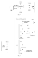
- Fig. 3 is a schematic diagram of an audio signal adapter device according to the second embodiment of the present disclosure. As shown in Fig. 3 , the differences between the audio signal adapter device in the second embodiment and that in the first embodiment are as follows.
- the audio signal adapter device uses the D- pin of the USB plug as the audio signal pin for connecting with the audio output pin of the amplifier, and uses the D+ pin as the reference signal pin for connecting with the ground pin of the MIC and/or the ground pin of the amplifier, so as to output the audio signal to the audio signal receiving device.
- the audio signal receiving device in the second embodiment is the same as that in the first embodiment.
- the system for transmitting the audio signal according to the second embodiment of the present disclosure comprises the above audio signal adapter device and the above audio signal receiving device.
- Fig. 4 is a schematic diagram of an audio signal adapter device according to the third embodiment of the present disclosure. As shown in Fig. 4 , the differences between the audio signal adapter device in the third embodiment and that in the first embodiment are as follows.
- the audio signal adapter device uses the D+ pin of the USB plug as the audio signal pin, so as to output the audio signal to the audio signal receiving device in non-differential manner.
- Fig. 5 is a schematic diagram of an audio signal receiving device according to the third embodiment of the present disclosure.
- the audio signal receiving device comprises a USB interface (such as a USB socket shown in Fig. 5 ) and an audio receiving module.
- the USB socket is configured to be connected with the USB plug of the audio signal adapter device and to receive the audio signal output from the audio signal adapter device.
- the USB socket comprises a power pin (a VBUS pin), a D+ pin, a D- pin and a ground pin.
- An input end of the audio receiving module is connected with the audio signal pin (the D+ pin), and the audio receiving module is configured to receive the audio signal via the audio signal pin (the D+ pin) and to output the audio signal via the output end of the audio receiving module.
- the audio receiving module comprises a direct current signal isolation unit, a first direct current bias unit, a second direct current bias unit and a comparator.
- the direct current signal isolation unit comprises a capacitor C1 for isolating a direct current level.
- a first terminal of the capacitor C1 (an input end of the direct current signal isolation unit) is connected with the audio signal pin, and a second terminal of the capacitor C1 (an output end of the direct current signal isolation unit) is connected with the second direct current bias unit.
- a capacitance of the capacitor C1 may be 0.1 ⁇ F.
- An output end of the first direct current bias unit is connected with a positive terminal of the comparator, and configured to output a reference level to the comparator.
- the first direct current bias unit comprises a resistor R3 and a resistor R4.
- a first terminal of the resistor R3 is connected with a first power supply, and a second terminal of the resistor R3 is connected with the resistor R4.
- a first terminal of the resistor R4 is connected with the resistor R3 and the output end of the first direct current bias unit respectively, and a second terminal of the resistor R4 is grounded.
- the second direct current bias unit is configured to add a direct current bias to the audio signal input from the input end of the second direct current bias unit to obtain a biased audio signal so as to raise a minimum voltage of the audio signal to over 0V, and to output the biased audio signal via the output end of the second direct current bias unit.
- the second direct current bias unit comprises a resistor R5 and a resistor R6.
- a first terminal of the resistor R5 is connected with a second power supply, and a second terminal of the resistor R5 is connected with the resistor R6.
- a first terminal of the resistor R6 is connected with the input end of the second direct current bias unit, the resistor R5 and the output end of the second direct current bias unit respectively, and a second terminal of the resistor R6 is grounded.
- An output voltage of the first power supply in the first direct current bias unit is equal to an output voltage of the second power supply in the second direct current bias unit, a resistance of the resistor R3 is equal to a resistance of the resistor R5, and a resistance of the resistor R4 is equal to a resistance of the resistor R6.
- each of the resistances of the resistor R3 and the resistor R5 may be 150K ⁇ , and each of the resistances of the resistor R4 and the resistor R6 may be 15 K ⁇ .
- the positive terminal of the comparator is connected with the output end of the first direct current bias unit
- the negative terminal of the comparator is connected with the output end of the second direct current bias unit
- an output terminal of the comparator is connected with the output end of the audio receiving module (i.e., used as the output end of the audio receiving module) for outputting a square wave corresponding to the audio signal.
- the output terminal of the comparator is connected with the positive terminal of the comparator via a resistor R7 to form a loop, and the output terminal of the comparator is also connected with a pull-up resistor R8.
- a resistance of the resistor R7 may be 1.5 M ⁇ , and a resistance of the resistor R8 may be 20 K ⁇ .
- the system for transmitting the audio signal according to the third embodiment of the present disclosure comprises the above audio signal adapter device and the above audio signal receiving device.
- Fig. 6 is a schematic diagram of an audio signal adapter device according to the fourth embodiment of the present disclosure. As shown in Fig. 6 , the differences between the audio signal adapter device in the fourth embodiment and that in the third embodiment are as follows.
- the audio signal adapter device uses the D- pin of the USB plug as the audio signal pin for connecting with the audio output pin of the amplifier, so as to output the audio signal to the audio signal receiving device.
- Fig. 7 is a schematic diagram of an audio signal receiving device according to the fourth embodiment of the present disclosure. As shown in Fig. 7 , the differences between the audio signal receiving device in the fourth embodiment and that in the third embodiment are as follows.
- the input end of the audio receiving module is connected with the D- pin, and the audio receiving module is configured to receive the audio signal via the D- pin and to output the audio signal via the output end of the audio receiving module.
- the system for transmitting the audio signal according to the fourth embodiment of the present disclosure comprises the above audio signal adapter device and the above audio signal receiving device.
- the electronic equipment can receive the audio signal output from a loudspeaker via the USB interface with a relatively low hardware cost.
- the electronic equipment can receive the audio signal output from the loudspeaker via the USB interface, without the need of providing a separate loudspeaker interface, and without the need of providing an MIC functional module, thus reducing a cost of the electronic equipment and decreasing a size of the electronic equipment.
- Any procedure or method described in the flow charts or described in any other way herein may be understood to comprise one or more modules, portions or parts for storing executable codes that realize particular logic functions or procedures.
- advantageous embodiments of the present disclosure comprises other implementations in which the order of execution is different from that which is depicted or discussed, including executing functions in a substantially simultaneous manner or in an opposite order according to the related functions. This should be understood by those skilled in the art which embodiments of the present disclosure belong to.
Landscapes
- Physics & Mathematics (AREA)
- Engineering & Computer Science (AREA)
- Acoustics & Sound (AREA)
- Signal Processing (AREA)
- Circuit For Audible Band Transducer (AREA)
Applications Claiming Priority (2)
| Application Number | Priority Date | Filing Date | Title |
|---|---|---|---|
| CN201110201205.2A CN102387429B (zh) | 2011-07-18 | 2011-07-18 | 一种音频信号转接装置、音频信号传输系统 |
| PCT/CN2012/078834 WO2013010487A1 (zh) | 2011-07-18 | 2012-07-18 | 一种音频信号转接装置、音频信号传输系统 |
Publications (2)
| Publication Number | Publication Date |
|---|---|
| EP2736265A1 true EP2736265A1 (de) | 2014-05-28 |
| EP2736265A4 EP2736265A4 (de) | 2015-02-25 |
Family
ID=45826293
Family Applications (1)
| Application Number | Title | Priority Date | Filing Date |
|---|---|---|---|
| EP20120814990 Withdrawn EP2736265A4 (de) | 2011-07-18 | 2012-07-18 | Tonsignaladapter und tonsignalübertragungssystem |
Country Status (5)
| Country | Link |
|---|---|
| US (1) | US9357297B2 (de) |
| EP (1) | EP2736265A4 (de) |
| CN (1) | CN102387429B (de) |
| CA (1) | CA2842254C (de) |
| WO (1) | WO2013010487A1 (de) |
Cited By (1)
| Publication number | Priority date | Publication date | Assignee | Title |
|---|---|---|---|---|
| WO2016110599A1 (en) * | 2015-01-11 | 2016-07-14 | Relish Brothers Ag | Connector for an electric harness conducting electric signals with a frequency of not more than 30khz |
Families Citing this family (6)
| Publication number | Priority date | Publication date | Assignee | Title |
|---|---|---|---|---|
| CN102387429B (zh) * | 2011-07-18 | 2014-04-02 | 天地融科技股份有限公司 | 一种音频信号转接装置、音频信号传输系统 |
| CN104936051B (zh) * | 2015-01-19 | 2018-09-28 | 天地融科技股份有限公司 | 一种耳机、音箱和通话系统 |
| CN109348385B (zh) * | 2018-10-22 | 2024-07-09 | 钰太芯微电子科技(上海)有限公司 | 一种具有回声消声系统的麦克风及电子设备 |
| CN110444221B (zh) * | 2019-09-05 | 2025-02-18 | 成都克伏特航空设备有限公司 | 一种多路语音系统 |
| CN111030465B (zh) * | 2019-12-24 | 2022-07-19 | 深圳市绿联科技股份有限公司 | 一种供电隔离的无线音频接收装置 |
| CN112565978A (zh) * | 2020-11-30 | 2021-03-26 | 江苏云界安全技术有限公司 | 动圈麦克风电路和动圈麦克风 |
Family Cites Families (14)
| Publication number | Priority date | Publication date | Assignee | Title |
|---|---|---|---|---|
| US5914877A (en) * | 1996-10-23 | 1999-06-22 | Advanced Micro Devices, Inc. | USB based microphone system |
| CN2833720Y (zh) * | 2005-05-26 | 2006-11-01 | 台均科技(深圳)有限公司 | 音频/usb信号复用线、播放存储设备及复用传输播放存储系统 |
| CN1774143A (zh) * | 2005-10-13 | 2006-05-17 | 方泰公司 | 一种省去隔直电容的耳机输出电路 |
| CN100388182C (zh) * | 2006-11-23 | 2008-05-14 | 王祥贵 | 带麦克风放大器的usb接口连接线 |
| CN101207256B (zh) * | 2006-12-20 | 2010-09-29 | 鸿富锦精密工业(深圳)有限公司 | 一种音频信号转接装置 |
| CN101217225B (zh) * | 2007-01-05 | 2011-07-27 | 鸿富锦精密工业(深圳)有限公司 | 一种音频信号转接装置 |
| US8064613B1 (en) * | 2008-03-03 | 2011-11-22 | Maxim Integrated Products, Inc. | Electret microphone detection using a current source |
| JP2010251859A (ja) * | 2009-04-10 | 2010-11-04 | Toshiba Corp | 携帯端末 |
| CN201830430U (zh) * | 2010-10-09 | 2011-05-11 | 三星电子株式会社 | 自供电的具有主动噪音消除功能的耳机 |
| CN102065160A (zh) * | 2010-12-02 | 2011-05-18 | 惠州Tcl移动通信有限公司 | 一种利用手机外接扬声器的电路 |
| KR20120068274A (ko) * | 2010-12-17 | 2012-06-27 | 삼성전자주식회사 | 휴대 단말기의 통합 커넥터 장치 및 이의 운용 방법 |
| US9668076B2 (en) * | 2011-06-21 | 2017-05-30 | Apple Inc. | Microphone headset failure detecting and reporting |
| CN102387429B (zh) * | 2011-07-18 | 2014-04-02 | 天地融科技股份有限公司 | 一种音频信号转接装置、音频信号传输系统 |
| CN103512650A (zh) * | 2012-06-21 | 2014-01-15 | 鸿富锦精密工业(深圳)有限公司 | 蜂鸣器测试电路 |
-
2011
- 2011-07-18 CN CN201110201205.2A patent/CN102387429B/zh active Active
-
2012
- 2012-07-18 WO PCT/CN2012/078834 patent/WO2013010487A1/zh not_active Ceased
- 2012-07-18 CA CA2842254A patent/CA2842254C/en active Active
- 2012-07-18 US US14/233,422 patent/US9357297B2/en not_active Expired - Fee Related
- 2012-07-18 EP EP20120814990 patent/EP2736265A4/de not_active Withdrawn
Cited By (1)
| Publication number | Priority date | Publication date | Assignee | Title |
|---|---|---|---|---|
| WO2016110599A1 (en) * | 2015-01-11 | 2016-07-14 | Relish Brothers Ag | Connector for an electric harness conducting electric signals with a frequency of not more than 30khz |
Also Published As
| Publication number | Publication date |
|---|---|
| CA2842254C (en) | 2016-10-18 |
| CA2842254A1 (en) | 2013-01-24 |
| WO2013010487A1 (zh) | 2013-01-24 |
| US9357297B2 (en) | 2016-05-31 |
| US20150036837A1 (en) | 2015-02-05 |
| CN102387429A (zh) | 2012-03-21 |
| CN102387429B (zh) | 2014-04-02 |
| EP2736265A4 (de) | 2015-02-25 |
Similar Documents
| Publication | Publication Date | Title |
|---|---|---|
| US9357297B2 (en) | Audio signal adapter device and system for transmitting audio signal | |
| US9414147B2 (en) | Method and device for earphone and USB to share micro-USB interface | |
| EP2863652B1 (de) | Selbstadaptionsvorrichtung für audioschnittstelle | |
| US9215541B2 (en) | Apparatus for detecting type of audio interface | |
| CN102201826B (zh) | 一种音频信号转接及接收装置,音频信号传输系统 | |
| CN203872341U (zh) | 一种音频通信耳机插口麦克风线序自动匹配电路 | |
| EP2722939A1 (de) | Tonsignalempfangs- und übertragungsvorrichtung | |
| CN104244160A (zh) | 可通过耳机接口进行调试的电子装置 | |
| CN101207256B (zh) | 一种音频信号转接装置 | |
| US9179216B2 (en) | Audio interface adapter device and audio signal receiving apparatus | |
| CN203057324U (zh) | 一种控制装置、数字电视终端及系统 | |
| EP2383860B1 (de) | Schnellladegerät | |
| US7755221B2 (en) | Electronic device with compound audio interface and power adapter | |
| CN105530559A (zh) | 蓝牙耳机 | |
| CN101593905A (zh) | 连接器装置 | |
| US20150208164A1 (en) | Downlink transmission device for audio signals and electronic signature token | |
| CN213026812U (zh) | 一种具有多功能连接器的音频设备 | |
| CN206148769U (zh) | 数字音频转换接头 | |
| CN206742616U (zh) | 转接线 | |
| CN202889563U (zh) | 一种usb供电的无线麦克风接收器 | |
| CN202197391U (zh) | 可实现共用声源的耳机 | |
| HK1184945B (en) | Audio interface adapting device and audio signal receiving apparatus | |
| KR20170101450A (ko) | 이어 마이크 |
Legal Events
| Date | Code | Title | Description |
|---|---|---|---|
| PUAI | Public reference made under article 153(3) epc to a published international application that has entered the european phase |
Free format text: ORIGINAL CODE: 0009012 |
|
| 17P | Request for examination filed |
Effective date: 20140128 |
|
| AK | Designated contracting states |
Kind code of ref document: A1 Designated state(s): AL AT BE BG CH CY CZ DE DK EE ES FI FR GB GR HR HU IE IS IT LI LT LU LV MC MK MT NL NO PL PT RO RS SE SI SK SM TR |
|
| DAX | Request for extension of the european patent (deleted) | ||
| A4 | Supplementary search report drawn up and despatched |
Effective date: 20150123 |
|
| RIC1 | Information provided on ipc code assigned before grant |
Ipc: H04R 1/08 20060101AFI20150119BHEP |
|
| 17Q | First examination report despatched |
Effective date: 20160225 |
|
| STAA | Information on the status of an ep patent application or granted ep patent |
Free format text: STATUS: THE APPLICATION IS DEEMED TO BE WITHDRAWN |
|
| 18D | Application deemed to be withdrawn |
Effective date: 20160707 |