EP2736162A2 - Method and apparatus for maximising energy efficiency of an electric drive system - Google Patents
Method and apparatus for maximising energy efficiency of an electric drive system Download PDFInfo
- Publication number
- EP2736162A2 EP2736162A2 EP13193407.7A EP13193407A EP2736162A2 EP 2736162 A2 EP2736162 A2 EP 2736162A2 EP 13193407 A EP13193407 A EP 13193407A EP 2736162 A2 EP2736162 A2 EP 2736162A2
- Authority
- EP
- European Patent Office
- Prior art keywords
- torque
- motor
- basis
- parameter
- rotational speed
- Prior art date
- Legal status (The legal status is an assumption and is not a legal conclusion. Google has not performed a legal analysis and makes no representation as to the accuracy of the status listed.)
- Granted
Links
Images

Classifications
-
- B—PERFORMING OPERATIONS; TRANSPORTING
- B60—VEHICLES IN GENERAL
- B60L—PROPULSION OF ELECTRICALLY-PROPELLED VEHICLES; SUPPLYING ELECTRIC POWER FOR AUXILIARY EQUIPMENT OF ELECTRICALLY-PROPELLED VEHICLES; ELECTRODYNAMIC BRAKE SYSTEMS FOR VEHICLES IN GENERAL; MAGNETIC SUSPENSION OR LEVITATION FOR VEHICLES; MONITORING OPERATING VARIABLES OF ELECTRICALLY-PROPELLED VEHICLES; ELECTRIC SAFETY DEVICES FOR ELECTRICALLY-PROPELLED VEHICLES
- B60L15/00—Methods, circuits, or devices for controlling the traction-motor speed of electrically-propelled vehicles
- B60L15/20—Methods, circuits, or devices for controlling the traction-motor speed of electrically-propelled vehicles for control of the vehicle or its driving motor to achieve a desired performance, e.g. speed, torque, programmed variation of speed
-
- H—ELECTRICITY
- H02—GENERATION; CONVERSION OR DISTRIBUTION OF ELECTRIC POWER
- H02P—CONTROL OR REGULATION OF ELECTRIC MOTORS, ELECTRIC GENERATORS OR DYNAMO-ELECTRIC CONVERTERS; CONTROLLING TRANSFORMERS, REACTORS OR CHOKE COILS
- H02P6/00—Arrangements for controlling synchronous motors or other dynamo-electric motors using electronic commutation dependent on the rotor position; Electronic commutators therefor
-
- H—ELECTRICITY
- H02—GENERATION; CONVERSION OR DISTRIBUTION OF ELECTRIC POWER
- H02P—CONTROL OR REGULATION OF ELECTRIC MOTORS, ELECTRIC GENERATORS OR DYNAMO-ELECTRIC CONVERTERS; CONTROLLING TRANSFORMERS, REACTORS OR CHOKE COILS
- H02P23/00—Arrangements or methods for the control of AC motors characterised by a control method other than vector control
- H02P23/0004—Control strategies in general, e.g. linear type, e.g. P, PI, PID, using robust control
-
- H—ELECTRICITY
- H02—GENERATION; CONVERSION OR DISTRIBUTION OF ELECTRIC POWER
- H02P—CONTROL OR REGULATION OF ELECTRIC MOTORS, ELECTRIC GENERATORS OR DYNAMO-ELECTRIC CONVERTERS; CONTROLLING TRANSFORMERS, REACTORS OR CHOKE COILS
- H02P27/00—Arrangements or methods for the control of AC motors characterised by the kind of supply voltage
- H02P27/04—Arrangements or methods for the control of AC motors characterised by the kind of supply voltage using variable-frequency supply voltage, e.g. inverter or converter supply voltage
-
- Y—GENERAL TAGGING OF NEW TECHNOLOGICAL DEVELOPMENTS; GENERAL TAGGING OF CROSS-SECTIONAL TECHNOLOGIES SPANNING OVER SEVERAL SECTIONS OF THE IPC; TECHNICAL SUBJECTS COVERED BY FORMER USPC CROSS-REFERENCE ART COLLECTIONS [XRACs] AND DIGESTS
- Y02—TECHNOLOGIES OR APPLICATIONS FOR MITIGATION OR ADAPTATION AGAINST CLIMATE CHANGE
- Y02P—CLIMATE CHANGE MITIGATION TECHNOLOGIES IN THE PRODUCTION OR PROCESSING OF GOODS
- Y02P80/00—Climate change mitigation technologies for sector-wide applications
- Y02P80/10—Efficient use of energy, e.g. using compressed air or pressurized fluid as energy carrier
-
- Y—GENERAL TAGGING OF NEW TECHNOLOGICAL DEVELOPMENTS; GENERAL TAGGING OF CROSS-SECTIONAL TECHNOLOGIES SPANNING OVER SEVERAL SECTIONS OF THE IPC; TECHNICAL SUBJECTS COVERED BY FORMER USPC CROSS-REFERENCE ART COLLECTIONS [XRACs] AND DIGESTS
- Y02—TECHNOLOGIES OR APPLICATIONS FOR MITIGATION OR ADAPTATION AGAINST CLIMATE CHANGE
- Y02T—CLIMATE CHANGE MITIGATION TECHNOLOGIES RELATED TO TRANSPORTATION
- Y02T10/00—Road transport of goods or passengers
- Y02T10/60—Other road transportation technologies with climate change mitigation effect
- Y02T10/72—Electric energy management in electromobility
Definitions
- the present invention relates to electric drive systems, particularly to maximising energy efficiency of an electric drive system.
- Manufacturers of present-day frequency converters can utilise various techniques in controlling behaviour of a torque of a motor in respect to a rotational speed of the motor in an electric drive application.
- the applications can, for example, be divided into two groups on the basis of the behaviour of the load: linear torque/speed ratio applications and quadratic torque/speed ratio applications.
- linear (torque/speed ratio) applications the torque applied to the load is directly proportional to the rotational speed.
- quadratic (torque/speed ratio) applications the torque is proportional to the square of the rotational speed.
- one of the above approaches i.e. a more dynamic performance or a more economic performance, may be selected as the default performance approach, and the other may be selected by the user. The user does not, however, always select the more appropriate approach for the application in question.
- An object of the present invention is to provide a method and an apparatus for implementing the method so as to alleviate the above disadvantages.
- the objects of the invention are achieved by a method and an arrangement which are characterized by what is stated in the independent claims.
- the preferred embodiments of the invention are disclosed in the dependent claims.
- the disclosed method allows automatised selection of the operating mode, i.e. a dynamic performance mode where a nominal flux is used or an economic performance mode where the flux is limited in order to achieve energy savings.
- the disclosed method first gathers a set of data points of torques at different rotational speeds. Then, the method calculates with which behaviour of the load, i.e. the linear behaviour or the quadratic behaviour, the data points have better correlation. On the basis of the result of this calculation, one of the two torque/speed behaviours is selected to represent the torque characteristics of the system, and the motor is controlled on the basis of the selected behaviour. As the behaviour is automatically determined, selecting a more appropriate operating mode does not have to rely on user input.
- the present disclosure discloses a method for maximising energy efficiency of an electric drive system comprising an electric motor and a load.
- the disclosed method allows automatic detection of different behaviours of torque of the motor in respect to a rotational speed of the motor, i.e. detection of different torque/speed ratios.
- the torque characteristics of the system may be selected from two types of behaviour: linear behaviour and quadratic behaviour of the torque in respect to the rotational speed.
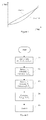
- Figure 1 illustrates the linear and quadratic system behaviour of a torque in respect to a rotational speed.
- the linear behaviour (dotted line) represents a situation where the torque T is directly proportional to the rotational speed f.
- T af + b , where a is a coefficient which represents the relation between the torque and the rotational speed, and b represents a constant torque which is independent from the rotational speed.
- a represents the relation between the torque and the rotational speed
- b represents a constant torque which is independent from the rotational speed.
- the disclosed method automatically determines torque characteristics of the system in question, i.e. which of Equations (1) and (2) better describes the system.
- the motor can then be controlled on the basis of the determined torque characteristics.
- Determining torque characteristics may, for example, comprise first determining the torque of the motor and the rotational speed of the motor.
- the torque and rotational speed may be directly measured, or they may also be estimated, for example, by a frequency converter controlling the motor. If information on how much power is supplied to the motor is available, the torque can be calculated from the power.
- the rotational speed may be determined from the output frequency of the frequency converter.
- the disclosed method may then gather a plurality of data points, where each data point represents the torque of the motor at a rotational speed of the motor.
- a value for a first parameter may be calculated.
- the first parameter represents how much the data points deviate from the quadratic behaviour.
- a value for a second parameter is also calculated on the basis of the data points.
- the second parameter represents how much the data points deviate from the linear behaviour. Then, the first parameter may be compared with the second parameter, and the torque characteristics may be determined on the basis of the comparison.
- the motor may be controlled on the basis of the determined torque characteristics.
- the operating mode i.e. the dynamic performance mode where the flux is not limited or the economic performance mode where the flux is limited in order to improve energy efficiency, can be chosen.
- determining the torque characteristics can also be accomplished by monitoring the rate of change of the torque reference or the difference between the torque reference and the actual torque.
- the magnitude of the rate of change of the torque reference may first be determined. The magnitude may then be compared with a set limit, and if the magnitude exceeds the set limit, the electric drive can be set to the dynamic performance mode.
- the torque of the motor may first be determined.
- the difference between the torque reference and the determined torque may then be determined and compared with a set limit. If the difference exceeds the set limit, the electric drive is set to the dynamic performance mode.
- Figure 2 illustrates a flowchart of an exemplary implementation of the disclosed method.
- the torque and the rotational speed are measured and data points are gathered.
- the value for a first parameter is calculated.
- Two equations are formed on the basis of two data points, for example ( T 1 , f 1 ) and ( T 2 , f 2 ).
- the torque is represented by the square of the rotational speed multiplied by a first coefficient and incremented by a second coefficient.
- a sq T 1 - T 2 f 1 2 - f 2 2
- b sq T 2 ⁇ f 1 2 - T 1 ⁇ f 2 2 f 1 2 - f 2 2 .
- an expected torque T 3 sq for the rotational speed in the third data may be calculated.
- T 3 ⁇ sq a sq ⁇ f 3 2 + b sq .
- the difference between the expected torque T 3 sq and the torque T 3 at the third data point may then be calculated, and the magnitude
- the value for a second parameter is calculated.
- Calculating the value for the second parameter in the third step 23 can be performed in a similar manner to that in the second step 22.
- Two equations are formed on the basis of two data points, for example ( T 1 , f 1 ) and ( T 2 , f 2 ).
- the torque is represented by the rotational speed multiplied by a first coefficient and incremented by a second coefficient.
- T 1 a lin ⁇ f 1 + b lin
- T 2 a lin ⁇ f 2 + b lin .
- the difference between the expected torque T 3 lin and the torque T 3 at the third data point may then be calculated, and the magnitude
- of the difference may be used as the value of the second parameter.
- the first parameter is compared with the second parameter and the torque characteristics of the system are determined on the basis of the comparison.
- the behaviour i.e the linear or quadratic torque/speed ratio, which better fits the data points may be selected as the system torque characteristics.
- Calculation of the first and the second parameter is not, however, limited to the above examples.
- the method of least squares may, for example, be used.
- the data points may be fitted to Equations (1) and (2) by using the method of least squares and the torque characteristics to be used may then be selected on the basis of the best fit.
- the method of least squares is computationally somewhat more complex than the three-point curve fitting as disclosed in Equations (3) to (12).
- FIG 3 illustrates an apparatus 31 for maximising energy efficiency of an electric drive system comprising an electric motor 32 and a load 33.
- the load 33 in Figure 3 is a fan which is rotated by the motor 32.
- the apparatus 31 in Figure 3 is a frequency converter which controls the motor 32 and implements the disclosed method.
- the frequency converter 31 automatically selects appropriate torque characteristics to be used, depending on the application.
- the torque characteristics in the frequency converter 31 may be selected from two types of behaviour: linear and quadratic behaviour of a torque of the motor in respect to a rotational speed of the motor.
- the frequency converter 31 acts as means for determining a torque of the motor and a rotational speed of the motor. In Figure 3 , it has internal estimates of said variables.
- the frequency converter 31 gathers a plurality of data points to its internal memory. Each data point represents the torque of the motor at a rotational speed of the motor.
- the frequency converter 31 in Figure 3 comprises computing means, such as a microprocessor, a DSP, an FPGA, or an ASIC, which are used for calculating the value for a first and a second parameter on the basis of the data points.
- the first parameter represents how much the data points deviate from the quadratic behaviour of the torque
- the second parameter represents how much the data points deviate from the linear behaviour of the torque.
- the calculation of the values for the first parameter and the second parameter can, for example, be performed as disclosed in the exemplary implementation of Figure 2 .
- the computing means of the frequency converter 31 After calculating the first and the second parameter, the computing means of the frequency converter 31 compare the first parameter with the second parameter, and determine the torque characteristics on the basis of the comparison. The frequency converter 31 then controls the motor by using determined torque characteristics.
- the apparatus for maximising the energy efficiency may also be an external device attached to a frequency converter.
- the apparatus may determine the behaviour of the system as disclosed above and may then set the frequency converter to an appropriate operating mode, i.e. the dynamic performance mode or the economic performance mode.
Landscapes
- Engineering & Computer Science (AREA)
- Power Engineering (AREA)
- Transportation (AREA)
- Mechanical Engineering (AREA)
- Control Of Electric Motors In General (AREA)
- Control Of Ac Motors In General (AREA)
Abstract
Description
- The present invention relates to electric drive systems, particularly to maximising energy efficiency of an electric drive system.
- Manufacturers of present-day frequency converters can utilise various techniques in controlling behaviour of a torque of a motor in respect to a rotational speed of the motor in an electric drive application.
- The applications can, for example, be divided into two groups on the basis of the behaviour of the load: linear torque/speed ratio applications and quadratic torque/speed ratio applications. In linear (torque/speed ratio) applications, the torque applied to the load is directly proportional to the rotational speed. In quadratic (torque/speed ratio) applications, the torque is proportional to the square of the rotational speed.
- Some linear applications, such as constant-torque loads typically found in industrial applications, may require high dynamic performance. In order to be able to maintain a full torque output from the motor at various motor speeds, the drive provides the motor with a nominal flux.
- However, in some quadratic applications, such as pump or fan applications, the dynamic performance requirements may not be as demanding as in linear applications. In such applications, the flux applicable by the drive can be limited, allowing thus more economic performance. On the other hand, this approach may result in a reduced dynamic performance of the drive, as there is a more limited flux capability available than with the nominal flux.
- In some frequency converters, one of the above approaches, i.e. a more dynamic performance or a more economic performance, may be selected as the default performance approach, and the other may be selected by the user. The user does not, however, always select the more appropriate approach for the application in question.
- An object of the present invention is to provide a method and an apparatus for implementing the method so as to alleviate the above disadvantages. The objects of the invention are achieved by a method and an arrangement which are characterized by what is stated in the independent claims. The preferred embodiments of the invention are disclosed in the dependent claims.
- The disclosed method allows automatised selection of the operating mode, i.e. a dynamic performance mode where a nominal flux is used or an economic performance mode where the flux is limited in order to achieve energy savings.
- The disclosed method first gathers a set of data points of torques at different rotational speeds. Then, the method calculates with which behaviour of the load, i.e. the linear behaviour or the quadratic behaviour, the data points have better correlation. On the basis of the result of this calculation, one of the two torque/speed behaviours is selected to represent the torque characteristics of the system, and the motor is controlled on the basis of the selected behaviour. As the behaviour is automatically determined, selecting a more appropriate operating mode does not have to rely on user input.
- In the following the invention will be described in greater detail by means of preferred embodiments with reference to the attached drawings, in which
-
Figure 1 illustrates linear and quadratic behaviour of a torque in respect to a rotational speed; -
Figure 2 illustrates a flowchart of an exemplary implementation of the disclosed method; and -
Figure 3 illustrates an apparatus for maximising energy efficiency of an electric drive system comprising an electric motor and a load. - The present disclosure discloses a method for maximising energy efficiency of an electric drive system comprising an electric motor and a load. The disclosed method allows automatic detection of different behaviours of torque of the motor in respect to a rotational speed of the motor, i.e. detection of different torque/speed ratios.
- In the disclosed method, the torque characteristics of the system may be selected from two types of behaviour: linear behaviour and quadratic behaviour of the torque in respect to the rotational speed.
-
Figure 1 illustrates the linear and quadratic system behaviour of a torque in respect to a rotational speed. The linear behaviour (dotted line) represents a situation where the torque T is directly proportional to the rotational speed f.
where a is a coefficient which represents the relation between the torque and the rotational speed, and b represents a constant torque which is independent from the rotational speed. - The quadratic behaviour (dashed line) represents a situation where the torque is proportional to the square of the rotational speed f:

Again, a represents the relation between the torque and the rotational speed, and b represents a constant torque which is independent from the rotational speed. - In order to be able to maximise the energy efficiency, the disclosed method automatically determines torque characteristics of the system in question, i.e. which of Equations (1) and (2) better describes the system. The motor can then be controlled on the basis of the determined torque characteristics.
- Determining torque characteristics may, for example, comprise first determining the torque of the motor and the rotational speed of the motor. The torque and rotational speed may be directly measured, or they may also be estimated, for example, by a frequency converter controlling the motor. If information on how much power is supplied to the motor is available, the torque can be calculated from the power. The rotational speed may be determined from the output frequency of the frequency converter.
- The disclosed method may then gather a plurality of data points, where each data point represents the torque of the motor at a rotational speed of the motor.
- On the basis of the data points, a value for a first parameter may be calculated. The first parameter represents how much the data points deviate from the quadratic behaviour. A value for a second parameter is also calculated on the basis of the data points. The second parameter, in turn, represents how much the data points deviate from the linear behaviour. Then, the first parameter may be compared with the second parameter, and the torque characteristics may be determined on the basis of the comparison.
- When the torque characteristics have been determined, the motor may be controlled on the basis of the determined torque characteristics. On the basis of the torque characteristics, the operating mode, i.e. the dynamic performance mode where the flux is not limited or the economic performance mode where the flux is limited in order to improve energy efficiency, can be chosen.
- If the electric drive system is controlled on the basis of a torque reference, and if the electric drive can initially bet set to the economic performance mode, determining the torque characteristics can also be accomplished by monitoring the rate of change of the torque reference or the difference between the torque reference and the actual torque.
- For example, the magnitude of the rate of change of the torque reference may first be determined. The magnitude may then be compared with a set limit, and if the magnitude exceeds the set limit, the electric drive can be set to the dynamic performance mode.
- Alternatively, the torque of the motor may first be determined. The difference between the torque reference and the determined torque may then be determined and compared with a set limit. If the difference exceeds the set limit, the electric drive is set to the dynamic performance mode.
-
Figure 2 illustrates a flowchart of an exemplary implementation of the disclosed method. In thefirst step 21 the torque and the rotational speed are measured and data points are gathered. - In the
second step 22, the value for a first parameter is calculated. Two equations are formed on the basis of two data points, for example (T 1 , f 1) and (T 2, f 2). For each data point, the torque is represented by the square of the rotational speed multiplied by a first coefficient and incremented by a second coefficient. The equations for the two data points (T 1 , f 1) and (T 2, f 2) have the same coefficients asq and bsq :

- The values of the coefficients asq and bsq may then be solved as follows:


- On the basis of the coefficients asq and bsq and the rotational speed f 3 at a third data point, an expected torque T 3sq for the rotational speed in the third data may be calculated.

- The difference between the expected torque T 3sq and the torque T 3 at the third data point may then be calculated, and the magnitude |T 3 - T 3 sq | of the difference may be used as the value of the first parameter.
- In the
third step 23, the value for a second parameter is calculated. Calculating the value for the second parameter in thethird step 23 can be performed in a similar manner to that in thesecond step 22. Two equations are formed on the basis of two data points, for example (T 1 , f 1) and (T 2, f 2). For both data points, the torque is represented by the rotational speed multiplied by a first coefficient and incremented by a second coefficient. The equations for the two data points (T 1 , f 1) and (T 2 , f 2) have the same coefficients alin and blin :

- Values of the coefficients alin and blin may be solved as follows:


- An expected torque T 3lin for a rotational speed at the third data point is calculated on the basis of the coefficients alin and blin and the rotational speed f 3 at the third data point:

- The difference between the expected torque T 3lin and the torque T 3 at the third data point may then be calculated, and the magnitude |T 3 -T 3lin | of the difference may be used as the value of the second parameter.
- In the
fourth step 24 inFigure 1 , the first parameter is compared with the second parameter and the torque characteristics of the system are determined on the basis of the comparison. The behaviour, i.e the linear or quadratic torque/speed ratio, which better fits the data points may be selected as the system torque characteristics. - Finally, in
fifth step 25, the motor is controlled on the basis of the determined torque characteristics. - Calculation of the first and the second parameter is not, however, limited to the above examples. In some applications, where accurate measurements are not easily obtained, the method of least squares may, for example, be used. For example, the data points may be fitted to Equations (1) and (2) by using the method of least squares and the torque characteristics to be used may then be selected on the basis of the best fit. On the other hand, the method of least squares is computationally somewhat more complex than the three-point curve fitting as disclosed in Equations (3) to (12).
-
Figure 3 illustrates anapparatus 31 for maximising energy efficiency of an electric drive system comprising anelectric motor 32 and a load 33. The load 33 inFigure 3 is a fan which is rotated by themotor 32. Theapparatus 31 inFigure 3 is a frequency converter which controls themotor 32 and implements the disclosed method. Thefrequency converter 31 automatically selects appropriate torque characteristics to be used, depending on the application. The torque characteristics in thefrequency converter 31 may be selected from two types of behaviour: linear and quadratic behaviour of a torque of the motor in respect to a rotational speed of the motor. - The
frequency converter 31 acts as means for determining a torque of the motor and a rotational speed of the motor. InFigure 3 , it has internal estimates of said variables. Thefrequency converter 31 gathers a plurality of data points to its internal memory. Each data point represents the torque of the motor at a rotational speed of the motor. - The
frequency converter 31 inFigure 3 comprises computing means, such as a microprocessor, a DSP, an FPGA, or an ASIC, which are used for calculating the value for a first and a second parameter on the basis of the data points. The first parameter represents how much the data points deviate from the quadratic behaviour of the torque, and the second parameter represents how much the data points deviate from the linear behaviour of the torque. The calculation of the values for the first parameter and the second parameter can, for example, be performed as disclosed in the exemplary implementation ofFigure 2 . - After calculating the first and the second parameter, the computing means of the
frequency converter 31 compare the first parameter with the second parameter, and determine the torque characteristics on the basis of the comparison. Thefrequency converter 31 then controls the motor by using determined torque characteristics. - The apparatus for maximising the energy efficiency may also be an external device attached to a frequency converter. The apparatus may determine the behaviour of the system as disclosed above and may then set the frequency converter to an appropriate operating mode, i.e. the dynamic performance mode or the economic performance mode.
- It will be obvious to a person skilled in the art that the inventive concept can be implemented in various ways. The invention and its embodiments are not limited to the examples described above but may vary within the scope of the claims.
Claims (8)
- A method for maximising energy efficiency of an electric drive system comprising an electric motor and a load, wherein the method comprises
determining torque characteristics of the system, wherein the torque characteristics are selected from two types of behaviour: linear or quadratic behaviour of a torque of the motor in respect to a rotational speed of the motor, and
controlling the motor on the basis of the determined torque characteristics. - A method as claimed in claim 1, wherein determining the torque characteristics comprises
determining a torque of the motor and a rotational speed of the motor,
gathering a plurality of data points, wherein each data point represents the torque of the motor at the rotational speed of the motor,
calculating a value for a first parameter on the basis of the data points, wherein the first parameter represents how much the data points deviate from the quadratic behaviour of the torque,
calculating a value for a second parameter on the basis of the data points, wherein the second parameter represents how much the data points deviate from the linear behaviour of the torque,
comparing the first parameter with the second parameter, and determining the torque characteristics on the basis of the comparison. - A method as claimed in claim 2, wherein calculating the value for the first parameter comprises
forming two equations on the basis of two data points, wherein, for each data point, the torque is the square of the rotational speed multiplied by a first coefficient and incremented by a second coefficient, and wherein both equations have the same coefficients,
solving the values of the coefficients,
calculating an expected torque for a rotational speed at a third data point on the basis of the coefficients and the rotational speed at the third data point,
calculating the difference between the expected torque and the torque at the third data point, and
using the difference as the value of the first parameter, and wherein calculating the value for the second parameter comprises
forming two equations on the basis of two data points, wherein, for each data point, the torque is the rotational speed multiplied by a first coefficient and incremented by a second coefficient, and wherein both equations have the same coefficients,
solving the coefficients,
calculating an expected torque for a rotational speed at a third data point on the basis of the coefficients and the rotational speed at the third data point,
calculating the difference between the expected torque and the torque at the third data point, and
using the difference as the value of the second parameter. - A method as claimed in claim 2 or 3, wherein the torque is calculated from a determined power supplied to the motor.
- A method as claimed in claim 1, wherein the electric drive system is controlled on the basis of a torque reference, wherein the electric drive is initially set to an economic performance mode where the flux is limited in order to achieve energy savings, and wherein determining the torque characteristics comprises
determining the magnitude of the rate of change of the torque reference,
comparing the magnitude with a set limit, and if the magnitude exceeds the set limit,
setting the electric drive to a dynamic performance mode where the flux is not limited. - A method as claimed in claim 1, wherein the electric drive system is controlled on the basis of a torque reference, wherein the electric drive is initially set to an economic performance mode where the flux is limited in order to improve energy efficiency, and wherein determining the torque characteristics comprises
determining a torque of the motor,
determining the difference between the torque reference and the determined torque,
comparing the difference with a set limit, and if the difference exceeds the set limit,
setting the electric drive to a dynamic performance mode where the flux is not limited. - An apparatus for maximising energy efficiency of an electric drive system comprising an electric motor and a load, wherein the apparatus comprises
means for determining the torque characteristics, wherein the torque characteristics of the system are selected from two types of behaviour: linear and quadratic behaviour of a torque of the motor in respect to a rotational speed of the motor, and
means for controlling the motor on the basis of the determined torque characteristics. - An apparatus as claimed in claim 7, wherein the means for determining the torque characteristics comprise
means for determining a torque of the motor and a rotational speed of the motor,
means for gathering a plurality of data points, wherein each data point represents the torque of the motor at the rotational speed of the motor,
means for calculating a value for a first parameter on the basis of the data points, wherein the first parameter represents how much the data points deviate from the quadratic behaviour of the torque,
means for calculating a value for a second parameter on the basis of the data points, wherein the second parameter represents how much the data points deviate from the linear behaviour of the torque,
means for comparing the first parameter with the second parameter, means for determining the torque characteristics on the basis of the comparison, and
means for controlling the motor on the basis of the determined torque characteristics.
Applications Claiming Priority (1)
| Application Number | Priority Date | Filing Date | Title |
|---|---|---|---|
| FI20126222A FI124819B (en) | 2012-11-21 | 2012-11-21 | Method and apparatus for maximizing energy efficiency for electric power systems |
Publications (3)
| Publication Number | Publication Date |
|---|---|
| EP2736162A2 true EP2736162A2 (en) | 2014-05-28 |
| EP2736162A3 EP2736162A3 (en) | 2017-09-06 |
| EP2736162B1 EP2736162B1 (en) | 2019-11-13 |
Family
ID=49619822
Family Applications (1)
| Application Number | Title | Priority Date | Filing Date |
|---|---|---|---|
| EP13193407.7A Active EP2736162B1 (en) | 2012-11-21 | 2013-11-19 | Method and apparatus for maximising energy efficiency of an electric drive system |
Country Status (5)
| Country | Link |
|---|---|
| US (1) | US9216662B2 (en) |
| EP (1) | EP2736162B1 (en) |
| CN (1) | CN103840734B (en) |
| DK (1) | DK2736162T3 (en) |
| FI (1) | FI124819B (en) |
Families Citing this family (2)
| Publication number | Priority date | Publication date | Assignee | Title |
|---|---|---|---|---|
| CN109017450B (en) * | 2016-12-14 | 2020-07-21 | 大连民族大学 | Four-wheel independent drive electric vehicle torque distribution method |
| CN107826119B (en) * | 2017-11-15 | 2019-11-22 | 康明斯天远(河北)科技有限公司 | A kind of conduct monitoring at all levels and evaluation method of driving behavior |
Family Cites Families (13)
| Publication number | Priority date | Publication date | Assignee | Title |
|---|---|---|---|---|
| US5239251A (en) | 1989-06-30 | 1993-08-24 | The State Of Oregon Acting By And Through The State Board Of Higher Education On Behalf Of Oregon State University | Brushless doubly-fed motor control system |
| US5272429A (en) | 1990-10-01 | 1993-12-21 | Wisconsin Alumni Research Foundation | Air gap flux measurement using stator third harmonic voltage and uses |
| JP2000217208A (en) * | 1999-01-21 | 2000-08-04 | Tcm Corp | Structure and method for controlling accelerator of motor-driven industrial vehicle |
| JP3818086B2 (en) | 2001-06-01 | 2006-09-06 | 株式会社日立製作所 | Synchronous motor drive |
| JP3864950B2 (en) * | 2003-11-18 | 2007-01-10 | 日産自動車株式会社 | Hybrid transmission |
| US7192374B2 (en) * | 2004-06-14 | 2007-03-20 | Caterpillar Inc | System and method for controlling a continuously variable transmission |
| KR100815307B1 (en) * | 2006-08-08 | 2008-03-19 | 현대자동차주식회사 | Power Train of Hybrid Vehicle |
| US8138703B2 (en) | 2007-11-04 | 2012-03-20 | GM Global Technology Operations LLC | Method and apparatus for constraining output torque in a hybrid powertrain system |
| JP5252372B2 (en) | 2008-10-01 | 2013-07-31 | 株式会社安川電機 | Synchronous motor control device and control method thereof |
| JP5407322B2 (en) * | 2008-12-22 | 2014-02-05 | トヨタ自動車株式会社 | AC motor control system |
| US8232760B2 (en) * | 2009-06-11 | 2012-07-31 | Easton Corporation | System and method of dynamic regulation of real power to a load |
| JP5623757B2 (en) * | 2010-02-23 | 2014-11-12 | 山洋電気株式会社 | Motor control method and apparatus |
| US8648555B2 (en) * | 2011-02-28 | 2014-02-11 | Deere & Company | Method and system for controlling an electric motor at or near stall conditions |
-
2012
- 2012-11-21 FI FI20126222A patent/FI124819B/en active IP Right Grant
-
2013
- 2013-11-19 EP EP13193407.7A patent/EP2736162B1/en active Active
- 2013-11-19 DK DK13193407.7T patent/DK2736162T3/en active
- 2013-11-21 CN CN201310594336.0A patent/CN103840734B/en active Active
- 2013-11-21 US US14/086,559 patent/US9216662B2/en active Active
Non-Patent Citations (1)
| Title |
|---|
| None |
Also Published As
| Publication number | Publication date |
|---|---|
| US9216662B2 (en) | 2015-12-22 |
| US20140142794A1 (en) | 2014-05-22 |
| DK2736162T3 (en) | 2020-02-24 |
| CN103840734A (en) | 2014-06-04 |
| EP2736162B1 (en) | 2019-11-13 |
| FI124819B (en) | 2015-02-13 |
| FI20126222L (en) | 2014-05-22 |
| CN103840734B (en) | 2016-08-24 |
| EP2736162A3 (en) | 2017-09-06 |
Similar Documents
| Publication | Publication Date | Title |
|---|---|---|
| CN103931096B (en) | Method and system with function of temperature compensation control motor | |
| US9709444B2 (en) | Motor controller, electric vehicle, and heat stress estimation method for switching element | |
| CN102201777B (en) | Control device and control method of induction motor | |
| EP2464002B1 (en) | Estimation of actual torque in an electrical motor drive | |
| US8203298B2 (en) | System and method for motor speed estimation of an electric motor | |
| EP2827493B1 (en) | Device for controlling electric motor and method for controlling electric motor | |
| KR101470025B1 (en) | Method of Controlling Angular Position Sensorlessness of High Efficiency Permanent Magnet Synchronous Motor for Emergency Operation | |
| EP2827492A1 (en) | Device for controlling electric motor and method for controlling electric motor | |
| EP2681838B1 (en) | Interior permanent magnet machine systems | |
| EP2804310A1 (en) | Inverter control device | |
| CN106026820B (en) | Method and system for automatically tuning motor parameters | |
| JP7162759B2 (en) | electric motor drive | |
| EP2945280A2 (en) | Apparatus for controlling induction machine | |
| US9509238B2 (en) | Method and system for traction motor torque ripple compensation | |
| JP6241331B2 (en) | Electric motor control device | |
| US20040090205A1 (en) | Systems and methods for electric motor control | |
| EP2736162A2 (en) | Method and apparatus for maximising energy efficiency of an electric drive system | |
| EP2940858B1 (en) | Motor control device and motor control method | |
| EP2618480A2 (en) | Motor control device and air conditioner | |
| EP4085524A1 (en) | Method for online direct estimation and compensation of flux and torque errors in electric drives | |
| CN102656795A (en) | Motor control system for a hoist drive | |
| EP3507898B1 (en) | Techniques for limiting electrical current provided to a motor in an electric power steering system | |
| US20190190760A1 (en) | Method and Apparatus for Determining Peak Power, Peak-To-Average Power Ratio | |
| EP2922168A1 (en) | Control method for a plurality of generators and system | |
| JP6693442B2 (en) | Motor drive |
Legal Events
| Date | Code | Title | Description |
|---|---|---|---|
| PUAI | Public reference made under article 153(3) epc to a published international application that has entered the european phase |
Free format text: ORIGINAL CODE: 0009012 |
|
| 17P | Request for examination filed |
Effective date: 20131119 |
|
| AK | Designated contracting states |
Kind code of ref document: A2 Designated state(s): AL AT BE BG CH CY CZ DE DK EE ES FI FR GB GR HR HU IE IS IT LI LT LU LV MC MK MT NL NO PL PT RO RS SE SI SK SM TR |
|
| AX | Request for extension of the european patent |
Extension state: BA ME |
|
| PUAL | Search report despatched |
Free format text: ORIGINAL CODE: 0009013 |
|
| AK | Designated contracting states |
Kind code of ref document: A3 Designated state(s): AL AT BE BG CH CY CZ DE DK EE ES FI FR GB GR HR HU IE IS IT LI LT LU LV MC MK MT NL NO PL PT RO RS SE SI SK SM TR |
|
| AX | Request for extension of the european patent |
Extension state: BA ME |
|
| RIC1 | Information provided on ipc code assigned before grant |
Ipc: H02P 6/00 20160101AFI20170803BHEP |
|
| STAA | Information on the status of an ep patent application or granted ep patent |
Free format text: STATUS: REQUEST FOR EXAMINATION WAS MADE |
|
| R17P | Request for examination filed (corrected) |
Effective date: 20180305 |
|
| RBV | Designated contracting states (corrected) |
Designated state(s): AL AT BE BG CH CY CZ DE DK EE ES FI FR GB GR HR HU IE IS IT LI LT LU LV MC MK MT NL NO PL PT RO RS SE SI SK SM TR |
|
| RAP1 | Party data changed (applicant data changed or rights of an application transferred) |
Owner name: ABB SCHWEIZ AG |
|
| GRAP | Despatch of communication of intention to grant a patent |
Free format text: ORIGINAL CODE: EPIDOSNIGR1 |
|
| STAA | Information on the status of an ep patent application or granted ep patent |
Free format text: STATUS: GRANT OF PATENT IS INTENDED |
|
| INTG | Intention to grant announced |
Effective date: 20190606 |
|
| GRAS | Grant fee paid |
Free format text: ORIGINAL CODE: EPIDOSNIGR3 |
|
| GRAA | (expected) grant |
Free format text: ORIGINAL CODE: 0009210 |
|
| STAA | Information on the status of an ep patent application or granted ep patent |
Free format text: STATUS: THE PATENT HAS BEEN GRANTED |
|
| AK | Designated contracting states |
Kind code of ref document: B1 Designated state(s): AL AT BE BG CH CY CZ DE DK EE ES FI FR GB GR HR HU IE IS IT LI LT LU LV MC MK MT NL NO PL PT RO RS SE SI SK SM TR |
|
| REG | Reference to a national code |
Ref country code: CH Ref legal event code: EP Ref country code: AT Ref legal event code: REF Ref document number: 1202722 Country of ref document: AT Kind code of ref document: T Effective date: 20191115 |
|
| REG | Reference to a national code |
Ref country code: DE Ref legal event code: R096 Ref document number: 602013062811 Country of ref document: DE |
|
| REG | Reference to a national code |
Ref country code: IE Ref legal event code: FG4D |
|
| REG | Reference to a national code |
Ref country code: FI Ref legal event code: FGE |
|
| REG | Reference to a national code |
Ref country code: DK Ref legal event code: T3 Effective date: 20200217 |
|
| REG | Reference to a national code |
Ref country code: NL Ref legal event code: MP Effective date: 20191113 |
|
| REG | Reference to a national code |
Ref country code: LT Ref legal event code: MG4D |
|
| PG25 | Lapsed in a contracting state [announced via postgrant information from national office to epo] |
Ref country code: PT Free format text: LAPSE BECAUSE OF FAILURE TO SUBMIT A TRANSLATION OF THE DESCRIPTION OR TO PAY THE FEE WITHIN THE PRESCRIBED TIME-LIMIT Effective date: 20200313 Ref country code: NO Free format text: LAPSE BECAUSE OF FAILURE TO SUBMIT A TRANSLATION OF THE DESCRIPTION OR TO PAY THE FEE WITHIN THE PRESCRIBED TIME-LIMIT Effective date: 20200213 Ref country code: GR Free format text: LAPSE BECAUSE OF FAILURE TO SUBMIT A TRANSLATION OF THE DESCRIPTION OR TO PAY THE FEE WITHIN THE PRESCRIBED TIME-LIMIT Effective date: 20200214 Ref country code: LT Free format text: LAPSE BECAUSE OF FAILURE TO SUBMIT A TRANSLATION OF THE DESCRIPTION OR TO PAY THE FEE WITHIN THE PRESCRIBED TIME-LIMIT Effective date: 20191113 Ref country code: ES Free format text: LAPSE BECAUSE OF FAILURE TO SUBMIT A TRANSLATION OF THE DESCRIPTION OR TO PAY THE FEE WITHIN THE PRESCRIBED TIME-LIMIT Effective date: 20191113 Ref country code: NL Free format text: LAPSE BECAUSE OF FAILURE TO SUBMIT A TRANSLATION OF THE DESCRIPTION OR TO PAY THE FEE WITHIN THE PRESCRIBED TIME-LIMIT Effective date: 20191113 Ref country code: LV Free format text: LAPSE BECAUSE OF FAILURE TO SUBMIT A TRANSLATION OF THE DESCRIPTION OR TO PAY THE FEE WITHIN THE PRESCRIBED TIME-LIMIT Effective date: 20191113 Ref country code: SE Free format text: LAPSE BECAUSE OF FAILURE TO SUBMIT A TRANSLATION OF THE DESCRIPTION OR TO PAY THE FEE WITHIN THE PRESCRIBED TIME-LIMIT Effective date: 20191113 Ref country code: PL Free format text: LAPSE BECAUSE OF FAILURE TO SUBMIT A TRANSLATION OF THE DESCRIPTION OR TO PAY THE FEE WITHIN THE PRESCRIBED TIME-LIMIT Effective date: 20191113 Ref country code: BG Free format text: LAPSE BECAUSE OF FAILURE TO SUBMIT A TRANSLATION OF THE DESCRIPTION OR TO PAY THE FEE WITHIN THE PRESCRIBED TIME-LIMIT Effective date: 20200213 |
|
| PG25 | Lapsed in a contracting state [announced via postgrant information from national office to epo] |
Ref country code: RS Free format text: LAPSE BECAUSE OF FAILURE TO SUBMIT A TRANSLATION OF THE DESCRIPTION OR TO PAY THE FEE WITHIN THE PRESCRIBED TIME-LIMIT Effective date: 20191113 Ref country code: IS Free format text: LAPSE BECAUSE OF FAILURE TO SUBMIT A TRANSLATION OF THE DESCRIPTION OR TO PAY THE FEE WITHIN THE PRESCRIBED TIME-LIMIT Effective date: 20200313 Ref country code: HR Free format text: LAPSE BECAUSE OF FAILURE TO SUBMIT A TRANSLATION OF THE DESCRIPTION OR TO PAY THE FEE WITHIN THE PRESCRIBED TIME-LIMIT Effective date: 20191113 |
|
| PG25 | Lapsed in a contracting state [announced via postgrant information from national office to epo] |
Ref country code: AL Free format text: LAPSE BECAUSE OF FAILURE TO SUBMIT A TRANSLATION OF THE DESCRIPTION OR TO PAY THE FEE WITHIN THE PRESCRIBED TIME-LIMIT Effective date: 20191113 |
|
| REG | Reference to a national code |
Ref country code: CH Ref legal event code: PL |
|
| PG25 | Lapsed in a contracting state [announced via postgrant information from national office to epo] |
Ref country code: LU Free format text: LAPSE BECAUSE OF NON-PAYMENT OF DUE FEES Effective date: 20191119 Ref country code: EE Free format text: LAPSE BECAUSE OF FAILURE TO SUBMIT A TRANSLATION OF THE DESCRIPTION OR TO PAY THE FEE WITHIN THE PRESCRIBED TIME-LIMIT Effective date: 20191113 Ref country code: LI Free format text: LAPSE BECAUSE OF NON-PAYMENT OF DUE FEES Effective date: 20191130 Ref country code: CH Free format text: LAPSE BECAUSE OF NON-PAYMENT OF DUE FEES Effective date: 20191130 Ref country code: CZ Free format text: LAPSE BECAUSE OF FAILURE TO SUBMIT A TRANSLATION OF THE DESCRIPTION OR TO PAY THE FEE WITHIN THE PRESCRIBED TIME-LIMIT Effective date: 20191113 Ref country code: RO Free format text: LAPSE BECAUSE OF FAILURE TO SUBMIT A TRANSLATION OF THE DESCRIPTION OR TO PAY THE FEE WITHIN THE PRESCRIBED TIME-LIMIT Effective date: 20191113 |
|
| REG | Reference to a national code |
Ref country code: DE Ref legal event code: R097 Ref document number: 602013062811 Country of ref document: DE |
|
| REG | Reference to a national code |
Ref country code: AT Ref legal event code: MK05 Ref document number: 1202722 Country of ref document: AT Kind code of ref document: T Effective date: 20191113 |
|
| REG | Reference to a national code |
Ref country code: BE Ref legal event code: MM Effective date: 20191130 |
|
| PG25 | Lapsed in a contracting state [announced via postgrant information from national office to epo] |
Ref country code: MC Free format text: LAPSE BECAUSE OF FAILURE TO SUBMIT A TRANSLATION OF THE DESCRIPTION OR TO PAY THE FEE WITHIN THE PRESCRIBED TIME-LIMIT Effective date: 20191113 Ref country code: SK Free format text: LAPSE BECAUSE OF FAILURE TO SUBMIT A TRANSLATION OF THE DESCRIPTION OR TO PAY THE FEE WITHIN THE PRESCRIBED TIME-LIMIT Effective date: 20191113 Ref country code: SM Free format text: LAPSE BECAUSE OF FAILURE TO SUBMIT A TRANSLATION OF THE DESCRIPTION OR TO PAY THE FEE WITHIN THE PRESCRIBED TIME-LIMIT Effective date: 20191113 |
|
| PLBE | No opposition filed within time limit |
Free format text: ORIGINAL CODE: 0009261 |
|
| STAA | Information on the status of an ep patent application or granted ep patent |
Free format text: STATUS: NO OPPOSITION FILED WITHIN TIME LIMIT |
|
| 26N | No opposition filed |
Effective date: 20200814 |
|
| PG25 | Lapsed in a contracting state [announced via postgrant information from national office to epo] |
Ref country code: IE Free format text: LAPSE BECAUSE OF NON-PAYMENT OF DUE FEES Effective date: 20191119 |
|
| PG25 | Lapsed in a contracting state [announced via postgrant information from national office to epo] |
Ref country code: BE Free format text: LAPSE BECAUSE OF NON-PAYMENT OF DUE FEES Effective date: 20191130 Ref country code: SI Free format text: LAPSE BECAUSE OF FAILURE TO SUBMIT A TRANSLATION OF THE DESCRIPTION OR TO PAY THE FEE WITHIN THE PRESCRIBED TIME-LIMIT Effective date: 20191113 Ref country code: AT Free format text: LAPSE BECAUSE OF FAILURE TO SUBMIT A TRANSLATION OF THE DESCRIPTION OR TO PAY THE FEE WITHIN THE PRESCRIBED TIME-LIMIT Effective date: 20191113 |
|
| PG25 | Lapsed in a contracting state [announced via postgrant information from national office to epo] |
Ref country code: IT Free format text: LAPSE BECAUSE OF FAILURE TO SUBMIT A TRANSLATION OF THE DESCRIPTION OR TO PAY THE FEE WITHIN THE PRESCRIBED TIME-LIMIT Effective date: 20191113 |
|
| PG25 | Lapsed in a contracting state [announced via postgrant information from national office to epo] |
Ref country code: CY Free format text: LAPSE BECAUSE OF FAILURE TO SUBMIT A TRANSLATION OF THE DESCRIPTION OR TO PAY THE FEE WITHIN THE PRESCRIBED TIME-LIMIT Effective date: 20191113 |
|
| PG25 | Lapsed in a contracting state [announced via postgrant information from national office to epo] |
Ref country code: MT Free format text: LAPSE BECAUSE OF FAILURE TO SUBMIT A TRANSLATION OF THE DESCRIPTION OR TO PAY THE FEE WITHIN THE PRESCRIBED TIME-LIMIT Effective date: 20191113 Ref country code: HU Free format text: LAPSE BECAUSE OF FAILURE TO SUBMIT A TRANSLATION OF THE DESCRIPTION OR TO PAY THE FEE WITHIN THE PRESCRIBED TIME-LIMIT; INVALID AB INITIO Effective date: 20131119 |
|
| PG25 | Lapsed in a contracting state [announced via postgrant information from national office to epo] |
Ref country code: TR Free format text: LAPSE BECAUSE OF FAILURE TO SUBMIT A TRANSLATION OF THE DESCRIPTION OR TO PAY THE FEE WITHIN THE PRESCRIBED TIME-LIMIT Effective date: 20191113 |
|
| PG25 | Lapsed in a contracting state [announced via postgrant information from national office to epo] |
Ref country code: MK Free format text: LAPSE BECAUSE OF FAILURE TO SUBMIT A TRANSLATION OF THE DESCRIPTION OR TO PAY THE FEE WITHIN THE PRESCRIBED TIME-LIMIT Effective date: 20191113 |
|
| PGFP | Annual fee paid to national office [announced via postgrant information from national office to epo] |
Ref country code: DE Payment date: 20251119 Year of fee payment: 13 |
|
| PGFP | Annual fee paid to national office [announced via postgrant information from national office to epo] |
Ref country code: GB Payment date: 20251121 Year of fee payment: 13 |
|
| PGFP | Annual fee paid to national office [announced via postgrant information from national office to epo] |
Ref country code: FI Payment date: 20251125 Year of fee payment: 13 Ref country code: DK Payment date: 20251125 Year of fee payment: 13 |
|
| PGFP | Annual fee paid to national office [announced via postgrant information from national office to epo] |
Ref country code: FR Payment date: 20251125 Year of fee payment: 13 |