EP2735638A1 - Laundry processor having pipeline connection device - Google Patents
Laundry processor having pipeline connection device Download PDFInfo
- Publication number
- EP2735638A1 EP2735638A1 EP13190716.4A EP13190716A EP2735638A1 EP 2735638 A1 EP2735638 A1 EP 2735638A1 EP 13190716 A EP13190716 A EP 13190716A EP 2735638 A1 EP2735638 A1 EP 2735638A1
- Authority
- EP
- European Patent Office
- Prior art keywords
- pipeline
- wall
- flange
- slope
- pipeline wall
- Prior art date
- Legal status (The legal status is an assumption and is not a legal conclusion. Google has not performed a legal analysis and makes no representation as to the accuracy of the status listed.)
- Granted
Links
Images

Classifications
-
- F—MECHANICAL ENGINEERING; LIGHTING; HEATING; WEAPONS; BLASTING
- F16—ENGINEERING ELEMENTS AND UNITS; GENERAL MEASURES FOR PRODUCING AND MAINTAINING EFFECTIVE FUNCTIONING OF MACHINES OR INSTALLATIONS; THERMAL INSULATION IN GENERAL
- F16L—PIPES; JOINTS OR FITTINGS FOR PIPES; SUPPORTS FOR PIPES, CABLES OR PROTECTIVE TUBING; MEANS FOR THERMAL INSULATION IN GENERAL
- F16L23/00—Flanged joints
- F16L23/04—Flanged joints the flanges being connected by members tensioned in the radial plane
- F16L23/08—Flanged joints the flanges being connected by members tensioned in the radial plane connection by tangentially arranged pin and nut
-
- D—TEXTILES; PAPER
- D06—TREATMENT OF TEXTILES OR THE LIKE; LAUNDERING; FLEXIBLE MATERIALS NOT OTHERWISE PROVIDED FOR
- D06F—LAUNDERING, DRYING, IRONING, PRESSING OR FOLDING TEXTILE ARTICLES
- D06F58/00—Domestic laundry dryers
- D06F58/20—General details of domestic laundry dryers
Definitions
- the present invention relates to a laundry processor having a pipeline connection device, wherein a pipeline comprises a first pipeline wall and a second pipeline wall joined to each other along a pipeline extending direction, and a third pipeline wall joined to the first pipeline wall and vertical to the pipeline extending direction.
- the invention relates to a duct structure of a laundry dryer or laundry washer-dryer.
- a common laundry dryer includes a drying cylinder or drum for holding laundry to be dried, and an air circulation channel for passing a flow of air for drying the laundry.
- the air circulation channel includes an air heating part that heats the air, a blowing part that facilitates the air to flow in the air circulation channel, and a condensation part that condensates humidity from wet hot air from the laundry drum.
- the air is forced into the laundry drum by a fan in the blowing part after being heated in the air heating part by a heating device, and the hot air takes away part of moisture after contacting wet laundry in the drum, and then enters the condensation part connected with the drum.
- the moisture in the air is separated from the air in the condensation part.
- the air from which the moisture is separated re-enters the air heating part under driving of the fan, which is repeated so over and over again, to gradually dry the laundry in the drum.
- the air heating part consists of an air heating part cover plate and an air heating part pedestal
- the blowing part consists of a blowing part cover plate and a blowing part ped-estal
- the four means are joined to one another.
- screws are generally used at present for pairwise connection of the four components.
- the joint structure is complicated and it is necessary to ensure strict sealing, more screws are required, the assembly is complicated, and in order to design positions of the screws, the design of the means is also complicated.
- an objective of the present invention is to make connection of laundry processing pipelines more convenient and reliable.
- a laundry processor having a pipeline connection device wherein a pipeline includes a first pipeline wall and a second pipeline wall joined to each other along a pipeline extending direction, and a third pipeline wall joined to the first pipeline wall and vertical to the pipeline extending direction, and the connection device includes a first hoop and a second hoop spanning an outer wall of the pipeline and connected to each other to tightly compress the wall of the pipeline, where the first hoop includes a first slot, an end portion of the first pipeline wall close to the second pipeline wall has a first flange, and an end portion of the second pipeline wall close to the first pipeline wall has a second flange, and the first flange and the second flange are both accommodated in the first slot.
- a side, with the back to the second flange, of the first flange has a first slope
- a side, with the back to the first flange, of the second flange has a second slope
- the first slope and the second slope are gradually drawn together from the first pipeline wall and the second pipeline wall to the outside.
- the first slot has a side wall tilted from inside to outside.
- an inclination of the side wall of the first slot corresponds to the first slope and the second slope, so that the side wall of the first slot fits with the first slope and the second slope.
- the pipeline further includes a fourth pipeline wall joined to the third pipeline wall along the pipeline extending direction and joined to the second pipeline wall along a direction vertical to the pipeline extending direction;
- the second hoop includes a second slot, an end portion of the third pipeline wall close to the fourth pipeline wall has a third flange; an end portion of the fourth pipeline wall close to the third pipeline wall has a fourth flange; and the third flange and the fourth flange are both accommodated in the second slot.
- the pipeline is an air flow pipeline.
- the first pipeline wall and the third pipeline wall form an air heating part
- the second pipeline wall and the fourth pipeline wall form a blowing part
- the invention uses a connection device with a hoop structure to greatly simplify the connection of pipelines, which has a simple structure and reliable fixation.
- a laundry washer-dryer 1 has a case 2.
- An outer cylinder 3 or tub 3 is suspended in the case 2 through a damping device 4.
- An inner cylinder 5 or drum 5 is located in the outer cylinder 3 and is rotatable under driving of a motor 6.
- a number of through holes (not shown in the drawing) are distributed on the inner cylinder 5, and then the inner cylinder 5 is in communication with the outer cylinder 3 spatially.
- the head and the tail of an air flow channel 7 are respectively connected with the outer cylinder 3, and then the air flow channel 7 forms an air circulation flow system together with the outer cylinder 3.
- the air flow channel 7 sequentially includes a condensation part 8, a blowing part 9, and an air heating part 10 which are connected with one another and spatially communicate with one another.
- the blowing part 9 is provided with a fan 11 that promotes air flow
- the air heating part 10 is provided with a heater 12 that heats the air.
- the air enters the outer cylinder 3 and the inner cylinder 5 under promotion of the fan 11 after being heated in the air heating part 10 by the heater 12.
- the hot air takes away part of moisture by contacting wet laundry in the inner cylinder 5, and then enters the condensation part 8 connected with the outer cylinder 3.
- the condensation part 8 the temperature of the wet hot air decreases, and the moisture in the air is separated from the air.
- the air from which the moisture is separated re-enters the air heating part 10 under driving of the fan 11, which is repeated so over and over again, to gradually dry the laundry in the inner cylinder 5.
- the air heating part 10 includes an air heating part cover plate 101 and an air heating part pedestal 102
- the blowing part 9 includes a blowing part cover plate 91 and a blowing part pedestal 92.
- a cross-shaped seam is formed at a connection place of the air heating part cover plate 101, the air heating part pedestal 102, the blowing part cover plate 91, and the blowing part pedestal 92.
- a connection device 15 including a first hoop 13 and a second hoop 14 is illustrated.
- the first hoop 13 is hung above a connection place of the air heating part cover plate 101 and the blowing part cover plate 91
- the second hoop 14 is lying below a connection place of the air heating part pedestal 102 and the blowing part pedestal 92.
- Two ends of the first hoop 13 and the second hoop 14 are fixed respectively through screws 16 and the first hoop 13 and the second hoop 14 tightly compress each other, so as to connect and tightly compress the air heating part cover plate 101, the air heating part pedestal 102, the blowing part cover plate 91, and the blowing part pedestal 92.
- the first hoop 13 includes a first slot 17, the second hoop 14 includes a second slot 18, and the first slot 17 and the second slot 18 respectively have side walls 171, 181 tilted from inside to outside.
- An end portion of the air heating part cover plate 101 close to the blowing part cover plate 91 has a first flange 103, an end portion of the blowing part cover plate 91 close to the air heating part cover plate 101 has a second flange 93, and the first flange 103 and the second flange 93 are both accommodated in the first slot 17.
- An end portion of the air heating part pedestal 102 close to the blowing part pedestal 92 has a third flange 104, an end portion of the blowing part pedestal 92 close to the air heating part pedestal 102 has a fourth flange 94, and the third flange 104 and the fourth flange 94 are both accommodated in the second slot 18.
- a side, with the back to the second flange 93, of the first flange 103 has a first slope 105
- a side, with the back to the first flange 103, of the second flange 93 has a second slope 106
- the first slope 105 and the second slope 106 are gradually drawn together from the air heating part cover plate 101 and the blowing part cover plate 91 to the outside.
- An inclination of the side wall 171 of the first slot corresponds to the first slope 105 and the second slope 106, so that the side wall 171 of the first slot fits with the first slope 105 and the second slope 106.
- a side, with the back to the fourth flange 94, of the third flange 104 has a third slope 107
- a side, with the back to the third flange 104, of the fourth flange 94 has a fourth slope 108
- the third slope 107 and the fourth slope 108 are gradually drawn together from the air heating part pedestal 102 and the blowing part pedestal 92 to the outside.
- An inclination of the side wall 181 of the second slot corresponds to the third slope 107 and the fourth slope 108, so that the side wall 181 of the second slot fits with the third slope 107 and the fourth slope 108.
- the air heating part cover plate 101 and the air heating part pedestal 102 tightly compress each other
- the blowing part cover plate 91 and the blowing part pedestal 92 tightly compress each other.
- the air heating part cover plate 101 and the blowing part cover plate 91 tightly compress each other
- the air heating part pedestal 102 and the blowing part pedestal 92 tightly compress each other.
Landscapes
- Engineering & Computer Science (AREA)
- General Engineering & Computer Science (AREA)
- Mechanical Engineering (AREA)
- Textile Engineering (AREA)
- Detail Structures Of Washing Machines And Dryers (AREA)
Abstract
Description
- The present invention relates to a laundry processor having a pipeline connection device, wherein a pipeline comprises a first pipeline wall and a second pipeline wall joined to each other along a pipeline extending direction, and a third pipeline wall joined to the first pipeline wall and vertical to the pipeline extending direction. In particular, the invention relates to a duct structure of a laundry dryer or laundry washer-dryer.
- A common laundry dryer includes a drying cylinder or drum for holding laundry to be dried, and an air circulation channel for passing a flow of air for drying the laundry. The air circulation channel includes an air heating part that heats the air, a blowing part that facilitates the air to flow in the air circulation channel, and a condensation part that condensates humidity from wet hot air from the laundry drum. The air is forced into the laundry drum by a fan in the blowing part after being heated in the air heating part by a heating device, and the hot air takes away part of moisture after contacting wet laundry in the drum, and then enters the condensation part connected with the drum. The moisture in the air is separated from the air in the condensation part. The air from which the moisture is separated re-enters the air heating part under driving of the fan, which is repeated so over and over again, to gradually dry the laundry in the drum.
- Currently, a common way of constructing the air heating part and the blowing part is that the air heating part consists of an air heating part cover plate and an air heating part pedestal, the blowing part consists of a blowing part cover plate and a blowing part ped-estal, and the four means are joined to one another. With respect to such a drying channel structure, screws are generally used at present for pairwise connection of the four components. As the joint structure is complicated and it is necessary to ensure strict sealing, more screws are required, the assembly is complicated, and in order to design positions of the screws, the design of the means is also complicated.
- In addition to the connection between the air heating part and the blowing part in the laundry dryer, similar problems also exist in the connection of other pipelines in the laundry dryer. Similarly, it is also necessary to optimize the connection structure of the pipeline for other laundry processors other than the laundry dryer.
- Accordingly, an objective of the present invention is to make connection of laundry processing pipelines more convenient and reliable.
- With respect to the above objective, the present invention adopts a technical solution as defined in the independent claim attached. Preferred embodiments and improvements of the invention are defined in dependent claims attached and in the subsequent description, and are also shown in the attached drawing.
- According to the invention a laundry processor having a pipeline connection device is provided, wherein a pipeline includes a first pipeline wall and a second pipeline wall joined to each other along a pipeline extending direction, and a third pipeline wall joined to the first pipeline wall and vertical to the pipeline extending direction, and the connection device includes a first hoop and a second hoop spanning an outer wall of the pipeline and connected to each other to tightly compress the wall of the pipeline, where the first hoop includes a first slot, an end portion of the first pipeline wall close to the second pipeline wall has a first flange, and an end portion of the second pipeline wall close to the first pipeline wall has a second flange, and the first flange and the second flange are both accommodated in the first slot.
- As a preferred improvement to the present invention, a side, with the back to the second flange, of the first flange has a first slope; a side, with the back to the first flange, of the second flange has a second slope; and the first slope and the second slope are gradually drawn together from the first pipeline wall and the second pipeline wall to the outside.
- As another preferred improvement to the present invention, the first slot has a side wall tilted from inside to outside.
- As a further preferred improvement to the present invention, an inclination of the side wall of the first slot corresponds to the first slope and the second slope, so that the side wall of the first slot fits with the first slope and the second slope.
- As yet another preferred improvement to the present invention, the pipeline further includes a fourth pipeline wall joined to the third pipeline wall along the pipeline extending direction and joined to the second pipeline wall along a direction vertical to the pipeline extending direction; the second hoop includes a second slot, an end portion of the third pipeline wall close to the fourth pipeline wall has a third flange; an end portion of the fourth pipeline wall close to the third pipeline wall has a fourth flange; and the third flange and the fourth flange are both accommodated in the second slot.
- As yet a further preferred improvement to the present invention, the pipeline is an air flow pipeline.
- As still another preferred improvement to the present invention, the first pipeline wall and the third pipeline wall form an air heating part, and the second pipeline wall and the fourth pipeline wall form a blowing part.
- Compared with the prior art, the invention uses a connection device with a hoop structure to greatly simplify the connection of pipelines, which has a simple structure and reliable fixation.
- One specific preferred implementation manner of the present invention is described below in detail with reference to the accompanying drawing by taking a laundry washer-dryer as an example. It should be clarified that, the present invention is not only applicable to the laundry washer-dryer, but also applicable to any other appropriate laundry processor. Moreover, the present invention is not only applicable to connection between the air heating part and the blowing part, but also applicable to various other appropriate channels in the laundry processor. In the drawing,
-
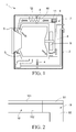
FIG. 1 is a schematic structural view of a laundry washer-dryer; -
FIG. 2 is a schematic partial view of an air heating part and a blowing part of a laundry dryer; -
FIG. 3A is a schematic structural view of a connection device; -
FIG. 3B is a schematic sectional view of A-A inFIG. 3A ; -
FIG. 4A is a schematic sectional view before a connection device is connected with channels; -
FIG. 4B is a schematic sectional view after a connection device is connected with channels. - As shown in
FIG. 1 , a laundry washer-dryer 1 has acase 2. Anouter cylinder 3 ortub 3 is suspended in thecase 2 through adamping device 4. Aninner cylinder 5 ordrum 5 is located in theouter cylinder 3 and is rotatable under driving of amotor 6. A number of through holes (not shown in the drawing) are distributed on theinner cylinder 5, and then theinner cylinder 5 is in communication with theouter cylinder 3 spatially. The head and the tail of anair flow channel 7 are respectively connected with theouter cylinder 3, and then theair flow channel 7 forms an air circulation flow system together with theouter cylinder 3. Along a air flow direction, theair flow channel 7 sequentially includes acondensation part 8, a blowingpart 9, and anair heating part 10 which are connected with one another and spatially communicate with one another. The blowingpart 9 is provided with afan 11 that promotes air flow, and theair heating part 10 is provided with a heater 12 that heats the air. - The air enters the
outer cylinder 3 and theinner cylinder 5 under promotion of thefan 11 after being heated in theair heating part 10 by the heater 12. The hot air takes away part of moisture by contacting wet laundry in theinner cylinder 5, and then enters thecondensation part 8 connected with theouter cylinder 3. In thecondensation part 8, the temperature of the wet hot air decreases, and the moisture in the air is separated from the air. The air from which the moisture is separated re-enters theair heating part 10 under driving of thefan 11, which is repeated so over and over again, to gradually dry the laundry in theinner cylinder 5. - It can be seen from
FIG. 2 that, theair heating part 10 includes an air heatingpart cover plate 101 and an airheating part pedestal 102, the blowingpart 9 includes a blowingpart cover plate 91 and a blowingpart pedestal 92. A cross-shaped seam is formed at a connection place of the air heatingpart cover plate 101, the airheating part pedestal 102, the blowingpart cover plate 91, and the blowingpart pedestal 92. - As shown in
FIGS. 3A, 3B, 4A, and 4B , aconnection device 15 including afirst hoop 13 and asecond hoop 14 is illustrated. Thefirst hoop 13 is hung above a connection place of the air heatingpart cover plate 101 and the blowingpart cover plate 91, thesecond hoop 14 is lying below a connection place of the airheating part pedestal 102 and the blowingpart pedestal 92. Two ends of thefirst hoop 13 and thesecond hoop 14 are fixed respectively throughscrews 16 and thefirst hoop 13 and thesecond hoop 14 tightly compress each other, so as to connect and tightly compress the air heatingpart cover plate 101, the airheating part pedestal 102, the blowingpart cover plate 91, and the blowingpart pedestal 92. - The
first hoop 13 includes afirst slot 17, thesecond hoop 14 includes asecond slot 18, and thefirst slot 17 and thesecond slot 18 respectively haveside walls part cover plate 101 close to the blowingpart cover plate 91 has afirst flange 103, an end portion of the blowingpart cover plate 91 close to the air heatingpart cover plate 101 has asecond flange 93, and thefirst flange 103 and thesecond flange 93 are both accommodated in thefirst slot 17. An end portion of the airheating part pedestal 102 close to the blowingpart pedestal 92 has athird flange 104, an end portion of the blowingpart pedestal 92 close to the airheating part pedestal 102 has afourth flange 94, and thethird flange 104 and thefourth flange 94 are both accommodated in thesecond slot 18. - A side, with the back to the
second flange 93, of thefirst flange 103 has afirst slope 105, a side, with the back to thefirst flange 103, of thesecond flange 93 has asecond slope 106, and thefirst slope 105 and thesecond slope 106 are gradually drawn together from the air heatingpart cover plate 101 and the blowingpart cover plate 91 to the outside. An inclination of theside wall 171 of the first slot corresponds to thefirst slope 105 and thesecond slope 106, so that theside wall 171 of the first slot fits with thefirst slope 105 and thesecond slope 106. - Correspondingly, a side, with the back to the
fourth flange 94, of thethird flange 104 has athird slope 107, a side, with the back to thethird flange 104, of thefourth flange 94 has afourth slope 108, and thethird slope 107 and thefourth slope 108 are gradually drawn together from the airheating part pedestal 102 and the blowingpart pedestal 92 to the outside. An inclination of theside wall 181 of the second slot corresponds to thethird slope 107 and thefourth slope 108, so that theside wall 181 of the second slot fits with thethird slope 107 and thefourth slope 108. - As the
first hoop 13 and thesecond hoop 14 tightly compress each other, the air heatingpart cover plate 101 and the airheating part pedestal 102 tightly compress each other, and the blowingpart cover plate 91 and the blowingpart pedestal 92 tightly compress each other. Meanwhile, due to extrusion of theinclined side wall 171 of thefirst slot 17 and theside wall 181 of thesecond slot 18 on theflanges part cover plate 101 and the blowingpart cover plate 91 tightly compress each other, and the airheating part pedestal 102 and the blowingpart pedestal 92 tightly compress each other. - Various specific embodiments described above and shown in the accompanying drawings are merely used for describing the present invention, instead of being all of the present invention. In the scope of the basic technical idea of the present invention, variations in any forms made by persons of ordinary skill in the related art with respect to the present invention should fall within the protection scope of the present invention.
Claims (7)
- A laundry processor (1) having a pipeline connection device (15), wherein a pipeline (9, 10) comprises a first pipeline wall (101) and a second pipeline wall (91) joined to each other along a pipeline extending direction, and a third pipeline wall (102) joined to the first pipeline wall (101) and vertical to the pipeline extending direction, characterized in that: the connection device (15) comprises a first hoop (13) and a second hoop (14) spanning an outer wall of the pipeline (9, 10) and connected to each other to tightly compress the wall of the pipeline (9, 10), the first hoop (13) comprises a first slot (17), an end portion of the first pipeline wall (101) close to the second pipeline wall (91) has a first flange (103), and an end portion of the second pipeline wall (91) close to the first pipeline wall (101) has a second flange (93), and the first flange (103) and the second flange (93) are both accommodated in the first slot (17).
- The laundry processor (1) according to claim 1, characterized in that a side, with the back to the second flange (93), of the first flange (103) has a first slope (105); a side, with the back to the first flange (103), of the second flange (93) has a second slope (106); and the first slope (105) and the second slope (106) are gradually drawn together from the first pipeline wall (101) and the second pipeline wall (91) to the outside.
- The laundry processor (1) according to claim 2, characterized in that the first slot (17) has a side wall (171) tilted from inside to outside.
- The laundry processor (1) according to claim 3, characterized in that an inclination of the side wall (171) of the first slot corresponds to the first slope (105) and the second slope (106), so that the side wall (171) of the first slot fits with the first slope (105) and the second slope (106).
- The laundry processor (1) according to claim 1, characterized in that: the pipeline (9, 10) further comprises a fourth pipeline wall (92) joined to the third pipeline wall (102) along the pipeline extending direction and joined to the second pipeline wall (91) along a direction vertical to the pipeline extending direction; the second hoop (14) comprises a second slot (18), an end portion of the third pipeline wall (102) close to the fourth pipeline wall (92) has a third flange (104); an end portion of the fourth pipeline wall (92) close to the third pipeline wall (102) has a fourth flange (94); and the third flange (104) and the fourth flange (94) are both accommodated in the second slot (18).
- The laundry processor (1) according to any one of claims 1 to 5, characterized in that: the pipeline (9, 10) is an air flow pipeline.
- The laundry processor (1) according to claim 6, characterized in that: the first pipeline wall (101) and the third pipeline wall (102) form an air heating part (10), and the second pipeline wall (91) and the fourth pipeline wall (92) form a blowing part (9).
Applications Claiming Priority (1)
| Application Number | Priority Date | Filing Date | Title |
|---|---|---|---|
| CN2012206313311U CN202989612U (en) | 2012-11-21 | 2012-11-21 | Clothing treatment machine with pipeline connection device |
Publications (2)
| Publication Number | Publication Date |
|---|---|
| EP2735638A1 true EP2735638A1 (en) | 2014-05-28 |
| EP2735638B1 EP2735638B1 (en) | 2016-07-06 |
Family
ID=48560807
Family Applications (1)
| Application Number | Title | Priority Date | Filing Date |
|---|---|---|---|
| EP13190716.4A Not-in-force EP2735638B1 (en) | 2012-11-21 | 2013-10-29 | Laundry processor having pipeline connection device |
Country Status (3)
| Country | Link |
|---|---|
| EP (1) | EP2735638B1 (en) |
| CN (1) | CN202989612U (en) |
| PL (1) | PL2735638T3 (en) |
Citations (4)
| Publication number | Priority date | Publication date | Assignee | Title |
|---|---|---|---|---|
| US5015018A (en) * | 1988-06-10 | 1991-05-14 | Ductmate Industries, Inc. | Duct connector |
| WO2000011924A1 (en) * | 1998-08-28 | 2000-03-09 | Milnes Pty. Limited | Pipe clamp |
| US20050184524A1 (en) * | 2004-02-23 | 2005-08-25 | Stravitz David M. | Quick-connect/quick-disconnect conduit connectors |
| US20130125410A1 (en) * | 2011-11-22 | 2013-05-23 | ADR Products, LLC | Lint Catching System |
-
2012
- 2012-11-21 CN CN2012206313311U patent/CN202989612U/en not_active Expired - Lifetime
-
2013
- 2013-10-29 PL PL13190716.4T patent/PL2735638T3/en unknown
- 2013-10-29 EP EP13190716.4A patent/EP2735638B1/en not_active Not-in-force
Patent Citations (4)
| Publication number | Priority date | Publication date | Assignee | Title |
|---|---|---|---|---|
| US5015018A (en) * | 1988-06-10 | 1991-05-14 | Ductmate Industries, Inc. | Duct connector |
| WO2000011924A1 (en) * | 1998-08-28 | 2000-03-09 | Milnes Pty. Limited | Pipe clamp |
| US20050184524A1 (en) * | 2004-02-23 | 2005-08-25 | Stravitz David M. | Quick-connect/quick-disconnect conduit connectors |
| US20130125410A1 (en) * | 2011-11-22 | 2013-05-23 | ADR Products, LLC | Lint Catching System |
Also Published As
| Publication number | Publication date |
|---|---|
| PL2735638T3 (en) | 2016-11-30 |
| CN202989612U (en) | 2013-06-12 |
| EP2735638B1 (en) | 2016-07-06 |
Similar Documents
| Publication | Publication Date | Title |
|---|---|---|
| US9845567B2 (en) | Laundry drying machine | |
| CN102373611A (en) | Rotary-drum laundry dryer | |
| CN105793483A (en) | clothes dryer | |
| EP2527526B1 (en) | Rotary-drum laundry dryer | |
| EP2592184A1 (en) | Rotary-drum laundry dryer | |
| CN106968090B (en) | clothes dryer | |
| EP2631353B1 (en) | Rotary-drum laundry dryer | |
| EP2843111B1 (en) | Laundry drying machine | |
| EP2735638B1 (en) | Laundry processor having pipeline connection device | |
| CN207197143U (en) | Stoving rack can tuning cotton-wadded quilt dryer | |
| CN110878468A (en) | Clothing care equipment, control method of clothing care equipment | |
| CN110403326A (en) | A kind of hair dryer | |
| CN210797004U (en) | laundry treatment equipment | |
| CN216474098U (en) | Drying device and drying equipment | |
| CN208136554U (en) | A kind of drying box | |
| EP2631356A1 (en) | Rotary-drum laundry dryer | |
| CN205077290U (en) | Clothes dryer | |
| EP2631357B1 (en) | Rotary-drum laundry dryer | |
| CN217324664U (en) | Clothes drying equipment | |
| EP2735636B1 (en) | Laundry processor having a first pipeline and a second pipeline | |
| CN110878472A (en) | Clothes support, clothes support assembly and clothes care equipment | |
| CN105970583B (en) | Clothes-drying | |
| CN110904654A (en) | Control method for clothes dryer and clothes dryer | |
| CN116411444A (en) | Drying equipment and drying method | |
| CN207878127U (en) | Cabinet type clothes dryer |
Legal Events
| Date | Code | Title | Description |
|---|---|---|---|
| PUAI | Public reference made under article 153(3) epc to a published international application that has entered the european phase |
Free format text: ORIGINAL CODE: 0009012 |
|
| 17P | Request for examination filed |
Effective date: 20131029 |
|
| AK | Designated contracting states |
Kind code of ref document: A1 Designated state(s): AL AT BE BG CH CY CZ DE DK EE ES FI FR GB GR HR HU IE IS IT LI LT LU LV MC MK MT NL NO PL PT RO RS SE SI SK SM TR |
|
| AX | Request for extension of the european patent |
Extension state: BA ME |
|
| R17P | Request for examination filed (corrected) |
Effective date: 20141128 |
|
| RBV | Designated contracting states (corrected) |
Designated state(s): AL AT BE BG CH CY CZ DE DK EE ES FI FR GB GR HR HU IE IS IT LI LT LU LV MC MK MT NL NO PL PT RO RS SE SI SK SM TR |
|
| RAP1 | Party data changed (applicant data changed or rights of an application transferred) |
Owner name: BSH HAUSGERAETE GMBH |
|
| 17Q | First examination report despatched |
Effective date: 20150707 |
|
| GRAP | Despatch of communication of intention to grant a patent |
Free format text: ORIGINAL CODE: EPIDOSNIGR1 |
|
| RIC1 | Information provided on ipc code assigned before grant |
Ipc: F16L 23/08 20060101ALI20160205BHEP Ipc: D06F 58/20 20060101AFI20160205BHEP |
|
| INTG | Intention to grant announced |
Effective date: 20160226 |
|
| GRAS | Grant fee paid |
Free format text: ORIGINAL CODE: EPIDOSNIGR3 |
|
| GRAA | (expected) grant |
Free format text: ORIGINAL CODE: 0009210 |
|
| AK | Designated contracting states |
Kind code of ref document: B1 Designated state(s): AL AT BE BG CH CY CZ DE DK EE ES FI FR GB GR HR HU IE IS IT LI LT LU LV MC MK MT NL NO PL PT RO RS SE SI SK SM TR |
|
| REG | Reference to a national code |
Ref country code: GB Ref legal event code: FG4D |
|
| REG | Reference to a national code |
Ref country code: AT Ref legal event code: REF Ref document number: 810795 Country of ref document: AT Kind code of ref document: T Effective date: 20160715 Ref country code: CH Ref legal event code: EP |
|
| REG | Reference to a national code |
Ref country code: IE Ref legal event code: FG4D |
|
| REG | Reference to a national code |
Ref country code: DE Ref legal event code: R096 Ref document number: 602013009083 Country of ref document: DE |
|
| REG | Reference to a national code |
Ref country code: NL Ref legal event code: MP Effective date: 20160706 |
|
| REG | Reference to a national code |
Ref country code: LT Ref legal event code: MG4D |
|
| REG | Reference to a national code |
Ref country code: AT Ref legal event code: MK05 Ref document number: 810795 Country of ref document: AT Kind code of ref document: T Effective date: 20160706 |
|
| PG25 | Lapsed in a contracting state [announced via postgrant information from national office to epo] |
Ref country code: NO Free format text: LAPSE BECAUSE OF FAILURE TO SUBMIT A TRANSLATION OF THE DESCRIPTION OR TO PAY THE FEE WITHIN THE PRESCRIBED TIME-LIMIT Effective date: 20161006 Ref country code: IT Free format text: LAPSE BECAUSE OF FAILURE TO SUBMIT A TRANSLATION OF THE DESCRIPTION OR TO PAY THE FEE WITHIN THE PRESCRIBED TIME-LIMIT Effective date: 20160706 Ref country code: LT Free format text: LAPSE BECAUSE OF FAILURE TO SUBMIT A TRANSLATION OF THE DESCRIPTION OR TO PAY THE FEE WITHIN THE PRESCRIBED TIME-LIMIT Effective date: 20160706 Ref country code: IS Free format text: LAPSE BECAUSE OF FAILURE TO SUBMIT A TRANSLATION OF THE DESCRIPTION OR TO PAY THE FEE WITHIN THE PRESCRIBED TIME-LIMIT Effective date: 20161106 Ref country code: FI Free format text: LAPSE BECAUSE OF FAILURE TO SUBMIT A TRANSLATION OF THE DESCRIPTION OR TO PAY THE FEE WITHIN THE PRESCRIBED TIME-LIMIT Effective date: 20160706 Ref country code: RS Free format text: LAPSE BECAUSE OF FAILURE TO SUBMIT A TRANSLATION OF THE DESCRIPTION OR TO PAY THE FEE WITHIN THE PRESCRIBED TIME-LIMIT Effective date: 20160706 Ref country code: HR Free format text: LAPSE BECAUSE OF FAILURE TO SUBMIT A TRANSLATION OF THE DESCRIPTION OR TO PAY THE FEE WITHIN THE PRESCRIBED TIME-LIMIT Effective date: 20160706 Ref country code: NL Free format text: LAPSE BECAUSE OF FAILURE TO SUBMIT A TRANSLATION OF THE DESCRIPTION OR TO PAY THE FEE WITHIN THE PRESCRIBED TIME-LIMIT Effective date: 20160706 |
|
| PG25 | Lapsed in a contracting state [announced via postgrant information from national office to epo] |
Ref country code: LV Free format text: LAPSE BECAUSE OF FAILURE TO SUBMIT A TRANSLATION OF THE DESCRIPTION OR TO PAY THE FEE WITHIN THE PRESCRIBED TIME-LIMIT Effective date: 20160706 Ref country code: SE Free format text: LAPSE BECAUSE OF FAILURE TO SUBMIT A TRANSLATION OF THE DESCRIPTION OR TO PAY THE FEE WITHIN THE PRESCRIBED TIME-LIMIT Effective date: 20160706 Ref country code: BE Free format text: LAPSE BECAUSE OF NON-PAYMENT OF DUE FEES Effective date: 20160706 Ref country code: AT Free format text: LAPSE BECAUSE OF FAILURE TO SUBMIT A TRANSLATION OF THE DESCRIPTION OR TO PAY THE FEE WITHIN THE PRESCRIBED TIME-LIMIT Effective date: 20160706 Ref country code: GR Free format text: LAPSE BECAUSE OF FAILURE TO SUBMIT A TRANSLATION OF THE DESCRIPTION OR TO PAY THE FEE WITHIN THE PRESCRIBED TIME-LIMIT Effective date: 20161007 Ref country code: ES Free format text: LAPSE BECAUSE OF FAILURE TO SUBMIT A TRANSLATION OF THE DESCRIPTION OR TO PAY THE FEE WITHIN THE PRESCRIBED TIME-LIMIT Effective date: 20160706 Ref country code: PT Free format text: LAPSE BECAUSE OF FAILURE TO SUBMIT A TRANSLATION OF THE DESCRIPTION OR TO PAY THE FEE WITHIN THE PRESCRIBED TIME-LIMIT Effective date: 20161107 |
|
| REG | Reference to a national code |
Ref country code: DE Ref legal event code: R097 Ref document number: 602013009083 Country of ref document: DE |
|
| PG25 | Lapsed in a contracting state [announced via postgrant information from national office to epo] |
Ref country code: RO Free format text: LAPSE BECAUSE OF FAILURE TO SUBMIT A TRANSLATION OF THE DESCRIPTION OR TO PAY THE FEE WITHIN THE PRESCRIBED TIME-LIMIT Effective date: 20160706 Ref country code: EE Free format text: LAPSE BECAUSE OF FAILURE TO SUBMIT A TRANSLATION OF THE DESCRIPTION OR TO PAY THE FEE WITHIN THE PRESCRIBED TIME-LIMIT Effective date: 20160706 |
|
| PLBE | No opposition filed within time limit |
Free format text: ORIGINAL CODE: 0009261 |
|
| STAA | Information on the status of an ep patent application or granted ep patent |
Free format text: STATUS: NO OPPOSITION FILED WITHIN TIME LIMIT |
|
| PG25 | Lapsed in a contracting state [announced via postgrant information from national office to epo] |
Ref country code: SK Free format text: LAPSE BECAUSE OF FAILURE TO SUBMIT A TRANSLATION OF THE DESCRIPTION OR TO PAY THE FEE WITHIN THE PRESCRIBED TIME-LIMIT Effective date: 20160706 Ref country code: CZ Free format text: LAPSE BECAUSE OF FAILURE TO SUBMIT A TRANSLATION OF THE DESCRIPTION OR TO PAY THE FEE WITHIN THE PRESCRIBED TIME-LIMIT Effective date: 20160706 Ref country code: SM Free format text: LAPSE BECAUSE OF FAILURE TO SUBMIT A TRANSLATION OF THE DESCRIPTION OR TO PAY THE FEE WITHIN THE PRESCRIBED TIME-LIMIT Effective date: 20160706 Ref country code: BG Free format text: LAPSE BECAUSE OF FAILURE TO SUBMIT A TRANSLATION OF THE DESCRIPTION OR TO PAY THE FEE WITHIN THE PRESCRIBED TIME-LIMIT Effective date: 20161006 Ref country code: DK Free format text: LAPSE BECAUSE OF FAILURE TO SUBMIT A TRANSLATION OF THE DESCRIPTION OR TO PAY THE FEE WITHIN THE PRESCRIBED TIME-LIMIT Effective date: 20160706 |
|
| REG | Reference to a national code |
Ref country code: CH Ref legal event code: PL |
|
| 26N | No opposition filed |
Effective date: 20170407 |
|
| REG | Reference to a national code |
Ref country code: IE Ref legal event code: MM4A |
|
| REG | Reference to a national code |
Ref country code: FR Ref legal event code: ST Effective date: 20170630 |
|
| PG25 | Lapsed in a contracting state [announced via postgrant information from national office to epo] |
Ref country code: CH Free format text: LAPSE BECAUSE OF NON-PAYMENT OF DUE FEES Effective date: 20161031 Ref country code: FR Free format text: LAPSE BECAUSE OF NON-PAYMENT OF DUE FEES Effective date: 20161102 Ref country code: LI Free format text: LAPSE BECAUSE OF NON-PAYMENT OF DUE FEES Effective date: 20161031 |
|
| PG25 | Lapsed in a contracting state [announced via postgrant information from national office to epo] |
Ref country code: LU Free format text: LAPSE BECAUSE OF NON-PAYMENT OF DUE FEES Effective date: 20161029 Ref country code: SI Free format text: LAPSE BECAUSE OF FAILURE TO SUBMIT A TRANSLATION OF THE DESCRIPTION OR TO PAY THE FEE WITHIN THE PRESCRIBED TIME-LIMIT Effective date: 20160706 |
|
| PG25 | Lapsed in a contracting state [announced via postgrant information from national office to epo] |
Ref country code: IE Free format text: LAPSE BECAUSE OF NON-PAYMENT OF DUE FEES Effective date: 20161029 |
|
| PG25 | Lapsed in a contracting state [announced via postgrant information from national office to epo] |
Ref country code: HU Free format text: LAPSE BECAUSE OF FAILURE TO SUBMIT A TRANSLATION OF THE DESCRIPTION OR TO PAY THE FEE WITHIN THE PRESCRIBED TIME-LIMIT; INVALID AB INITIO Effective date: 20131029 Ref country code: CY Free format text: LAPSE BECAUSE OF FAILURE TO SUBMIT A TRANSLATION OF THE DESCRIPTION OR TO PAY THE FEE WITHIN THE PRESCRIBED TIME-LIMIT Effective date: 20160706 |
|
| PG25 | Lapsed in a contracting state [announced via postgrant information from national office to epo] |
Ref country code: MT Free format text: LAPSE BECAUSE OF NON-PAYMENT OF DUE FEES Effective date: 20161031 Ref country code: MK Free format text: LAPSE BECAUSE OF FAILURE TO SUBMIT A TRANSLATION OF THE DESCRIPTION OR TO PAY THE FEE WITHIN THE PRESCRIBED TIME-LIMIT Effective date: 20160706 Ref country code: MC Free format text: LAPSE BECAUSE OF FAILURE TO SUBMIT A TRANSLATION OF THE DESCRIPTION OR TO PAY THE FEE WITHIN THE PRESCRIBED TIME-LIMIT Effective date: 20160706 |
|
| PG25 | Lapsed in a contracting state [announced via postgrant information from national office to epo] |
Ref country code: TR Free format text: LAPSE BECAUSE OF FAILURE TO SUBMIT A TRANSLATION OF THE DESCRIPTION OR TO PAY THE FEE WITHIN THE PRESCRIBED TIME-LIMIT Effective date: 20160706 Ref country code: AL Free format text: LAPSE BECAUSE OF FAILURE TO SUBMIT A TRANSLATION OF THE DESCRIPTION OR TO PAY THE FEE WITHIN THE PRESCRIBED TIME-LIMIT Effective date: 20160706 |
|
| PGFP | Annual fee paid to national office [announced via postgrant information from national office to epo] |
Ref country code: PL Payment date: 20181022 Year of fee payment: 6 |
|
| REG | Reference to a national code |
Ref country code: DE Ref legal event code: R084 Ref document number: 602013009083 Country of ref document: DE |
|
| PGFP | Annual fee paid to national office [announced via postgrant information from national office to epo] |
Ref country code: GB Payment date: 20191023 Year of fee payment: 7 |
|
| GBPC | Gb: european patent ceased through non-payment of renewal fee |
Effective date: 20201029 |
|
| PG25 | Lapsed in a contracting state [announced via postgrant information from national office to epo] |
Ref country code: GB Free format text: LAPSE BECAUSE OF NON-PAYMENT OF DUE FEES Effective date: 20201029 |
|
| PG25 | Lapsed in a contracting state [announced via postgrant information from national office to epo] |
Ref country code: PL Free format text: LAPSE BECAUSE OF NON-PAYMENT OF DUE FEES Effective date: 20191029 |
|
| PGFP | Annual fee paid to national office [announced via postgrant information from national office to epo] |
Ref country code: DE Payment date: 20231031 Year of fee payment: 11 |
|
| REG | Reference to a national code |
Ref country code: DE Ref legal event code: R119 Ref document number: 602013009083 Country of ref document: DE |
|
| PG25 | Lapsed in a contracting state [announced via postgrant information from national office to epo] |
Ref country code: DE Free format text: LAPSE BECAUSE OF NON-PAYMENT OF DUE FEES Effective date: 20250501 |