EP2735636A2 - Laundry processor having a first pipeline and a second pipeline - Google Patents
Laundry processor having a first pipeline and a second pipeline Download PDFInfo
- Publication number
- EP2735636A2 EP2735636A2 EP13191417.8A EP13191417A EP2735636A2 EP 2735636 A2 EP2735636 A2 EP 2735636A2 EP 13191417 A EP13191417 A EP 13191417A EP 2735636 A2 EP2735636 A2 EP 2735636A2
- Authority
- EP
- European Patent Office
- Prior art keywords
- pipeline
- sealing strip
- channel
- wall
- pipeline wall
- Prior art date
- Legal status (The legal status is an assumption and is not a legal conclusion. Google has not performed a legal analysis and makes no representation as to the accuracy of the status listed.)
- Granted
Links
Images

Classifications
-
- D—TEXTILES; PAPER
- D06—TREATMENT OF TEXTILES OR THE LIKE; LAUNDERING; FLEXIBLE MATERIALS NOT OTHERWISE PROVIDED FOR
- D06F—LAUNDERING, DRYING, IRONING, PRESSING OR FOLDING TEXTILE ARTICLES
- D06F58/00—Domestic laundry dryers
- D06F58/20—General details of domestic laundry dryers
Definitions
- the present invention relates to a laundry processor especially clothes dryer or washing machine having a first pipeline and a second pipeline, wherein the first pipeline and the second pipeline are connected to each other and communicate with each other spatially;
- the first pipeline comprises a first pipeline wall and a second pipeline wall;
- a first sealing strip is disposed between the first pipeline wall and the second pipeline wall;
- the second pipeline comprises a third pipeline wall and a fourth pipeline wall;
- a second sealing strip is disposed between the third pipeline wall and the fourth pipeline wall.
- the relatively common one includes an air circulation channel.
- the air circulation channel includes a drying channel that heats the air, a fan channel that facilitates the air to flow in the circulation channel, and a condensation channel that condensates wet hot air from the clothes drying drum.
- the air is forced into the clothes drying drum by a fan in the fan channel after being heated in the drying channel by a heating device, and the hot air takes away part of moisture after contacting wet clothes in the drum, and then enters the condensation channel connected to the drum.
- the moisture in the air is separated from the air in the condensation channel.
- the air from which the moisture is separated re-enters the drying channel under driving of the fan, which is repeated so over and over again, to gradually dry the clothes in the drum.
- the thermal efficiency of the heating device in the drying channel is directly related to energy consumption and the drying speed of the clothes dryer. Therefore, the sealing performance of the drying channel is often very important. Meanwhile, as the fan channel is directly connected to the drying channel, its sealing performance is equally important.
- the drying channel consists of a drying channel cover plate and a drying channel pedestal
- the fan channel consists of a fan room cover plate and a fan room pedestal
- the four means are jointed to one another.
- the joint place is a staggered structure, it is relatively difficult to set a solid seal ring; in order to seal the joint place, the current practice is to dispose a rubber seal ring between the drying channel cover plate and the drying channel pedestal as well as the fan channel cover plate and the fan channel pedestal, but a liquid sealant is used between the drying channel and the fan channel to achieve seal.
- sealant requires a special coating device, resulting in poor assembly accuracy and consistency.
- the sealant needs to take time to achieve curing. Besides, as the drying channel is usually in high-temperature environments, the sealant easily gives off unhealthy gases.
- One objective of the present invention is to provide a further development of the state of the art.
- One objective of the present invention is to avoid using a liquid sealant in a circulation channel of a laundry processor.
- a laundry processor having a first pipeline and a second pipeline, wherein the first pipeline and the second pipeline are connected to each other and communicate with each other spatially;
- the first pipeline comprises a first pipeline wall and a second pipeline wall;
- a first sealing strip is disposed between the first pipeline wall and the second pipeline wall;
- the second pipeline comprises a third pipeline wall and a fourth pipeline wall;
- a second sealing strip is disposed between the third pipeline wall and the fourth pipeline wall, characterized in that: a third sealing strip is disposed at a connection place of the first pipeline and the second pipeline, and end portions of the first sealing strip and the second sealing strip connect the third sealing strip.
- grooves for accommodating the end portions of the first sealing strip and the second sealing strip are disposed on the third sealing strip.
- the groove of the third sealing strip has a tilted side wall opening in a trumpet shape from inside to outside, and end portions of the first sealing strip and the second sealing strip each have a mounting portion in a shape corresponding to that of the groove, so that the end portions coincide with the grooves.
- the mounting portions respectively go beyond a connection face of the first pipeline and opposite to the second pipeline.
- first sealing strip and the second sealing strip are located on an extending line of each other.
- the pipeline is an air flow pipeline.
- first pipeline wall and the second pipeline wall form an air heating channel including a heater
- third pipeline wall and the fourth pipeline wall form a blowing channel including a fan
- the laundry processor is a clothes dryer or a washing machine
- the first pipeline includes a drying channel
- the second pipeline includes a blowing channel
- the present invention does not use a liquid sealant between the drying channel and the fan channel of the clothes dryer, which thus avoids the shortcomings in the prior art, has good sealing effects between respective means of the drying channel and the fan channel, and also improves assembly stability and accuracy.
- the present invention is not only applicable to the clothes dryer, but also applicable to any other appropriate laundry processing devices such as washing machine. Moreover, the present invention is not only applicable to connection between the air heating channel and the blowing channel, but also applicable to various other appropriate channels in the laundry processing device.
- a clothes dryer 1 has a case 2.
- An outer drum 3 is suspended in the case 2 through a damping device 4.
- An inner drum 5 is located in the outer drum 3 and is rotatable under driving of a motor 6.
- a number of through holes are distributed on the inner drum 5, and then the inner drum 5 is in communication with the outer drum 3 spatially.
- the head and the tail of an air flow channel 7 are respectively connected to the outer drum 3, and then the air flow channel 7 forms an air circulation flow system together with the outer drum 3.
- the air flow channel 7 sequentially includes a condensation channel 8, a fan channel 9, and a drying channel 10 which are connected to one another and spatially communicate with one another.
- the fan channel 9 is provided with a fan 11 that promotes air circulation
- the drying channel 10 is provided with a heater 12 that heats the air.
- the air enters the outer drum 3 and the inner drum 5 under promotion of the fan 11 after being heated by the heater 12.
- the hot air takes away part of moisture after contacting wet clothes in the inner drum 5, and then enters the condensation channel 8 connected to the outer drum 3.
- the condensation channel 8 the temperature of the wet hot air decreases, and the moisture in the air is separated from the air.
- the air from which the moisture is separated re-enters the drying channel 10 under driving of the fan 11, which is repeated so over and over again, to gradually dry the clothes in the inner drum 5.
- the drying channel 10 includes a drying channel cover plate 101 and a drying channel pedestal 102
- the fan channel 9 includes a fan channel cover plate 91 and a fan channel pedestal 92.
- the first pipeline can be or includes the drying channel 10
- the first pipeline wall can be the drying channel cover plate 101 and the second pipeline wall can be the drying channel pedestal 102.
- the second pipeline can be or includes the fan channel 9
- the third pipeline wall can be the fan channel cover plate 91 and the fourth pipeline wall can be the fan channel pedestal 92.
- a cross-shaped seam is formed at a connection place of the drying channel cover plate 101, the drying channel pedestal 102, the fan channel cover plate 91, and the fan channel pedestal 92. As shown in FIG. 3 and FIG.
- a first sealing strip 13a is disposed between the drying channel cover plate 101 and the drying channel pedestal 102
- a second sealing strip 13b is disposed between the fan channel cover plate 91 and the fan channel pedestal 92
- a third sealing strip 13c is disposed at a connection place of the drying channel 10 and the fan channel 9.
- grooves 16, 17 are respectively disposed at positions, corresponding to an end portion 14 of the first sealing strip 13a and an end portion 15 of the second sealing strip 13b, on the third sealing strip 13c, and the grooves 16, 17 respectively have tilted side walls 18 opening in a trumpet shape from inside to outside.
- the end portion 14 of the first sealing strip 13a and the end portion 15 of the second sealing strip 13b respectively have mounting portions 19a, 19b in a shape corresponding to that of the grooves 16, 17, so that the end portions coincide with the grooves.
- the mounting portions 19a, 19b respectively go beyond connection faces 10a, 9a of the drying channel and opposite to the fan room, fall into the grooves 16, 17 on the third sealing strip 13c upon mounting, and tightly compress the third sealing strip 13c along extending directions of the first sealing strip 13a and the second sealing strip 13b respectively.
- the first sealing strip 13a and the second sealing strip 13b are located on an extending line of each other.
Landscapes
- Engineering & Computer Science (AREA)
- Textile Engineering (AREA)
- Detail Structures Of Washing Machines And Dryers (AREA)
Abstract
Description
- The present invention relates to a laundry processor especially clothes dryer or washing machine having a first pipeline and a second pipeline, wherein the first pipeline and the second pipeline are connected to each other and communicate with each other spatially; the first pipeline comprises a first pipeline wall and a second pipeline wall; a first sealing strip is disposed between the first pipeline wall and the second pipeline wall; the second pipeline comprises a third pipeline wall and a fourth pipeline wall; a second sealing strip is disposed between the third pipeline wall and the fourth pipeline wall.
- In various clothes dryers, the relatively common one includes an air circulation channel. The air circulation channel includes a drying channel that heats the air, a fan channel that facilitates the air to flow in the circulation channel, and a condensation channel that condensates wet hot air from the clothes drying drum. The air is forced into the clothes drying drum by a fan in the fan channel after being heated in the drying channel by a heating device, and the hot air takes away part of moisture after contacting wet clothes in the drum, and then enters the condensation channel connected to the drum. The moisture in the air is separated from the air in the condensation channel. The air from which the moisture is separated re-enters the drying channel under driving of the fan, which is repeated so over and over again, to gradually dry the clothes in the drum.
- The thermal efficiency of the heating device in the drying channel is directly related to energy consumption and the drying speed of the clothes dryer. Therefore, the sealing performance of the drying channel is often very important. Meanwhile, as the fan channel is directly connected to the drying channel, its sealing performance is equally important.
- Currently, a common way of constructing the drying channel and the fan channel is that the drying channel consists of a drying channel cover plate and a drying channel pedestal, the fan channel consists of a fan room cover plate and a fan room pedestal, and the four means are jointed to one another. As the joint place is a staggered structure, it is relatively difficult to set a solid seal ring; in order to seal the joint place, the current practice is to dispose a rubber seal ring between the drying channel cover plate and the drying channel pedestal as well as the fan channel cover plate and the fan channel pedestal, but a liquid sealant is used between the drying channel and the fan channel to achieve seal.
- However, application of the sealant requires a special coating device, resulting in poor assembly accuracy and consistency. The sealant needs to take time to achieve curing. Besides, as the drying channel is usually in high-temperature environments, the sealant easily gives off unhealthy gases.
- It is an objective of the present invention to provide a further development of the state of the art. One objective of the present invention is to avoid using a liquid sealant in a circulation channel of a laundry processor.
- This objective is solved by a laundry processor according to claim1.
- According to the invention a laundry processor having a first pipeline and a second pipeline, wherein the first pipeline and the second pipeline are connected to each other and communicate with each other spatially; the first pipeline comprises a first pipeline wall and a second pipeline wall; a first sealing strip is disposed between the first pipeline wall and the second pipeline wall; the second pipeline comprises a third pipeline wall and a fourth pipeline wall; a second sealing strip is disposed between the third pipeline wall and the fourth pipeline wall, characterized in that: a third sealing strip is disposed at a connection place of the first pipeline and the second pipeline, and end portions of the first sealing strip and the second sealing strip connect the third sealing strip.
- In a preferred embodiment, it is provided that grooves for accommodating the end portions of the first sealing strip and the second sealing strip are disposed on the third sealing strip.
- In a further preferred embodiment, it is provided that the groove of the third sealing strip has a tilted side wall opening in a trumpet shape from inside to outside, and end portions of the first sealing strip and the second sealing strip each have a mounting portion in a shape corresponding to that of the groove, so that the end portions coincide with the grooves.
- In a further preferred embodiment, it is provided that the mounting portions respectively go beyond a connection face of the first pipeline and opposite to the second pipeline.
- In a further preferred embodiment, it is provided that the first sealing strip and the second sealing strip are located on an extending line of each other.
- In a further preferred embodiment, it is provided that the pipeline is an air flow pipeline.
- In a further preferred embodiment, it is provided that the first pipeline wall and the second pipeline wall form an air heating channel including a heater, and the third pipeline wall and the fourth pipeline wall form a blowing channel including a fan.
- In a further preferred embodiment, it is provided that the laundry processor is a clothes dryer or a washing machine, the first pipeline includes a drying channel and the second pipeline includes a blowing channel.
- Compared with the prior art, the present invention does not use a liquid sealant between the drying channel and the fan channel of the clothes dryer, which thus avoids the shortcomings in the prior art, has good sealing effects between respective means of the drying channel and the fan channel, and also improves assembly stability and accuracy.
- The invention is described in more detail below on the basis of a preferred embodiment by taking a clothes dryer as an example and with reference to the attached drawing. It should be clarified that, the present invention is not only applicable to the clothes dryer, but also applicable to any other appropriate laundry processing devices such as washing machine. Moreover, the present invention is not only applicable to connection between the air heating channel and the blowing channel, but also applicable to various other appropriate channels in the laundry processing device.
-
FIG. 1 is a schematic structural view of a clothes dryer; -
FIG. 2 is a schematic partial view of a drying channel and a fan room of the clothes dryer; -
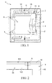
FIG. 3 is a schematic structural view of A inFIG. 2 ; and -
FIG. 4 is an exploded view ofFIG. 3 . - As shown in
FIG. 1 , aclothes dryer 1 has acase 2. Anouter drum 3 is suspended in thecase 2 through adamping device 4. Aninner drum 5 is located in theouter drum 3 and is rotatable under driving of amotor 6. A number of through holes (not shown in the drawing) are distributed on theinner drum 5, and then theinner drum 5 is in communication with theouter drum 3 spatially. The head and the tail of anair flow channel 7 are respectively connected to theouter drum 3, and then theair flow channel 7 forms an air circulation flow system together with theouter drum 3. Along an air flow direction, theair flow channel 7 sequentially includes acondensation channel 8, afan channel 9, and adrying channel 10 which are connected to one another and spatially communicate with one another. Thefan channel 9 is provided with afan 11 that promotes air circulation, and thedrying channel 10 is provided with aheater 12 that heats the air. - The air enters the
outer drum 3 and theinner drum 5 under promotion of thefan 11 after being heated by theheater 12. The hot air takes away part of moisture after contacting wet clothes in theinner drum 5, and then enters thecondensation channel 8 connected to theouter drum 3. In thecondensation channel 8, the temperature of the wet hot air decreases, and the moisture in the air is separated from the air. The air from which the moisture is separated re-enters thedrying channel 10 under driving of thefan 11, which is repeated so over and over again, to gradually dry the clothes in theinner drum 5. - It can be seen from
FIG. 2 that, thedrying channel 10 includes a dryingchannel cover plate 101 and adrying channel pedestal 102, thefan channel 9 includes a fanchannel cover plate 91 and afan channel pedestal 92. The first pipeline can be or includes thedrying channel 10, the first pipeline wall can be the dryingchannel cover plate 101 and the second pipeline wall can be thedrying channel pedestal 102. The second pipeline can be or includes thefan channel 9, the third pipeline wall can be the fanchannel cover plate 91 and the fourth pipeline wall can be thefan channel pedestal 92. A cross-shaped seam is formed at a connection place of the dryingchannel cover plate 101, thedrying channel pedestal 102, the fanchannel cover plate 91, and thefan channel pedestal 92. As shown inFIG. 3 and FIG. 4 , afirst sealing strip 13a is disposed between the dryingchannel cover plate 101 and thedrying channel pedestal 102, asecond sealing strip 13b is disposed between the fanchannel cover plate 91 and thefan channel pedestal 92, and athird sealing strip 13c is disposed at a connection place of thedrying channel 10 and thefan channel 9. - In order to ensure the sealing between the
third sealing strip 13c and thefirst sealing strip 13a as well as thesecond sealing strip 13b,grooves end portion 14 of thefirst sealing strip 13a and anend portion 15 of thesecond sealing strip 13b, on thethird sealing strip 13c, and thegrooves side walls 18 opening in a trumpet shape from inside to outside. Theend portion 14 of thefirst sealing strip 13a and theend portion 15 of thesecond sealing strip 13b respectively have mountingportions grooves portions grooves third sealing strip 13c upon mounting, and tightly compress thethird sealing strip 13c along extending directions of thefirst sealing strip 13a and thesecond sealing strip 13b respectively. Thefirst sealing strip 13a and thesecond sealing strip 13b are located on an extending line of each other. - Various specific embodiments described above and shown in the accompanying drawings are merely used for describing the present invention, instead of being all of the present invention. In the scope of the basic technical idea of the present invention, variations in any forms made by persons of ordinary skill in the related art with respect to the present invention should fall within the protection scope of the present invention.
-
- 1, clothes dryer
- 2, case
- 3, outer drum
- 4, damping device
- 5, inner drum
- 6, motor
- 7, air flow channel
- 8, condensation channel
- 9, fan channel\the second pipeline
- 91, fan channel cover plate\the third pipeline wall
- 92, fan channel pedestal\the fourth pipeline wall
- 9a, connection face
- 10, drying channel\the first pipeline
- 101, drying channel cover plate\the first pipeline wall
- 102, drying channel pedestal\the second pipeline wall
- 10a, connection face
- 11, fan
- 12, heater
- 13a, the first sealing strip
- 13b, the second sealing strip
- 13c, the third sealing strip
- 14, end portion of the first sealing strip
- 15, end portion of the second sealing strip
- 16, the groove
- 17, the groove
- 18, tilted side wall
- 19a, mounting portion
- 19b, mounting portion
Claims (8)
- A laundry processor having a first pipeline and a second pipeline, wherein the first pipeline (10) and the second pipeline (9) are connected to each other and communicate with each other spatially; the first pipeline (10) comprises a first pipeline wall (101) and a second pipeline wall (102); a first sealing strip (13a) is disposed between the first pipeline wall (101) and the second pipeline wall (102); the second pipeline (9) comprises a third pipeline wall (91) and a fourth pipeline wall (92); a second sealing strip (13b) is disposed between the third pipeline wall (91) and the fourth pipeline wall (92), characterized in that: a third sealing strip (13c) is disposed at a connection place of the first pipeline (10) and the second pipeline (9), and end portions (14, 15) of the first sealing strip (13a) and the second sealing strip (13b) connect the third sealing strip (13c).
- The laundry processor according to claim 1, characterized in that: grooves (16, 17) for accommodating the end portions (14, 15) of the first sealing strip (13a) and the second sealing strip (13b) are disposed on the third sealing strip (13c).
- The laundry processor according to claim 2, characterized in that: the groove (16, 17) of the third sealing strip(13c) has a tilted side wall (16a, 17a) opening in a trumpet shape from inside to outside, and end portions (14, 15) of the first sealing strip (13a) and the second sealing strip (13b) each have a mounting portion (19a, 19b) in a shape corresponding to that of the groove (16, 17), so that the end portions coincide with the grooves.
- The laundry processor according to claim 3, characterized in that: the mounting portions (19a, 19b) respectively go beyond a connection face (10a, 9a) of the first pipeline(10) and opposite to the second pipeline(9).
- The laundry processor according to claim 1, characterized in that: the first sealing strip (13a) and the second sealing strip (13b) are located on an extending line of each other.
- The laundry processor according to any one of claims 1 to 5, characterized in that: the pipeline (9, 10) is an air flow pipeline.
- The laundry processor according to claim 6, characterized in that: the first pipeline wall (101) and the second pipeline wall (102) form an air heating channel (10) including a heater(12), and the third pipeline wall (91) and the fourth pipeline wall (92) form a blowing channel (9) including a fan(11).
- The laundry processor according to any of the preceding claims, characterized in that: the laundry processor (1) is a clothes dryer or a washing machine, the first pipeline (10) includes a drying channel and the second pipeline (9) includes a blowing channel.
Priority Applications (1)
| Application Number | Priority Date | Filing Date | Title |
|---|---|---|---|
| PL13191417T PL2735636T3 (en) | 2012-11-21 | 2013-11-04 | Laundry processor having a first pipeline and a second pipeline |
Applications Claiming Priority (1)
| Application Number | Priority Date | Filing Date | Title |
|---|---|---|---|
| CN2012206313006U CN202989611U (en) | 2012-11-21 | 2012-11-21 | Clothes dryer with drying tunnel and fan chamber |
Publications (3)
| Publication Number | Publication Date |
|---|---|
| EP2735636A2 true EP2735636A2 (en) | 2014-05-28 |
| EP2735636A3 EP2735636A3 (en) | 2018-01-24 |
| EP2735636B1 EP2735636B1 (en) | 2019-06-19 |
Family
ID=48560806
Family Applications (1)
| Application Number | Title | Priority Date | Filing Date |
|---|---|---|---|
| EP13191417.8A Active EP2735636B1 (en) | 2012-11-21 | 2013-11-04 | Laundry processor having a first pipeline and a second pipeline |
Country Status (3)
| Country | Link |
|---|---|
| EP (1) | EP2735636B1 (en) |
| CN (1) | CN202989611U (en) |
| PL (1) | PL2735636T3 (en) |
Family Cites Families (2)
| Publication number | Priority date | Publication date | Assignee | Title |
|---|---|---|---|---|
| JP2005137504A (en) * | 2003-11-05 | 2005-06-02 | Matsushita Electric Ind Co Ltd | Clothes dryer |
| KR20100037450A (en) * | 2008-10-01 | 2010-04-09 | 엘지전자 주식회사 | Laundry treatment machine |
-
2012
- 2012-11-21 CN CN2012206313006U patent/CN202989611U/en not_active Expired - Lifetime
-
2013
- 2013-11-04 EP EP13191417.8A patent/EP2735636B1/en active Active
- 2013-11-04 PL PL13191417T patent/PL2735636T3/en unknown
Non-Patent Citations (1)
| Title |
|---|
| None |
Also Published As
| Publication number | Publication date |
|---|---|
| CN202989611U (en) | 2013-06-12 |
| PL2735636T3 (en) | 2019-12-31 |
| EP2735636A3 (en) | 2018-01-24 |
| EP2735636B1 (en) | 2019-06-19 |
Similar Documents
| Publication | Publication Date | Title |
|---|---|---|
| CN106480685A (en) | A kind of clothes drying method and dryer | |
| CN109023831B (en) | Washing and drying integrated machine | |
| CN222541094U (en) | Clothes processing equipment | |
| EP2735636B1 (en) | Laundry processor having a first pipeline and a second pipeline | |
| CN204138970U (en) | A kind of dryer adopting Far-infrared Heating | |
| CN110100056A (en) | washer dryer | |
| CN107523960A (en) | One kind laundry drying clothes integrated machine and its control method | |
| CN220952602U (en) | Drying system and clothes drying equipment | |
| CN210766046U (en) | Clothes dryer base and clothes dryer | |
| CN210797004U (en) | laundry treatment equipment | |
| CN222541092U (en) | Clothes processing equipment | |
| EP2735638B1 (en) | Laundry processor having pipeline connection device | |
| TR201719688T3 (en) | A HOME APPLIANCE WITH HUMIDIFICATION IN THE DRYING STEP. | |
| CN217324664U (en) | Clothes drying equipment | |
| CN205188659U (en) | Drying washing machine | |
| CN110904654A (en) | Control method for clothes dryer and clothes dryer | |
| JP2015104472A (en) | Washing and drying machine | |
| CN108589165A (en) | Cleaning device and washing machine with same | |
| CN206127696U (en) | Drying hanger | |
| CN210267978U (en) | a dehumidifier | |
| CN107504783B (en) | A kind of drying equipment for glass noodle processing | |
| CN220952608U (en) | Heat exchange module, dehumidification module and clothing washing equipment | |
| CN105780421A (en) | Dehydrating and clothes-drying dual-purpose machine | |
| CN202989613U (en) | Clothes drying system | |
| CN204982472U (en) | Energy -conserving clothesdrier |
Legal Events
| Date | Code | Title | Description |
|---|---|---|---|
| PUAI | Public reference made under article 153(3) epc to a published international application that has entered the european phase |
Free format text: ORIGINAL CODE: 0009012 |
|
| 17P | Request for examination filed |
Effective date: 20131104 |
|
| AK | Designated contracting states |
Kind code of ref document: A2 Designated state(s): AL AT BE BG CH CY CZ DE DK EE ES FI FR GB GR HR HU IE IS IT LI LT LU LV MC MK MT NL NO PL PT RO RS SE SI SK SM TR |
|
| AX | Request for extension of the european patent |
Extension state: BA ME |
|
| RAP1 | Party data changed (applicant data changed or rights of an application transferred) |
Owner name: BSH HAUSGERAETE GMBH |
|
| PUAL | Search report despatched |
Free format text: ORIGINAL CODE: 0009013 |
|
| RIC1 | Information provided on ipc code assigned before grant |
Ipc: D06F 58/20 20060101ALI20171213BHEP Ipc: D06F 58/02 20060101AFI20171213BHEP |
|
| AK | Designated contracting states |
Kind code of ref document: A3 Designated state(s): AL AT BE BG CH CY CZ DE DK EE ES FI FR GB GR HR HU IE IS IT LI LT LU LV MC MK MT NL NO PL PT RO RS SE SI SK SM TR |
|
| AX | Request for extension of the european patent |
Extension state: BA ME |
|
| STAA | Information on the status of an ep patent application or granted ep patent |
Free format text: STATUS: REQUEST FOR EXAMINATION WAS MADE |
|
| R17P | Request for examination filed (corrected) |
Effective date: 20180724 |
|
| RBV | Designated contracting states (corrected) |
Designated state(s): AL AT BE BG CH CY CZ DE DK EE ES FI FR GB GR HR HU IE IS IT LI LT LU LV MC MK MT NL NO PL PT RO RS SE SI SK SM TR |
|
| RIC1 | Information provided on ipc code assigned before grant |
Ipc: D06F 58/20 20060101ALI20181218BHEP Ipc: D06F 58/02 20060101AFI20181218BHEP |
|
| GRAP | Despatch of communication of intention to grant a patent |
Free format text: ORIGINAL CODE: EPIDOSNIGR1 |
|
| STAA | Information on the status of an ep patent application or granted ep patent |
Free format text: STATUS: GRANT OF PATENT IS INTENDED |
|
| INTG | Intention to grant announced |
Effective date: 20190128 |
|
| RIN1 | Information on inventor provided before grant (corrected) |
Inventor name: ZIEGLER, JOERG Inventor name: WANG, YONGJIA |
|
| GRAS | Grant fee paid |
Free format text: ORIGINAL CODE: EPIDOSNIGR3 |
|
| GRAA | (expected) grant |
Free format text: ORIGINAL CODE: 0009210 |
|
| STAA | Information on the status of an ep patent application or granted ep patent |
Free format text: STATUS: THE PATENT HAS BEEN GRANTED |
|
| AK | Designated contracting states |
Kind code of ref document: B1 Designated state(s): AL AT BE BG CH CY CZ DE DK EE ES FI FR GB GR HR HU IE IS IT LI LT LU LV MC MK MT NL NO PL PT RO RS SE SI SK SM TR |
|
| REG | Reference to a national code |
Ref country code: GB Ref legal event code: FG4D |
|
| REG | Reference to a national code |
Ref country code: CH Ref legal event code: EP |
|
| REG | Reference to a national code |
Ref country code: IE Ref legal event code: FG4D |
|
| REG | Reference to a national code |
Ref country code: AT Ref legal event code: REF Ref document number: 1145668 Country of ref document: AT Kind code of ref document: T Effective date: 20190715 |
|
| REG | Reference to a national code |
Ref country code: DE Ref legal event code: R096 Ref document number: 602013056736 Country of ref document: DE |
|
| REG | Reference to a national code |
Ref country code: NL Ref legal event code: MP Effective date: 20190619 |
|
| PG25 | Lapsed in a contracting state [announced via postgrant information from national office to epo] |
Ref country code: HR Free format text: LAPSE BECAUSE OF FAILURE TO SUBMIT A TRANSLATION OF THE DESCRIPTION OR TO PAY THE FEE WITHIN THE PRESCRIBED TIME-LIMIT Effective date: 20190619 Ref country code: NO Free format text: LAPSE BECAUSE OF FAILURE TO SUBMIT A TRANSLATION OF THE DESCRIPTION OR TO PAY THE FEE WITHIN THE PRESCRIBED TIME-LIMIT Effective date: 20190919 Ref country code: LT Free format text: LAPSE BECAUSE OF FAILURE TO SUBMIT A TRANSLATION OF THE DESCRIPTION OR TO PAY THE FEE WITHIN THE PRESCRIBED TIME-LIMIT Effective date: 20190619 Ref country code: AL Free format text: LAPSE BECAUSE OF FAILURE TO SUBMIT A TRANSLATION OF THE DESCRIPTION OR TO PAY THE FEE WITHIN THE PRESCRIBED TIME-LIMIT Effective date: 20190619 Ref country code: SE Free format text: LAPSE BECAUSE OF FAILURE TO SUBMIT A TRANSLATION OF THE DESCRIPTION OR TO PAY THE FEE WITHIN THE PRESCRIBED TIME-LIMIT Effective date: 20190619 Ref country code: FI Free format text: LAPSE BECAUSE OF FAILURE TO SUBMIT A TRANSLATION OF THE DESCRIPTION OR TO PAY THE FEE WITHIN THE PRESCRIBED TIME-LIMIT Effective date: 20190619 |
|
| REG | Reference to a national code |
Ref country code: LT Ref legal event code: MG4D |
|
| PG25 | Lapsed in a contracting state [announced via postgrant information from national office to epo] |
Ref country code: BG Free format text: LAPSE BECAUSE OF FAILURE TO SUBMIT A TRANSLATION OF THE DESCRIPTION OR TO PAY THE FEE WITHIN THE PRESCRIBED TIME-LIMIT Effective date: 20190919 Ref country code: LV Free format text: LAPSE BECAUSE OF FAILURE TO SUBMIT A TRANSLATION OF THE DESCRIPTION OR TO PAY THE FEE WITHIN THE PRESCRIBED TIME-LIMIT Effective date: 20190619 Ref country code: RS Free format text: LAPSE BECAUSE OF FAILURE TO SUBMIT A TRANSLATION OF THE DESCRIPTION OR TO PAY THE FEE WITHIN THE PRESCRIBED TIME-LIMIT Effective date: 20190619 Ref country code: GR Free format text: LAPSE BECAUSE OF FAILURE TO SUBMIT A TRANSLATION OF THE DESCRIPTION OR TO PAY THE FEE WITHIN THE PRESCRIBED TIME-LIMIT Effective date: 20190920 |
|
| REG | Reference to a national code |
Ref country code: AT Ref legal event code: MK05 Ref document number: 1145668 Country of ref document: AT Kind code of ref document: T Effective date: 20190619 |
|
| PG25 | Lapsed in a contracting state [announced via postgrant information from national office to epo] |
Ref country code: SK Free format text: LAPSE BECAUSE OF FAILURE TO SUBMIT A TRANSLATION OF THE DESCRIPTION OR TO PAY THE FEE WITHIN THE PRESCRIBED TIME-LIMIT Effective date: 20190619 Ref country code: RO Free format text: LAPSE BECAUSE OF FAILURE TO SUBMIT A TRANSLATION OF THE DESCRIPTION OR TO PAY THE FEE WITHIN THE PRESCRIBED TIME-LIMIT Effective date: 20190619 Ref country code: CZ Free format text: LAPSE BECAUSE OF FAILURE TO SUBMIT A TRANSLATION OF THE DESCRIPTION OR TO PAY THE FEE WITHIN THE PRESCRIBED TIME-LIMIT Effective date: 20190619 Ref country code: NL Free format text: LAPSE BECAUSE OF FAILURE TO SUBMIT A TRANSLATION OF THE DESCRIPTION OR TO PAY THE FEE WITHIN THE PRESCRIBED TIME-LIMIT Effective date: 20190619 Ref country code: AT Free format text: LAPSE BECAUSE OF FAILURE TO SUBMIT A TRANSLATION OF THE DESCRIPTION OR TO PAY THE FEE WITHIN THE PRESCRIBED TIME-LIMIT Effective date: 20190619 Ref country code: EE Free format text: LAPSE BECAUSE OF FAILURE TO SUBMIT A TRANSLATION OF THE DESCRIPTION OR TO PAY THE FEE WITHIN THE PRESCRIBED TIME-LIMIT Effective date: 20190619 Ref country code: PT Free format text: LAPSE BECAUSE OF FAILURE TO SUBMIT A TRANSLATION OF THE DESCRIPTION OR TO PAY THE FEE WITHIN THE PRESCRIBED TIME-LIMIT Effective date: 20191021 |
|
| PG25 | Lapsed in a contracting state [announced via postgrant information from national office to epo] |
Ref country code: SM Free format text: LAPSE BECAUSE OF FAILURE TO SUBMIT A TRANSLATION OF THE DESCRIPTION OR TO PAY THE FEE WITHIN THE PRESCRIBED TIME-LIMIT Effective date: 20190619 Ref country code: IS Free format text: LAPSE BECAUSE OF FAILURE TO SUBMIT A TRANSLATION OF THE DESCRIPTION OR TO PAY THE FEE WITHIN THE PRESCRIBED TIME-LIMIT Effective date: 20191019 Ref country code: ES Free format text: LAPSE BECAUSE OF FAILURE TO SUBMIT A TRANSLATION OF THE DESCRIPTION OR TO PAY THE FEE WITHIN THE PRESCRIBED TIME-LIMIT Effective date: 20190619 Ref country code: IT Free format text: LAPSE BECAUSE OF FAILURE TO SUBMIT A TRANSLATION OF THE DESCRIPTION OR TO PAY THE FEE WITHIN THE PRESCRIBED TIME-LIMIT Effective date: 20190619 |
|
| PG25 | Lapsed in a contracting state [announced via postgrant information from national office to epo] |
Ref country code: TR Free format text: LAPSE BECAUSE OF FAILURE TO SUBMIT A TRANSLATION OF THE DESCRIPTION OR TO PAY THE FEE WITHIN THE PRESCRIBED TIME-LIMIT Effective date: 20190619 |
|
| PG25 | Lapsed in a contracting state [announced via postgrant information from national office to epo] |
Ref country code: DK Free format text: LAPSE BECAUSE OF FAILURE TO SUBMIT A TRANSLATION OF THE DESCRIPTION OR TO PAY THE FEE WITHIN THE PRESCRIBED TIME-LIMIT Effective date: 20190619 |
|
| PG25 | Lapsed in a contracting state [announced via postgrant information from national office to epo] |
Ref country code: IS Free format text: LAPSE BECAUSE OF FAILURE TO SUBMIT A TRANSLATION OF THE DESCRIPTION OR TO PAY THE FEE WITHIN THE PRESCRIBED TIME-LIMIT Effective date: 20200224 |
|
| REG | Reference to a national code |
Ref country code: DE Ref legal event code: R097 Ref document number: 602013056736 Country of ref document: DE |
|
| REG | Reference to a national code |
Ref country code: CH Ref legal event code: PL |
|
| PLBE | No opposition filed within time limit |
Free format text: ORIGINAL CODE: 0009261 |
|
| STAA | Information on the status of an ep patent application or granted ep patent |
Free format text: STATUS: NO OPPOSITION FILED WITHIN TIME LIMIT |
|
| PG2D | Information on lapse in contracting state deleted |
Ref country code: IS |
|
| PG25 | Lapsed in a contracting state [announced via postgrant information from national office to epo] |
Ref country code: CH Free format text: LAPSE BECAUSE OF NON-PAYMENT OF DUE FEES Effective date: 20191130 Ref country code: LU Free format text: LAPSE BECAUSE OF NON-PAYMENT OF DUE FEES Effective date: 20191104 Ref country code: MC Free format text: LAPSE BECAUSE OF FAILURE TO SUBMIT A TRANSLATION OF THE DESCRIPTION OR TO PAY THE FEE WITHIN THE PRESCRIBED TIME-LIMIT Effective date: 20190619 Ref country code: LI Free format text: LAPSE BECAUSE OF NON-PAYMENT OF DUE FEES Effective date: 20191130 |
|
| 26N | No opposition filed |
Effective date: 20200603 |
|
| REG | Reference to a national code |
Ref country code: BE Ref legal event code: MM Effective date: 20191130 |
|
| PG25 | Lapsed in a contracting state [announced via postgrant information from national office to epo] |
Ref country code: SI Free format text: LAPSE BECAUSE OF FAILURE TO SUBMIT A TRANSLATION OF THE DESCRIPTION OR TO PAY THE FEE WITHIN THE PRESCRIBED TIME-LIMIT Effective date: 20190619 |
|
| PG25 | Lapsed in a contracting state [announced via postgrant information from national office to epo] |
Ref country code: IE Free format text: LAPSE BECAUSE OF NON-PAYMENT OF DUE FEES Effective date: 20191104 Ref country code: FR Free format text: LAPSE BECAUSE OF NON-PAYMENT OF DUE FEES Effective date: 20191130 |
|
| PG25 | Lapsed in a contracting state [announced via postgrant information from national office to epo] |
Ref country code: BE Free format text: LAPSE BECAUSE OF NON-PAYMENT OF DUE FEES Effective date: 20191130 |
|
| PG25 | Lapsed in a contracting state [announced via postgrant information from national office to epo] |
Ref country code: CY Free format text: LAPSE BECAUSE OF FAILURE TO SUBMIT A TRANSLATION OF THE DESCRIPTION OR TO PAY THE FEE WITHIN THE PRESCRIBED TIME-LIMIT Effective date: 20190619 |
|
| PG25 | Lapsed in a contracting state [announced via postgrant information from national office to epo] |
Ref country code: HU Free format text: LAPSE BECAUSE OF FAILURE TO SUBMIT A TRANSLATION OF THE DESCRIPTION OR TO PAY THE FEE WITHIN THE PRESCRIBED TIME-LIMIT; INVALID AB INITIO Effective date: 20131104 Ref country code: MT Free format text: LAPSE BECAUSE OF FAILURE TO SUBMIT A TRANSLATION OF THE DESCRIPTION OR TO PAY THE FEE WITHIN THE PRESCRIBED TIME-LIMIT Effective date: 20190619 |
|
| PG25 | Lapsed in a contracting state [announced via postgrant information from national office to epo] |
Ref country code: MK Free format text: LAPSE BECAUSE OF FAILURE TO SUBMIT A TRANSLATION OF THE DESCRIPTION OR TO PAY THE FEE WITHIN THE PRESCRIBED TIME-LIMIT Effective date: 20190619 |
|
| REG | Reference to a national code |
Ref country code: DE Ref legal event code: R084 Ref document number: 602013056736 Country of ref document: DE |
|
| PGFP | Annual fee paid to national office [announced via postgrant information from national office to epo] |
Ref country code: GB Payment date: 20231123 Year of fee payment: 11 |
|
| PGFP | Annual fee paid to national office [announced via postgrant information from national office to epo] |
Ref country code: PL Payment date: 20231024 Year of fee payment: 11 |
|
| GBPC | Gb: european patent ceased through non-payment of renewal fee |
Effective date: 20241104 |
|
| PG25 | Lapsed in a contracting state [announced via postgrant information from national office to epo] |
Ref country code: GB Free format text: LAPSE BECAUSE OF NON-PAYMENT OF DUE FEES Effective date: 20241104 |
|
| PGFP | Annual fee paid to national office [announced via postgrant information from national office to epo] |
Ref country code: DE Payment date: 20251130 Year of fee payment: 13 |