EP2735454A1 - Stud for tire, and studded tire - Google Patents
Stud for tire, and studded tire Download PDFInfo
- Publication number
- EP2735454A1 EP2735454A1 EP20120817248 EP12817248A EP2735454A1 EP 2735454 A1 EP2735454 A1 EP 2735454A1 EP 20120817248 EP20120817248 EP 20120817248 EP 12817248 A EP12817248 A EP 12817248A EP 2735454 A1 EP2735454 A1 EP 2735454A1
- Authority
- EP
- European Patent Office
- Prior art keywords
- pin
- tire
- stud
- radius
- column
- Prior art date
- Legal status (The legal status is an assumption and is not a legal conclusion. Google has not performed a legal analysis and makes no representation as to the accuracy of the status listed.)
- Granted
Links
- 230000002093 peripheral effect Effects 0.000 claims description 7
- 230000000694 effects Effects 0.000 description 9
- 238000005336 cracking Methods 0.000 description 5
- 230000000052 comparative effect Effects 0.000 description 4
- 238000006748 scratching Methods 0.000 description 4
- 229910052751 metal Inorganic materials 0.000 description 3
- 239000002184 metal Substances 0.000 description 3
- 230000000149 penetrating effect Effects 0.000 description 3
- 229910000831 Steel Inorganic materials 0.000 description 2
- 230000003247 decreasing effect Effects 0.000 description 2
- 230000006866 deterioration Effects 0.000 description 2
- 238000010586 diagram Methods 0.000 description 2
- 239000010959 steel Substances 0.000 description 2
- 229910000838 Al alloy Inorganic materials 0.000 description 1
- 230000015572 biosynthetic process Effects 0.000 description 1
- 238000011156 evaluation Methods 0.000 description 1
- 230000001747 exhibiting effect Effects 0.000 description 1
- 230000002401 inhibitory effect Effects 0.000 description 1
- 238000000034 method Methods 0.000 description 1
- WFKWXMTUELFFGS-UHFFFAOYSA-N tungsten Chemical compound [W] WFKWXMTUELFFGS-UHFFFAOYSA-N 0.000 description 1
- 229910052721 tungsten Inorganic materials 0.000 description 1
- 239000010937 tungsten Substances 0.000 description 1
Images




Classifications
-
- B—PERFORMING OPERATIONS; TRANSPORTING
- B60—VEHICLES IN GENERAL
- B60C—VEHICLE TYRES; TYRE INFLATION; TYRE CHANGING; CONNECTING VALVES TO INFLATABLE ELASTIC BODIES IN GENERAL; DEVICES OR ARRANGEMENTS RELATED TO TYRES
- B60C11/00—Tyre tread bands; Tread patterns; Anti-skid inserts
- B60C11/14—Anti-skid inserts, e.g. vulcanised into the tread band
- B60C11/16—Anti-skid inserts, e.g. vulcanised into the tread band of plug form, e.g. made from metal, textile
- B60C11/1643—Anti-skid inserts, e.g. vulcanised into the tread band of plug form, e.g. made from metal, textile with special shape of the plug-body portion, i.e. not cylindrical
- B60C11/1656—Anti-skid inserts, e.g. vulcanised into the tread band of plug form, e.g. made from metal, textile with special shape of the plug-body portion, i.e. not cylindrical concave or convex, e.g. barrel-shaped
-
- B—PERFORMING OPERATIONS; TRANSPORTING
- B60—VEHICLES IN GENERAL
- B60C—VEHICLE TYRES; TYRE INFLATION; TYRE CHANGING; CONNECTING VALVES TO INFLATABLE ELASTIC BODIES IN GENERAL; DEVICES OR ARRANGEMENTS RELATED TO TYRES
- B60C11/00—Tyre tread bands; Tread patterns; Anti-skid inserts
- B60C11/14—Anti-skid inserts, e.g. vulcanised into the tread band
- B60C11/16—Anti-skid inserts, e.g. vulcanised into the tread band of plug form, e.g. made from metal, textile
- B60C11/1675—Anti-skid inserts, e.g. vulcanised into the tread band of plug form, e.g. made from metal, textile with special shape of the plug- tip
Definitions
- the present invention relates to tire studs for use in a studded tire and also relates to a studded tire having the tire studs fitted in pit holes for accommodating studs formed in a ground-contact surface of a tread thereof.
- a studded tire having metal studs fitted in plural pit holes formed in a ground-contact surface of a tread thereof, has been conventionally known as a winter tire capable of exhibiting improved running performances on a frozen road (an ice road) or a snow-covered road.
- a stud possessing: a cylindrical body having a small hole formed in one end face thereof; a hard pin, press-inserted into the hole of the cylindrical body; and a flange provided integral with the cylindrical body on the other end face side thereof for preventing the stud from coming off is generally used as a stud for use in a studded tire (refer to PTL 1, for example).
- Such a stud as described above is fitted in a pit hole formed in a ground-contact surface of a tread of a tire such that only the pin protrudes from the tire surface and the remaining portion of the stud, i.e. the portion from the flange to the one end face of the body, is embedded in the tread portion.
- the pin is formed by using super hard metal such as tungsten steel and the body and the flange are formed by using metal such as aluminum alloy, steel and the like, respectively.
- a pin 12 of a stud 11 embedded in a tread portion 10 is first brought into contact with a road surface 13 (an ice road or a snow-covered road) as shown in FIG. 1 and a body 15, a portion of which has projected out of a pit hole 14 due to the contact of the pin 12 with the road surface 13, is then brought into contact with the road surface 13, so that the stud 11 scratches ice/snow to improve running performance of the tire.
- a road surface 13 an ice road or a snow-covered road
- An object of the present invention is to provide tire studs capable of improving braking performance of a tire on an ice road, as well as a studded tire having the tire studs thereon.
- Primary structures of the present invention are as follows.
- FIG. 2 is a front view showing a tire stud (which will be referred to simply as a "stud” hereinafter) according to one embodiment of the present invention.
- the stud 1 of the one embodiment of the present invention has: a substantially cylindrical body 2; a column-like pin 3 provided in a recessed portion formed in one end face 2a in the axial direction of the body 2 (in the direction of the central axis C extending in the longitudinal direction of the body 2); and a flange 4 provided integral with the cylindrical body 2 on the other end face side in the axis C direction of the body 2 for preventing the stud from coming off.
- FIG. 3 is a schematic perspective view showing a pin configuration of the stud according to the one embodiment of the present invention.
- the pin 3 has at least one hole 5 (a single hole in an example shown in FIG. 3 ) formed in an upper surface 3a of the pin 3 (the upper surface 3a is an end face to be brought into contact with a road surface) so as to extend in the axial direction of the pin 3, i.e. the direction of the central axis D extending in the longitudinal direction of the pin).
- the hole 5 is rectangular in a cross section cut in the radial direction of the pin 3 (the cross section orthogonal to the central axis D) and terminates within the pin 3 without penetrating through the pin 3 in the axial direction thereof in the example shown in FIG. 3 .
- the stud 1 of the present embodiment satisfies, provided that the maximum height measured from the one end face 2a of the body 2 to the upper surface 3a of the pin 3 is h (mm) and the maximum depth of the hole 5 formed in the upper surface 3a of the pin 3 is d (mm) as shown in FIG. 2 and FIG. 3 , 0.1 ⁇ d/h ⁇ 0.5.
- the hole(s) 5 is formed in the upper surface 3a of the pin 3, so that edge(s) demarcated by the hole(s) 5 in the upper surface 3 a of the pin 3 constitute additional edge components to be brought into contact with an ice road when a vehicle runs on the ice road.
- edge components thus increased on an ice road significantly improve braking performance of the tire on the ice road. More specifically, when the ratio d/h is less than 0.1, the hole 5 is too shallow to cause a satisfactory edge effect when the pin 3 is dragged on ice.
- the ratio d/h exceeding 0.5 results in too deep a hole with insufficient strength, whereby the pin (the upper surface thereof in particular) is likely to be chipped not only when the pin is dragged on ice but also even during normal running on a dry road.
- An advantageous effect of improving braking performance on ice can no longer be pursued when the total edge length of the pin has decreased due to such chipping of the pin in the present invention.
- the hole 5 extends in the axial direction of the pin 3, so that additional edge components as the edges demarcated by the hole constantly appear and thus successfully improve braking performance of the tire on an ice road even when the pin 3 is worn.
- the hole 5 terminates within the pin 3 without penetrating through the pin in the axial direction thereof, whereby it is possible to ensure sufficient strength of the pin 3 to suppress breakage such as cracking of the pin. Yet further, according to the present invention, weight of the pin 3 is reduced due to formation of the hole 5 therein.
- plural holes may be formed in the upper surface of the pin 3 in the present embodiment. Braking performance of the tire on an ice road can be further improved in this case due to further increase in the edge components to be brought into contact with a road surface.
- the ratio S2/S1 preferably satisfies 0.1 ⁇ S2/S1 ⁇ 0.5. Sufficient lengths of edges demarcated by the hole(s) can be ensured and thus the edge components are sufficiently increased at the upper surface of the pin, so that a satisfactorily high edge effect can be obtained, by setting the ratio S2/S1 to be at least 0.1.
- the area of the upper surface 3 a of the pin 3 is prevented from being too small to ensure satisfactory strength of the pin 3, that is, breakage of the pin such as cracking at edge portions thereof can be well suppressed, by setting the ratio S2/S1 to be 0.5 or less.
- the hole 5 preferably terminates within the pin 3 without penetrating through the pin in the axial direction thereof because then rigidity of the pin is ensured and breakage of the pin such as cracking can be suppressed.
- the hole 5 preferably has a rectangular configuration in a cross section in the radial direction of the pin 3 (a cross section orthogonal to the axial direction of the pin), as shown in FIG. 3 and FIG. 5 .
- the cross sectional configuration of the hole 5 is not limited to a rectangular shape but may be any of other various shapes including circular, oval, and polygonal shapes.
- the hole 5 may have a configuration of which cross sectional area changes in the axial direction of the pin 3, as shown in FIG. 6 .
- OD and L/OD preferably satisfy 2.0 ⁇ OD ⁇ 4.0 and 3.0 ⁇ L/OD ⁇ 9.0, respectively.
- OD ⁇ 2.0 mm ensures the minimally required size of the pin itself, thereby ensuring the minimally required lengths of outer peripheral edges at the upper surface of the pin and thus the minimally required braking performance of the tire on ice.
- OD ⁇ 4.0 mm avoids too large a size of the pin itself, thereby decreasing counterforce from a road surface during running on a dry road surface to ensure that the tire exhibits generally required resistance to stud-coming off.
- a sufficiently large non-hole area of the upper surface of the pin and thus satisfactorily high strength of the pin are ensured, in other words, breakage such as cracking of the edge portions of the pin due to insufficient strength of the pin is well suppressed, by setting the ratio L/OD to be in the aforementioned range. That is, deterioration of braking performance of the tire on ice due to breakage of the pin can be well suppressed by setting the ratio L/OD to be in the aforementioned range.
- the ratio ID/OD preferably satisfies 0.15 ⁇ ID/OD ⁇ 0.8.
- the ratio ID/OD ⁇ 0.15 ensures ample edge components working when the pin is dragged on ice, thereby further improving braking performance of the tire on ice.
- the ratio ID/OD ⁇ 0.8 ensures sufficiently high strength of the upper surface of the pin, thereby well suppressing breakage such as cracking of edge portions of the pin. In short, deterioration of braking performance of the tire on ice due to breakage of the pin can be well suppressed by setting the ratio ID/OD to be 0.8 or less.
- the one end face of the body preferably has a circular shape in the present invention.
- the studs are dragged and sequentially fall forward relative to a direction normal to a tire tread in which each of the studs was originally fitted in the tread.
- An Edge portion of the one end face of the body is then brought into contact with the ice road surface when each stud falls forward to a certain degree, thereby inhibiting the originally intended ice-scratching effect caused by the pin edges.
- angles at which the studs topple to bring the edges of the bodies thereof into contact with an ice road surface are made even regardless of the locations of the studs because each one end face of the body of each stud is circular. Accordingly, it is possible in the present invention to suppress variation in pin edge performances of the studs and thus comprehensively ensure good tire performances not only in braking performance in straight running but also in braking and gripping performances in various situations including a cornering situation.
- radius measured from the central axis C of the body to an outer peripheral edge of the flange 4 is R (mm); the maximum value of radius R on one side in the tire circumferential direction is Rf (mm); and the maximum value of radius R on the other side in the tire circumferential direction is Rk (mm) as shown in FIG. 2 and FIG. 7A , it is preferable that Rf ⁇ Rk.
- the body of each stud in contact with an ice surface falls forward, i.e. in the direction of movement of the vehicle, in a state where the pin edges are hooked by the ice surface.
- a degree of the body falling forward or in the direction of movement of the vehicle can be made relatively small when the aforementioned relationship formula Rf ⁇ Rk is satisfied, which makes it possible to effectively maintain the ice-scratching effect by the pin edges to improve on-ice braking performance of the tire.
- Rf, Rk, Ri and Ro are each preferably in the range of 3.0 mm to 5.0 mm (inclusive of 3.0 mm and 5.0 mm). It is possible to suppress aforementioned toppling of the studs in starting, braking and cornering situations and the like to ensure good resistance to stud-coming off of the tire by setting radius of the flange to be at least 3.0 mm.
- the pin 3 may have various types of cross sectional configurations including oval, rectangular, polygonal, cross and the like in the present invention, as shown in FIGS. 8 to 23 and 26 .
- Test studs as Examples 1 to 40 and Comparative Examples 1, 2 each having a pin with a hole formed in an upper surface thereof were prepared in order to confirm an effect of the present invention. Further, test studs as Conventional Examples 1, 2 each having a pin without a hole formed in an upper surface thereof were also prepared.
- the test studs of each of these Examples, Comparative Examples and Conventional Examples were fitted in pit holes formed in a ground-contact surface of a tread portion of a tire having tire size: 195/ 65R15, whereby test tires of Examples, Comparative Examples and Conventional Examples were prepared.
- Each of the test tires was subjected to following tests at internal pressure of 230 kPa for evaluating performances of the tire.
- Braking performance on ice of a studded tire was evaluated by: a test driver hitting the brakes suddenly on a test course having an ice road surface when a vehicle with relevant test tires mounted thereon was running at the initial speed of 20 km/hour; measuring a braking distance travelled by the vehicle in a period from the sudden brakes to a moment when the vehicle completely stopped; obtaining a reciprocal of the braking distance value thus measured; and converting each reciprocal value to an index value relative to the reciprocal value of the test tire of Conventional Example 2 being "100".
- the larger index value represents the better braking performance on an ice road surface.
- Resistance to stud-coming off of a studded tire was evaluated by: running a vehicle with relevant new test tires mounted thereon by 30,000 km on ice/snow and dry road surfaces, respectively; counting the number of the studs which had come off from the tires after the running; calculating ratio of the number of the studs which had come off with respect to the number of all studs initially fitted in the tires; and converting each ratio to an index value relative to the ratio of the test tire of Conventional Examples 1, 2 being "100". The smaller index value represents the higher resistance to stud-coming off.
- Table 1 The evaluation results, as well as the relevant characteristics, of the test tires are shown in Table 1 below.
- Example 1 Example 1
- Example 2 Example 3
- Example 4 Example 5
- Example 6 Example 7
- Example 8 Example 9
- Example 10 Example 11
- Example 12 Configuration of body FIG. 2 FIG. 2 FIG. 2 FIG. 2 FIG. 2 FIG. 2 FIG.2 FIG. 2 FIG. 2 FIG. 2 FIG. 2 FIG. 2 FIG. 2 FIG. 2 FIG. 2 FIG. 2 FIG. 2 FIG. 2 FIG. 2 FIG.
- FIG. 2 FIG. 2 FIG. 2 FIG. 2 FIG. 2 FIG. 2 FIG. 2 FIG. 2 FIG. 2 FIG. 2 FIG. 2 FIG. 2 FIG. 2 FIG. 2 FIG. 2 FIG. 2 FIG. 2 FIG. 2 FIG. 2 FIG. 2 FIG. 2 FIG. 2 FIG. 2 FIG. 2 FIG. 2 FIG. 2 FIG. 2 FIG. 2 FIG. 2 FIG. 2 FIG. 2 FIG. 2 FIG. 2 FIG. 2 FIG. 2 FIG. 2 FIG. 2 FIG. 2 FIG. 2 FIG. 2 FIG. 2 FIG. 2 FIG. 2 FIG. 2 FIG. 2 FIG. 2 FIG. 2 FIG. 2 FIG. 2 FIG. 2 FIG. 2 FIG. 2 FIG. 2 FIG. 2 FIG. 2 FIG. 2 FIG. 2 FIG. 2 FIG. 2 FIG. 2 FIG. 2 FIG. 2 FIG. 2 FIG. 2 FIG. 2 FIG. 2 FIG. 2 FIG. 2 FIG. 2 FIG. 2 FIG. 2 FIG. 2 FIG. 2 FIG. 2 FIG. 2 FIG. 2 FIG. 2 FIG. 2 FIG. 2 FIG. 2 FIG. 2 FIG. 2 FIG. 2 FIG. 2 FIG.
Landscapes
- Engineering & Computer Science (AREA)
- Mechanical Engineering (AREA)
- Tires In General (AREA)
Abstract
Description
- The present invention relates to tire studs for use in a studded tire and also relates to a studded tire having the tire studs fitted in pit holes for accommodating studs formed in a ground-contact surface of a tread thereof.
- A studded tire, having metal studs fitted in plural pit holes formed in a ground-contact surface of a tread thereof, has been conventionally known as a winter tire capable of exhibiting improved running performances on a frozen road (an ice road) or a snow-covered road.
- A stud possessing: a cylindrical body having a small hole formed in one end face thereof; a hard pin, press-inserted into the hole of the cylindrical body; and a flange provided integral with the cylindrical body on the other end face side thereof for preventing the stud from coming off is generally used as a stud for use in a studded tire (refer to
PTL 1, for example). - Such a stud as described above is fitted in a pit hole formed in a ground-contact surface of a tread of a tire such that only the pin protrudes from the tire surface and the remaining portion of the stud, i.e. the portion from the flange to the one end face of the body, is embedded in the tread portion.
In general, the pin is formed by using super hard metal such as tungsten steel and the body and the flange are formed by using metal such as aluminum alloy, steel and the like, respectively. - In a studded tire having studs as described above fitted in plural pit holes formed in a ground-contact surface of a tread thereof, the studs thus fitted in the tire scratch ice/snow to increase friction resistance of the tire.
Specifically, in a conventional studded tire, apin 12 of a stud 11 embedded in atread portion 10 is first brought into contact with a road surface 13 (an ice road or a snow-covered road) as shown inFIG. 1 and abody 15, a portion of which has projected out of a pit hole 14 due to the contact of thepin 12 with the road surface 13, is then brought into contact with the road surface 13, so that the stud 11 scratches ice/snow to improve running performance of the tire. - PTL 1:
EP 1798069 B1 - There has been an increasing demand for well ensured safety during driving a vehicle in recent years. In this connection, it is necessary to increase ice-scratching force caused by studs to increase friction resistance of such a studded tire as described above in order to improve on-ice performance thereof.
There is a strong demand, in particular when pins of tire studs are worn, for a technique of increasing ice-scratching force caused by the studs. - An object of the present invention is to provide tire studs capable of improving braking performance of a tire on an ice road, as well as a studded tire having the tire studs thereon.
- Primary structures of the present invention are as follows.
- (1) A tire stud, comprising: a column-like body having a recessed portion formed at one end face in the axial direction thereof; and a pin provided in the recessed portion such that a portion of the pin protrudes from the one end face of the body, characterized in that: at least one hole extending in the axial direction of the pin is formed in an upper surface of the pin; and provided that the maximum height measured from the one end face of the body to the upper surface of the pin is h (mm) and the maximum depth of the hole formed in the upper surface of the pin is d (mm), 0.1 ≤ d/h ≤ 0.5.
- (2) The tire stud of (1) above, wherein provided that the maximum diameter of the upper surface of the pin is OD (mm) and the total edge length at the upper surface of the pin is L (mm), 2.0 ≤ OD ≤ 4.0 and 3.0 ≤ L/OD ≤ 9.0.
In the present invention, "the maximum diameter" of an upper surface of a pin represents the largest interval between two parallel lines when the two parallel lines each tangent to one end face of the pin interpose the one end face therebetween.
Further, "the total edge length" (L) at an upper surface of a pin represents the sum of the total length of edge(s) demarcated by the hole(s) and the total length of outer peripheral edge(s) of the upper surface of the pin. - (3) The tire stud of (1) or (2) above, wherein provided that the maximum diameter of the upper surface of the pin is OD (mm) and the maximum diameter of the hole formed in the upper surface of the pin is ID (mm), 0.15 ≤ ID/OD ≤ 0.8.
In the present invention, "the maximum diameter" of a hole formed in an upper surface of a pin represents the maximum width of the hole when viewed from the same position at which the maximum diameter OD of the upper surface of the pin is measured between the two parallel lines described above. - (4) The tire stud of any of (1) to (3) above, wherein the one end face of the body has a circular shape.
- (5) The tire stud of any of (1) to (4) above, wherein the body has a flange and provided that: radius measured from the central axis of the body to an outer peripheral edge of the flange is R (mm); the maximum value of radius R on one side in the tire circumferential direction is Rf (mm); and the maximum value of radius R on the other side in the tire circumferential direction is Rk (mm), Rf ≤ Rk.
- (6) The tire stud of any of (1) to (5) above, wherein the body has a flange and provided that: radius measured from the central axis of the body to an outer peripheral edge of the flange is R (mm); the maximum value of radius R on one side in the tire circumferential direction is Rf (mm); the maximum value of radius R on the other side in the tire circumferential direction is Rk (mm); the maximum value of radius R on the inner side in the tire widthwise direction is Ri (mm); and the maximum value of radius R on the outer side in the tire widthwise direction is Ro (mm), Rf, Rk, Ri and Ro are each in the range of 3.0 mm to 5.0 mm (inclusive of 3.0 mm and 5.0 mm).
- (7) A studded tire, comprising the tire studs of any of (1) to (6) fitted in pit holes formed in a ground-contact surface of a tread thereof.
- According to the present invention, it is possible to provide tire studs capable of improving braking performance of a tire on an ice road, as well as a studded tire having the tire studs thereon.
-
-
FIG. 1 is a view for explaining how a conventional studded tire scratches a road surface. -
FIG. 2 is a front view showing a tire stud according to one embodiment of the present invention. -
FIG. 3 is a schematic perspective view showing an example of pin configuration of the tire stud. -
FIG. 4 is a developed view showing a ground-contact surface of a tread of a studded tire according to the one embodiment of the present invention. -
FIG. 5 is a schematic perspective view showing another example of pin configuration of the tire stud. -
FIG. 6 is a schematic perspective view showing yet another example of pin configuration of the tire stud. -
FIG. 7A and FIG. 7B are views each explaining radii of a flange. -
FIG. 8 is a diagram showing a pin configuration of the tire stud of the present invention by a top view and a cross sectional view thereof. -
FIG. 9 is a diagram showing another pin configuration of the tire stud of the present invention by a top view and a cross sectional view thereof. -
FIG. 10 is a top view showing yet another pin configuration of the tire stud of the present invention. -
FIG. 11 is a top view showing yet another pin configuration of the tire stud of the present invention. -
FIG. 12 is a top view showing yet another pin configuration of the tire stud of the present invention. -
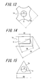
FIG. 13 is a top view showing yet another pin configuration of the tire stud of the present invention. -
FIG. 14 is a top view showing yet another pin configuration of the tire stud of the present invention. -
FIG. 15 is a top view showing yet another pin configuration of the tire stud of the present invention. -
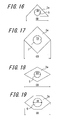
FIG. 16 is a top view showing yet another pin configuration of the tire stud of the present invention. -
FIG. 17 is a top view showing yet another pin configuration of the tire stud of the present invention. -
FIG. 18 is a top view showing yet another pin configuration of the tire stud of the present invention. -
FIG. 19 is a top view showing yet another pin configuration of the tire stud of the present invention. -
FIG. 20 is a top view showing yet another pin configuration of the tire stud of the present invention. -
FIG. 21 is a top view showing yet another pin configuration of the tire stud of the present invention. -
FIG. 22 is a top view showing yet another pin configuration of the tire stud of the present invention. -
FIG. 23 is a top view showing yet another pin configuration of the tire stud of the present invention. -
FIG. 24 is a top view showing a conventional pin configuration of a tire stud. -
FIG. 25 is a top view showing another conventional pin configuration of a tire stud. -
FIG. 26 is a top view showing yet another pin configuration of the tire stud of the present invention. - The present invention will be described in detail with reference to the drawings hereinafter.
-
FIG. 2 is a front view showing a tire stud (which will be referred to simply as a "stud" hereinafter) according to one embodiment of the present invention.
As shown inFIG. 2 , thestud 1 of the one embodiment of the present invention has: a substantiallycylindrical body 2; a column-like pin 3 provided in a recessed portion formed in oneend face 2a in the axial direction of the body 2 (in the direction of the central axis C extending in the longitudinal direction of the body 2); and aflange 4 provided integral with thecylindrical body 2 on the other end face side in the axis C direction of thebody 2 for preventing the stud from coming off. -
FIG. 3 is a schematic perspective view showing a pin configuration of the stud according to the one embodiment of the present invention.
As shown inFIG. 3 , thepin 3 has at least one hole 5 (a single hole in an example shown inFIG. 3 ) formed in anupper surface 3a of the pin 3 (theupper surface 3a is an end face to be brought into contact with a road surface) so as to extend in the axial direction of thepin 3, i.e. the direction of the central axis D extending in the longitudinal direction of the pin).
Thehole 5 is rectangular in a cross section cut in the radial direction of the pin 3 (the cross section orthogonal to the central axis D) and terminates within thepin 3 without penetrating through thepin 3 in the axial direction thereof in the example shown inFIG. 3 .
Further, thestud 1 of the present embodiment satisfies, provided that the maximum height measured from the oneend face 2a of thebody 2 to theupper surface 3a of thepin 3 is h (mm) and the maximum depth of thehole 5 formed in theupper surface 3a of thepin 3 is d (mm) as shown inFIG. 2 andFIG. 3 , 0.1 ≤ d/h ≤ 0.5.
An effect obtained in a case where thestuds 1, each having thepin 3 of the aforementioned configuration provided in the recessed portion thereof, are fitted inpit holes 7 formed in a ground-contact surface 6 of a tread of a studded tire as shown inFIG. 4 will be described hereinafter. - According to the present invention, the hole(s) 5 is formed in the
upper surface 3a of thepin 3, so that edge(s) demarcated by the hole(s) 5 in theupper surface 3 a of thepin 3 constitute additional edge components to be brought into contact with an ice road when a vehicle runs on the ice road. These edge components thus increased on an ice road significantly improve braking performance of the tire on the ice road.
More specifically, when the ratio d/h is less than 0.1, thehole 5 is too shallow to cause a satisfactory edge effect when thepin 3 is dragged on ice. The ratio d/h exceeding 0.5 results in too deep a hole with insufficient strength, whereby the pin (the upper surface thereof in particular) is likely to be chipped not only when the pin is dragged on ice but also even during normal running on a dry road. An advantageous effect of improving braking performance on ice can no longer be pursued when the total edge length of the pin has decreased due to such chipping of the pin in the present invention.
Further, according to the present invention, thehole 5 extends in the axial direction of thepin 3, so that additional edge components as the edges demarcated by the hole constantly appear and thus successfully improve braking performance of the tire on an ice road even when thepin 3 is worn.
Yet further, according to the present invention, thehole 5 terminates within thepin 3 without penetrating through the pin in the axial direction thereof, whereby it is possible to ensure sufficient strength of thepin 3 to suppress breakage such as cracking of the pin. Yet further, according to the present invention, weight of thepin 3 is reduced due to formation of thehole 5 therein. - As shown in
FIG. 5 , plural holes (two holes in an example shown inFIG. 5 ) may be formed in the upper surface of thepin 3 in the present embodiment.
Braking performance of the tire on an ice road can be further improved in this case due to further increase in the edge components to be brought into contact with a road surface. - In the present embodiment, provided that hypothetical cross sectional area with no holes formed therein of the
pin 3 is S1 and the total cross sectional area of the hole 5 (the sum of cross sectional areas of theholes 5 whenplural holes 5 are formed) is S2 in a cross section orthogonal to the axial direction of thepin 3, the ratio S2/S1 preferably satisfies 0.1 ≤ S2/S1 ≤ 0.5.
Sufficient lengths of edges demarcated by the hole(s) can be ensured and thus the edge components are sufficiently increased at the upper surface of the pin, so that a satisfactorily high edge effect can be obtained, by setting the ratio S2/S1 to be at least 0.1. The area of theupper surface 3 a of thepin 3 is prevented from being too small to ensure satisfactory strength of thepin 3, that is, breakage of the pin such as cracking at edge portions thereof can be well suppressed, by setting the ratio S2/S1 to be 0.5 or less. - The
hole 5 preferably terminates within thepin 3 without penetrating through the pin in the axial direction thereof because then rigidity of the pin is ensured and breakage of the pin such as cracking can be suppressed. - Further, the
hole 5 preferably has a rectangular configuration in a cross section in the radial direction of the pin 3 (a cross section orthogonal to the axial direction of the pin), as shown inFIG. 3 andFIG. 5 . However, the cross sectional configuration of thehole 5 is not limited to a rectangular shape but may be any of other various shapes including circular, oval, and polygonal shapes.
In this connection, thehole 5 may have a configuration of which cross sectional area changes in the axial direction of thepin 3, as shown inFIG. 6 . - Yet further, in the present invention, provided that the maximum diameter of the upper surface of the pin is OD (mm) and the total edge length at the upper surface of the pin is L (mm), OD and L/OD preferably satisfy 2.0 ≤ OD ≤ 4.0 and 3.0 ≤ L/OD ≤ 9.0, respectively.
OD ≥ 2.0 mm ensures the minimally required size of the pin itself, thereby ensuring the minimally required lengths of outer peripheral edges at the upper surface of the pin and thus the minimally required braking performance of the tire on ice. OD ≤ 4.0 mm avoids too large a size of the pin itself, thereby decreasing counterforce from a road surface during running on a dry road surface to ensure that the tire exhibits generally required resistance to stud-coming off.
A sufficiently large non-hole area of the upper surface of the pin and thus satisfactorily high strength of the pin are ensured, in other words, breakage such as cracking of the edge portions of the pin due to insufficient strength of the pin is well suppressed, by setting the ratio L/OD to be in the aforementioned range. That is, deterioration of braking performance of the tire on ice due to breakage of the pin can be well suppressed by setting the ratio L/OD to be in the aforementioned range. - Further, in the present invention, provided that the maximum diameter of the
hole 5 is ID (mm), the ratio ID/OD preferably satisfies 0.15 ≤ ID/OD ≤ 0.8.
The ratio ID/OD ≥ 0.15 ensures ample edge components working when the pin is dragged on ice, thereby further improving braking performance of the tire on ice.
The ratio ID/OD ≤ 0.8 ensures sufficiently high strength of the upper surface of the pin, thereby well suppressing breakage such as cracking of edge portions of the pin. In short, deterioration of braking performance of the tire on ice due to breakage of the pin can be well suppressed by setting the ratio ID/OD to be 0.8 or less. - Yet further, the one end face of the body preferably has a circular shape in the present invention.
As soon as pin edges of studs have been hooked by an ice road surface in a brake operation, the studs are dragged and sequentially fall forward relative to a direction normal to a tire tread in which each of the studs was originally fitted in the tread. An Edge portion of the one end face of the body is then brought into contact with the ice road surface when each stud falls forward to a certain degree, thereby inhibiting the originally intended ice-scratching effect caused by the pin edges.
In the present invention, however, angles at which the studs topple to bring the edges of the bodies thereof into contact with an ice road surface are made even regardless of the locations of the studs because each one end face of the body of each stud is circular. Accordingly, it is possible in the present invention to suppress variation in pin edge performances of the studs and thus comprehensively ensure good tire performances not only in braking performance in straight running but also in braking and gripping performances in various situations including a cornering situation. - Yet further, in the present invention, provided that: radius measured from the central axis C of the body to an outer peripheral edge of the
flange 4 is R (mm); the maximum value of radius R on one side in the tire circumferential direction is Rf (mm); and the maximum value of radius R on the other side in the tire circumferential direction is Rk (mm) as shown inFIG. 2 andFIG. 7A , it is preferable that Rf ≤ Rk.
In this connection, an effect caused when the tire of the present invention is mounted on a vehicle such that the aforementioned "one side in the tire circumferential direction" corresponds to the leading end side and the aforementioned "the other side in the tire circumferential direction" corresponds to the trailing end side will be described hereinafter.
During a brake operation, the body of each stud in contact with an ice surface falls forward, i.e. in the direction of movement of the vehicle, in a state where the pin edges are hooked by the ice surface. In this regard, a degree of the body falling forward or in the direction of movement of the vehicle can be made relatively small when the aforementioned relationship formula Rf ≤ Rk is satisfied, which makes it possible to effectively maintain the ice-scratching effect by the pin edges to improve on-ice braking performance of the tire. - Further, in addition to the definitions of R, Rf and Rk, provided that: the maximum value of radius R on the inner side in the tire widthwise direction is Ri (mm); and the maximum value of radius R on the outer side in the tire widthwise direction is Ro (mm), Rf, Rk, Ri and Ro are each preferably in the range of 3.0 mm to 5.0 mm (inclusive of 3.0 mm and 5.0 mm).
It is possible to suppress aforementioned toppling of the studs in starting, braking and cornering situations and the like to ensure good resistance to stud-coming off of the tire by setting radius of the flange to be at least 3.0 mm. It is possible to facilitate and ensure firm embedment of the studs when the studs are fitted in the pit holes formed in a tire tread, thereby ensuring good resistance to stud-coming off of the tire, by setting radius of the flange to be 5.0 mm or less. - Yet further, the
pin 3 may have various types of cross sectional configurations including oval, rectangular, polygonal, cross and the like in the present invention, as shown inFIGS. 8 to 23 and26 . - Test studs as Examples 1 to 40 and Comparative Examples 1, 2 each having a pin with a hole formed in an upper surface thereof were prepared in order to confirm an effect of the present invention.
Further, test studs as Conventional Examples 1, 2 each having a pin without a hole formed in an upper surface thereof were also prepared.
The test studs of each of these Examples, Comparative Examples and Conventional Examples were fitted in pit holes formed in a ground-contact surface of a tread portion of a tire having tire size: 195/ 65R15, whereby test tires of Examples, Comparative Examples and Conventional Examples were prepared. Each of the test tires was subjected to following tests at internal pressure of 230 kPa for evaluating performances of the tire. - Braking performance on ice of a studded tire was evaluated by: a test driver hitting the brakes suddenly on a test course having an ice road surface when a vehicle with relevant test tires mounted thereon was running at the initial speed of 20 km/hour; measuring a braking distance travelled by the vehicle in a period from the sudden brakes to a moment when the vehicle completely stopped; obtaining a reciprocal of the braking distance value thus measured; and converting each reciprocal value to an index value relative to the reciprocal value of the test tire of Conventional Example 2 being "100". The larger index value represents the better braking performance on an ice road surface.
- Resistance to stud-coming off of a studded tire was evaluated by: running a vehicle with relevant new test tires mounted thereon by 30,000 km on ice/snow and dry road surfaces, respectively; counting the number of the studs which had come off from the tires after the running; calculating ratio of the number of the studs which had come off with respect to the number of all studs initially fitted in the tires; and converting each ratio to an index value relative to the ratio of the test tire of Conventional Examples 1, 2 being "100". The smaller index value represents the higher resistance to stud-coming off.
The evaluation results, as well as the relevant characteristics, of the test tires are shown in Table 1 below.
Each of the test tires was mounted on a vehicle such that the aforementioned "one side in the tire circumferential direction" corresponds to the leading end side and the aforementioned "the other side in the tire circumferential direction" corresponds to the trailing end side thereof.Table 1-1 Example 1 Example 2 Example 3 Comp. Ex. 1 Comp. Ex. 2 Example 4 Example 5 Example 6 Example 7 Example 8 Example 9 Example 10 Example 11 Example 12 Configuration of body FIG. 2 FIG. 2 FIG. 2 FIG. 2 FIG. 2 FIG. 2 FIG.2 FIG. 2 FIG. 2 FIG. 2 FIG. 2 FIG. 2 FIG. 2 FIG. 2 Column-like Column-like Column-like Column-like Column-like Column-like Column-like Column-like Column-like Column-like Column-like Column-like Column-like Column-like Configuration of upper surface of pin FIG. 8 FIG. 8 FIG. 8 FIG. 8 FIG. 8 FIG. 8 FIG. 8 FIG. 8 FIG. 8 FIG. 8 FIG. 8 FIG. 8 FIG. 9 FIG. 10 Oval Oval Oval Oval Oval Oval Oval Oval Oval Oval Oval Oval Oval Oval Number of hole(s) 1 1 1 1 1 1 1 1 1 1 1 1 2 4 Configuration of hole Oval Oval Oval Oval Oval Oval Oval Oval Oval Oval Oval Oval Circular Sector-shaped ID(mm) 1.36 1.36 1.36 1.36 1.36 1.36 1.36 1.36 1.36 1.10 2.30 0.46 0.68 0.90 d(mm) 0.30 0.40 0.22 0.30 0.30 0.30 0.30 0.30 0.30 0.30 0.30 0.30 0.30 0.30 OD(mm) 2.90 2.90 2.90 2.90 2.90 2.00 4.00 1.90 4.10 2.90 2.90 2.90 2.90 2.90 h(mm) 1.20 0.80 2.00 1.20 1.20 1.20 1.20 1.20 1.20 1.20 1.20 1.20 1.20 1.20 ID/OD 0.47 0.47 0.47 0.47 0.47 0.68 0.34 0.72 0.33 0.38 0.79 0.16 0.23 0.31 d/h 0.25 0.50 0.11 0.51 0.09 0.25 0.25 0.25 0.25 0.25 0.25 0.25 0.25 0.25 L 9.2 10.3 10.3 10.3 10.3 8.1 13.0 7.9 13.2 9.7 12.6 8.1 11.3 16.2 L/OD 3.16 3.16 3.16 3.16 3.16 3.49 2.95 3.54 2.94 3.02 3.67 2.67 3.89 5.58 Rf 4.1 4.1 4.1 4.1 4.1 4.1 4.1 4.1 4.1 4.1 4.1 4.1 4.1 4.1 Rk 4.1 4.1 4.1 4.1 4.1 4.1 4.1 4.1 4.1 4.1 4.1 4.1 4.1 4.1 Ri 4.1 4.1 4.1 4.1 4.1 4.1 4.1 4.1 4.1 4.1 4.1 4.1 4.1 4.1 Ro 4.1 4.1 4.1 4.1 4.1 4.1 4.1 4.1 4.1 4.1 4.1 4.1 4.1 4.1 Braking performance on ice (INDEX) 103 101 104 99 98 102 105 101 106 103 104 102 104 105 Resistance to stud-coming off (INDEX) 100 100 100 100 100 98 100 98 100 100 100 100 100 100 Table 1-2 Example 13 Example 14 Example 15 Example 16 Example 17 Example 18 Example 19 Example 20 Example 21 Example 22 Example 23 Example 24 Example 25 Example 26 Example 27 Configuration of body FIG. 2 FIG. 2 FIG. 2 FIG. 2 FIG. 2 FIG. 2 FIG. 2 FIG. 2 FIG. 2 FIG. 2 FIG. 2 FIG. 2 FIG. 2 FIG. 2 FIG. 2 Column-like Column-like Column-like Column-like Column-like Column-like Column-like Column-like Column-like Column-like Column-like Column-like Column-like Column-like Column-like Configuration of upper surface of pin FIG. 11 FIG. 26 FIG. 8 FIG. 8 FIG. 12 FIG. 13 FIG. 13 FIG. 13 FIG. 13 FIG. 13 FIG. 13 FIG. 13 FIG. 13 FIG. 13 FIG. 13 Rectangular Rectangular Oval Oval Circular Cross Cross Cross Cross Cross Cross Cross Cross Cross Cross Number of hole(s) 4 8 1 1 1 1 1 1 1 1 1 1 1 1 1 Configuration of hole Rectang ular Square Oval Oval Circular Circular Circular Circular Circular Circular Circular Circular Circular Circular Circular ID(mm) 1.00 0.75 2.32 0.40 1.36 1.00 1.00 1.00 1.00 1.00 1.00 1.00 1.00 1.00 1.00 d(mm) 0.30 0.30 0.30 0.30 0.30 0.30 0.30 0.30 0.30 0.30 0.30 0.30 0.30 0.30 0.30 OD(mm) 2.90 2.90 2.90 2.90 2.90 2.90 2.90 2.90 2.90 2.90 2.90 2.90 2.90 2.90 2.90 h(mm) 1.20 1.20 1.20 1.20 1.20 1.20 1.20 1.20 1.20 1.20 1.20 1.20 1.20 1.20 1.20 ID/OD 0.34 0.26 0.80 0.14 0.47 0.34 0.34 0.34 0.34 0.34 0.34 0.34 0.34 0.34 0.34 d/h 0.25 0.25 0.25 0.25 0.25 0.25 0.25 0.25 0.25 0.25 0.25 0.25 0.25 0.25 0.25 L 19.1 26.4 12.6 8.0 13.4 15.4 15.4 15.4 15.4 15.4 15.4 15.4 15.4 15.4 15.4 L/OD 6.59 9.10 4.36 2.75 4.61 5.33 5.33 5.33 5.33 5.33 5.33 5.33 5.33 5.33 5.33 Rf 4.1 4.1 4.1 4.1 4.1 4.1 3.3 4.1 2.9 3.1 5.0 5.1 4.1 4.1 4.1 Rk 4.1 4.1 4.1 4.1 4.1 4.1 4.9 4.9 4.9 5.1 4.0 4.1 2.9 5.1 4.1 Ri 4.1 4.1 4.1 4.1 4.1 4.1 4.1 4.1 4.1 4.1 4.1 4.1 4.1 4.1 2.9 Ro 4.1 4.1 4.1 4.1 4.1 4.1 4.1 4.1 4.1 4.1 4.1 4.1 4.1 4.1 4.1 Braking performance on ice (INDEX) 104 102 105 101 104 105 106 107 105 105 105 104 103 107 105 Resistance to stud-coming off (INDEX) 100 100 100 100 100 100 99 98 99 97 100 102 103 101 102 Table 1-3 Example 28 Example 29 Example 30 Example 31 Example 32 Example 33 Example 34 Example 35 Example 36 Example 37 Example 38 Example 39 Example 40 Conventional Ex. 1 Conventi onal Ex. 2 Configuration of body FIG. 2 FIG. 2 FIG. 2 FIG. 2 FIG. 2 FIG. 2 FIG. 2 FIG. 2 FIG. 2 FIG. 2 FIG. 2 FIG. 2 FIG. 2 - - Column-like Column-like Column-like Column-like Column-like Column-like Column-like Column-like Column-like Column-like Column-like Column-like Column-like Column-like Column -like Configuration of upper surface of pin FIG. 13 FIG. 13 FIG. 13 FIG. 14 FIG. 15 FIG. 16 FIG. 17 FIG. 18 FIG. 19 FIG. 20 FIG. 21 FIG. 22 FIG. 23 FIG. 24 FIG. 25 Cross Cross Cross Rectangular Equilateral triangular Isosceles triangular Square Rhomboid Hexagonal Concave octagonal Concave decagonal Cross Modified cross Circular Oval Number of hole(s) 1 1 1 1 1 1 1 1 1 1 1 1 1 - - Configuration of hole Circular Circular Circular Rectangular Circular Circular Circular Circular Circular Circular Circular Circular Rectangular - - ID(mm) 1.00 1.00 1.00 2.00 1.00 0.68 1.00 0.68 1.00 1.00 1.00 1.00 1.00 - - d(mm) 0.30 0.30 0.30 0.30 0.30 0.30 0.30 0.30 0.30 0.30 0.30 0.30 0.30 - - OD(mm) 2.90 2.90 2.90 2.90 2.90 2.90 2.90 2.90 2.90 2.90 2.90 2.90 2.90 2.90 2.90 h(mm) 1.20 1.20 1.20 1.20 1.20 1.20 1.20 1.20 1.20 1.20 1.20 1.20 1.20 1.20 1.20 ID/OD 0.34 0.34 0.34 0.69 0.34 0.23 0.34 0.23 0.34 0.34 0.34 0.34 0.34 - - d/h 0.25 0.25 0.25 0.25 0.25 0.25 0.25 0.25 0.25 0.25 0.25 0.25 0.25 - - L 15.4 15.4 15.4 14.7 11.8 9.1 14.7 8.8 9.5 15.2 11.3 15.4 14.1 9.1 7.0 L/OD 5.33 5.33 5.33 5.07 4.08 3.15 5.08 3.05 3.29 5.22 3.91 5.33 4.87 3.14 2.42 Rf 4.1 4.1 4.1 4.1 4.1 4.1 4.1 4.1 4.1 4.1 4.1 4.1 4.1 4.1 4.1 Rk 4.1 4.1 4.1 4.1 4.1 4.1 4.1 4.1 4.1 4.1 4.1 4.1 4.1 4.1 4.1 Ri 5.1 4.1 4.1 4.1 4.1 4.1 4.1 4.1 4.1 4.1 4.1 4.1 4.1 4.1 4.1 Ro 4.1 2.9 5.1 4.1 4.1 4.1 4.1 4.1 4.1 4.1 4.1 4.1 4.1 4.1 4.1 Braking performance on ice (INDEX) 105 105 105 103 103 102 104 102 102 104 104 105 103 101 100 Resistance to stud-coming off (INDEX) 101 102 101 100 100 99 100 99 100 100 100 100 100 100 100 - It is understood from Tables 1-1 to 1-3 that the test tires of Examples 1-40 unanimously exhibit better braking performance on ice than the test tires of Conventional Examples and Comparative Examples.
-
- 1
- Stud
- 2
- Body (Shank)
- 2a
- End face
- 3
- Pin
- 4
- Flange
- 5
- Hole
- 6
- Ground-contact surface of tread portion
- 7
- Pit hole
- 10
- Tread portion
- 11
- Stud
- 12
- Pin
- 13
- Road surface
- 14
- Pit hole
- 15
- Body (Shank)
Claims (7)
- A tire stud, comprising: a column-like body having a recessed portion formed at one end face in the axial direction thereof; and a pin provided in the recessed portion such that a portion of the pin protrudes from the one end face of the body, characterized in that:at least one hole extending in the axial direction of the pin is formed in an upper surface of the pin; andprovided that the maximum height measured from the one end face of the body to the upper surface of the pin is h (mm) and the maximum depth of the hole formed in the upper surface of the pin is d (mm), 0.1 ≤ d/h ≤ 0.5.
- The tire stud of claim 1, wherein provided that the maximum diameter of the upper surface of the pin is OD (mm) and the total edge length at the upper surface of the pin is L (mm), 2.0 ≤ OD ≤ 4.0 and 3.0 ≤ L/OD ≤ 9.0.
- The tire stud of claim 1 or 2, wherein provided that the maximum diameter of the upper surface of the pin is OD (mm) and the maximum diameter of the hole formed in the upper surface of the pin is ID (mm), 0.15 ≤ ID/OD ≤ 0.8.
- The tire stud of any of claims 1 to 3, wherein the one end face of the body has a circular shape.
- The tire stud of any of claims 1 to 4, wherein the body has a flange and provided that: radius measured from the central axis of the body to an outer peripheral edge of the flange is R (mm); the maximum value of radius R on one side in the tire circumferential direction is Rf (mm); and the maximum value of radius R on the other side in the tire circumferential direction is Rk (mm), Rf ≤ Rk.
- The tire stud of any of claims 1 to 5, wherein the body has a flange and provided that: radius measured from the central axis of the body to an outer peripheral edge of the flange is R (mm); the maximum value of radius R on one side in the tire circumferential direction is Rf (mm); the maximum value of radius R on the other side in the tire circumferential direction is Rk (mm); the maximum value of radius R on the inner side in the tire widthwise direction is Ri (mm); and the maximum value of radius R on the outer side in the tire widthwise direction is Ro (mm), Rf, Rk, Ri and Ro are each in the range of 3.0 mm to 5.0 mm (inclusive of 3.0 mm and 5.0 mm).
- A studded tire, comprising the tire studs of any of claims 1 to 6 fitted in pit holes formed in a ground-contact surface of a tread thereof.
Applications Claiming Priority (2)
| Application Number | Priority Date | Filing Date | Title |
|---|---|---|---|
| JP2011161203A JP6111010B2 (en) | 2011-07-22 | 2011-07-22 | Tire spikes and spike tires |
| PCT/JP2012/004640 WO2013014900A1 (en) | 2011-07-22 | 2012-07-20 | Stud for tire, and studded tire |
Publications (3)
| Publication Number | Publication Date |
|---|---|
| EP2735454A1 true EP2735454A1 (en) | 2014-05-28 |
| EP2735454A4 EP2735454A4 (en) | 2015-06-24 |
| EP2735454B1 EP2735454B1 (en) | 2016-09-07 |
Family
ID=47600771
Family Applications (1)
| Application Number | Title | Priority Date | Filing Date |
|---|---|---|---|
| EP12817248.3A Not-in-force EP2735454B1 (en) | 2011-07-22 | 2012-07-20 | Stud for tire, and studded tire |
Country Status (4)
| Country | Link |
|---|---|
| EP (1) | EP2735454B1 (en) |
| JP (1) | JP6111010B2 (en) |
| RU (1) | RU2566802C2 (en) |
| WO (1) | WO2013014900A1 (en) |
Families Citing this family (4)
| Publication number | Priority date | Publication date | Assignee | Title |
|---|---|---|---|---|
| JP5702817B2 (en) * | 2013-03-19 | 2015-04-15 | 株式会社ブリヂストン | Stud pin and tire using the same |
| JP6659518B2 (en) * | 2016-10-26 | 2020-03-04 | Toyo Tire株式会社 | Stud pin |
| JP6806936B2 (en) * | 2020-02-06 | 2021-01-06 | Toyo Tire株式会社 | Stud pin |
| JP7063350B2 (en) * | 2020-06-01 | 2022-05-09 | 横浜ゴム株式会社 | Stud pins and tires with them |
Family Cites Families (20)
| Publication number | Priority date | Publication date | Assignee | Title |
|---|---|---|---|---|
| JPS4818761B1 (en) * | 1970-11-07 | 1973-06-08 | ||
| JPS4984801U (en) * | 1972-11-10 | 1974-07-23 | ||
| JPS5031607U (en) * | 1973-07-18 | 1975-04-08 | ||
| JPS58113505U (en) * | 1982-01-29 | 1983-08-03 | 横浜ゴム株式会社 | tire spikes |
| JPS61232904A (en) * | 1985-04-09 | 1986-10-17 | Bridgestone Corp | Spike pin capable of reducing damage of road surface |
| JPH08118920A (en) * | 1994-10-21 | 1996-05-14 | Goichi Gomme Kk | Antiskid means and tire with antiskid means |
| JP3037216U (en) * | 1996-10-25 | 1997-05-16 | 株式会社ニューテクノ | Tire spike |
| JPH10193921A (en) * | 1997-01-06 | 1998-07-28 | Maruemu:Kk | Structure of spike pin |
| FI110242B (en) * | 1997-03-07 | 2002-12-31 | Nokian Renkaat Oy | Lamelliliukueste |
| JP2994603B2 (en) * | 1997-03-24 | 1999-12-27 | 一男 小島 | Tire with pin device and pin device |
| JP3042577U (en) * | 1997-04-16 | 1997-10-21 | 株式会社マルエム | Anti-slip spikes |
| JPH11198613A (en) * | 1998-01-16 | 1999-07-27 | Hirokimi Doi | Snow tipe |
| JPH11254915A (en) * | 1998-03-10 | 1999-09-21 | Bridgestone Corp | Spike pin, manufacture of spike pin, and tire antiskid device |
| RU2159705C1 (en) * | 1999-04-07 | 2000-11-27 | Корниенко Александр Васильевич | Anti-skid stud body (versions) |
| RU16476U1 (en) * | 2000-08-17 | 2001-01-10 | Корниенко Александр Васильевич | ANTISKID SPIKE HOUSING (OPTIONS) |
| FI119182B (en) * | 2005-12-16 | 2008-08-29 | Scason Oy | Double for double deck |
| JP2008284922A (en) * | 2007-05-15 | 2008-11-27 | Yokohama Rubber Co Ltd:The | Pneumatic tire |
| JP5359145B2 (en) * | 2008-09-18 | 2013-12-04 | 横浜ゴム株式会社 | Pneumatic tire |
| JP5379444B2 (en) * | 2008-10-20 | 2013-12-25 | 株式会社ブリヂストン | Tire spike |
| NO330285B1 (en) * | 2009-05-05 | 2011-03-21 | Hans Husevag | Spike to deck |
-
2011
- 2011-07-22 JP JP2011161203A patent/JP6111010B2/en not_active Expired - Fee Related
-
2012
- 2012-07-20 RU RU2014106524/11A patent/RU2566802C2/en active
- 2012-07-20 EP EP12817248.3A patent/EP2735454B1/en not_active Not-in-force
- 2012-07-20 WO PCT/JP2012/004640 patent/WO2013014900A1/en not_active Ceased
Also Published As
| Publication number | Publication date |
|---|---|
| RU2014106524A (en) | 2015-08-27 |
| WO2013014900A1 (en) | 2013-01-31 |
| RU2566802C2 (en) | 2015-10-27 |
| JP2013023112A (en) | 2013-02-04 |
| JP6111010B2 (en) | 2017-04-05 |
| EP2735454B1 (en) | 2016-09-07 |
| EP2735454A4 (en) | 2015-06-24 |
Similar Documents
| Publication | Publication Date | Title |
|---|---|---|
| JP5702817B2 (en) | Stud pin and tire using the same | |
| JP2013023111A (en) | Tire stud and studded tire | |
| JP2013091445A (en) | Pneumatic tire for heavy load | |
| JP6029910B2 (en) | Pneumatic tire | |
| US10464377B2 (en) | Winter tire | |
| JP5997519B2 (en) | Pins, tire studs and spike tires | |
| CN106183645A (en) | Winter tire | |
| EP2735454B1 (en) | Stud for tire, and studded tire | |
| JP5695722B2 (en) | Heavy duty pneumatic tire | |
| EP3202593A1 (en) | Pneumatic tire | |
| JP2008290573A (en) | Pneumatic tire | |
| JP5883246B2 (en) | Tire spikes and spike tires | |
| JP5809023B2 (en) | Pneumatic tire | |
| WO2006062156A1 (en) | Pneumatic tire | |
| JP5337678B2 (en) | Pneumatic tire | |
| CA3040256C (en) | Stud pin and pneumatic tire provided with stud pin | |
| CA3040262C (en) | Stud pin, and pneumatic tire provided with stud pin | |
| JP4634644B2 (en) | Pneumatic tire | |
| CA3040260C (en) | Stud pin, and pneumatic tire provided with stud pin | |
| JP5771468B2 (en) | Tire spikes and spike tires | |
| JPH02254004A (en) | Heavy duty pneumatic radial tire for ice load | |
| EP3698985B1 (en) | Tire | |
| WO2014006858A1 (en) | Pin, tire stud and studded tire | |
| JP2010115988A (en) | Pneumatic tire | |
| RU166454U1 (en) | SNIP SPIK |
Legal Events
| Date | Code | Title | Description |
|---|---|---|---|
| PUAI | Public reference made under article 153(3) epc to a published international application that has entered the european phase |
Free format text: ORIGINAL CODE: 0009012 |
|
| 17P | Request for examination filed |
Effective date: 20140109 |
|
| AK | Designated contracting states |
Kind code of ref document: A1 Designated state(s): AL AT BE BG CH CY CZ DE DK EE ES FI FR GB GR HR HU IE IS IT LI LT LU LV MC MK MT NL NO PL PT RO RS SE SI SK SM TR |
|
| DAX | Request for extension of the european patent (deleted) | ||
| RA4 | Supplementary search report drawn up and despatched (corrected) |
Effective date: 20150522 |
|
| RIC1 | Information provided on ipc code assigned before grant |
Ipc: B60C 11/16 20060101AFI20150518BHEP |
|
| GRAP | Despatch of communication of intention to grant a patent |
Free format text: ORIGINAL CODE: EPIDOSNIGR1 |
|
| INTG | Intention to grant announced |
Effective date: 20160229 |
|
| GRAS | Grant fee paid |
Free format text: ORIGINAL CODE: EPIDOSNIGR3 |
|
| GRAA | (expected) grant |
Free format text: ORIGINAL CODE: 0009210 |
|
| AK | Designated contracting states |
Kind code of ref document: B1 Designated state(s): AL AT BE BG CH CY CZ DE DK EE ES FI FR GB GR HR HU IE IS IT LI LT LU LV MC MK MT NL NO PL PT RO RS SE SI SK SM TR |
|
| REG | Reference to a national code |
Ref country code: GB Ref legal event code: FG4D |
|
| REG | Reference to a national code |
Ref country code: CH Ref legal event code: EP |
|
| REG | Reference to a national code |
Ref country code: IE Ref legal event code: FG4D |
|
| REG | Reference to a national code |
Ref country code: AT Ref legal event code: REF Ref document number: 826492 Country of ref document: AT Kind code of ref document: T Effective date: 20161015 |
|
| REG | Reference to a national code |
Ref country code: DE Ref legal event code: R096 Ref document number: 602012022594 Country of ref document: DE |
|
| REG | Reference to a national code |
Ref country code: SE Ref legal event code: TRGR |
|
| REG | Reference to a national code |
Ref country code: LT Ref legal event code: MG4D |
|
| REG | Reference to a national code |
Ref country code: NL Ref legal event code: MP Effective date: 20160907 |
|
| REG | Reference to a national code |
Ref country code: NO Ref legal event code: T2 Effective date: 20160907 |
|
| PG25 | Lapsed in a contracting state [announced via postgrant information from national office to epo] |
Ref country code: HR Free format text: LAPSE BECAUSE OF FAILURE TO SUBMIT A TRANSLATION OF THE DESCRIPTION OR TO PAY THE FEE WITHIN THE PRESCRIBED TIME-LIMIT Effective date: 20160907 Ref country code: LT Free format text: LAPSE BECAUSE OF FAILURE TO SUBMIT A TRANSLATION OF THE DESCRIPTION OR TO PAY THE FEE WITHIN THE PRESCRIBED TIME-LIMIT Effective date: 20160907 Ref country code: RS Free format text: LAPSE BECAUSE OF FAILURE TO SUBMIT A TRANSLATION OF THE DESCRIPTION OR TO PAY THE FEE WITHIN THE PRESCRIBED TIME-LIMIT Effective date: 20160907 |
|
| REG | Reference to a national code |
Ref country code: AT Ref legal event code: MK05 Ref document number: 826492 Country of ref document: AT Kind code of ref document: T Effective date: 20160907 |
|
| PG25 | Lapsed in a contracting state [announced via postgrant information from national office to epo] |
Ref country code: GR Free format text: LAPSE BECAUSE OF FAILURE TO SUBMIT A TRANSLATION OF THE DESCRIPTION OR TO PAY THE FEE WITHIN THE PRESCRIBED TIME-LIMIT Effective date: 20161208 Ref country code: LV Free format text: LAPSE BECAUSE OF FAILURE TO SUBMIT A TRANSLATION OF THE DESCRIPTION OR TO PAY THE FEE WITHIN THE PRESCRIBED TIME-LIMIT Effective date: 20160907 Ref country code: ES Free format text: LAPSE BECAUSE OF FAILURE TO SUBMIT A TRANSLATION OF THE DESCRIPTION OR TO PAY THE FEE WITHIN THE PRESCRIBED TIME-LIMIT Effective date: 20160907 Ref country code: NL Free format text: LAPSE BECAUSE OF FAILURE TO SUBMIT A TRANSLATION OF THE DESCRIPTION OR TO PAY THE FEE WITHIN THE PRESCRIBED TIME-LIMIT Effective date: 20160907 |
|
| PG25 | Lapsed in a contracting state [announced via postgrant information from national office to epo] |
Ref country code: RO Free format text: LAPSE BECAUSE OF FAILURE TO SUBMIT A TRANSLATION OF THE DESCRIPTION OR TO PAY THE FEE WITHIN THE PRESCRIBED TIME-LIMIT Effective date: 20160907 Ref country code: EE Free format text: LAPSE BECAUSE OF FAILURE TO SUBMIT A TRANSLATION OF THE DESCRIPTION OR TO PAY THE FEE WITHIN THE PRESCRIBED TIME-LIMIT Effective date: 20160907 |
|
| PG25 | Lapsed in a contracting state [announced via postgrant information from national office to epo] |
Ref country code: AT Free format text: LAPSE BECAUSE OF FAILURE TO SUBMIT A TRANSLATION OF THE DESCRIPTION OR TO PAY THE FEE WITHIN THE PRESCRIBED TIME-LIMIT Effective date: 20160907 Ref country code: PL Free format text: LAPSE BECAUSE OF FAILURE TO SUBMIT A TRANSLATION OF THE DESCRIPTION OR TO PAY THE FEE WITHIN THE PRESCRIBED TIME-LIMIT Effective date: 20160907 Ref country code: CZ Free format text: LAPSE BECAUSE OF FAILURE TO SUBMIT A TRANSLATION OF THE DESCRIPTION OR TO PAY THE FEE WITHIN THE PRESCRIBED TIME-LIMIT Effective date: 20160907 Ref country code: BE Free format text: LAPSE BECAUSE OF FAILURE TO SUBMIT A TRANSLATION OF THE DESCRIPTION OR TO PAY THE FEE WITHIN THE PRESCRIBED TIME-LIMIT Effective date: 20160907 Ref country code: SK Free format text: LAPSE BECAUSE OF FAILURE TO SUBMIT A TRANSLATION OF THE DESCRIPTION OR TO PAY THE FEE WITHIN THE PRESCRIBED TIME-LIMIT Effective date: 20160907 Ref country code: SM Free format text: LAPSE BECAUSE OF FAILURE TO SUBMIT A TRANSLATION OF THE DESCRIPTION OR TO PAY THE FEE WITHIN THE PRESCRIBED TIME-LIMIT Effective date: 20160907 Ref country code: BG Free format text: LAPSE BECAUSE OF FAILURE TO SUBMIT A TRANSLATION OF THE DESCRIPTION OR TO PAY THE FEE WITHIN THE PRESCRIBED TIME-LIMIT Effective date: 20161207 Ref country code: PT Free format text: LAPSE BECAUSE OF FAILURE TO SUBMIT A TRANSLATION OF THE DESCRIPTION OR TO PAY THE FEE WITHIN THE PRESCRIBED TIME-LIMIT Effective date: 20170109 Ref country code: IS Free format text: LAPSE BECAUSE OF FAILURE TO SUBMIT A TRANSLATION OF THE DESCRIPTION OR TO PAY THE FEE WITHIN THE PRESCRIBED TIME-LIMIT Effective date: 20170107 |
|
| REG | Reference to a national code |
Ref country code: DE Ref legal event code: R097 Ref document number: 602012022594 Country of ref document: DE |
|
| PG25 | Lapsed in a contracting state [announced via postgrant information from national office to epo] |
Ref country code: IT Free format text: LAPSE BECAUSE OF FAILURE TO SUBMIT A TRANSLATION OF THE DESCRIPTION OR TO PAY THE FEE WITHIN THE PRESCRIBED TIME-LIMIT Effective date: 20160907 |
|
| PLBE | No opposition filed within time limit |
Free format text: ORIGINAL CODE: 0009261 |
|
| STAA | Information on the status of an ep patent application or granted ep patent |
Free format text: STATUS: NO OPPOSITION FILED WITHIN TIME LIMIT |
|
| PG25 | Lapsed in a contracting state [announced via postgrant information from national office to epo] |
Ref country code: DK Free format text: LAPSE BECAUSE OF FAILURE TO SUBMIT A TRANSLATION OF THE DESCRIPTION OR TO PAY THE FEE WITHIN THE PRESCRIBED TIME-LIMIT Effective date: 20160907 |
|
| 26N | No opposition filed |
Effective date: 20170608 |
|
| PG25 | Lapsed in a contracting state [announced via postgrant information from national office to epo] |
Ref country code: SI Free format text: LAPSE BECAUSE OF FAILURE TO SUBMIT A TRANSLATION OF THE DESCRIPTION OR TO PAY THE FEE WITHIN THE PRESCRIBED TIME-LIMIT Effective date: 20160907 |
|
| REG | Reference to a national code |
Ref country code: DE Ref legal event code: R119 Ref document number: 602012022594 Country of ref document: DE |
|
| REG | Reference to a national code |
Ref country code: CH Ref legal event code: PL |
|
| GBPC | Gb: european patent ceased through non-payment of renewal fee |
Effective date: 20170720 |
|
| REG | Reference to a national code |
Ref country code: IE Ref legal event code: MM4A |
|
| REG | Reference to a national code |
Ref country code: FR Ref legal event code: ST Effective date: 20180330 |
|
| PG25 | Lapsed in a contracting state [announced via postgrant information from national office to epo] |
Ref country code: CH Free format text: LAPSE BECAUSE OF NON-PAYMENT OF DUE FEES Effective date: 20170731 Ref country code: DE Free format text: LAPSE BECAUSE OF NON-PAYMENT OF DUE FEES Effective date: 20180201 Ref country code: IE Free format text: LAPSE BECAUSE OF NON-PAYMENT OF DUE FEES Effective date: 20170720 Ref country code: GB Free format text: LAPSE BECAUSE OF NON-PAYMENT OF DUE FEES Effective date: 20170720 Ref country code: LI Free format text: LAPSE BECAUSE OF NON-PAYMENT OF DUE FEES Effective date: 20170731 |
|
| PG25 | Lapsed in a contracting state [announced via postgrant information from national office to epo] |
Ref country code: FR Free format text: LAPSE BECAUSE OF NON-PAYMENT OF DUE FEES Effective date: 20170731 |
|
| PG25 | Lapsed in a contracting state [announced via postgrant information from national office to epo] |
Ref country code: LU Free format text: LAPSE BECAUSE OF NON-PAYMENT OF DUE FEES Effective date: 20170720 |
|
| PG25 | Lapsed in a contracting state [announced via postgrant information from national office to epo] |
Ref country code: MT Free format text: LAPSE BECAUSE OF NON-PAYMENT OF DUE FEES Effective date: 20170720 |
|
| PG25 | Lapsed in a contracting state [announced via postgrant information from national office to epo] |
Ref country code: AL Free format text: LAPSE BECAUSE OF FAILURE TO SUBMIT A TRANSLATION OF THE DESCRIPTION OR TO PAY THE FEE WITHIN THE PRESCRIBED TIME-LIMIT Effective date: 20160907 |
|
| PG25 | Lapsed in a contracting state [announced via postgrant information from national office to epo] |
Ref country code: HU Free format text: LAPSE BECAUSE OF FAILURE TO SUBMIT A TRANSLATION OF THE DESCRIPTION OR TO PAY THE FEE WITHIN THE PRESCRIBED TIME-LIMIT; INVALID AB INITIO Effective date: 20120720 Ref country code: MC Free format text: LAPSE BECAUSE OF FAILURE TO SUBMIT A TRANSLATION OF THE DESCRIPTION OR TO PAY THE FEE WITHIN THE PRESCRIBED TIME-LIMIT Effective date: 20160907 |
|
| PG25 | Lapsed in a contracting state [announced via postgrant information from national office to epo] |
Ref country code: CY Free format text: LAPSE BECAUSE OF NON-PAYMENT OF DUE FEES Effective date: 20160907 |
|
| PG25 | Lapsed in a contracting state [announced via postgrant information from national office to epo] |
Ref country code: MK Free format text: LAPSE BECAUSE OF FAILURE TO SUBMIT A TRANSLATION OF THE DESCRIPTION OR TO PAY THE FEE WITHIN THE PRESCRIBED TIME-LIMIT Effective date: 20160907 |
|
| PG25 | Lapsed in a contracting state [announced via postgrant information from national office to epo] |
Ref country code: TR Free format text: LAPSE BECAUSE OF FAILURE TO SUBMIT A TRANSLATION OF THE DESCRIPTION OR TO PAY THE FEE WITHIN THE PRESCRIBED TIME-LIMIT Effective date: 20160907 |
|
| PGFP | Annual fee paid to national office [announced via postgrant information from national office to epo] |
Ref country code: NO Payment date: 20200723 Year of fee payment: 9 Ref country code: FI Payment date: 20200722 Year of fee payment: 9 |
|
| PGFP | Annual fee paid to national office [announced via postgrant information from national office to epo] |
Ref country code: SE Payment date: 20200727 Year of fee payment: 9 |
|
| REG | Reference to a national code |
Ref country code: FI Ref legal event code: MAE Ref country code: NO Ref legal event code: MMEP |
|
| PG25 | Lapsed in a contracting state [announced via postgrant information from national office to epo] |
Ref country code: FI Free format text: LAPSE BECAUSE OF NON-PAYMENT OF DUE FEES Effective date: 20210720 |
|
| PG25 | Lapsed in a contracting state [announced via postgrant information from national office to epo] |
Ref country code: SE Free format text: LAPSE BECAUSE OF NON-PAYMENT OF DUE FEES Effective date: 20210721 Ref country code: NO Free format text: LAPSE BECAUSE OF NON-PAYMENT OF DUE FEES Effective date: 20210731 |