EP2735366A1 - All-in-one-type continuous reactor for manufacturing a positive electrode active material for a lithium secondary battery, and crystal separation apparatus comprising same - Google Patents
All-in-one-type continuous reactor for manufacturing a positive electrode active material for a lithium secondary battery, and crystal separation apparatus comprising same Download PDFInfo
- Publication number
- EP2735366A1 EP2735366A1 EP12815539.7A EP12815539A EP2735366A1 EP 2735366 A1 EP2735366 A1 EP 2735366A1 EP 12815539 A EP12815539 A EP 12815539A EP 2735366 A1 EP2735366 A1 EP 2735366A1
- Authority
- EP
- European Patent Office
- Prior art keywords
- reactant
- reaction chamber
- flow rate
- inlet port
- continuous reactor
- Prior art date
- Legal status (The legal status is an assumption and is not a legal conclusion. Google has not performed a legal analysis and makes no representation as to the accuracy of the status listed.)
- Granted
Links
Images

Classifications
-
- B—PERFORMING OPERATIONS; TRANSPORTING
- B01—PHYSICAL OR CHEMICAL PROCESSES OR APPARATUS IN GENERAL
- B01J—CHEMICAL OR PHYSICAL PROCESSES, e.g. CATALYSIS OR COLLOID CHEMISTRY; THEIR RELEVANT APPARATUS
- B01J19/00—Chemical, physical or physico-chemical processes in general; Their relevant apparatus
- B01J19/0006—Controlling or regulating processes
- B01J19/004—Multifunctional apparatus for automatic manufacturing of various chemical products
-
- B—PERFORMING OPERATIONS; TRANSPORTING
- B01—PHYSICAL OR CHEMICAL PROCESSES OR APPARATUS IN GENERAL
- B01J—CHEMICAL OR PHYSICAL PROCESSES, e.g. CATALYSIS OR COLLOID CHEMISTRY; THEIR RELEVANT APPARATUS
- B01J19/00—Chemical, physical or physico-chemical processes in general; Their relevant apparatus
- B01J19/18—Stationary reactors having moving elements inside
-
- B—PERFORMING OPERATIONS; TRANSPORTING
- B01—PHYSICAL OR CHEMICAL PROCESSES OR APPARATUS IN GENERAL
- B01D—SEPARATION
- B01D9/00—Crystallisation
- B01D9/02—Crystallisation from solutions
-
- B—PERFORMING OPERATIONS; TRANSPORTING
- B01—PHYSICAL OR CHEMICAL PROCESSES OR APPARATUS IN GENERAL
- B01J—CHEMICAL OR PHYSICAL PROCESSES, e.g. CATALYSIS OR COLLOID CHEMISTRY; THEIR RELEVANT APPARATUS
- B01J19/00—Chemical, physical or physico-chemical processes in general; Their relevant apparatus
- B01J19/08—Processes employing the direct application of electric or wave energy, or particle radiation; Apparatus therefor
- B01J19/10—Processes employing the direct application of electric or wave energy, or particle radiation; Apparatus therefor employing sonic or ultrasonic vibrations
-
- B—PERFORMING OPERATIONS; TRANSPORTING
- B01—PHYSICAL OR CHEMICAL PROCESSES OR APPARATUS IN GENERAL
- B01J—CHEMICAL OR PHYSICAL PROCESSES, e.g. CATALYSIS OR COLLOID CHEMISTRY; THEIR RELEVANT APPARATUS
- B01J19/00—Chemical, physical or physico-chemical processes in general; Their relevant apparatus
- B01J19/18—Stationary reactors having moving elements inside
- B01J19/1812—Tubular reactors
- B01J19/1843—Concentric tube
-
- B—PERFORMING OPERATIONS; TRANSPORTING
- B01—PHYSICAL OR CHEMICAL PROCESSES OR APPARATUS IN GENERAL
- B01J—CHEMICAL OR PHYSICAL PROCESSES, e.g. CATALYSIS OR COLLOID CHEMISTRY; THEIR RELEVANT APPARATUS
- B01J8/00—Chemical or physical processes in general, conducted in the presence of fluids and solid particles; Apparatus for such processes
- B01J8/08—Chemical or physical processes in general, conducted in the presence of fluids and solid particles; Apparatus for such processes with moving particles
- B01J8/10—Chemical or physical processes in general, conducted in the presence of fluids and solid particles; Apparatus for such processes with moving particles moved by stirrers or by rotary drums or rotary receptacles or endless belts
-
- B—PERFORMING OPERATIONS; TRANSPORTING
- B01—PHYSICAL OR CHEMICAL PROCESSES OR APPARATUS IN GENERAL
- B01J—CHEMICAL OR PHYSICAL PROCESSES, e.g. CATALYSIS OR COLLOID CHEMISTRY; THEIR RELEVANT APPARATUS
- B01J8/00—Chemical or physical processes in general, conducted in the presence of fluids and solid particles; Apparatus for such processes
- B01J8/18—Chemical or physical processes in general, conducted in the presence of fluids and solid particles; Apparatus for such processes with fluidised particles
- B01J8/20—Chemical or physical processes in general, conducted in the presence of fluids and solid particles; Apparatus for such processes with fluidised particles with liquid as a fluidising medium
-
- G—PHYSICS
- G01—MEASURING; TESTING
- G01B—MEASURING LENGTH, THICKNESS OR SIMILAR LINEAR DIMENSIONS; MEASURING ANGLES; MEASURING AREAS; MEASURING IRREGULARITIES OF SURFACES OR CONTOURS
- G01B15/00—Measuring arrangements characterised by the use of electromagnetic waves or particle radiation, e.g. by the use of microwaves, X-rays, gamma rays or electrons
- G01B15/08—Measuring arrangements characterised by the use of electromagnetic waves or particle radiation, e.g. by the use of microwaves, X-rays, gamma rays or electrons for measuring roughness or irregularity of surfaces
-
- H—ELECTRICITY
- H01—ELECTRIC ELEMENTS
- H01M—PROCESSES OR MEANS, e.g. BATTERIES, FOR THE DIRECT CONVERSION OF CHEMICAL ENERGY INTO ELECTRICAL ENERGY
- H01M4/00—Electrodes
- H01M4/02—Electrodes composed of, or comprising, active material
- H01M4/13—Electrodes for accumulators with non-aqueous electrolyte, e.g. for lithium-accumulators; Processes of manufacture thereof
-
- H—ELECTRICITY
- H01—ELECTRIC ELEMENTS
- H01M—PROCESSES OR MEANS, e.g. BATTERIES, FOR THE DIRECT CONVERSION OF CHEMICAL ENERGY INTO ELECTRICAL ENERGY
- H01M4/00—Electrodes
- H01M4/02—Electrodes composed of, or comprising, active material
- H01M4/24—Electrodes for alkaline accumulators
- H01M4/26—Processes of manufacture
-
- B—PERFORMING OPERATIONS; TRANSPORTING
- B01—PHYSICAL OR CHEMICAL PROCESSES OR APPARATUS IN GENERAL
- B01J—CHEMICAL OR PHYSICAL PROCESSES, e.g. CATALYSIS OR COLLOID CHEMISTRY; THEIR RELEVANT APPARATUS
- B01J2208/00—Processes carried out in the presence of solid particles; Reactors therefor
- B01J2208/00008—Controlling the process
- B01J2208/00017—Controlling the temperature
- B01J2208/00106—Controlling the temperature by indirect heat exchange
- B01J2208/00168—Controlling the temperature by indirect heat exchange with heat exchange elements outside the bed of solid particles
- B01J2208/00212—Plates; Jackets; Cylinders
-
- B—PERFORMING OPERATIONS; TRANSPORTING
- B01—PHYSICAL OR CHEMICAL PROCESSES OR APPARATUS IN GENERAL
- B01J—CHEMICAL OR PHYSICAL PROCESSES, e.g. CATALYSIS OR COLLOID CHEMISTRY; THEIR RELEVANT APPARATUS
- B01J2208/00—Processes carried out in the presence of solid particles; Reactors therefor
- B01J2208/00008—Controlling the process
- B01J2208/00548—Flow
-
- B—PERFORMING OPERATIONS; TRANSPORTING
- B01—PHYSICAL OR CHEMICAL PROCESSES OR APPARATUS IN GENERAL
- B01J—CHEMICAL OR PHYSICAL PROCESSES, e.g. CATALYSIS OR COLLOID CHEMISTRY; THEIR RELEVANT APPARATUS
- B01J2219/00—Chemical, physical or physico-chemical processes in general; Their relevant apparatus
- B01J2219/00049—Controlling or regulating processes
- B01J2219/00051—Controlling the temperature
- B01J2219/00074—Controlling the temperature by indirect heating or cooling employing heat exchange fluids
- B01J2219/00076—Controlling the temperature by indirect heating or cooling employing heat exchange fluids with heat exchange elements inside the reactor
- B01J2219/00085—Plates; Jackets; Cylinders
-
- B—PERFORMING OPERATIONS; TRANSPORTING
- B01—PHYSICAL OR CHEMICAL PROCESSES OR APPARATUS IN GENERAL
- B01J—CHEMICAL OR PHYSICAL PROCESSES, e.g. CATALYSIS OR COLLOID CHEMISTRY; THEIR RELEVANT APPARATUS
- B01J2219/00—Chemical, physical or physico-chemical processes in general; Their relevant apparatus
- B01J2219/00049—Controlling or regulating processes
- B01J2219/00051—Controlling the temperature
- B01J2219/00074—Controlling the temperature by indirect heating or cooling employing heat exchange fluids
- B01J2219/00087—Controlling the temperature by indirect heating or cooling employing heat exchange fluids with heat exchange elements outside the reactor
- B01J2219/00094—Jackets
-
- B—PERFORMING OPERATIONS; TRANSPORTING
- B01—PHYSICAL OR CHEMICAL PROCESSES OR APPARATUS IN GENERAL
- B01J—CHEMICAL OR PHYSICAL PROCESSES, e.g. CATALYSIS OR COLLOID CHEMISTRY; THEIR RELEVANT APPARATUS
- B01J2219/00—Chemical, physical or physico-chemical processes in general; Their relevant apparatus
- B01J2219/00049—Controlling or regulating processes
- B01J2219/00051—Controlling the temperature
- B01J2219/00159—Controlling the temperature controlling multiple zones along the direction of flow, e.g. pre-heating and after-cooling
-
- B—PERFORMING OPERATIONS; TRANSPORTING
- B01—PHYSICAL OR CHEMICAL PROCESSES OR APPARATUS IN GENERAL
- B01J—CHEMICAL OR PHYSICAL PROCESSES, e.g. CATALYSIS OR COLLOID CHEMISTRY; THEIR RELEVANT APPARATUS
- B01J2219/00—Chemical, physical or physico-chemical processes in general; Their relevant apparatus
- B01J2219/00049—Controlling or regulating processes
- B01J2219/00164—Controlling or regulating processes controlling the flow
-
- B—PERFORMING OPERATIONS; TRANSPORTING
- B01—PHYSICAL OR CHEMICAL PROCESSES OR APPARATUS IN GENERAL
- B01J—CHEMICAL OR PHYSICAL PROCESSES, e.g. CATALYSIS OR COLLOID CHEMISTRY; THEIR RELEVANT APPARATUS
- B01J2219/00—Chemical, physical or physico-chemical processes in general; Their relevant apparatus
- B01J2219/00049—Controlling or regulating processes
- B01J2219/00191—Control algorithm
- B01J2219/00193—Sensing a parameter
- B01J2219/00195—Sensing a parameter of the reaction system
- B01J2219/00202—Sensing a parameter of the reaction system at the reactor outlet
-
- B—PERFORMING OPERATIONS; TRANSPORTING
- B01—PHYSICAL OR CHEMICAL PROCESSES OR APPARATUS IN GENERAL
- B01J—CHEMICAL OR PHYSICAL PROCESSES, e.g. CATALYSIS OR COLLOID CHEMISTRY; THEIR RELEVANT APPARATUS
- B01J2219/00—Chemical, physical or physico-chemical processes in general; Their relevant apparatus
- B01J2219/00049—Controlling or regulating processes
- B01J2219/00191—Control algorithm
- B01J2219/00211—Control algorithm comparing a sensed parameter with a pre-set value
-
- B—PERFORMING OPERATIONS; TRANSPORTING
- B01—PHYSICAL OR CHEMICAL PROCESSES OR APPARATUS IN GENERAL
- B01J—CHEMICAL OR PHYSICAL PROCESSES, e.g. CATALYSIS OR COLLOID CHEMISTRY; THEIR RELEVANT APPARATUS
- B01J2219/00—Chemical, physical or physico-chemical processes in general; Their relevant apparatus
- B01J2219/00049—Controlling or regulating processes
- B01J2219/00191—Control algorithm
- B01J2219/00222—Control algorithm taking actions
- B01J2219/00227—Control algorithm taking actions modifying the operating conditions
- B01J2219/00229—Control algorithm taking actions modifying the operating conditions of the reaction system
- B01J2219/00231—Control algorithm taking actions modifying the operating conditions of the reaction system at the reactor inlet
-
- Y—GENERAL TAGGING OF NEW TECHNOLOGICAL DEVELOPMENTS; GENERAL TAGGING OF CROSS-SECTIONAL TECHNOLOGIES SPANNING OVER SEVERAL SECTIONS OF THE IPC; TECHNICAL SUBJECTS COVERED BY FORMER USPC CROSS-REFERENCE ART COLLECTIONS [XRACs] AND DIGESTS
- Y02—TECHNOLOGIES OR APPLICATIONS FOR MITIGATION OR ADAPTATION AGAINST CLIMATE CHANGE
- Y02E—REDUCTION OF GREENHOUSE GAS [GHG] EMISSIONS, RELATED TO ENERGY GENERATION, TRANSMISSION OR DISTRIBUTION
- Y02E60/00—Enabling technologies; Technologies with a potential or indirect contribution to GHG emissions mitigation
- Y02E60/10—Energy storage using batteries
Definitions
- the present invention relates to an all-in-one type continuous reactor for preparing a positive electrode active material for a lithium secondary battery and to a crystal separation apparatus comprising the same.
- the present invention relates to an all-in-one type continuous reactor for preparing a positive electrode active material for a lithium secondary battery, wherein a temperature control unit, a particle size control unit and a flow rate control unit are integrally provided so that a series of processes for obtaining a high-purity reaction product can be carried in the reactor, and to a crystal separation apparatus comprising the reactor.
- Reactors are devices in which two or more different materials are allowed to react with each other at a certain temperature and pressure in the presence of catalysts or the like to produce a product having a composition and structure different from those of the reactants.
- the reactors are classified into a continuous reactor and a batch-type reactor.
- the continuous reactor is a device in which introduced reactants react with each other while flowing through the reactor and the reaction product is discharged through an outlet
- the batch-type reactor is a device in which introduced reactants react with each other in a non-flowing state and the reaction product is recovered from the reactor.
- an object of the present invention is to provide an all-in-one type continuous reactor for preparing a positive electrode active material for a lithium secondary battery, wherein a temperature control unit, a particle size control unit and a flow rate control unit are integrally provided so that a series of processes for obtaining a high-purity reaction product (positive electrode active material) can be carried out in the reactor, and a crystal separation apparatus comprising the reactor.
- the present invention provides an all-in-one type continuous reactor for preparing a positive electrode active material for a lithium secondary battery, the continuous reactor comprising: a non-rotating cylinder 10 having a reaction chamber 11 therein; a stirring motor 20 disposed at one side of the cylinder 10; a stirring rod 30 coupled to a motor shaft 21 of the stirring motor 20 and included in the reaction chamber 11 so as to be spaced from the wall surface of the reaction chamber 11; a flange unit 12 provided at one side of the cylinder 10; at least one reactant inlet port 13 provided on the flange unit so as to communicate with the reaction chamber 11 and configured to introduce a reactant into the reaction chamber; a reaction product outlet port 14 provided at the other side of the cylinder 10 so as to communicate with the reaction chamber 11 and configured to discharge a reaction product from the reaction chamber; a plurality of extra ports 15 provided between the reactant inlet port 13 and the reaction product outlet port 14 so as to communicate with the reaction chamber 11; a temperature control
- the present invention provides an all-in-one type continuous reactor for preparing a positive electrode active material for a lithium secondary battery, the continuous reactor comprising: a non-rotating cylinder 10 having a reaction chamber 11 therein; a stirring motor 20 disposed at one side of the cylinder 10; a stirring rod 30 coupled to a motor shaft 21 of the stirring motor 20 and included in the reaction chamber 11 so as to be spaced from the wall surface of the reaction chamber 11; a plurality of flange units 12 provided on the cylinder 10 so as to be spaced from each other; at least one reactant inlet port 13 provided on each of the flange units so as to communicate with the reaction chamber 11 and configured to introduce a reactant into the reaction chamber; a reaction product outlet port 14 provided at the other side of the cylinder 10 so as to communicate with the reaction chamber 11 and configured to discharge a reaction product from the reaction chamber; a plurality of extra ports 15 provided between the reactant inlet port 13 and the reaction product outlet port 14 so as to communicate with the reaction chamber 11;
- the present invention provides a crystal separation apparatus comprising: an all-in-one type continuous reactor as described above; a plurality of reactant storage tanks 100 connected by connection lines L1, L2 and L3 to a plurality of reactant inlet ports 13 provided on a flange unit 12 of the continuous reactor; supply pumps 200 provided in the connection lines L1, L2 and L3, respectively, and configured to introduce reactants from the reactant storage tanks 100 into a reaction chamber 11 of the continuous reactor by pumping; a positive electrode active material separator 300 connected with a reaction product outlet port of the continuous reactor and configured to separate a slurry-type reaction product, which is discharged through the outlet port 14, into the positive electrode active material and a liquid; and a dryer 400 connected with the positive electrode active material separator 300 and configured to dry the positive electrode active material separated by the positive electrode active material separator 300.
- a temperature control unit, a particle size control unit and a flow ate control unit are integrally provided in a single reactor so that a series of processes for obtaining a high-purity reaction product can be the reactor.
- the reactor according to the present invention is efficient and cost-effective.
- the disclosed embodiments are provided to enable those skilled in the art to easily understand the present invention and are not intended to limit the scope of the present invention.
- the embodiments of the present invention may be modified into other forms within the technical idea and scope of the present invention.
- the term “and/or” is meant to include at least one of components listed before and after the term “and/or”. When one element is referred to as being on another element, it can be directly on the other element or intervening elements may be present therebetween.
- first”, “second”, etc. may be used herein to clearly express various elements, these elements should not be limited by these terms.
- the thickness and relative thickness of elements shown in the figures may be exaggerated in order to clearly describe the embodiments of the present invention.
- features shown in the figures are shown to easily describe the embodiments of the present invention and may differ from actual features.
- FIG. 1 is a perspective view of an all-in-one type continuous reactor according to a first embodiment of the present invention
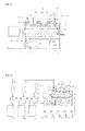
- FIG. 2 is a longitudinal sectional view of the continuous reactor shown in FIG. 1 .
- an all-in-one type continuous reactor (hereinafter abbreviated as "reactor") according to the present invention generally comprises: a non-rotating cylinder 10 having a reaction chamber 11 therein; a stirring motor 20 disposed at one side of the cylinder 10; and a stirring rod 30 coupled to a motor shaft 21 of the stirring motor 20 and included in the reaction chamber 11 so as to be spaced from the wall surface of the reaction chamber 11.
- the reactor of the present invention further comprises: a flange unit 12 provided at one side of the cylinder 10; a reactant inlet port 13 provided on the flange unit so as to communicate with the reaction chamber 11 and configured to introduce a reactant into the reaction chamber; and a reaction product outlet port 14 provided at the other side of the cylinder 10 so as to communicate with the reaction chamber 11 and configured to discharge a reaction product from the reaction chamber.
- a plurality of the reactant inlet port 13 may be radially arranged along the outer circumference of the flange unit 12.
- Reference numeral 11a indicates a reactant drain port serving to clean a reactant from the reactor when cleaning the reactor.
- a plurality of the flange units 12 may also be provided on the outer circumference of the cylinder 10 at a predetermined distance from each other, and each of the flange units 12 may have the reactant inlet port 13.
- This configuration enables different reactants to be introduced through the reactant inlet ports 13 of the flange units 12.
- the mixing rate of the reactants that are introduced through the reactant inlet port 13 is lower in the direction of the stirring rod 30 and higher in the radial direction.
- ring-shaped Taylor vortices are formed which rotate in opposite directions in the direction of the stirring rod 30. This Taylor flow can be easily generated by changing the rotating speed of the stirring rod, and thus the stability of the fluid can be used.
- the stirring motor 20 is a speed-changeable stirring motor whose rotating speed can be controlled in the range from 10 to 2000 rpm.
- the rotating speed of the stirring rod 30 connected directly thereto can also be changed in the above range to cause vortices in the reactant.
- the ratio of the gap (g) between the inner circumferential surface of the reaction chamber 11 and the outer circumferential surface of the stirring rod 30 to the radius (d) of the stirring rod 30, that is, g/d, is preferably 1.0 or smaller. If the ratio is greater than 1.0, vortices in the reactant flowing in the reaction chamber 11 will not be generated or will be insufficient, and thus stirring of the reactant will be insufficient.
- a plurality of extra ports may be provided so as to communicate with the reaction chamber 11.
- the extra ports can be used for various purposes, and for example, the extra ports can be used as reactant inlet ports, or a flow rate sensor as described below can be placed in the extra ports, or the reactant can be sampled through the extra ports, or the extra ports may also be closed with a blocking plate.
- the reactor of the present invention may further comprise a temperature control unit 40 disposed in the wall portion of the cylinder 10.
- the temperature control unit 40 serves to increase or reduce the temperature of the reactant.
- the temperature control unit 40 may comprise a ring-shaped refrigerant chamber 41 formed in the wall portion of the cylinder 10 so as to surround the reaction chamber 11, and a high-temperature or low-temperature refrigerant 42 filled in the refrigerant chamber 41.
- the temperature control unit 40 may also comprise a spirally wound heating tube (not shown) placed in the cylinder 10 and a refrigerant filled in the wound heating tube.
- the temperature control unit 40 may serve to control the temperature of the reactant in the temperature ranging from room temperature to about 80 ⁇ 1 °C.
- the refrigerant chamber 41 may be divided into a plurality of regions by a barrier 41c as shown in FIG. 2 in order to control the temperature of the reactant in each of the divided regions.
- Reference numeral 41a indicates a refrigerant inlet port
- reference numeral 41b indicates a refrigerant outlet port.
- the reactor of the present invention may further comprise a pulverizing unit 50 provided in the reactant inlet port 13 and configured to pulverize particles of the reactant that is introduced through the reactant inlet port 13.
- the pulverizing unit may, for example, be an ultrasonic pulverizer.
- a frequency voltage of 50-60 Hz is converted to high-frequency electrical energy of 20 kHz or higher in a generator, and the high-frequency electrical energy is converted into mechanical vibrations by a piezoelectric ceramic material in a convertor, and this conversion is referred to as inverse piezoelectric effect.
- the resulting vertical vibrations are transferred to a liquid sample.
- the reactor of the present invention may further comprise a flow rate sensor 60 provided in at least one of the reactant inlet port 13, the reaction product outlet port 14 and the extra ports 15 and configured to sense the flow rate of the reactant.
- the reactor of the present invention may further comprise a flow rate control unit 70 configured to control either the flow rate of the reactant that is introduced through the reactant inlet port 13 or the flow rate of the reactant passing through the reaction chamber 11 or the flow rate of the reaction product that is discharged through the reaction product outlet port 14, based on flow rate data sensed by the flow rate sensor 60.
- the flow rate of the reactant passing through the reactor can be controlled according to the user's intention, and the flow rate can be maintained at a constant level.
- the reactor of the present invention is supported by a plate-shaped first supporter 80 and second supporter 80a at the side of the cylinder 10 where the stirring motor 10 is disposed and the side opposite thereto.
- the first supporter 80 consists of a support panel 81 and a roller 82 provided at the bottom of the support panel 81.
- the reactor of the present invention can be conveniently moved using the roller 82.
- the inventive reactor as described above may contain a metal solution (containing Ni, Mn and Co), NH 4 OH and NaOH as reactants for preparing a positive electrode active material for a lithium secondary battery.
- the reactor may contain lithium hydroxide LiOH, ferrous sulfate (FeSO 4 ) and phosphoric acid (H 3 PO 4 ). When these reactants are allowed to react with each other in the reactor, a precursor of a positive electrode active material for a lithium secondary battery is obtained.
- a crystal separation apparatus comprises the reactor of the present invention.
- the crystal separation apparatus comprises a plurality of reactant storage tanks 100 connected by connection lines L1, L2 and L3 to a plurality of reactant inlet ports 13 provided on the flange unit 12 of the reactor.
- the reactant storage tanks 100 are configured to store the metal solution (that is a mixture containing Ni, Mn and Co), NH 4 , OH and NaOH.
- the crystal separation apparatus comprises supply pumps 200 provided in the connection lines L1, L2 and L3, respectively, and configured to introduce reactants from the reactant storage tanks 100 into the reaction chamber 11 of the continuous reactor by pumping.
- the supply pumps 200 have a pump pressure of 2 bar or higher and may be pulseless pumps whose pumping flow rate does not change even when being used for a long period.
- the crystal separation apparatus may further comprise a positive electrode active material separator 300 connected with a reaction product outlet port of the continuous reactor and configured to separate a slurry-type reaction product, which is discharged through the outlet port 14, into the positive electrode active material and a liquid.
- the positive electrode active material separator may be a centrifuge or a dehydrator.
- the crystal separation apparatus may further comprise a dryer 400 and a particle size analyzer 500 provided following the dryer 400 and configured to analyze the particle size distribution and particle size of the dried positive electrode active material.
- the crystal separation apparatus may further comprise a scanning electron microscope 600 provided following the particle size analyzer 500 and configured to analyze the particle shape and particle size uniformity of the positive electrode active material.
- the scanning electron microscope 600 is used to observe a sample by detecting secondary electrons or back scattered electrons among various signals that are generated when an electron beam is scanned across the sample surface.
- the crystal separation apparatus may further comprise a dryer 400 connected with the positive electrode active material separator 300 and configured to dry the positive electrode active material separated by the positive electrode active material separator 300.
Abstract
Description
- The present invention relates to an all-in-one type continuous reactor for preparing a positive electrode active material for a lithium secondary battery and to a crystal separation apparatus comprising the same.
- More particularly, the present invention relates to an all-in-one type continuous reactor for preparing a positive electrode active material for a lithium secondary battery, wherein a temperature control unit, a particle size control unit and a flow rate control unit are integrally provided so that a series of processes for obtaining a high-purity reaction product can be carried in the reactor, and to a crystal separation apparatus comprising the reactor.
- Reactors are devices in which two or more different materials are allowed to react with each other at a certain temperature and pressure in the presence of catalysts or the like to produce a product having a composition and structure different from those of the reactants. The reactors are classified into a continuous reactor and a batch-type reactor.
- The continuous reactor is a device in which introduced reactants react with each other while flowing through the reactor and the reaction product is discharged through an outlet, and the batch-type reactor is a device in which introduced reactants react with each other in a non-flowing state and the reaction product is recovered from the reactor.
- Conventional continuous reactors have an advantage in that a product is recovered at a high rate. However, these reactors do not have means capable of controlling the size of the reaction product, and for this reason, in order to reduce or increase the size of the reaction product crystal, the reaction product should be further reacted in an additional device. Thus, these have disadvantages in terms of space and time.
- In addition, conventional continuous reactors do not have a control unit for precisely controlling the amount of reaction solutions, and thus it is difficult for these reactors to precisely control the reaction solutions. For this reason, it is difficult for these rectors to achieve an accurate reaction, and thus the reaction product has low reliability.
- Accordingly, the present invention has been in order to solve the above-described problems occurring in the prior art, and an object of the present invention is to provide an all-in-one type continuous reactor for preparing a positive electrode active material for a lithium secondary battery, wherein a temperature control unit, a particle size control unit and a flow rate control unit are integrally provided so that a series of processes for obtaining a high-purity reaction product (positive electrode active material) can be carried out in the reactor, and a crystal separation apparatus comprising the reactor.
- In order to accomplish the above object, in a first aspect, the present invention provides an all-in-one type continuous reactor for preparing a positive electrode active material for a lithium secondary battery, the continuous reactor comprising: a
non-rotating cylinder 10 having areaction chamber 11 therein; astirring motor 20 disposed at one side of thecylinder 10; astirring rod 30 coupled to amotor shaft 21 of the stirringmotor 20 and included in thereaction chamber 11 so as to be spaced from the wall surface of thereaction chamber 11; aflange unit 12 provided at one side of thecylinder 10; at least onereactant inlet port 13 provided on the flange unit so as to communicate with thereaction chamber 11 and configured to introduce a reactant into the reaction chamber; a reactionproduct outlet port 14 provided at the other side of thecylinder 10 so as to communicate with thereaction chamber 11 and configured to discharge a reaction product from the reaction chamber; a plurality ofextra ports 15 provided between thereactant inlet port 13 and the reactionproduct outlet port 14 so as to communicate with thereaction chamber 11; atemperature control unit 40 disposed between the inner circumferential surface and outercircumferential surface 10, thetemperature control unit 40 comprising a ring-shaped refrigerant chamber 41 and arefrigerant 42 filled in the refrigerant chamber; a pulverizingunit 50 provided in thereactant inlet port 13 and configured to pulverize particles of the reactant that is introduced through the reactant inlet port; aflow rate sensor 60 provided in at least one of thereactant inlet port 13, the reactionproduct outlet port 14 and theextra ports 15 and configured to sense the flow rate of the reactant; and a flowrate control unit 70 configured to control the flow rate of the reactant, which is introduced through thereactant inlet port 13, on the basis of flow rate data sensed by theflow rate sensor 60. - In a second aspect, the present invention provides an all-in-one type continuous reactor for preparing a positive electrode active material for a lithium secondary battery, the continuous reactor comprising: a
non-rotating cylinder 10 having areaction chamber 11 therein; astirring motor 20 disposed at one side of thecylinder 10; astirring rod 30 coupled to amotor shaft 21 of the stirringmotor 20 and included in thereaction chamber 11 so as to be spaced from the wall surface of thereaction chamber 11; a plurality offlange units 12 provided on thecylinder 10 so as to be spaced from each other; at least onereactant inlet port 13 provided on each of the flange units so as to communicate with thereaction chamber 11 and configured to introduce a reactant into the reaction chamber; a reactionproduct outlet port 14 provided at the other side of thecylinder 10 so as to communicate with thereaction chamber 11 and configured to discharge a reaction product from the reaction chamber; a plurality ofextra ports 15 provided between thereactant inlet port 13 and the reactionproduct outlet port 14 so as to communicate with thereaction chamber 11; atemperature control unit 40 disposed between the inner circumferential surface and outercircumferential surface 10, thetemperature control unit 40 comprising a ring-shaped refrigerant chamber 41 and arefrigerant 42 filled in the refrigerant chamber; a pulverizingunit 50 provided in thereactant inlet port 13 and configured to pulverize particles of the reactant that is introduced through the reactant inlet port; aflow rate sensor 60 provided in at least one of thereactant inlet port 13, the reactionproduct outlet port 14 and theextra ports 15 and configured to sense the flow rate of the reactant; and a flowrate control unit 70 configured to control the flow rate of the reactant, which is introduced through thereactant inlet port 13, on the basis of flow rate data sensed by theflow rate sensor 60. - In a third aspect, the present invention provides a crystal separation apparatus comprising: an all-in-one type continuous reactor as described above; a plurality of
reactant storage tanks 100 connected by connection lines L1, L2 and L3 to a plurality ofreactant inlet ports 13 provided on aflange unit 12 of the continuous reactor;supply pumps 200 provided in the connection lines L1, L2 and L3, respectively, and configured to introduce reactants from thereactant storage tanks 100 into areaction chamber 11 of the continuous reactor by pumping; a positive electrodeactive material separator 300 connected with a reaction product outlet port of the continuous reactor and configured to separate a slurry-type reaction product, which is discharged through theoutlet port 14, into the positive electrode active material and a liquid; and adryer 400 connected with the positive electrodeactive material separator 300 and configured to dry the positive electrode active material separated by the positive electrodeactive material separator 300. - According to the present invention, a temperature control unit, a particle size control unit and a flow ate control unit are integrally provided in a single reactor so that a series of processes for obtaining a high-purity reaction product can be the reactor. Thus, the reactor according to the present invention is efficient and cost-effective.
-
-
FIG. 1 is a perspective view of an all-in-one type continuous reactor according to a first embodiment of the present invention. -
FIG. 2 is a longitudinal sectional view of the continuous reactor shown inFIG. 1 . -
FIG. 3 is a perspective view of an all-in-one type continuous reactor according to a second embodiment of the present invention. -
FIG. 4 shows the configuration of a crystal separation apparatus according to the present invention. - Hereinafter, embodiments according to the present invention will be described. In the following description, like reference numerals indicate like elements, and an overlapping description of components or an additional description causing the scope of the present invention to be construed in a limited sense will be omitted.
- The disclosed embodiments are provided to enable those skilled in the art to easily understand the present invention and are not intended to limit the scope of the present invention. The embodiments of the present invention may be modified into other forms within the technical idea and scope of the present invention. As used herein, the term "and/or" is meant to include at least one of components listed before and after the term "and/or". When one element is referred to as being on another element, it can be directly on the other element or intervening elements may be present therebetween. Although the terms "first", "second", etc. may be used herein to clearly express various elements, these elements should not be limited by these terms. The thickness and relative thickness of elements shown in the figures may be exaggerated in order to clearly describe the embodiments of the present invention. In addition, features shown in the figures are shown to easily describe the embodiments of the present invention and may differ from actual features.
-
FIG. 1 is a perspective view of an all-in-one type continuous reactor according to a first embodiment of the present invention, andFIG. 2 is a longitudinal sectional view of the continuous reactor shown inFIG. 1 . - Referring to
FIGS. 1 and 2 , an all-in-one type continuous reactor (hereinafter abbreviated as "reactor") according to the present invention generally comprises: anon-rotating cylinder 10 having areaction chamber 11 therein; astirring motor 20 disposed at one side of thecylinder 10; and astirring rod 30 coupled to amotor shaft 21 of the stirringmotor 20 and included in thereaction chamber 11 so as to be spaced from the wall surface of thereaction chamber 11. - In addition, the reactor of the present invention further comprises: a
flange unit 12 provided at one side of thecylinder 10; areactant inlet port 13 provided on the flange unit so as to communicate with thereaction chamber 11 and configured to introduce a reactant into the reaction chamber; and a reactionproduct outlet port 14 provided at the other side of thecylinder 10 so as to communicate with thereaction chamber 11 and configured to discharge a reaction product from the reaction chamber. - Herein, a plurality of the
reactant inlet port 13 may be radially arranged along the outer circumference of theflange unit 12. -
Reference numeral 11a indicates a reactant drain port serving to clean a reactant from the reactor when cleaning the reactor. - As shown in
FIG. 3 , in the reactor of the present invention, a plurality of theflange units 12 may also be provided on the outer circumference of thecylinder 10 at a predetermined distance from each other, and each of theflange units 12 may have thereactant inlet port 13. This configuration enables different reactants to be introduced through thereactant inlet ports 13 of theflange units 12. When thestirring rod 30 is rotated, the mixing rate of the reactants that are introduced through thereactant inlet port 13 is lower in the direction of thestirring rod 30 and higher in the radial direction. Thus, when there is a flow in the direction of the stirringrod 30, mixing between cells occurs, but a fluid near the stirringrod 30 tends to move toward the inner wall of thecylinder 10 fixed by the centrifugal force. Due to this unstable fluid, ring-shaped Taylor vortices are formed which rotate in opposite directions in the direction of thestirring rod 30. This Taylor flow can be easily generated by changing the rotating speed of the stirring rod, and thus the stability of the fluid can be used. - The stirring
motor 20 is a speed-changeable stirring motor whose rotating speed can be controlled in the range from 10 to 2000 rpm. Thus, the rotating speed of the stirringrod 30 connected directly thereto can also be changed in the above range to cause vortices in the reactant. - The ratio of the gap (g) between the inner circumferential surface of the
reaction chamber 11 and the outer circumferential surface of thestirring rod 30 to the radius (d) of thestirring rod 30, that is, g/d, is preferably 1.0 or smaller. If the ratio is greater than 1.0, vortices in the reactant flowing in thereaction chamber 11 will not be generated or will be insufficient, and thus stirring of the reactant will be insufficient. - Between the
reactant inlet port 13 of thecylinder 10 and the reactionproduct outlet port 14, a plurality of extra ports may be provided so as to communicate with thereaction chamber 11. The extra ports can be used for various purposes, and for example, the extra ports can be used as reactant inlet ports, or a flow rate sensor as described below can be placed in the extra ports, or the reactant can be sampled through the extra ports, or the extra ports may also be closed with a blocking plate. - In addition, the reactor of the present invention may further comprise a
temperature control unit 40 disposed in the wall portion of thecylinder 10. Thetemperature control unit 40 serves to increase or reduce the temperature of the reactant. In an embodiment of the present invention, thetemperature control unit 40 may comprise a ring-shaped refrigerant chamber 41 formed in the wall portion of thecylinder 10 so as to surround thereaction chamber 11, and a high-temperature or low-temperature refrigerant 42 filled in therefrigerant chamber 41. In another embodiment of the present invention, thetemperature control unit 40 may also comprise a spirally wound heating tube (not shown) placed in thecylinder 10 and a refrigerant filled in the wound heating tube. Herein, thetemperature control unit 40 may serve to control the temperature of the reactant in the temperature ranging from room temperature to about 80 ±1 °C. - Herein, the
refrigerant chamber 41 may be divided into a plurality of regions by abarrier 41c as shown inFIG. 2 in order to control the temperature of the reactant in each of the divided regions. -
Reference numeral 41a indicates a refrigerant inlet port, andreference numeral 41b indicates a refrigerant outlet port. - In addition, the reactor of the present invention may further comprise a pulverizing
unit 50 provided in thereactant inlet port 13 and configured to pulverize particles of the reactant that is introduced through thereactant inlet port 13. The pulverizing unit may, for example, be an ultrasonic pulverizer. For reference, in the ultrasonic pulverizer, a frequency voltage of 50-60 Hz is converted to high-frequency electrical energy of 20 kHz or higher in a generator, and the high-frequency electrical energy is converted into mechanical vibrations by a piezoelectric ceramic material in a convertor, and this conversion is referred to as inverse piezoelectric effect. The resulting vertical vibrations are transferred to a liquid sample. Due to constant amplitude and at least 20,000 vibrations/sec of a probe (or tip) that transfers the ultrasonic vertical vibrations to the liquid sample, expansion (negative pressure) and shrinkage (positive pressure) occur in the sample, and microscopic bubbles generated in this expansion/shrinkage process are intensively collapsed during expansion. This is referred to as cavitation (the rapid formation and collapse of microscopic bubbles in a liquid). At this time, shock waves having a pressure of about 1000 bar and an instantaneous temperature of about 5000 K are generated, and these waves act as a very high energy source to pulverize sample particles. - In addition, the reactor of the present invention may further comprise a
flow rate sensor 60 provided in at least one of thereactant inlet port 13, the reactionproduct outlet port 14 and theextra ports 15 and configured to sense the flow rate of the reactant. Additionally, the reactor of the present invention may further comprise a flowrate control unit 70 configured to control either the flow rate of the reactant that is introduced through thereactant inlet port 13 or the flow rate of the reactant passing through thereaction chamber 11 or the flow rate of the reaction product that is discharged through the reactionproduct outlet port 14, based on flow rate data sensed by theflow rate sensor 60. - By means of the
flow rate sensor 60 and the flowrate control unit 70, the flow rate of the reactant passing through the reactor can be controlled according to the user's intention, and the flow rate can be maintained at a constant level. - The reactor of the present invention is supported by a plate-shaped
first supporter 80 andsecond supporter 80a at the side of thecylinder 10 where the stirringmotor 10 is disposed and the side opposite thereto. Herein, thefirst supporter 80 consists of asupport panel 81 and a roller 82 provided at the bottom of thesupport panel 81. Thus, the reactor of the present invention can be conveniently moved using the roller 82. - The inventive reactor as described above may contain a metal solution (containing Ni, Mn and Co), NH4OH and NaOH as reactants for preparing a positive electrode active material for a lithium secondary battery. Alternatively, the reactor may contain lithium hydroxide LiOH, ferrous sulfate (FeSO4) and phosphoric acid (H3PO4). When these reactants are allowed to react with each other in the reactor, a precursor of a positive electrode active material for a lithium secondary battery is obtained.
- Meanwhile, a crystal separation apparatus according to the present invention comprises the reactor of the present invention.
- In addition, the crystal separation apparatus according to the present invention comprises a plurality of
reactant storage tanks 100 connected by connection lines L1, L2 and L3 to a plurality ofreactant inlet ports 13 provided on theflange unit 12 of the reactor. Herein, thereactant storage tanks 100 are configured to store the metal solution (that is a mixture containing Ni, Mn and Co), NH4, OH and NaOH. - In addition, the crystal separation apparatus according to the present invention comprises supply pumps 200 provided in the connection lines L1, L2 and L3, respectively, and configured to introduce reactants from the
reactant storage tanks 100 into thereaction chamber 11 of the continuous reactor by pumping. The supply pumps 200 have a pump pressure of 2 bar or higher and may be pulseless pumps whose pumping flow rate does not change even when being used for a long period. - In addition, the crystal separation apparatus according to the present invention may further comprise a positive electrode
active material separator 300 connected with a reaction product outlet port of the continuous reactor and configured to separate a slurry-type reaction product, which is discharged through theoutlet port 14, into the positive electrode active material and a liquid. Herein, the positive electrode active material separator may be a centrifuge or a dehydrator. - In addition, the crystal separation apparatus according to the present invention may further comprise a
dryer 400 and aparticle size analyzer 500 provided following thedryer 400 and configured to analyze the particle size distribution and particle size of the dried positive electrode active material. - In addition, the crystal separation apparatus according to the present invention may further comprise a
scanning electron microscope 600 provided following theparticle size analyzer 500 and configured to analyze the particle shape and particle size uniformity of the positive electrode active material. Herein, thescanning electron microscope 600 is used to observe a sample by detecting secondary electrons or back scattered electrons among various signals that are generated when an electron beam is scanned across the sample surface. - In addition, the crystal separation apparatus according to the present invention may further comprise a
dryer 400 connected with the positive electrodeactive material separator 300 and configured to dry the positive electrode active material separated by the positive electrodeactive material separator 300. - Although the preferred embodiments of the present invention have been disclosed for illustrative purposes, those skilled in the art will appreciate that various modifications, additions and substitutions are possible, without departing from the scope and spirit of the invention as disclosed in the accompanying claims.
Claims (12)
- An all-in-one type continuous reactor for preparing a positive electrode active material for a lithium secondary battery, the continuous reactor comprising:a non-rotating cylinder 10 having a reaction chamber 11 therein;a stirring motor 20 disposed at one side of the cylinder 10;a stirring rod 30 coupled to a motor shaft 21 of the stirring motor 20 and included in the reaction chamber 11 so as to be spaced from the wall surface of the reaction chamber 11;a flange unit 12 provided at one side of the cylinder 10;at least one reactant inlet port 13 provided on the flange unit so as to communicate with the reaction chamber 11 and configured to introduce a reactant into the reaction chamber;a reaction product outlet port 14 provided at the other side of the cylinder 10 so as to communicate with the reaction chamber 11 and configured to discharge a reaction product from the reaction chamber;a plurality of extra ports 15 provided between the reactant inlet port 13 and the reaction product outlet port 14 so as to communicate with the reaction chamber 11;a temperature control unit 40 disposed between the inner circumferential surface and outer circumferential surface 10, the temperature control unit 40 comprising a ring-shaped refrigerant chamber 41 and a refrigerant filled in the refrigerant chamber;a pulverizing unit 50 provided in the reactant inlet port 13 and configured to pulverize particles of the reactant that is introduced through the reactant inlet port;a flow rate sensor 60 provided in at least one of the reactant inlet port 13, the reaction product outlet port 14 and the extra ports 15 and configured to sense the flow rate of the reactant; anda flow rate control unit 70 configured to control the flow rate of the reactant, which is introduced through the reactant inlet port 13, on the basis of flow rate data sensed by the flow rate sensor 60.
- The all-in-one type continuous reactor of claim 1, wherein the stirring motor 20 is a speed-changeable stirring motor whose rotating speed is changeable in the range of 10 to 2000 rpm.
- The all-in-one type continuous reactor of claim 1, wherein the reactant comprises a metal solution, NH4OH and NaOH.
- The all-in-one type continuous reactor of claim 3, wherein the metal solution is a mixture solution containing Ni, Mn and Co.
- The all-in-one type continuous reactor of claim 1, wherein the reactant comprises LiOH, FeSO4 and H3PO4.
- The all-in-one type continuous reactor of claim 1, wherein the ratio of the gap (g) between the inner circumferential surface of the reaction chamber 11 and the outer circumferential surface of the stirring rod 30 to the radius (d) of the stirring rod 30 is 1.0 or smaller.
- An all-in-one type continuous reactor for preparing a positive electrode active material for a lithium secondary battery, the continuous reactor comprising:a non-rotating cylinder 10 having a reaction chamber 11 therein;a stirring motor 20 disposed at one side of the cylinder 10;a stirring rod 30 coupled to a motor shaft 21 of the stirring motor 20 and included in the reaction chamber 11 so as to be spaced from the wall surface of the reaction chamber 11;a plurality of flange units 12 provided on the cylinder 10 so as to be spaced from each other;at least one reactant inlet port 13 provided on each of the flange units so as to communicate with the reaction chamber 11 and configured to introduce a reactant into the reaction chamber;a reaction product outlet port 14 provided at the other side of the cylinder 10 so as to communicate with the reaction chamber 11 and configured to discharge a reaction product from the reaction chamber;a plurality of extra ports 15 provided between the reactant inlet port 13 and the reaction product outlet port 14 so as to communicate with the reaction chamber 11;a temperature control unit 40 disposed between the inner circumferential surface and outer circumferential surface 10, the temperature control unit 40 comprising a ring-shaped refrigerant chamber 41 and a refrigerant 42 filled in the refrigerant chamber;a pulverizing unit 50 provided in the reactant inlet port 13 and configured to pulverize particles of the reactant that is introduced through the reactant inlet port;a flow rate sensor 60 provided in at least one of the reactant inlet port 13, the reaction product outlet port 14 and the extra ports 15 and configured to sense the flow rate of the reactant; anda flow rate control unit 70 configured to control the flow rate of the reactant, which is introduced through the reactant inlet port 13, on the basis of flow rate data sensed by the flow rate sensor 60.
- A crystal separation apparatus comprising:an all-in-one type continuous reactor according to any one of claims 1 to 6;a plurality of reactant storage tanks 100 connected by connection lines L1, L2 and L3 to a plurality of reactant inlet ports 13 provided on a flange unit 12 of the continuous reactor;supply pumps 200 provided in the connection lines L1, L2 and L3, respectively, and configured to introduce reactants from the reactant storage tanks 100 into a reaction chamber 11 of the continuous reactor by pumping;a positive electrode active material separator 300 connected with a reaction product outlet port of the continuous reactor and configured to separate a slurry-type reaction product, which is discharged through the outlet port 14, into the positive electrode active material and a solution; anda dryer 400 connected with the positive electrode active material separator 300 and configured to dry the positive electrode active material separated by the positive electrode active material separator 300.
- The crystal separation apparatus of claim 8, wherein the positive electrode active material separator 300 is a centrifuge or a dehydrator.
- The crystal separation apparatus of claim 8, further comprising a particle size analyzer 500 provided following the dryer 400 and configured to analyze the particle size distribution and particle size of the active electrode active material dried by the dryer.
- The crystal separation apparatus of claim 10, further comprising a scanning electron microscope 600 provided following the particle size analyzer 500 and configured to analyze the particle shape and particle size uniformity of the active electrode active material.
- The crystal separation apparatus of claim 11, further comprising a densitometer 700 provided following the scanning electron microscope 600 and configured to measure the density of the active electrode active material.
Applications Claiming Priority (2)
| Application Number | Priority Date | Filing Date | Title |
|---|---|---|---|
| KR1020110071775A KR101092337B1 (en) | 2011-07-20 | 2011-07-20 | Lithium battery cathode materials for manufacturing an all-in-one type of continuous reactor, and it determines the separation device that includes |
| PCT/KR2012/000380 WO2013012147A1 (en) | 2011-07-20 | 2012-01-17 | All-in-one-type continuous reactor for manufacturing a positive electrode active material for a lithium secondary battery, and crystal separation apparatus comprising same |
Publications (3)
| Publication Number | Publication Date |
|---|---|
| EP2735366A1 true EP2735366A1 (en) | 2014-05-28 |
| EP2735366A4 EP2735366A4 (en) | 2015-11-25 |
| EP2735366B1 EP2735366B1 (en) | 2019-09-11 |
Family
ID=45506033
Family Applications (1)
| Application Number | Title | Priority Date | Filing Date |
|---|---|---|---|
| EP12815539.7A Active EP2735366B1 (en) | 2011-07-20 | 2012-01-17 | All-in-one-type continuous reactor for manufacturing a positive electrode active material for a lithium secondary battery, and crystal separation apparatus comprising same |
Country Status (5)
| Country | Link |
|---|---|
| US (1) | US10010851B2 (en) |
| EP (1) | EP2735366B1 (en) |
| JP (1) | JP5714708B2 (en) |
| KR (1) | KR101092337B1 (en) |
| WO (1) | WO2013012147A1 (en) |
Cited By (5)
| Publication number | Priority date | Publication date | Assignee | Title |
|---|---|---|---|---|
| EP2910300A4 (en) * | 2012-11-27 | 2016-07-27 | Laminar Co Ltd | Reaction device for mixing and manufacturing method using the reaction device |
| EP3012019A4 (en) * | 2013-06-17 | 2016-12-21 | Laminar Co Ltd | Particle production device and particle production method using same |
| EP3010074A4 (en) * | 2013-06-14 | 2017-01-04 | Laminar Co., Ltd. | Device for preparing core-shell particles and method for preparing core-shell particles by using same |
| EP3385227A1 (en) * | 2017-04-04 | 2018-10-10 | Laminar Co., Ltd. | Manufacturing method of cathode active material for secondary cell |
| EP3776699A4 (en) * | 2018-04-13 | 2021-09-01 | Wirtz Manufacturing Co., Inc. | Battery paste mixer and method |
Families Citing this family (10)
| Publication number | Priority date | Publication date | Assignee | Title |
|---|---|---|---|---|
| WO2013115446A1 (en) | 2012-02-01 | 2013-08-08 | 주식회사 엘지화학 | Reactor for preparing precursor of lithium composite transition metal oxide, and method for preparing precursor |
| KR101361118B1 (en) * | 2012-03-08 | 2014-02-13 | 주식회사 라미나 | Gas-liquid reactor using lithium secondary battery cathode active material, method of manufacture |
| KR101399057B1 (en) | 2012-11-27 | 2014-05-27 | 주식회사 라미나 | Solid - liquid substances mixed reaction apparatus |
| KR101536297B1 (en) * | 2012-12-24 | 2015-07-14 | 주식회사 포스코 | Manufacturing of positive active material precursor for secondary battery |
| KR102097584B1 (en) * | 2018-05-04 | 2020-04-06 | 재단법인 차세대융합기술연구원 | Taylor reactor |
| KR102314019B1 (en) * | 2019-12-20 | 2021-10-15 | 주식회사 포스코 | A method for controlling the size of lituim peroxide and a method for preparing lithium oxide with controlled size |
| JP7155360B1 (en) * | 2021-08-02 | 2022-10-18 | 株式会社日本製鋼所 | Reactor, reaction system, material manufacturing system, battery material manufacturing system, battery manufacturing system, reaction product manufacturing method, battery material manufacturing method, and battery manufacturing method |
| CN113889614B (en) * | 2021-09-30 | 2023-03-14 | 长兴浙力新材料有限公司 | Production process of lithium battery anode raw material |
| JP2023181867A (en) * | 2022-06-13 | 2023-12-25 | 株式会社日本製鋼所 | Reaction system and cleaning method |
| KR20240037680A (en) * | 2022-09-15 | 2024-03-22 | 주식회사 엘지화학 | Preparing method of precusor for positive electrode active material |
Family Cites Families (17)
| Publication number | Priority date | Publication date | Assignee | Title |
|---|---|---|---|---|
| US3744926A (en) * | 1972-05-22 | 1973-07-10 | J Hedges | Rotary engine |
| FI863926A (en) * | 1985-09-30 | 1987-03-31 | Union Carbide Corp | BEHANDLING AV VATTENSYSTEM MED SYNERGISTISKA ALGDOEDANDE BLANDNINGAR. |
| ATE111769T1 (en) * | 1990-07-20 | 1994-10-15 | Dow Chemical Co | PROCESSES FOR THE CONTINUOUS PRODUCTION OF REACTION PRODUCTS. |
| JPH1025117A (en) * | 1996-07-09 | 1998-01-27 | Japan Metals & Chem Co Ltd | Production of nickel hydroxide |
| US6471392B1 (en) * | 2001-03-07 | 2002-10-29 | Holl Technologies Company | Methods and apparatus for materials processing |
| KR20020021760A (en) * | 2000-09-16 | 2002-03-22 | 강경석 | Continuous system and its operating method for producing polyolefin wax using horizontal thermal-cracking reactor |
| US6589299B2 (en) * | 2001-02-13 | 2003-07-08 | 3M Innovative Properties Company | Method for making electrode |
| JP5069827B2 (en) * | 2001-02-28 | 2012-11-07 | 株式会社ダイセル | Reaction control method and control apparatus |
| KR100759456B1 (en) | 2001-06-22 | 2007-10-04 | 삼성에스디아이 주식회사 | Positive active material for lithium rechargeable battery and method of preparing same |
| JP4404961B2 (en) * | 2002-01-08 | 2010-01-27 | 双葉電子工業株式会社 | A method for producing carbon nanofibers. |
| KR100548988B1 (en) * | 2003-11-26 | 2006-02-02 | 학교법인 한양학원 | Manufacturing process of cathodes materials of lithium second battery, the reactor used therein and cathodes materials of lithium second battery manufactured thereby |
| US20070025889A1 (en) * | 2005-07-28 | 2007-02-01 | Pcbu Business Services, Inc. | Reactors, reactor assemblies and production processes |
| JP2007085650A (en) * | 2005-09-22 | 2007-04-05 | Sharp Corp | Heat exchanger, stirling engine attached therewith, and manufacturing method thereof |
| KR100796687B1 (en) | 2005-11-30 | 2008-01-21 | 삼성에스디아이 주식회사 | Active material for rechargeable lithium battery, method of preparing thereof and rechargeable lithium battery comprising same |
| CN101374883B (en) * | 2006-01-30 | 2011-06-29 | 株式会社吴羽 | Process for producing aliphatic polyester |
| JP5633742B2 (en) * | 2008-10-23 | 2014-12-03 | 独立行政法人科学技術振興機構 | Concentrated acid treatment section, concentrated acid treatment method, plant resource phase separation system conversion device and conversion method |
| JP2012136421A (en) * | 2010-12-09 | 2012-07-19 | Sumitomo Chemical Co Ltd | Method for producing transition metal hydroxide |
-
2011
- 2011-07-20 KR KR1020110071775A patent/KR101092337B1/en active IP Right Grant
-
2012
- 2012-01-17 US US14/129,112 patent/US10010851B2/en active Active
- 2012-01-17 EP EP12815539.7A patent/EP2735366B1/en active Active
- 2012-01-17 WO PCT/KR2012/000380 patent/WO2013012147A1/en active Application Filing
- 2012-01-17 JP JP2013525854A patent/JP5714708B2/en active Active
Cited By (6)
| Publication number | Priority date | Publication date | Assignee | Title |
|---|---|---|---|---|
| EP2910300A4 (en) * | 2012-11-27 | 2016-07-27 | Laminar Co Ltd | Reaction device for mixing and manufacturing method using the reaction device |
| EP3010074A4 (en) * | 2013-06-14 | 2017-01-04 | Laminar Co., Ltd. | Device for preparing core-shell particles and method for preparing core-shell particles by using same |
| US10601035B2 (en) | 2013-06-14 | 2020-03-24 | Posco | Method of preparing core-shell particles |
| EP3012019A4 (en) * | 2013-06-17 | 2016-12-21 | Laminar Co Ltd | Particle production device and particle production method using same |
| EP3385227A1 (en) * | 2017-04-04 | 2018-10-10 | Laminar Co., Ltd. | Manufacturing method of cathode active material for secondary cell |
| EP3776699A4 (en) * | 2018-04-13 | 2021-09-01 | Wirtz Manufacturing Co., Inc. | Battery paste mixer and method |
Also Published As
| Publication number | Publication date |
|---|---|
| EP2735366A4 (en) | 2015-11-25 |
| US20140147338A1 (en) | 2014-05-29 |
| KR101092337B1 (en) | 2011-12-09 |
| JP5714708B2 (en) | 2015-05-07 |
| US10010851B2 (en) | 2018-07-03 |
| EP2735366B1 (en) | 2019-09-11 |
| JP2013539176A (en) | 2013-10-17 |
| WO2013012147A1 (en) | 2013-01-24 |
Similar Documents
| Publication | Publication Date | Title |
|---|---|---|
| EP2735366B1 (en) | All-in-one-type continuous reactor for manufacturing a positive electrode active material for a lithium secondary battery, and crystal separation apparatus comprising same | |
| WO2012000351A1 (en) | Ultrasonic mixing equipment | |
| US10201797B2 (en) | Reaction device for mixing and manufacturing method using the reaction device | |
| US10601035B2 (en) | Method of preparing core-shell particles | |
| US20130186970A1 (en) | Shearing disperser, circulation-type dispersing system, and circulation-type dispersing method | |
| RU2009140402A (en) | DEVICE FOR PROCESSING WATER BALLAST WITH AQUEOUS SOLUTION ACROLEIN | |
| CN103028360B (en) | Shearing device for stirring reactor and stirring reactor | |
| CN205730451U (en) | Chinese crude drug constituents extraction unit | |
| CN109351217B (en) | Ultrasonic emulsification device for preparing pesticide microcapsules | |
| CN202527176U (en) | Device for preparing micro-nano powder by quick precipitation method | |
| CN109402387A (en) | Microwave high-temperature leaching device | |
| CN114618363A (en) | Dispersion devices of nanometer oil | |
| CN207866606U (en) | A kind of food inspection device | |
| CN215917367U (en) | Pulping and aging integrated equipment for ferric orthophosphate | |
| CN109883167A (en) | Processing equipment for separation of solid and liquid | |
| CN115301114B (en) | Stirring device for lithium ion battery slurry | |
| CN215506486U (en) | Novel charge device of efficient | |
| CN214974490U (en) | Temperature control water-cooled horizontal sand mill | |
| CN103623728A (en) | Kneading device and kneading method for electricity storage material | |
| CN209646496U (en) | A kind of isothermal reaction kettle | |
| CN219279502U (en) | Graphene stripping device | |
| RU2695193C1 (en) | Rotary pulse apparatus and method of its operation | |
| CN211864966U (en) | Continuous production equipment for coprecipitation product | |
| CN215087193U (en) | Reaction kettle | |
| CN216678198U (en) | Single-mode microwave continuous synthesizer |
Legal Events
| Date | Code | Title | Description |
|---|---|---|---|
| PUAI | Public reference made under article 153(3) epc to a published international application that has entered the european phase |
Free format text: ORIGINAL CODE: 0009012 |
|
| 17P | Request for examination filed |
Effective date: 20140220 |
|
| AK | Designated contracting states |
Kind code of ref document: A1 Designated state(s): AL AT BE BG CH CY CZ DE DK EE ES FI FR GB GR HR HU IE IS IT LI LT LU LV MC MK MT NL NO PL PT RO RS SE SI SK SM TR |
|
| DAX | Request for extension of the european patent (deleted) | ||
| RA4 | Supplementary search report drawn up and despatched (corrected) |
Effective date: 20151028 |
|
| RIC1 | Information provided on ipc code assigned before grant |
Ipc: B01J 8/20 20060101ALN20151022BHEP Ipc: G01B 15/08 20060101ALN20151022BHEP Ipc: H01M 4/13 20100101ALI20151022BHEP Ipc: B01J 19/18 20060101AFI20151022BHEP Ipc: B01J 19/10 20060101ALN20151022BHEP Ipc: B01J 19/00 20060101ALN20151022BHEP Ipc: H01M 4/02 20060101ALI20151022BHEP Ipc: G01B 9/04 20060101ALI20151022BHEP Ipc: B01J 8/10 20060101ALN20151022BHEP |
|
| STAA | Information on the status of an ep patent application or granted ep patent |
Free format text: STATUS: EXAMINATION IS IN PROGRESS |
|
| 17Q | First examination report despatched |
Effective date: 20170824 |
|
| RIC1 | Information provided on ipc code assigned before grant |
Ipc: B01J 19/18 20060101AFI20181116BHEP Ipc: B01J 19/10 20060101ALN20181116BHEP Ipc: B01J 8/10 20060101ALN20181116BHEP Ipc: G01B 15/08 20060101ALN20181116BHEP Ipc: B01J 8/20 20060101ALN20181116BHEP Ipc: H01M 4/13 20100101ALI20181116BHEP Ipc: H01M 4/02 20060101ALI20181116BHEP Ipc: G01B 9/04 20060101ALI20181116BHEP Ipc: B01J 19/00 20060101ALN20181116BHEP |
|
| GRAP | Despatch of communication of intention to grant a patent |
Free format text: ORIGINAL CODE: EPIDOSNIGR1 |
|
| STAA | Information on the status of an ep patent application or granted ep patent |
Free format text: STATUS: GRANT OF PATENT IS INTENDED |
|
| RIC1 | Information provided on ipc code assigned before grant |
Ipc: B01J 8/20 20060101ALN20190226BHEP Ipc: H01M 4/02 20060101ALI20190226BHEP Ipc: B01J 19/10 20060101ALN20190226BHEP Ipc: B01J 8/10 20060101ALN20190226BHEP Ipc: G01B 9/04 20060101ALI20190226BHEP Ipc: H01M 4/13 20100101ALI20190226BHEP Ipc: B01J 19/18 20060101AFI20190226BHEP Ipc: B01J 19/00 20060101ALN20190226BHEP Ipc: G01B 15/08 20060101ALN20190226BHEP |
|
| INTG | Intention to grant announced |
Effective date: 20190327 |
|
| GRAS | Grant fee paid |
Free format text: ORIGINAL CODE: EPIDOSNIGR3 |
|
| GRAA | (expected) grant |
Free format text: ORIGINAL CODE: 0009210 |
|
| STAA | Information on the status of an ep patent application or granted ep patent |
Free format text: STATUS: THE PATENT HAS BEEN GRANTED |
|
| AK | Designated contracting states |
Kind code of ref document: B1 Designated state(s): AL AT BE BG CH CY CZ DE DK EE ES FI FR GB GR HR HU IE IS IT LI LT LU LV MC MK MT NL NO PL PT RO RS SE SI SK SM TR |
|
| REG | Reference to a national code |
Ref country code: GB Ref legal event code: FG4D |
|
| REG | Reference to a national code |
Ref country code: CH Ref legal event code: EP |
|
| REG | Reference to a national code |
Ref country code: AT Ref legal event code: REF Ref document number: 1177734 Country of ref document: AT Kind code of ref document: T Effective date: 20190915 |
|
| REG | Reference to a national code |
Ref country code: DE Ref legal event code: R096 Ref document number: 602012063949 Country of ref document: DE Ref country code: IE Ref legal event code: FG4D |
|
| REG | Reference to a national code |
Ref country code: NL Ref legal event code: MP Effective date: 20190911 |
|
| REG | Reference to a national code |
Ref country code: LT Ref legal event code: MG4D |
|
| PG25 | Lapsed in a contracting state [announced via postgrant information from national office to epo] |
Ref country code: BG Free format text: LAPSE BECAUSE OF FAILURE TO SUBMIT A TRANSLATION OF THE DESCRIPTION OR TO PAY THE FEE WITHIN THE PRESCRIBED TIME-LIMIT Effective date: 20191211 Ref country code: SE Free format text: LAPSE BECAUSE OF FAILURE TO SUBMIT A TRANSLATION OF THE DESCRIPTION OR TO PAY THE FEE WITHIN THE PRESCRIBED TIME-LIMIT Effective date: 20190911 Ref country code: NO Free format text: LAPSE BECAUSE OF FAILURE TO SUBMIT A TRANSLATION OF THE DESCRIPTION OR TO PAY THE FEE WITHIN THE PRESCRIBED TIME-LIMIT Effective date: 20191211 Ref country code: LT Free format text: LAPSE BECAUSE OF FAILURE TO SUBMIT A TRANSLATION OF THE DESCRIPTION OR TO PAY THE FEE WITHIN THE PRESCRIBED TIME-LIMIT Effective date: 20190911 Ref country code: FI Free format text: LAPSE BECAUSE OF FAILURE TO SUBMIT A TRANSLATION OF THE DESCRIPTION OR TO PAY THE FEE WITHIN THE PRESCRIBED TIME-LIMIT Effective date: 20190911 Ref country code: HR Free format text: LAPSE BECAUSE OF FAILURE TO SUBMIT A TRANSLATION OF THE DESCRIPTION OR TO PAY THE FEE WITHIN THE PRESCRIBED TIME-LIMIT Effective date: 20190911 |
|
| PG25 | Lapsed in a contracting state [announced via postgrant information from national office to epo] |
Ref country code: GR Free format text: LAPSE BECAUSE OF FAILURE TO SUBMIT A TRANSLATION OF THE DESCRIPTION OR TO PAY THE FEE WITHIN THE PRESCRIBED TIME-LIMIT Effective date: 20191212 Ref country code: ES Free format text: LAPSE BECAUSE OF FAILURE TO SUBMIT A TRANSLATION OF THE DESCRIPTION OR TO PAY THE FEE WITHIN THE PRESCRIBED TIME-LIMIT Effective date: 20190911 Ref country code: AL Free format text: LAPSE BECAUSE OF FAILURE TO SUBMIT A TRANSLATION OF THE DESCRIPTION OR TO PAY THE FEE WITHIN THE PRESCRIBED TIME-LIMIT Effective date: 20190911 Ref country code: LV Free format text: LAPSE BECAUSE OF FAILURE TO SUBMIT A TRANSLATION OF THE DESCRIPTION OR TO PAY THE FEE WITHIN THE PRESCRIBED TIME-LIMIT Effective date: 20190911 Ref country code: RS Free format text: LAPSE BECAUSE OF FAILURE TO SUBMIT A TRANSLATION OF THE DESCRIPTION OR TO PAY THE FEE WITHIN THE PRESCRIBED TIME-LIMIT Effective date: 20190911 |
|
| REG | Reference to a national code |
Ref country code: AT Ref legal event code: MK05 Ref document number: 1177734 Country of ref document: AT Kind code of ref document: T Effective date: 20190911 |
|
| PG25 | Lapsed in a contracting state [announced via postgrant information from national office to epo] |
Ref country code: AT Free format text: LAPSE BECAUSE OF FAILURE TO SUBMIT A TRANSLATION OF THE DESCRIPTION OR TO PAY THE FEE WITHIN THE PRESCRIBED TIME-LIMIT Effective date: 20190911 Ref country code: IT Free format text: LAPSE BECAUSE OF FAILURE TO SUBMIT A TRANSLATION OF THE DESCRIPTION OR TO PAY THE FEE WITHIN THE PRESCRIBED TIME-LIMIT Effective date: 20190911 Ref country code: EE Free format text: LAPSE BECAUSE OF FAILURE TO SUBMIT A TRANSLATION OF THE DESCRIPTION OR TO PAY THE FEE WITHIN THE PRESCRIBED TIME-LIMIT Effective date: 20190911 Ref country code: PL Free format text: LAPSE BECAUSE OF FAILURE TO SUBMIT A TRANSLATION OF THE DESCRIPTION OR TO PAY THE FEE WITHIN THE PRESCRIBED TIME-LIMIT Effective date: 20190911 Ref country code: NL Free format text: LAPSE BECAUSE OF FAILURE TO SUBMIT A TRANSLATION OF THE DESCRIPTION OR TO PAY THE FEE WITHIN THE PRESCRIBED TIME-LIMIT Effective date: 20190911 Ref country code: RO Free format text: LAPSE BECAUSE OF FAILURE TO SUBMIT A TRANSLATION OF THE DESCRIPTION OR TO PAY THE FEE WITHIN THE PRESCRIBED TIME-LIMIT Effective date: 20190911 Ref country code: PT Free format text: LAPSE BECAUSE OF FAILURE TO SUBMIT A TRANSLATION OF THE DESCRIPTION OR TO PAY THE FEE WITHIN THE PRESCRIBED TIME-LIMIT Effective date: 20200113 |
|
| PG25 | Lapsed in a contracting state [announced via postgrant information from national office to epo] |
Ref country code: IS Free format text: LAPSE BECAUSE OF FAILURE TO SUBMIT A TRANSLATION OF THE DESCRIPTION OR TO PAY THE FEE WITHIN THE PRESCRIBED TIME-LIMIT Effective date: 20200224 Ref country code: CZ Free format text: LAPSE BECAUSE OF FAILURE TO SUBMIT A TRANSLATION OF THE DESCRIPTION OR TO PAY THE FEE WITHIN THE PRESCRIBED TIME-LIMIT Effective date: 20190911 Ref country code: SK Free format text: LAPSE BECAUSE OF FAILURE TO SUBMIT A TRANSLATION OF THE DESCRIPTION OR TO PAY THE FEE WITHIN THE PRESCRIBED TIME-LIMIT Effective date: 20190911 Ref country code: SM Free format text: LAPSE BECAUSE OF FAILURE TO SUBMIT A TRANSLATION OF THE DESCRIPTION OR TO PAY THE FEE WITHIN THE PRESCRIBED TIME-LIMIT Effective date: 20190911 |
|
| REG | Reference to a national code |
Ref country code: DE Ref legal event code: R097 Ref document number: 602012063949 Country of ref document: DE |
|
| PLBE | No opposition filed within time limit |
Free format text: ORIGINAL CODE: 0009261 |
|
| STAA | Information on the status of an ep patent application or granted ep patent |
Free format text: STATUS: NO OPPOSITION FILED WITHIN TIME LIMIT |
|
| PG2D | Information on lapse in contracting state deleted |
Ref country code: IS |
|
| PG25 | Lapsed in a contracting state [announced via postgrant information from national office to epo] |
Ref country code: DK Free format text: LAPSE BECAUSE OF FAILURE TO SUBMIT A TRANSLATION OF THE DESCRIPTION OR TO PAY THE FEE WITHIN THE PRESCRIBED TIME-LIMIT Effective date: 20190911 Ref country code: IS Free format text: LAPSE BECAUSE OF FAILURE TO SUBMIT A TRANSLATION OF THE DESCRIPTION OR TO PAY THE FEE WITHIN THE PRESCRIBED TIME-LIMIT Effective date: 20200112 |
|
| 26N | No opposition filed |
Effective date: 20200615 |
|
| PG25 | Lapsed in a contracting state [announced via postgrant information from national office to epo] |
Ref country code: SI Free format text: LAPSE BECAUSE OF FAILURE TO SUBMIT A TRANSLATION OF THE DESCRIPTION OR TO PAY THE FEE WITHIN THE PRESCRIBED TIME-LIMIT Effective date: 20190911 Ref country code: MC Free format text: LAPSE BECAUSE OF FAILURE TO SUBMIT A TRANSLATION OF THE DESCRIPTION OR TO PAY THE FEE WITHIN THE PRESCRIBED TIME-LIMIT Effective date: 20190911 |
|
| PG25 | Lapsed in a contracting state [announced via postgrant information from national office to epo] |
Ref country code: LU Free format text: LAPSE BECAUSE OF NON-PAYMENT OF DUE FEES Effective date: 20200117 |
|
| PG25 | Lapsed in a contracting state [announced via postgrant information from national office to epo] |
Ref country code: IE Free format text: LAPSE BECAUSE OF NON-PAYMENT OF DUE FEES Effective date: 20200117 |
|
| PG25 | Lapsed in a contracting state [announced via postgrant information from national office to epo] |
Ref country code: TR Free format text: LAPSE BECAUSE OF FAILURE TO SUBMIT A TRANSLATION OF THE DESCRIPTION OR TO PAY THE FEE WITHIN THE PRESCRIBED TIME-LIMIT Effective date: 20190911 Ref country code: MT Free format text: LAPSE BECAUSE OF FAILURE TO SUBMIT A TRANSLATION OF THE DESCRIPTION OR TO PAY THE FEE WITHIN THE PRESCRIBED TIME-LIMIT Effective date: 20190911 Ref country code: CY Free format text: LAPSE BECAUSE OF FAILURE TO SUBMIT A TRANSLATION OF THE DESCRIPTION OR TO PAY THE FEE WITHIN THE PRESCRIBED TIME-LIMIT Effective date: 20190911 |
|
| PG25 | Lapsed in a contracting state [announced via postgrant information from national office to epo] |
Ref country code: MK Free format text: LAPSE BECAUSE OF FAILURE TO SUBMIT A TRANSLATION OF THE DESCRIPTION OR TO PAY THE FEE WITHIN THE PRESCRIBED TIME-LIMIT Effective date: 20190911 |
|
| PGFP | Annual fee paid to national office [announced via postgrant information from national office to epo] |
Ref country code: FR Payment date: 20230123 Year of fee payment: 12 Ref country code: CH Payment date: 20230201 Year of fee payment: 12 |
|
| PGFP | Annual fee paid to national office [announced via postgrant information from national office to epo] |
Ref country code: GB Payment date: 20230124 Year of fee payment: 12 Ref country code: DE Payment date: 20230329 Year of fee payment: 12 Ref country code: BE Payment date: 20230123 Year of fee payment: 12 |