EP2735358A1 - Capillary dialyzers - Google Patents
Capillary dialyzers Download PDFInfo
- Publication number
- EP2735358A1 EP2735358A1 EP12193791.6A EP12193791A EP2735358A1 EP 2735358 A1 EP2735358 A1 EP 2735358A1 EP 12193791 A EP12193791 A EP 12193791A EP 2735358 A1 EP2735358 A1 EP 2735358A1
- Authority
- EP
- European Patent Office
- Prior art keywords
- housing
- hollow fiber
- fiber membranes
- trough
- dialyzer
- Prior art date
- Legal status (The legal status is an assumption and is not a legal conclusion. Google has not performed a legal analysis and makes no representation as to the accuracy of the status listed.)
- Granted
Links
Images


Classifications
-
- A—HUMAN NECESSITIES
- A61—MEDICAL OR VETERINARY SCIENCE; HYGIENE
- A61M—DEVICES FOR INTRODUCING MEDIA INTO, OR ONTO, THE BODY; DEVICES FOR TRANSDUCING BODY MEDIA OR FOR TAKING MEDIA FROM THE BODY; DEVICES FOR PRODUCING OR ENDING SLEEP OR STUPOR
- A61M1/00—Suction or pumping devices for medical purposes; Devices for carrying-off, for treatment of, or for carrying-over, body-liquids; Drainage systems
- A61M1/14—Dialysis systems; Artificial kidneys; Blood oxygenators ; Reciprocating systems for treatment of body fluids, e.g. single needle systems for hemofiltration or pheresis
- A61M1/16—Dialysis systems; Artificial kidneys; Blood oxygenators ; Reciprocating systems for treatment of body fluids, e.g. single needle systems for hemofiltration or pheresis with membranes
- A61M1/1621—Constructional aspects thereof
- A61M1/1623—Disposition or location of membranes relative to fluids
-
- B—PERFORMING OPERATIONS; TRANSPORTING
- B01—PHYSICAL OR CHEMICAL PROCESSES OR APPARATUS IN GENERAL
- B01D—SEPARATION
- B01D65/00—Accessories or auxiliary operations, in general, for separation processes or apparatus using semi-permeable membranes
- B01D65/003—Membrane bonding or sealing
-
- B—PERFORMING OPERATIONS; TRANSPORTING
- B01—PHYSICAL OR CHEMICAL PROCESSES OR APPARATUS IN GENERAL
- B01D—SEPARATION
- B01D2313/00—Details relating to membrane modules or apparatus
- B01D2313/20—Specific housing
- B01D2313/205—Specific housing characterised by the shape
Definitions
- the present invention relates to capillary dialyzers for blood purification.
- Capillary dialyzers are widely used for blood purification in patients suffering from renal insufficiency, i.e., for treatment of the patients by hemodialysis, hemodiafiltration or hemofiltration.
- a multitude of different models of capillary dialyzers is commercially available.
- the devices generally consist of a casing comprising a tubular section with end caps capping the mouths of the tubular section.
- a bundle of hollow fiber membranes is arranged in the casing in a way that a seal is provided between the first flow space formed by the fiber cavities and a second flow space surrounding the membranes on the outside. Examples of such devices are disclosed in EP 0 844 015 A2 , EP 0 305 687 A1 , and WO 01/60477 A2 .
- dialyzers at least comprise one housing and two end caps. Generally, they comprise additional parts like sealing rings, gaskets, and support rings. Production, handling, and subsequent assembly of the individual elements add to the complexity of the production process and the manufacturing cost. It would therefore be desirable to reduce the number of individual parts in the dialyzer.
- a capillary dialyzer is provided which does not comprise end caps, sealing rings, or support rings.
- the dialyzer shell is comprised of a single trough-shaped molded part 1 having blood ports 3 and dialysate ports 4; and a cover 2 bonded to the seam of the trough-shaped molded part and sealing the opening of the trough.
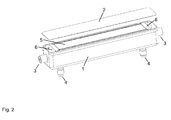
- Figs. 1 and 2 show a capillary dialyzer comprising:
- the housing 1 of the capillary dialyzers of the present invention is a trough-shaped molded part which includes the functionality provided by the end caps in conventional dialyzers. It can be produced in a single step by injection molding of a suitable thermoplastic polymer. Suitable polymers include thermoplastic polymers, e.g., polyethylene, polypropylene, polyesters like PET or PBT, polymethylmethacrylate, polystyrene (HIPS), thermoplastic polyurethane, or polycarbonate. In one embodiment of the present invention, the housing 1 is transparent. In another embodiment, the housing 1 is opaque.
- the housing 1 comprises two blood ports 3 on its front end and rear end, respectively.
- the blood ports 3 are used to feed blood to the dialyzer and remove blood from the dialyzer, respectively.
- Two dialysis fluid ports 4 are provided on the wall of the housing at locations between the first and second end of the bundle 5 of hollow fiber membranes.
- both dialysis fluid ports 4 are located on the bottom side of the housing, near the end wall means 6.
- at least one of the dialysis ports 4 is located on a side wall of the housing 1.
- both dialysis fluid ports 4 are located on the same side wall of the housing 1.
- one port is located on one of the side walls and the other port is located on the opposite side wall of the housing 1.
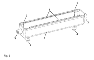
- the housing 1 additionally comprises flexible ears 8 located at the upper part of the inside of each side wall of the housing 1 near the trough opening and extending longitudinally along the housing 1, as shown in Figs. 3 and 4 .
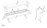
- the flexible ears 8 facilitate introduction of the bundle 5 of hollow fiber membranes into the housing 1 by providing additional guidance and act as an additional retainer for the bundle 5 of hollow fiber membranes when bent into their final position, as shown in Fig. 4 .
- the housing 1 also comprises circumferential ridges 7 in the part of the housing 1 where the end wall means 6 are located.
- the circumferential ridges 7 serve as a support for the bundle 5 of hollow fiber membranes and a spacer between the ends of the hollow fiber membranes and the inner wall of the housing 1 before the potting step.
- the circumferential ridges 7 provide an additional anchor for the end wall means 6.
- the circumferential ridges 7 have an elevation, relative to the inner wall surface of the housing (1), in the range of from 1 to 10 mm, for instance, 2 to 5 mm.
- the cover 2 seals the opening of the trough of the housing 1.
- the cover 2 is transparent.
- the cover 2 is a sheet of a transparent polymer. Suitable transparent polymers include polyethylene, polypropylene, polyurethane, and polycarbonate. The thickness of the sheet generally is in the range of from 0.1 to 0.5 mm, for instance, 0.15 to 0.3 mm.
- the cover 2 is bonded to the seam of the trough-shaped molded part, thus sealing the opening of the trough.
- the cover 2 is bonded to the housing 1 and the end wall means 6 by a suitable process, e.g., welding, heat-sealing, or by means of an adhesive.
- the cover 2 can be equipped with further functions.
- a strain gauge is provided on the cover 2, allowing for detection of strain due to the internal pressure in the dialyzer and thus, measurement of the pressure within the dialyzer.
- the calibration curve of the strain gauge is recorded during the integrity test of the dialyzer and printed on the cover as a Data Matrix code.
- the Data Matrix code can be read by the monitor and used to calculate the pressure within the dialyzer from the observed distortion of the strain gauge.
- the end wall means 6 supporting the first and second ends of the hollow fiber membranes within the internal chamber are generated by potting the ends of the fiber with a reactive polymer.
- a suitable potting material for the hollow fiber membranes is polyurethane.
- the present disclosure also relates to processes for producing the dialyzer of the invention.
- An exemplary process comprises the steps of
- the fiber ends can be closed by processes known in the art, e.g., by melting or by means of an adhesive. In one embodiment of the process the ends of the hollow fiber membranes are closed before the bundle 5 of hollow fiber membranes is introduced into the housing 1.
- a casting mold 9 is introduced into the housing 1. As shown in Fig. 4 for an exemplary embodiment, the casting mold 9 in its final position completely covers the trough opening of the housing 1 and seals off compartments at the first end and at the second end, respectively, of the interior chamber, so that potting material introduced through one or both of the dialysis ports 4 cannot penetrate into these compartments.
- the casting mold 9 also provides spacers between a part of the end wall means 6 on the side facing the blood port 3 and the side walls of the housing 1, as shown in Fig. 4 . As a result, gaps are provided between a portion of the end wall means 6 and the side walls of the housing 1, as shown in Fig. 5 .
- the casting mold 9 also bends the flexible ears 8 into their final position during its introduction into the housing 1, simultaneously pushing peripheral hollow fiber membranes into the housing 1 and further compacting the bundle 5 of hollow fiber membranes, as illustrated by Fig. 4 .
- the ends of the hollow fiber membranes are potted to produce end wall means 6.
- Potting material for instance polyurethane
- the potting material is introduced into the housing via one or both of the dialysis fluid ports 4.
- the potting material is distributed within the housing 1 of the dialyzer by centrifugation, i.e., rotating the dialyzer at high speed perpendicular to its longitudinal axis.
- the potting material is allowed to cure; thereby forming end wall means 6 on both ends of the bundle 5 of hollow fiber membranes.
- the casting mold 9 is removed.
- the ends of the hollow fiber membranes are subsequently opened, for instance by cutting the part of the end wall means 6 facing the blood ports 3 with a blade 10.
- the end wall means 6 are cut diagonally, as shown in Fig. 5 .
- the angle and the starting position of the blade 10 are selected to have the blade 10 cut through the face of the end wall means 6 at a position above the bottom wall of the housing 1, e.g., at a distance in the range of from 0.5 to 2 mm.
- the cutting angle, relative to a plane perpendicular to the bottom wall of the housing 1, is in the range of from 2 to 10°. As the resulting wedge-shaped section does not adhere to the bottom wall of the housing 1, it can easily be removed from the housing 1.
- the cover 2 is mounted on the housing 1 of the dialyzer to close the trough opening of the housing 1.
- the cover 2 is bonded to the housing 1 and the end wall means 6 by a suitable process, e.g., welding, heat-sealing, or by means of an adhesive, for instance, a polyurethane adhesive.
Landscapes
- Health & Medical Sciences (AREA)
- Heart & Thoracic Surgery (AREA)
- Urology & Nephrology (AREA)
- Hematology (AREA)
- Animal Behavior & Ethology (AREA)
- Engineering & Computer Science (AREA)
- Anesthesiology (AREA)
- Biomedical Technology (AREA)
- Emergency Medicine (AREA)
- Life Sciences & Earth Sciences (AREA)
- Vascular Medicine (AREA)
- General Health & Medical Sciences (AREA)
- Public Health (AREA)
- Veterinary Medicine (AREA)
- Chemical & Material Sciences (AREA)
- Chemical Kinetics & Catalysis (AREA)
- External Artificial Organs (AREA)
Abstract
Description
- The present invention relates to capillary dialyzers for blood purification.
- Capillary dialyzers are widely used for blood purification in patients suffering from renal insufficiency, i.e., for treatment of the patients by hemodialysis, hemodiafiltration or hemofiltration. A multitude of different models of capillary dialyzers is commercially available.
- The devices generally consist of a casing comprising a tubular section with end caps capping the mouths of the tubular section. A bundle of hollow fiber membranes is arranged in the casing in a way that a seal is provided between the first flow space formed by the fiber cavities and a second flow space surrounding the membranes on the outside. Examples of such devices are disclosed in
EP 0 844 015 A2 ,EP 0 305 687 A1 , andWO 01/60477 A2 - Hence, commercially available dialyzers at least comprise one housing and two end caps. Generally, they comprise additional parts like sealing rings, gaskets, and support rings. Production, handling, and subsequent assembly of the individual elements add to the complexity of the production process and the manufacturing cost. It would therefore be desirable to reduce the number of individual parts in the dialyzer.
- A capillary dialyzer is provided which does not comprise end caps, sealing rings, or support rings. The dialyzer shell is comprised of a single trough-shaped molded
part 1 havingblood ports 3 anddialysate ports 4; and acover 2 bonded to the seam of the trough-shaped molded part and sealing the opening of the trough. -
- Fig. 1
- shows a perspective view of a capillary dialyzer of the present application;
- Fig. 2
- shows a partially exploded perspective view of a capillary dialyzer of the present application;
- Fig. 3
- shows a perspective view of an embodiment of the housing of the capillary dialyzer of the present application;
- Fig. 4
- shows a perspective view and a cross-sectional view of a bundle of hollow fibers in an embodiment of the housing of the capillary dialyzers of the present invention and a casting mold used during potting of the ends of the bundle of hollow fibers;
- Fig. 5
- shows a detail of a cross-sectional top view and a detail of a longitudinal-sectional perspective view of a bundle of hollow fibers in an embodiment of the housing of the capillary dialyzers of the present invention after potting of the ends of the hollow fibers and before cutting open the ends of the hollow fibers.
-
Figs. 1 and2 show a capillary dialyzer comprising: - a) a trough-
shaped housing 1 defining a longitudinally extending internal chamber including a first end and a second end; - b) a
cover 2 sealing the opening of the trough of thehousing 1; - c) a
bundle 5 of semi-permeable hollow fiber membranes disposed within the internal chamber and extending longitudinally from the first end of the housing to the second end of the housing, the hollow fiber membranes having an outer surface, and a first end and a second end corresponding to the first end and the second end of the internal chamber; - d) end wall means 6 supporting the first and second ends of the hollow fiber membranes within the internal chamber so as to sealingly separate the first and second ends of the hollow fiber membranes from the outer surface of the hollow fiber membranes between the first and second ends thereof;
- e)
blood ports 3 on the front end and rear end, respectively, of thehousing 1; anddialysis fluid ports 4 on the wall of the housing at locations between the first and second end of thebundle 5 of hollow fiber membranes. - The
housing 1 of the capillary dialyzers of the present invention is a trough-shaped molded part which includes the functionality provided by the end caps in conventional dialyzers. It can be produced in a single step by injection molding of a suitable thermoplastic polymer. Suitable polymers include thermoplastic polymers, e.g., polyethylene, polypropylene, polyesters like PET or PBT, polymethylmethacrylate, polystyrene (HIPS), thermoplastic polyurethane, or polycarbonate. In one embodiment of the present invention, thehousing 1 is transparent. In another embodiment, thehousing 1 is opaque. - The
housing 1 comprises twoblood ports 3 on its front end and rear end, respectively. During operation of the dialyzer, theblood ports 3 are used to feed blood to the dialyzer and remove blood from the dialyzer, respectively. Twodialysis fluid ports 4 are provided on the wall of the housing at locations between the first and second end of thebundle 5 of hollow fiber membranes. In one embodiment of the invention shown inFig. 1 , bothdialysis fluid ports 4 are located on the bottom side of the housing, near the end wall means 6. In another embodiment of the invention, at least one of thedialysis ports 4 is located on a side wall of thehousing 1. In still another embodiment of the invention, bothdialysis fluid ports 4 are located on the same side wall of thehousing 1. In still another embodiment of the invention, one port is located on one of the side walls and the other port is located on the opposite side wall of thehousing 1. - In one embodiment of the invention, the
housing 1 additionally comprisesflexible ears 8 located at the upper part of the inside of each side wall of thehousing 1 near the trough opening and extending longitudinally along thehousing 1, as shown inFigs. 3 and4 . Theflexible ears 8 facilitate introduction of thebundle 5 of hollow fiber membranes into thehousing 1 by providing additional guidance and act as an additional retainer for thebundle 5 of hollow fiber membranes when bent into their final position, as shown inFig. 4 . - In another embodiment of the invention, as shown in
Figs. 3 and5 , thehousing 1 also comprisescircumferential ridges 7 in the part of thehousing 1 where the end wall means 6 are located. Thecircumferential ridges 7 serve as a support for thebundle 5 of hollow fiber membranes and a spacer between the ends of the hollow fiber membranes and the inner wall of thehousing 1 before the potting step. After completion of the potting step, thecircumferential ridges 7 provide an additional anchor for the end wall means 6. In one embodiment, thecircumferential ridges 7 have an elevation, relative to the inner wall surface of the housing (1), in the range of from 1 to 10 mm, for instance, 2 to 5 mm. - The
cover 2 seals the opening of the trough of thehousing 1. In one embodiment of the invention, thecover 2 is transparent. In one embodiment of the invention, thecover 2 is a sheet of a transparent polymer. Suitable transparent polymers include polyethylene, polypropylene, polyurethane, and polycarbonate. The thickness of the sheet generally is in the range of from 0.1 to 0.5 mm, for instance, 0.15 to 0.3 mm. Thecover 2 is bonded to the seam of the trough-shaped molded part, thus sealing the opening of the trough. Thecover 2 is bonded to thehousing 1 and the end wall means 6 by a suitable process, e.g., welding, heat-sealing, or by means of an adhesive. Thecover 2 can be equipped with further functions. In one embodiment of the dialyzer, a strain gauge is provided on thecover 2, allowing for detection of strain due to the internal pressure in the dialyzer and thus, measurement of the pressure within the dialyzer. In one embodiment, the calibration curve of the strain gauge is recorded during the integrity test of the dialyzer and printed on the cover as a Data Matrix code. When the dialyzer is connected to a dialysis monitor, the Data Matrix code can be read by the monitor and used to calculate the pressure within the dialyzer from the observed distortion of the strain gauge. - The end wall means 6 supporting the first and second ends of the hollow fiber membranes within the internal chamber are generated by potting the ends of the fiber with a reactive polymer. A suitable potting material for the hollow fiber membranes is polyurethane.
- The present disclosure also relates to processes for producing the dialyzer of the invention. An exemplary process comprises the steps of
- i) providing a trough-shaped
housing 1 defining a longitudinally extending internal chamber including a first end and a second end; and havingblood ports 3 on its front end and rear end wall, respectively; anddialysis fluid ports 4 on its bottom wall and/or side walls; - ii) introducing a
bundle 5 of hollow fiber membranes into the internal chamber of thehousing 1, so that the fibers extend longitudinally from the first end of thehousing 1 to the second end of thehousing 1; - iii) introducing a casting
mold 9 into thehousing 1 which completely covers the trough opening of thehousing 1 and seals off compartments at the first end and at the second end, respectively, of the interior chamber; - iv) potting the ends of the hollow fiber membranes to produce end wall means 6 supporting the ends of the hollow fiber membranes within the internal chamber;
- v) removing the casting
mold 9 from thehousing 1; - vi) cutting the part of the end wall means 6 facing the
blood ports 3 to open the ends of the hollow fiber membranes; and - vii) bonding the
cover 2 to the trough opening of thehousing 1. - It is expedient to close the ends of the hollow fiber membranes before the potting step in order to prevent the potting material from permeating into the fibers. The fiber ends can be closed by processes known in the art, e.g., by melting or by means of an adhesive. In one embodiment of the process the ends of the hollow fiber membranes are closed before the
bundle 5 of hollow fiber membranes is introduced into thehousing 1. - After the
bundle 5 of hollow fiber membranes has been introduced into thehousing 1, a castingmold 9 is introduced into thehousing 1. As shown inFig. 4 for an exemplary embodiment, the castingmold 9 in its final position completely covers the trough opening of thehousing 1 and seals off compartments at the first end and at the second end, respectively, of the interior chamber, so that potting material introduced through one or both of thedialysis ports 4 cannot penetrate into these compartments. - In one embodiment of the process, the casting
mold 9 also provides spacers between a part of the end wall means 6 on the side facing theblood port 3 and the side walls of thehousing 1, as shown inFig. 4 . As a result, gaps are provided between a portion of the end wall means 6 and the side walls of thehousing 1, as shown inFig. 5 . - In an embodiment of the invention where the
housing 1 additionally comprisesflexible ears 8, the castingmold 9 also bends theflexible ears 8 into their final position during its introduction into thehousing 1, simultaneously pushing peripheral hollow fiber membranes into thehousing 1 and further compacting thebundle 5 of hollow fiber membranes, as illustrated byFig. 4 . - With the casting
mold 9 in its final position, the ends of the hollow fiber membranes are potted to produce end wall means 6. Potting material, for instance polyurethane, is introduced into the housing via one or both of thedialysis fluid ports 4. The potting material is distributed within thehousing 1 of the dialyzer by centrifugation, i.e., rotating the dialyzer at high speed perpendicular to its longitudinal axis. The potting material is allowed to cure; thereby forming end wall means 6 on both ends of thebundle 5 of hollow fiber membranes. After the potting material has hardened, the castingmold 9 is removed. - The ends of the hollow fiber membranes are subsequently opened, for instance by cutting the part of the end wall means 6 facing the
blood ports 3 with ablade 10. The end wall means 6 are cut diagonally, as shown inFig. 5 . In one embodiment of the process, the angle and the starting position of theblade 10 are selected to have theblade 10 cut through the face of the end wall means 6 at a position above the bottom wall of thehousing 1, e.g., at a distance in the range of from 0.5 to 2 mm. The cutting angle, relative to a plane perpendicular to the bottom wall of thehousing 1, is in the range of from 2 to 10°. As the resulting wedge-shaped section does not adhere to the bottom wall of thehousing 1, it can easily be removed from thehousing 1. This is even more so for embodiments where a gap is provided between the section to be cut off from the end wall means 6 and the side walls of thehousing 1, as shown inFig. 5 . In one embodiment of the process, the cuts at both end wall means 6 of the dialyzer are mirror-symmetrical to each other. - After the ends of the hollow fiber membranes have been opened, the
cover 2 is mounted on thehousing 1 of the dialyzer to close the trough opening of thehousing 1. Thecover 2 is bonded to thehousing 1 and the end wall means 6 by a suitable process, e.g., welding, heat-sealing, or by means of an adhesive, for instance, a polyurethane adhesive.
Claims (12)
- A dialyzer shell comprised of a trough-shaped molded part (1) having blood ports (3) and dialysate ports (4); and a cover (2) sealing the opening of the trough of the trough-shaped molded part (1).
- The dialyzer shell of claim 1, wherein the cover (2) is a sheet of a transparent polymer.
- The dialyzer shell of claims 1 or 2, wherein the transparent polymer is polypropylene.
- The dialyzer shell of any one of claims 1 to 3, wherein a strain gauge is provided on the cover (2).
- The dialyzer shell of any one of claims 1 to 4, wherein the trough-shaped molded part (1) is comprised of polypropylene.
- The dialyzer shell of any one of claims 1 to 4, wherein the trough-shaped molded part (1) is comprised of polycarbonate.
- A capillary dialyzer comprising:a) a trough-shaped housing (1) defining a longitudinally extending internal chamber including a first end and a second end;b) a cover (2) sealing the opening of the trough of the housing (1) ;c) a bundle (5) of semi-permeable hollow fiber membranes disposed within the internal chamber and extending longitudinally from the first end of the housing to the second end of the housing, the hollow fiber membranes having an outer surface, and a first end and a second end corresponding to the first end and the second end of the internal chamber;d) end wall means (6) supporting the first and second ends of the hollow fiber membranes within the internal chamber so as to sealingly separate the first and second ends of the hollow fiber membranes from the outer surface of the hollow fiber membranes between the first and second ends thereof;e) blood ports (3) on the front end and rear end, respectively, of the housing (1); and dialysis fluid ports (4) on the wall of the housing at locations between the first and second end of the bundle (5) of hollow fiber membranes.
- The capillary dialyzer of claim 7, wherein the housing (1) further comprises circumferential ridges (7) within the end wall means (6).
- The capillary dialyzer of claim 8, wherein the circumferential ridges (7) have an elevation relative to the inner wall surface of the housing (1) which is in the range of from 1 to 10 mm.
- A process for producing a capillary dialyzer comprising the steps ofi) providing a trough-shaped housing (1) defining a longitudinally extending internal chamber including a first end and a second end; and having blood ports (3) on its front end wall and rear end wall, respectively; and dialysis fluid ports (4) on its bottom wall and/or side walls;ii) introducing a bundle (5) of hollow fiber membranes into the internal chamber of the housing (1), so that the fibers extend longitudinally from the first end of the housing (1) to the second end of the housing (1) ;iii) introducing a casting mold (9) into the housing (1) which completely covers the trough opening of the housing (1) and seals off compartments at the first end and at the second end, respectively, of the interior chamber;iv) potting the ends of the hollow fiber membranes to produce end wall means (6) supporting the ends of the hollow fiber membranes within the internal chamber;v) removing the casting mold (9) from the housing (1) ;vi) cutting the part of the end wall means (6) facing the blood ports (3) to open the ends of the hollow fiber membranes; andvii) bonding a cover (2) to the trough opening of the housing (1).
- The process of claim 10, wherein the casting mold (9) is shaped to provide spacers between a part of the end wall means (6) on the side facing the blood port (3) and the side walls of the housing (1).
- The process of claims 10 or 11, wherein the end wall means (6) are cut with a blade (10) at an angle, relative to a plane perpendicular to the bottom wall of the housing (1), in the range of from 2 to 10°.
Priority Applications (3)
| Application Number | Priority Date | Filing Date | Title |
|---|---|---|---|
| EP12193791.6A EP2735358B1 (en) | 2012-11-22 | 2012-11-22 | Capillary dialyzers |
| CN201380028236.XA CN104349833B (en) | 2012-11-22 | 2013-11-22 | Capillary dialyzers |
| PCT/EP2013/074523 WO2014079991A1 (en) | 2012-11-22 | 2013-11-22 | Capillary dialyzers |
Applications Claiming Priority (1)
| Application Number | Priority Date | Filing Date | Title |
|---|---|---|---|
| EP12193791.6A EP2735358B1 (en) | 2012-11-22 | 2012-11-22 | Capillary dialyzers |
Publications (2)
| Publication Number | Publication Date |
|---|---|
| EP2735358A1 true EP2735358A1 (en) | 2014-05-28 |
| EP2735358B1 EP2735358B1 (en) | 2018-01-10 |
Family
ID=47227652
Family Applications (1)
| Application Number | Title | Priority Date | Filing Date |
|---|---|---|---|
| EP12193791.6A Active EP2735358B1 (en) | 2012-11-22 | 2012-11-22 | Capillary dialyzers |
Country Status (3)
| Country | Link |
|---|---|
| EP (1) | EP2735358B1 (en) |
| CN (1) | CN104349833B (en) |
| WO (1) | WO2014079991A1 (en) |
Cited By (7)
| Publication number | Priority date | Publication date | Assignee | Title |
|---|---|---|---|---|
| US11712501B2 (en) | 2019-11-12 | 2023-08-01 | Fresenius Medical Care Deutschland Gmbh | Blood treatment systems |
| US11730871B2 (en) | 2019-11-12 | 2023-08-22 | Fresenius Medical Care Deutschland Gmbh | Blood treatment systems |
| US11752247B2 (en) | 2019-11-12 | 2023-09-12 | Fresenius Medical Care Deutschland Gmbh | Blood treatment systems |
| US11925736B2 (en) | 2019-11-12 | 2024-03-12 | Fresenius Medical Care Deutschland Gmbh | Blood treatment systems |
| US12285553B2 (en) | 2019-11-12 | 2025-04-29 | Fresenius Medical Care Deutschland Gmbh | Blood treatment systems |
| US12329890B2 (en) | 2019-11-12 | 2025-06-17 | Fresenius Medical Care Deutschland Gmbh | Blood treatment systems |
| US12558468B2 (en) | 2019-12-12 | 2026-02-24 | Fresenius Medical Care Holdings, Inc. | Blood treatment systems |
Families Citing this family (2)
| Publication number | Priority date | Publication date | Assignee | Title |
|---|---|---|---|---|
| JP6926331B2 (en) | 2017-10-05 | 2021-08-25 | フレセニウス メディカル ケア ホールディングス インコーポレーテッド | Polysulfone-urethane copolymers, membranes and products containing them, and their manufacture and use |
| US20240021848A1 (en) * | 2020-12-30 | 2024-01-18 | Kolon Industries, Inc. | Cartridge of fuel cell humidifier, and fuel cell humidifier |
Citations (9)
| Publication number | Priority date | Publication date | Assignee | Title |
|---|---|---|---|---|
| US4038190A (en) * | 1973-05-30 | 1977-07-26 | Rhone-Poulenc S.A. | Fluid fractionation apparatus and method of manufacturing the same |
| US4343668A (en) * | 1980-06-04 | 1982-08-10 | Hospal Sodip Sa | Method of producing bundles of hollow fibres potted at their ends |
| EP0305687A1 (en) | 1987-08-31 | 1989-03-08 | Gambro Dialysatoren GmbH & Co. KG | A diffusion and/or filtration apparatus and a method of manufacturing said apparatus |
| EP0844015A2 (en) | 1996-11-21 | 1998-05-27 | Fresenius Medical Care Deutschland GmbH | Hollow fiber membrane separation device |
| WO2001060477A2 (en) | 2000-02-17 | 2001-08-23 | Fresenius Medical Care Deutschland Gmbh | Filter device, preferably a hollow fibre dialyser, comprising curled hollow fibres |
| US20030010718A1 (en) * | 2001-07-12 | 2003-01-16 | Nxstage Medical, Inc. | Hemodilution cap and methods of use in blood-processing procedures |
| US20030102264A1 (en) * | 2001-12-05 | 2003-06-05 | Pope Rodney William | Filtering device with associated sealing design and method |
| EP1398047A1 (en) * | 2002-09-11 | 2004-03-17 | Gambro Lundia AB | End-cap for a dialyser, dialyser and method for removing gas bubbles |
| EP1864709A2 (en) * | 2006-06-05 | 2007-12-12 | Celgard LLC | A membrane contactor |
Family Cites Families (3)
| Publication number | Priority date | Publication date | Assignee | Title |
|---|---|---|---|---|
| JP4508555B2 (en) * | 2003-06-11 | 2010-07-21 | 旭化成クラレメディカル株式会社 | Hollow fiber membrane type body fluid treatment device |
| CN101972497B (en) * | 2010-12-01 | 2013-08-07 | 贝恩医疗设备(广州)有限公司 | Process for preparing dialyzer |
| CN102078646A (en) * | 2011-01-22 | 2011-06-01 | 江西三鑫医疗器械集团有限公司 | Polyether sulfone hollow fiber blood dialyzer |
-
2012
- 2012-11-22 EP EP12193791.6A patent/EP2735358B1/en active Active
-
2013
- 2013-11-22 CN CN201380028236.XA patent/CN104349833B/en active Active
- 2013-11-22 WO PCT/EP2013/074523 patent/WO2014079991A1/en not_active Ceased
Patent Citations (9)
| Publication number | Priority date | Publication date | Assignee | Title |
|---|---|---|---|---|
| US4038190A (en) * | 1973-05-30 | 1977-07-26 | Rhone-Poulenc S.A. | Fluid fractionation apparatus and method of manufacturing the same |
| US4343668A (en) * | 1980-06-04 | 1982-08-10 | Hospal Sodip Sa | Method of producing bundles of hollow fibres potted at their ends |
| EP0305687A1 (en) | 1987-08-31 | 1989-03-08 | Gambro Dialysatoren GmbH & Co. KG | A diffusion and/or filtration apparatus and a method of manufacturing said apparatus |
| EP0844015A2 (en) | 1996-11-21 | 1998-05-27 | Fresenius Medical Care Deutschland GmbH | Hollow fiber membrane separation device |
| WO2001060477A2 (en) | 2000-02-17 | 2001-08-23 | Fresenius Medical Care Deutschland Gmbh | Filter device, preferably a hollow fibre dialyser, comprising curled hollow fibres |
| US20030010718A1 (en) * | 2001-07-12 | 2003-01-16 | Nxstage Medical, Inc. | Hemodilution cap and methods of use in blood-processing procedures |
| US20030102264A1 (en) * | 2001-12-05 | 2003-06-05 | Pope Rodney William | Filtering device with associated sealing design and method |
| EP1398047A1 (en) * | 2002-09-11 | 2004-03-17 | Gambro Lundia AB | End-cap for a dialyser, dialyser and method for removing gas bubbles |
| EP1864709A2 (en) * | 2006-06-05 | 2007-12-12 | Celgard LLC | A membrane contactor |
Cited By (7)
| Publication number | Priority date | Publication date | Assignee | Title |
|---|---|---|---|---|
| US11712501B2 (en) | 2019-11-12 | 2023-08-01 | Fresenius Medical Care Deutschland Gmbh | Blood treatment systems |
| US11730871B2 (en) | 2019-11-12 | 2023-08-22 | Fresenius Medical Care Deutschland Gmbh | Blood treatment systems |
| US11752247B2 (en) | 2019-11-12 | 2023-09-12 | Fresenius Medical Care Deutschland Gmbh | Blood treatment systems |
| US11925736B2 (en) | 2019-11-12 | 2024-03-12 | Fresenius Medical Care Deutschland Gmbh | Blood treatment systems |
| US12285553B2 (en) | 2019-11-12 | 2025-04-29 | Fresenius Medical Care Deutschland Gmbh | Blood treatment systems |
| US12329890B2 (en) | 2019-11-12 | 2025-06-17 | Fresenius Medical Care Deutschland Gmbh | Blood treatment systems |
| US12558468B2 (en) | 2019-12-12 | 2026-02-24 | Fresenius Medical Care Holdings, Inc. | Blood treatment systems |
Also Published As
| Publication number | Publication date |
|---|---|
| EP2735358B1 (en) | 2018-01-10 |
| WO2014079991A1 (en) | 2014-05-30 |
| CN104349833A (en) | 2015-02-11 |
| CN104349833B (en) | 2017-05-03 |
Similar Documents
| Publication | Publication Date | Title |
|---|---|---|
| EP2735358B1 (en) | Capillary dialyzers | |
| US4211597A (en) | Method for making artificial kidney | |
| EP0165478B1 (en) | A method of producing a device including a bundle of hollow fibers | |
| US4231871A (en) | Artificial kidney and method for making same | |
| KR20100005011A (en) | Method of forming body fluid purification cassette | |
| US11426698B2 (en) | Diffusion and/or filtration device | |
| JP4852873B2 (en) | Method for producing hollow fiber membrane module | |
| JPS60500246A (en) | Manufacture of separation equipment | |
| US20070278145A1 (en) | Membrane contactor | |
| JP4118293B2 (en) | Body fluid purification cassette molding method | |
| EP2878362B1 (en) | Capillary dialyzers | |
| US5002668A (en) | Housing containing a penetrable membrane sealing an evacuation outlet | |
| US12161974B2 (en) | Process for making a filtration and/or diffusion device | |
| CN109562325A (en) | The method for manufacturing membrane filter | |
| JP2011224026A (en) | Blood purification device and method of manufacturing the same | |
| WO1985000989A1 (en) | Improved dialyzer side ports and manufacturing method | |
| US20090236027A1 (en) | Blood Treatment Filter and Method of Manufacturing | |
| GB2052301A (en) | Improved medical separatory device and method of making same | |
| JP2019042650A (en) | Membrane module | |
| US11298448B2 (en) | Filter unit for whole blood and blood derivatives | |
| JP2007330846A (en) | Method for producing hollow fiber membrane module | |
| CN120897792A (en) | Method of encapsulating hollow fiber membrane bundles in a filter housing | |
| JP2016041409A (en) | Hollow fiber membrane module | |
| JPH11128694A (en) | Hollow fiber membrane module and method of manufacturing the same |
Legal Events
| Date | Code | Title | Description |
|---|---|---|---|
| PUAI | Public reference made under article 153(3) epc to a published international application that has entered the european phase |
Free format text: ORIGINAL CODE: 0009012 |
|
| 17P | Request for examination filed |
Effective date: 20121122 |
|
| AK | Designated contracting states |
Kind code of ref document: A1 Designated state(s): AL AT BE BG CH CY CZ DE DK EE ES FI FR GB GR HR HU IE IS IT LI LT LU LV MC MK MT NL NO PL PT RO RS SE SI SK SM TR |
|
| AX | Request for extension of the european patent |
Extension state: BA ME |
|
| R17P | Request for examination filed (corrected) |
Effective date: 20141127 |
|
| RBV | Designated contracting states (corrected) |
Designated state(s): AL AT BE BG CH CY CZ DE DK EE ES FI FR GB GR HR HU IE IS IT LI LT LU LV MC MK MT NL NO PL PT RO RS SE SI SK SM TR |
|
| GRAP | Despatch of communication of intention to grant a patent |
Free format text: ORIGINAL CODE: EPIDOSNIGR1 |
|
| INTG | Intention to grant announced |
Effective date: 20171011 |
|
| GRAS | Grant fee paid |
Free format text: ORIGINAL CODE: EPIDOSNIGR3 |
|
| GRAA | (expected) grant |
Free format text: ORIGINAL CODE: 0009210 |
|
| AK | Designated contracting states |
Kind code of ref document: B1 Designated state(s): AL AT BE BG CH CY CZ DE DK EE ES FI FR GB GR HR HU IE IS IT LI LT LU LV MC MK MT NL NO PL PT RO RS SE SI SK SM TR |
|
| REG | Reference to a national code |
Ref country code: CH Ref legal event code: EP Ref country code: AT Ref legal event code: REF Ref document number: 961789 Country of ref document: AT Kind code of ref document: T Effective date: 20180115 |
|
| REG | Reference to a national code |
Ref country code: IE Ref legal event code: FG4D |
|
| REG | Reference to a national code |
Ref country code: DE Ref legal event code: R096 Ref document number: 602012041941 Country of ref document: DE |
|
| REG | Reference to a national code |
Ref country code: NL Ref legal event code: MP Effective date: 20180110 |
|
| REG | Reference to a national code |
Ref country code: AT Ref legal event code: MK05 Ref document number: 961789 Country of ref document: AT Kind code of ref document: T Effective date: 20180110 |
|
| PG25 | Lapsed in a contracting state [announced via postgrant information from national office to epo] |
Ref country code: NL Free format text: LAPSE BECAUSE OF FAILURE TO SUBMIT A TRANSLATION OF THE DESCRIPTION OR TO PAY THE FEE WITHIN THE PRESCRIBED TIME-LIMIT Effective date: 20180110 |
|
| PG25 | Lapsed in a contracting state [announced via postgrant information from national office to epo] |
Ref country code: ES Free format text: LAPSE BECAUSE OF FAILURE TO SUBMIT A TRANSLATION OF THE DESCRIPTION OR TO PAY THE FEE WITHIN THE PRESCRIBED TIME-LIMIT Effective date: 20180110 Ref country code: LT Free format text: LAPSE BECAUSE OF FAILURE TO SUBMIT A TRANSLATION OF THE DESCRIPTION OR TO PAY THE FEE WITHIN THE PRESCRIBED TIME-LIMIT Effective date: 20180110 Ref country code: CY Free format text: LAPSE BECAUSE OF FAILURE TO SUBMIT A TRANSLATION OF THE DESCRIPTION OR TO PAY THE FEE WITHIN THE PRESCRIBED TIME-LIMIT Effective date: 20180110 Ref country code: HR Free format text: LAPSE BECAUSE OF FAILURE TO SUBMIT A TRANSLATION OF THE DESCRIPTION OR TO PAY THE FEE WITHIN THE PRESCRIBED TIME-LIMIT Effective date: 20180110 Ref country code: NO Free format text: LAPSE BECAUSE OF FAILURE TO SUBMIT A TRANSLATION OF THE DESCRIPTION OR TO PAY THE FEE WITHIN THE PRESCRIBED TIME-LIMIT Effective date: 20180410 Ref country code: FI Free format text: LAPSE BECAUSE OF FAILURE TO SUBMIT A TRANSLATION OF THE DESCRIPTION OR TO PAY THE FEE WITHIN THE PRESCRIBED TIME-LIMIT Effective date: 20180110 |
|
| PG25 | Lapsed in a contracting state [announced via postgrant information from national office to epo] |
Ref country code: IS Free format text: LAPSE BECAUSE OF FAILURE TO SUBMIT A TRANSLATION OF THE DESCRIPTION OR TO PAY THE FEE WITHIN THE PRESCRIBED TIME-LIMIT Effective date: 20180510 Ref country code: RS Free format text: LAPSE BECAUSE OF FAILURE TO SUBMIT A TRANSLATION OF THE DESCRIPTION OR TO PAY THE FEE WITHIN THE PRESCRIBED TIME-LIMIT Effective date: 20180110 Ref country code: SE Free format text: LAPSE BECAUSE OF FAILURE TO SUBMIT A TRANSLATION OF THE DESCRIPTION OR TO PAY THE FEE WITHIN THE PRESCRIBED TIME-LIMIT Effective date: 20180110 Ref country code: LV Free format text: LAPSE BECAUSE OF FAILURE TO SUBMIT A TRANSLATION OF THE DESCRIPTION OR TO PAY THE FEE WITHIN THE PRESCRIBED TIME-LIMIT Effective date: 20180110 Ref country code: PL Free format text: LAPSE BECAUSE OF FAILURE TO SUBMIT A TRANSLATION OF THE DESCRIPTION OR TO PAY THE FEE WITHIN THE PRESCRIBED TIME-LIMIT Effective date: 20180110 Ref country code: AT Free format text: LAPSE BECAUSE OF FAILURE TO SUBMIT A TRANSLATION OF THE DESCRIPTION OR TO PAY THE FEE WITHIN THE PRESCRIBED TIME-LIMIT Effective date: 20180110 Ref country code: GR Free format text: LAPSE BECAUSE OF FAILURE TO SUBMIT A TRANSLATION OF THE DESCRIPTION OR TO PAY THE FEE WITHIN THE PRESCRIBED TIME-LIMIT Effective date: 20180411 Ref country code: BG Free format text: LAPSE BECAUSE OF FAILURE TO SUBMIT A TRANSLATION OF THE DESCRIPTION OR TO PAY THE FEE WITHIN THE PRESCRIBED TIME-LIMIT Effective date: 20180410 |
|
| REG | Reference to a national code |
Ref country code: DE Ref legal event code: R097 Ref document number: 602012041941 Country of ref document: DE |
|
| REG | Reference to a national code |
Ref country code: FR Ref legal event code: PLFP Year of fee payment: 7 |
|
| PG25 | Lapsed in a contracting state [announced via postgrant information from national office to epo] |
Ref country code: RO Free format text: LAPSE BECAUSE OF FAILURE TO SUBMIT A TRANSLATION OF THE DESCRIPTION OR TO PAY THE FEE WITHIN THE PRESCRIBED TIME-LIMIT Effective date: 20180110 Ref country code: AL Free format text: LAPSE BECAUSE OF FAILURE TO SUBMIT A TRANSLATION OF THE DESCRIPTION OR TO PAY THE FEE WITHIN THE PRESCRIBED TIME-LIMIT Effective date: 20180110 Ref country code: IT Free format text: LAPSE BECAUSE OF FAILURE TO SUBMIT A TRANSLATION OF THE DESCRIPTION OR TO PAY THE FEE WITHIN THE PRESCRIBED TIME-LIMIT Effective date: 20180110 Ref country code: EE Free format text: LAPSE BECAUSE OF FAILURE TO SUBMIT A TRANSLATION OF THE DESCRIPTION OR TO PAY THE FEE WITHIN THE PRESCRIBED TIME-LIMIT Effective date: 20180110 |
|
| PLBE | No opposition filed within time limit |
Free format text: ORIGINAL CODE: 0009261 |
|
| STAA | Information on the status of an ep patent application or granted ep patent |
Free format text: STATUS: NO OPPOSITION FILED WITHIN TIME LIMIT |
|
| PG25 | Lapsed in a contracting state [announced via postgrant information from national office to epo] |
Ref country code: DK Free format text: LAPSE BECAUSE OF FAILURE TO SUBMIT A TRANSLATION OF THE DESCRIPTION OR TO PAY THE FEE WITHIN THE PRESCRIBED TIME-LIMIT Effective date: 20180110 Ref country code: SM Free format text: LAPSE BECAUSE OF FAILURE TO SUBMIT A TRANSLATION OF THE DESCRIPTION OR TO PAY THE FEE WITHIN THE PRESCRIBED TIME-LIMIT Effective date: 20180110 Ref country code: SK Free format text: LAPSE BECAUSE OF FAILURE TO SUBMIT A TRANSLATION OF THE DESCRIPTION OR TO PAY THE FEE WITHIN THE PRESCRIBED TIME-LIMIT Effective date: 20180110 Ref country code: CZ Free format text: LAPSE BECAUSE OF FAILURE TO SUBMIT A TRANSLATION OF THE DESCRIPTION OR TO PAY THE FEE WITHIN THE PRESCRIBED TIME-LIMIT Effective date: 20180110 |
|
| 26N | No opposition filed |
Effective date: 20181011 |
|
| PG25 | Lapsed in a contracting state [announced via postgrant information from national office to epo] |
Ref country code: SI Free format text: LAPSE BECAUSE OF FAILURE TO SUBMIT A TRANSLATION OF THE DESCRIPTION OR TO PAY THE FEE WITHIN THE PRESCRIBED TIME-LIMIT Effective date: 20180110 |
|
| REG | Reference to a national code |
Ref country code: CH Ref legal event code: PL |
|
| PG25 | Lapsed in a contracting state [announced via postgrant information from national office to epo] |
Ref country code: MC Free format text: LAPSE BECAUSE OF FAILURE TO SUBMIT A TRANSLATION OF THE DESCRIPTION OR TO PAY THE FEE WITHIN THE PRESCRIBED TIME-LIMIT Effective date: 20180110 Ref country code: LU Free format text: LAPSE BECAUSE OF NON-PAYMENT OF DUE FEES Effective date: 20181122 |
|
| REG | Reference to a national code |
Ref country code: BE Ref legal event code: MM Effective date: 20181130 |
|
| REG | Reference to a national code |
Ref country code: IE Ref legal event code: MM4A |
|
| PG25 | Lapsed in a contracting state [announced via postgrant information from national office to epo] |
Ref country code: CH Free format text: LAPSE BECAUSE OF NON-PAYMENT OF DUE FEES Effective date: 20181130 Ref country code: LI Free format text: LAPSE BECAUSE OF NON-PAYMENT OF DUE FEES Effective date: 20181130 |
|
| PG25 | Lapsed in a contracting state [announced via postgrant information from national office to epo] |
Ref country code: IE Free format text: LAPSE BECAUSE OF NON-PAYMENT OF DUE FEES Effective date: 20181122 |
|
| PG25 | Lapsed in a contracting state [announced via postgrant information from national office to epo] |
Ref country code: BE Free format text: LAPSE BECAUSE OF NON-PAYMENT OF DUE FEES Effective date: 20181130 |
|
| PG25 | Lapsed in a contracting state [announced via postgrant information from national office to epo] |
Ref country code: MT Free format text: LAPSE BECAUSE OF NON-PAYMENT OF DUE FEES Effective date: 20181122 |
|
| PG25 | Lapsed in a contracting state [announced via postgrant information from national office to epo] |
Ref country code: TR Free format text: LAPSE BECAUSE OF FAILURE TO SUBMIT A TRANSLATION OF THE DESCRIPTION OR TO PAY THE FEE WITHIN THE PRESCRIBED TIME-LIMIT Effective date: 20180110 |
|
| PG25 | Lapsed in a contracting state [announced via postgrant information from national office to epo] |
Ref country code: PT Free format text: LAPSE BECAUSE OF FAILURE TO SUBMIT A TRANSLATION OF THE DESCRIPTION OR TO PAY THE FEE WITHIN THE PRESCRIBED TIME-LIMIT Effective date: 20180110 |
|
| PG25 | Lapsed in a contracting state [announced via postgrant information from national office to epo] |
Ref country code: MK Free format text: LAPSE BECAUSE OF NON-PAYMENT OF DUE FEES Effective date: 20180110 Ref country code: HU Free format text: LAPSE BECAUSE OF FAILURE TO SUBMIT A TRANSLATION OF THE DESCRIPTION OR TO PAY THE FEE WITHIN THE PRESCRIBED TIME-LIMIT; INVALID AB INITIO Effective date: 20121122 |
|
| PGFP | Annual fee paid to national office [announced via postgrant information from national office to epo] |
Ref country code: DE Payment date: 20251022 Year of fee payment: 14 |
|
| PGFP | Annual fee paid to national office [announced via postgrant information from national office to epo] |
Ref country code: GB Payment date: 20251023 Year of fee payment: 14 |
|
| PGFP | Annual fee paid to national office [announced via postgrant information from national office to epo] |
Ref country code: FR Payment date: 20251023 Year of fee payment: 14 |