EP2735046B1 - Use of ammonia as source of hydrogen fuel and as a getter for air-co2 in alkaline membrane fuel cells - Google Patents
Use of ammonia as source of hydrogen fuel and as a getter for air-co2 in alkaline membrane fuel cells Download PDFInfo
- Publication number
- EP2735046B1 EP2735046B1 EP12802234.0A EP12802234A EP2735046B1 EP 2735046 B1 EP2735046 B1 EP 2735046B1 EP 12802234 A EP12802234 A EP 12802234A EP 2735046 B1 EP2735046 B1 EP 2735046B1
- Authority
- EP
- European Patent Office
- Prior art keywords
- ammonia
- fuel cell
- amfc
- cell system
- air
- Prior art date
- Legal status (The legal status is an assumption and is not a legal conclusion. Google has not performed a legal analysis and makes no representation as to the accuracy of the status listed.)
- Active
Links
Images

Classifications
-
- H—ELECTRICITY
- H01—ELECTRIC ELEMENTS
- H01M—PROCESSES OR MEANS, e.g. BATTERIES, FOR THE DIRECT CONVERSION OF CHEMICAL ENERGY INTO ELECTRICAL ENERGY
- H01M8/00—Fuel cells; Manufacture thereof
- H01M8/06—Combination of fuel cells with means for production of reactants or for treatment of residues
- H01M8/0606—Combination of fuel cells with means for production of reactants or for treatment of residues with means for production of gaseous reactants
-
- H—ELECTRICITY
- H01—ELECTRIC ELEMENTS
- H01M—PROCESSES OR MEANS, e.g. BATTERIES, FOR THE DIRECT CONVERSION OF CHEMICAL ENERGY INTO ELECTRICAL ENERGY
- H01M8/00—Fuel cells; Manufacture thereof
- H01M8/02—Details
- H01M8/0202—Collectors; Separators, e.g. bipolar separators; Interconnectors
- H01M8/0258—Collectors; Separators, e.g. bipolar separators; Interconnectors characterised by the configuration of channels, e.g. by the flow field of the reactant or coolant
- H01M8/0263—Collectors; Separators, e.g. bipolar separators; Interconnectors characterised by the configuration of channels, e.g. by the flow field of the reactant or coolant having meandering or serpentine paths
-
- H—ELECTRICITY
- H01—ELECTRIC ELEMENTS
- H01M—PROCESSES OR MEANS, e.g. BATTERIES, FOR THE DIRECT CONVERSION OF CHEMICAL ENERGY INTO ELECTRICAL ENERGY
- H01M8/00—Fuel cells; Manufacture thereof
- H01M8/06—Combination of fuel cells with means for production of reactants or for treatment of residues
- H01M8/0662—Treatment of gaseous reactants or gaseous residues, e.g. cleaning
- H01M8/0668—Removal of carbon monoxide or carbon dioxide
-
- H—ELECTRICITY
- H01—ELECTRIC ELEMENTS
- H01M—PROCESSES OR MEANS, e.g. BATTERIES, FOR THE DIRECT CONVERSION OF CHEMICAL ENERGY INTO ELECTRICAL ENERGY
- H01M8/00—Fuel cells; Manufacture thereof
- H01M8/22—Fuel cells in which the fuel is based on materials comprising carbon or oxygen or hydrogen and other elements; Fuel cells in which the fuel is based on materials comprising only elements other than carbon, oxygen or hydrogen
- H01M8/222—Fuel cells in which the fuel is based on compounds containing nitrogen, e.g. hydrazine, ammonia
-
- H—ELECTRICITY
- H01—ELECTRIC ELEMENTS
- H01M—PROCESSES OR MEANS, e.g. BATTERIES, FOR THE DIRECT CONVERSION OF CHEMICAL ENERGY INTO ELECTRICAL ENERGY
- H01M8/00—Fuel cells; Manufacture thereof
- H01M8/10—Fuel cells with solid electrolytes
- H01M2008/1095—Fuel cells with polymeric electrolytes
-
- H—ELECTRICITY
- H01—ELECTRIC ELEMENTS
- H01M—PROCESSES OR MEANS, e.g. BATTERIES, FOR THE DIRECT CONVERSION OF CHEMICAL ENERGY INTO ELECTRICAL ENERGY
- H01M8/00—Fuel cells; Manufacture thereof
- H01M8/06—Combination of fuel cells with means for production of reactants or for treatment of residues
-
- Y—GENERAL TAGGING OF NEW TECHNOLOGICAL DEVELOPMENTS; GENERAL TAGGING OF CROSS-SECTIONAL TECHNOLOGIES SPANNING OVER SEVERAL SECTIONS OF THE IPC; TECHNICAL SUBJECTS COVERED BY FORMER USPC CROSS-REFERENCE ART COLLECTIONS [XRACs] AND DIGESTS
- Y02—TECHNOLOGIES OR APPLICATIONS FOR MITIGATION OR ADAPTATION AGAINST CLIMATE CHANGE
- Y02E—REDUCTION OF GREENHOUSE GAS [GHG] EMISSIONS, RELATED TO ENERGY GENERATION, TRANSMISSION OR DISTRIBUTION
- Y02E60/00—Enabling technologies; Technologies with a potential or indirect contribution to GHG emissions mitigation
- Y02E60/30—Hydrogen technology
- Y02E60/36—Hydrogen production from non-carbon containing sources, e.g. by water electrolysis
-
- Y—GENERAL TAGGING OF NEW TECHNOLOGICAL DEVELOPMENTS; GENERAL TAGGING OF CROSS-SECTIONAL TECHNOLOGIES SPANNING OVER SEVERAL SECTIONS OF THE IPC; TECHNICAL SUBJECTS COVERED BY FORMER USPC CROSS-REFERENCE ART COLLECTIONS [XRACs] AND DIGESTS
- Y02—TECHNOLOGIES OR APPLICATIONS FOR MITIGATION OR ADAPTATION AGAINST CLIMATE CHANGE
- Y02E—REDUCTION OF GREENHOUSE GAS [GHG] EMISSIONS, RELATED TO ENERGY GENERATION, TRANSMISSION OR DISTRIBUTION
- Y02E60/00—Enabling technologies; Technologies with a potential or indirect contribution to GHG emissions mitigation
- Y02E60/30—Hydrogen technology
- Y02E60/50—Fuel cells
Definitions
- This invention relates to the field of Alkaline Membrane Fuel Cells (AMFCs) and particular to utilizing ammonia as a source to generate electricity.
- AMFCs Alkaline Membrane Fuel Cells
- AMFCs Alkaline membrane fuel cells
- JP2010282755 (A ) discloses a fuel cell system using ammonia for fuel including an ammonia decomposition device decomposing ammonia into hydrogen and nitrogen, and a fuel cell extracting power with hydrogen generated at the decomposition device as fuel.
- the ammonia decomposition device includes: an ammonia oxidation band in a circulating-type reactor; and an ammonia decomposition band at a downstream side of the band.
- the fuel cell is an anion exchange membrane-type fuel cell.
- DE1771321 discloses an alkaline electrolyte fuel cell system, in which carbon dioxide is removed from the inlet flow of air to the cathode of the fuel cell by reaction with an ammonia aqueous solution formed from the products of the decomposition reaction of hydrazine to produce hydrogen for the fuel cell.
- the invention according to claim 1 provides an ammonia operated fuel cell system including an alkaline membrane fuel cell (AMFC) having an anode, a cathode, a cathode inlet and an air feed stream upstream of the cathode inlet, and an ammonia thermal cracker including a combustion chamber, the cracker being in gas communication with an ammonia tank, and configured to provide a supply of H 2 directly to the AMFC anode wherein the air feed stream is configured to receive a bleed of ammonia from the ammonia tank.
- AMFC alkaline membrane fuel cell
- Implementations of the invention can include one or more of the following features. Exhaust from the anode of the AMFC is fed into the combustion chamber of the cracker.
- the cracker is configured to produce an output of substantially 75% Hydrogen and 25% Nitrogen.
- the ammonia operated fuel cell further includes a flow channel configured to provide a substantially uniform concentration of H 2 to substantially all parts of an active area of the AMFC.
- the flow channel includes a spiral in a first rotational sense between an inlet and a center and a spiral in a second rotational sense between the center and the outlet.
- a cathode of the AMFC is in gas communication with the ammonia source.
- An air supply to a cathode of the AMFC is configured to getter CO 2 from the air supply.
- An exhaust from a cathode of the AMFC is fed into the combustion chamber of the ammonia cracker.
- Hydrogen can be provided to an AMFC using bottled ammonia.
- An ammonia cracker can be configured to provide Hydrogen to an AMFC using the bottled ammonia.
- gettering of the CO 2 by ammonia can be accomplished.
- AMFCs can be operated in area where there is a short supply of neat Hydrogen. Up to a 5x extension of operation time per tank fill-up can be accomplished due to the higher density of liquefied ammonia versus that of compressed hydrogen, in a 200 bar cylinder.
- Embodiments of the invention provide techniques for providing H 2 to an AMFC using ammonia cracker.
- the ammonia is provided to the AMFC system from bottles of liquid ammonia contained under low pressure.
- Ammonia flows from the bottle to the thermal cracker, which is configured to produce H 2 that is provided to the AMFC.
- the Hydrogen/Nitrogen mixture generated by the cracker can be distributed along the active area of the AMFC using a flow channel that is optimized (e.g., using a series of counter-oriented spirals) to provide a substantially uniform distribution of H 2 to the electrode active area.
- the AMFC system can also be configured such that exhaust from an anode and/or cathode of the AMFC is directed to a combustion chamber of the ammonia cracker.
- the AMFC system can be further configured such that ammonia is bled into an air feed stream of the AMFC to preferably reduce carbonation of the OH - conducting ionomer by CO 2 gettering.
- Other embodiments are within the scope of
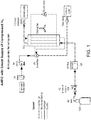
- FIG. 1 shows an example of an AMFC stack 100 with a compressed hydrogen tank 102 as the fuel source. This is a simple AMFC system design due at least in part to the direct feed into the stack 100 of the stored fuel 102 through a hydrogen pressure reducer 104 and a hydrogen flow controller.
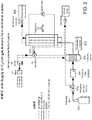
- FIG. 2 illustrates an AMFC fed by an ammonia storage tank 200.
- the ammonia storage tank can feed ammonia gas through an ammonia pressure reducer 202 and an ammonia flow controller to a thermal cracker 206 which generates a 75% Hydrogen/25% Nitrogen gas mixture to be used as the fuel feed stream for the stack 210.
- FIG. 2 shows release of the anode exhaust 208 to the outside atmosphere as an option, the anode exhaust 208 in such system can also be fed into the fuel inlet of the combustor component 212 of the cracker.
- the combustor component 212 then uses the anode exhaust gas as fuel for the combustor.
- ammonia instead of Hydrogen to fuel the AMFC system can be beneficial because, for example, ammonia is typically much more accessible over large areas of the world when compared with compressed Hydrogen, particularly so in rural areas, and because a tank of a given volume filled by ammonia contains 5x the energy versus that same tank filled by compressed hydrogen at 200 bars.
- the conversion of protons to ammonium ions according to Equation (2) can deactivate a PEMFC. Since the conversion occurs at even sub-ppm levels of ammonia in the fuel feed, cracking ammonia according to Equation (1) to generate a fuel feed for a PEMFC can be done only at the expense of the inclusion in the feed stream of a highly effective ammonia filtering system which will guarantee 100% removal of the smallest traces of ammonia resulting from imperfect conversion of ammonia in the cracker to Hydrogen by the process identified in Equation (1).
- the ionic functionality in the alkaline membrane used in the AMFC is itself a base, OH-, and consequently no reaction of NH 3 residues from the cracker occurs with the ionomer in the AMFC.
- the teaching provided here of a combination of an ammonia cracker with an AMFC therefore addresses a significantly taller challenge of immunity of both the membrane material and the catalysts, to high local concentrations of ammonia, particularly when the ammonia levels allowed in the cracker exhaust are high, as preferred for smaller cracker size , lower cracker cost and lower energy demand.
- FIG. 3 shows an exemplary unique type flow field which preferably provides a uniform Hydrogen concentration across the active area of an AMFC cell, in spite of the large drop in hydrogen concentration between inlet and outlet ports under high fuel utilization conditions.
- the unique flow field 300 shown in FIG. 3 includes a spiral in a first direction 302 (e.g., a counter clockwise-spiral direction) between an inlet and the center followed by a second spiral in a second direction 304 (e.g., clockwise spiral direction) between the center and an outlet, with the inlet and outlet ports preferably positioned at close proximity.
- the result of such flow field design is that each element of the active area is preferably fed by a pair of channels of Hydrogen concentrations which, on average, are the same.
- each portion of the active area will preferably have next to it a Hydrogen-rich and a Hydrogen-poor channel that offset each other to feed the active area with a mixture that is preferably 50% Hydrogen and 50% inactive gas.
- the two adjacent channels will preferably contain 75% and 25% Hydrogen, respectively.
- the active area near the inlet is preferably fed by a 50% Hydrogen and 50% inactive gas mixture.
- the breakdown could be 60% and 40% Hydrogen, which again averages to 50% Hydrogen to that area. The exact values can depend on the actual degree of fuel utilization.
- the configuration shown in FIG. 3 ensures a Hydrogen concentration having a good uniformity (e.g., 50%) across the active area. This is in contrast to a system that has a sharp drop from 75% to 25% Hydrogen concentration between the inlet and outlet when an ordinary flow field is used (i.e., a flow field without a "turning around at the center. ").
- ammonia as "C0 2 getter” in a system of the type described in FIG. 2 .
- the technique described in that patent application is based on C0 2 sequestration sub-units placed upstream the cell and an in-situ, electrochemical decarbonation taking place at the cell anode.
- Equation (5) The process of Equation (5) is known to degrade the AMFC performance significantly.
- ammonia when ammonia is available next right to the stack, it could be used for CO 2 sequestration according to Equations (3) and (4), thereby relieving the cell of air CO 2 related performance losses while avoiding the need of an additional unit and active material for that purpose.
- a remaining important question is how to achieve high efficiency of this process, as reflected by the probability of the reactions of Equations (3) and (4) much exceeding the probability of ionomer carbonation by CO2 entering through the air cathode, according to (5).
- Ammonia can be naturally fed into the cell with the Hydrogen/Nitrogen fuel mix (e.g., it is fed into the cell anode and its level in the feed stream can be elevated to, for example, 0.1% in the anode feed), to achieve CO 2 sequestration.
- this mode of ammonia supply to the cell is not likely to fulfill the requirement of the probability of processes (3) or (4) occurring being much higher than the probability of process (5) occurring.
- the reason is that any CO 2 molecule that enters first into the cell cathode of an operating AMFC, encounters there a current-sustained population of -(NR 4 + )(OH -- ) groups, as the cathode process is generating continuously OH - ions. Consequently, CO 2 entering the cathode will typically convert at high probability to carbonate according to process (5), before being significantly exposed to any ammonia entering the cell from its other (fuel) side.
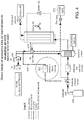
- FIG. 4 An exemplary innovative approach to the resolution of this difficulty is shown in FIG. 4 .
- some ammonia may be bled 402 from the ammonia tank 404 into the air feed stream 406 upstream the cathode inlet, so as to react with air-C0 2 according to Equations (3) and (4) before the air and any of the C0 2 in it reaches the cathode.
- the C0 2 can be fed upstream of a water exchanger used to humidify the incoming air stream and the C0 2 gettering process of Equation (3) and (4) can then take place while the air stream is passing through the water exchanger.
- a tube 410 filled with inert high surface area substrate can be placed between the water exchanger and the cathode inlet to preferably increase the probability of the encounter between an ammonia/water mix and the air-C0 2 .
- Other similar means for sustaining high efficiency of the gettering process of Equations (3) and (4) by providing proper inert substrate surface area and securing supply of sufficient water for processes Equations (3) and (4) are possible.
- bleeding of ammonia into the air feed stream either upstream a water exchanger or a tube section upstream the cathode inlet containing an inert, high surface area substrate will preferably ensure a high probability of gettering air- C0 2 by ammonia and, thereby prevent carbonation of the AMFC ionomer.
- the cathode exhaust stream 412 could contain ammonia at a level of the order of, for example, 0.1% and, consequently, release of such stream to the ambient air is likely to be unacceptable in many locations.
- Routing the stack air exhaust into the combustor preferably resolves this issue, as ammonia is fully combusted at the temperature of the combustor in the presence of the large excess of independent air feed (e.g,. FIG. 4 ).
Landscapes
- Life Sciences & Earth Sciences (AREA)
- Engineering & Computer Science (AREA)
- Manufacturing & Machinery (AREA)
- Sustainable Development (AREA)
- Sustainable Energy (AREA)
- Chemical & Material Sciences (AREA)
- Chemical Kinetics & Catalysis (AREA)
- Electrochemistry (AREA)
- General Chemical & Material Sciences (AREA)
- Fuel Cell (AREA)
- Incineration Of Waste (AREA)
Description
- This invention relates to the field of Alkaline Membrane Fuel Cells (AMFCs) and particular to utilizing ammonia as a source to generate electricity.
- Alkaline membrane fuel cells (AMFCs) generate electricity using mostly Hydrogen fuel. In the past, the Hydrogen source considered for AMFC fuel cell stacks has been a tank of compressed Hydrogen gas connected to the AMFC. Compressed Hydrogen, however, is not easily available in many parts of the world, and handling of compressed H2 gas tanks can be demanding because of transport regulations and because of the low weight % Hydrogen in such gas tanks. Ammonia tanks, on the other hand, contain liquid ammonia under pressure of several bars and consequently have significantly higher weight % of Hydrogen versus compressed H2 gas. Use of ammonia as source of Hydrogen can therefore provide an improvement in Hydrogen fuel packaging and facilitates fuel supply in many rural areas where ammonia is much more readily available than compressed Hydrogen.
-
JP2010282755 (A -
DE1771321 discloses an alkaline electrolyte fuel cell system, in which carbon dioxide is removed from the inlet flow of air to the cathode of the fuel cell by reaction with an ammonia aqueous solution formed from the products of the decomposition reaction of hydrazine to produce hydrogen for the fuel cell. - The invention according to claim 1 provides an ammonia operated fuel cell system including an alkaline membrane fuel cell (AMFC) having an anode, a cathode, a cathode inlet and an air feed stream upstream of the cathode inlet, and an ammonia thermal cracker including a combustion chamber, the cracker being in gas communication with an ammonia tank, and configured to provide a supply of H2 directly to the AMFC anode wherein the air feed stream is configured to receive a bleed of ammonia from the ammonia tank.
- Implementations of the invention can include one or more of the following features. Exhaust from the anode of the AMFC is fed into the combustion chamber of the cracker. The cracker is configured to produce an output of substantially 75% Hydrogen and 25% Nitrogen. The ammonia operated fuel cell further includes a flow channel configured to provide a substantially uniform concentration of H2 to substantially all parts of an active area of the AMFC. The flow channel includes a spiral in a first rotational sense between an inlet and a center and a spiral in a second rotational sense between the center and the outlet. A cathode of the AMFC is in gas communication with the ammonia source. An air supply to a cathode of the AMFC is configured to getter CO2 from the air supply. An exhaust from a cathode of the AMFC is fed into the combustion chamber of the ammonia cracker.
- Various aspects of the invention may provide one or more of the following capabilities. Hydrogen can be provided to an AMFC using bottled ammonia. An ammonia cracker can be configured to provide Hydrogen to an AMFC using the bottled ammonia. To prevent carbonation of the AMFC ionomer by CO2 entering the AMFC with the air stream, gettering of the CO2 by ammonia can be accomplished. AMFCs can be operated in area where there is a short supply of neat Hydrogen. Up to a 5x extension of operation time per tank fill-up can be accomplished due to the higher density of liquefied ammonia versus that of compressed hydrogen, in a 200 bar cylinder.
- These and other capabilities of the invention, along with the invention itself, will be more fully understood after a review of the following figures, detailed description, and claims.
-
-
FIG. 1 shows a schematic diagram of an AMFC system with a direct supply of H2. -
FIG. 2 shows a schematic diagram of an AMFC system with a supply of H2-rich gas mixture from an ammonia cracker. -
FIG. 3 shows a schematic diagram of a flow channel. -
FIG. 4 shows a schematic diagram of an AMFC system with a direct bleed of ammonia into an air feed stream. - Embodiments of the invention provide techniques for providing H2 to an AMFC using ammonia cracker. Preferably, the ammonia is provided to the AMFC system from bottles of liquid ammonia contained under low pressure. Ammonia flows from the bottle to the thermal cracker, which is configured to produce H2 that is provided to the AMFC. The Hydrogen/Nitrogen mixture generated by the cracker can be distributed along the active area of the AMFC using a flow channel that is optimized (e.g., using a series of counter-oriented spirals) to provide a substantially uniform distribution of H2 to the electrode active area. The AMFC system can also be configured such that exhaust from an anode and/or cathode of the AMFC is directed to a combustion chamber of the ammonia cracker. The AMFC system can be further configured such that ammonia is bled into an air feed stream of the AMFC to preferably reduce carbonation of the OH- conducting ionomer by CO2 gettering. Other embodiments are within the scope of the invention.
-
FIG. 1 shows an example of an AMFCstack 100 with acompressed hydrogen tank 102 as the fuel source. This is a simple AMFC system design due at least in part to the direct feed into thestack 100 of the storedfuel 102 through ahydrogen pressure reducer 104 and a hydrogen flow controller. -
FIG. 2 illustrates an AMFC fed by anammonia storage tank 200. The ammonia storage tank can feed ammonia gas through anammonia pressure reducer 202 and an ammonia flow controller to athermal cracker 206 which generates a 75% Hydrogen/25% Nitrogen gas mixture to be used as the fuel feed stream for thestack 210. WhileFIG. 2 shows release of theanode exhaust 208 to the outside atmosphere as an option, theanode exhaust 208 in such system can also be fed into the fuel inlet of thecombustor component 212 of the cracker. Thecombustor component 212 then uses the anode exhaust gas as fuel for the combustor. With the major feed to thecombustor 212 being the tank-stored ammonia fuel, thecombustor 212 can maintain the temperature required for the catalytic decomposition of ammonia into its component elements, according to:
2NH3 + heat = N2+3H2 (1)
- The use of ammonia instead of Hydrogen to fuel the AMFC system can be beneficial because, for example, ammonia is typically much more accessible over large areas of the world when compared with compressed Hydrogen, particularly so in rural areas, and because a tank of a given volume filled by ammonia contains 5x the energy versus that same tank filled by compressed hydrogen at 200 bars. One important characteristic of ammonia, which explains the reluctance to use it as hydrogen carrier for mainstream fuel cells utilizing proton conducting membranes (PEMFCs), is the ultra-high sensitivity of a PEMFC to even minute traces of ammonia, that can react aggressively by a base/acid type process to convert protons in the acidic ionomer to ammonium ions, according to:
NH3 + H+ = NH4 + (2)
- The conversion of protons to ammonium ions according to Equation (2) can deactivate a PEMFC. Since the conversion occurs at even sub-ppm levels of ammonia in the fuel feed, cracking ammonia according to Equation (1) to generate a fuel feed for a PEMFC can be done only at the expense of the inclusion in the feed stream of a highly effective ammonia filtering system which will guarantee 100% removal of the smallest traces of ammonia resulting from imperfect conversion of ammonia in the cracker to Hydrogen by the process identified in Equation (1). In contrast, the ionic functionality in the alkaline membrane used in the AMFC is itself a base, OH-, and consequently no reaction of NH3 residues from the cracker occurs with the ionomer in the AMFC.
- This is not to say, however, that other elements of the AMFC cell and hardware are guaranteed immunity in the presence of ammonia residues in the fuel feed stream. However, surprisingly, initial testing performed on a system constructed in accordance with
FIG. 2 , showed that, up to significant cell current levels, the performance of the AMFC operating on cracked ammonia was substantially identical to the performance of the same AMFC operating using neat hydrogen gas. Such initial testing suggests that, at the ammonia levels of 1 ppm to 20,000 ppm (the level that was present in the fuel feed stream during our test), there is no significant performance loss incurred by the ammonia entering the AMFC anode. This demonstrates that, in turn, no catalyst deactivation or other material instability was caused by the entry into the AMFC anode of ammonia at a level 100x higher than that required to completely deactivate a PEMFC. - It is believed that this is a first report of a reduction to practice of the system shown in
FIG. 2 , consisting of an AMFC stack fed by thermally cracked ammonia, while confirming the viability of operation with no filtration of ammonia residues upstream of the stack fuel inlet by demonstrating performance comparable to that obtained with a neat Hydrogen feed in operation on non-filtered, thermally cracked ammonia with ammonia levels of the order of 1 ppm to 20,000 ppm in the non-filtered anode feed stream. - Kordesch et al described in
US patent No 6,936,363 , use of an ammonia thermal cracker as source of hydrogen for an Alkaline Fuel Cell (AFC) which uses an aqueous solution of KOH as electrolyte. An important relevant difference between the AMFC (membrane electrolyte fuel cell) and an AFC (liquid electrolyte fuel cell)), is that the total volume of water per unit area of the electrode is several orders of magnitude smaller in the case of the AMFC. Consequently, the concentration of ammonia in contact with the electrode surface in the AMFC is much higher at some given level of ammonia residue in the hydrogen feed stream. The teaching provided here of a combination of an ammonia cracker with an AMFC , therefore addresses a significantly taller challenge of immunity of both the membrane material and the catalysts, to high local concentrations of ammonia, particularly when the ammonia levels allowed in the cracker exhaust are high, as preferred for smaller cracker size , lower cracker cost and lower energy demand. - Potential problems arise when switching from 100% hydrogen feed of a system like that of
FIG. 1 to 75% hydrogen mixed with 25% inert gas (e.g., Nitrogen) like that ofFIG. 2 one issue is how to operate at high fuel utilization without loss of performance having to do with the drop of Hydrogen concentration near the fuel outlet well below the inlet level of 75%. This is fully expected as Hydrogen is consumed along the flow channel while the inert component of the anode gas mixture remains intact. Such continuous dilution of the reactant Hydrogen gas is typically a smaller problem in a PEMFC, because the anode process in the PEMFC does not face the extra challenge of excess water buildup incurred in the AMFC anode. In the AMFC, the anode is the water generating electrode. Consequently, some given degree of hydrogen dilution by inert gas will have a stronger mass transport consequences in the water rich AMFC anode. - An innovative approach to meet this important challenge of operating an AMFC with diluted Hydrogen gas at high performance under high fuel utilization conditions has been discovered, relying on a simple, one-pass mode for the fuel feed.
-
FIG. 3 shows an exemplary unique type flow field which preferably provides a uniform Hydrogen concentration across the active area of an AMFC cell, in spite of the large drop in hydrogen concentration between inlet and outlet ports under high fuel utilization conditions. Theunique flow field 300 shown inFIG. 3 includes a spiral in a first direction 302 (e.g., a counter clockwise-spiral direction) between an inlet and the center followed by a second spiral in a second direction 304 (e.g., clockwise spiral direction) between the center and an outlet, with the inlet and outlet ports preferably positioned at close proximity. The result of such flow field design is that each element of the active area is preferably fed by a pair of channels of Hydrogen concentrations which, on average, are the same. For example, each portion of the active area will preferably have next to it a Hydrogen-rich and a Hydrogen-poor channel that offset each other to feed the active area with a mixture that is preferably 50% Hydrogen and 50% inactive gas. As a further example, near the inlet, the two adjacent channels will preferably contain 75% and 25% Hydrogen, respectively. Thus, the active area near the inlet is preferably fed by a 50% Hydrogen and 50% inactive gas mixture. At another area, the breakdown could be 60% and 40% Hydrogen, which again averages to 50% Hydrogen to that area. The exact values can depend on the actual degree of fuel utilization. Preferably, the configuration shown inFIG. 3 ensures a Hydrogen concentration having a good uniformity (e.g., 50%) across the active area. This is in contrast to a system that has a sharp drop from 75% to 25% Hydrogen concentration between the inlet and outlet when an ordinary flow field is used (i.e., a flow field without a "turning around at the center. "). - Next is described an innovative approach to the use of ammonia as "C02 getter" in a system of the type described in
FIG. 2 . Once ammonia is stored next to an AMFC fuel cell stack as the source of the hydrogen fuel, was determined that the ammonia can provide an additional function of special importance for the AMFC C02 immunity. - A previous Patent Application
US20110212370A1 entitled "Systems and Methods of Security Immunity to Air C02 in Alkaline Fuel Cells", and assigned to the assignee of the present application, describes a comprehensive technique to prevent AMFC losses incurred by entry of air-C02 into the AMFC cathode. The technique described in that patent application is based on C02 sequestration sub-units placed upstream the cell and an in-situ, electrochemical
decarbonation taking place at the cell anode. While ammine or hydroxide active materials were used for sequestration of C02 in our previous Patent Application, here ammonia preferably undergoes base-acid reaction with C02 to form ammonium carbonate:
NH3 + H20 + C02 = (NH4 +)(HC03 -) (3)
and/or
2NH3 + H2O + CO2 = (NH4 +)2(CO3 =) (4)
Capturing CO2 by ammonia in this way, can prevent carbonation of the functional groups in the polymer by air CO2, according to:
-(NR4 +)(OH-) + CO2 = -(NR4 +)(HCO3-) (5)
where -(NR4 +)(OH-) is preferably a tetra-alkyl ammonium hydroxide functional group of the AMFC ionomer and -(NR4 +)(HCO3 -) is the carbonated (i.e., deactivated) form of such functional group. The process of Equation (5) is known to degrade the AMFC performance significantly. Thus, when ammonia is available next right to the stack, it could be used for CO2 sequestration according to Equations (3) and (4), thereby relieving the cell of air CO2 related performance losses while avoiding the need of an additional unit and active material for that purpose. Once the CO2 neutralization function of the ammonia available next to a stack, according to Equations (3) and (4), is considered, a remaining important question is how to achieve high efficiency of this process, as reflected by the probability of the reactions of Equations (3) and (4) much exceeding the probability of ionomer carbonation by CO2 entering through the air cathode, according to (5). - Ammonia can be naturally fed into the cell with the Hydrogen/Nitrogen fuel mix (e.g., it is fed into the cell anode and its level in the feed stream can be elevated to, for example, 0.1% in the anode feed), to achieve CO2 sequestration. However, this mode of ammonia supply to the cell is not likely to fulfill the requirement of the probability of processes (3) or (4) occurring being much higher than the probability of process (5) occurring. The reason is that any CO2 molecule that enters first into the cell cathode of an operating AMFC, encounters there a current-sustained population of
-(NR4 +)(OH--) groups, as the cathode process is generating continuously OH- ions. Consequently, CO2 entering the cathode will typically convert at high probability to carbonate according to process (5), before being significantly exposed to any ammonia entering the cell from its other (fuel) side. - An exemplary innovative approach to the resolution of this difficulty is shown in
FIG. 4 . According to this scheme, some ammonia may be bled 402 from theammonia tank 404 into theair feed stream 406 upstream the cathode inlet, so as to react with air-C02 according to Equations (3) and (4) before the air and any of the C02 in it reaches the cathode. The C02 can be fed upstream of a water exchanger used to humidify the incoming air stream and the C02 gettering process of Equation (3) and (4) can then take place while the air stream is passing through the water exchanger. To further increase the probability of C02 gettering by the ammonia bled into theair feed stream 408, atube 410 filled with inert high surface area substrate can be placed between the water exchanger and the cathode inlet to preferably increase the probability of the encounter between an ammonia/water mix and the air-C02. Other similar means for sustaining high efficiency of the gettering process of Equations (3) and (4) by providing proper inert substrate surface area and securing supply of sufficient water for processes Equations (3) and (4) are possible. In summary, bleeding of ammonia into the air feed stream either upstream a water exchanger or a tube section upstream the cathode inlet containing an inert, high surface area substrate, will preferably ensure a high probability of gettering air- C02 by ammonia and, thereby prevent carbonation of the AMFC ionomer.
When bleeding ammonia into the air feed stream, as shown inFIG. 4 , thecathode exhaust stream 412 could contain ammonia at a level of the order of, for example, 0.1% and, consequently, release of such stream to the ambient air is likely to be unacceptable in many locations. In a preferred system design, the cathode exhaust in the system described inFIG. 4 , rather than being released to the ambient air is fed into the combustor component of the thermal cracker. Routing the stack air exhaust into the combustor preferably resolves this issue, as ammonia is fully combusted at the temperature of the combustor in the presence of the large excess of independent air feed (e.g,.FIG. 4 ). - Other embodiments are within the scope of the invention. For example, due to the nature of software, functions described above can be implemented using software, hardware, firmware, hardwiring, or combinations of any of these. Features implementing functions may also be physically located at various positions, including being distributed such that portions of functions are implemented at different physical locations.
Claims (12)
- An ammonia operated fuel cell system comprising:an alkaline membrane fuel cell (AMFC) having an anode, a cathode, a cathode inlet and an air feed stream upstream of the cathode inlet;an ammonia thermal cracker including a combustion chamber, the cracker being in gas communication with an ammonia tank, and configured to provide a supply of Hydrogen directly to the AMFC anode;characterised in that,
the air feed stream is configured to receive a bleed of ammonia from the ammonia tank. - The ammonia operated fuel cell system of claim 1 wherein exhaust from the anode of the AMFC is fed into the combustion chamber of the cracker.
- The ammonia operated fuel cell system of claim 1 wherein the cracker is configured to produce an output of substantially 75% Hydrogen and 25% Nitrogen.
- The ammonia operated fuel cell system of claim 1 further comprising a flow channel configured to provide a substantially uniform concentration of Hydrogen to substantially all parts of an active area of the AMFC.
- The ammonia operated fuel cell system of claim 4 wherein the flow channel includes a spiral in a first rotational sense between an inlet and a center and a spiral in a second rotational sense between the center and the outlet.
- The ammonia operated fuel cell system of claim 1 wherein the bleed of ammonia is configured to getter carbon dioxide from the air supply.
- The ammonia operated fuel cell system of claim 1 wherein an exhaust from a cathode of the AMFC is fed into the combustion chamber of the ammonia cracker.
- The ammonia operated fuel cell system of claim 1 wherein the cracker output also contains levels of ammonia residues from about 1ppm to about 20,000ppm.
- The ammonia operated fuel cell system of claim 1 where the thermal cracker is heated substantially by combustion of ammonia.
- The ammonia operated fuel cell system of claim 6 further comprising a water exchanger arranged to humidify incoming air from the air feed stream, and wherein the ammonia bleed is upstream of the water exchanger.
- The ammonia operated fuel cell system of claim 6 further comprising a water exchanger arranged to humidify incoming air from the air feed stream and a tube filled with inert high surface area substrate placed between the water exchanger and the cathode inlet to increase the probability of encounter between an ammonia/water mix and air-carbon dioxide, wherein the ammonia bleed is upstream of the water exchanger.
- The ammonia operated fuel cell system of claim 6 further comprising a water exchanger arranged to humidify incoming air from the air feed stream and a tube filled with inert high surface area substrate placed between the water exchanger and the cathode inlet to increase the probability of encounter between an ammonia/water mix and air-carbon dioxide, wherein the ammonia bleed is upstream of the tube.
Applications Claiming Priority (2)
| Application Number | Priority Date | Filing Date | Title |
|---|---|---|---|
| US201161500879P | 2011-06-24 | 2011-06-24 | |
| PCT/US2012/043519 WO2012177855A1 (en) | 2011-06-24 | 2012-06-21 | Use of ammonia as source of hydrogen fuel and as a getter for air-co2 in alkaline membrane fuel cells |
Publications (3)
| Publication Number | Publication Date |
|---|---|
| EP2735046A1 EP2735046A1 (en) | 2014-05-28 |
| EP2735046A4 EP2735046A4 (en) | 2015-08-19 |
| EP2735046B1 true EP2735046B1 (en) | 2017-01-11 |
Family
ID=47422941
Family Applications (1)
| Application Number | Title | Priority Date | Filing Date |
|---|---|---|---|
| EP12802234.0A Active EP2735046B1 (en) | 2011-06-24 | 2012-06-21 | Use of ammonia as source of hydrogen fuel and as a getter for air-co2 in alkaline membrane fuel cells |
Country Status (4)
| Country | Link |
|---|---|
| US (2) | US20130130136A1 (en) |
| EP (1) | EP2735046B1 (en) |
| JP (1) | JP6073037B2 (en) |
| WO (1) | WO2012177855A1 (en) |
Families Citing this family (9)
| Publication number | Priority date | Publication date | Assignee | Title |
|---|---|---|---|---|
| JP6420682B2 (en) * | 2015-02-06 | 2018-11-07 | 株式会社トクヤマ | Fuel cell system |
| JP2018063748A (en) * | 2015-02-27 | 2018-04-19 | 株式会社トクヤマ | Anion exchange membrane fuel cell operating method and fuel cell system |
| US11724245B2 (en) | 2021-08-13 | 2023-08-15 | Amogy Inc. | Integrated heat exchanger reactors for renewable fuel delivery systems |
| US12000333B2 (en) | 2021-05-14 | 2024-06-04 | AMOGY, Inc. | Systems and methods for processing ammonia |
| EP4352008A4 (en) | 2021-06-11 | 2025-07-02 | Amogy Inc | SYSTEMS AND METHODS FOR PROCESSING AMMONIA |
| US11539063B1 (en) | 2021-08-17 | 2022-12-27 | Amogy Inc. | Systems and methods for processing hydrogen |
| US11834334B1 (en) | 2022-10-06 | 2023-12-05 | Amogy Inc. | Systems and methods of processing ammonia |
| US11866328B1 (en) | 2022-10-21 | 2024-01-09 | Amogy Inc. | Systems and methods for processing ammonia |
| US11795055B1 (en) | 2022-10-21 | 2023-10-24 | Amogy Inc. | Systems and methods for processing ammonia |
Family Cites Families (19)
| Publication number | Priority date | Publication date | Assignee | Title |
|---|---|---|---|---|
| DE1771321C3 (en) * | 1968-05-07 | 1974-03-21 | Varta Ag, 6000 Frankfurt | Process for operating fuel elements with alkaline electrolytes |
| JPH02168569A (en) * | 1988-08-22 | 1990-06-28 | Fuji Electric Co Ltd | Fuel battery power generating system |
| US5133842A (en) * | 1988-11-17 | 1992-07-28 | Physical Sciences, Inc. | Electrochemical cell having electrode comprising gold containing electrocatalyst |
| JPH10284094A (en) * | 1997-04-10 | 1998-10-23 | Asahi Glass Co Ltd | Fuel cell |
| AU2001281329A1 (en) * | 2000-07-25 | 2002-02-05 | Apollo Energy Systems, Incorporated | Ammonia cracker for production of hydrogen |
| US6551736B1 (en) * | 2000-10-30 | 2003-04-22 | Teledyne Energy Systems, Inc. | Fuel cell collector plates with improved mass transfer channels |
| EP1372839A4 (en) * | 2001-03-02 | 2006-11-29 | Mesofuel Inc | Ammonia-based hydrogen generation apparatus and method for using same |
| JP2003040602A (en) * | 2001-07-30 | 2003-02-13 | Toyota Central Res & Dev Lab Inc | Hydrogen production equipment for fuel cells |
| TW540832U (en) * | 2002-05-23 | 2003-07-01 | Asia Pacific Fuel Cell Tech | Fluency of assembled electrode plate of fuel battery set |
| US20050118485A1 (en) * | 2002-11-22 | 2005-06-02 | Hazem Tawfik | Bipolar plate and electrolyte application |
| US20040163313A1 (en) * | 2003-02-20 | 2004-08-26 | Buxbaum Robert E. | Hydrogen generation apparatus |
| JP2005145748A (en) * | 2003-11-14 | 2005-06-09 | Tama Tlo Kk | Hydrogen production apparatus |
| WO2007078292A2 (en) | 2005-12-30 | 2007-07-12 | Utc Power Corporation | Air bleed through fuel cell fuel recycle loop |
| US8557466B2 (en) * | 2006-06-21 | 2013-10-15 | Panasonic Corporation | Fuel cell including separator with gas flow channels |
| CA2763147C (en) * | 2008-06-04 | 2018-07-24 | Cellera, Inc. | Alkaline membrane fuel cells and apparatus and methods for supplying water thereto |
| US8628889B2 (en) * | 2008-10-10 | 2014-01-14 | Tokuyama Corporation | Operating method of anion-exchange membrane-type fuel cell |
| JP5346693B2 (en) * | 2009-06-02 | 2013-11-20 | 日立造船株式会社 | Fuel cell system using ammonia as fuel |
| JP5404233B2 (en) * | 2009-07-30 | 2014-01-29 | 株式会社トクヤマ | Power generation system using alkaline fuel cell and fuel gas for alkaline fuel cell used in the system |
| WO2011025797A1 (en) | 2009-08-24 | 2011-03-03 | Cellera, Inc. | Systems and methods of securing immunity to air co2 in alkaline fuel cells |
-
2012
- 2012-06-21 JP JP2014517152A patent/JP6073037B2/en active Active
- 2012-06-21 EP EP12802234.0A patent/EP2735046B1/en active Active
- 2012-06-21 WO PCT/US2012/043519 patent/WO2012177855A1/en not_active Ceased
- 2012-06-21 US US13/529,188 patent/US20130130136A1/en not_active Abandoned
-
2014
- 2014-03-04 US US14/196,165 patent/US9236624B2/en active Active
Non-Patent Citations (1)
| Title |
|---|
| None * |
Also Published As
| Publication number | Publication date |
|---|---|
| US20130130136A1 (en) | 2013-05-23 |
| JP2014526115A (en) | 2014-10-02 |
| EP2735046A1 (en) | 2014-05-28 |
| WO2012177855A1 (en) | 2012-12-27 |
| US20140186728A1 (en) | 2014-07-03 |
| US9236624B2 (en) | 2016-01-12 |
| JP6073037B2 (en) | 2017-02-01 |
| EP2735046A4 (en) | 2015-08-19 |
Similar Documents
| Publication | Publication Date | Title |
|---|---|---|
| US9236624B2 (en) | Use of ammonia as source of hydrogen fuel and as a getter for air-CO2 in alkaline membrane fuel cells | |
| US10906804B2 (en) | Devices and methods for hydrogen generation via ammonia decomposition | |
| US11769893B2 (en) | Systems and methods for processing hydrogen | |
| US20120043219A1 (en) | Electrochemical process for the production of synthesis gas using atmospheric air and water | |
| CA3005628C (en) | Fuel cell system having enhanced co2 capture | |
| KR100959116B1 (en) | Fuel container and fuel cell system having same | |
| US20090068512A1 (en) | Hydrogen refueling station | |
| KR20190087529A (en) | Fuel cell system | |
| WO2019204857A1 (en) | Offshore energy generation system | |
| KR20070085688A (en) | Pretreatment assembly for pretreatment of fuel feedstock used in fuel cell systems | |
| KR20100046433A (en) | Unified fuel processing reactor for solid oxide fuel cell | |
| KR20120133660A (en) | Hybrid system and ship having the same | |
| US20150353384A1 (en) | Forward osmosis-type fresh water composite system | |
| KR20120077462A (en) | Fuel cell system and ship having the same | |
| KR101447864B1 (en) | Inert gas purging system for fuel cell system of a ship | |
| EP4517889A1 (en) | Carbon dioxide capture and carbon resource utilization system, for fuel cell, using boil-off gas generated from liquefied natural gas | |
| EP3650407B1 (en) | Hydrogen oxygen reaction device | |
| KR101662671B1 (en) | Fuel cell system having impurity reuse structure | |
| KR102829882B1 (en) | Carbon dioxide capture and carbon resource conversion system for fuel cells and method therefor | |
| US9634344B2 (en) | Hydrogen purifier, hydrogen generation apparatus, and fuel cell system | |
| JP2012109064A (en) | Fuel cell power generation system | |
| JP2011076835A (en) | Fuel cell system | |
| JP2005166486A (en) | Direct type fuel cell system | |
| WO2024044244A2 (en) | Renewable energy integration with natural-gas based combined hydrogen and electricity production (chep) system and method | |
| KR20250100495A (en) | Hydrogen production system with unreacted ammonia removal device |
Legal Events
| Date | Code | Title | Description |
|---|---|---|---|
| PUAI | Public reference made under article 153(3) epc to a published international application that has entered the european phase |
Free format text: ORIGINAL CODE: 0009012 |
|
| 17P | Request for examination filed |
Effective date: 20140121 |
|
| AK | Designated contracting states |
Kind code of ref document: A1 Designated state(s): AL AT BE BG CH CY CZ DE DK EE ES FI FR GB GR HR HU IE IS IT LI LT LU LV MC MK MT NL NO PL PT RO RS SE SI SK SM TR |
|
| DAX | Request for extension of the european patent (deleted) | ||
| RIN1 | Information on inventor provided before grant (corrected) |
Inventor name: PAGE, MILES Inventor name: GOTTESFELD, ZIV Inventor name: DEKEL, DARIO Inventor name: GOTTESFELD, SHIMSHON |
|
| RIC1 | Information provided on ipc code assigned before grant |
Ipc: H01M 8/04 20060101ALI20150223BHEP Ipc: H01M 8/10 20060101ALN20150223BHEP Ipc: H01M 8/22 20060101ALI20150223BHEP Ipc: H01M 8/06 20060101AFI20150223BHEP |
|
| RA4 | Supplementary search report drawn up and despatched (corrected) |
Effective date: 20150721 |
|
| RIC1 | Information provided on ipc code assigned before grant |
Ipc: H01M 8/02 20060101ALI20150715BHEP Ipc: H01M 8/10 20060101ALN20150715BHEP Ipc: H01M 8/06 20060101AFI20150715BHEP Ipc: H01M 8/04 20060101ALI20150715BHEP Ipc: H01M 8/22 20060101ALI20150715BHEP |
|
| RIC1 | Information provided on ipc code assigned before grant |
Ipc: H01M 8/0263 20160101ALI20160511BHEP Ipc: H01M 8/0606 20160101ALI20160511BHEP Ipc: H01M 8/1018 20160101ALN20160511BHEP Ipc: H01M 8/02 20060101ALI20160511BHEP Ipc: H01M 8/0668 20160101ALI20160511BHEP Ipc: H01M 8/22 20060101AFI20160511BHEP |
|
| GRAP | Despatch of communication of intention to grant a patent |
Free format text: ORIGINAL CODE: EPIDOSNIGR1 |
|
| RIC1 | Information provided on ipc code assigned before grant |
Ipc: H01M 8/0668 20160101ALI20160607BHEP Ipc: H01M 8/0606 20160101ALI20160607BHEP Ipc: H01M 8/0263 20160101ALI20160607BHEP Ipc: H01M 8/02 20060101ALI20160607BHEP Ipc: H01M 8/1018 20160101ALN20160607BHEP Ipc: H01M 8/22 20060101AFI20160607BHEP |
|
| RIC1 | Information provided on ipc code assigned before grant |
Ipc: H01M 8/02 20060101ALI20160630BHEP Ipc: H01M 8/0263 20160101ALI20160630BHEP Ipc: H01M 8/1018 20160101ALN20160630BHEP Ipc: H01M 8/0668 20160101ALI20160630BHEP Ipc: H01M 8/0606 20160101ALI20160630BHEP Ipc: H01M 8/22 20060101AFI20160630BHEP |
|
| INTG | Intention to grant announced |
Effective date: 20160713 |
|
| GRAS | Grant fee paid |
Free format text: ORIGINAL CODE: EPIDOSNIGR3 |
|
| STAA | Information on the status of an ep patent application or granted ep patent |
Free format text: STATUS: GRANT OF PATENT IS INTENDED |
|
| GRAJ | Information related to disapproval of communication of intention to grant by the applicant or resumption of examination proceedings by the epo deleted |
Free format text: ORIGINAL CODE: EPIDOSDIGR1 |
|
| GRAL | Information related to payment of fee for publishing/printing deleted |
Free format text: ORIGINAL CODE: EPIDOSDIGR3 |
|
| STAA | Information on the status of an ep patent application or granted ep patent |
Free format text: STATUS: REQUEST FOR EXAMINATION WAS MADE |
|
| REG | Reference to a national code |
Ref country code: DE Ref legal event code: R079 Ref document number: 602012027810 Country of ref document: DE Free format text: PREVIOUS MAIN CLASS: H01M0008060000 Ipc: H01M0008220000 |
|
| GRAR | Information related to intention to grant a patent recorded |
Free format text: ORIGINAL CODE: EPIDOSNIGR71 |
|
| STAA | Information on the status of an ep patent application or granted ep patent |
Free format text: STATUS: GRANT OF PATENT IS INTENDED |
|
| GRAA | (expected) grant |
Free format text: ORIGINAL CODE: 0009210 |
|
| STAA | Information on the status of an ep patent application or granted ep patent |
Free format text: STATUS: THE PATENT HAS BEEN GRANTED |
|
| INTC | Intention to grant announced (deleted) | ||
| RIC1 | Information provided on ipc code assigned before grant |
Ipc: H01M 8/0606 20160101ALI20161128BHEP Ipc: H01M 8/0263 20160101ALI20161128BHEP Ipc: H01M 8/02 20060101ALI20161128BHEP Ipc: H01M 8/1018 20160101ALN20161128BHEP Ipc: H01M 8/22 20060101AFI20161128BHEP Ipc: H01M 8/0668 20160101ALI20161128BHEP |
|
| AK | Designated contracting states |
Kind code of ref document: B1 Designated state(s): AL AT BE BG CH CY CZ DE DK EE ES FI FR GB GR HR HU IE IS IT LI LT LU LV MC MK MT NL NO PL PT RO RS SE SI SK SM TR |
|
| INTG | Intention to grant announced |
Effective date: 20161202 |
|
| REG | Reference to a national code |
Ref country code: GB Ref legal event code: FG4D |
|
| REG | Reference to a national code |
Ref country code: CH Ref legal event code: EP |
|
| REG | Reference to a national code |
Ref country code: AT Ref legal event code: REF Ref document number: 862030 Country of ref document: AT Kind code of ref document: T Effective date: 20170115 |
|
| REG | Reference to a national code |
Ref country code: IE Ref legal event code: FG4D |
|
| REG | Reference to a national code |
Ref country code: DE Ref legal event code: R096 Ref document number: 602012027810 Country of ref document: DE |
|
| REG | Reference to a national code |
Ref country code: LT Ref legal event code: MG4D |
|
| REG | Reference to a national code |
Ref country code: NL Ref legal event code: MP Effective date: 20170111 |
|
| REG | Reference to a national code |
Ref country code: FR Ref legal event code: PLFP Year of fee payment: 6 |
|
| REG | Reference to a national code |
Ref country code: AT Ref legal event code: MK05 Ref document number: 862030 Country of ref document: AT Kind code of ref document: T Effective date: 20170111 |
|
| PG25 | Lapsed in a contracting state [announced via postgrant information from national office to epo] |
Ref country code: NL Free format text: LAPSE BECAUSE OF FAILURE TO SUBMIT A TRANSLATION OF THE DESCRIPTION OR TO PAY THE FEE WITHIN THE PRESCRIBED TIME-LIMIT Effective date: 20170111 |
|
| PG25 | Lapsed in a contracting state [announced via postgrant information from national office to epo] |
Ref country code: FI Free format text: LAPSE BECAUSE OF FAILURE TO SUBMIT A TRANSLATION OF THE DESCRIPTION OR TO PAY THE FEE WITHIN THE PRESCRIBED TIME-LIMIT Effective date: 20170111 Ref country code: LT Free format text: LAPSE BECAUSE OF FAILURE TO SUBMIT A TRANSLATION OF THE DESCRIPTION OR TO PAY THE FEE WITHIN THE PRESCRIBED TIME-LIMIT Effective date: 20170111 Ref country code: HR Free format text: LAPSE BECAUSE OF FAILURE TO SUBMIT A TRANSLATION OF THE DESCRIPTION OR TO PAY THE FEE WITHIN THE PRESCRIBED TIME-LIMIT Effective date: 20170111 Ref country code: IS Free format text: LAPSE BECAUSE OF FAILURE TO SUBMIT A TRANSLATION OF THE DESCRIPTION OR TO PAY THE FEE WITHIN THE PRESCRIBED TIME-LIMIT Effective date: 20170511 Ref country code: NO Free format text: LAPSE BECAUSE OF FAILURE TO SUBMIT A TRANSLATION OF THE DESCRIPTION OR TO PAY THE FEE WITHIN THE PRESCRIBED TIME-LIMIT Effective date: 20170411 Ref country code: GR Free format text: LAPSE BECAUSE OF FAILURE TO SUBMIT A TRANSLATION OF THE DESCRIPTION OR TO PAY THE FEE WITHIN THE PRESCRIBED TIME-LIMIT Effective date: 20170412 |
|
| PG25 | Lapsed in a contracting state [announced via postgrant information from national office to epo] |
Ref country code: RS Free format text: LAPSE BECAUSE OF FAILURE TO SUBMIT A TRANSLATION OF THE DESCRIPTION OR TO PAY THE FEE WITHIN THE PRESCRIBED TIME-LIMIT Effective date: 20170111 Ref country code: ES Free format text: LAPSE BECAUSE OF FAILURE TO SUBMIT A TRANSLATION OF THE DESCRIPTION OR TO PAY THE FEE WITHIN THE PRESCRIBED TIME-LIMIT Effective date: 20170111 Ref country code: LV Free format text: LAPSE BECAUSE OF FAILURE TO SUBMIT A TRANSLATION OF THE DESCRIPTION OR TO PAY THE FEE WITHIN THE PRESCRIBED TIME-LIMIT Effective date: 20170111 Ref country code: BG Free format text: LAPSE BECAUSE OF FAILURE TO SUBMIT A TRANSLATION OF THE DESCRIPTION OR TO PAY THE FEE WITHIN THE PRESCRIBED TIME-LIMIT Effective date: 20170411 Ref country code: PT Free format text: LAPSE BECAUSE OF FAILURE TO SUBMIT A TRANSLATION OF THE DESCRIPTION OR TO PAY THE FEE WITHIN THE PRESCRIBED TIME-LIMIT Effective date: 20170511 Ref country code: PL Free format text: LAPSE BECAUSE OF FAILURE TO SUBMIT A TRANSLATION OF THE DESCRIPTION OR TO PAY THE FEE WITHIN THE PRESCRIBED TIME-LIMIT Effective date: 20170111 Ref country code: SE Free format text: LAPSE BECAUSE OF FAILURE TO SUBMIT A TRANSLATION OF THE DESCRIPTION OR TO PAY THE FEE WITHIN THE PRESCRIBED TIME-LIMIT Effective date: 20170111 Ref country code: AT Free format text: LAPSE BECAUSE OF FAILURE TO SUBMIT A TRANSLATION OF THE DESCRIPTION OR TO PAY THE FEE WITHIN THE PRESCRIBED TIME-LIMIT Effective date: 20170111 |
|
| REG | Reference to a national code |
Ref country code: DE Ref legal event code: R097 Ref document number: 602012027810 Country of ref document: DE |
|
| PG25 | Lapsed in a contracting state [announced via postgrant information from national office to epo] |
Ref country code: SK Free format text: LAPSE BECAUSE OF FAILURE TO SUBMIT A TRANSLATION OF THE DESCRIPTION OR TO PAY THE FEE WITHIN THE PRESCRIBED TIME-LIMIT Effective date: 20170111 Ref country code: IT Free format text: LAPSE BECAUSE OF FAILURE TO SUBMIT A TRANSLATION OF THE DESCRIPTION OR TO PAY THE FEE WITHIN THE PRESCRIBED TIME-LIMIT Effective date: 20170111 Ref country code: EE Free format text: LAPSE BECAUSE OF FAILURE TO SUBMIT A TRANSLATION OF THE DESCRIPTION OR TO PAY THE FEE WITHIN THE PRESCRIBED TIME-LIMIT Effective date: 20170111 Ref country code: CZ Free format text: LAPSE BECAUSE OF FAILURE TO SUBMIT A TRANSLATION OF THE DESCRIPTION OR TO PAY THE FEE WITHIN THE PRESCRIBED TIME-LIMIT Effective date: 20170111 Ref country code: RO Free format text: LAPSE BECAUSE OF FAILURE TO SUBMIT A TRANSLATION OF THE DESCRIPTION OR TO PAY THE FEE WITHIN THE PRESCRIBED TIME-LIMIT Effective date: 20170111 |
|
| PLBE | No opposition filed within time limit |
Free format text: ORIGINAL CODE: 0009261 |
|
| STAA | Information on the status of an ep patent application or granted ep patent |
Free format text: STATUS: NO OPPOSITION FILED WITHIN TIME LIMIT |
|
| PG25 | Lapsed in a contracting state [announced via postgrant information from national office to epo] |
Ref country code: DK Free format text: LAPSE BECAUSE OF FAILURE TO SUBMIT A TRANSLATION OF THE DESCRIPTION OR TO PAY THE FEE WITHIN THE PRESCRIBED TIME-LIMIT Effective date: 20170111 Ref country code: SM Free format text: LAPSE BECAUSE OF FAILURE TO SUBMIT A TRANSLATION OF THE DESCRIPTION OR TO PAY THE FEE WITHIN THE PRESCRIBED TIME-LIMIT Effective date: 20170111 |
|
| 26N | No opposition filed |
Effective date: 20171012 |
|
| PG25 | Lapsed in a contracting state [announced via postgrant information from national office to epo] |
Ref country code: MC Free format text: LAPSE BECAUSE OF FAILURE TO SUBMIT A TRANSLATION OF THE DESCRIPTION OR TO PAY THE FEE WITHIN THE PRESCRIBED TIME-LIMIT Effective date: 20170111 |
|
| REG | Reference to a national code |
Ref country code: CH Ref legal event code: PL |
|
| GBPC | Gb: european patent ceased through non-payment of renewal fee |
Effective date: 20170621 |
|
| PG25 | Lapsed in a contracting state [announced via postgrant information from national office to epo] |
Ref country code: SI Free format text: LAPSE BECAUSE OF FAILURE TO SUBMIT A TRANSLATION OF THE DESCRIPTION OR TO PAY THE FEE WITHIN THE PRESCRIBED TIME-LIMIT Effective date: 20170111 |
|
| REG | Reference to a national code |
Ref country code: IE Ref legal event code: MM4A |
|
| PG25 | Lapsed in a contracting state [announced via postgrant information from national office to epo] |
Ref country code: LI Free format text: LAPSE BECAUSE OF NON-PAYMENT OF DUE FEES Effective date: 20170630 Ref country code: GB Free format text: LAPSE BECAUSE OF NON-PAYMENT OF DUE FEES Effective date: 20170621 Ref country code: LU Free format text: LAPSE BECAUSE OF NON-PAYMENT OF DUE FEES Effective date: 20170621 Ref country code: IE Free format text: LAPSE BECAUSE OF NON-PAYMENT OF DUE FEES Effective date: 20170621 Ref country code: CH Free format text: LAPSE BECAUSE OF NON-PAYMENT OF DUE FEES Effective date: 20170630 |
|
| REG | Reference to a national code |
Ref country code: BE Ref legal event code: MM Effective date: 20170630 |
|
| REG | Reference to a national code |
Ref country code: FR Ref legal event code: PLFP Year of fee payment: 7 |
|
| PG25 | Lapsed in a contracting state [announced via postgrant information from national office to epo] |
Ref country code: BE Free format text: LAPSE BECAUSE OF NON-PAYMENT OF DUE FEES Effective date: 20170630 |
|
| REG | Reference to a national code |
Ref country code: DE Ref legal event code: R082 Ref document number: 602012027810 Country of ref document: DE Representative=s name: STOLMAR & PARTNER PATENTANWAELTE PARTG MBB, DE Ref country code: DE Ref legal event code: R081 Ref document number: 602012027810 Country of ref document: DE Owner name: ELBIT SYSTEMS LAND AND C4I LTD., IL Free format text: FORMER OWNER: CELLERA, INC., CAESAREA, IN |
|
| PG25 | Lapsed in a contracting state [announced via postgrant information from national office to epo] |
Ref country code: MT Free format text: LAPSE BECAUSE OF NON-PAYMENT OF DUE FEES Effective date: 20170621 |
|
| PG25 | Lapsed in a contracting state [announced via postgrant information from national office to epo] |
Ref country code: HU Free format text: LAPSE BECAUSE OF FAILURE TO SUBMIT A TRANSLATION OF THE DESCRIPTION OR TO PAY THE FEE WITHIN THE PRESCRIBED TIME-LIMIT; INVALID AB INITIO Effective date: 20120621 |
|
| PG25 | Lapsed in a contracting state [announced via postgrant information from national office to epo] |
Ref country code: CY Free format text: LAPSE BECAUSE OF NON-PAYMENT OF DUE FEES Effective date: 20170111 |
|
| PG25 | Lapsed in a contracting state [announced via postgrant information from national office to epo] |
Ref country code: MK Free format text: LAPSE BECAUSE OF FAILURE TO SUBMIT A TRANSLATION OF THE DESCRIPTION OR TO PAY THE FEE WITHIN THE PRESCRIBED TIME-LIMIT Effective date: 20170111 |
|
| PG25 | Lapsed in a contracting state [announced via postgrant information from national office to epo] |
Ref country code: TR Free format text: LAPSE BECAUSE OF FAILURE TO SUBMIT A TRANSLATION OF THE DESCRIPTION OR TO PAY THE FEE WITHIN THE PRESCRIBED TIME-LIMIT Effective date: 20170111 |
|
| PG25 | Lapsed in a contracting state [announced via postgrant information from national office to epo] |
Ref country code: AL Free format text: LAPSE BECAUSE OF FAILURE TO SUBMIT A TRANSLATION OF THE DESCRIPTION OR TO PAY THE FEE WITHIN THE PRESCRIBED TIME-LIMIT Effective date: 20170111 |
|
| PGFP | Annual fee paid to national office [announced via postgrant information from national office to epo] |
Ref country code: DE Payment date: 20250507 Year of fee payment: 14 |
|
| PGFP | Annual fee paid to national office [announced via postgrant information from national office to epo] |
Ref country code: FR Payment date: 20250523 Year of fee payment: 14 |