EP2734107B1 - Procédé et système pour estimer une commotion cérébrale - Google Patents
Procédé et système pour estimer une commotion cérébrale Download PDFInfo
- Publication number
- EP2734107B1 EP2734107B1 EP12750826.5A EP12750826A EP2734107B1 EP 2734107 B1 EP2734107 B1 EP 2734107B1 EP 12750826 A EP12750826 A EP 12750826A EP 2734107 B1 EP2734107 B1 EP 2734107B1
- Authority
- EP
- European Patent Office
- Prior art keywords
- subject
- data
- bna pattern
- brain
- bna
- Prior art date
- Legal status (The legal status is an assumption and is not a legal conclusion. Google has not performed a legal analysis and makes no representation as to the accuracy of the status listed.)
- Not-in-force
Links
Images


Classifications
-
- A—HUMAN NECESSITIES
- A61—MEDICAL OR VETERINARY SCIENCE; HYGIENE
- A61B—DIAGNOSIS; SURGERY; IDENTIFICATION
- A61B5/00—Measuring for diagnostic purposes; Identification of persons
- A61B5/48—Other medical applications
- A61B5/4848—Monitoring or testing the effects of treatment, e.g. of medication
-
- A—HUMAN NECESSITIES
- A61—MEDICAL OR VETERINARY SCIENCE; HYGIENE
- A61B—DIAGNOSIS; SURGERY; IDENTIFICATION
- A61B5/00—Measuring for diagnostic purposes; Identification of persons
- A61B5/40—Detecting, measuring or recording for evaluating the nervous system
- A61B5/4058—Detecting, measuring or recording for evaluating the nervous system for evaluating the central nervous system
- A61B5/4064—Evaluating the brain
-
- A—HUMAN NECESSITIES
- A61—MEDICAL OR VETERINARY SCIENCE; HYGIENE
- A61B—DIAGNOSIS; SURGERY; IDENTIFICATION
- A61B5/00—Measuring for diagnostic purposes; Identification of persons
- A61B5/24—Detecting, measuring or recording bioelectric or biomagnetic signals of the body or parts thereof
- A61B5/316—Modalities, i.e. specific diagnostic methods
- A61B5/369—Electroencephalography [EEG]
- A61B5/372—Analysis of electroencephalograms
- A61B5/374—Detecting the frequency distribution of signals, e.g. detecting delta, theta, alpha, beta or gamma waves
-
- A—HUMAN NECESSITIES
- A61—MEDICAL OR VETERINARY SCIENCE; HYGIENE
- A61B—DIAGNOSIS; SURGERY; IDENTIFICATION
- A61B5/00—Measuring for diagnostic purposes; Identification of persons
- A61B5/24—Detecting, measuring or recording bioelectric or biomagnetic signals of the body or parts thereof
- A61B5/316—Modalities, i.e. specific diagnostic methods
- A61B5/369—Electroencephalography [EEG]
- A61B5/377—Electroencephalography [EEG] using evoked responses
-
- G—PHYSICS
- G16—INFORMATION AND COMMUNICATION TECHNOLOGY [ICT] SPECIALLY ADAPTED FOR SPECIFIC APPLICATION FIELDS
- G16H—HEALTHCARE INFORMATICS, i.e. INFORMATION AND COMMUNICATION TECHNOLOGY [ICT] SPECIALLY ADAPTED FOR THE HANDLING OR PROCESSING OF MEDICAL OR HEALTHCARE DATA
- G16H50/00—ICT specially adapted for medical diagnosis, medical simulation or medical data mining; ICT specially adapted for detecting, monitoring or modelling epidemics or pandemics
- G16H50/30—ICT specially adapted for medical diagnosis, medical simulation or medical data mining; ICT specially adapted for detecting, monitoring or modelling epidemics or pandemics for calculating health indices; for individual health risk assessment
-
- G—PHYSICS
- G16—INFORMATION AND COMMUNICATION TECHNOLOGY [ICT] SPECIALLY ADAPTED FOR SPECIFIC APPLICATION FIELDS
- G16H—HEALTHCARE INFORMATICS, i.e. INFORMATION AND COMMUNICATION TECHNOLOGY [ICT] SPECIALLY ADAPTED FOR THE HANDLING OR PROCESSING OF MEDICAL OR HEALTHCARE DATA
- G16H50/00—ICT specially adapted for medical diagnosis, medical simulation or medical data mining; ICT specially adapted for detecting, monitoring or modelling epidemics or pandemics
- G16H50/70—ICT specially adapted for medical diagnosis, medical simulation or medical data mining; ICT specially adapted for detecting, monitoring or modelling epidemics or pandemics for mining of medical data, e.g. analysing previous cases of other patients
Definitions
- the present invention in some embodiments thereof, relates to neurophysiology and, more particularly, but not exclusively, to method and system for estimating the likelihood of brain concussion.
- Mild traumatic brain injury commonly known as brain concussion, or simply “concussion”
- mTBI Mild traumatic brain injury
- concussion describes an insult to the head that, in turn, causes an injury to the brain. It most often occurs from direct contact to the head but can also result from indirect injury (e.g., whiplash injury or violent shaking of the head).
- the brain is a soft, jell-like structure covered with a dense network of blood vessels and contains billions of nerve cells and a complexity of interconnecting fibers.
- the brain is a well-protected part of the body enclosed in the skull and cushioned in the cerebrospinal fluid.
- a head trauma such as a direct impact to the head or rapid movement thereof, can cause the brain to rebound against the skull, potentially causing a tearing and twisting of the structures and blood vessels of the brain resulting in a disturbance of function of the electrical activity of the nerve cells in the brain and a breakdown of the usual flow of messages within the brain.
- a head trauma can cause multiple shearing injuries which stretch and tear the soft nerve tissue and cause multiple points of bleeding from small blood vessels of the brain.
- Neurophysiological activity is altered following traumatic brain injury resulting, in the initial phases of post-injury, in neuronal hyperexcitability. Electrophysiological analysis of patients with cerebral trauma and concussion was first reported in the 1970's. It was proposed that the analysis of the coherence of post traumatic EEG waves may detect and quantify diffuse axonal injury.
- U.S. Patent No. 7,720,530 discloses a method for providing an on-site diagnosis of a subject to determine the presence and severity of a concussion.
- EEG signals are acquired from the subject.
- the signals are processed using a non-linear signal processing algorithm which denoises the detected signals, extracts features from the denoised signals, builds discriminant functions for classifying the extracted features, and detects the presence and severity of a concussion based on the classified features.
- U.S. Patent No. 6,792,304 discloses a method and a system for mass communication assessment.
- a cognitive task is transmitted from a central control site to a plurality of remote test sites via Internet.
- the brain response of the subjects at the remote sites in response to the task is recorded and transmitted back to the central control site via the Internet.
- the central control site then computes the variations in the brain activities for the subjects at each of the selected sites.
- U.S. Published Application No. 20040059241 discloses a method for classifying and treating physiologic brain imbalances.
- Neurophysiologic techniques are used for obtaining a set of analytic brain signals from a subject, and a set of digital parameters is determined from the signals.
- the digital parameters are quantitatively mapped to various therapy responsivity profiles.
- the signals and parameters for a subject are compared to aggregate neurophysiologic information contained in databases relating to asymptomatic and symptomatic reference populations, and the comparison is used for making treatment recommendations.
- Treatment response patterns are correlated as a dependent variable to provide a connection to successful outcomes for clinical treatment of afflicted subjects.
- WO 2009/069134 WO 2009/069135 and WO 2009/069136
- the stimulus is used for defining features in the data
- the data are decomposed according to the defined features.
- the features are analyzed to determine one or more patterns in the data.
- the decomposition can employ clustering for locating one or more important features in the data, wherein a collection of clusters forms an activity network.
- the data patterns can be analyzed for defining a neural model which can be used for simulating the effect of a particular pathology and/or treatment on the brain.
- Additional background art includes U.S. Published Application No. 20050177058 , which discloses a system in which EEG readings from more than one subject at the same or different locations are collected, analyzed and compared, when they are exposed to a common set of stimuli. The compatibility of the subjects is studied using their EEG readings, and concealed information is discovered or verified from.
- Patent Cooperation Treaty Application No. PCT/IL2011/000055 discloses a method of analyzing neurophysiological data.
- Activity-related features are identified in the data, and a brain network activity (BNA) pattern is constructed.
- the BNA has a plurality of nodes, each representing a feature of the activity-related features.
- a connectivity weight is assigned to each pair of nodes in the BNA pattern.
- a method of estimating the likelihood of brain concussion from neurophysiological data acquired from the brain of the subject comprises: identifying activity-related features in the data; constructing a subject-specific brain network activity (BNA) pattern having a plurality of nodes, wherein each node represents a feature of the activity-related features, and each pair of nodes is assigned with a connectivity weight; calculating a BNA pattern similarity describing a comparison between the constructed BNA pattern and a baseline BNA pattern being specific to the subject; and assessing the likelihood of brain concussion responsively to the BNA pattern similarity.
- BNA brain network activity
- the baseline BNA pattern is based on a group BNA pattern characterizing a group of subjects indentified as having normal brain function.
- the baseline BNA pattern is based on a group BNA pattern characterizing a group of subjects indentified as having a brain concussion.
- the method comprises repeating the construction of subject-specific BNA and the calculation of BNA pattern similarity at least once.
- each subject-specific BNA is constructed based on different reference data or model but using the same neurophysiological data of the subject, wherein each subject-specific BNA is compared to a baseline BNA pattern being associated with a different brain condition, and wherein the assessment is responsively to at least two BNA pattern similarities.
- At least one baseline BNA pattern characterizes a group of subjects identified as having normal brain function
- at least one baseline BNA pattern characterizes a group of subjects indentified as having a brain concussion.
- the method comprises determining a concussion index based on at least the BNA pattern similarity.
- the method comprises constructing several BNA patterns corresponding to different time intervals, and displaying the BNA patterns on a time axis.
- the method comprises extracting prognostic information regarding a brain condition, responsively to at least the BNA pattern similarity.
- the method comprises identifying features and relations among features in the neurophysiological data of the subject, and comparing the features and the relations among features to features and relations among features of reference neurophysiological data, thereby identifying the activity-related features.
- the reference neurophysiological data corresponds to data acquired from a group or a sub-group of subjects.
- the reference neurophysiological data corresponds to history data previously acquired from the same subject.
- the reference neurophysiological data comprise data synthesized from a neurophysiological model.
- the features and relations among features of the reference data are provided as at least one previously annotated BNA pattern.
- the nodes represent clusters of vectors of data characteristics
- the connectivity weight comprises a weight index calculated based on at least one cluster property selected from the group consisting of: (i) a number of vectors in a corresponding pair of clusters; (ii) a variability among numbers of vectors in the corresponding pair of clusters; (iii) a width of time windows associated with each cluster of the corresponding pair of clusters; (iv) a latency difference separating the corresponding pair of clusters; (v) amplitude of a signal associated with the corresponding pair of clusters; (vi) frequency of a signal associated with the corresponding pair of clusters; and (vii) the width of a spatial window defining the clusters.
- the neurophysiological data comprises data acquired before, during and/or after a treatment.
- a method of estimating the likelihood of brain concussion from neurophysiological data acquired from the brain of the subject comprises: identifying activity-related features in the data; constructing a first subject-specific brain network activity (BNA) pattern having a plurality of nodes, wherein each node represents a feature of the activity-related features, and each pair of nodes is assigned with a connectivity weight, the subject-specific BNA pattern being associated with brain concussion; calculating a first BNA pattern similarity describing a comparison between the first BNA pattern and a first baseline BNA pattern annotated as corresponding to brain concussion; comparing the similarity with a first recorded similarity describing comparison between a previously constructed subject-specific BNA pattern of the subject and the first baseline BNA pattern; and assessing the likelihood of brain concussion responsively to a difference between the recorded similarity and the calculated similarity.
- BNA brain network activity
- the method comprises constructing a second subject-specific BNA pattern associated with normal brain function; calculating a second BNA pattern similarity describing a comparison between the second BNA pattern and a second baseline BNA pattern annotated as corresponding to normal brain function; and comparing the second similarity with a second recorded similarity describing comparison between a previously constructed subject-specific BNA pattern of the subject and the second baseline BNA pattern; wherein the assessment is responsively also to a difference between the second recorded similarity and the second calculated similarity.
- the method comprises acquiring the neurophysiological data from the brain of the subject, before, during and/or after the subject is performing or conceptualizing performing a task selected from the group consisting of a lower-level cognitive task and a higher-level cognitive task.
- a system for estimating the likelihood of brain concussion comprising, comprising a data processor configured for receiving neurophysiological data, and executing the method as delineated above and optionally as further detailed hereinunder.
- a computer software product comprising a computer-readable medium in which program instructions are stored, which instructions, when read by a data processor, cause the data processor to receive neurophysiological data and execute the method as delineated above and optionally as further detailed hereinunder.
- Implementation of the method and/or system of embodiments of the invention can involve performing or completing selected tasks manually, automatically, or a combination thereof. Moreover, according to actual instrumentation and equipment of embodiments of the method and/or system of the invention, several selected tasks could be implemented by hardware, by software or by firmware or by a combination thereof using an operating system.
- a data processor such as a computing platform for executing a plurality of instructions.
- the data processor includes a volatile memory for storing instructions and/or data and/or a non-volatile storage, for example, a magnetic hard-disk and/or removable media, for storing instructions and/or data.
- a network connection is provided as well.
- a display and/or a user input device such as a keyboard or mouse are optionally provided as well.
- the present invention in some embodiments thereof, relates to neurophysiology and, more particularly, but not exclusively, to method and system for estimating the likelihood of brain concussion.
- Traumatic brain injuries are often classified into mild, moderate and severe TBI based on three parameters: 1) the quality and length of change in consciousness, 2) the length of amnesia (memory loss), and 3) the Glasgow Coma Scale (GCS).
- mTBI concussion
- GCS Glasgow Coma Scale
- the present inventors have devised a technique which is suitable for estimating the likelihood of concussion using neurophysiological data. Concussions are most commonly suffered from sports-related injuries, and therefore the concern for sports-related brain injuries is higher than ever. Yet, concussion also peaks in the aged population. The present embodiments, therefore, concern with the assessment of likelihood of brain concussion for adult or young subjects who are engaged with sport activities, as well as for aged subjects ( e.g ., above 60 years).
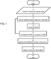
- FIG. 1 is a flowchart diagram of a method suitable for of estimating the likelihood of brain concussion from neurophysiological data, according to various exemplary embodiments of the present invention. It is to be understood that, unless otherwise defined, the operations described hereinbelow can be executed either contemporaneously or sequentially in many combinations or orders of execution. Specifically, the ordering of the flowchart diagrams is not to be considered as limiting. For example, two or more operations, appearing in the following description or in the flowchart diagrams in a particular order, can be executed in a different order (e.g., a reverse order) or substantially contemporaneously. Additionally, several operations described below are optional and may not be executed.
- At least part of the operations can be can be implemented by a data processing system, e.g., a dedicated circuitry or a general purpose computer, configured for receiving the data and executing the operations described below.
- a data processing system e.g., a dedicated circuitry or a general purpose computer, configured for receiving the data and executing the operations described below.
- Computer programs implementing the method of the present embodiments can commonly be distributed to users on a distribution medium such as, but not limited to, a floppy disk, a CD-ROM, a flash memory device and a portable hard drive. From the distribution medium, the computer programs can be copied to a hard disk or a similar intermediate storage medium. The computer programs can be run by loading the computer instructions either from their distribution medium or their intermediate storage medium into the execution memory of the computer, configuring the computer to act in accordance with the method of this invention. All these operations are well-known to those skilled in the art of computer systems.
- the method of the present embodiments can be embodied in many forms. For example, it can be embodied in on a tangible medium such as a computer for performing the method operations. It can be embodied on a computer readable medium, comprising computer readable instructions for carrying out the method operations. In can also be embodied in electronic device having digital computer capabilities arranged to run the computer program on the tangible medium or execute the instruction on a computer readable medium.
- the neurophysiological data to be analyzed can be any data acquired directly from the brain of the subject under investigation.
- the neurophysiological data can be data acquired directly from the brain of a single subject or data acquired directly from multiple brains of respective multiple subjects ( e.g ., a research group), not necessarily simultaneously.
- Analysis of data from multiple brains can be done by performing the operations described below separately for each portion of the data that correspond to a single brain. Yet, some operations can be performed collectively for more than one brain.
- a reference to "subject” or “brain” in the singular form does not necessarily mean analysis of data of an individual subject.
- a reference to “subject” or “brain” in the singular form encompasses also analysis of a data portion which corresponds to one out of several subjects, which analysis can be applied to other portions as well.
- the data can be analyzed immediately after acquisition ("online analysis”), or it can be recorded and stored and thereafter analyzed (“offline analysis”).
- neurophysiological data types suitable for the present invention include, without limitation, electroencephalogram (EEG) data, magnetoencephalography (MEG) data, computer-aided tomography (CAT) data, positron emission tomography (PET) data, magnetic resonance imaging (MRI) data, functional MRI (fMRI) data, ultrasound data, single photon emission computed tomography (SPECT) data, Brain Computer Interface (BCI) data, and data from neuroprostheses at the neural level.
- EEG electroencephalogram
- MEG magnetoencephalography
- CAT computer-aided tomography
- PET positron emission tomography
- MRI magnetic resonance imaging
- fMRI functional MRI
- ultrasound data single photon emission computed tomography
- SPECT single photon emission computed tomography
- BCI Brain Computer Interface
- the data include combination of two or more different types of data.
- the neurophysiological data are associated with signals collected using a plurality of measuring devices respectively placed at a plurality of different locations on the scalp of the subject.
- the data type is preferably EEG or MEG data.
- the measuring devices can include electrodes, superconducting quantum interference devices (SQUIDs), and the like.
- the portion of the data that is acquired at each such location is also referred to as "channel.”
- the neurophysiological data are associated with signals collected using a plurality of measuring devices placed in the brain tissue itself.
- the data type is preferably invasive EEG data, also known as electrocorticography (ECoG) data.
- the neurophysiological data is collected at least before and after the subject has performed a task and/or action.
- the neurophysiological data is collected at least before and after the subject has conceptualized a task and/or action but has not actually performed the task.
- Neurophysiological data which is associated with a task and/or action can be used as event related measures, such as event related potentials (ERPs) or event related fields (ERFs).
- the task and/or action (whether actually performed or conceptualized) is preferably in response to a stimulus or stimuli, and the acquisition of data is synchronized with the stimulus to establish a timeline of the response and extract data features responsively to this timeline.
- the data collection is on-going such that neurophysiological data are collected continuously before, during and after performance or conceptualization of the task and/or action.
- the task/action can be single, serial or on-going.
- An example of an on-going lower-level cognitive task/action includes, without limitation, watching a movie; an example of a single lower-level cognitive task/action includes, without limitation, providing an audible signal (e.g., a simple sound) to the subject; and an example of a serial lower-level cognitive task/action includes, without limitation, playing an audible signal repeatedly. It is appreciated that for a repetitive task the subject may eventually be conditioned and will pay less attention (a process known as habituation), but there still will be a response from the brain.
- An example of a higher-level cognitive task/action includes, without limitation, the so called "Go/NoGo task" in which the subject is requested to push a button if a high pitch sound is heard, wherein if a low pitch sound is heard then the subject is not to push the button.
- This task is known in the art and is used in many cognitive studies.
- Stimulus-response neuropsychological tests include, without limitation, the Stroop task, the Wisconsin card sorting test, and the like; stimulus-only based tests include, without limitation, mismatch negativity, brain-stem-evoked response audiometry (BERA), and the like.
- response-only based tests such as, but not limited to, saccade analysis, movement related potentials (MRP), N-back memory tasks and other working memory tasks, e.g., the Sternberg memory task, the "serial seven" test (counting back from 100 in jumps of seven), the Posner attention tasks and the like.
- the method begins at 10 and optionally and preferably continues to 11 at which the neurophysiological data are received.
- the data can be recorded directly from the subject or it can be received from an external source, such as a computer readable memory medium on which the data are stored.
- the method continues to 12 at which relations between features of the data are determined so as to indentify activity-related features.
- This can be done using any procedure known in the art. For example, procedures as described in International Publication Nos. WO 2007/138579 , WO 2009/069134 , WO 2009/069135 and WO 2009/069136 , can be employed. A detailed description of a procedure suitable for executing 12 according to some embodiments of the present invention is described hereinunder with reference to FIG. 2A .
- the extraction of activity-related features includes multidimensional analysis of the data, wherein the data is analyzed to extract spatial and non-spatial characteristics of the data.
- the spatial characteristics preferably describe the locations from which the respective data were acquired.
- the spatial characteristics can include the locations of the measuring devices (e.g., electrode, SQUID) on the scalp of the subject.
- a source localization procedure which may include, for example, low resolution electromagnetic tomography (LORETA), is employed.
- LORETA low resolution electromagnetic tomography
- a source localization procedure suitable for the present embodiments is described in the aforementioned international publications.
- Other source localization procedure suitable for the present embodiments are found in Greenblatt et al., 2005, " Local Linear Estimators for the Bioelectromagnetic Inverse Problem," IEEE Trans.
- the spatial characteristics estimate locations on the epicortical surface.
- data collected at locations on the scalp of the subject are processed so as to map the scalp potential distribution onto the epicortical surface.
- the technique for such mapping is known in the art and referred to in the literature as Cortical Potential Imaging (CPI) or Cortical Source Density (CSD).
- CPI Cortical Potential Imaging
- CSS Cortical Source Density
- Mapping techniques suitable for the present embodiments are found in Kayser et al., 2006, "Principal Components Analysis of Laplacian Waveforms as a Generic Method for Identifying ERP Generator Patterns: I.
- the spatial characteristics can be represented using a discrete or continuous spatial coordinate system, as desired.
- the coordinate system typically corresponds to the locations of the measuring devices (e.g ., locations on the scalp, epicortical surface, cerebral cortex or deeper in the brain).
- the coordinate system is continuous, it preferably describes the approximate shape of the scalp or epicortical surface, or some sampled version thereof.
- a sampled surface can be represented by a point-cloud which is a set of points in a three-dimensional space, and which is sufficient for describing the topology of the surface.
- the spatial characteristics can be obtained by piecewise interpolation between the locations of the measuring devices. The piecewise interpolation preferably utilizes a smooth analytical function or a set of smooth analytical functions over the surface.
- the non-spatial characteristics are obtained separately for each spatial characteristic.
- the non-spatial characteristics can be obtained separately for each channel.
- the spatial characteristics are continuous, the non-spatial characteristics are preferably obtained for a set of discrete points over the continuum. Typically, this set of discrete points includes at least the points used for the piecewise interpolation, but may also include other points over the sampled version of the surface.
- the non-spatial characteristics preferably include temporal characteristics, which are obtained by segmenting the data according to the time of acquisition.
- the segmentation results in a plurality of data segments each corresponding to an epoch over which the respective data segment was acquired.
- the length of the epoch depends on the temporal resolution characterizing the type f neurophysiological data. For example, for EEG or MEG data, a typical epoch length is approximately 1000 ms.
- non-spatial characteristics can be obtained by data decomposing techniques.
- the decomposition is performed separately for each data segment of each spatial characteristic.
- decomposition is applied, e.g., sequentially to each data segment of this particular channel (e.g., first to the segment that corresponds to the first epoch, then to the segment that correspond to the second epoch and so on).
- Such sequential decomposition is performed for other channels as well.
- the neurophysiological data can be decomposed by identifying a pattern of peaks in the data, or, more preferably by means of waveform analysis, such as, but not limited to, wavelet analysis.
- the peak identification is accompanied by a definition of a spatiotemporal neighborhood of the peak.
- the neighborhood can be defined as a spatial region (two- or three-dimensional) in which the peak is located and/or a time-interval during which the peak occurs.
- both a spatial region and time-interval are defined, so as to associate a spatiotemporal neighborhood for each peak.
- the advantage of defining such neighborhoods is that they provide information regarding the spreading structure of the data over time and/or space.
- the size of the neighborhood (in terms of the respective dimension) can be determined based on the property of the peak. For example, in some embodiments, the size of the neighborhood equals the full width at half maximum (FWHM) of the peak. Other definitions of the neighborhood are not excluded from the scope of the present invention.
- the waveform analysis is preferably accompanied by filtering (e.g., bandpass filtering) such that the wave is decomposed to a plurality of overlapping sets of signal peaks which together make up the waveform.
- filtering e.g., bandpass filtering
- the filters themselves may optionally be overlapping.
- one or more of the following frequency bands can be employed during the filtering: delta band (typically from about 1 Hz to about 4 Hz), theta band (typically from about 3 to about 8 Hz), alpha band (typically from about 7 to about 13 Hz), low beta band (typically from about 12 to about 18 Hz), beta band (typically from about 17 to about 23 Hz), and high beta band (typically from about 22 to about 30 Hz).
- delta band typically from about 1 Hz to about 4 Hz
- theta band typically from about 3 to about 8 Hz
- alpha band typically from about 7 to about 13 Hz
- low beta band typically from about 12 to about 18 Hz
- beta band typically from about 17 to about 23 Hz
- high beta band typically from about 22 to about 30 Hz.
- Higher frequency bands such as, but not limited to, gamma band (typically from about 30 to about 80 Hz), are also contemplated.
- waveform characteristics such as, but not limited to, time (latency), frequency and optionally amplitude are preferably extracted. These waveform characteristics are preferably obtained as discrete values, thereby forming a vector whose components are the individual waveform characteristics. Use of discrete values is advantageous since it reduces the amount of data for further analysis.
- Other reduction techniques such as, but not limited to, statistical normalization (e.g., by means of standard score, or by employing any statistical moment) are also contemplated. Normalization can be used for reducing noise and is also useful when the method is applied to data acquired from more than one subject and/or when the interfaces between the measuring device and the brain vary among different subjects or among different locations for a single subject. For example, statistical normalization can be useful when there is non-uniform impedance matching among EEG electrodes.
- the extraction of characteristics results in a plurality of vectors, each of which includes, as the components of the vector, the spatial characteristics (e.g., the location of the respective electrode or other measuring device), and one or more non-spatial characteristics as obtained from the segmentation and decomposition.
- Each of these vectors is a feature of the data, and any pair of vectors whose characteristics obey some relation (for example, causal relation wherein the two vectors are consistent with flow of information from the location associated with one vector to the location associated with the other vector) constitutes two activity-related features.
- the extracted vectors thus define a multidimensional space.
- the vectors when the components include location, time and frequency, the vectors define a three-dimensional space, and when the components include location, time, frequency and amplitude, the vectors define a four-dimensional space. Higher number of dimensions is not excluded from the scope of the present invention.
- each feature of the data is represented as a point within the multidimensional space defined by the vectors, and each set of activity-related features is represented as a set of points such that any point of the set is within a specific distance along the time axis (also referred to hereinbelow as "latency-difference") from one or more other points in the set.
- a feature of the data is preferably represented as a cluster of discrete points in the aforementioned multidimensional space.
- a cluster of points can also be defined when the analysis is applied to neurophysiological data of a single subject.
- vectors of waveform characteristics are extracted separately for separate stimuli presented to the subject, thereby defining clusters of points within the multidimensional space, where each point within the cluster corresponds to a response to a stimulus applied at a different time.
- the separate stimuli optionally and preferably form a set of repetitive presentations of the same or similar stimulus, or a set of stimuli which are not necessarily identical but are of the same type (e.g., a set of not-necessarily identical visual stimuli). Use of different stimuli at different times is not excluded from the scope of the present invention.
- a cluster contains points that correspond to different subjects as well as points that correspond to a response to a separated stimulus.
- a cluster within the multidimensional space may include up to 5 ⁇ 10 points, each representing a vector of characteristics extracted from one of the data segments.
- the width of a cluster along a given axis of the space describes a size of an activity window for the corresponding data characteristic (time, frequency, etc).
- a data characteristic time, frequency, etc.
- the width of a cluster along the time axis is optionally and preferably used by the method to describe the latency range within which the event occurs across multiple subjects.
- the width of a cluster along the frequency axis can be used for describing the frequency band indicating an occurrence of an event occurring across multiple subjects;
- the widths of a cluster along the location axes e.g., two location axes for data corresponding to a 2D location map, and three location axes for data corresponding to a 3D location map
- the width of a cluster along the amplitude axis can be used to define an amplitude range indicating an occurrence of event across multiple subjects.
- activity-related features can be identified as follows.
- a single cluster along the time axis is preferably identified as representing a unitary event occurring within a time window defined, as stated, by the width of the cluster. This window is optionally and preferably narrowed to exclude some outlier points, thereby redefining the latency range characterizing the respective data feature.
- a pattern extraction procedure is preferably implemented for identifying those clusters which obey connectivity relations thereamongst. Broadly speaking such procedure can search over the clusters for pairs of clusters in which there are connectivity relations between a sufficient number of points between the clusters.
- the pattern extraction procedure can include any type of clustering procedures, including, without limitation, a density-based clustering procedure, a nearest-neighbor-based clustering procedure, and the like.
- a density-based clustering procedure suitable for the present embodiments is described in Cao et al., 2006, "Density-based clustering over an evolving data stream with noise," Proceedings of the Sixth SIAM International Conference on Data Mining. Bethesda, Maryland, p. 328-39 .
- a nearest-neighbor clustering procedure suitable for the present embodiments is described in [ R.O. Duda, P.E. Hart and D.G. Stork, "Pattern Classification” (2nd Edition), A Wiley-Interscience Publication, 2000 ].
- meta-clusters are, therefore, clusters of the identified clusters.
- the meta-clusters are the features of the data, and activity-related features are identified among the meta-clusters.
- FIG. 2A is a flowchart diagram describing a procedure 12 for identifying activity-related features for a group of subjects, according to some embodiments of the present invention.
- Procedure 12 begins at 40 and continues to 41 at which isolated clusters are identified.
- the present embodiments contemplate both subspace clustering, wherein clusters are identified on a particular projection of the multidimensional space, and full-space clustering wherein clusters are identified on the entire multidimensional space. Subspace clustering is preferred from the standpoint of computation time, and full-space clustering is preferred from the standpoint of features generality.
- One representative example of subspace clustering includes identification of clusters along the time axis, separately for each predetermined frequency band and each predetermined spatial location.
- the identification optionally and preferably features a moving time-window with a fixed and predetermined window width.
- a typical window width for EEG data is about 200 ms for the delta band.
- a restriction on a minimal number of points in a cluster is optionally applied so as not to exclude small clusters from the analysis.
- cluster with less than X points, where X equals about 80 % of the subjects in the group are excluded.
- the minimal number of points can be updated during the procedure.
- subspace clustering includes identification of clusters over a space-time subspace, preferably separately for each predetermined frequency band.
- the extracted spatial characteristics are represented using a continuous spatial coordinate system, e.g., by piecewise interpolation between the locations of the measuring devices, as further detailed hereinabove.
- each cluster is associated with a time window as well as a spatial region, wherein the spatial region may or may not be centered at a location of a measuring device.
- at least one cluster is associated with a spatial region which is centered at a location other than a location of a measuring device.
- the space-time subspace is typically three-dimensional with one temporal dimension and two spatial dimensions, wherein each cluster is associated with a time-window and a two-dimensional spatial region over a surface which may correspond, e.g., to the shape of the scalp surface, the epicortical surface and the like. Also contemplated is a four-dimensional space-time space wherein each cluster is associated with a time-window and a three-dimensional spatial region over a volume corresponding, at least in part, to internal brain.
- subspace clustering includes identification of clusters over a frequency-space-time subspace.
- the method instead of searching for clusters separately for each predetermined frequency band, the method allows identification of clusters also at frequencies which are not predetermined.
- the frequency is considered as a continuous coordinate over the subspace.
- the extracted spatial characteristics are represented using a continuous spatial coordinate system.
- each cluster is associated with a time window, a spatial region and a frequency band.
- the spatial region can be two- or three-dimensional as further detailed hereinabove.
- At least one cluster is associated with a spatial region which is centered at a location other than a location of a measuring device, and at least one cluster is associated with a frequency band which includes frequencies of two or more of the delta, theta, alpha, low beta, beta, high beta and gamma bands.
- a cluster can be associated with a frequency band spanning over part of the delta band and part of the theta band, or part of the theta band and part of the alpha band, or part of the alpha band and part of the low beta band, etc.
- Procedure 12 optionally and preferably continues to 42 at which, a pair of clusters is selected.
- the procedure optionally and preferably continues to 43 at which, for each subject that is represented in the selected pair, latency difference (including zero difference) between the corresponding events is optionally calculated.
- the procedure continues to 44 at which a constraint is applied to the calculated latency differences such that latency differences which are outside a predetermined threshold range (e.g., 0-30 ms) are rejected while latency differences which are within the predetermined threshold range are accepted.
- the procedure continues to decision 45 at which the procedure determines whether the number of accepted differences is sufficiently large (i.e., above some number, e.g., above 80 % of the subjects in the group).
- the procedure proceeds to 46 at which the procedure accepts the pair of clusters and identifies it as a pair of activity-related features. If the number of accepted differences is sufficiently large the procedure proceeds to 47 at which the procedure reject the pair. From 46 or 47 the procedure of the present embodiments loops back to 42.
- FIG. 2B An illustrative example for determining relations among the data features and identification of activity-related features is shown in FIG. 2B .
- the illustration is provided in terms of a projection onto a two-dimensional space which includes time and location.
- the present example is for an embodiment in which the spatial characteristics are discrete, wherein the identification of clusters is along the time axis, separately for each predetermined frequency band and each predetermined spatial location.
- the skilled person would know how to adapt the description for the other dimensions, e.g., frequency, amplitude, etc.
- FIG. 2B illustrates a scenario in which data are collected from 6 subjects (or from a single subject, present with 6 stimuli at different times), enumerated 1 through 6.
- Data Segment No For clarity of presentation, different data segments data (e.g., data collected from different subjects, or from the same subject but for stimuli of different times) are separated along a vertical axis denoted "Data Segment No.” For each segment, an open circle represents an event recorded at one particular location (by means of a measuring device, e.g., EEG electrode) denoted "A”, and a solid disk represents an event recorded at another particular location denoted "B".
- a measuring device e.g., EEG electrode
- the time axis represents the latency of the respective event, as measured, e.g., from a time at which the subject was presented with a stimulus.
- the latencies are not shown in FIG. 2B , but one of ordinary skills in the art, provided with the details described herein would know how to add the latencies to the drawing.
- a time window For each of locations A and B, a time window is defined. These time windows, denoted ⁇ t A and ⁇ t B , correspond to the width of the clusters along the time axis and they can be the same or different from one another, as desired. Also defined is a latency difference window ⁇ t AB , between the two unitary events. This window corresponds to the separation along the time axis between the clusters (e.g., between their centers).
- the window ⁇ t AB is illustrated as an interval having a dashed segment and a solid segment. The length of the dashed segment represents the lower bound of the window and the overall length of the interval represents the upper bound of the window.
- ⁇ t A , ⁇ t B and ⁇ t AB are part of the criteria for determining whether to accept the pair of events recorded at A and B as activity-related features.
- a unitary event is defined as a cluster of data points obtained from segment Nos. 1, 2, 4, 5 and 6, and for location B, a unitary event is defined as a cluster of data points obtained from segment Nos. 1-5.
- the latency difference window ⁇ t AB is preferably used for identifying activity-related features.
- a pair of features is accepted as an activity-related pair if (i) each of the features in the pair belongs to a unitary event, and (ii) the corresponding latency difference falls within ⁇ t AB .
- the procedure also accepts pairs corresponding to simultaneous events of the data that occur at two or more different locations. Although such events are not causal with respect to each other (since there is no flow of information between the locations), the corresponding features are marked by the method. Without being bounded to any particular theory, the present inventors consider that simultaneous events of the data are causally related to another event, although not identified by the method. For example, the same physical stimulus can generate simultaneous events in two or more locations in the brain.
- the identified pairs of activity-related features can be treated as elementary patterns which can be used as elementary building blocks for constructing complex patterns within the feature space.
- the method proceeds to 48 at which two or more pairs of activity-related features are joined ( e.g ., concatenated) to form a pattern of more than two features.
- the criterion for the concatenation can be similarity between the characteristics of the pairs, as manifested by the vectors.
- two pairs of activity-related features are concatenated if they have a common feature. Symbolically, this can be formulated as follows: the pairs "A-B" and "B-C" have "B" as a common feature and are concatenated to form a complex pattern A-B-C.
- the concatenated set of features is subjected to a thresholding procedure, for example, when X % or more of the subjects in the group are included in the concatenated set, the set is accepted, and when less than X % of the subjects in the group are included in the concatenated set, the set is rejected.
- a thresholding procedure for example, when X % or more of the subjects in the group are included in the concatenated set, the set is accepted, and when less than X % of the subjects in the group are included in the concatenated set, the set is rejected.
- a typical value for the threshold X is about 80.
- Each pattern of three or more features thus corresponds to a collection of clusters defined such that any cluster of the collection is within a specific latency-difference from one or more other clusters in the collection.
- BNA brain network activity
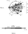
- FIG. 3 is a representative example of a BNA pattern 20 which may be extracted from neurophysiological data, according to some embodiments of the present invention.
- BNA pattern 20 has a plurality of nodes 22, each representing one of the activity-related features.
- a node can represent a particular frequency band (optionally two or more particular frequency bands) at a particular location and within a particular time-window or latency range, optionally with a particular range of amplitudes.
- the BNA pattern is represented as a graph having nodes and edges.
- the BNA pattern includes plurality of discrete nodes, wherein information pertaining to features of the data is represented only by the nodes and information pertaining to relations among the features is represented only by the edges.
- FIG. 3 illustrates BNA pattern 20 within a template 26 of a scalp, allowing relating the location of the nodes to the various lobes of the brain (frontal 28, central 30, parietal 32, occipital 34 and temporal 36 ).
- the nodes in the BNA pattern can be labeled by their various characteristics.
- a color coding or shape coding visualization technique can also be employed, if desired. For example, nodes corresponding to a particular frequency band can be displayed using one color or shape and nodes corresponding to another frequency band can be displayed using another color or shape. In the representative example of FIG. 3 , two colors are presented. Red nodes correspond to Delta waves and green nodes correspond to Theta waves.
- a BNA pattern such as the illustrated pattern 20, can describe brain activity of a single subject or a group or sub-group of subjects.
- a BNA pattern which describes the brain activity of a single subject is referred to herein as a subject-specific BNA pattern, and BNA pattern which describes the brain activity of a group or sub-group of subjects is referred to herein as a group BNA pattern.
- BNA pattern 20 When BNA pattern 20 is a subject-specific BNA pattern, only vectors extracted from data of the respective subject are used to construct the BNA pattern. Thus, each node corresponds to a point in the multidimensional space and therefore represents an activity event in the brain.
- BNA pattern 20 When BNA pattern 20 is a group BNA pattern, some nodes can correspond to a cluster of points in the multidimensional space and therefore represents an activity event which is prevalent in the group or sub-group of subjects. Due to the statistical nature of a group BNA pattern, the number of nodes (referred to herein as the "order") and/or edges (referred to herein as the "size") in a group BNA pattern is typically, but not necessarily, larger than the order and/or size of a subject-specific BNA pattern.
- the group data include, in the present example, two unitary events associated with locations A and B. Each of these events forms a cluster in the multidimensional space.
- each of the clusters referred to herein as clusters A and B, is represented by a node in the group BNA.
- the two clusters A and B are identified as activity-related features since there are some individual points within these clusters that pass the criteria for such relation (the pairs of Subject Nos. 4 and 5, in the present example).
- the nodes corresponding to clusters A and B are connected by an edge.
- a simplified illustration of the resulting group BNA pattern is illustrated in FIG. 2C .
- the group BNA pattern describes brain activity in several subjects, it is typically constructed for a group or sub-group of subjects with some common classification which may pertain to condition, characteristics, affiliation and the like. Such group BNA patterns can be annotated according to the group classification.
- annotated BNA pattern will be used to denote a BNA pattern that is associated with annotation information.
- the annotation information can be stored separately from the BNA pattern ( e.g ., in a separate file on a computer readable medium).
- the annotation information is preferably global annotation wherein the entire BNA pattern is identified as corresponding to a specific brain related disorder or condition.
- the annotation information can pertain to the presence, absence or level of the specific disorder or condition.
- the annotation information pertains to a specific brain related disorder or condition in relation to a treatment applied to the subject.
- a BNA pattern can be annotated as corresponding to a treated brain related disorder.
- Such BNA pattern can also be annotated with the characteristics of the treatment, including dosage, duration, and elapsed time following the treatment.
- a BNA pattern can optionally and preferably be annotated as corresponding to an untreated brain related disorder.
- treatment includes abrogating, substantially inhibiting, slowing or reversing the progression of a condition, substantially ameliorating clinical or aesthetical symptoms of a condition or substantially preventing the appearance of clinical or aesthetical symptoms of a condition.
- Treatment can include any type of intervention, both invasive and noninvasive, including, without limitation, pharmacological, surgical, irradiative, rehabilitative, and the like.
- the BNA pattern can be identified as corresponding to a specific group of individuals (e.g., a specific gender, ethnic origin, age group, etc .), wherein the annotation information pertains to the characteristics of this group of individuals.
- the annotation information includes local annotation wherein nodes at several locations over the BNA pattern are identified as indicative of specific disorder, condition and/or group.
- the nodes in the subject-specific BNA pattern are all based on vectors extracted from data of the respective subject.
- a subject-specific BNA pattern is optionally and preferably constructed by comparing the features and relations among features of the data collected from the respective subject to the features and relations among features of reference data.
- the reference data can include group data and/or data of a single subject, preferably the same subject under analysis, and/or synthetic data generated, e.g., by means of a neurophysiological model.
- the reference data comprise group data
- points and relations among points associated with the subject's data are compared to clusters and relations among clusters associated with the group's data.
- Cluster A does not include a contribution from Subject No. 3
- cluster B does not include a contribution from Subject No. 6, since for these subjects the respective points fail to pass the time-window criterion.
- a subject-specific BNA pattern is constructed for Subject No. 3 it does not include a node corresponding to location A
- a subject-specific BNA pattern is constructed for Subject No. 6 it does not include a node corresponding to location B.
- both locations A and B are represented as nodes in the subject-specific BNA patterns constructed for any of Subject Nos. 1, 2, 4 and 5.
- the corresponding nodes are preferably connected by an edge.
- a simplified illustration of a subject-specific BNA pattern for such a case is shown in FIG. 2D .
- the subject-specific BNA of FIG. 2D is similar to the group BNA of FIG. 2C .
- the order and/or size of the group BNA pattern is, as stated, typically larger than the order and/or size of the subject-specific BNA pattern.
- An additional difference between the subject-specific and group BNA patterns can be manifested by the degree of relation between the activity-related features represented by the edges, as further detailed hereinbelow.
- the corresponding nodes are preferably not connected by an edge.
- a simplified illustration of a subject-specific BNA pattern for such case is shown in FIG. 2E .
- the reference data include data of a single subject
- vectors of waveform characteristics are extracted separately for time-separated stimuli, to define clusters of points where each point within the cluster corresponds to a response to a stimulus applied at a different time, as further detailed hereinabove.
- the procedure for constructing subject-specific BNA pattern in these embodiments is preferably the same as procedure for constructing a group BNA pattern described above. However, since all data are collected from a single subject, the BNA pattern is subject-specific.
- the present embodiments contemplate two types of subject-specific BNA patterns: a first type that describes the association of the particular subject to a group or sub-group of subjects, which is a manifestation of a group BNA pattern for the specific subject, and a second type that describes the data of the particular subject without associating the subject to a group or sub-group of subjects.
- the former type of BNA pattern is referred to herein as an associated subject-specific BNA pattern
- the latter type of BNA pattern is referred to herein as an unassociated subject-specific BNA pattern.
- the analysis is preferably performed on the set of repetitive presentations of a single stimulus, namely on a set of single trials, optionally and preferably before averaging the data and turning it to one single vector of the data.
- group BNA patterns on the other hand, the data of each subject of the group is optionally and preferably averaged and thereafter turned into vectors of the data.
- the unassociated subject-specific BNA pattern is generally unique for a particular subject (at the time the subject-specific BNA pattern is constructed), the same subject may be characterized by more than one associated subject-specific BNA patterns, since a subject may have different associations to different groups.
- a subject may have different associations to different groups.
- a first BNA pattern is an unassociated subject-specific BNA pattern, which, as stated is generally unique for this subject, since it is constructed from data collected only from subject Y.
- a second BNA pattern is an associated subject-specific BNA pattern constructed in terms of the relation between the data of a subject Y to the data of the healthy group.
- a third BNA pattern is an associated subject-specific BNA pattern constructed in terms of the relation between the data of a subject Y to the data of the non-healthy group.
- Each of these BNA patterns are useful for assessing the condition of subject Y.
- the first BNA pattern can be useful, for example, for monitoring changes in the brain function of the subject over time ( e.g ., monitoring brain plasticity or the like) since it allows comparing the BNA pattern to a previously constructed unassociated subject-specific BNA pattern.
- the second and third BNA pattern can be useful for determining the level of association between subject Y and the respective group, thereby determining the likelihood of brain disorder for the subject.
- the reference data used for constructing the subject-specific BNA pattern corresponds to history data previously acquired from the same subject. These embodiments are similar to the embodiments described above regarding the associated subject-specific BNA pattern, except that the BNA pattern is associated to the history of the same subject instead of to a group of subjects.
- the reference data corresponds to data acquired from the same subject at some later time. These embodiments allow investigating whether data acquired at an early time evolve into the data acquired at the later time.
- a particular and non limiting example is the case of several treatment sessions, e.g ., N sessions, for the same subject.
- Data acquired in the first several treatment sessions can be used as reference data for constructing a first associated subject-specific BNA pattern corresponding to mid sessions (e.g ., from session k 2 > k 1 to session k 3 >k 2 ), and data acquired in the last several treatment sessions (e.g., from session k 4 to session N) can be used as reference data for constructing a second associated subject-specific BNA pattern corresponding to the aforementioned mid sessions, where 1 ⁇ k 1 ⁇ k 2 ⁇ k 3 ⁇ k 4 .
- Such two associated subject-specific BNA patterns for the same subject can be used for determining data evolution from the early stages of the treatment to the late stages of the treatment.
- the reference data comprise data synthesized from a neurophysiological model.
- the model can be based on prior knowledge regarding expected spatiotemporal flow patterns among various functional regions in the brain for a particular condition of the brain.
- a neurophysiological model can be constructed by processing training neurophysiological data, collected from a sufficiently large sample size, and employing statistical analysis and/or machine learning techniques to construct a predictive model.
- the sources of the training neurophysiological data can be of any type that provides information regarding neurological activity ion the brain.
- Representative examples include, without limitation, EEG data, MEG data, CAT data, PET data, MRI data, fMRI data, ultrasound data, SPECT data, BCI data, and data from neuroprostheses at the neural level.
- the model is constructed based on combination of two or more different types of data.
- the training set can also include literature data.
- the training set may optionally be compiled from subjects from the different research groups, including, without limitation, at least one control group and at least one target group of subjects with similar behaviors, e.g., pathological actions or activities performed in a specific way due to a pathological condition, or non-pathological actions which the subjects are requested to perform.
- a technique for generating a neurophysiological model suitable for some embodiments of the present invention is found in International Publication No. WO2009/069135 , assigned to the same assignee as the present application.
- model or models that are able to fit the training set can be constructed, and scored, e.g., by a likelihood rating, reflecting the likelihood of the model fitting the training set.
- the model or models that have the highest scores can be selected and used a computerized engine for generating synthetic neurophysiological data to be used as the reference data.
- the selected model(s) receives input regarding the subject under investigation and generate in response synthetic neurophysiological data which are expected to be obtained from such a subject.
- the selected model optionally and preferably receives input pertaining to a classification group to which the subject is expected to belong, and also a request regarding the type of synthetic data which is required as a reference.
- the selected model preferably receive input regarding the classification group to which the subject belong (e.g., age, gender, and type of sport) as well as a request for generating synthetic data which are characteristic for a condition of brain concussion for the particular classification group.
- the synthetic data generated by the neurophysiological is used by the method of the present embodiments as reference data for constructing the associated subject-specific BNA.
- the same subject can have more than one associated subject-specific BNA.
- the model can additionally receive, for example, input regarding the classification group together with a request to generate synthetic data which are characteristic for normal brain function, thus concussion for the particular classification group.
- the latter synthetic data can be used by the method of the present embodiments as reference data for constructing a subject-specific BNA associated with normal brain function.
- Each pair of nodes (or equivalently each edge) in the constructed BNA pattern is optionally and preferably assigned with a connectivity weight pattern, thereby providing a weighted BNA pattern.
- the connectivity weight is represented in FIGs. 2C and 2D and 3 by the thickness of the edges connecting two nodes. For example, thicker edges can correspond to higher weights and thinner edges can correspond to lower weights.
- the connectivity weight comprises a weight index WI calculated based on at least one of the following cluster properties: (i) the number of subjects participating in the corresponding cluster pair, wherein greater weights are assigned for larger number of subjects; (ii) the difference between the number of subjects in each cluster of the pair (referred to as the "differentiation level" of the pair), wherein greater weights are assigned for lower differentiation levels; (iii) the width of the time windows associated with each of the corresponding clusters (see, e.g., ⁇ t A and ⁇ t B in FIG. 2A ), wherein greater weights are assigned for narrower windows; (iv) the latency difference between the two clusters (see ⁇ t AB in FIG.
- the connectivity weight preferably equals the weight index WI as calculated based on the cluster properties.
- the connectivity weight of a pair of nodes is preferably assigned based on the weight index WI as well as one or more subject-specific and pair-specific quantities denoted SI. Representative examples of such quantities are provided below.
- a pair of nodes of the associated subject-specific BNA pattern is assigned with a connectivity weight which is calculated by combining WI with SI.
- the connectivity weight of a pair in the associated subject-specific BNA pattern can be given by WI ⁇ SI.
- the pair can be assigned with more than one connectivity weights, e.g ., WI ⁇ SI 1 , WI ⁇ SI 2 , ..., WI ⁇ SI N , wherein SI 1 , SI 2 , ..., SI N , are N calculated quantities.
- all connectivity weights of a given pair can be combined, e.g., by averaging, multiplying and the like.
- the quantity SI can be, for example, a statistical score characterizing the relation between the subject-specific pair and the corresponding clusters.
- the statistical score can be of any type, including, without limitation, deviation from average, absolute deviation, standard-score and the like.
- the relation for whom the statistical score is calculated can pertain to one or more properties used for calculating the weight index WI, including, without limitation, latency, latency difference, amplitude, frequency and the like.
- a statistical score pertaining to latency or latency difference is referred to herein as a synchronization score and denoted SIs.
- a synchronization score according to some embodiments of the present invention can be obtained by calculating a statistical score for (i) the latency of the point as obtained for the subject (e.g., t (i) A and t (i) B , in the above example) relative to the group-average latency of the corresponding cluster, and/or (ii) the latency difference between two points as obtained for the subject (e.g., ⁇ t ( i ) AB ), relative to the group-average latency difference between the two corresponding clusters.
- a statistical score pertaining to amplitude is referred to herein as an amplitude score and denoted SIa.
- an amplitude score according to some embodiments of the present invention is obtained by calculating a statistical score for the amplitude as obtained for the subject relative to the group-average amplitude of the corresponding cluster.
- a statistical score pertaining to frequency is referred to herein as a frequency score and denoted SIf.
- a frequency score is obtained by calculating a statistical score for the frequency as obtained for the subject relative to the group-average frequency of the corresponding cluster.
- a statistical score pertaining to the location is referred to herein as a location score and denoted SIl. These embodiments are particularly useful in embodiments in which a continuous coordinate system is employed, as further detailed hereinabove.
- a location score according to some embodiments of the present invention is obtained by calculating a statistical score for the location as obtained for the subject relative to the group-average location of the corresponding cluster.
- SI is a synchronization score SIs
- the calculation is optionally and preferably based on the discrete time points matching the spatiotemporal constraints set by the electrode pair ( Time subj ), if such exist.
- the times of these points can are compared to the mean and standard deviation of the times of the discrete points participating in the group pattern ( Time pat ), for each region to provide a regional synchronization score SIs r .
- the synchronization score SIs can then be calculated, for example, by averaging the regional synchronization scores of the two regions in the pair.
- the quantity SI comprises a correlation value between recorded activities.
- the correlation value describes correlation between the activities recorded for the specific subject at the two locations associated with the pair, and in some embodiments the correlation value describes correlation between the activities recorded for the specific subject at any of the locations associated with the pair and the group activities as recorded at the same location. In some embodiments, the correlation value describes causality relations between activities.
- the connectivity weights assigned over the BNA pattern can be calculated as a continuous variable (e.g ., using a function having a continuous range), or as a discrete variable (e.g ., using a function having a discrete range or using a lookup table). In any case, connectivity weights can have more than two possible values.
- the weighted BNA pattern has at least three, or at least four, or at least five, or at least six edges, each of which being assigned with a different connectivity weight.
- the subject-specific BNA pattern can be transmitted to a display device such as a computer monitor, or a printer.
- the BNA pattern can be transmitted to a computer-readable medium.
- the method proceeds to 14 at which the subject-specific BNA pattern (e.g ., pattern 20 ) is compared to a baseline BNA pattern which is specific to the same subject.
- the baseline BNA pattern can be a pattern constructed for the same subjects at a different time for example, an earlier time.
- both the BNA that is constructed at 13 and the baseline BNA describe the association of the particular subject (albeit at different times) to the same group or sub-group of subjects.
- both the constructed and the baseline BNA patterns are subject-specific BNA patterns associated with brain concussion.
- both the constructed and the baseline BNA patterns can be subject-specific BNA patterns associated with normal brain function.
- the method loops back to 12 or 13 so that two or more subject-specific BNA patterns are eventually constructed.
- each subject-specific BNA is constructed based on different reference data or model but using the same neurophysiological data of the subject, and each subject-specific BNA is compared to a different baseline BNA is associated with a different brain condition.
- the method constructs a first associated subject-specific BNA pattern which is associated with brain concussion, and a second subject-specific BNA pattern which is associated with normal brain function.
- Each of the constructed BNA pattern is compared to a respective baseline BNA pattern.
- the first BNA pattern is compared to a baseline BNA pattern associated with brain concussion
- the second BNA pattern is compared to a baseline BNA pattern associated with normal brain function.
- the comparison between BNA patterns is preferably quantitative.
- the comparison between the BNA patterns comprises calculating BNA pattern similarity.
- the BNA pattern similarity is optionally and preferably calculated based on the values of the connectivity weights of the BNA patterns.
- BNA pattern similarity can be obtained by averaging the connectivity weights over the subject-specific BNA pattern.
- the averaging is preferably performed over the BNA pattern separately for each type of connectivity weight.
- one or more of the averages can be combined (e.g., summed, multiplied, averaged, etc. ) to provide a combined BNA pattern similarity.
- a representative of the averages (e.g., the largest) can be defined as the BNA pattern similarity.
- the similarity can be expressed as a continuous or discrete variable.
- the similarity is a non-binary number.
- the method calculates the degree by which the two BNA patterns are similar or dissimilar.
- the similarity can be expressed as percentage, as a non-integer number between 0 and 1 (e.g., 0 corresponding to complete dissimilarity and 1 corresponding to comparison between a BNA pattern and itself), and the like.
- each of the subject-specific BNA patterns are preferably compared to the corresponding baseline BNA pattern.
- the method optionally and preferably selects the pair of BNA patterns which best match each other.
- the method can assign a score to each pair of BNA patterns being compared.
- Such score can be, for example, one or more BNA pattern similarity S, as further detailed hereinabove.
- the invention 52 includes calculation of at least one BNA pattern similarity S, describing the similarity between BNA pattern 20 and the baseline BNA pattern.
- the BNA pattern similarity can be used as a classification score which describes, quantitatively, the membership level of the subject to the respective group. This embodiment is particularly useful when more than one subject-specific BNA patterns are constructed for the same subject using different group data, wherein the classification score can be used to assess the membership level of the subject to each of the groups.
- each contracted subject-specific BNA pattern can be compared to a group BNA pattern in addition or as an alternative to the comparison to the respective subject-specific baseline BNA pattern.
- the method continues to 15 at which the likelihood of brain concussion is assessed responsively to the calculated similarity.
- a concussion index can be calculated based, at least in part, on the obtained similarity.
- the concussion index can be the similarity itself or it can be calculated based on the similarity. For example, when high level of similarity is found between BNA patterns associated with brain concussion, the method can issue a report that there is a high likelihood that the subject has brain concussion.
- both similarity levels can be used for the assessment.
- the likelihood can be transmitted to a computer-readable medium or a display device or a printing device, as desired.
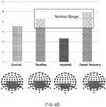
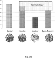
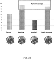
- the concussion index can be presented to the user graphically on a scale-bar. A representative example of such graphical presentation is shown in FIG. 4 .
- the similarity level can optionally and preferably also be used as a prognosis indicator for the particular subject.
- observing the change in similarity level over time can be used as a prognosis indicator.
- the rate of increment can be used as a prognosis indicator.
- the method optionally and preferably extracts 16 prognosis information responsively to the calculated similarity.
- the baseline BNA pattern can also be associated with annotation information pertaining to a treatment, optionally and preferably together with the characteristics of the treatment, e.g., dosage, duration, and elapsed time following the treatment.
- a comparison of the constructed BNA pattern to such type of baseline BNA patterns can provide information regarding the responsiveness of the subject to treatment and/or the efficiency of the treatment for that particular subject. Such comparison can optionally and preferably be used for extracting prognostic information in connection to the specific treatment.
- a BNA pattern that is complementary to such baseline BNA pattern is a BNA pattern that is annotated as corresponding to an untreated brain related disorder.
- the method compares BNA pattern 20 to at least one baseline BNA pattern annotated as corresponding to a treated brain related disorder, and at least one baseline BNA pattern annotated as corresponding to an untreated brain related disorder.
- the prognosis information can be transmitted to a computer-readable medium or a display device or a printing device, as desired.
- the BNA pattern comparison technique of the present embodiments can also be used for inducing improvement in brain function.
- associated subject-specific BNA patterns are constructed for a subject during a higher-level cognitive test, generally in real time.
- the subject can be presented with the constructed BNA patterns or some representation thereof and use them as a feedback. For example, when, as a result of the cognitive action, the BNA pattern of the subject becomes more similar to a characteristic BNA pattern of a healthy group, presentation of such a result to the subject can be used by the subject as a positive feedback.
- the BNA pattern of the subject becomes more similar to a characteristic BNA pattern of a brain-disorder group
- presentation of such a result to the subject can be used by the subject as a negative feedback.
- Real time analysis of BNA patterns in conjunction with neurofeedback can optionally and preferably be utilized to achieve improved cortical stimulation using external stimulating electrodes.
- FIG. 5 is a flowchart diagram of another method suitable for estimating the likelihood of brain concussion from neurophysiological data, according to various exemplary embodiments of the present invention.
- the method begins at 10 and optionally and preferably continues to 11 at which the neurophysiological data are received, as further detailed hereinabove.
- the method continues to 12 at which relations between features of the data are determined so as to indentify activity-related features, and to 13 at which a subject-specific BNA pattern is constructed as further detailed hereinabove.
- the subject-specific BNA pattern is constructed using reference data which is group data or synthetic data.
- the constructed subject-specific BNA is associated with brain concussion.
- the method proceeds to 51 at which the subject-specific BNA pattern (e.g., pattern 20 ) is compared to a group BNA pattern which is annotated as corresponding to brain concussion.
- the comparison can be performed as described above, so as to calculate a BNA pattern similarity.
- the method continues to 52 at which the similarity is compared with a recorded similarity describing comparison between a previously constructed subject-specific BNA pattern of the same subject and the same group BNA pattern.
- the method continues to 53 at which the likelihood of brain concussion is assessed responsively to a difference between the recorded similarity and the calculated similarity.
- the difference between method 50 and method 10 above is that in method 50 the assessment is based on observed changes in the calculated similarity and not necessarily on the change in the subject-specific BNA pattern.
- Another difference is the type of baseline BNA pattern which is employed.
- the baseline BNA pattern is preferably subject-specific.
- the baseline BNA pattern is a group BNA pattern.
- the method can optionally and preferably loop back to 12 or 13 to construct another subject-specific BNA pattern.
- the method can construct 13 a subject-specific BNA pattern which is associated with normal brain function and compare it 51 to a group BNA pattern which is annotated as corresponding to normal brain function to provide a second similarity level.
- the method can then compare 52 the second similarity with a respective second recorded similarity.
- the assessment is based also on the difference between the second recorded similarity and the second calculated similarity. For example, when the similarity that correspond to brain concussion is increased with time and the similarity that correspond to normal brain function is decreased with time, the method can assess that it is likely that the subject is suffering from concussion.
- Method 50 optionally and preferably continues to 16 at which prognosis information is extracted responsively to the calculated similarities, as further detailed hereinabove.
- the method ends at 57.
- Methods 10 and 50 can also be combined.
- the subject-specific is compared both to a subject-specific baseline and to a group annotated baseline. Each comparison provides further assessment regarding the likelihood of brain concussion. All the obtained assessments can be transmitted to a computer-readable medium or a display device or a printing device, as desired.
- a system for analyzing neurophysiological data comprises a data processor, e.g., a dedicated circuitry or a general purpose computer, configured for receiving the neurophysiological data, and executing at least some of the operations described herein.
- a data processor e.g., a dedicated circuitry or a general purpose computer, configured for receiving the neurophysiological data, and executing at least some of the operations described herein.
- a method of assessing a likelihood of attention deficit hyperactivity disorder comprises: identifying activity-related features in neurophysiological data acquired from the brain of a subject, constructing a BNA pattern, and calculating a BNA pattern similarity describing a comparison between the constructed BNA pattern and a baseline ADHD BNA pattern.
- the identification of the activity-related features and/or the construction of BNA pattern can be done as described above with respect to the method for estimating the likelihood of brain concussion.
- the identification of the activity-related features and/or the construction of BNA pattern can be according to the teachings of PCT Application No. PCT/IL2011/000055 .
- the baseline ADHD BNA pattern has nodes representing event related potentials, predominantly at one or more frequency bands selected from the group consisting of delta, theta and alpha frequency bands, at a plurality of frontocentral locations within a characteristic time window of from about 100 ms to about 200 ms.
- the baseline ADHD BNA pattern has nodes representing event related potentials, predominantly at the delta frequency band at a plurality of occipital, parietal and frontocentral locations within a characteristic time window of from about 300 ms to about 600 ms.
- the BNA similarity between the constructed BNA pattern and the baseline ADHD BNA pattern can be used for assessing the likelihood. For example, a BNA pattern similarity which is above a predetermined threshold can indicates a likelihood of the subject having ADHD.
- the likelihood is optionally and preferably extracted by determining an ADHD index based, at least in part, on the similarity between the constructed BNA pattern and the baseline ADHD BNA pattern.
- the ADHD index can be the similarity itself or it can be calculated based on the similarity.
- the brain-disorder index can be presented to the user graphically on a scale-bar.
- a representative example of such graphical presentation for the case of ADHD is shown in FIG. 38.
- compositions, method or structure may include additional ingredients, steps and/or parts, but only if the additional ingredients, steps and/or parts do not materially alter the basic and novel characteristics of the claimed composition, method or structure.
- a compound or “at least one compound” may include a plurality of compounds, including mixtures thereof.
- range format is merely for convenience and brevity and should not be construed as an inflexible limitation on the scope of the invention. Accordingly, the description of a range should be considered to have specifically disclosed all the possible subranges as well as individual numerical values within that range. For example, description of a range such as from 1 to 6 should be considered to have specifically disclosed subranges such as from 1 to 3, from 1 to 4, from 1 to 5, from 2 to 4, from 2 to 6, from 3 to 6 etc., as well as individual numbers within that range, for example, 1, 2, 3, 4, 5, and 6. This applies regardless of the breadth of the range.
- This example describes a model of a model for cognitive impairment brought upon by concussion.
- the model is based on administering scopolamine to healthy subjects.
- Subjects were administered with Scopolamine 0.4 mg, and a placebo drug.
- Two group BNA patterns (one BNA pattern for the placebo group and one BNA pattern for the scopolamine group), and several subject-specific BNA patterns were constructed according to the teachings of the present embodiments.
- the subjects were requested to respond to auditory target stimuli that occur infrequently and irregularly within a series of standard stimuli.
- the standard stimulus was in the form of a 1000 Hz tone
- the target stimulus was in the form of a 2000 Hz tone.
- the intervals between two successive stimuli were 1.5 seconds.
- Each subject was exposed to a series of stimuli, of which 80% were standard stimuli and 10% were target stimuli. The additional 10% were background sounds (referred to as "novel stimuli").
- each subject was requested to memorize an image of a human face (referred to as the "cue"). Two seconds later, the subject was again presented with an image of a human face (referred to as the "probe") and was asked to determine whether the probe matches the cue.
- the cue an image of a human face
- the tests and data acquisitions were performed in three time points (i) immediately following administration of placebo, (ii) one hour after administration of 0.4 mg of scopolamine, and (iii) two weeks afterwards, allowing complete washout of the drug.
- the BNA constructed from data acquired following administration of placebo was used as the baseline BNA.
- the effect of the drug is temporary, thus allowing the present inventors to simulate a concussion episode (when the pharmacokinectics of the drug are at peak level) and after recovery (when the drug has already washed out from the subject).
- FIGs. 6A-C show results corresponding to three different subjects. Data were collected during the oddball test.
- Each of FIGs. 6A-C shows a group baseline BNA pattern annotated as normal, and two subject-specific BNA patterns acquired at time points (ii) and (iii). Also shown is the BNA pattern of the control group.
- the bar graph shows the similarity levels to the baseline.
- the normal range is indicated as a rectangle on the bar graph. More specifically, the rectangle denotes the minimal important difference (MID), which is calculated from the normal group data.
- MID minimal important difference
- FIGs. 7A-C show results of experiments performed for the same three subjects. Data were collected during working memory test. Each of FIGs. 7A-C shows a group baseline BNA pattern annotated as normal, and two subject-specific BNA patterns acquired at time points (ii) and (iii). Also shown is the BNA pattern of the control group. The bar graph shows the similarity levels to the baseline. The normal range is indicated as a rectangle on the bar graph as described above with respect to FIGs. 6A-C .
- the similarity level to the normal baseline is reduced for the impaired condition, indicating that the likelihood of brain concussion is high.
- This example demonstrates that ability of the present embodiments to assess the likelihood of brain concussion.
Claims (15)
- Procédé d'estimation de la probabilité d'une commotion cérébrale, à partir de données neurophysiologiques acquises à partir du cerveau du sujet, comprenant :l'utilisation d'une unité de traitement de données pour :caractérisé en ce que :l'identification (12) des caractéristiques liées à une activité dans lesdites données ;la construction (13) d'un profil d'activité de réseau cérébral (BNA) spécifique du sujet (20), comportant une pluralité de noeuds (22), dans lequel chaque noeud (22) représente une caractéristique desdites caractéristiques liées à une activité,à chaque paire de noeuds est affecté un poids de connectivité ; etl'unité de traitement de données est également utilisée pour :le calcul d'une similarité de profil BNA décrivant une comparaison (14) entre ledit profil BNA construit et un profil BNA de base qui est spécifique du sujet ; etl'évaluation (15) de la probabilité d'une commotion cérébrale en réponse à ladite similarité de profil BNA.
- Procédé selon la revendication 1, dans lequel ledit profil BNA de base (20) est fondé sur un profil BNA de groupe, choisi dans le groupe constitué d'un profil BNA de groupe caractérisant un groupe de sujets identifiés comme ayant des fonctions cérébrales normales, et un profil BNA de groupe caractérisant un groupe de sujets identifiés comme ayant une commotion cérébrale.
- Procédé selon la revendication 1, comprenant en outre la répétition de ladite construction (13) de BNA spécifique du sujet et dudit calcul (51) de similarité de profil BNA au moins une fois, dans lequel chaque BNA spécifique du sujet (20) est construite sur la base de données ou d'un modèle de référence différent(es), mais à l'aide des mêmes données neurophysiologiques du sujet, dans lequel chaque BNA spécifique du sujet (20) est comparée (14) à un profil BNA de base qui est associé à un état cérébral différent, et dans lequel ladite évaluation (15) est effectuée en réponse à au moins deux similarités de profil BNA.
- Procédé selon la revendication 3, dans lequel au moins un profil BNA de base (20) caractérise un groupe de sujets identifiés comme ayant des fonctions cérébrales normales, et au moins un profil BNA de base (20) caractérise un groupe de sujets identifiés comme ayant une commotion cérébrale.
- Procédé selon l'une quelconque des revendications 1 à 4, comprenant en outre la détermination d'un indice de commotion (Icommotion) sur la base d'au moins ladite similarité de profil BNA.
- Procédé selon l'une quelconque des revendications 1 à 5, comprenant en outre la construction de plusieurs profils BNA (20) correspondant à des intervalles de temps différents, et l'affichage desdits profils BNA sur un axe de temps.
- Procédé selon l'une quelconque des revendications 1 à 6, comprenant en outre l'extraction d'informations pronostiques (16) concernant un état cérébral, en réponse au moins à ladite similarité de profil BNA.
- Procédé selon l'une quelconque des revendications 1 à 7, dans lequel ladite identification (12) desdites caractéristiques liées à une activité comprend l'identification de caractéristiques et de relations parmi des caractéristiques dans les données neurophysiologiques du sujet, et la comparaison desdites caractéristiques et desdites relations parmi des caractéristiques à des caractéristiques et des relations parmi des caractéristiques de données neurophysiologiques de référence, de préférence dans lequel lesdites données neurophysiologiques de référence correspondent à des données sélectionnées dans le groupe constitué de données acquises à partir d'un groupe ou d'un sous-groupe de sujets, de données d'antécédents précédemment acquises à partir du même sujet, de données synthétisées à partir d'un modèle neurophysiologique.
- Procédé selon l'une quelconque des revendications 1 à 8, dans lequel lesdits noeuds (22) représentent des groupes de vecteurs de caractéristiques de données, et dans lequel ledit poids de connectivité comprend un indice de poids calculé sur la base d'au moins une propriété de groupe de vecteurs choisie dans le groupe constitué de : (i) un nombre de vecteurs dans une paire correspondante de groupes ; (ii) une variabilité parmi des nombres de vecteurs dans ladite paire correspondante de groupes ; (iii) une largeur de fenêtres de temps associées à chaque groupe de ladite paire correspondante de groupes ; (iv) une différence de latence séparant ladite paire correspondante de groupes ; (v) une amplitude de signal associé à ladite paire correspondante de groupes ; (vi) une fréquence de signal associé à ladite paire correspondante de groupes ; et (vii) la largeur d'une fenêtre spatiale définissant lesdits groupes.
- Procédé selon l'une quelconque des revendications 1 à 9, dans lequel lesdites données neurophysiologiques comprennent des données acquises avant, pendant et/ou après un traitement.
- Procédé d'estimation de la probabilité d'une commotion cérébrale, à partir de données neurophysiologiques acquises à partir du cerveau du sujet, comprenant :l'utilisation d'une unité de traitement de données pour :caractérisé en ce que :l'identification (12) des caractéristiques liées à une activité dans lesdites données ;la construction (13) d'un premier profil d'activité de réseau cérébral (BNA) spécifique du sujet, comportant une pluralité de noeuds (20), dans lequel chaque noeud représente une caractéristique desdites caractéristiques liées à une activité,à chaque paire de noeuds (20) est affecté un poids de connectivité, ledit profil BNA spécifique du sujet étant associé à une commotion cérébrale ; etl'unité de traitement de données est également utilisée pour :le calcul (51) d'une première similarité de profil BNA décrivant une comparaison entre ledit premier profil BNA et un premier profil BNA de base noté comme correspondant à une commotion cérébrale ;la comparaison (52) de ladite similarité à une première similarité enregistrée décrivant une comparaison entre un profil BNA spécifique du sujet, précédemment construit, du sujet et ledit premier profil BNA de base ; etl'évaluation de la probabilité (53) d'une commotion cérébrale en réponse à une différence entre ladite similarité enregistrée et ladite similarité calculée.
- Procédé selon la revendication 11, comprenant en outre :la construction (13) d'un second profil BNA spécifique du sujet, associé à des fonctions cérébrales normales ;le calcul (51) d'une seconde similarité de profil BNA décrivant une comparaison entre ledit second profil BNA et un second profil BNA de base noté comme correspondant à des fonctions cérébrales normales ; etla comparaison (52) de ladite seconde similarité à une seconde similarité enregistrée décrivant une comparaison entre un profil BNA spécifique du sujet, précédemment construit, du sujet et ledit second profil BNA de base ;dans lequel ladite évaluation (53) est effectuée en réponse également à une différence entre ladite seconde similarité enregistrée et ladite seconde similarité calculée.
- Procédé selon l'une quelconque des revendications 1 à 12, comprenant en outre l'acquisition (11) desdites données neurophysiologiques à partir du cerveau du sujet, avant, pendant et/ou après que le sujet effectue ou conçoit la réalisation d'une tâche sélectionnée dans le groupe constitué d'une tâche cognitive de bas niveau et d'une tâche cognitive de haut niveau.
- Système destiné à estimer la probabilité d'une commotion cérébrale, comprenant une unité de traitement de données conçue pour recevoir des données neurophysiologiques, et à exécuter le procédé selon l'une quelconque des revendications 1 à 12.
- Produit logiciel comprenant un support lisible par ordinateur sur lequel des instructions de programme sont stockées, lesquelles instructions, lorsqu'elles sont lues par une unité de traitement de données, amènent l'unité de traitement de données à recevoir des données neurophysiologiques et à exécuter le procédé selon l'une quelconque des revendications 1 à 12.
Applications Claiming Priority (2)
| Application Number | Priority Date | Filing Date | Title |
|---|---|---|---|
| US201161509651P | 2011-07-20 | 2011-07-20 | |
| PCT/IL2012/050262 WO2013011515A1 (fr) | 2011-07-20 | 2012-07-19 | Procédé et système pour estimer une commotion cérébrale |
Publications (2)
| Publication Number | Publication Date |
|---|---|
| EP2734107A1 EP2734107A1 (fr) | 2014-05-28 |
| EP2734107B1 true EP2734107B1 (fr) | 2017-05-24 |
Family
ID=46727279
Family Applications (1)
| Application Number | Title | Priority Date | Filing Date |
|---|---|---|---|
| EP12750826.5A Not-in-force EP2734107B1 (fr) | 2011-07-20 | 2012-07-19 | Procédé et système pour estimer une commotion cérébrale |
Country Status (10)
| Country | Link |
|---|---|
| US (1) | US9839392B2 (fr) |
| EP (1) | EP2734107B1 (fr) |
| JP (1) | JP6209514B2 (fr) |
| CN (1) | CN103917159B (fr) |
| AU (1) | AU2012285379B2 (fr) |
| BR (1) | BR112014001347A2 (fr) |
| CA (1) | CA2841422A1 (fr) |
| IL (1) | IL230502B (fr) |
| RU (1) | RU2678364C2 (fr) |
| WO (1) | WO2013011515A1 (fr) |
Families Citing this family (40)
| Publication number | Priority date | Publication date | Assignee | Title |
|---|---|---|---|---|
| US9895077B2 (en) | 2010-01-18 | 2018-02-20 | Elminda Ltd. | Method for diagnosing a brain related disorder using brain network activity patterns |
| WO2013011515A1 (fr) | 2011-07-20 | 2013-01-24 | Elminda Ltd. | Procédé et système pour estimer une commotion cérébrale |
| JP6146760B2 (ja) * | 2012-02-28 | 2017-06-14 | 国立研究開発法人産業技術総合研究所 | 序列化装置、序列化方法及びプログラム |
| WO2014076698A1 (fr) * | 2012-11-13 | 2014-05-22 | Elminda Ltd. | Analyse de données neurophysiologiques utilisant un morcellement spatio-temporel |
| DE102012111733A1 (de) * | 2012-12-03 | 2014-06-05 | Klaus Glaunsinger | Verfahren und Vorrichtung zur Überprüfung der Validität von Reaktionszeiten einer Person |
| US20140163408A1 (en) * | 2012-12-10 | 2014-06-12 | Ideal Innovations Incorporated | System for analyzing mental and behavioral correlations |
| US9717459B2 (en) | 2013-03-04 | 2017-08-01 | Anne Bibiana Sereno | Touch sensitive system and method for cognitive and behavioral testing and evaluation |
| EP3068295A4 (fr) | 2013-11-13 | 2017-07-19 | Elminda Ltd. | Procédé et système de gestion de la douleur |
| WO2015089416A1 (fr) * | 2013-12-12 | 2015-06-18 | Cornell University | Inhibiteurs de la prolylhydroxylase/atf4 pour le traitement des lésions cellulaires neuronales |
| CA2961451A1 (fr) * | 2014-09-28 | 2016-03-31 | Elminda Ltd. | Configuration d'outil de stimulation cerebrale |
| US9107595B1 (en) * | 2014-09-29 | 2015-08-18 | The United States Of America As Represented By The Secretary Of The Army | Node excitation driving function measures for cerebral cortex network analysis of electroencephalograms |
| US10667737B2 (en) * | 2015-03-23 | 2020-06-02 | International Business Machines Corporation | Monitoring a person for indications of a brain injury |
| EP3310261A4 (fr) | 2015-06-19 | 2019-01-23 | Neural Analytics, Inc. | Sonde doppler transcrânienne |
| CN108778140A (zh) | 2016-01-05 | 2018-11-09 | 神经系统分析公司 | 用于确定临床指征的系统和方法 |
| US10617388B2 (en) | 2016-01-05 | 2020-04-14 | Neural Analytics, Inc. | Integrated probe structure |
| US11589836B2 (en) | 2016-01-05 | 2023-02-28 | Novasignal Corp. | Systems and methods for detecting neurological conditions |
| KR101835402B1 (ko) * | 2016-02-18 | 2018-03-08 | 연세대학교 원주산학협력단 | 뇌 네트워크 기반 뇌 손상 정도 분석방법 및 이를 이용한 장치 |
| US20170347905A1 (en) * | 2016-06-02 | 2017-12-07 | Graham Boulton | Brain activity monitoring, supporting mental state development and training |
| WO2017214356A1 (fr) | 2016-06-08 | 2017-12-14 | The Trustees Of Columbia University In The City Of New York | Systèmes et procédés de diagnostic de commotion en temps réel par surveillance d'activité d'un électroencéphalogramme |
| AU2017305520B2 (en) * | 2016-08-04 | 2022-07-28 | The General Hospital Corporation | System and method for detecting acute brain function impairment |
| EP3532162A1 (fr) * | 2016-10-25 | 2019-09-04 | Brainsway Ltd | Appareil et procédés pour prédire un résultat de thérapie |
| JP7393947B2 (ja) * | 2017-05-22 | 2023-12-07 | ジェネテシス エルエルシー | 生体電磁界における異常の機械識別 |
| US11410756B2 (en) * | 2017-07-28 | 2022-08-09 | Google Llc | System and method for predicting and summarizing medical events from electronic health records |
| WO2019060298A1 (fr) | 2017-09-19 | 2019-03-28 | Neuroenhancement Lab, LLC | Procédé et appareil de neuro-activation |
| KR20190059377A (ko) * | 2017-11-23 | 2019-05-31 | 주식회사 아이메디신 | 뇌파 분석을 통한 외상성 뇌손상 평가 시스템 및 방법 |
| KR20190059364A (ko) * | 2017-11-23 | 2019-05-31 | 주식회사 아이메디신 | 뇌파 분석을 통한 뇌 나이 추정 방법 및 시스템 |
| KR20190059376A (ko) * | 2017-11-23 | 2019-05-31 | 주식회사 아이메디신 | 뇌파를 통한 뇌 인지기능 평가 플랫폼 및 방법 |
| US11717686B2 (en) | 2017-12-04 | 2023-08-08 | Neuroenhancement Lab, LLC | Method and apparatus for neuroenhancement to facilitate learning and performance |
| US11478603B2 (en) | 2017-12-31 | 2022-10-25 | Neuroenhancement Lab, LLC | Method and apparatus for neuroenhancement to enhance emotional response |
| US11364361B2 (en) | 2018-04-20 | 2022-06-21 | Neuroenhancement Lab, LLC | System and method for inducing sleep by transplanting mental states |
| WO2020056418A1 (fr) | 2018-09-14 | 2020-03-19 | Neuroenhancement Lab, LLC | Système et procédé d'amélioration du sommeil |
| JP2022505676A (ja) * | 2018-10-23 | 2022-01-14 | ブラックソーン セラピューティクス インコーポレイテッド | 患者のスクリーニング、診断、及び層別化のためのシステム及び方法 |
| WO2020139108A1 (fr) * | 2018-12-27 | 2020-07-02 | Общество с ограниченной ответственностью "Нейроботикс" | Procédé pour mener des recherches cognitives en utilisant un système de neurovisualisation et un mécanisme de liaison retour |
| JP7276354B2 (ja) * | 2018-12-27 | 2023-05-18 | 株式会社村田製作所 | 認知能力検出装置、および、認知能力検出システム |
| US11786694B2 (en) | 2019-05-24 | 2023-10-17 | NeuroLight, Inc. | Device, method, and app for facilitating sleep |
| RU2712704C1 (ru) * | 2019-09-06 | 2020-01-30 | Общество с ограниченной ответственностью "ИЛИАН" | Способ улучшения выявленных нарушений когнитивных функций и машиночитаемый носитель |
| CN112315456B (zh) * | 2020-10-07 | 2022-02-11 | 南京理工大学 | 基于跳接注意力机制的人体动作预测方法 |
| CN114129163B (zh) * | 2021-10-22 | 2023-08-29 | 中央财经大学 | 基于脑电信号的多视图深度学习的情绪分析方法和系统 |
| CN115423048B (zh) * | 2022-11-03 | 2023-04-25 | 山东大学 | 一种基于模式相似性的交通流量异常检测方法及系统 |
| CN116458898A (zh) * | 2023-03-31 | 2023-07-21 | 广东工业大学 | 一种帕金森病抑郁症特征提取方法及系统 |
Family Cites Families (30)
| Publication number | Priority date | Publication date | Assignee | Title |
|---|---|---|---|---|
| SU1386910A1 (ru) * | 1986-05-16 | 1988-04-07 | Рижский Медицинский Институт | Способ прогнозировани течени патологического процесса у детей при сотр сении головного мозга |
| US6175422B1 (en) | 1991-01-31 | 2001-01-16 | Texas Instruments Incorporated | Method and apparatus for the computer-controlled manufacture of three-dimensional objects from computer data |
| EP1009614A4 (fr) | 1997-06-13 | 2004-04-21 | Massachusetts Inst Technology | Couches de poudre deposees par jet et formation de lits de poudre fine a l'aide de celles-ci |
| US6622036B1 (en) | 2000-02-09 | 2003-09-16 | Cns Response | Method for classifying and treating physiologic brain imbalances using quantitative EEG |
| AUPP354898A0 (en) | 1998-05-15 | 1998-06-11 | Swinburne Limited | Mass communication assessment system |
| US6266554B1 (en) | 1999-02-12 | 2001-07-24 | Cardiac Pacemakers, Inc. | System and method for classifying cardiac complexes |
| US7403814B2 (en) | 2001-05-04 | 2008-07-22 | University Of Virginia Patent Foundation | Method, apparatus, and computer program product for assessment of attentional impairments |
| US10683494B2 (en) * | 2001-11-01 | 2020-06-16 | Pthera LLC | Enhanced stem cell therapy and stem cell production through the administration of low level light energy |
| US8190248B2 (en) * | 2003-10-16 | 2012-05-29 | Louisiana Tech University Foundation, Inc. | Medical devices for the detection, prevention and/or treatment of neurological disorders, and methods related thereto |
| US20050165327A1 (en) * | 2004-01-28 | 2005-07-28 | Thibault Lawrence E. | Apparatus and method for detecting the severity of brain function impairment |
| US20050177058A1 (en) | 2004-02-11 | 2005-08-11 | Nina Sobell | System and method for analyzing the brain wave patterns of one or more persons for determining similarities in response to a common set of stimuli, making artistic expressions and diagnosis |
| CA2556210A1 (fr) * | 2004-02-13 | 2005-09-01 | Georgia Tech Research Corporation | Controle avec affichage pour recherche de commotions et de lesions traumatiques legeres du cerveau |
| WO2005087314A1 (fr) * | 2004-03-11 | 2005-09-22 | Advanced Neuromodulation Systems, Inc. | Systeme et procede de stimulation du cerveau |
| WO2006034305A2 (fr) * | 2004-09-21 | 2006-03-30 | University Of Florida Research Foundation, Inc. | Methode de stimulation cerebrale profonde a conducteurs multiples |
| BRPI0608448A2 (pt) | 2005-03-04 | 2009-12-29 | Mentis Cura Ehf | método e um sistema para avaliar condições neurológicas |
| US7720530B2 (en) * | 2005-08-02 | 2010-05-18 | Brainscope Company, Inc. | Field-deployable concussion detector |
| US7904144B2 (en) * | 2005-08-02 | 2011-03-08 | Brainscope Company, Inc. | Method for assessing brain function and portable automatic brain function assessment apparatus |
| CA2644601A1 (fr) | 2006-03-03 | 2007-09-07 | Mentis Cura Ehf. | Methode et appareillage de construction et d'utilisation d'un outil de reference engendrant un signal d'aide au diagnostic indiquant l'etat medical d'un patient. |
| WO2007138579A2 (fr) | 2006-05-25 | 2007-12-06 | Elminda Ltd. | Reconnaissance de schémas spatiotemporels neuropsychologiques |
| EP2037803A2 (fr) | 2006-07-06 | 2009-03-25 | Regents Of The University Of Minnesota | Analyse des motifs du cerveau à l'aide de mesures temporales |
| JP2008098280A (ja) | 2006-10-10 | 2008-04-24 | Shinano Kenshi Co Ltd | 電子部品立体成形装置 |
| US20140214730A9 (en) | 2007-02-05 | 2014-07-31 | Goded Shahaf | System and method for neural modeling of neurophysiological data |
| JP4145344B1 (ja) * | 2007-10-18 | 2008-09-03 | 株式会社脳機能研究所 | 脳活動測定装置 |
| US20110004412A1 (en) * | 2007-11-29 | 2011-01-06 | Elminda Ltd. | Clinical applications of neuropsychological pattern analysis and modeling |
| EP2227138A4 (fr) | 2007-11-29 | 2015-10-14 | Elminda Ltd | Analyse fonctionnelle de données neurophysiologiques |
| US20090264785A1 (en) * | 2008-04-18 | 2009-10-22 | Brainscope Company, Inc. | Method and Apparatus For Assessing Brain Function Using Diffusion Geometric Analysis |
| CA2666010A1 (fr) | 2008-05-14 | 2009-11-14 | The Hospital For Sick Children | Methodes basees sur les fluctuations de synchronisation corticale |
| US8364254B2 (en) * | 2009-01-28 | 2013-01-29 | Brainscope Company, Inc. | Method and device for probabilistic objective assessment of brain function |
| US9895077B2 (en) | 2010-01-18 | 2018-02-20 | Elminda Ltd. | Method for diagnosing a brain related disorder using brain network activity patterns |
| WO2013011515A1 (fr) | 2011-07-20 | 2013-01-24 | Elminda Ltd. | Procédé et système pour estimer une commotion cérébrale |
-
2012
- 2012-07-19 WO PCT/IL2012/050262 patent/WO2013011515A1/fr active Application Filing
- 2012-07-19 JP JP2014520791A patent/JP6209514B2/ja not_active Expired - Fee Related
- 2012-07-19 RU RU2014105665A patent/RU2678364C2/ru not_active IP Right Cessation
- 2012-07-19 CA CA2841422A patent/CA2841422A1/fr not_active Abandoned
- 2012-07-19 US US14/233,788 patent/US9839392B2/en active Active
- 2012-07-19 BR BR112014001347A patent/BR112014001347A2/pt not_active Application Discontinuation
- 2012-07-19 EP EP12750826.5A patent/EP2734107B1/fr not_active Not-in-force
- 2012-07-19 AU AU2012285379A patent/AU2012285379B2/en not_active Ceased
- 2012-07-19 CN CN201280045473.2A patent/CN103917159B/zh not_active Expired - Fee Related
-
2014
- 2014-01-16 IL IL230502A patent/IL230502B/en active IP Right Grant
Non-Patent Citations (1)
| Title |
|---|
| None * |
Also Published As
| Publication number | Publication date |
|---|---|
| RU2014105665A (ru) | 2015-08-27 |
| CN103917159A (zh) | 2014-07-09 |
| US9839392B2 (en) | 2017-12-12 |
| BR112014001347A2 (pt) | 2017-07-18 |
| JP2014525787A (ja) | 2014-10-02 |
| RU2678364C2 (ru) | 2019-01-28 |
| US20140163328A1 (en) | 2014-06-12 |
| JP6209514B2 (ja) | 2017-10-04 |
| CN103917159B (zh) | 2017-02-15 |
| AU2012285379B2 (en) | 2017-04-13 |
| WO2013011515A1 (fr) | 2013-01-24 |
| AU2012285379A1 (en) | 2014-02-06 |
| EP2734107A1 (fr) | 2014-05-28 |
| IL230502B (en) | 2018-01-31 |
| IL230502A0 (en) | 2014-03-31 |
| WO2013011515A8 (fr) | 2013-03-28 |
| CA2841422A1 (fr) | 2013-01-24 |
Similar Documents
| Publication | Publication Date | Title |
|---|---|---|
| EP2734107B1 (fr) | Procédé et système pour estimer une commotion cérébrale | |
| US11583217B2 (en) | Neurophysiological data analysis using spatiotemporal parcellation | |
| US9713433B2 (en) | Method and system for managing pain | |
| EP3197350B1 (fr) | Configuration d'outil de stimulation cérébrale | |
| US9895077B2 (en) | Method for diagnosing a brain related disorder using brain network activity patterns | |
| US9826914B2 (en) | Functional analysis of neurophysiological data | |
| Lodder et al. | Automated EEG analysis: characterizing the posterior dominant rhythm | |
| Gallego-Jutgla et al. | A theta-band EEG based index for early diagnosis of Alzheimer's disease | |
| Arbabshirani et al. | Functional network connectivity during rest and task: comparison of healthy controls and schizophrenic patients | |
| San-Martin et al. | A method for diagnosis support of mild cognitive impairment through EEG rhythms source location during working memory tasks | |
| Azami et al. | Evaluation of resting-state magnetoencephalogram complexity in Alzheimer's disease with multivariate multiscale permutation and sample entropies | |
| US20220047204A1 (en) | Methods, Computer-Readable Media and Devices for Producing an Index | |
| Fickling | Technical development of the brain vital signs framework as an objective and practical test for concussion | |
| Jedynak et al. | Intermodal consistency of whole-brain connectivity and signal propagation delays | |
| Acosta | An Update to the Boston EEG Automated Processing Pipeline Kalman Detrend Step and an Examination of Mu Suppression | |
| Ince et al. | Schizophrenia classification using working memory MEG ERD/ERS patterns | |
| Hsieh | A Graph Theoretical Analysis of Seizure Initiation |
Legal Events
| Date | Code | Title | Description |
|---|---|---|---|
| PUAI | Public reference made under article 153(3) epc to a published international application that has entered the european phase |
Free format text: ORIGINAL CODE: 0009012 |
|
| 17P | Request for examination filed |
Effective date: 20140128 |
|
| AK | Designated contracting states |
Kind code of ref document: A1 Designated state(s): AL AT BE BG CH CY CZ DE DK EE ES FI FR GB GR HR HU IE IS IT LI LT LU LV MC MK MT NL NO PL PT RO RS SE SI SK SM TR |
|
| DAX | Request for extension of the european patent (deleted) | ||
| 17Q | First examination report despatched |
Effective date: 20150504 |
|
| GRAP | Despatch of communication of intention to grant a patent |
Free format text: ORIGINAL CODE: EPIDOSNIGR1 |
|
| RIC1 | Information provided on ipc code assigned before grant |
Ipc: A61B 5/0484 20060101ALI20170201BHEP Ipc: G06F 19/00 20110101ALI20170201BHEP Ipc: A61B 5/048 20060101AFI20170201BHEP Ipc: A61B 5/00 20060101ALI20170201BHEP |
|
| INTG | Intention to grant announced |
Effective date: 20170221 |
|
| GRAS | Grant fee paid |
Free format text: ORIGINAL CODE: EPIDOSNIGR3 |
|
| GRAA | (expected) grant |
Free format text: ORIGINAL CODE: 0009210 |
|
| AK | Designated contracting states |
Kind code of ref document: B1 Designated state(s): AL AT BE BG CH CY CZ DE DK EE ES FI FR GB GR HR HU IE IS IT LI LT LU LV MC MK MT NL NO PL PT RO RS SE SI SK SM TR |
|
| REG | Reference to a national code |
Ref country code: GB Ref legal event code: FG4D |
|
| REG | Reference to a national code |
Ref country code: CH Ref legal event code: EP |
|
| REG | Reference to a national code |
Ref country code: IE Ref legal event code: FG4D |
|
| REG | Reference to a national code |
Ref country code: AT Ref legal event code: REF Ref document number: 895595 Country of ref document: AT Kind code of ref document: T Effective date: 20170615 |
|
| REG | Reference to a national code |
Ref country code: DE Ref legal event code: R096 Ref document number: 602012032787 Country of ref document: DE |
|
| REG | Reference to a national code |
Ref country code: FR Ref legal event code: PLFP Year of fee payment: 6 |
|
| REG | Reference to a national code |
Ref country code: NL Ref legal event code: FP |
|
| REG | Reference to a national code |
Ref country code: LT Ref legal event code: MG4D |
|
| REG | Reference to a national code |
Ref country code: AT Ref legal event code: MK05 Ref document number: 895595 Country of ref document: AT Kind code of ref document: T Effective date: 20170524 |
|
| PG25 | Lapsed in a contracting state [announced via postgrant information from national office to epo] |
Ref country code: AT Free format text: LAPSE BECAUSE OF FAILURE TO SUBMIT A TRANSLATION OF THE DESCRIPTION OR TO PAY THE FEE WITHIN THE PRESCRIBED TIME-LIMIT Effective date: 20170524 Ref country code: NO Free format text: LAPSE BECAUSE OF FAILURE TO SUBMIT A TRANSLATION OF THE DESCRIPTION OR TO PAY THE FEE WITHIN THE PRESCRIBED TIME-LIMIT Effective date: 20170824 Ref country code: HR Free format text: LAPSE BECAUSE OF FAILURE TO SUBMIT A TRANSLATION OF THE DESCRIPTION OR TO PAY THE FEE WITHIN THE PRESCRIBED TIME-LIMIT Effective date: 20170524 Ref country code: ES Free format text: LAPSE BECAUSE OF FAILURE TO SUBMIT A TRANSLATION OF THE DESCRIPTION OR TO PAY THE FEE WITHIN THE PRESCRIBED TIME-LIMIT Effective date: 20170524 Ref country code: LT Free format text: LAPSE BECAUSE OF FAILURE TO SUBMIT A TRANSLATION OF THE DESCRIPTION OR TO PAY THE FEE WITHIN THE PRESCRIBED TIME-LIMIT Effective date: 20170524 Ref country code: GR Free format text: LAPSE BECAUSE OF FAILURE TO SUBMIT A TRANSLATION OF THE DESCRIPTION OR TO PAY THE FEE WITHIN THE PRESCRIBED TIME-LIMIT Effective date: 20170825 Ref country code: FI Free format text: LAPSE BECAUSE OF FAILURE TO SUBMIT A TRANSLATION OF THE DESCRIPTION OR TO PAY THE FEE WITHIN THE PRESCRIBED TIME-LIMIT Effective date: 20170524 |
|
| PG25 | Lapsed in a contracting state [announced via postgrant information from national office to epo] |
Ref country code: LV Free format text: LAPSE BECAUSE OF FAILURE TO SUBMIT A TRANSLATION OF THE DESCRIPTION OR TO PAY THE FEE WITHIN THE PRESCRIBED TIME-LIMIT Effective date: 20170524 Ref country code: SE Free format text: LAPSE BECAUSE OF FAILURE TO SUBMIT A TRANSLATION OF THE DESCRIPTION OR TO PAY THE FEE WITHIN THE PRESCRIBED TIME-LIMIT Effective date: 20170524 Ref country code: IS Free format text: LAPSE BECAUSE OF FAILURE TO SUBMIT A TRANSLATION OF THE DESCRIPTION OR TO PAY THE FEE WITHIN THE PRESCRIBED TIME-LIMIT Effective date: 20170924 Ref country code: RS Free format text: LAPSE BECAUSE OF FAILURE TO SUBMIT A TRANSLATION OF THE DESCRIPTION OR TO PAY THE FEE WITHIN THE PRESCRIBED TIME-LIMIT Effective date: 20170524 Ref country code: BG Free format text: LAPSE BECAUSE OF FAILURE TO SUBMIT A TRANSLATION OF THE DESCRIPTION OR TO PAY THE FEE WITHIN THE PRESCRIBED TIME-LIMIT Effective date: 20170824 |
|
| PG25 | Lapsed in a contracting state [announced via postgrant information from national office to epo] |
Ref country code: DK Free format text: LAPSE BECAUSE OF FAILURE TO SUBMIT A TRANSLATION OF THE DESCRIPTION OR TO PAY THE FEE WITHIN THE PRESCRIBED TIME-LIMIT Effective date: 20170524 Ref country code: CZ Free format text: LAPSE BECAUSE OF FAILURE TO SUBMIT A TRANSLATION OF THE DESCRIPTION OR TO PAY THE FEE WITHIN THE PRESCRIBED TIME-LIMIT Effective date: 20170524 Ref country code: SK Free format text: LAPSE BECAUSE OF FAILURE TO SUBMIT A TRANSLATION OF THE DESCRIPTION OR TO PAY THE FEE WITHIN THE PRESCRIBED TIME-LIMIT Effective date: 20170524 Ref country code: RO Free format text: LAPSE BECAUSE OF FAILURE TO SUBMIT A TRANSLATION OF THE DESCRIPTION OR TO PAY THE FEE WITHIN THE PRESCRIBED TIME-LIMIT Effective date: 20170524 Ref country code: EE Free format text: LAPSE BECAUSE OF FAILURE TO SUBMIT A TRANSLATION OF THE DESCRIPTION OR TO PAY THE FEE WITHIN THE PRESCRIBED TIME-LIMIT Effective date: 20170524 |
|
| REG | Reference to a national code |
Ref country code: DE Ref legal event code: R097 Ref document number: 602012032787 Country of ref document: DE |
|
| PG25 | Lapsed in a contracting state [announced via postgrant information from national office to epo] |
Ref country code: IT Free format text: LAPSE BECAUSE OF FAILURE TO SUBMIT A TRANSLATION OF THE DESCRIPTION OR TO PAY THE FEE WITHIN THE PRESCRIBED TIME-LIMIT Effective date: 20170524 Ref country code: SM Free format text: LAPSE BECAUSE OF FAILURE TO SUBMIT A TRANSLATION OF THE DESCRIPTION OR TO PAY THE FEE WITHIN THE PRESCRIBED TIME-LIMIT Effective date: 20170524 Ref country code: PL Free format text: LAPSE BECAUSE OF FAILURE TO SUBMIT A TRANSLATION OF THE DESCRIPTION OR TO PAY THE FEE WITHIN THE PRESCRIBED TIME-LIMIT Effective date: 20170524 |
|
| PLBE | No opposition filed within time limit |
Free format text: ORIGINAL CODE: 0009261 |
|
| STAA | Information on the status of an ep patent application or granted ep patent |
Free format text: STATUS: NO OPPOSITION FILED WITHIN TIME LIMIT |
|
| 26N | No opposition filed |
Effective date: 20180227 |
|
| PG25 | Lapsed in a contracting state [announced via postgrant information from national office to epo] |
Ref country code: SI Free format text: LAPSE BECAUSE OF FAILURE TO SUBMIT A TRANSLATION OF THE DESCRIPTION OR TO PAY THE FEE WITHIN THE PRESCRIBED TIME-LIMIT Effective date: 20170524 |
|
| REG | Reference to a national code |
Ref country code: FR Ref legal event code: PLFP Year of fee payment: 7 |
|
| PG25 | Lapsed in a contracting state [announced via postgrant information from national office to epo] |
Ref country code: MT Free format text: LAPSE BECAUSE OF NON-PAYMENT OF DUE FEES Effective date: 20170719 |
|
| PG25 | Lapsed in a contracting state [announced via postgrant information from national office to epo] |
Ref country code: HU Free format text: LAPSE BECAUSE OF FAILURE TO SUBMIT A TRANSLATION OF THE DESCRIPTION OR TO PAY THE FEE WITHIN THE PRESCRIBED TIME-LIMIT; INVALID AB INITIO Effective date: 20120719 |
|
| PGFP | Annual fee paid to national office [announced via postgrant information from national office to epo] |
Ref country code: LU Payment date: 20190722 Year of fee payment: 8 Ref country code: NL Payment date: 20190719 Year of fee payment: 8 |
|
| PG25 | Lapsed in a contracting state [announced via postgrant information from national office to epo] |
Ref country code: CY Free format text: LAPSE BECAUSE OF NON-PAYMENT OF DUE FEES Effective date: 20170524 |
|
| PGFP | Annual fee paid to national office [announced via postgrant information from national office to epo] |
Ref country code: IE Payment date: 20190724 Year of fee payment: 8 Ref country code: FR Payment date: 20190719 Year of fee payment: 8 Ref country code: DE Payment date: 20190719 Year of fee payment: 8 Ref country code: MC Payment date: 20190712 Year of fee payment: 8 |
|
| PG25 | Lapsed in a contracting state [announced via postgrant information from national office to epo] |
Ref country code: MK Free format text: LAPSE BECAUSE OF FAILURE TO SUBMIT A TRANSLATION OF THE DESCRIPTION OR TO PAY THE FEE WITHIN THE PRESCRIBED TIME-LIMIT Effective date: 20170524 |
|
| PGFP | Annual fee paid to national office [announced via postgrant information from national office to epo] |
Ref country code: BE Payment date: 20190718 Year of fee payment: 8 |
|
| PGFP | Annual fee paid to national office [announced via postgrant information from national office to epo] |
Ref country code: GB Payment date: 20190719 Year of fee payment: 8 |
|
| PGFP | Annual fee paid to national office [announced via postgrant information from national office to epo] |
Ref country code: CH Payment date: 20190719 Year of fee payment: 8 |
|
| PG25 | Lapsed in a contracting state [announced via postgrant information from national office to epo] |
Ref country code: TR Free format text: LAPSE BECAUSE OF FAILURE TO SUBMIT A TRANSLATION OF THE DESCRIPTION OR TO PAY THE FEE WITHIN THE PRESCRIBED TIME-LIMIT Effective date: 20170524 |
|
| PG25 | Lapsed in a contracting state [announced via postgrant information from national office to epo] |
Ref country code: PT Free format text: LAPSE BECAUSE OF FAILURE TO SUBMIT A TRANSLATION OF THE DESCRIPTION OR TO PAY THE FEE WITHIN THE PRESCRIBED TIME-LIMIT Effective date: 20170524 |
|
| PG25 | Lapsed in a contracting state [announced via postgrant information from national office to epo] |
Ref country code: AL Free format text: LAPSE BECAUSE OF FAILURE TO SUBMIT A TRANSLATION OF THE DESCRIPTION OR TO PAY THE FEE WITHIN THE PRESCRIBED TIME-LIMIT Effective date: 20170524 |
|
| REG | Reference to a national code |
Ref country code: DE Ref legal event code: R079 Ref document number: 602012032787 Country of ref document: DE Free format text: PREVIOUS MAIN CLASS: A61B0005048000 Ipc: A61B0005374000 |
|
| REG | Reference to a national code |
Ref country code: DE Ref legal event code: R119 Ref document number: 602012032787 Country of ref document: DE |
|
| PG25 | Lapsed in a contracting state [announced via postgrant information from national office to epo] |
Ref country code: MC Free format text: LAPSE BECAUSE OF NON-PAYMENT OF DUE FEES Effective date: 20200731 |
|
| REG | Reference to a national code |
Ref country code: CH Ref legal event code: PL |
|
| REG | Reference to a national code |
Ref country code: NL Ref legal event code: MM Effective date: 20200801 |
|
| GBPC | Gb: european patent ceased through non-payment of renewal fee |
Effective date: 20200719 |
|
| REG | Reference to a national code |
Ref country code: BE Ref legal event code: MM Effective date: 20200731 |
|
| PG25 | Lapsed in a contracting state [announced via postgrant information from national office to epo] |
Ref country code: NL Free format text: LAPSE BECAUSE OF NON-PAYMENT OF DUE FEES Effective date: 20200801 Ref country code: LU Free format text: LAPSE BECAUSE OF NON-PAYMENT OF DUE FEES Effective date: 20200719 Ref country code: GB Free format text: LAPSE BECAUSE OF NON-PAYMENT OF DUE FEES Effective date: 20200719 Ref country code: FR Free format text: LAPSE BECAUSE OF NON-PAYMENT OF DUE FEES Effective date: 20200731 Ref country code: LI Free format text: LAPSE BECAUSE OF NON-PAYMENT OF DUE FEES Effective date: 20200731 Ref country code: CH Free format text: LAPSE BECAUSE OF NON-PAYMENT OF DUE FEES Effective date: 20200731 |
|
| PG25 | Lapsed in a contracting state [announced via postgrant information from national office to epo] |
Ref country code: BE Free format text: LAPSE BECAUSE OF NON-PAYMENT OF DUE FEES Effective date: 20200731 Ref country code: DE Free format text: LAPSE BECAUSE OF NON-PAYMENT OF DUE FEES Effective date: 20210202 |
|
| PG25 | Lapsed in a contracting state [announced via postgrant information from national office to epo] |
Ref country code: IE Free format text: LAPSE BECAUSE OF NON-PAYMENT OF DUE FEES Effective date: 20200719 |