EP2734007A1 - Electrical heating device and equipment with pluggable heating module - Google Patents
Electrical heating device and equipment with pluggable heating module Download PDFInfo
- Publication number
- EP2734007A1 EP2734007A1 EP12007701.1A EP12007701A EP2734007A1 EP 2734007 A1 EP2734007 A1 EP 2734007A1 EP 12007701 A EP12007701 A EP 12007701A EP 2734007 A1 EP2734007 A1 EP 2734007A1
- Authority
- EP
- European Patent Office
- Prior art keywords
- heat conducting
- cover plate
- component
- heating device
- electrical heating
- Prior art date
- Legal status (The legal status is an assumption and is not a legal conclusion. Google has not performed a legal analysis and makes no representation as to the accuracy of the status listed.)
- Granted
Links
- 238000010438 heat treatment Methods 0.000 title claims abstract description 137
- 239000007788 liquid Substances 0.000 claims abstract description 53
- 230000004308 accommodation Effects 0.000 claims abstract description 21
- 238000009413 insulation Methods 0.000 claims description 28
- 239000003292 glue Substances 0.000 claims description 22
- 238000005452 bending Methods 0.000 claims description 4
- 230000000694 effects Effects 0.000 abstract description 10
- XLYOFNOQVPJJNP-UHFFFAOYSA-N water Substances O XLYOFNOQVPJJNP-UHFFFAOYSA-N 0.000 description 23
- 230000005611 electricity Effects 0.000 description 4
- 239000012530 fluid Substances 0.000 description 4
- VYPSYNLAJGMNEJ-UHFFFAOYSA-N Silicium dioxide Chemical compound O=[Si]=O VYPSYNLAJGMNEJ-UHFFFAOYSA-N 0.000 description 3
- 239000000463 material Substances 0.000 description 3
- 239000000741 silica gel Substances 0.000 description 3
- 229910002027 silica gel Inorganic materials 0.000 description 3
- 238000004378 air conditioning Methods 0.000 description 2
- PNEYBMLMFCGWSK-UHFFFAOYSA-N aluminium oxide Inorganic materials [O-2].[O-2].[O-2].[Al+3].[Al+3] PNEYBMLMFCGWSK-UHFFFAOYSA-N 0.000 description 2
- 239000000919 ceramic Substances 0.000 description 2
- 238000010292 electrical insulation Methods 0.000 description 2
- 239000000843 powder Substances 0.000 description 2
- 239000005060 rubber Substances 0.000 description 2
- 229910000838 Al alloy Inorganic materials 0.000 description 1
- OKTJSMMVPCPJKN-UHFFFAOYSA-N Carbon Chemical compound [C] OKTJSMMVPCPJKN-UHFFFAOYSA-N 0.000 description 1
- RYGMFSIKBFXOCR-UHFFFAOYSA-N Copper Chemical compound [Cu] RYGMFSIKBFXOCR-UHFFFAOYSA-N 0.000 description 1
- 229910052581 Si3N4 Inorganic materials 0.000 description 1
- BQCADISMDOOEFD-UHFFFAOYSA-N Silver Chemical compound [Ag] BQCADISMDOOEFD-UHFFFAOYSA-N 0.000 description 1
- XAGFODPZIPBFFR-UHFFFAOYSA-N aluminium Chemical compound [Al] XAGFODPZIPBFFR-UHFFFAOYSA-N 0.000 description 1
- 229910052782 aluminium Inorganic materials 0.000 description 1
- 229910052799 carbon Inorganic materials 0.000 description 1
- 229910010293 ceramic material Inorganic materials 0.000 description 1
- 239000004020 conductor Substances 0.000 description 1
- 239000000498 cooling water Substances 0.000 description 1
- 229910052802 copper Inorganic materials 0.000 description 1
- 239000010949 copper Substances 0.000 description 1
- PMHQVHHXPFUNSP-UHFFFAOYSA-M copper(1+);methylsulfanylmethane;bromide Chemical compound Br[Cu].CSC PMHQVHHXPFUNSP-UHFFFAOYSA-M 0.000 description 1
- 230000002708 enhancing effect Effects 0.000 description 1
- 239000003822 epoxy resin Substances 0.000 description 1
- 239000003779 heat-resistant material Substances 0.000 description 1
- 238000012423 maintenance Methods 0.000 description 1
- 239000004033 plastic Substances 0.000 description 1
- 239000000088 plastic resin Substances 0.000 description 1
- 229920000647 polyepoxide Polymers 0.000 description 1
- 229910010271 silicon carbide Inorganic materials 0.000 description 1
- HQVNEWCFYHHQES-UHFFFAOYSA-N silicon nitride Chemical compound N12[Si]34N5[Si]62N3[Si]51N64 HQVNEWCFYHHQES-UHFFFAOYSA-N 0.000 description 1
- 229910052709 silver Inorganic materials 0.000 description 1
- 239000004332 silver Substances 0.000 description 1
- 239000002699 waste material Substances 0.000 description 1
Images


Classifications
-
- B—PERFORMING OPERATIONS; TRANSPORTING
- B60—VEHICLES IN GENERAL
- B60H—ARRANGEMENTS OF HEATING, COOLING, VENTILATING OR OTHER AIR-TREATING DEVICES SPECIALLY ADAPTED FOR PASSENGER OR GOODS SPACES OF VEHICLES
- B60H1/00—Heating, cooling or ventilating [HVAC] devices
- B60H1/22—Heating, cooling or ventilating [HVAC] devices the heat being derived otherwise than from the propulsion plant
- B60H1/2215—Heating, cooling or ventilating [HVAC] devices the heat being derived otherwise than from the propulsion plant the heat being derived from electric heaters
- B60H1/2221—Heating, cooling or ventilating [HVAC] devices the heat being derived otherwise than from the propulsion plant the heat being derived from electric heaters arrangements of electric heaters for heating an intermediate liquid
-
- H—ELECTRICITY
- H05—ELECTRIC TECHNIQUES NOT OTHERWISE PROVIDED FOR
- H05B—ELECTRIC HEATING; ELECTRIC LIGHT SOURCES NOT OTHERWISE PROVIDED FOR; CIRCUIT ARRANGEMENTS FOR ELECTRIC LIGHT SOURCES, IN GENERAL
- H05B3/00—Ohmic-resistance heating
- H05B3/02—Details
- H05B3/04—Waterproof or air-tight seals for heaters
-
- H—ELECTRICITY
- H05—ELECTRIC TECHNIQUES NOT OTHERWISE PROVIDED FOR
- H05B—ELECTRIC HEATING; ELECTRIC LIGHT SOURCES NOT OTHERWISE PROVIDED FOR; CIRCUIT ARRANGEMENTS FOR ELECTRIC LIGHT SOURCES, IN GENERAL
- H05B3/00—Ohmic-resistance heating
- H05B3/20—Heating elements having extended surface area substantially in a two-dimensional plane, e.g. plate-heater
- H05B3/22—Heating elements having extended surface area substantially in a two-dimensional plane, e.g. plate-heater non-flexible
- H05B3/24—Heating elements having extended surface area substantially in a two-dimensional plane, e.g. plate-heater non-flexible heating conductor being self-supporting
-
- H—ELECTRICITY
- H05—ELECTRIC TECHNIQUES NOT OTHERWISE PROVIDED FOR
- H05B—ELECTRIC HEATING; ELECTRIC LIGHT SOURCES NOT OTHERWISE PROVIDED FOR; CIRCUIT ARRANGEMENTS FOR ELECTRIC LIGHT SOURCES, IN GENERAL
- H05B2203/00—Aspects relating to Ohmic resistive heating covered by group H05B3/00
- H05B2203/002—Heaters using a particular layout for the resistive material or resistive elements
-
- H—ELECTRICITY
- H05—ELECTRIC TECHNIQUES NOT OTHERWISE PROVIDED FOR
- H05B—ELECTRIC HEATING; ELECTRIC LIGHT SOURCES NOT OTHERWISE PROVIDED FOR; CIRCUIT ARRANGEMENTS FOR ELECTRIC LIGHT SOURCES, IN GENERAL
- H05B2203/00—Aspects relating to Ohmic resistive heating covered by group H05B3/00
- H05B2203/02—Heaters using heating elements having a positive temperature coefficient
-
- H—ELECTRICITY
- H05—ELECTRIC TECHNIQUES NOT OTHERWISE PROVIDED FOR
- H05B—ELECTRIC HEATING; ELECTRIC LIGHT SOURCES NOT OTHERWISE PROVIDED FOR; CIRCUIT ARRANGEMENTS FOR ELECTRIC LIGHT SOURCES, IN GENERAL
- H05B2203/00—Aspects relating to Ohmic resistive heating covered by group H05B3/00
- H05B2203/021—Heaters specially adapted for heating liquids
Definitions
- the present invention relates to an electrical heating equipment, especially to an electrical heating device with pluggable heating module.
- the electric automobile will gradually replace the traditional one.
- the heat of the air conditioning of the traditional automobile is provided by the cooling water circulating the engine; however, the electric automobile can not be operated in the same way because the electric automobile is not driven by the engine. Therefore, an electrical heating device is developed to heat the circulating liquid for the air conditioning of the electric automobile.
- the conventional electrical heating device includes a box body and a heating module.
- the box body is provided with an accommodating space, and one side of the box body is provided with a water inlet and a water outlet.
- the heating module connects and fixes at one side of the box body, and the liquid is filled in the accommodating space. When in use, the heat generated from the heating module will be conducted to the box body, and the heat exchange will take place between the inner wall of box body and the liquid of the accommodating space, thereby achieving the goal of heating the liquid.
- the conventional electrical heating device has the following drawbacks.
- the heating module heats the liquid by transferring the heat to the box body, and the box body will further exchange the heat with the liquid. Since the heating process is indirectly, the heating effect is not good enough.
- the heating module is directly fixed to one side of the box body. If the heating module is damaged or not working properly, the whole electrical heating device is always replaced since assembling/ disassembling the components of the heating module is too complicated, which results in waste of the cost.
- the present invention provides a pluggable heating module assembled with the box body, and the heating module can be replaced or repaired when the heating module is damaged or not working properly, thereby saving time for maintaining the electrical heating device.
- the present invention also utilizes a heat conducting component of the heating module directly contacting and heating the liquid of the accommodation space to improve the liquid heating effect of the electrical heating device.
- the present invention provides an electrical heating device having pluggable heating modules for heating liquid, which comprises a box body and a heating module.
- the box body has an accommodation space for accommodating the liquid, and the box body which is provided with a slot for communicating the accommodation space.
- the heating module is received in the slot in a pluggable way and separates the accommodation space into a first chamber and a second chamber.
- the heating module includes a positive temperature coefficient (PTC) heating component and a heat conducting component covering the outside of the PTC heating component.
- PTC positive temperature coefficient
- the present invention provides another electrical heating device having pluggable heating modules, which comprises a liquid supply, a box body, and a heating module.
- the liquid supply includes a liquid, a water pump, a liquid inlet pipe and a liquid outlet pipe connecting to the water pump.
- the box body has an accommodation space for accommodating the liquid, the box body is provided with a slot, a water inlet and a water outlet communicating the accommodation space.
- the water inlet communicates with the liquid inlet pipe, and the water outlet communicates with the liquid outlet pipe.
- the heating module inserting into the slot in a pluggable way and separates the accommodation space into a first chamber and a second chamber, and the water inlet and the water outlet communicate the first chamber and the second chamber, respectively.
- the heating module includes a PTC heating component and a heat conducting component covering the outside of the PTC heating component.
- the present invention has the advantages as follows.
- the heat conduction feature of the heat conducting glue and the insulation heat conducting glue the heat generated by the PTC heating unit can be conducted to the heat conducting component more efficiently, and the liquid heating effect of the electrical heating device can be better.
- the insulation feature of the insulation heat conducting glue and the insulation heat conducting plate the electric leakage from each electrode plate to the heat conducting component can be prevented.
- the heating module has more heating time for the liquid, and the heating effect for heating the liquid by the electrical heating device can be improved as well.
- FIG. 1 is an assembled perspective view of the first embodiment according to the present invention
- FIG. 2 is an exploded perspective view of the first embodiment according to the present invention.
- FIG. 3 is an exploded perspective view of the PTC heating component of the first embodiment according to the present invention.
- FIG. 4 is a cross-sectional view of the assembled first embodiment according to the present invention.
- FIG. 5 is a schematic view of the partially magnified heating module of the first embodiment according to the present invention.
- FIG. 6 is a schematic view of the assembled first embodiment according to the present invention.
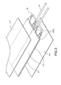
- FIG. 7 is a first schematic view of the heat-conducting component of the second embodiment according to the present invention.
- FIG. 8 is a second schematic view of the heat-conducting component of the second embodiment according to the present invention.
- FIG. 9 is a first schematic view of the heat-conducting component of the third embodiment according to the present invention.
- FIG. 10 is a second schematic view of the heat-conducting component of the third embodiment according to the present invention.
- the present invention provides an electrical heating device 1 with pluggable heating module, which includes a box body 10 and a heating module 20.
- the box body 10 includes a hollow proper 11, an upper cover plate 12, and a lower cover plate 13.
- the upper cover plate 12 covers one side of the hollow proper 11, and the lower cover plate 13 covers the other side of the hollow proper 11.
- An accommodation space 14 is formed by surrounding with the hollow proper 11, the upper cover plate 12, and the lower cover plate 13.
- One side of the hollow proper 11 is provided with a slot 111 communicating with the accommodation space 14, and the opposite side of the slot 111 of the hollow proper 11 is provided with a fixation trough 112.
- the heating module 20 is pluggable and inserted into the slot 111 of the hollow proper 11. The end away from the slot 111 of the heating module 20 is fixed inside the fixation trough 112 and separates a first chamber 141 and a second chamber 142 from the accommodation space 14.
- a waterproof gasket 30 is sandwiched between the upper cover plate 12 and the hollow proper 11, and the lower cover plate 13 and the hollow proper 11, respectively.
- the hollow proper 11, the upper cover plate 12, and the lower cover plate 13 are made of heat-resistant material, and the waterproof gasket 30 is made of silica gel or rubber.
- the heating module 20 includes a PTC heating component 21 and the heat conducting component 22.
- the heat conducting component 22 covers the outside of the PTC heating component 21.
- the PTC heating component 21 includes at least a PTC heating unit 211, a pair of electrode plates 212, and a pair of insulation heat conducting plates 213.
- Each electrode plate 212 connects both sides of the PTC heating unit 211, respectively.
- One side of each insulation heat conducting plate 213 connects each electrode plate 212, respectively, and the other side of the heat conducting plate 213 connects the inner surface of the heat conducting component 22 respectively.
- One end of each electrode plate 212 near the slot 111 of the hollow proper 11 is provided with a first electric conductive terminal 2121.
- the PTC heating unit 211 is made of ceramic material which has positive temperature coefficient.
- the heat conducting component 22 is made of aluminum or aluminum alloy, and each insulation heat conducting plate 213 is made of alumina.
- the electrical heating device and equipment 1 further includes a heat conducting glue 40, an insulation heat conducting glue 50, and a connector 60.
- Each insulation heat conducting plate 213 sticks to each electrode plate 212 by the insulation heat conducting glue 50.
- Each insulation heat conduction plate 213 sticks to the inner surface of the PTC heating component 22 by the insulation heat conducting glue 50.
- One side of the connector 60 inserted into the slot 111 and covers the outside of one end of the PTC heating component 21 near the slot 111, and electrically connects to the first electric conductive terminal 2121 of each electrode plate 212.
- the other side of the connector 60 is provided with a second electric conductive terminal 61.
- Each insulation heat conducting plate 213 and the insulation heat conducting glue 50 have the features of electrical insulation and heat conduction.
- the electrical heating device and equipment 1 further includes a liquid supply 70.
- the liquid supply 70 includes a water pump 71, a liquid inlet pipe 72, a liquid outlet pipe 73, and a liquid 74.
- the liquid inlet pipe 72 communicates with the water pump 71 and the water inlet 113 of the hollow proper 11.
- the liquid outlet pipe 73 communicates the water pump 71 and the water outlet 114 of the hollow proper 11.
- the liquid 74 is filled in the first chamber 141 and the second chamber 142 of the box body 10.
- the power source is connected to the second electric conductive terminal 61 of the connector 60 to provide the electricity to each electrode plate 212, and each electrode plate 212 can further provide the power to the PTC heating unit 211. Since the PTC heating unit 211 has large resistance value, the electricity provided by the electrode plate 212 can be converted to heat, and the heat generated by the PTC heating unit 211 can be conducted to each electrode plate 212, and further conducted from each electrode plate 212 to each insulation heat conducting plate 213. And then, the heat can be conducted from the heat conducting plate 213 to the heat conducting component 22, and the heat conducting component 22 exchanges the heat with the liquid 74 in the first chamber 141 and the second chamber 142 to achieve the goal of heating the liquid 74.
- the liquid 74 will flow into the liquid outlet pipe 73 via the water outlet 113 of the hollow proper 11, and further flows into the water pump 71 from the liquid outlet pipe 73.
- the water pump 71 inputs the liquid 74 to the liquid inlet pipe 72, and the liquid 74 can flow into the first chamber 141 and the second chamber 142 from the water inlet 113 of the hollow proper 11 via the liquid inlet pipe 72, thereby cyclically heating the liquid 74.
- the heating module 20 Since the heating module 20 is inserted into the hollow proper 11 in a pluggable way, the heating module 20 can be replaced or repaired when the heating module is damaged or not working properly, thereby saving maintenance time and the cost of replacing the electrical heating device and equipment 1.
- the heat conducting component 22 can directly heat the liquid 74, and thus improves the heating effect for the liquid 74.
- the fluid passages 1211, 1311 formed in the first chamber 141 and the second chamber 142 by each convex rib 121, 131 of the upper cover plate 12 and the lower cover plate 13, respectively the flowing distance that the liquid 74 flows into or flows out the first chamber 141 and the second chamber 142 can be increased.
- the heating module 20 has more heating time for the liquid 74, and the heating effect for heating the liquid 74 by the electrical heating device and equipment 1 can be improved as well.
- each insulation heat conducting plate 213 having the electrical insulation feature is sandwiched between the inner surface of each electrode plate 212 and the heat conducting component 22 to prevent the electrical leakage from each electrode plate 212 to the heat conducting component 22.
- the insulation heat conducting plate 213 is heat-conductive, so the heat conduction from each electrode plate 212 to the heat conducting component 22 can be improved.
- the insulation heat conducting glue 50 is made of a base material added with the high heat-conductive ceramic powder.
- the base material can be silica gel, plastic or epoxy resin
- the ceramic powder can be alumina, silicon nitride, aluminum nitride or carborundum, and thus the heat conducting effect from each electrode plate 212 to each insulation heat conducting plate 213, or from each insulation heat conducting plate 213 to the heat conducting component 22, can be even improved.
- the heat conducting glue 40 is made of electric conductive and heat conductive material.
- the heat conducting glue 40 can be made of silica gel, plastic or rubber added with copper or silver material.
- the efficiency of conducting electricity from the electrode plate 212 to the PTC heating unit 211 can be improved, thereby enhancing the effect of generating heat by the PTC heating unit 211, and improving the heat conduction from the PTC heating unit 211 to each electrode plate 212 as well.
- FIGS. 7 and 8 are the first and the second schematic view of the heat-conducting component of the second embodiment according to the present invention.
- the main difference compared to the previous embodiment is that, the heat conducting component 22 is replaced to heat conducting component 22b.
- the heat conducting component 22b includes an upper case 221 and a lower case 222.
- One surface of the upper case 221 forms a U-shaped upper standing wall 2211 constructed by three sides
- one surface of the lower case 222 forms a U-shaped lower standing wall 2221 constructed by three sides.
- Two opposite sides of the upper standing wall 2211 are formed with an upper hook 2212 bending inward
- two opposite sides of the lower standing wall 2221 are formed with a lower hook 2222 bending outward.
- Each upper case 221 and each lower case 222 buckles each other by each upper hook 2212 and each lower hook 2222.
- FIGS. 9 and 10 are the first and the second schematic view of the heat-conducting component of the third embodiment according to the present invention.
- the main difference compared to the previous embodiments is that, the heat conducting component 22 is replaced to heat conducting component 22c.
- the heat conducting component 22c includes an upper case 221, a lower case 222, and a pair of long strip objects 223.
- One surface of the upper case 221 forms a U-shaped upper standing wall 2211 constructed by three sides
- one surface of the lower case 222 forms a U-shaped lower standing wall 2221 constructed by three sides.
- the cross section of the long strip object 223 is formed H-shaped cross section which is formed with an upper track and a lower track for the upper standing wall and the lower standing wall slidably engaged therein, respectively.
Abstract
Description
- The present invention relates to an electrical heating equipment, especially to an electrical heating device with pluggable heating module.
- By the trend of energy saving and carbon emission reducing, the electric automobile will gradually replace the traditional one. The heat of the air conditioning of the traditional automobile is provided by the cooling water circulating the engine; however, the electric automobile can not be operated in the same way because the electric automobile is not driven by the engine. Therefore, an electrical heating device is developed to heat the circulating liquid for the air conditioning of the electric automobile.
- The conventional electrical heating device includes a box body and a heating module. The box body is provided with an accommodating space, and one side of the box body is provided with a water inlet and a water outlet. The heating module connects and fixes at one side of the box body, and the liquid is filled in the accommodating space. When in use, the heat generated from the heating module will be conducted to the box body, and the heat exchange will take place between the inner wall of box body and the liquid of the accommodating space, thereby achieving the goal of heating the liquid.
- However, the conventional electrical heating device has the following drawbacks. First, the heating module heats the liquid by transferring the heat to the box body, and the box body will further exchange the heat with the liquid. Since the heating process is indirectly, the heating effect is not good enough. Second, the heating module is directly fixed to one side of the box body. If the heating module is damaged or not working properly, the whole electrical heating device is always replaced since assembling/ disassembling the components of the heating module is too complicated, which results in waste of the cost.
- The present invention provides a pluggable heating module assembled with the box body, and the heating module can be replaced or repaired when the heating module is damaged or not working properly, thereby saving time for maintaining the electrical heating device.
- The present invention also utilizes a heat conducting component of the heating module directly contacting and heating the liquid of the accommodation space to improve the liquid heating effect of the electrical heating device.
- The present invention provides an electrical heating device having pluggable heating modules for heating liquid, which comprises a box body and a heating module. The box body has an accommodation space for accommodating the liquid, and the box body which is provided with a slot for communicating the accommodation space. The heating module is received in the slot in a pluggable way and separates the accommodation space into a first chamber and a second chamber. The heating module includes a positive temperature coefficient (PTC) heating component and a heat conducting component covering the outside of the PTC heating component.
- The present invention provides another electrical heating device having pluggable heating modules, which comprises a liquid supply, a box body, and a heating module. The liquid supply includes a liquid, a water pump, a liquid inlet pipe and a liquid outlet pipe connecting to the water pump. The box body has an accommodation space for accommodating the liquid, the box body is provided with a slot, a water inlet and a water outlet communicating the accommodation space. The water inlet communicates with the liquid inlet pipe, and the water outlet communicates with the liquid outlet pipe. The heating module inserting into the slot in a pluggable way and separates the accommodation space into a first chamber and a second chamber, and the water inlet and the water outlet communicate the first chamber and the second chamber, respectively. The heating module includes a PTC heating component and a heat conducting component covering the outside of the PTC heating component.
- The present invention has the advantages as follows. First, by the electric conductive feature of the heat conducting glue, the efficiency of the electricity conduction from each electrode plate to the PTC heating unit can be improved, and thus enhances the heat generating effect of the PTC heating unit. Besides, by the heat conduction feature of the heat conducting glue and the insulation heat conducting glue, the heat generated by the PTC heating unit can be conducted to the heat conducting component more efficiently, and the liquid heating effect of the electrical heating device can be better. Second, by the insulation feature of the insulation heat conducting glue and the insulation heat conducting plate, the electric leakage from each electrode plate to the heat conducting component can be prevented. Third, by utilizing the fluid passages formed in the first chamber and the second chamber by each convex rib of the upper cover plate and the lower cover plate, respectively, the flowing distance that the liquid flows into or flows out the first chamber and the second chamber can be increased. By doing so, the heating module has more heating time for the liquid, and the heating effect for heating the liquid by the electrical heating device can be improved as well.
- These and other features and advantages of the various embodiments disclosed herein will be better understood with respect to the following description and drawings, in which like numbers refer to like parts throughout, and in which:
-
FIG. 1 is an assembled perspective view of the first embodiment according to the present invention; -
FIG. 2 is an exploded perspective view of the first embodiment according to the present invention; -
FIG. 3 is an exploded perspective view of the PTC heating component of the first embodiment according to the present invention; -
FIG. 4 is a cross-sectional view of the assembled first embodiment according to the present invention; -
FIG. 5 is a schematic view of the partially magnified heating module of the first embodiment according to the present invention; -
FIG. 6 is a schematic view of the assembled first embodiment according to the present invention; -
FIG. 7 is a first schematic view of the heat-conducting component of the second embodiment according to the present invention; -
FIG. 8 is a second schematic view of the heat-conducting component of the second embodiment according to the present invention; -
FIG. 9 is a first schematic view of the heat-conducting component of the third embodiment according to the present invention; and -
FIG. 10 is a second schematic view of the heat-conducting component of the third embodiment according to the present invention. - Please refer to
FIGS. 1 to 5 . The present invention provides anelectrical heating device 1 with pluggable heating module, which includes abox body 10 and aheating module 20. - The
box body 10 includes a hollow proper 11, anupper cover plate 12, and alower cover plate 13. Theupper cover plate 12 covers one side of the hollow proper 11, and thelower cover plate 13 covers the other side of the hollow proper 11. Anaccommodation space 14 is formed by surrounding with the hollow proper 11, theupper cover plate 12, and thelower cover plate 13. One side of the hollow proper 11 is provided with aslot 111 communicating with theaccommodation space 14, and the opposite side of theslot 111 of the hollow proper 11 is provided with afixation trough 112. Theheating module 20 is pluggable and inserted into theslot 111 of the hollow proper 11. The end away from theslot 111 of theheating module 20 is fixed inside thefixation trough 112 and separates afirst chamber 141 and asecond chamber 142 from theaccommodation space 14. A side near theslot 111 of the hollow proper 11 is provided with awater inlet 113 and awater outlet 114. Thewater inlet 113 and thewater outlet 114 are connected to thefirst chamber 141 and thesecond chamber 142 respectively. A side near the hollow proper 11 of theupper cover plate 12 is formed a plurality ofconvex ribs 121 which are against an outer surface near thefirst chamber 141 of a heat conductingcomponent 22, thereby forming afluid passage 1211 in thefirst chamber 141. A side near the hollow proper 11 of thelower cover plate 13 is formed a plurality ofconvex ribs 131 which are against an outer surface near thesecond chamber 142 of the heat conductingcomponent 22, thereby forming afluid passage 1311 in thesecond chamber 142. Awaterproof gasket 30 is sandwiched between theupper cover plate 12 and the hollow proper 11, and thelower cover plate 13 and the hollow proper 11, respectively. The hollow proper 11, theupper cover plate 12, and thelower cover plate 13 are made of heat-resistant material, and thewaterproof gasket 30 is made of silica gel or rubber. - The
heating module 20 includes aPTC heating component 21 and the heat conductingcomponent 22. The heat conductingcomponent 22 covers the outside of thePTC heating component 21. ThePTC heating component 21 includes at least aPTC heating unit 211, a pair ofelectrode plates 212, and a pair of insulationheat conducting plates 213. Eachelectrode plate 212 connects both sides of thePTC heating unit 211, respectively. One side of each insulationheat conducting plate 213 connects eachelectrode plate 212, respectively, and the other side of theheat conducting plate 213 connects the inner surface of theheat conducting component 22 respectively. One end of eachelectrode plate 212 near theslot 111 of the hollow proper 11 is provided with a first electricconductive terminal 2121. ThePTC heating unit 211 is made of ceramic material which has positive temperature coefficient. Theheat conducting component 22 is made of aluminum or aluminum alloy, and each insulationheat conducting plate 213 is made of alumina. - The electrical heating device and
equipment 1 further includes aheat conducting glue 40, an insulationheat conducting glue 50, and aconnector 60. Each insulationheat conducting plate 213 sticks to eachelectrode plate 212 by the insulationheat conducting glue 50. Each insulationheat conduction plate 213 sticks to the inner surface of thePTC heating component 22 by the insulationheat conducting glue 50. One side of theconnector 60 inserted into theslot 111 and covers the outside of one end of thePTC heating component 21 near theslot 111, and electrically connects to the first electricconductive terminal 2121 of eachelectrode plate 212. The other side of theconnector 60 is provided with a second electricconductive terminal 61. Each insulationheat conducting plate 213 and the insulationheat conducting glue 50 have the features of electrical insulation and heat conduction. - Please refer to
FIG. 6 , which is a schematic view of the assembled first embodiment according to the present invention. The electrical heating device andequipment 1 further includes aliquid supply 70. Theliquid supply 70 includes awater pump 71, aliquid inlet pipe 72, aliquid outlet pipe 73, and a liquid 74. Theliquid inlet pipe 72 communicates with thewater pump 71 and thewater inlet 113 of the hollow proper 11. Theliquid outlet pipe 73 communicates thewater pump 71 and thewater outlet 114 of the hollow proper 11. The liquid 74 is filled in thefirst chamber 141 and thesecond chamber 142 of thebox body 10. - When using the electrical heating device and
equipment 1 to heat the liquid 74, the power source is connected to the second electricconductive terminal 61 of theconnector 60 to provide the electricity to eachelectrode plate 212, and eachelectrode plate 212 can further provide the power to thePTC heating unit 211. Since thePTC heating unit 211 has large resistance value, the electricity provided by theelectrode plate 212 can be converted to heat, and the heat generated by thePTC heating unit 211 can be conducted to eachelectrode plate 212, and further conducted from eachelectrode plate 212 to each insulationheat conducting plate 213. And then, the heat can be conducted from theheat conducting plate 213 to theheat conducting component 22, and theheat conducting component 22 exchanges the heat with the liquid 74 in thefirst chamber 141 and thesecond chamber 142 to achieve the goal of heating the liquid 74. Meanwhile, the liquid 74 will flow into theliquid outlet pipe 73 via thewater outlet 113 of the hollow proper 11, and further flows into thewater pump 71 from theliquid outlet pipe 73. Thewater pump 71 inputs the liquid 74 to theliquid inlet pipe 72, and the liquid 74 can flow into thefirst chamber 141 and thesecond chamber 142 from thewater inlet 113 of the hollow proper 11 via theliquid inlet pipe 72, thereby cyclically heating the liquid 74. - Since the
heating module 20 is inserted into the hollow proper 11 in a pluggable way, theheating module 20 can be replaced or repaired when the heating module is damaged or not working properly, thereby saving maintenance time and the cost of replacing the electrical heating device andequipment 1. - Besides, since the outer surface of the
heat conducting component 22 directly contacts the liquid 74 of thefirst chamber 141 and thesecond chamber 142, theheat conducting component 22 can directly heat the liquid 74, and thus improves the heating effect for the liquid 74. Moreover, by utilizing thefluid passages first chamber 141 and thesecond chamber 142 by eachconvex rib upper cover plate 12 and thelower cover plate 13, respectively, the flowing distance that the liquid 74 flows into or flows out thefirst chamber 141 and thesecond chamber 142 can be increased. By doing so, theheating module 20 has more heating time for the liquid 74, and the heating effect for heating the liquid 74 by the electrical heating device andequipment 1 can be improved as well. - Besides, each insulation
heat conducting plate 213 having the electrical insulation feature is sandwiched between the inner surface of eachelectrode plate 212 and theheat conducting component 22 to prevent the electrical leakage from eachelectrode plate 212 to theheat conducting component 22. The insulationheat conducting plate 213 is heat-conductive, so the heat conduction from eachelectrode plate 212 to theheat conducting component 22 can be improved. And also, the insulationheat conducting glue 50 is made of a base material added with the high heat-conductive ceramic powder. The base material can be silica gel, plastic or epoxy resin, and the ceramic powder can be alumina, silicon nitride, aluminum nitride or carborundum, and thus the heat conducting effect from eachelectrode plate 212 to each insulationheat conducting plate 213, or from each insulationheat conducting plate 213 to theheat conducting component 22, can be even improved. - Besides, the
heat conducting glue 40 is made of electric conductive and heat conductive material. Theheat conducting glue 40 can be made of silica gel, plastic or rubber added with copper or silver material. Thus, the efficiency of conducting electricity from theelectrode plate 212 to thePTC heating unit 211 can be improved, thereby enhancing the effect of generating heat by thePTC heating unit 211, and improving the heat conduction from thePTC heating unit 211 to eachelectrode plate 212 as well. - Please refer to
FIGS. 7 and 8 , which are the first and the second schematic view of the heat-conducting component of the second embodiment according to the present invention. The main difference compared to the previous embodiment is that, theheat conducting component 22 is replaced to heat conductingcomponent 22b. Theheat conducting component 22b includes anupper case 221 and alower case 222. One surface of theupper case 221 forms a U-shapedupper standing wall 2211 constructed by three sides, and one surface of thelower case 222 forms a U-shapedlower standing wall 2221 constructed by three sides. Two opposite sides of theupper standing wall 2211 are formed with anupper hook 2212 bending inward, and two opposite sides of thelower standing wall 2221 are formed with alower hook 2222 bending outward. Eachupper case 221 and eachlower case 222 buckles each other by eachupper hook 2212 and eachlower hook 2222. - Please refer to
FIGS. 9 and 10 , which are the first and the second schematic view of the heat-conducting component of the third embodiment according to the present invention. The main difference compared to the previous embodiments is that, theheat conducting component 22 is replaced to heat conductingcomponent 22c. Theheat conducting component 22c includes anupper case 221, alower case 222, and a pair of long strip objects 223. One surface of theupper case 221 forms a U-shapedupper standing wall 2211 constructed by three sides, and one surface of thelower case 222 forms a U-shapedlower standing wall 2221 constructed by three sides. The cross section of thelong strip object 223 is formed H-shaped cross section which is formed with an upper track and a lower track for the upper standing wall and the lower standing wall slidably engaged therein, respectively. By this arrangement, theupper case 221 can be connected with thelower case 222.
Claims (17)
- An electrical heating device (1) with pluggable heating module for heating liquid (74), comprising:a box body (10) having an accommodation space (14) for the liquid (74) contained therein, which is provided with a slot (111) communicating the accommodation space (14); anda heating module (20) received in the slot (111) in a pluggable way and separating the accommodation space (14) into a first chamber (141) and a second chamber (142), the heating module (20) including a positive temperature coefficient (PTC) heating component (21) and a heat conducting component (22) covering outside of the PTC heating component (21).
- The electrical heating device according claim 1, wherein the box body (10) includes a hollow proper (11), an upper cover plate (12) and a lower cover plate (13) covering both sides of the hollow proper (11), respectively; the accommodation space (14) is formed by surrounding with the hollow proper (11), the upper cover plate (12), and the lower cover plate (13); and the slot (111) is provided on one side of the hollow proper (11).
- The electrical heating device according claim 2, wherein a plurality of convex ribs (121, 131) against an outer surface of the heat conducting component (22) are formed on each side of the upper cover plate (12) and the lower cover plate (13) near the hollow proper (11).
- The electrical heating device according to claim 2, wherein a waterproof gasket (30) is provided between the upper cover plate (12) and the hollow proper (11), and also between the lower cover plate (13) and the hollow proper (11).
- The electrical heating device according to claim 1, further comprising an insulation heat conducting glue (50), the PTC heating component (21) being adhered to the heat conducting component (22) via the insulation heat conducting glue (50).
- The electrical heating device according to claim 5, further comprising a heat conducting glue (40), the PTC heating component (21) including at least one PTC heating unit (211), a pair of electrode plates (212) being adhered to each side of the PTC heating unit (211) via the heat conducting glue (50), and a pair of insulation heat conducting plates (213) being adhered to the pair of the electrode plates (212) via the insulation heat conducting glue (40), respectively.
- The electrical heating device according to claim 6, further comprising a connector (60) engaged on the slot (111) and covering one end of the PTC heating component (21) near the slot (111), and electrically connecting each of the pair of the electrode plates (212).
- An electrical heating equipment (1) having pluggable heating module, comprising:a liquid supply (70) including liquid (74), a pump (71), an inlet pipe (72) and an outlet pipe (73) connecting to the pump (71);a box body (10) having an accommodation space (14) for contained therein, the box body (10) provided with a slot (111), an inlet (113) and an outlet (114) communicating the accommodation space (14), the inlet (113) connecting with the inlet pipe (71), and the outlet (114) connecting with the outlet pipe (72); anda heating module (20) received in the slot (111) in a pluggable way and separating the accommodation space (14) into a first chamber (141) and a second chamber (142), the inlet (113) and the outlet (114) communicating the first chamber (141) and the second chamber (142), respectively, the heating module (20) including a positive temperature coefficient (PTC) heating component (21) and a heat conducting component (22) covering outside of the PTC heating component (21).
- The electrical heating device according to claim 8, wherein the box body (10) includes a hollow proper (11), an upper cover plate (12) and a lower cover plate (13) covering both sides of the hollow proper (11), respectively; the accommodation space (14) is formed by surrounding with the hollow proper (11), the upper cover plate (12), and the lower cover plate (13); the slot (111) is provided on one side of the hollow proper (11); and the inlet (113) and the outlet (114) are provided on another side near the slot (111) of the hollow proper (11).
- The electrical heating device according to claim 9, a plurality of convex ribs (121, 131) against an outer surface of the heat conducting component (22) are formed on each side of the upper cover plate (12) and the lower cover plate (13) near the hollow proper (11).
- The electrical heating device according to claim 9, wherein a waterproof gasket (30) is provided between the upper cover plate (12) and the hollow proper (11), and also between the lower cover plate (13) and the hollow proper (11).
- The electrical heating device according to claim 8, further comprising an insulation heat conducting glue (50), the PTC heating component (21) being adhered to the heat conducting component (22) via the insulation heat conducting glue (50).
- The electrical heating device according to claim 12, further comprising a heat conducting glue (40), the PTC heating component (21) including at least one PTC heating unit (211), a pair of electrode plates (212) being adhered to each side of the PTC heating unit (211) via the heat conducting glue (50), and a pair of insulation heat conducting plates (213) being adhered to the pair of the electrode plates (212) via the insulation heat conducting glue (40), respectively.
- The electrical heating device according to claim 13, further comprising a connector (60) engaged on the slot (111) and covering one end of the PTC heating component (21) near the slot (111), and electrically connecting each of the pair of the electrode plates (212).
- The electrical heating device according to claim 8, wherein the heat conducting component (22b, 22c) includes an upper case (221) and a lower case (222), one surface of the upper case (221) is formed a U-shaped upper standing wall (2211) constructed by three sides, one surface of the lower case (222) is formed a U-shaped lower standing wall (2221) constructed by three sides, and the upper standing wall (2211) connects the lower standing wall (2221).
- The electrical heating device according to claim 15, wherein two opposite sides of the upper standing wall (2211) are formed with an upper hook (2212) bending inward, two opposite sides of the lower standing wall (2221) are formed with a lower hook (2222) bending outward, and each upper hook (2212) and each lower hook (2222) buckles each other.
- The electrical heating device according to claim 15, wherein the heat conducting component (22c) further includes a strip object (223) having a H-shaped cross section formed with an upper track (2231) and a lower track (2231') for the upper standing wall (2211) and the lower standing wall (2221) slidably engaged therein, respectively.
Priority Applications (1)
| Application Number | Priority Date | Filing Date | Title |
|---|---|---|---|
| EP12007701.1A EP2734007B1 (en) | 2012-11-14 | 2012-11-14 | Electrical heating device and equipment with pluggable heating module |
Applications Claiming Priority (1)
| Application Number | Priority Date | Filing Date | Title |
|---|---|---|---|
| EP12007701.1A EP2734007B1 (en) | 2012-11-14 | 2012-11-14 | Electrical heating device and equipment with pluggable heating module |
Publications (2)
| Publication Number | Publication Date |
|---|---|
| EP2734007A1 true EP2734007A1 (en) | 2014-05-21 |
| EP2734007B1 EP2734007B1 (en) | 2016-09-21 |
Family
ID=47351343
Family Applications (1)
| Application Number | Title | Priority Date | Filing Date |
|---|---|---|---|
| EP12007701.1A Not-in-force EP2734007B1 (en) | 2012-11-14 | 2012-11-14 | Electrical heating device and equipment with pluggable heating module |
Country Status (1)
| Country | Link |
|---|---|
| EP (1) | EP2734007B1 (en) |
Cited By (5)
| Publication number | Priority date | Publication date | Assignee | Title |
|---|---|---|---|---|
| CN105841339A (en) * | 2016-04-25 | 2016-08-10 | 巫嘉雄 | Culvert type fluid heater |
| CN108583217A (en) * | 2018-04-24 | 2018-09-28 | 芜湖黑特新能源汽车科技有限公司 | A kind of automobile air-conditioner high-pressure heating water PTC assemblies with equipotential design |
| CN109506358A (en) * | 2017-09-14 | 2019-03-22 | 博格华纳路德维希堡有限公司 | Flow heater |
| EP3616949A1 (en) * | 2018-08-27 | 2020-03-04 | Borgwarner Emissions Systems Spain, S.L.U. | Heating device |
| CN112449446A (en) * | 2019-09-04 | 2021-03-05 | 马勒国际有限公司 | Heating element, heating assembly and motor vehicle |
Citations (4)
| Publication number | Priority date | Publication date | Assignee | Title |
|---|---|---|---|---|
| EP1872986A1 (en) * | 2006-06-28 | 2008-01-02 | Catem GmbH & Co. KG | Electrical heating device |
| WO2011016763A1 (en) * | 2009-08-04 | 2011-02-10 | Calix Ab | Electrical heating device for vehicles |
| EP2353898A1 (en) * | 2010-01-28 | 2011-08-10 | Mitsubishi Heavy Industries, Ltd. | Electric heating device and vehicle air conditioner |
| EP2388034A1 (en) * | 2010-05-04 | 2011-11-23 | WIK Far East Ltd. | Method for treating part of the human body with steam and vaporiser for applying steam to a part of the human body |
-
2012
- 2012-11-14 EP EP12007701.1A patent/EP2734007B1/en not_active Not-in-force
Patent Citations (4)
| Publication number | Priority date | Publication date | Assignee | Title |
|---|---|---|---|---|
| EP1872986A1 (en) * | 2006-06-28 | 2008-01-02 | Catem GmbH & Co. KG | Electrical heating device |
| WO2011016763A1 (en) * | 2009-08-04 | 2011-02-10 | Calix Ab | Electrical heating device for vehicles |
| EP2353898A1 (en) * | 2010-01-28 | 2011-08-10 | Mitsubishi Heavy Industries, Ltd. | Electric heating device and vehicle air conditioner |
| EP2388034A1 (en) * | 2010-05-04 | 2011-11-23 | WIK Far East Ltd. | Method for treating part of the human body with steam and vaporiser for applying steam to a part of the human body |
Cited By (10)
| Publication number | Priority date | Publication date | Assignee | Title |
|---|---|---|---|---|
| CN105841339A (en) * | 2016-04-25 | 2016-08-10 | 巫嘉雄 | Culvert type fluid heater |
| CN105841339B (en) * | 2016-04-25 | 2019-08-06 | 巫嘉雄 | Culvert formula fluid heater |
| CN109506358A (en) * | 2017-09-14 | 2019-03-22 | 博格华纳路德维希堡有限公司 | Flow heater |
| CN109506358B (en) * | 2017-09-14 | 2022-01-11 | 博格华纳路德维希堡有限公司 | Flow heater |
| CN108583217A (en) * | 2018-04-24 | 2018-09-28 | 芜湖黑特新能源汽车科技有限公司 | A kind of automobile air-conditioner high-pressure heating water PTC assemblies with equipotential design |
| EP3616949A1 (en) * | 2018-08-27 | 2020-03-04 | Borgwarner Emissions Systems Spain, S.L.U. | Heating device |
| US11571950B2 (en) | 2018-08-27 | 2023-02-07 | Borgwarner Ludwigsburg Gmbh | Heating device |
| CN112449446A (en) * | 2019-09-04 | 2021-03-05 | 马勒国际有限公司 | Heating element, heating assembly and motor vehicle |
| EP3789692A1 (en) * | 2019-09-04 | 2021-03-10 | Mahle International GmbH | Heating element, heating assembly and motor vehicle |
| CN112449446B (en) * | 2019-09-04 | 2023-04-14 | 马勒国际有限公司 | Heating element, heating assembly and motor vehicle |
Also Published As
| Publication number | Publication date |
|---|---|
| EP2734007B1 (en) | 2016-09-21 |
Similar Documents
| Publication | Publication Date | Title |
|---|---|---|
| US8934764B2 (en) | Electrical heating device and equipment with pluggable heating module | |
| EP2734007A1 (en) | Electrical heating device and equipment with pluggable heating module | |
| US10095285B2 (en) | Portable electronic device and detachable auxiliary heat-dissipating module thereof | |
| CN204534497U (en) | Light irradiation device | |
| CN110475459A (en) | The cooling means of heat-generating electronic elements and the electronic system of liquid-immersed cooling | |
| CN201655931U (en) | Heating structure, device and auxiliary module applied to batteries | |
| CN206148572U (en) | Power cell pack | |
| US20160128240A1 (en) | Cooling flow channel module for power conversion device and power conversion device including the same | |
| US20110200861A1 (en) | Heat-dissipating modlue for automobile battery | |
| CN104518255A (en) | Battery module | |
| CN210443641U (en) | Battery pack cooling system | |
| CN208092107U (en) | A kind of electric energy meter radiator | |
| CN101728596A (en) | Battery and battery pack comprising the battery | |
| KR102587588B1 (en) | Coolant heater | |
| CN212969350U (en) | High-efficient constant temperature driving motor | |
| CN201349040Y (en) | Battery set and battery pack including same | |
| CN210309967U (en) | Terminal cooling mechanism and rifle that charges | |
| CN109786885B (en) | Battery module | |
| CN206451797U (en) | A kind of silica gel heating sheet and lithium battery group for lithium battery group | |
| CN213125826U (en) | High-efficient heat dissipation type converter | |
| CN114709544A (en) | Battery package and consumer | |
| CN210224227U (en) | PTC heating liquid cooling plate of power battery | |
| CN210607541U (en) | Heating liquid cooling plate of power battery heating film | |
| CN208157467U (en) | A kind of power battery pack | |
| TWM447979U (en) | Electric heating device and apparatus for detachable heating module |
Legal Events
| Date | Code | Title | Description |
|---|---|---|---|
| PUAI | Public reference made under article 153(3) epc to a published international application that has entered the european phase |
Free format text: ORIGINAL CODE: 0009012 |
|
| 17P | Request for examination filed |
Effective date: 20131104 |
|
| AK | Designated contracting states |
Kind code of ref document: A1 Designated state(s): AL AT BE BG CH CY CZ DE DK EE ES FI FR GB GR HR HU IE IS IT LI LT LU LV MC MK MT NL NO PL PT RO RS SE SI SK SM TR |
|
| AX | Request for extension of the european patent |
Extension state: BA ME |
|
| GRAP | Despatch of communication of intention to grant a patent |
Free format text: ORIGINAL CODE: EPIDOSNIGR1 |
|
| INTG | Intention to grant announced |
Effective date: 20160429 |
|
| GRAS | Grant fee paid |
Free format text: ORIGINAL CODE: EPIDOSNIGR3 |
|
| GRAA | (expected) grant |
Free format text: ORIGINAL CODE: 0009210 |
|
| AK | Designated contracting states |
Kind code of ref document: B1 Designated state(s): AL AT BE BG CH CY CZ DE DK EE ES FI FR GB GR HR HU IE IS IT LI LT LU LV MC MK MT NL NO PL PT RO RS SE SI SK SM TR |
|
| REG | Reference to a national code |
Ref country code: GB Ref legal event code: FG4D |
|
| REG | Reference to a national code |
Ref country code: CH Ref legal event code: EP |
|
| REG | Reference to a national code |
Ref country code: AT Ref legal event code: REF Ref document number: 831947 Country of ref document: AT Kind code of ref document: T Effective date: 20161015 |
|
| REG | Reference to a national code |
Ref country code: IE Ref legal event code: FG4D |
|
| REG | Reference to a national code |
Ref country code: DE Ref legal event code: R096 Ref document number: 602012023218 Country of ref document: DE |
|
| REG | Reference to a national code |
Ref country code: FR Ref legal event code: PLFP Year of fee payment: 5 |
|
| REG | Reference to a national code |
Ref country code: LT Ref legal event code: MG4D Ref country code: NL Ref legal event code: MP Effective date: 20160921 |
|
| PG25 | Lapsed in a contracting state [announced via postgrant information from national office to epo] |
Ref country code: FI Free format text: LAPSE BECAUSE OF FAILURE TO SUBMIT A TRANSLATION OF THE DESCRIPTION OR TO PAY THE FEE WITHIN THE PRESCRIBED TIME-LIMIT Effective date: 20160921 Ref country code: RS Free format text: LAPSE BECAUSE OF FAILURE TO SUBMIT A TRANSLATION OF THE DESCRIPTION OR TO PAY THE FEE WITHIN THE PRESCRIBED TIME-LIMIT Effective date: 20160921 Ref country code: NO Free format text: LAPSE BECAUSE OF FAILURE TO SUBMIT A TRANSLATION OF THE DESCRIPTION OR TO PAY THE FEE WITHIN THE PRESCRIBED TIME-LIMIT Effective date: 20161221 Ref country code: LT Free format text: LAPSE BECAUSE OF FAILURE TO SUBMIT A TRANSLATION OF THE DESCRIPTION OR TO PAY THE FEE WITHIN THE PRESCRIBED TIME-LIMIT Effective date: 20160921 |
|
| REG | Reference to a national code |
Ref country code: AT Ref legal event code: MK05 Ref document number: 831947 Country of ref document: AT Kind code of ref document: T Effective date: 20160921 |
|
| PG25 | Lapsed in a contracting state [announced via postgrant information from national office to epo] |
Ref country code: BE Free format text: LAPSE BECAUSE OF NON-PAYMENT OF DUE FEES Effective date: 20161130 Ref country code: NL Free format text: LAPSE BECAUSE OF FAILURE TO SUBMIT A TRANSLATION OF THE DESCRIPTION OR TO PAY THE FEE WITHIN THE PRESCRIBED TIME-LIMIT Effective date: 20160921 Ref country code: GR Free format text: LAPSE BECAUSE OF FAILURE TO SUBMIT A TRANSLATION OF THE DESCRIPTION OR TO PAY THE FEE WITHIN THE PRESCRIBED TIME-LIMIT Effective date: 20161222 Ref country code: SE Free format text: LAPSE BECAUSE OF FAILURE TO SUBMIT A TRANSLATION OF THE DESCRIPTION OR TO PAY THE FEE WITHIN THE PRESCRIBED TIME-LIMIT Effective date: 20160921 Ref country code: LV Free format text: LAPSE BECAUSE OF FAILURE TO SUBMIT A TRANSLATION OF THE DESCRIPTION OR TO PAY THE FEE WITHIN THE PRESCRIBED TIME-LIMIT Effective date: 20160921 |
|
| PG25 | Lapsed in a contracting state [announced via postgrant information from national office to epo] |
Ref country code: RO Free format text: LAPSE BECAUSE OF FAILURE TO SUBMIT A TRANSLATION OF THE DESCRIPTION OR TO PAY THE FEE WITHIN THE PRESCRIBED TIME-LIMIT Effective date: 20160921 Ref country code: EE Free format text: LAPSE BECAUSE OF FAILURE TO SUBMIT A TRANSLATION OF THE DESCRIPTION OR TO PAY THE FEE WITHIN THE PRESCRIBED TIME-LIMIT Effective date: 20160921 |
|
| PG25 | Lapsed in a contracting state [announced via postgrant information from national office to epo] |
Ref country code: BE Free format text: LAPSE BECAUSE OF FAILURE TO SUBMIT A TRANSLATION OF THE DESCRIPTION OR TO PAY THE FEE WITHIN THE PRESCRIBED TIME-LIMIT Effective date: 20160921 Ref country code: SK Free format text: LAPSE BECAUSE OF FAILURE TO SUBMIT A TRANSLATION OF THE DESCRIPTION OR TO PAY THE FEE WITHIN THE PRESCRIBED TIME-LIMIT Effective date: 20160921 Ref country code: SM Free format text: LAPSE BECAUSE OF FAILURE TO SUBMIT A TRANSLATION OF THE DESCRIPTION OR TO PAY THE FEE WITHIN THE PRESCRIBED TIME-LIMIT Effective date: 20160921 Ref country code: PL Free format text: LAPSE BECAUSE OF FAILURE TO SUBMIT A TRANSLATION OF THE DESCRIPTION OR TO PAY THE FEE WITHIN THE PRESCRIBED TIME-LIMIT Effective date: 20160921 Ref country code: IS Free format text: LAPSE BECAUSE OF FAILURE TO SUBMIT A TRANSLATION OF THE DESCRIPTION OR TO PAY THE FEE WITHIN THE PRESCRIBED TIME-LIMIT Effective date: 20170121 Ref country code: BG Free format text: LAPSE BECAUSE OF FAILURE TO SUBMIT A TRANSLATION OF THE DESCRIPTION OR TO PAY THE FEE WITHIN THE PRESCRIBED TIME-LIMIT Effective date: 20161221 Ref country code: AT Free format text: LAPSE BECAUSE OF FAILURE TO SUBMIT A TRANSLATION OF THE DESCRIPTION OR TO PAY THE FEE WITHIN THE PRESCRIBED TIME-LIMIT Effective date: 20160921 Ref country code: PT Free format text: LAPSE BECAUSE OF FAILURE TO SUBMIT A TRANSLATION OF THE DESCRIPTION OR TO PAY THE FEE WITHIN THE PRESCRIBED TIME-LIMIT Effective date: 20170123 Ref country code: CZ Free format text: LAPSE BECAUSE OF FAILURE TO SUBMIT A TRANSLATION OF THE DESCRIPTION OR TO PAY THE FEE WITHIN THE PRESCRIBED TIME-LIMIT Effective date: 20160921 Ref country code: ES Free format text: LAPSE BECAUSE OF FAILURE TO SUBMIT A TRANSLATION OF THE DESCRIPTION OR TO PAY THE FEE WITHIN THE PRESCRIBED TIME-LIMIT Effective date: 20160921 |
|
| REG | Reference to a national code |
Ref country code: DE Ref legal event code: R097 Ref document number: 602012023218 Country of ref document: DE |
|
| PG25 | Lapsed in a contracting state [announced via postgrant information from national office to epo] |
Ref country code: IT Free format text: LAPSE BECAUSE OF FAILURE TO SUBMIT A TRANSLATION OF THE DESCRIPTION OR TO PAY THE FEE WITHIN THE PRESCRIBED TIME-LIMIT Effective date: 20160921 |
|
| REG | Reference to a national code |
Ref country code: CH Ref legal event code: PL |
|
| PLBE | No opposition filed within time limit |
Free format text: ORIGINAL CODE: 0009261 |
|
| STAA | Information on the status of an ep patent application or granted ep patent |
Free format text: STATUS: NO OPPOSITION FILED WITHIN TIME LIMIT |
|
| PG25 | Lapsed in a contracting state [announced via postgrant information from national office to epo] |
Ref country code: LI Free format text: LAPSE BECAUSE OF NON-PAYMENT OF DUE FEES Effective date: 20161130 Ref country code: DK Free format text: LAPSE BECAUSE OF FAILURE TO SUBMIT A TRANSLATION OF THE DESCRIPTION OR TO PAY THE FEE WITHIN THE PRESCRIBED TIME-LIMIT Effective date: 20160921 Ref country code: CH Free format text: LAPSE BECAUSE OF NON-PAYMENT OF DUE FEES Effective date: 20161130 |
|
| GBPC | Gb: european patent ceased through non-payment of renewal fee |
Effective date: 20161221 |
|
| REG | Reference to a national code |
Ref country code: IE Ref legal event code: MM4A |
|
| 26N | No opposition filed |
Effective date: 20170622 |
|
| PG25 | Lapsed in a contracting state [announced via postgrant information from national office to epo] |
Ref country code: LU Free format text: LAPSE BECAUSE OF NON-PAYMENT OF DUE FEES Effective date: 20161130 |
|
| REG | Reference to a national code |
Ref country code: FR Ref legal event code: PLFP Year of fee payment: 6 |
|
| PG25 | Lapsed in a contracting state [announced via postgrant information from national office to epo] |
Ref country code: SI Free format text: LAPSE BECAUSE OF FAILURE TO SUBMIT A TRANSLATION OF THE DESCRIPTION OR TO PAY THE FEE WITHIN THE PRESCRIBED TIME-LIMIT Effective date: 20160921 Ref country code: IE Free format text: LAPSE BECAUSE OF NON-PAYMENT OF DUE FEES Effective date: 20161114 Ref country code: GB Free format text: LAPSE BECAUSE OF NON-PAYMENT OF DUE FEES Effective date: 20161221 |
|
| PG25 | Lapsed in a contracting state [announced via postgrant information from national office to epo] |
Ref country code: CY Free format text: LAPSE BECAUSE OF FAILURE TO SUBMIT A TRANSLATION OF THE DESCRIPTION OR TO PAY THE FEE WITHIN THE PRESCRIBED TIME-LIMIT Effective date: 20160921 Ref country code: HU Free format text: LAPSE BECAUSE OF FAILURE TO SUBMIT A TRANSLATION OF THE DESCRIPTION OR TO PAY THE FEE WITHIN THE PRESCRIBED TIME-LIMIT; INVALID AB INITIO Effective date: 20121114 |
|
| PG25 | Lapsed in a contracting state [announced via postgrant information from national office to epo] |
Ref country code: HR Free format text: LAPSE BECAUSE OF FAILURE TO SUBMIT A TRANSLATION OF THE DESCRIPTION OR TO PAY THE FEE WITHIN THE PRESCRIBED TIME-LIMIT Effective date: 20160921 Ref country code: MK Free format text: LAPSE BECAUSE OF FAILURE TO SUBMIT A TRANSLATION OF THE DESCRIPTION OR TO PAY THE FEE WITHIN THE PRESCRIBED TIME-LIMIT Effective date: 20160921 Ref country code: MC Free format text: LAPSE BECAUSE OF FAILURE TO SUBMIT A TRANSLATION OF THE DESCRIPTION OR TO PAY THE FEE WITHIN THE PRESCRIBED TIME-LIMIT Effective date: 20160921 |
|
| PG25 | Lapsed in a contracting state [announced via postgrant information from national office to epo] |
Ref country code: MT Free format text: LAPSE BECAUSE OF NON-PAYMENT OF DUE FEES Effective date: 20161114 |
|
| PG25 | Lapsed in a contracting state [announced via postgrant information from national office to epo] |
Ref country code: AL Free format text: LAPSE BECAUSE OF FAILURE TO SUBMIT A TRANSLATION OF THE DESCRIPTION OR TO PAY THE FEE WITHIN THE PRESCRIBED TIME-LIMIT Effective date: 20160921 Ref country code: TR Free format text: LAPSE BECAUSE OF FAILURE TO SUBMIT A TRANSLATION OF THE DESCRIPTION OR TO PAY THE FEE WITHIN THE PRESCRIBED TIME-LIMIT Effective date: 20160921 |
|
| PGFP | Annual fee paid to national office [announced via postgrant information from national office to epo] |
Ref country code: FR Payment date: 20210903 Year of fee payment: 10 |
|
| PGFP | Annual fee paid to national office [announced via postgrant information from national office to epo] |
Ref country code: DE Payment date: 20210902 Year of fee payment: 10 |
|
| REG | Reference to a national code |
Ref country code: DE Ref legal event code: R119 Ref document number: 602012023218 Country of ref document: DE |
|
| PG25 | Lapsed in a contracting state [announced via postgrant information from national office to epo] |
Ref country code: DE Free format text: LAPSE BECAUSE OF NON-PAYMENT OF DUE FEES Effective date: 20230601 |
|
| PG25 | Lapsed in a contracting state [announced via postgrant information from national office to epo] |
Ref country code: FR Free format text: LAPSE BECAUSE OF NON-PAYMENT OF DUE FEES Effective date: 20221130 |