EP2733860A1 - Communication system - Google Patents
Communication system Download PDFInfo
- Publication number
- EP2733860A1 EP2733860A1 EP12811065.7A EP12811065A EP2733860A1 EP 2733860 A1 EP2733860 A1 EP 2733860A1 EP 12811065 A EP12811065 A EP 12811065A EP 2733860 A1 EP2733860 A1 EP 2733860A1
- Authority
- EP
- European Patent Office
- Prior art keywords
- communication
- cables
- superimposing
- cable
- separating unit
- Prior art date
- Legal status (The legal status is an assumption and is not a legal conclusion. Google has not performed a legal analysis and makes no representation as to the accuracy of the status listed.)
- Granted
Links
- 239000003990 capacitor Substances 0.000 claims abstract description 37
- 238000000926 separation method Methods 0.000 claims description 11
- 230000005674 electromagnetic induction Effects 0.000 claims description 10
- 230000008878 coupling Effects 0.000 abstract description 32
- 238000010168 coupling process Methods 0.000 abstract description 32
- 238000005859 coupling reaction Methods 0.000 abstract description 32
- 238000012790 confirmation Methods 0.000 description 2
- 238000009434 installation Methods 0.000 description 2
- 230000005856 abnormality Effects 0.000 description 1
- 230000002411 adverse Effects 0.000 description 1
- 230000009286 beneficial effect Effects 0.000 description 1
- 230000005540 biological transmission Effects 0.000 description 1
- 239000004020 conductor Substances 0.000 description 1
- 230000000694 effects Effects 0.000 description 1
- 230000001939 inductive effect Effects 0.000 description 1
- 230000010355 oscillation Effects 0.000 description 1
Images

Classifications
-
- H—ELECTRICITY
- H04—ELECTRIC COMMUNICATION TECHNIQUE
- H04B—TRANSMISSION
- H04B3/00—Line transmission systems
- H04B3/54—Systems for transmission via power distribution lines
-
- B—PERFORMING OPERATIONS; TRANSPORTING
- B60—VEHICLES IN GENERAL
- B60L—PROPULSION OF ELECTRICALLY-PROPELLED VEHICLES; SUPPLYING ELECTRIC POWER FOR AUXILIARY EQUIPMENT OF ELECTRICALLY-PROPELLED VEHICLES; ELECTRODYNAMIC BRAKE SYSTEMS FOR VEHICLES IN GENERAL; MAGNETIC SUSPENSION OR LEVITATION FOR VEHICLES; MONITORING OPERATING VARIABLES OF ELECTRICALLY-PROPELLED VEHICLES; ELECTRIC SAFETY DEVICES FOR ELECTRICALLY-PROPELLED VEHICLES
- B60L53/00—Methods of charging batteries, specially adapted for electric vehicles; Charging stations or on-board charging equipment therefor; Exchange of energy storage elements in electric vehicles
- B60L53/10—Methods of charging batteries, specially adapted for electric vehicles; Charging stations or on-board charging equipment therefor; Exchange of energy storage elements in electric vehicles characterised by the energy transfer between the charging station and the vehicle
- B60L53/14—Conductive energy transfer
- B60L53/16—Connectors, e.g. plugs or sockets, specially adapted for charging electric vehicles
-
- B—PERFORMING OPERATIONS; TRANSPORTING
- B60—VEHICLES IN GENERAL
- B60L—PROPULSION OF ELECTRICALLY-PROPELLED VEHICLES; SUPPLYING ELECTRIC POWER FOR AUXILIARY EQUIPMENT OF ELECTRICALLY-PROPELLED VEHICLES; ELECTRODYNAMIC BRAKE SYSTEMS FOR VEHICLES IN GENERAL; MAGNETIC SUSPENSION OR LEVITATION FOR VEHICLES; MONITORING OPERATING VARIABLES OF ELECTRICALLY-PROPELLED VEHICLES; ELECTRIC SAFETY DEVICES FOR ELECTRICALLY-PROPELLED VEHICLES
- B60L53/00—Methods of charging batteries, specially adapted for electric vehicles; Charging stations or on-board charging equipment therefor; Exchange of energy storage elements in electric vehicles
- B60L53/30—Constructional details of charging stations
- B60L53/34—Plug-like or socket-like devices specially adapted for contactless inductive charging of electric vehicles
-
- B—PERFORMING OPERATIONS; TRANSPORTING
- B60—VEHICLES IN GENERAL
- B60L—PROPULSION OF ELECTRICALLY-PROPELLED VEHICLES; SUPPLYING ELECTRIC POWER FOR AUXILIARY EQUIPMENT OF ELECTRICALLY-PROPELLED VEHICLES; ELECTRODYNAMIC BRAKE SYSTEMS FOR VEHICLES IN GENERAL; MAGNETIC SUSPENSION OR LEVITATION FOR VEHICLES; MONITORING OPERATING VARIABLES OF ELECTRICALLY-PROPELLED VEHICLES; ELECTRIC SAFETY DEVICES FOR ELECTRICALLY-PROPELLED VEHICLES
- B60L53/00—Methods of charging batteries, specially adapted for electric vehicles; Charging stations or on-board charging equipment therefor; Exchange of energy storage elements in electric vehicles
- B60L53/60—Monitoring or controlling charging stations
- B60L53/65—Monitoring or controlling charging stations involving identification of vehicles or their battery types
-
- B—PERFORMING OPERATIONS; TRANSPORTING
- B60—VEHICLES IN GENERAL
- B60L—PROPULSION OF ELECTRICALLY-PROPELLED VEHICLES; SUPPLYING ELECTRIC POWER FOR AUXILIARY EQUIPMENT OF ELECTRICALLY-PROPELLED VEHICLES; ELECTRODYNAMIC BRAKE SYSTEMS FOR VEHICLES IN GENERAL; MAGNETIC SUSPENSION OR LEVITATION FOR VEHICLES; MONITORING OPERATING VARIABLES OF ELECTRICALLY-PROPELLED VEHICLES; ELECTRIC SAFETY DEVICES FOR ELECTRICALLY-PROPELLED VEHICLES
- B60L58/00—Methods or circuit arrangements for monitoring or controlling batteries or fuel cells, specially adapted for electric vehicles
- B60L58/10—Methods or circuit arrangements for monitoring or controlling batteries or fuel cells, specially adapted for electric vehicles for monitoring or controlling batteries
- B60L58/12—Methods or circuit arrangements for monitoring or controlling batteries or fuel cells, specially adapted for electric vehicles for monitoring or controlling batteries responding to state of charge [SoC]
-
- H—ELECTRICITY
- H02—GENERATION; CONVERSION OR DISTRIBUTION OF ELECTRIC POWER
- H02J—CIRCUIT ARRANGEMENTS OR SYSTEMS FOR SUPPLYING OR DISTRIBUTING ELECTRIC POWER; SYSTEMS FOR STORING ELECTRIC ENERGY
- H02J7/00—Circuit arrangements for charging or depolarising batteries or for supplying loads from batteries
- H02J7/00032—Circuit arrangements for charging or depolarising batteries or for supplying loads from batteries characterised by data exchange
- H02J7/00036—Charger exchanging data with battery
-
- H—ELECTRICITY
- H02—GENERATION; CONVERSION OR DISTRIBUTION OF ELECTRIC POWER
- H02J—CIRCUIT ARRANGEMENTS OR SYSTEMS FOR SUPPLYING OR DISTRIBUTING ELECTRIC POWER; SYSTEMS FOR STORING ELECTRIC ENERGY
- H02J7/00—Circuit arrangements for charging or depolarising batteries or for supplying loads from batteries
- H02J7/00047—Circuit arrangements for charging or depolarising batteries or for supplying loads from batteries with provisions for charging different types of batteries
-
- H—ELECTRICITY
- H02—GENERATION; CONVERSION OR DISTRIBUTION OF ELECTRIC POWER
- H02J—CIRCUIT ARRANGEMENTS OR SYSTEMS FOR SUPPLYING OR DISTRIBUTING ELECTRIC POWER; SYSTEMS FOR STORING ELECTRIC ENERGY
- H02J7/00—Circuit arrangements for charging or depolarising batteries or for supplying loads from batteries
- H02J7/007—Regulation of charging or discharging current or voltage
-
- H—ELECTRICITY
- H02—GENERATION; CONVERSION OR DISTRIBUTION OF ELECTRIC POWER
- H02J—CIRCUIT ARRANGEMENTS OR SYSTEMS FOR SUPPLYING OR DISTRIBUTING ELECTRIC POWER; SYSTEMS FOR STORING ELECTRIC ENERGY
- H02J7/00—Circuit arrangements for charging or depolarising batteries or for supplying loads from batteries
- H02J7/02—Circuit arrangements for charging or depolarising batteries or for supplying loads from batteries for charging batteries from ac mains by converters
- H02J7/04—Regulation of charging current or voltage
-
- H—ELECTRICITY
- H04—ELECTRIC COMMUNICATION TECHNIQUE
- H04B—TRANSMISSION
- H04B3/00—Line transmission systems
- H04B3/54—Systems for transmission via power distribution lines
- H04B3/548—Systems for transmission via power distribution lines the power on the line being DC
-
- B—PERFORMING OPERATIONS; TRANSPORTING
- B60—VEHICLES IN GENERAL
- B60L—PROPULSION OF ELECTRICALLY-PROPELLED VEHICLES; SUPPLYING ELECTRIC POWER FOR AUXILIARY EQUIPMENT OF ELECTRICALLY-PROPELLED VEHICLES; ELECTRODYNAMIC BRAKE SYSTEMS FOR VEHICLES IN GENERAL; MAGNETIC SUSPENSION OR LEVITATION FOR VEHICLES; MONITORING OPERATING VARIABLES OF ELECTRICALLY-PROPELLED VEHICLES; ELECTRIC SAFETY DEVICES FOR ELECTRICALLY-PROPELLED VEHICLES
- B60L2210/00—Converter types
- B60L2210/30—AC to DC converters
-
- B—PERFORMING OPERATIONS; TRANSPORTING
- B60—VEHICLES IN GENERAL
- B60L—PROPULSION OF ELECTRICALLY-PROPELLED VEHICLES; SUPPLYING ELECTRIC POWER FOR AUXILIARY EQUIPMENT OF ELECTRICALLY-PROPELLED VEHICLES; ELECTRODYNAMIC BRAKE SYSTEMS FOR VEHICLES IN GENERAL; MAGNETIC SUSPENSION OR LEVITATION FOR VEHICLES; MONITORING OPERATING VARIABLES OF ELECTRICALLY-PROPELLED VEHICLES; ELECTRIC SAFETY DEVICES FOR ELECTRICALLY-PROPELLED VEHICLES
- B60L2240/00—Control parameters of input or output; Target parameters
- B60L2240/40—Drive Train control parameters
- B60L2240/52—Drive Train control parameters related to converters
- B60L2240/527—Voltage
-
- B—PERFORMING OPERATIONS; TRANSPORTING
- B60—VEHICLES IN GENERAL
- B60L—PROPULSION OF ELECTRICALLY-PROPELLED VEHICLES; SUPPLYING ELECTRIC POWER FOR AUXILIARY EQUIPMENT OF ELECTRICALLY-PROPELLED VEHICLES; ELECTRODYNAMIC BRAKE SYSTEMS FOR VEHICLES IN GENERAL; MAGNETIC SUSPENSION OR LEVITATION FOR VEHICLES; MONITORING OPERATING VARIABLES OF ELECTRICALLY-PROPELLED VEHICLES; ELECTRIC SAFETY DEVICES FOR ELECTRICALLY-PROPELLED VEHICLES
- B60L2270/00—Problem solutions or means not otherwise provided for
- B60L2270/10—Emission reduction
- B60L2270/14—Emission reduction of noise
- B60L2270/147—Emission reduction of noise electro magnetic [EMI]
-
- H—ELECTRICITY
- H04—ELECTRIC COMMUNICATION TECHNIQUE
- H04B—TRANSMISSION
- H04B2203/00—Indexing scheme relating to line transmission systems
- H04B2203/54—Aspects of powerline communications not already covered by H04B3/54 and its subgroups
- H04B2203/5404—Methods of transmitting or receiving signals via power distribution lines
- H04B2203/5416—Methods of transmitting or receiving signals via power distribution lines by adding signals to the wave form of the power source
-
- H—ELECTRICITY
- H04—ELECTRIC COMMUNICATION TECHNIQUE
- H04B—TRANSMISSION
- H04B2203/00—Indexing scheme relating to line transmission systems
- H04B2203/54—Aspects of powerline communications not already covered by H04B3/54 and its subgroups
- H04B2203/5462—Systems for power line communications
- H04B2203/547—Systems for power line communications via DC power distribution
-
- Y—GENERAL TAGGING OF NEW TECHNOLOGICAL DEVELOPMENTS; GENERAL TAGGING OF CROSS-SECTIONAL TECHNOLOGIES SPANNING OVER SEVERAL SECTIONS OF THE IPC; TECHNICAL SUBJECTS COVERED BY FORMER USPC CROSS-REFERENCE ART COLLECTIONS [XRACs] AND DIGESTS
- Y02—TECHNOLOGIES OR APPLICATIONS FOR MITIGATION OR ADAPTATION AGAINST CLIMATE CHANGE
- Y02T—CLIMATE CHANGE MITIGATION TECHNOLOGIES RELATED TO TRANSPORTATION
- Y02T10/00—Road transport of goods or passengers
- Y02T10/60—Other road transportation technologies with climate change mitigation effect
- Y02T10/70—Energy storage systems for electromobility, e.g. batteries
-
- Y—GENERAL TAGGING OF NEW TECHNOLOGICAL DEVELOPMENTS; GENERAL TAGGING OF CROSS-SECTIONAL TECHNOLOGIES SPANNING OVER SEVERAL SECTIONS OF THE IPC; TECHNICAL SUBJECTS COVERED BY FORMER USPC CROSS-REFERENCE ART COLLECTIONS [XRACs] AND DIGESTS
- Y02—TECHNOLOGIES OR APPLICATIONS FOR MITIGATION OR ADAPTATION AGAINST CLIMATE CHANGE
- Y02T—CLIMATE CHANGE MITIGATION TECHNOLOGIES RELATED TO TRANSPORTATION
- Y02T10/00—Road transport of goods or passengers
- Y02T10/60—Other road transportation technologies with climate change mitigation effect
- Y02T10/7072—Electromobility specific charging systems or methods for batteries, ultracapacitors, supercapacitors or double-layer capacitors
-
- Y—GENERAL TAGGING OF NEW TECHNOLOGICAL DEVELOPMENTS; GENERAL TAGGING OF CROSS-SECTIONAL TECHNOLOGIES SPANNING OVER SEVERAL SECTIONS OF THE IPC; TECHNICAL SUBJECTS COVERED BY FORMER USPC CROSS-REFERENCE ART COLLECTIONS [XRACs] AND DIGESTS
- Y02—TECHNOLOGIES OR APPLICATIONS FOR MITIGATION OR ADAPTATION AGAINST CLIMATE CHANGE
- Y02T—CLIMATE CHANGE MITIGATION TECHNOLOGIES RELATED TO TRANSPORTATION
- Y02T10/00—Road transport of goods or passengers
- Y02T10/60—Other road transportation technologies with climate change mitigation effect
- Y02T10/72—Electric energy management in electromobility
-
- Y—GENERAL TAGGING OF NEW TECHNOLOGICAL DEVELOPMENTS; GENERAL TAGGING OF CROSS-SECTIONAL TECHNOLOGIES SPANNING OVER SEVERAL SECTIONS OF THE IPC; TECHNICAL SUBJECTS COVERED BY FORMER USPC CROSS-REFERENCE ART COLLECTIONS [XRACs] AND DIGESTS
- Y02—TECHNOLOGIES OR APPLICATIONS FOR MITIGATION OR ADAPTATION AGAINST CLIMATE CHANGE
- Y02T—CLIMATE CHANGE MITIGATION TECHNOLOGIES RELATED TO TRANSPORTATION
- Y02T90/00—Enabling technologies or technologies with a potential or indirect contribution to GHG emissions mitigation
- Y02T90/10—Technologies relating to charging of electric vehicles
- Y02T90/12—Electric charging stations
-
- Y—GENERAL TAGGING OF NEW TECHNOLOGICAL DEVELOPMENTS; GENERAL TAGGING OF CROSS-SECTIONAL TECHNOLOGIES SPANNING OVER SEVERAL SECTIONS OF THE IPC; TECHNICAL SUBJECTS COVERED BY FORMER USPC CROSS-REFERENCE ART COLLECTIONS [XRACs] AND DIGESTS
- Y02—TECHNOLOGIES OR APPLICATIONS FOR MITIGATION OR ADAPTATION AGAINST CLIMATE CHANGE
- Y02T—CLIMATE CHANGE MITIGATION TECHNOLOGIES RELATED TO TRANSPORTATION
- Y02T90/00—Enabling technologies or technologies with a potential or indirect contribution to GHG emissions mitigation
- Y02T90/10—Technologies relating to charging of electric vehicles
- Y02T90/14—Plug-in electric vehicles
-
- Y—GENERAL TAGGING OF NEW TECHNOLOGICAL DEVELOPMENTS; GENERAL TAGGING OF CROSS-SECTIONAL TECHNOLOGIES SPANNING OVER SEVERAL SECTIONS OF THE IPC; TECHNICAL SUBJECTS COVERED BY FORMER USPC CROSS-REFERENCE ART COLLECTIONS [XRACs] AND DIGESTS
- Y02—TECHNOLOGIES OR APPLICATIONS FOR MITIGATION OR ADAPTATION AGAINST CLIMATE CHANGE
- Y02T—CLIMATE CHANGE MITIGATION TECHNOLOGIES RELATED TO TRANSPORTATION
- Y02T90/00—Enabling technologies or technologies with a potential or indirect contribution to GHG emissions mitigation
- Y02T90/10—Technologies relating to charging of electric vehicles
- Y02T90/16—Information or communication technologies improving the operation of electric vehicles
- Y02T90/167—Systems integrating technologies related to power network operation and communication or information technologies for supporting the interoperability of electric or hybrid vehicles, i.e. smartgrids as interface for battery charging of electric vehicles [EV] or hybrid vehicles [HEV]
-
- Y—GENERAL TAGGING OF NEW TECHNOLOGICAL DEVELOPMENTS; GENERAL TAGGING OF CROSS-SECTIONAL TECHNOLOGIES SPANNING OVER SEVERAL SECTIONS OF THE IPC; TECHNICAL SUBJECTS COVERED BY FORMER USPC CROSS-REFERENCE ART COLLECTIONS [XRACs] AND DIGESTS
- Y04—INFORMATION OR COMMUNICATION TECHNOLOGIES HAVING AN IMPACT ON OTHER TECHNOLOGY AREAS
- Y04S—SYSTEMS INTEGRATING TECHNOLOGIES RELATED TO POWER NETWORK OPERATION, COMMUNICATION OR INFORMATION TECHNOLOGIES FOR IMPROVING THE ELECTRICAL POWER GENERATION, TRANSMISSION, DISTRIBUTION, MANAGEMENT OR USAGE, i.e. SMART GRIDS
- Y04S30/00—Systems supporting specific end-user applications in the sector of transportation
- Y04S30/10—Systems supporting the interoperability of electric or hybrid vehicles
- Y04S30/14—Details associated with the interoperability, e.g. vehicle recognition, authentication, identification or billing
Definitions
- the present invention relates to a communication system in which a power feeding device and a power receiving device are connected with each other through a cable, and communication of control signals necessary for charge control based on power feeding from the power feeding device to the power receiving device is performed through the cable.
- a hybrid vehicle includes a plug-in hybrid vehicle which can also be charged from an external power feeding device to a battery.
- a plug of a charge cable connected to an external power feeding device is connected to a connector device at a feeding port provided at the vehicle and power is fed through a charge cable from the power feeding device to the battery of the vehicle so as to charge the battery.
- a charge control system in which a control cable transmitting and receiving a control pilot signal to/from the power feeding device and the vehicle, and charge control is performed based on the control pilot signal (see Patent Document 1, for example).
- a communication system has thus been noted in which communication signals including information used for management and the like are superimposed onto control pilot signals communicated through a control cable.
- an electromagnetic inductive signal transformer (a circuit element such as a coupling transformer) which superimposes or separates signals onto or from a control cable is connected to a branch line from each control cable.
- the control cable needs to be branched, and thus an extra space is required for placing a branched portion of the cable and the branched lines. Since a number of electronic devices are mounted on a vehicle such as an electric vehicle, there is only a limited space in the vehicle for placing various devices. With the configuration of the communication system described above, therefore, it is not easy to secure a space for placing the branched portion and branched lines of the control cable. Reduction in size and space is thus required for the devices necessary for the communication.
- a charging station installed outside a vehicle or a power feeding device installed in a rather spacy area is less limited in its installation space compared to the case with devices in a vehicle.
- various devices instead of considering reduction in size or space thereof, devices which have proven to be successful in the past may preferably be employed.
- devices with widely-adopted configurations may preferably be employed in light of compatibility.
- An object of the invention is to provide a communication system for realizing communication in the case where a control signal such as a control pilot signal is superimposed by a signal different from the control signal, even when wiring with a configuration setting a high value on actual performance and compatibility is coexistent with wiring with another configuration setting a high value on reduction in size and space.
- a communication system in which a power feeding device is connected to a vehicle on which an electric storage device receiving power from the power feeding device through two cables, and communication of a control signal required for charge control of the electric storage device is performed through the cables, is characterized in that one of the power feeding device and the vehicle includes a first superimposing/separating unit connected to two branch lines branched from the two cables, respectively, and performing superimposition of a communication signal different from the control signal onto communication through the cables and performing separation of the communication signal superimposed onto the communication through the cables, and a first communication unit transmitting and receiving a communication signal through the first superimposing/separating unit, and that another one of the power feeding device and the vehicle includes a second superimposing/separating unit located in one of the cables and performing superimposition of the communication signal onto communication through the cable and performing separation of the communication signal superimposed onto the communication through the cable, and a second communication unit transmitting and receiving a communication signal through the second superimposing/separating unit.
- the communication system is characterized in that the first superimposing/separating unit includes a capacitor connected to each of the two branch lines, a first signal transformer of an electromagnetic induction type in which a primary coil is connected to the capacitor and a secondary coil is connected to the first communication unit, and that the second superimposing/separating unit includes a second signal transformer of an electromagnetic induction type in which a primary coil is interposed in said one of the cables and a secondary coil is connected to the second communication unit, and a capacitor connected between the two cables.
- the communication system according to the present invention is characterized in that one of the cables is grounded.
- a communication system in which a power feeding device is connected to a power receiving device by two cables, and communication of a control signal required for charge control based on power fed from the power feeding device to the power receiving device is performed through the cables, is characterized in that one of the power feeding device and the power receiving device includes a first superimposing/separating unit connected to two branch lines branched from the two cables, respectively, and performing superimposition of a communication signal different from the control signal onto communication through the cables and separation of the communication signal superimposed onto the communication through the cables, and a first communication unit transmitting and receiving a communication signal through the first superimposing/separating unit, and that another one of the power feeding device and the power receiving device includes a second superimposing/separating unit located in one of the cables and performing superimposition of the communication signal onto communication through the cable and separation of the communication signal superimposed onto the communication through the cable, and a second communication unit transmitting and receiving a communication signal through the second superimposing/separating unit.
- one of the devices connected through cables is provided with the first superimposing/separating unit having a signal transformer of an electromagnetic induction type such as a coupling transformer at two branch lines branched from two cables, while another one of the devices is provided with the second superimposing/separating unit having a signal transformer of an electromagnetic induction type at one of the cables.
- a closed loop circuit including, continuously, one cable, one branch line, a capacitor for a device on one side, a primary coil for a device on one side, a capacitor for a device on one side, another branch line, another cable, a primary coil for a device on another side, a capacitor for a device on another side and one cable, ... continued from one to another. This allows communication through a control pilot line and a GND line to be performed.
- a resistance value and a turn ratio of a coil may be so set as to satisfy a predetermined condition, allowing both devices to perform communication in the substantially same communication band, and thereby preventing communication from being adversely affected due to abnormality caused by noise getting mixed in.
- the present invention is applied to a communication system in which, when power is fed from a power feeding device, two cables for transmitting a control signal such as a control pilot signal required for charge control are used to transmit a communication signal different from a control signal.
- a control signal such as a control pilot signal required for charge control
- One of the device on the power feeding side and the device on the power receiving side is provided with the first superimposing/separating unit connected to two branch lines branched from the two cables, respectively, and performing superimposition and separation of communication signals
- another one of the devices is provided with the second superimposing/separating unit located in one of the cables and performing superimposition and separation of communication signals.
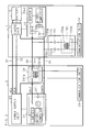
- Fig. 1 is an explanatory view illustrating a configuration example of a communication system according to Embodiment 1 of the present invention.
- Embodiment 1 describes an example where the invention is applied to feed control in feeding power from a charging station 2 serving as a feeding device to a battery (electric storage device) 10 included in an electric vehicle 1.
- the electric vehicle 1 and the charging station 2 are connected with each other by two charge cables 31 and 32 used as power supply lines, a control cable 33 for transmitting a control signal required for charge control, and a ground cable 34.
- These various cables form a circuitry illustrated in Fig. 1 when coupling a plug located at the end of the cable on the charging station 2 side with a connection port located on the electric vehicle side.
- the charge cables 31 and 32 are AC lines to which alternate current voltage is applied.
- the control cable 33 is a signal line for transmitting and receiving control signals such as control pilot signals, and charge control is performed based on the control pilot signals that are sent and received.
- two cables of the control cable 33 and the ground cable 34 are used to transmit information for management such as the charge management and accounting management as well as other various kinds of information, as communication signals different from the control signals.
- the communication system of the present invention is to superimpose a communication signal onto a control signal (control pilot signal) to be transmitted through two cables of the control cable 33 and ground cable 34 and to perform communication.
- the charging station 2 includes a power supply unit 20 supplying alternate current (hereinafter also referred to as AC) power, a charge control unit 21 performing communication concerning charge control, a superimposing/separating unit 22 superimposing and separating communication signals, and a communication unit 23 transmitting and receiving communication signals.
- the power supply unit 20 is connected to one end of each of the charge cables 31 and 32, and to the ground cable 34.
- the charge control unit 21 is connected to one end of the control cable 33 and to the ground cable 34. While the control cable 33 and ground cable 34 correspond to internal wiring serving as extension cables for each of the cables in the charging station 2, the portions of the extended cables disposed as internal wiring will be described as the control cable 33 and ground cable 34 in the description below.
- Each of the control cable 33 and ground cable 34 is connected to one end of each of branch lines 33a and 34a that are branched between the charge control unit 21 and the plug.
- the other end of each of the branch lines 33a and 34a is connected to the superimposing/separating unit 22.
- the charge control unit 21 includes various elements such as a capacitor 211 connecting the control cable 33 with the ground cable 34, as well as various circuits such as a rectangular-wave oscillation circuit, a microcomputer and a buffer.
- the charge control unit 21 is a circuit on the output side conforming to the international standard concerning charge control, which performs charge control in different states such as the connection confirmation or the start of energizing by transmitting and receiving control signals such as control pilot signals.
- the superimposing/separating unit 22 includes capacitors 221 and 222 as well as a coupling transformer (signal transformer of an electromagnetic induction type) 223.
- a terminal on one end of each of the capacitors 221 and 222 is connected to the other end of each of the branch lines 33a and 34a.
- a terminal on the other end of each of the capacitors 221 and 222 is connected to a primary coil 223a of the coupling transformer 223.
- the branch line 33a, capacitor 221, primary coil 223a of coupling transformer 223, capacitor 222 and branch line 34a are connected in series between the control cable 33 and the ground cable 34 in this order.
- a secondary coil 223b of the coupling transformer 223 is then connected to the communication unit 23.
- the superimposing/separating unit 22 superimposes a communication signal or separates the superimposed communication signal onto/from the communication of a control signal through two cables of the control cable 33 and ground cable 34. Accordingly, the superimposing/separating unit 22 superimposes various kinds of communication signals output from the communication unit 23 or inputs the separated various kinds of communication signals to the communication unit 23, to implement communication in the communication unit 23.
- the electric vehicle 1 includes, in addition to the battery 10, a charge unit 11 for charging the battery 10, a charge control unit 12 performing communication concerning charge control, a superimposing/separating unit 13 performing superimposition and separation for communication signals, and a communication unit 14 transmitting and receiving communication signals.
- the electric vehicle 1 is connected to the other end of each of the charge cables 31 and 32, the other end of the control cable 33 and the ground cable 34.
- the other end of each of the charge cables 31 and 32 is connected to the charge unit 11 through the AC lines disposed inside the electric vehicle 1, and the battery 10 is charged by the charge unit 11.
- the other end of the control cable 33 is connected to the charge control unit 12 through an extension cable disposed as internal wiring in the electric vehicle 1.
- the ground cable 34 is connected to the charge unit 11, battery 10 and charge control unit 12.
- the extended cables disposed as internal wiring are also included in the control cable 33 and ground cable 34 for the sake of convenience.
- the charge control unit 12 includes various elements such as a capacitor 121 connecting the control cable 33 with the ground cable 34, and various circuits such as a microcomputer and a buffer.
- the charge control unit 12 is a circuit on the input side conforming to the international standard concerning charge control, which performs charge control in different states such as the connection confirmation or the start of energizing by transmitting and receiving control signals such as control pilot signals.
- a superimposing/separating unit 13 is disposed on the control cable 33.
- the superimposing/separating unit 13 includes a coupling transformer (signal transformer of electromagnetic induction type) 131, in which a primary coil 131a of the coupling transformer is interposed in the control cable 33.
- a secondary coil 131b of the coupling transformer 131 is connected to the communication unit 14.
- the superimposing/separating unit 13 superimposes a communication signal and separates the superimposed communication signal onto/from the communication of a control signal. Accordingly, the superimposing/separating unit 13 superimposes various kinds of communication signals output from the communication unit 14 and inputs the separated various kinds of communication signals to the communication unit 14, to implement communication in the communication unit 14.
- the charging station 2 and electric vehicle 1 are connected with each other by the charge cables 31, 32, control cable 33 and ground cable 34, so that the energization path by the charge cables 31 and 32 as well as the transmission path for control signals by the control cable 33 are secured and also grounding is ensured.
- the control cable 33, ground cable 34, branch lines 33a, 34a, capacitors 221, 222, primary coil 223a of coupling transformer 223, capacitor 121 of charge control unit 12, and primary coil 131a of coupling transformer 131 form a closed current loop circuit.
- the coupling transformers 223 and 131 arranged in the loop allows communication signals to be superimposed and separated, which enables communication to be performed between the charging station 2 and electric vehicles.
- the communication unit 23 in the charging station 2 performs communication using the superimposing/separating unit 22 with a configuration in which the branch lines 33a and 34a branched from the control cable 33 and ground cable 34 are connected to the capacitors 221, 222 and coupling transistor 223, while the communication unit 14 in the electric vehicle 1 performs communication using superimposing/separating unit 13 with a configuration in which the coupling transformer 131 is installed in the control cable 33 and the capacitor 121 is connected between the control cable 33 and ground cable 34, which allows the charging station 2 and electric vehicle 1 to have differently-configured communication devices mounted thereto.
- control cable 33, ground cable 34, branch lines 33a, 34a, capacitors 221, 222, primary coil 223a of coupling transformer 223, capacitor 121, and primary coil 131a of coupling transformer 131 form a closed current loop circuit. This enables communication to be performed between the charging station 2 and the electric vehicle 1.
- a device concerning communication mounted to the electric vehicle 1 does not need to have the control cable 33 and ground cable 34 branched, and therefore does not need to reserve a space for installation of branch parts or branch lines in the electric vehicle 1. It is thus possible to realize reduction in size and space, compared to the device concerning communication in the charging station 2.
- Embodiment 2 shows a configuration in which, in Embodiment 1, a device concerning communication is disposed by installing branch parts and branch lines for a control cable and a ground cable on the electric vehicle side, while a superimposing/separating unit is provided in a control cable on the charging station side.
- configuration parts similar to those in Embodiment 1 are denoted by similar reference codes, for which reference may be made to Embodiment 1, and will not be described in detail here.
- Fig. 2 is an explanatory view illustrating a configuration example of a communication system according to Embodiment 2.
- a charge control unit 21 included in a charging station 2 is connected to a control cable 33 and a ground cable 34.
- a superimposing/separating unit 24 is disposed on the control cable 33 in the electric vehicle 1.
- the superimposing/separating unit 24 is provided with a coupling transformer (signal transformer of an electromagnetic induction type) 241, in which a primary coil 241a of the coupling transformer 241 is interposed in the control cable 33.
- a secondary coil 241b of the coupling transformer 241 is connected to the communication unit 23.
- the superimposing/separating unit 24 superimposes communication signals and separates the superimposed communication signals onto/from the communication of control signals. Accordingly, the superimposing/separating unit 24 superimposes various kinds of communication signals output from the communication unit 23 and inputs the separated various kinds of communication signals to the communication unit 23, to perform communication in the communication unit 23.
- the charge control unit 12 included in the electric vehicle 1 is connected to the control cable 33 and ground cable 34.
- Each of the control cable 33 and ground cable 34 in the electric vehicle 1 is connected to one end of each of branch lines 33b and 34b branched in an area between the charge control unit 12 and a connection port.
- the other end of each of the branch lines 33b and 34b is connected to a superimposing/separating unit 15.
- the superimposing/separating unit 15 includes capacitors 151, 152 and a coupling transformer (signal transformer of an electromagnetic induction type) 153.
- the other ends of the respective branch lines 33b and 34b are connected with terminals on one-end sides of the capacitors 151 and 152.
- the terminal on the other end side of each of the capacitors 151 and 152 is connected to a primary coil 153a of the coupling transformer 153.
- the branch line 33b, capacitor 151, primary coil 153a of coupling transformer 153, capacitor 152 and branch line 34b are connected in series between the control cable 33 and the ground cable 34 in this order.
- the secondary coil 153b of the coupling transformer 153 is then connected to the communication unit 14.
- the superimposing/separating unit 15 superimposes communication signals and separates the superimposed communication signals onto/from the communication of control signals through two cables of the control cable 33 and the ground cable 34. Accordingly, the superimposing/separating unit 15 superimposes various kinds of communication signals output from the communication unit 14 and inputs the separated various kinds of communication signals to the communication unit 14, to perform communication in the communication unit 14.
- Such a configuration allows a closed current loop circuit to be formed and communication to be performed between the charging station 2 and the electric vehicle 1 in communication in any directions, as in the case with Embodiment 1.
- Embodiments 1 and 2 described an example in which an electric vehicle is employed as a vehicle having a communication function
- the present invention is not limited thereto, but may employ another vehicle having a function of being charged to its battery from an external source, such as a plug-in hybrid vehicle.
- a charging station is employed as a power feeding device having a communication function
- the present invention is not limited thereto, but may employ another device having a function of feeding power to a vehicle through a control cable.
- charge control is performed by a control cable in the case where a user connects a charge cable to an electric outlet installed at his/her house to charge a vehicle
- a device concerning communication may be installed on a switchboard in the house.
- a circuit in which power line communication is performed may be mounted in a control cable.
- a cable other than a ground cable may be used as a cable to be combined with a control cable.
- a control cable and a ground cable are used as communication paths for control signals or communication signals, a conductor such as a vehicle body or a housing of a power feeding device may be used for one or both of the above.
- the configuration of the power control system according to the present invention may be applied not only to in-band communication but also to other various communication systems performing in-band communication (system in which a personal computer, a mobile terminal electronic device and AV devices perform power line communication at home or in office, for example).
Abstract
Description
- The present invention relates to a communication system in which a power feeding device and a power receiving device are connected with each other through a cable, and communication of control signals necessary for charge control based on power feeding from the power feeding device to the power receiving device is performed through the cable.
- In recent years, electric and hybrid vehicles have become widespread, which are provided with devices such as a motor, a battery and the like, and which run by the motor driven by power stored in the battery. An electric vehicle needs to be charged from an external power feeding device to a battery. A hybrid vehicle includes a plug-in hybrid vehicle which can also be charged from an external power feeding device to a battery. In a vehicle charged from the outside to its battery, a plug of a charge cable connected to an external power feeding device is connected to a connector device at a feeding port provided at the vehicle and power is fed through a charge cable from the power feeding device to the battery of the vehicle so as to charge the battery.
- Moreover, in charging from a feeding device to a vehicle, a charge control system may be employed in which a control cable transmitting and receiving a control pilot signal to/from the power feeding device and the vehicle, and charge control is performed based on the control pilot signal (see Patent Document 1, for example).
- Furthermore, as power feeding from a power feeding device has widely been commercialized, it has been required to employ communication function of transmitting and receiving information for management of charge amount management, accounting management and the like between a vehicle and a power feeding device.
- A communication system has thus been noted in which communication signals including information used for management and the like are superimposed onto control pilot signals communicated through a control cable. In this communication system, such a configuration is employed that an electromagnetic inductive signal transformer (a circuit element such as a coupling transformer) which superimposes or separates signals onto or from a control cable is connected to a branch line from each control cable.
-
- Patent Document 1: Japanese Patent Application Laid-Open No.
2009-106053 - In the communication system described above, however, the control cable needs to be branched, and thus an extra space is required for placing a branched portion of the cable and the branched lines. Since a number of electronic devices are mounted on a vehicle such as an electric vehicle, there is only a limited space in the vehicle for placing various devices. With the configuration of the communication system described above, therefore, it is not easy to secure a space for placing the branched portion and branched lines of the control cable. Reduction in size and space is thus required for the devices necessary for the communication.
- Meanwhile, a charging station installed outside a vehicle or a power feeding device installed in a rather spacy area, for example, near a parking space at a car-owner's house, is less limited in its installation space compared to the case with devices in a vehicle. For built-in various devices, instead of considering reduction in size or space thereof, devices which have proven to be successful in the past may preferably be employed. Furthermore, in facilities such as a charging station where different vehicles stop by, devices with widely-adopted configurations may preferably be employed in light of compatibility.
- The present invention has been made in view of the above circumstances. An object of the invention is to provide a communication system for realizing communication in the case where a control signal such as a control pilot signal is superimposed by a signal different from the control signal, even when wiring with a configuration setting a high value on actual performance and compatibility is coexistent with wiring with another configuration setting a high value on reduction in size and space.
- A communication system according to the present invention, in which a power feeding device is connected to a vehicle on which an electric storage device receiving power from the power feeding device through two cables, and communication of a control signal required for charge control of the electric storage device is performed through the cables, is characterized in that one of the power feeding device and the vehicle includes a first superimposing/separating unit connected to two branch lines branched from the two cables, respectively, and performing superimposition of a communication signal different from the control signal onto communication through the cables and performing separation of the communication signal superimposed onto the communication through the cables, and a first communication unit transmitting and receiving a communication signal through the first superimposing/separating unit, and that another one of the power feeding device and the vehicle includes a second superimposing/separating unit located in one of the cables and performing superimposition of the communication signal onto communication through the cable and performing separation of the communication signal superimposed onto the communication through the cable, and a second communication unit transmitting and receiving a communication signal through the second superimposing/separating unit.
- The communication system according to the present invention is characterized in that the first superimposing/separating unit includes a capacitor connected to each of the two branch lines, a first signal transformer of an electromagnetic induction type in which a primary coil is connected to the capacitor and a secondary coil is connected to the first communication unit, and that the second superimposing/separating unit includes a second signal transformer of an electromagnetic induction type in which a primary coil is interposed in said one of the cables and a secondary coil is connected to the second communication unit, and a capacitor connected between the two cables.
- The communication system according to the present invention is characterized in that one of the cables is grounded.
- A communication system according to the present invention, in which a power feeding device is connected to a power receiving device by two cables, and communication of a control signal required for charge control based on power fed from the power feeding device to the power receiving device is performed through the cables, is characterized in that one of the power feeding device and the power receiving device includes a first superimposing/separating unit connected to two branch lines branched from the two cables, respectively, and performing superimposition of a communication signal different from the control signal onto communication through the cables and separation of the communication signal superimposed onto the communication through the cables, and a first communication unit transmitting and receiving a communication signal through the first superimposing/separating unit, and that another one of the power feeding device and the power receiving device includes a second superimposing/separating unit located in one of the cables and performing superimposition of the communication signal onto communication through the cable and separation of the communication signal superimposed onto the communication through the cable, and a second communication unit transmitting and receiving a communication signal through the second superimposing/separating unit.
- In the present invention, one of the devices connected through cables is provided with the first superimposing/separating unit having a signal transformer of an electromagnetic induction type such as a coupling transformer at two branch lines branched from two cables, while another one of the devices is provided with the second superimposing/separating unit having a signal transformer of an electromagnetic induction type at one of the cables. By thus making the configuration concerning wiring for the device on one side different from that for the device on another side, actual performance and compatibility may be emphasized on one side while reduction in size and space may be achieved on another side.
- Moreover, in the present invention, a closed loop circuit including, continuously, one cable, one branch line, a capacitor for a device on one side, a primary coil for a device on one side, a capacitor for a device on one side, another branch line, another cable, a primary coil for a device on another side, a capacitor for a device on another side and one cable, ... continued from one to another. This allows communication through a control pilot line and a GND line to be performed.
- Furthermore, in the present invention, a resistance value and a turn ratio of a coil may be so set as to satisfy a predetermined condition, allowing both devices to perform communication in the substantially same communication band, and thereby preventing communication from being adversely affected due to abnormality caused by noise getting mixed in.
- The present invention is applied to a communication system in which, when power is fed from a power feeding device, two cables for transmitting a control signal such as a control pilot signal required for charge control are used to transmit a communication signal different from a control signal. One of the device on the power feeding side and the device on the power receiving side is provided with the first superimposing/separating unit connected to two branch lines branched from the two cables, respectively, and performing superimposition and separation of communication signals, whereas another one of the devices is provided with the second superimposing/separating unit located in one of the cables and performing superimposition and separation of communication signals. Such a configuration allows the device on one side to emphasize actual performance and compatibility, and the device on another side to reduce the size and space, presenting beneficial effects. It is therefore possible to have such a configuration that a power feeding device such as a public charging station which has abundant space but needs to have compatibility is provided with the first superimposing/separating unit, while a vehicle for which reduction in size and space is desired is provided with the second superimposing/separating unit.
-
-
Fig. 1 is an explanatory view illustrating a configuration example of a communication system according to Embodiment 1; and -
Fig. 2 is an explanatory view illustrating a configuration example of a communication system according to Embodiment 2. - The present invention will specifically be described below with reference to the drawings illustrating the embodiments thereof.
-
Fig. 1 is an explanatory view illustrating a configuration example of a communication system according to Embodiment 1 of the present invention. Embodiment 1 describes an example where the invention is applied to feed control in feeding power from a charging station 2 serving as a feeding device to a battery (electric storage device) 10 included in an electric vehicle 1. The electric vehicle 1 and the charging station 2 are connected with each other by twocharge cables control cable 33 for transmitting a control signal required for charge control, and aground cable 34. These various cables form a circuitry illustrated inFig. 1 when coupling a plug located at the end of the cable on the charging station 2 side with a connection port located on the electric vehicle side. - The
charge cables control cable 33 is a signal line for transmitting and receiving control signals such as control pilot signals, and charge control is performed based on the control pilot signals that are sent and received. Furthermore, in the communication system according to the present invention, two cables of thecontrol cable 33 and theground cable 34 are used to transmit information for management such as the charge management and accounting management as well as other various kinds of information, as communication signals different from the control signals. In other words, the communication system of the present invention is to superimpose a communication signal onto a control signal (control pilot signal) to be transmitted through two cables of thecontrol cable 33 andground cable 34 and to perform communication. - The charging station 2 includes a
power supply unit 20 supplying alternate current (hereinafter also referred to as AC) power, acharge control unit 21 performing communication concerning charge control, a superimposing/separatingunit 22 superimposing and separating communication signals, and acommunication unit 23 transmitting and receiving communication signals. Thepower supply unit 20 is connected to one end of each of thecharge cables ground cable 34. Thecharge control unit 21 is connected to one end of thecontrol cable 33 and to theground cable 34. While thecontrol cable 33 andground cable 34 correspond to internal wiring serving as extension cables for each of the cables in the charging station 2, the portions of the extended cables disposed as internal wiring will be described as thecontrol cable 33 andground cable 34 in the description below. - Each of the
control cable 33 andground cable 34 is connected to one end of each of branch lines 33a and 34a that are branched between thecharge control unit 21 and the plug. The other end of each of the branch lines 33a and 34a is connected to the superimposing/separatingunit 22. - The
charge control unit 21 includes various elements such as acapacitor 211 connecting thecontrol cable 33 with theground cable 34, as well as various circuits such as a rectangular-wave oscillation circuit, a microcomputer and a buffer. Thecharge control unit 21 is a circuit on the output side conforming to the international standard concerning charge control, which performs charge control in different states such as the connection confirmation or the start of energizing by transmitting and receiving control signals such as control pilot signals. - The superimposing/separating
unit 22 includescapacitors separating unit 22, a terminal on one end of each of thecapacitors capacitors coupling transformer 223. In other words, the branch line 33a,capacitor 221, primary coil 223a ofcoupling transformer 223,capacitor 222 and branch line 34a are connected in series between thecontrol cable 33 and theground cable 34 in this order. Asecondary coil 223b of thecoupling transformer 223 is then connected to thecommunication unit 23. - The superimposing/separating
unit 22 superimposes a communication signal or separates the superimposed communication signal onto/from the communication of a control signal through two cables of thecontrol cable 33 andground cable 34. Accordingly, the superimposing/separatingunit 22 superimposes various kinds of communication signals output from thecommunication unit 23 or inputs the separated various kinds of communication signals to thecommunication unit 23, to implement communication in thecommunication unit 23. - The electric vehicle 1 includes, in addition to the
battery 10, acharge unit 11 for charging thebattery 10, acharge control unit 12 performing communication concerning charge control, a superimposing/separatingunit 13 performing superimposition and separation for communication signals, and acommunication unit 14 transmitting and receiving communication signals. - The electric vehicle 1 is connected to the other end of each of the
charge cables control cable 33 and theground cable 34. The other end of each of thecharge cables charge unit 11 through the AC lines disposed inside the electric vehicle 1, and thebattery 10 is charged by thecharge unit 11. The other end of thecontrol cable 33 is connected to thecharge control unit 12 through an extension cable disposed as internal wiring in the electric vehicle 1. Moreover, theground cable 34 is connected to thecharge unit 11,battery 10 andcharge control unit 12. In the description below, the extended cables disposed as internal wiring are also included in thecontrol cable 33 andground cable 34 for the sake of convenience. - The
charge control unit 12 includes various elements such as acapacitor 121 connecting thecontrol cable 33 with theground cable 34, and various circuits such as a microcomputer and a buffer. Thecharge control unit 12 is a circuit on the input side conforming to the international standard concerning charge control, which performs charge control in different states such as the connection confirmation or the start of energizing by transmitting and receiving control signals such as control pilot signals. - In the electric vehicle 1, a superimposing/separating
unit 13 is disposed on thecontrol cable 33. The superimposing/separatingunit 13 includes a coupling transformer (signal transformer of electromagnetic induction type) 131, in which a primary coil 131a of the coupling transformer is interposed in thecontrol cable 33. Asecondary coil 131b of thecoupling transformer 131 is connected to thecommunication unit 14. - The superimposing/separating
unit 13 superimposes a communication signal and separates the superimposed communication signal onto/from the communication of a control signal. Accordingly, the superimposing/separatingunit 13 superimposes various kinds of communication signals output from thecommunication unit 14 and inputs the separated various kinds of communication signals to thecommunication unit 14, to implement communication in thecommunication unit 14. - The charging station 2 and electric vehicle 1 are connected with each other by the
charge cables control cable 33 andground cable 34, so that the energization path by thecharge cables control cable 33 are secured and also grounding is ensured. In the state where the charging station 2 and electric vehicle 1 are connected with each other by thecontrol cable 33 andground cable 34, thecontrol cable 33,ground cable 34, branch lines 33a, 34a,capacitors coupling transformer 223,capacitor 121 ofcharge control unit 12, and primary coil 131a ofcoupling transformer 131 form a closed current loop circuit. Thecoupling transformers - In the electric control system having the configuration above, the
communication unit 23 in the charging station 2 performs communication using the superimposing/separatingunit 22 with a configuration in which the branch lines 33a and 34a branched from thecontrol cable 33 andground cable 34 are connected to thecapacitors coupling transistor 223, while thecommunication unit 14 in the electric vehicle 1 performs communication using superimposing/separatingunit 13 with a configuration in which thecoupling transformer 131 is installed in thecontrol cable 33 and thecapacitor 121 is connected between thecontrol cable 33 andground cable 34, which allows the charging station 2 and electric vehicle 1 to have differently-configured communication devices mounted thereto. In the state where the charging station 2 is connected to the electric vehicle 1 by thecontrol cable 33 andground cable 34, thecontrol cable 33,ground cable 34, branch lines 33a, 34a,capacitors coupling transformer 223,capacitor 121, and primary coil 131a ofcoupling transformer 131 form a closed current loop circuit. This enables communication to be performed between the charging station 2 and the electric vehicle 1. - When configured as described above, a device concerning communication mounted to the electric vehicle 1 does not need to have the
control cable 33 andground cable 34 branched, and therefore does not need to reserve a space for installation of branch parts or branch lines in the electric vehicle 1. It is thus possible to realize reduction in size and space, compared to the device concerning communication in the charging station 2. - Embodiment 2 shows a configuration in which, in Embodiment 1, a device concerning communication is disposed by installing branch parts and branch lines for a control cable and a ground cable on the electric vehicle side, while a superimposing/separating unit is provided in a control cable on the charging station side. In the description below, configuration parts similar to those in Embodiment 1 are denoted by similar reference codes, for which reference may be made to Embodiment 1, and will not be described in detail here.
-
Fig. 2 is an explanatory view illustrating a configuration example of a communication system according to Embodiment 2. Acharge control unit 21 included in a charging station 2 is connected to acontrol cable 33 and aground cable 34. On thecontrol cable 33 in the electric vehicle 1, a superimposing/separatingunit 24 is disposed. The superimposing/separatingunit 24 is provided with a coupling transformer (signal transformer of an electromagnetic induction type) 241, in which a primary coil 241a of thecoupling transformer 241 is interposed in thecontrol cable 33. Asecondary coil 241b of thecoupling transformer 241 is connected to thecommunication unit 23. - The superimposing/separating
unit 24 superimposes communication signals and separates the superimposed communication signals onto/from the communication of control signals. Accordingly, the superimposing/separatingunit 24 superimposes various kinds of communication signals output from thecommunication unit 23 and inputs the separated various kinds of communication signals to thecommunication unit 23, to perform communication in thecommunication unit 23. - The
charge control unit 12 included in the electric vehicle 1 is connected to thecontrol cable 33 andground cable 34. Each of thecontrol cable 33 andground cable 34 in the electric vehicle 1 is connected to one end of each ofbranch lines charge control unit 12 and a connection port. The other end of each of thebranch lines unit 15. - The superimposing/separating
unit 15 includescapacitors 151, 152 and a coupling transformer (signal transformer of an electromagnetic induction type) 153. In the superimposing/separatingunit 15, the other ends of therespective branch lines capacitors 151 and 152. The terminal on the other end side of each of thecapacitors 151 and 152 is connected to a primary coil 153a of thecoupling transformer 153. In other words, thebranch line 33b,capacitor 151, primary coil 153a ofcoupling transformer 153, capacitor 152 andbranch line 34b are connected in series between thecontrol cable 33 and theground cable 34 in this order. Thesecondary coil 153b of thecoupling transformer 153 is then connected to thecommunication unit 14. - The superimposing/separating
unit 15 superimposes communication signals and separates the superimposed communication signals onto/from the communication of control signals through two cables of thecontrol cable 33 and theground cable 34. Accordingly, the superimposing/separatingunit 15 superimposes various kinds of communication signals output from thecommunication unit 14 and inputs the separated various kinds of communication signals to thecommunication unit 14, to perform communication in thecommunication unit 14. - Such a configuration allows a closed current loop circuit to be formed and communication to be performed between the charging station 2 and the electric vehicle 1 in communication in any directions, as in the case with Embodiment 1.
- While each of Embodiments 1 and 2 described an example in which an electric vehicle is employed as a vehicle having a communication function, the present invention is not limited thereto, but may employ another vehicle having a function of being charged to its battery from an external source, such as a plug-in hybrid vehicle. Moreover, though an example where a charging station is employed as a power feeding device having a communication function, the present invention is not limited thereto, but may employ another device having a function of feeding power to a vehicle through a control cable. For example, when charge control is performed by a control cable in the case where a user connects a charge cable to an electric outlet installed at his/her house to charge a vehicle, a device concerning communication may be installed on a switchboard in the house. Furthermore, a circuit in which power line communication is performed may be mounted in a control cable. Moreover, a cable other than a ground cable may be used as a cable to be combined with a control cable. While a control cable and a ground cable are used as communication paths for control signals or communication signals, a conductor such as a vehicle body or a housing of a power feeding device may be used for one or both of the above.
- Furthermore, in charge control at the time of charging a vehicle such as an electric vehicle, the configuration of the power control system according to the present invention may be applied not only to in-band communication but also to other various communication systems performing in-band communication (system in which a personal computer, a mobile terminal electronic device and AV devices perform power line communication at home or in office, for example).
-
- 1
- electric vehicle (vehicle)
- 10
- battery (electric storage device)
- 11
- charge unit
- 12
- charge control unit
- 121
- capacitor
- 13
- superimposing/separating unit
- 131
- coupling transformer
- 14
- communication unit
- 15
- superimposing/separating unit
- 151, 152
- capacitor
- 153
- coupling transformer
- 2
- charging station (power feeding device)
- 20
- power supply unit
- 21
- charge control unit
- 211
- capacitor
- 22
- superimposing/separating unit
- 221, 222
- capacitor
- 223
- coupling transformer
- 23
- communication unit
- 24
- superimposing/separating unit
- 241
- coupling transformer
- 31, 32
- charge cable
- 33
- control cable
- 34
- ground cable
- 33a, 33b
- branch line
- 34a, 34b
- branch line
Claims (4)
- A communication system in which a power feeding device is connected to a vehicle on which an electric storage device receiving power from the power feeding device by two cables, and communication of a control signal required for charge control of the electric storage device is performed through the cables, characterized in that
one of the power feeding device and the vehicle includes
a first superimposing/separating unit connected to two branch lines branched from the two cables, respectively, and performing superimposition of a communication signal different from the control signal onto communication through the cables and performing separation of the communication signal superimposed onto the communication through the cables, and
a first communication unit transmitting and receiving a communication signal through the first superimposing/separating unit, and that
another one of the power feeding device and the vehicle includes
a second superimposing/separating unit located in one of the cables and performing superimposition of the communication signal onto communication through the cable and performing separation of the communication signal superimposed onto the communication through the cable, and
a second communication unit transmitting and receiving a communication signal through the second superimposing/separating unit. - The communication system according to claim 1, characterized in that
the first superimposing/separating unit includes a capacitor connected to each of the two branch lines, and
a first signal transformer of an electromagnetic induction type in which a primary coil is connected to the capacitor and a secondary coil is connected to the first communication unit, and that
the second superimposing/separating unit includes
a second signal transformer of an electromagnetic induction type in which a primary coil is interposed in said one of the cables and a secondary coil is connected to the second communication unit, and
a capacitor connected between the two cables. - The communication system according to claim 1 or 2, characterized in that one of the cables is grounded.
- A communication system in which a power feeding device is connected to a power receiving device by two cables, and communication of a control signal required for charge control based on power fed from the power feeding device to the power receiving device is performed through the cables, characterized in that
one of the power feeding device and the power receiving device includes
a first superimposing/separating unit connected to two branch lines branched from the two cables, respectively, and performing superimposition of a communication signal different from the control signal onto communication through the cables and separation of the communication signal superimposed onto the communication through the cables, and
a first communication unit transmitting and receiving a communication signal through the first superimposing/separating unit, and that
another one of the power feeding device and the power receiving device includes
a second superimposing/separating unit located in one of the cables and performing superimposition of the communication signal onto communication through the cable and separation of the communication signal superimposed onto the communication through the cable, and
a second communication unit transmitting and receiving a communication signal through the second superimposing/separating unit.
Applications Claiming Priority (2)
| Application Number | Priority Date | Filing Date | Title |
|---|---|---|---|
| JP2011155223 | 2011-07-13 | ||
| PCT/JP2012/067965 WO2013008922A1 (en) | 2011-07-13 | 2012-07-13 | Communication system |
Publications (3)
| Publication Number | Publication Date |
|---|---|
| EP2733860A1 true EP2733860A1 (en) | 2014-05-21 |
| EP2733860A4 EP2733860A4 (en) | 2015-01-21 |
| EP2733860B1 EP2733860B1 (en) | 2016-05-18 |
Family
ID=47506197
Family Applications (1)
| Application Number | Title | Priority Date | Filing Date |
|---|---|---|---|
| EP12811065.7A Not-in-force EP2733860B1 (en) | 2011-07-13 | 2012-07-13 | Communication system |
Country Status (5)
| Country | Link |
|---|---|
| US (1) | US9240821B2 (en) |
| EP (1) | EP2733860B1 (en) |
| JP (1) | JP5876484B2 (en) |
| CN (1) | CN103650361A (en) |
| WO (1) | WO2013008922A1 (en) |
Cited By (3)
| Publication number | Priority date | Publication date | Assignee | Title |
|---|---|---|---|---|
| WO2014158934A3 (en) * | 2013-03-14 | 2014-12-31 | Tyco Electronics Corporation | Electric vehicle supply equipment having increased communication capabilities |
| US9437381B2 (en) | 2013-03-14 | 2016-09-06 | Tyco Electronics Corporation | Electric vehicle support equipment having a smart plug with a relay control circuit |
| DE102018214450A1 (en) * | 2018-08-27 | 2020-02-27 | BSH Hausgeräte GmbH | Impedance detection of a consumer at a charging station |
Families Citing this family (5)
| Publication number | Priority date | Publication date | Assignee | Title |
|---|---|---|---|---|
| WO2012176833A1 (en) | 2011-06-21 | 2012-12-27 | 住友電気工業株式会社 | Communication system and communication device |
| US9577709B2 (en) | 2011-07-13 | 2017-02-21 | Sumitomo Electric Industries, Ltd. | Communication system and communication device |
| US9735832B2 (en) | 2011-07-13 | 2017-08-15 | Sumitomo Electric Industries, Ltd. | Communication system and communication device |
| JP6926708B2 (en) * | 2017-06-14 | 2021-08-25 | 住友電気工業株式会社 | In-vehicle communication system, switch device, communication control method and communication control program |
| JP7063589B2 (en) * | 2017-12-04 | 2022-05-09 | 矢崎総業株式会社 | Circuit body for vehicles |
Family Cites Families (25)
| Publication number | Priority date | Publication date | Assignee | Title |
|---|---|---|---|---|
| US4668934A (en) | 1984-10-22 | 1987-05-26 | Westinghouse Electric Corp. | Receiver apparatus for three-phase power line carrier communications |
| US4667194A (en) * | 1984-11-02 | 1987-05-19 | Raychem Corporation | Monitoring system for use with elongate heater units |
| JPS61136327A (en) * | 1984-12-06 | 1986-06-24 | Nec Corp | Signal coupling system for low voltage distribution line communication equipment |
| JPH03228438A (en) * | 1990-02-01 | 1991-10-09 | Mitsubishi Electric Corp | Power line carrying signal receiver |
| JP3228438B2 (en) | 1992-07-27 | 2001-11-12 | 株式会社エクォス・リサーチ | Hybrid vehicle |
| JPH10234142A (en) * | 1997-02-20 | 1998-09-02 | Nissho Seisakusho:Kk | Light-monitoring system |
| JP2000150174A (en) * | 1998-11-16 | 2000-05-30 | Hitachi Ltd | Airport light control device |
| AU2002240479B2 (en) * | 2001-03-29 | 2005-08-11 | Ambient Corporation | Coupling circuit for power line communications |
| US20060170285A1 (en) | 2005-01-13 | 2006-08-03 | Kazuya Morimitsu | Data transmission system and data transmission method |
| JP2007013812A (en) * | 2005-07-01 | 2007-01-18 | Matsushita Electric Ind Co Ltd | Data transmission system and data transmission method |
| JP5285842B2 (en) | 2006-04-13 | 2013-09-11 | パナソニック株式会社 | Integrated circuit mounting board and power line communication device |
| JP4375472B2 (en) | 2007-10-23 | 2009-12-02 | トヨタ自動車株式会社 | Vehicle charging control device |
| JP5502067B2 (en) | 2009-03-06 | 2014-05-28 | パナソニック株式会社 | Power supply |
| JP2011015530A (en) | 2009-07-02 | 2011-01-20 | Panasonic Corp | Leakage detection power supply controller |
| EP2326026A1 (en) * | 2009-11-19 | 2011-05-25 | Thales | System with on-line carrier currents with direct current energy bus. |
| JP2011172363A (en) | 2010-02-17 | 2011-09-01 | Toyota Industries Corp | Charge control apparatus, and vehicle charge system |
| US8831077B2 (en) | 2010-07-01 | 2014-09-09 | Texas Instruments Incorporated | Communication on a pilot wire |
| JP2012034484A (en) | 2010-07-30 | 2012-02-16 | Toyota Industries Corp | Power supply device and vehicle |
| US8432175B2 (en) * | 2010-12-27 | 2013-04-30 | Lear Corporation | System and method for evaluating vehicle charging circuits |
| JP5746517B2 (en) | 2011-02-23 | 2015-07-08 | 住友電気工業株式会社 | Power line communication system |
| WO2012176833A1 (en) | 2011-06-21 | 2012-12-27 | 住友電気工業株式会社 | Communication system and communication device |
| WO2012176832A1 (en) | 2011-06-21 | 2012-12-27 | 住友電気工業株式会社 | Communication system and communication device |
| US9735832B2 (en) | 2011-07-13 | 2017-08-15 | Sumitomo Electric Industries, Ltd. | Communication system and communication device |
| JP2013038760A (en) | 2011-07-13 | 2013-02-21 | Sumitomo Electric Ind Ltd | Communication system and communication device |
| US9577709B2 (en) | 2011-07-13 | 2017-02-21 | Sumitomo Electric Industries, Ltd. | Communication system and communication device |
-
2012
- 2012-07-13 US US14/232,215 patent/US9240821B2/en active Active
- 2012-07-13 JP JP2013524005A patent/JP5876484B2/en active Active
- 2012-07-13 EP EP12811065.7A patent/EP2733860B1/en not_active Not-in-force
- 2012-07-13 CN CN201280034184.2A patent/CN103650361A/en active Pending
- 2012-07-13 WO PCT/JP2012/067965 patent/WO2013008922A1/en active Application Filing
Non-Patent Citations (2)
| Title |
|---|
| No further relevant documents disclosed * |
| See also references of WO2013008922A1 * |
Cited By (4)
| Publication number | Priority date | Publication date | Assignee | Title |
|---|---|---|---|---|
| WO2014158934A3 (en) * | 2013-03-14 | 2014-12-31 | Tyco Electronics Corporation | Electric vehicle supply equipment having increased communication capabilities |
| US9437381B2 (en) | 2013-03-14 | 2016-09-06 | Tyco Electronics Corporation | Electric vehicle support equipment having a smart plug with a relay control circuit |
| DE102018214450A1 (en) * | 2018-08-27 | 2020-02-27 | BSH Hausgeräte GmbH | Impedance detection of a consumer at a charging station |
| EP3617721A1 (en) | 2018-08-27 | 2020-03-04 | BSH Hausgeräte GmbH | Impedance detection of a consumer at a charging station |
Also Published As
| Publication number | Publication date |
|---|---|
| EP2733860B1 (en) | 2016-05-18 |
| EP2733860A4 (en) | 2015-01-21 |
| CN103650361A (en) | 2014-03-19 |
| US9240821B2 (en) | 2016-01-19 |
| WO2013008922A1 (en) | 2013-01-17 |
| US20140254695A1 (en) | 2014-09-11 |
| JPWO2013008922A1 (en) | 2015-02-23 |
| JP5876484B2 (en) | 2016-03-02 |
Similar Documents
| Publication | Publication Date | Title |
|---|---|---|
| EP2733860A1 (en) | Communication system | |
| US9174592B2 (en) | Power line communications system, power line communication device, and connector device | |
| US9511727B2 (en) | Power line communication system, connector device, and power line communication device | |
| US9130659B2 (en) | Communication device and communication system | |
| US9780499B2 (en) | Power receiving connector and communication system | |
| EP2824792B1 (en) | Power receiving connector, charging system, and communication system | |
| CN107005499B (en) | Communication system | |
| JP5746517B2 (en) | Power line communication system | |
| CN107148769B (en) | Communication system and connector | |
| WO2013094718A1 (en) | Feeding apparatus and communication method | |
| WO2013094721A1 (en) | Feeding apparatus and communication method | |
| JP5888005B2 (en) | Power supply apparatus and communication method | |
| JP5796468B2 (en) | Charging system, power supply device and in-vehicle system | |
| JP2013039897A (en) | Connector and communication system | |
| JP2013183473A (en) | Power supply device and communication method |
Legal Events
| Date | Code | Title | Description |
|---|---|---|---|
| PUAI | Public reference made under article 153(3) epc to a published international application that has entered the european phase |
Free format text: ORIGINAL CODE: 0009012 |
|
| 17P | Request for examination filed |
Effective date: 20140106 |
|
| AK | Designated contracting states |
Kind code of ref document: A1 Designated state(s): AL AT BE BG CH CY CZ DE DK EE ES FI FR GB GR HR HU IE IS IT LI LT LU LV MC MK MT NL NO PL PT RO RS SE SI SK SM TR |
|
| DAX | Request for extension of the european patent (deleted) | ||
| A4 | Supplementary search report drawn up and despatched |
Effective date: 20141219 |
|
| RIC1 | Information provided on ipc code assigned before grant |
Ipc: H02J 7/00 20060101ALI20141215BHEP Ipc: B60L 11/18 20060101ALI20141215BHEP Ipc: H04B 3/54 20060101AFI20141215BHEP Ipc: B60R 16/03 20060101ALI20141215BHEP Ipc: B60R 16/023 20060101ALI20141215BHEP |
|
| GRAP | Despatch of communication of intention to grant a patent |
Free format text: ORIGINAL CODE: EPIDOSNIGR1 |
|
| INTG | Intention to grant announced |
Effective date: 20151208 |
|
| GRAS | Grant fee paid |
Free format text: ORIGINAL CODE: EPIDOSNIGR3 |
|
| GRAA | (expected) grant |
Free format text: ORIGINAL CODE: 0009210 |
|
| AK | Designated contracting states |
Kind code of ref document: B1 Designated state(s): AL AT BE BG CH CY CZ DE DK EE ES FI FR GB GR HR HU IE IS IT LI LT LU LV MC MK MT NL NO PL PT RO RS SE SI SK SM TR |
|
| REG | Reference to a national code |
Ref country code: GB Ref legal event code: FG4D |
|
| REG | Reference to a national code |
Ref country code: CH Ref legal event code: EP |
|
| REG | Reference to a national code |
Ref country code: FR Ref legal event code: PLFP Year of fee payment: 5 |
|
| REG | Reference to a national code |
Ref country code: IE Ref legal event code: FG4D Ref country code: AT Ref legal event code: REF Ref document number: 801241 Country of ref document: AT Kind code of ref document: T Effective date: 20160615 |
|
| REG | Reference to a national code |
Ref country code: DE Ref legal event code: R096 Ref document number: 602012018758 Country of ref document: DE |
|
| REG | Reference to a national code |
Ref country code: NL Ref legal event code: MP Effective date: 20160518 |
|
| REG | Reference to a national code |
Ref country code: LT Ref legal event code: MG4D |
|
| PG25 | Lapsed in a contracting state [announced via postgrant information from national office to epo] |
Ref country code: NL Free format text: LAPSE BECAUSE OF FAILURE TO SUBMIT A TRANSLATION OF THE DESCRIPTION OR TO PAY THE FEE WITHIN THE PRESCRIBED TIME-LIMIT Effective date: 20160518 Ref country code: NO Free format text: LAPSE BECAUSE OF FAILURE TO SUBMIT A TRANSLATION OF THE DESCRIPTION OR TO PAY THE FEE WITHIN THE PRESCRIBED TIME-LIMIT Effective date: 20160818 Ref country code: LT Free format text: LAPSE BECAUSE OF FAILURE TO SUBMIT A TRANSLATION OF THE DESCRIPTION OR TO PAY THE FEE WITHIN THE PRESCRIBED TIME-LIMIT Effective date: 20160518 Ref country code: FI Free format text: LAPSE BECAUSE OF FAILURE TO SUBMIT A TRANSLATION OF THE DESCRIPTION OR TO PAY THE FEE WITHIN THE PRESCRIBED TIME-LIMIT Effective date: 20160518 |
|
| REG | Reference to a national code |
Ref country code: AT Ref legal event code: MK05 Ref document number: 801241 Country of ref document: AT Kind code of ref document: T Effective date: 20160518 |
|
| PG25 | Lapsed in a contracting state [announced via postgrant information from national office to epo] |
Ref country code: GR Free format text: LAPSE BECAUSE OF FAILURE TO SUBMIT A TRANSLATION OF THE DESCRIPTION OR TO PAY THE FEE WITHIN THE PRESCRIBED TIME-LIMIT Effective date: 20160819 Ref country code: HR Free format text: LAPSE BECAUSE OF FAILURE TO SUBMIT A TRANSLATION OF THE DESCRIPTION OR TO PAY THE FEE WITHIN THE PRESCRIBED TIME-LIMIT Effective date: 20160518 Ref country code: SE Free format text: LAPSE BECAUSE OF FAILURE TO SUBMIT A TRANSLATION OF THE DESCRIPTION OR TO PAY THE FEE WITHIN THE PRESCRIBED TIME-LIMIT Effective date: 20160518 Ref country code: RS Free format text: LAPSE BECAUSE OF FAILURE TO SUBMIT A TRANSLATION OF THE DESCRIPTION OR TO PAY THE FEE WITHIN THE PRESCRIBED TIME-LIMIT Effective date: 20160518 Ref country code: ES Free format text: LAPSE BECAUSE OF FAILURE TO SUBMIT A TRANSLATION OF THE DESCRIPTION OR TO PAY THE FEE WITHIN THE PRESCRIBED TIME-LIMIT Effective date: 20160518 Ref country code: PT Free format text: LAPSE BECAUSE OF FAILURE TO SUBMIT A TRANSLATION OF THE DESCRIPTION OR TO PAY THE FEE WITHIN THE PRESCRIBED TIME-LIMIT Effective date: 20160919 Ref country code: LV Free format text: LAPSE BECAUSE OF FAILURE TO SUBMIT A TRANSLATION OF THE DESCRIPTION OR TO PAY THE FEE WITHIN THE PRESCRIBED TIME-LIMIT Effective date: 20160518 |
|
| PG25 | Lapsed in a contracting state [announced via postgrant information from national office to epo] |
Ref country code: IT Free format text: LAPSE BECAUSE OF FAILURE TO SUBMIT A TRANSLATION OF THE DESCRIPTION OR TO PAY THE FEE WITHIN THE PRESCRIBED TIME-LIMIT Effective date: 20160518 Ref country code: BE Free format text: LAPSE BECAUSE OF NON-PAYMENT OF DUE FEES Effective date: 20160731 |
|
| PG25 | Lapsed in a contracting state [announced via postgrant information from national office to epo] |
Ref country code: SK Free format text: LAPSE BECAUSE OF FAILURE TO SUBMIT A TRANSLATION OF THE DESCRIPTION OR TO PAY THE FEE WITHIN THE PRESCRIBED TIME-LIMIT Effective date: 20160518 Ref country code: DK Free format text: LAPSE BECAUSE OF FAILURE TO SUBMIT A TRANSLATION OF THE DESCRIPTION OR TO PAY THE FEE WITHIN THE PRESCRIBED TIME-LIMIT Effective date: 20160518 Ref country code: EE Free format text: LAPSE BECAUSE OF FAILURE TO SUBMIT A TRANSLATION OF THE DESCRIPTION OR TO PAY THE FEE WITHIN THE PRESCRIBED TIME-LIMIT Effective date: 20160518 Ref country code: CZ Free format text: LAPSE BECAUSE OF FAILURE TO SUBMIT A TRANSLATION OF THE DESCRIPTION OR TO PAY THE FEE WITHIN THE PRESCRIBED TIME-LIMIT Effective date: 20160518 Ref country code: RO Free format text: LAPSE BECAUSE OF FAILURE TO SUBMIT A TRANSLATION OF THE DESCRIPTION OR TO PAY THE FEE WITHIN THE PRESCRIBED TIME-LIMIT Effective date: 20160518 |
|
| REG | Reference to a national code |
Ref country code: DE Ref legal event code: R097 Ref document number: 602012018758 Country of ref document: DE |
|
| PG25 | Lapsed in a contracting state [announced via postgrant information from national office to epo] |
Ref country code: PL Free format text: LAPSE BECAUSE OF FAILURE TO SUBMIT A TRANSLATION OF THE DESCRIPTION OR TO PAY THE FEE WITHIN THE PRESCRIBED TIME-LIMIT Effective date: 20160518 Ref country code: BE Free format text: LAPSE BECAUSE OF FAILURE TO SUBMIT A TRANSLATION OF THE DESCRIPTION OR TO PAY THE FEE WITHIN THE PRESCRIBED TIME-LIMIT Effective date: 20160518 Ref country code: SM Free format text: LAPSE BECAUSE OF FAILURE TO SUBMIT A TRANSLATION OF THE DESCRIPTION OR TO PAY THE FEE WITHIN THE PRESCRIBED TIME-LIMIT Effective date: 20160518 Ref country code: AT Free format text: LAPSE BECAUSE OF FAILURE TO SUBMIT A TRANSLATION OF THE DESCRIPTION OR TO PAY THE FEE WITHIN THE PRESCRIBED TIME-LIMIT Effective date: 20160518 |
|
| REG | Reference to a national code |
Ref country code: CH Ref legal event code: PL |
|
| PLBE | No opposition filed within time limit |
Free format text: ORIGINAL CODE: 0009261 |
|
| STAA | Information on the status of an ep patent application or granted ep patent |
Free format text: STATUS: NO OPPOSITION FILED WITHIN TIME LIMIT |
|
| PG25 | Lapsed in a contracting state [announced via postgrant information from national office to epo] |
Ref country code: MC Free format text: LAPSE BECAUSE OF FAILURE TO SUBMIT A TRANSLATION OF THE DESCRIPTION OR TO PAY THE FEE WITHIN THE PRESCRIBED TIME-LIMIT Effective date: 20160518 |
|
| REG | Reference to a national code |
Ref country code: DE Ref legal event code: R084 Ref document number: 602012018758 Country of ref document: DE |
|
| 26N | No opposition filed |
Effective date: 20170221 |
|
| PG25 | Lapsed in a contracting state [announced via postgrant information from national office to epo] |
Ref country code: LI Free format text: LAPSE BECAUSE OF NON-PAYMENT OF DUE FEES Effective date: 20160731 Ref country code: CH Free format text: LAPSE BECAUSE OF NON-PAYMENT OF DUE FEES Effective date: 20160731 |
|
| REG | Reference to a national code |
Ref country code: IE Ref legal event code: MM4A |
|
| REG | Reference to a national code |
Ref country code: GB Ref legal event code: 746 Effective date: 20170419 |
|
| PG25 | Lapsed in a contracting state [announced via postgrant information from national office to epo] |
Ref country code: SI Free format text: LAPSE BECAUSE OF FAILURE TO SUBMIT A TRANSLATION OF THE DESCRIPTION OR TO PAY THE FEE WITHIN THE PRESCRIBED TIME-LIMIT Effective date: 20160518 |
|
| REG | Reference to a national code |
Ref country code: FR Ref legal event code: PLFP Year of fee payment: 6 |
|
| PG25 | Lapsed in a contracting state [announced via postgrant information from national office to epo] |
Ref country code: IE Free format text: LAPSE BECAUSE OF NON-PAYMENT OF DUE FEES Effective date: 20160713 |
|
| PG25 | Lapsed in a contracting state [announced via postgrant information from national office to epo] |
Ref country code: LU Free format text: LAPSE BECAUSE OF NON-PAYMENT OF DUE FEES Effective date: 20160713 |
|
| PG25 | Lapsed in a contracting state [announced via postgrant information from national office to epo] |
Ref country code: HU Free format text: LAPSE BECAUSE OF FAILURE TO SUBMIT A TRANSLATION OF THE DESCRIPTION OR TO PAY THE FEE WITHIN THE PRESCRIBED TIME-LIMIT; INVALID AB INITIO Effective date: 20120713 Ref country code: CY Free format text: LAPSE BECAUSE OF FAILURE TO SUBMIT A TRANSLATION OF THE DESCRIPTION OR TO PAY THE FEE WITHIN THE PRESCRIBED TIME-LIMIT Effective date: 20160518 |
|
| REG | Reference to a national code |
Ref country code: FR Ref legal event code: PLFP Year of fee payment: 7 |
|
| PG25 | Lapsed in a contracting state [announced via postgrant information from national office to epo] |
Ref country code: MT Free format text: LAPSE BECAUSE OF NON-PAYMENT OF DUE FEES Effective date: 20160731 Ref country code: MK Free format text: LAPSE BECAUSE OF FAILURE TO SUBMIT A TRANSLATION OF THE DESCRIPTION OR TO PAY THE FEE WITHIN THE PRESCRIBED TIME-LIMIT Effective date: 20160518 Ref country code: IS Free format text: LAPSE BECAUSE OF FAILURE TO SUBMIT A TRANSLATION OF THE DESCRIPTION OR TO PAY THE FEE WITHIN THE PRESCRIBED TIME-LIMIT Effective date: 20160518 |
|
| PG25 | Lapsed in a contracting state [announced via postgrant information from national office to epo] |
Ref country code: BG Free format text: LAPSE BECAUSE OF FAILURE TO SUBMIT A TRANSLATION OF THE DESCRIPTION OR TO PAY THE FEE WITHIN THE PRESCRIBED TIME-LIMIT Effective date: 20160518 |
|
| PG25 | Lapsed in a contracting state [announced via postgrant information from national office to epo] |
Ref country code: TR Free format text: LAPSE BECAUSE OF FAILURE TO SUBMIT A TRANSLATION OF THE DESCRIPTION OR TO PAY THE FEE WITHIN THE PRESCRIBED TIME-LIMIT Effective date: 20160518 Ref country code: AL Free format text: LAPSE BECAUSE OF FAILURE TO SUBMIT A TRANSLATION OF THE DESCRIPTION OR TO PAY THE FEE WITHIN THE PRESCRIBED TIME-LIMIT Effective date: 20160518 |
|
| PGFP | Annual fee paid to national office [announced via postgrant information from national office to epo] |
Ref country code: FR Payment date: 20200611 Year of fee payment: 9 |
|
| PGFP | Annual fee paid to national office [announced via postgrant information from national office to epo] |
Ref country code: GB Payment date: 20200701 Year of fee payment: 9 |
|
| GBPC | Gb: european patent ceased through non-payment of renewal fee |
Effective date: 20210713 |
|
| PG25 | Lapsed in a contracting state [announced via postgrant information from national office to epo] |
Ref country code: GB Free format text: LAPSE BECAUSE OF NON-PAYMENT OF DUE FEES Effective date: 20210713 |
|
| PG25 | Lapsed in a contracting state [announced via postgrant information from national office to epo] |
Ref country code: FR Free format text: LAPSE BECAUSE OF NON-PAYMENT OF DUE FEES Effective date: 20210731 |
|
| PGFP | Annual fee paid to national office [announced via postgrant information from national office to epo] |
Ref country code: DE Payment date: 20220517 Year of fee payment: 11 |
|
| P01 | Opt-out of the competence of the unified patent court (upc) registered |
Effective date: 20230427 |
|
| REG | Reference to a national code |
Ref country code: DE Ref legal event code: R119 Ref document number: 602012018758 Country of ref document: DE |