EP2733809A2 - Power quality control - Google Patents
Power quality control Download PDFInfo
- Publication number
- EP2733809A2 EP2733809A2 EP13192880.6A EP13192880A EP2733809A2 EP 2733809 A2 EP2733809 A2 EP 2733809A2 EP 13192880 A EP13192880 A EP 13192880A EP 2733809 A2 EP2733809 A2 EP 2733809A2
- Authority
- EP
- European Patent Office
- Prior art keywords
- voltage
- quality control
- winding
- power quality
- control system
- Prior art date
- Legal status (The legal status is an assumption and is not a legal conclusion. Google has not performed a legal analysis and makes no representation as to the accuracy of the status listed.)
- Granted
Links
Images


Classifications
-
- H—ELECTRICITY
- H02—GENERATION; CONVERSION OR DISTRIBUTION OF ELECTRIC POWER
- H02M—APPARATUS FOR CONVERSION BETWEEN AC AND AC, BETWEEN AC AND DC, OR BETWEEN DC AND DC, AND FOR USE WITH MAINS OR SIMILAR POWER SUPPLY SYSTEMS; CONVERSION OF DC OR AC INPUT POWER INTO SURGE OUTPUT POWER; CONTROL OR REGULATION THEREOF
- H02M3/00—Conversion of DC power input into DC power output
- H02M3/22—Conversion of DC power input into DC power output with intermediate conversion into AC
- H02M3/24—Conversion of DC power input into DC power output with intermediate conversion into AC by static converters
- H02M3/28—Conversion of DC power input into DC power output with intermediate conversion into AC by static converters using discharge tubes with control electrode or semiconductor devices with control electrode to produce the intermediate AC
- H02M3/325—Conversion of DC power input into DC power output with intermediate conversion into AC by static converters using discharge tubes with control electrode or semiconductor devices with control electrode to produce the intermediate AC using devices of a triode or a transistor type requiring continuous application of a control signal
- H02M3/335—Conversion of DC power input into DC power output with intermediate conversion into AC by static converters using discharge tubes with control electrode or semiconductor devices with control electrode to produce the intermediate AC using devices of a triode or a transistor type requiring continuous application of a control signal using semiconductor devices only
-
- H—ELECTRICITY
- H02—GENERATION; CONVERSION OR DISTRIBUTION OF ELECTRIC POWER
- H02J—ELECTRIC POWER NETWORKS; CIRCUIT ARRANGEMENTS OR SYSTEMS FOR SUPPLYING OR DISTRIBUTING ELECTRIC POWER; SYSTEMS FOR STORING ELECTRIC ENERGY
- H02J3/00—Circuit arrangements for AC mains or AC distribution networks
- H02J3/18—Arrangements for adjusting, eliminating or compensating reactive power in networks
-
- H—ELECTRICITY
- H02—GENERATION; CONVERSION OR DISTRIBUTION OF ELECTRIC POWER
- H02J—ELECTRIC POWER NETWORKS; CIRCUIT ARRANGEMENTS OR SYSTEMS FOR SUPPLYING OR DISTRIBUTING ELECTRIC POWER; SYSTEMS FOR STORING ELECTRIC ENERGY
- H02J3/00—Circuit arrangements for AC mains or AC distribution networks
-
- H—ELECTRICITY
- H02—GENERATION; CONVERSION OR DISTRIBUTION OF ELECTRIC POWER
- H02J—ELECTRIC POWER NETWORKS; CIRCUIT ARRANGEMENTS OR SYSTEMS FOR SUPPLYING OR DISTRIBUTING ELECTRIC POWER; SYSTEMS FOR STORING ELECTRIC ENERGY
- H02J3/00—Circuit arrangements for AC mains or AC distribution networks
- H02J3/18—Arrangements for adjusting, eliminating or compensating reactive power in networks
- H02J3/1878—Arrangements for adjusting, eliminating or compensating reactive power in networks using tap changing or phase shifting transformers
-
- Y—GENERAL TAGGING OF NEW TECHNOLOGICAL DEVELOPMENTS; GENERAL TAGGING OF CROSS-SECTIONAL TECHNOLOGIES SPANNING OVER SEVERAL SECTIONS OF THE IPC; TECHNICAL SUBJECTS COVERED BY FORMER USPC CROSS-REFERENCE ART COLLECTIONS [XRACs] AND DIGESTS
- Y02—TECHNOLOGIES OR APPLICATIONS FOR MITIGATION OR ADAPTATION AGAINST CLIMATE CHANGE
- Y02E—REDUCTION OF GREENHOUSE GAS [GHG] EMISSIONS, RELATED TO ENERGY GENERATION, TRANSMISSION OR DISTRIBUTION
- Y02E40/00—Technologies for an efficient electrical power generation, transmission or distribution
- Y02E40/30—Reactive power compensation
Definitions
- Embodiments of the system relate generally to an electric power grid and more specifically to power quality in a distribution network.
- the basic structure of an electric power system comprises various hardware elements such as generators, transformers, and real-time monitoring equipment, and software such as power flow analysis software, fault detection software, and restoration software for generation, transmission, and distribution of electricity.
- Power quality is an essential customer-focused measure and is greatly affected by the operation of a distribution and transmission network.
- an integrated power quality control system includes a transformer including a primary winding, at least one secondary winding and at least one compensation winding wound on a magnetic core.
- the system further includes a power electronic converter providing a reference voltage to the compensation winding for injecting a series voltage in the secondary winding and a controller to generate the reference voltage for the power electronic converter based on a power quality control requirement.
- a method of controlling power to a load includes providing a transformer including a primary winding, at least one secondary winding and at least one compensation winding wound on a magnetic core and generating a reference voltage for a power electronic converter based on a power quality control requirement.
- the method further includes utilizing the power electronic converter to provide the reference voltage across the compensation winding for injecting a series voltage in the secondary winding.
- the embodiments described herein are directed to an integrated power quality control system that utilizes a distribution transformer with an active compensation winding therein to compensate for voltage fluctuations. While embodiments of the integrated power quality control system will be described in the context of the distribution transformer and for voltage fluctuations, it will be appreciated by those skilled in the art that the integrated power quality control system can be used with other transformers such as transmission transformer and for other applications such as a harmonic compensation as well.
- a power system typically comprises of three stages, namely i) generation, ii) transmission and iii) distribution.
- Power is generated typically in the range of 1 kV to 30 kV and then transmitted at higher voltage such as 230 kV - 765 kV to a distribution station.
- the voltage is again reduced to various levels in the range of 120 volts to 35 kV depending on the customer type.
- a number of transformers are utilized to transform/change the voltage levels from generating stations before it reaches the customers.
- FIG. 1a illustrates a single line diagram of a distribution system 10 and FIG. 1b shows a simulation result representing corresponding graphical plot 30 of voltages at various load points in distribution system 10.
- the distribution system 10 includes a distribution substation 12 having a distribution transformer 14 and loads 16 connected to a feeder 18.
- the distribution substation 12 may receive power from one or more transmission substations (not shown).
- Distribution transformer 14 may be a three phase transformer or a single phase transformer depending on type of load 16 i.e., industrial or residential.
- Distribution system 10 may further include a pole mounted distribution transformer (not shown) connected to feeder 18 to supply power to loads 16.
- Graphical plot 30 is a simulation result and shows two graphs 36, 38 for a high load period and a low load period respectively.
- a horizontal axis 32 in plot 30 represents a distance of the loads 16 from distribution substation 12 and a vertical axis 34 represents voltage at the load point on feeder 18.
- the feeder 18 has some amount of impedance per unit length (Z) which causes a voltage drop IZ volts per unit length, where I is the current flowing in the feeder.
- Z impedance per unit length
- I the current flowing in the feeder.
- loads 16 connected along the length of the feeder 18 will have different voltage levels, and the load at the far-end of the feeder 18 has the lowest voltage.
- the voltage at the distribution substation end 12 of the feeder is 1.02 pu.
- the voltage at feeder far-end for the corresponding Load 3 is about 0.97 pu (e.g., residential customers would be seeing about 116 volts instead of 120). If the load were to increase, the far-end voltage would drop to an even lower value (i.e., from 1.02 pu to 0.96 pu) as can be seen from graph 36.
- solar power generation may be located at far end of feeder 18.
- a load variation may occur at center of the feeder.
- the system should regulate the voltage along the feeder 18 in either direction for variations in load and distributed generations.
- FIG. 2 shows a schematic diagram of a pole mounted distribution transformer 40 which supplies power to residential houses.
- Pole mounted distribution is a term that includes pole mounted distribution transformers, underground distribution transformers, as well as any comparable distribution system that is used to supply power to at least one load source such as residential houses, businesses, government offices, schools, and any combination thereof.
- Pole mounted distribution transformer 40 includes a primary winding 42 which receives power from distribution substation 12 ( FIG. 1 ) typically at a medium voltage Vm.
- a secondary winding 44 of pole mounted distribution transformer 40 is a split phase winding. In this example, secondary winding 44 is split into two parts by a center tap 46 of secondary winding 44.
- the rated voltage across secondary windings terminals P1 and P2 is generally a low voltage V1, which is less than the medium voltage Vm.
- the medium voltage Vm may be 7200 volts and low voltage may be 240 volts.
- the center tap 46 provides three wires on the secondary side. The three wires on the secondary side are a center tap N at, a secondary winding terminal P1 is at Vs1 volts with respect to center tap N, and another secondary winding terminal P2 is at Vs2 volts with respect to center tap N.
- V1 is equal to the summation of of Vs1 and Vs2.
- a load can be connected between terminals P1 and N for voltage output Vs1, between terminals P2 and N for Vs2 voltage output, and a V1 volts connection is obtained by connecting the load across the terminals P1 and P2.
- loads connected to these terminals are affected. For example, lights may glow brighter or dimmer, and can even cause incandescent bulbs to blow prematurely. Poor power supply can also cause electronic equipment to fail (especially computers) and may cause interference of radio or television reception.
- a compensation winding is included in transformer 40 to regulate output voltage of the transformer 40 so that customers can receive high quality power supply.
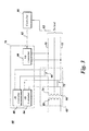
- FIG. 3 shows an integrated power quality control system 60 in accordance with an embodiment of the present technique.
- Integrated power quality control system 60 includes a distribution transformer 62 having a primary winding 64, a first secondary winding 66, a second secondary winding 74, and a first compensation winding 68 and a second compensation winding 75.
- at least one compensation winding may be connected in series with primary winding 64.
- compensation windings 68, 75 share a magnetic core with distribution transformer 62 i.e., compensation windings 68, 75 are wound on the same core as primary winding 64 and secondary winding 66 and 74.
- the advantage of utilizing a common magnetic core is a space reduction and cost reduction for cooling and packaging of compensation windings 68, 75.
- a power electronic converter 78 controls voltage across compensation windings 68, 75 based on a reference voltage signal 82 resulting into control of a magnetic flux in the magnetic core and thus, voltage across secondary windings 66, 74 is controlled.
- the reference voltage signal 82 is generated by a controller 80 and is based on a feedback signal 83 from output terminals of distribution transformer 62.
- the feedback signal 83 may be a combination of voltage signals or current signals or combinations thereof obtained by voltage and/or current sensors (not shown).
- power electronic converter 78 includes single phase converters 88 and 84 coupled to compensation windings 68, 74 respectively to control voltage across compensation windings 68, 74. Furthermore, power electronic converter 78 may include another single phase converter 86 to charge a common direct current (DC) link (not shown) for all single phase converters 88, 84 and 86.
- Single phase converter 86 charges the common DC link by fetching active power from transformer 62. In one embodiment, to fetch active power from transformer 62 single phase converter 86 injects appropriate current at output terminals 70, 72.
- single phase converters 88, 84 and 86 may be bidirectional converters i.e., converters which convert power from alternating current (AC) to direct current (DC) and/or DC to AC.
- all converters 88, 84 and 86 are bidirectional, have a common DC link and exchange real or active power with distribution transformer 62. More often single phase converters 88 and 84 supply active power to distribution transformer 62 which results in discharging of the common DC link and then single phase converter 86 receives active power from distribution transformer 62 to charge the DC link back to its original stage.
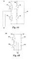
- FIG. 4a and FIG. 4b shows two exemplary single phase converters 90, 100 utilized in power electronic converters such as the power electronic converter 78 of FIG. 3 .
- Single phase converter 90 is a full bridge network made up of two parallel connected legs 97, 98 each having semiconductor devices 91, 92, and 93, 94 connected in series respectively.
- a DC link 95 is connected in parallel with the two legs 97, 98.
- An output connection 96 of single phase converter 90 is taken at mid-points of both legs 97, 98.
- Semiconductor devices may include insulated gate bipolar transistors (IGBTs) or metal oxide field effect transistors (MOSFETs).
- single phase converter 100 is a half bridge network made up of a split DC link 107 connected in parallel with a power converter leg 106.
- Power converter leg 106 includes two semiconductor devices 101 and 102 connected in series and split DC link 107 includes two DC link capacitors 103, 104 connected in series.
- An output connection 105 of single phase converter 100 is taken at mid-points of power converter leg 106 and split DC link 107.
- any of these single phase converter 90, 100 may be connected across the compensation windings to control its voltage or connected across two power terminals of a transformer to charge the DC link.
- other embodiments of single phase converters that occur to one skilled in the art are also within the scope of the system.
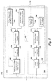
- FIG. 5 shows a controller 110 for power electronic converters of FIG. 4 in accordance with embodiments of the present technique.
- controller 110 includes compensation winding sub-controller 112 for single phase converter (82 or 84 of FIG. 3 ) which controls voltage across the compensation winding and DC link sub-controller 114 for single phase converter 86 ( FIG. 3 ) which controls the DC link.
- compensation winding sub-controller 112 may be used.
- Controller 110 receives feedback signals 116 such as output voltage and output current at each of the terminal of the distribution transformer 62 and a DC link voltage magnitude from power electronic converter 78.
- Compensation winding sub-controller 112 in this example includes a voltage magnitude and phase calculation module 118 which determines a magnitude and a phase of output voltage of distribution transformer 62.
- An error detection module 122 compares the magnitude and the phase of output voltage of distribution transformer 62 with a reference voltage magnitude and phase 120 to determine error signals 124. Error signals are then fed to proportional - integral (PI) controllers 126 which, based on error signals, determine magnitude and phase for a series voltage that are added to output voltage to obtain the reference voltage and reduce the error signal to approximately zero.
- PI proportional - integral
- An equivalent voltage generation and pulse width modulation (PWM) module 128 then generates PWM pulses for single phase converter 88 or 84. In one embodiment, turns ratio between the compensation winding and the secondary winding are also taken into consideration for generating the PWM pulses as discussed herein.
- V1 and V2 are voltages across transformer windings with number of turns equal to N1 and N2 respectively.
- Vser 10 volts need to be added in V2 to make it equal to the reference value which is 120 volts.
- voltage V2 can be adjusted by 10 volts by either increasing V1 by 300 volts or making V3 equal to 30 volts.
- equivalent voltage generation and PWM module 128 first calculates V3 from Vser determined by PI controllers 126 and then generates PWM pulses for single phase converter 88 or 84.
- the reference voltage magnitude and phase 120 is determined based on a power quality control requirement and is determined by the system operator or by another small controller (not shown).
- the power quality control requirement includes one of a voltage regulation, power factor correction, harmonic distortion compensation, and reactive power compensation.
- the power quality control requirement is voltage regulation
- a second controller may determine actual reactive power and compare it with reference reactive power to find out the reference voltage magnitude and phase.
- a second controller may be utilized for generating the reference voltage magnitude and phase in case of a harmonic compensation requirement.
- DC link sub-controller 114 includes an error detection module 130 which determines difference between actual DC voltage 132 and a reference DC voltage 134 and provides an error signal 136 to a PI controller 138.
- PI controller 138 determines a magnitude or amplitude modulation ratio for a PWM module 142 which then generates PWM pulses for single phase converter 86.
- compensation winding sub-controller 112 and DC link sub-controller 114 may be coupled as shown by a dotted line 113 and there may cross couple of some components.
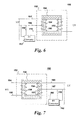
- FIG. 6 shows a schematic diagram of one embodiment of the integrated power quality control system 150.
- Integrated power quality control system 150 includes a transformer 152 having a primary winding 154 and a secondary winding 156 wound on a magnetic core 158.
- a compensation winding 160 is further wound on magnetic core 158 in continuation to primary winding 154.
- a power electronic converter 162 is connected in parallel across two input terminals 164, 166 of primary winding 154 and is controlled to receive active power from input terminals 164, 166 to charge a DC link as discussed herein.
- Output terminals 168, 170 of power electronic converter 162 are further connected across compensation winding 160.
- a controller (not shown) controls output voltage of power electronic converter 162 and accordingly changes voltage across compensation winding 160.
- compensation winding 160 changes a magnetic flux in transformer and accordingly it changes voltage across secondary winding 156.
- This technique can also be referred to as magnetic series compensation as a magnetic flux due to primary winding and a magnetic flux due to compensation windings get added for resultant magnetic flux in the transformer which changes the output voltage across secondary winding 156.
- the two magnetic fluxes get added which results in change in the output voltage.
- FIG. 7 shows a schematic diagram of another embodiment of an integrated power quality control system 180.
- the main difference compared to embodiment 150 of FIG. 6 is that compensation winding 160 is now connected in series with secondary winding 156 rather than in series with primary winding 154.
- power electronic converter input connections are connected in parallel to output terminals 165, 167 of secondary winding 156 and power electronic converter output connections 168, 170 are connected across compensation winding 160.
- FIG. 8 shows yet another embodiment of an integrated power quality control system 200.
- compensation winding 160 is neither connected in series with primary winding 154 nor in series with secondary winding 156 rather it is wound separately on magnetic core 158.
- the control of power electronic converter 162 in both embodiments 180 and 200 is similar to the control discussed herein.
- FIG. 9 shows a schematic representation of a three phase integrated power quality control system 250 in accordance with an embodiment of the present system.
- compensation windings discussed herein may also be employed in a three phase transformer.
- three phase integrated power quality control system 250 includes a three phase transformer 252 with primary windings 254 and secondary windings 256. Terminals A1, B1, and C1 form input terminals of transformer 252 whereas terminals a1, b1 and c1 form output terminals of transformer 252.
- Compensation windings 258 are connected in series with primary windings 254, however, in another embodiment, compensation windings 258 may also be connected in series with secondary windings 256.
- a power electronic converter 260 which may include a three phase converter that controls voltage across compensation windings 258 based on input signals from controller 262.
- Advantages of the present system and technical advantages include stable feeder voltage supply to loads, whether residential, business or government, improved power quality, no requirement of breaking the feeder lines and optimized size and cost of the system.
Landscapes
- Engineering & Computer Science (AREA)
- Power Engineering (AREA)
- Inverter Devices (AREA)
- Supply And Distribution Of Alternating Current (AREA)
- Control Of Electrical Variables (AREA)
- Dc-Dc Converters (AREA)
- Ac-Ac Conversion (AREA)
Abstract
Description
- Embodiments of the system relate generally to an electric power grid and more specifically to power quality in a distribution network.
- The basic structure of an electric power system comprises various hardware elements such as generators, transformers, and real-time monitoring equipment, and software such as power flow analysis software, fault detection software, and restoration software for generation, transmission, and distribution of electricity.
- With increased distributed generation, the integration of distributed generators into existing power systems presents technical challenges such as voltage regulation, stability, and power quality issues. Power quality is an essential customer-focused measure and is greatly affected by the operation of a distribution and transmission network.
- In general, power system operators ensure the quality of the power supplied to the customers by maintaining the load bus voltages within their permissible limits. Any changes to the system configuration or in power demands can result in higher or lower voltages in the system. In some situations the variability of the voltage level can be improved by reallocating the reactive power generated in the system such as by adjusting transformer taps and by switching volt-ampere reactive (VAR) sources such as capacitor banks. Another option is to use a series transformer to adjust the feeder voltages. However, transformer taps have limitations on the number of switchings per year and is not a satisfactory solution for frequent voltage variations. Furthermore, capacitor banks and the series transformer tend to require separate installations and may not work adequately for a lower reactance to resistance (X/R) ratio. Further the series transformer requires breaking the feeder line for installation.
- For these and other reasons, there is a need for an improved power quality control system.
- In accordance with one aspect of the present invention an integrated power quality control system is provided. The system includes a transformer including a primary winding, at least one secondary winding and at least one compensation winding wound on a magnetic core. The system further includes a power electronic converter providing a reference voltage to the compensation winding for injecting a series voltage in the secondary winding and a controller to generate the reference voltage for the power electronic converter based on a power quality control requirement.
- In accordance with another aspect of the present invention a method of controlling power to a load is provided. The method includes providing a transformer including a primary winding, at least one secondary winding and at least one compensation winding wound on a magnetic core and generating a reference voltage for a power electronic converter based on a power quality control requirement. The method further includes utilizing the power electronic converter to provide the reference voltage across the compensation winding for injecting a series voltage in the secondary winding.
- These and other features, aspects, and advantages of the present invention will become better understood when the following detailed description is read with reference to the accompanying drawings in which like characters represent like parts throughout the drawings, wherein:
-
FIG. 1 a is a single line diagram of a distribution system; -
FIG. 1b illustrates the effect of voltage drop based on the distance from the distribution sub-station; -
FIG. 2 is a schematic representation of a pole mounted distribution transformer; -
FIG. 3 is a schematic representation of an integrated power quality control system in accordance with an embodiment of the present system; -
FIG. 4a and 4b are schematic representation of two exemplary single phase converters utilized in a power electronic converter ofFIG. 3 in accordance with embodiments of the present system; -
FIG. 5 is a block diagram representation of a controller for power electronic converters in accordance with an embodiment of the present system; -
FIG. 6 is a schematic representation of one embodiment of the integrated power quality control system in accordance with an embodiment of the present system; -
FIG. 7 is a schematic diagram of another embodiment of the integrated power quality control system in accordance with an embodiment of the present system; -
FIG. 8 is a schematic representation of yet another embodiment of the integrated power quality control system in accordance with an embodiment of the present system; and -
FIG. 9 is a schematic representation of an embodiment of a three phase integrated power quality control system in accordance with an embodiment of the present system. - The embodiments described herein are directed to an integrated power quality control system that utilizes a distribution transformer with an active compensation winding therein to compensate for voltage fluctuations. While embodiments of the integrated power quality control system will be described in the context of the distribution transformer and for voltage fluctuations, it will be appreciated by those skilled in the art that the integrated power quality control system can be used with other transformers such as transmission transformer and for other applications such as a harmonic compensation as well.
- A power system typically comprises of three stages, namely i) generation, ii) transmission and iii) distribution. Power is generated typically in the range of 1 kV to 30 kV and then transmitted at higher voltage such as 230 kV - 765 kV to a distribution station. At the distribution station the voltage is again reduced to various levels in the range of 120 volts to 35 kV depending on the customer type. A number of transformers are utilized to transform/change the voltage levels from generating stations before it reaches the customers.
-
FIG. 1a illustrates a single line diagram of adistribution system 10 andFIG. 1b shows a simulation result representing corresponding graphical plot 30 of voltages at various load points indistribution system 10. Thedistribution system 10 includes adistribution substation 12 having adistribution transformer 14 andloads 16 connected to afeeder 18. Thedistribution substation 12 may receive power from one or more transmission substations (not shown).Distribution transformer 14 may be a three phase transformer or a single phase transformer depending on type ofload 16 i.e., industrial or residential.Distribution system 10 may further include a pole mounted distribution transformer (not shown) connected tofeeder 18 to supply power to loads 16. - Graphical plot 30 is a simulation result and shows two
graphs horizontal axis 32 in plot 30 represents a distance of theloads 16 fromdistribution substation 12 and avertical axis 34 represents voltage at the load point onfeeder 18. Thefeeder 18 has some amount of impedance per unit length (Z) which causes a voltage drop IZ volts per unit length, where I is the current flowing in the feeder. Thus,loads 16 connected along the length of thefeeder 18 will have different voltage levels, and the load at the far-end of thefeeder 18 has the lowest voltage. As can be seen fromplot 38, the voltage at thedistribution substation end 12 of the feeder is 1.02 pu. However, the voltage at feeder far-end for thecorresponding Load 3 is about 0.97 pu (e.g., residential customers would be seeing about 116 volts instead of 120). If the load were to increase, the far-end voltage would drop to an even lower value (i.e., from 1.02 pu to 0.96 pu) as can be seen fromgraph 36. - Another reason for load voltage fluctuation is variation in active and reactive power supplied by distributed generation such as solar and wind. For example, in one embodiment, solar power generation may be located at far end of
feeder 18. In such a case, a load variation may occur at center of the feeder. As a result, the system should regulate the voltage along thefeeder 18 in either direction for variations in load and distributed generations. -
FIG. 2 shows a schematic diagram of a pole mounteddistribution transformer 40 which supplies power to residential houses. Pole mounted distribution is a term that includes pole mounted distribution transformers, underground distribution transformers, as well as any comparable distribution system that is used to supply power to at least one load source such as residential houses, businesses, government offices, schools, and any combination thereof. Pole mounteddistribution transformer 40 includes aprimary winding 42 which receives power from distribution substation 12 (FIG. 1 ) typically at a medium voltage Vm. Asecondary winding 44 of pole mounteddistribution transformer 40 is a split phase winding. In this example,secondary winding 44 is split into two parts by acenter tap 46 ofsecondary winding 44. The rated voltage across secondary windings terminals P1 and P2 is generally a low voltage V1, which is less than the medium voltage Vm. In one embodiment, the medium voltage Vm may be 7200 volts and low voltage may be 240 volts. Thecenter tap 46 provides three wires on the secondary side. The three wires on the secondary side are a center tap N at, a secondary winding terminal P1 is at Vs1 volts with respect to center tap N, and another secondary winding terminal P2 is at Vs2 volts with respect to center tap N. In general, V1 is equal to the summation of of Vs1 and Vs2. - A load can be connected between terminals P1 and N for voltage output Vs1, between terminals P2 and N for Vs2 voltage output, and a V1 volts connection is obtained by connecting the load across the terminals P1 and P2. It should be understood that as the voltage across any of these terminals varies, loads connected to these terminals are affected. For example, lights may glow brighter or dimmer, and can even cause incandescent bulbs to blow prematurely. Poor power supply can also cause electronic equipment to fail (especially computers) and may cause interference of radio or television reception. In accordance with an embodiment of the present system, a compensation winding is included in
transformer 40 to regulate output voltage of thetransformer 40 so that customers can receive high quality power supply. -
FIG. 3 shows an integrated powerquality control system 60 in accordance with an embodiment of the present technique. Integrated powerquality control system 60 includes adistribution transformer 62 having a primary winding 64, a first secondary winding 66, a second secondary winding 74, and a first compensation winding 68 and a second compensation winding 75. In the embodiment shown, there are twocompensation windings output terminals - In one embodiment,
compensation windings distribution transformer 62 i.e.,compensation windings compensation windings electronic converter 78 controls voltage acrosscompensation windings reference voltage signal 82 resulting into control of a magnetic flux in the magnetic core and thus, voltage acrosssecondary windings reference voltage signal 82 is generated by acontroller 80 and is based on afeedback signal 83 from output terminals ofdistribution transformer 62. In one embodiment, thefeedback signal 83 may be a combination of voltage signals or current signals or combinations thereof obtained by voltage and/or current sensors (not shown). - In one embodiment, power
electronic converter 78 includessingle phase converters compensation windings compensation windings electronic converter 78 may include anothersingle phase converter 86 to charge a common direct current (DC) link (not shown) for allsingle phase converters Single phase converter 86 charges the common DC link by fetching active power fromtransformer 62. In one embodiment, to fetch active power fromtransformer 62single phase converter 86 injects appropriate current atoutput terminals single phase converters - In general, all
converters distribution transformer 62. More oftensingle phase converters distribution transformer 62 which results in discharging of the common DC link and thensingle phase converter 86 receives active power fromdistribution transformer 62 to charge the DC link back to its original stage. -
FIG. 4a and FIG. 4b shows two exemplarysingle phase converters electronic converter 78 ofFIG. 3 .Single phase converter 90 is a full bridge network made up of two parallelconnected legs semiconductor devices DC link 95 is connected in parallel with the twolegs output connection 96 ofsingle phase converter 90 is taken at mid-points of bothlegs - Referring to
FIG. 4b ,single phase converter 100 is a half bridge network made up of a split DC link 107 connected in parallel with apower converter leg 106.Power converter leg 106 includes twosemiconductor devices DC link 107 includes twoDC link capacitors output connection 105 ofsingle phase converter 100 is taken at mid-points ofpower converter leg 106 and splitDC link 107. As discussed herein any of thesesingle phase converter -
FIG. 5 shows acontroller 110 for power electronic converters ofFIG. 4 in accordance with embodiments of the present technique. In the embodiment shown,controller 110 includescompensation winding sub-controller 112 for single phase converter (82 or 84 ofFIG. 3 ) which controls voltage across the compensation winding andDC link sub-controller 114 for single phase converter 86 (FIG. 3 ) which controls the DC link. In one embodiment, where two compensation windings are utilized in the distribution transformer, twocompensation winding sub-controllers 112 may be used.Controller 110 receives feedback signals 116 such as output voltage and output current at each of the terminal of thedistribution transformer 62 and a DC link voltage magnitude from powerelectronic converter 78. -
Compensation winding sub-controller 112 in this example includes a voltage magnitude andphase calculation module 118 which determines a magnitude and a phase of output voltage ofdistribution transformer 62. Anerror detection module 122 compares the magnitude and the phase of output voltage ofdistribution transformer 62 with a reference voltage magnitude andphase 120 to determine error signals 124. Error signals are then fed to proportional - integral (PI)controllers 126 which, based on error signals, determine magnitude and phase for a series voltage that are added to output voltage to obtain the reference voltage and reduce the error signal to approximately zero. An equivalent voltage generation and pulse width modulation (PWM)module 128 then generates PWM pulses forsingle phase converter - For illustrative purposes, voltage ratio between two windings of a transformer can be given as V1/V2=N1/N2, where V1 and V2 are voltages across transformer windings with number of turns equal to N1 and N2 respectively. Assume a transformer secondary winding voltage is V2 (No center tap) and turns ratio N1/N2 between primary winding and secondary winding is 30/1 and turns ratio N3/N2 between compensation winding and secondary winding is 3/1. In one embodiment, V2 is set to be equal to 120 volts (i.e., V1=3600 volts), however, when measured V2 is actually 110 volts (i.e., V1=3300 volts). This suggests that a series voltage Vser of 10 volts need to be added in V2 to make it equal to the reference value which is 120 volts. In this case, voltage V2 can be adjusted by 10 volts by either increasing V1 by 300 volts or making V3 equal to 30 volts. Thus, equivalent voltage generation and
PWM module 128 first calculates V3 from Vser determined byPI controllers 126 and then generates PWM pulses forsingle phase converter - The reference voltage magnitude and
phase 120 is determined based on a power quality control requirement and is determined by the system operator or by another small controller (not shown). The power quality control requirement includes one of a voltage regulation, power factor correction, harmonic distortion compensation, and reactive power compensation. For example, if the power quality control requirement is voltage regulation, then the reference output voltage may be fed into the system by the operator and the reference voltage that needs to be injected may be determined by vector subtraction of the reference output voltage and the measured distribution transformer output voltage (i.e., Vser=Vref-V2). However, if the power quality control requirement is reactive power compensation, then a second controller may determine actual reactive power and compare it with reference reactive power to find out the reference voltage magnitude and phase. Similarly a second controller may be utilized for generating the reference voltage magnitude and phase in case of a harmonic compensation requirement. -
DC link sub-controller 114 includes anerror detection module 130 which determines difference betweenactual DC voltage 132 and areference DC voltage 134 and provides anerror signal 136 to aPI controller 138.PI controller 138 then determines a magnitude or amplitude modulation ratio for aPWM module 142 which then generates PWM pulses forsingle phase converter 86. - It should be noted that in
FIG. 5 , only an example controller is shown. However, other controllers to control voltage across the compensation winding or to control the DC link voltage and modification to the controller disclosed herein are within the scope of the present system. For example, in an embodiment (e.g., in case of a fault),compensation winding sub-controller 112 and DC link sub-controller 114 may be coupled as shown by a dottedline 113 and there may cross couple of some components. -
FIG. 6 shows a schematic diagram of one embodiment of the integrated powerquality control system 150. Integrated powerquality control system 150 includes atransformer 152 having a primary winding 154 and a secondary winding 156 wound on amagnetic core 158. A compensation winding 160 is further wound onmagnetic core 158 in continuation to primary winding 154. A powerelectronic converter 162 is connected in parallel across twoinput terminals input terminals Output terminals electronic converter 162 are further connected across compensation winding 160. A controller (not shown) controls output voltage of powerelectronic converter 162 and accordingly changes voltage across compensation winding 160. As the voltage across compensation winding 160 changes, it changes a magnetic flux in transformer and accordingly it changes voltage across secondary winding 156. This technique can also be referred to as magnetic series compensation as a magnetic flux due to primary winding and a magnetic flux due to compensation windings get added for resultant magnetic flux in the transformer which changes the output voltage across secondary winding 156. Thus, instead of addition of voltages, the two magnetic fluxes get added which results in change in the output voltage. -
FIG. 7 shows a schematic diagram of another embodiment of an integrated powerquality control system 180. In thisembodiment 180, the main difference compared toembodiment 150 ofFIG. 6 is that compensation winding 160 is now connected in series with secondary winding 156 rather than in series with primary winding 154. Furthermore, power electronic converter input connections are connected in parallel tooutput terminals converter output connections -
FIG. 8 shows yet another embodiment of an integrated powerquality control system 200. Inembodiment 200, compensation winding 160 is neither connected in series with primary winding 154 nor in series with secondary winding 156 rather it is wound separately onmagnetic core 158. The control of powerelectronic converter 162 in bothembodiments -
FIG. 9 shows a schematic representation of a three phase integrated powerquality control system 250 in accordance with an embodiment of the present system. In general, in this embodiment, compensation windings discussed herein may also be employed in a three phase transformer. Thus, three phase integrated powerquality control system 250 includes a threephase transformer 252 withprimary windings 254 andsecondary windings 256. Terminals A1, B1, and C1 form input terminals oftransformer 252 whereas terminals a1, b1 and c1 form output terminals oftransformer 252.Compensation windings 258 are connected in series withprimary windings 254, however, in another embodiment,compensation windings 258 may also be connected in series withsecondary windings 256. A powerelectronic converter 260 which may include a three phase converter that controls voltage acrosscompensation windings 258 based on input signals fromcontroller 262. - Advantages of the present system and technical advantages include stable feeder voltage supply to loads, whether residential, business or government, improved power quality, no requirement of breaking the feeder lines and optimized size and cost of the system.
- While only certain features of the invention have been illustrated and described herein, many modifications and changes will occur to those skilled in the art. It is, therefore, to be understood that the appended claims are intended to cover all such modifications and changes as fall within the true spirit of the invention.
- Various aspects and embodiments of the present invention are defined by the following numbered clauses:
- 1. An integrated power quality control system, comprising:
- a transformer including a primary winding, at least one secondary winding and at least one compensation winding wound on a magnetic core;
- a power electronic converter providing a reference voltage to the compensation winding for injecting a series voltage in the secondary winding; and
- a controller to generate the reference voltage for the power electronic converter based on a power quality control requirement.
- 2. The integrated power quality control system of
clause 1, wherein the compensation winding is connected in series with the primary winding or the secondary winding or is wound separately on the magnetic core. - 3. The integrated power quality control system of any preceding clause, wherein the compensation winding is configured to control a magnetic flux in the magnetic core for injecting the series voltage in the secondary winding.
- 4. The integrated power quality control system of any preceding clause, wherein the power electronic converter comprises a plurality of bidirectional converters utilizing a common DC link or a three phase converter.
- 5. The integrated power quality control system of any preceding clause, wherein at least one of the plurality of the bidirectional converters is connected across the primary winding or the secondary winding.
- 6. The integrated power quality control system of any preceding clause, wherein the transformer comprises a three phase transformer or a single phase transformer or a split phase secondary transformer.
- 7. The integrated power quality control system of any preceding clause, wherein the plurality of the bidirectional converters include a DC to AC converter to control the reference voltage across the compensation winding and a AC to DC converter for charging the common DC link by exchanging active power with the transformer.
- 8. The integrated power quality control system of any preceding clause, wherein the controller includes a first controller to control the DC to AC converter and a second controller to control the AC to DC converter.
- 9. The integrated power quality control system of any preceding clause, wherein the controller is configured to generate an amplitude modulation ratio for generating PWM pulses for the AC to DC converter based on an error between a reference DC voltage and an actual DC voltage.
- 10. The integrated power quality control system of any preceding clause, wherein the first controller is configured to generate the reference voltage based on a relationship between a turns ratio of the compensation winding and the secondary winding and a reference secondary winding voltage determined based on the power quality requirement.
- 11. The integrated power quality control system of any preceding clause, wherein the first controller includes a voltage magnitude and phase calculation module to determine a magnitude and a phase of a secondary winding voltage.
- 12. The integrated power quality control system of any preceding clause, wherein the first controller includes an error detection module to generate an error signal based on comparison of the magnitude and the phase of the secondary winding voltage with a magnitude and a phase of the reference secondary winding voltage.
- 13. The integrated power quality control system of any preceding clause, wherein the first controller includes proportional-integral (PI) controllers configured to reduce the error signal to zero.
- 14. The integrated power quality control system of any preceding clause, wherein the power quality control requirement includes one of a voltage regulation, power factor correction, harmonic distortion compensation, and reactive power compensation.
- 15. A method of controlling power to a load, comprising:
- providing a transformer including a primary winding, at least one secondary winding and at least one compensation winding wound on a magnetic core;
- generating a reference voltage for a power electronic converter based on a power quality control requirement; and
- utilizing the power electronic converter to provide the reference voltage across the compensation winding for injecting a series voltage in the secondary winding.
- 16. The method of controlling power to the load of any preceding clause, wherein providing a transformer comprises connecting the compensation winding in series with the primary winding or the secondary winding or is wound separately on the magnetic core.
- 17. The method of controlling power to the load of any preceding clause, wherein injecting the series voltage in the secondary winding comprises controlling a magnetic flux in the magnetic core.
- 18. The method of controlling power to the load of any preceding clause, wherein the power quality control requirement includes at least one of a voltage regulation, power factor correction, harmonic distortion compensation, and reactive power compensation.
- 19. The method of controlling power to the load of any preceding clause, wherein utilizing the power electronic converter comprises utilizing at least one bidirectional converter with a common DC link.
- 20. The method of controlling power to the load of any preceding clause, wherein utilizing the bidirectional converter includes utilizing a DC to AC converter to control the reference voltage across the compensation winding and a AC to DC converter for charging the common DC link by exchanging active power with the transformer.
Claims (15)
- An integrated power quality control system (60), comprising:a transformer (62) including a primary winding (64), at least one secondary winding (66, 74) and at least one compensation winding (68, 75) wound on a magnetic core (158);a power electronic converter (78) providing a reference voltage (82) to the compensation winding (68, 75) for injecting a series voltage in the secondary winding (66, 74); anda controller (80) to generate the reference voltage (82) for the power electronic converter (78) based on a power quality control requirement.
- The integrated power quality control system (60) of claim 1, wherein the compensation winding (68, 75) is connected in series with the primary winding (64) or the secondary winding (66, 74) or is wound separately on the magnetic core (158).
- The integrated power quality control system of claim 1 or 2, wherein the compensation winding (68, 75) is configured to control a magnetic flux in the magnetic core (158) for injecting the series voltage in the secondary winding (66, 74).
- The integrated power quality control system of any of claims 1 to 3, wherein the power electronic converter (78) comprises a plurality of bidirectional converters (84, 86, 88) utilizing a common DC link (95) or a three phase converter.
- The integrated power quality control system of claim 4, wherein the plurality of the bidirectional converters (84, 86, 88) include a DC to AC converter to control the reference voltage across the compensation winding (68, 75) and a AC to DC converter for charging the common DC link (95) by exchanging active power with the transformer (62).
- The integrated power quality control system of claim 5, wherein the controller (80) includes a first controller (112) to control the DC to AC converter and a second controller (114) to control the AC to DC converter.
- The integrated power quality control system of claim 6, wherein the controller (110) is configured to generate an amplitude modulation ratio for generating PWM pulses for the AC to DC converter (86) based on an error (136) between a reference DC voltage (134) and an actual DC voltage (132).
- The integrated power quality control system of claim 6, wherein the first controller (112) is configured to generate the reference voltage (134) based on a relationship between a turns ratio (N3/N2) of the compensation winding (68, 75) and the secondary winding (66, 74) and a reference secondary winding voltage determined based on the power quality requirement.
- The integrated power quality control system of any of claims 6 to 8, wherein the first controller (112) includes a voltage magnitude and phase calculation module (118) to determine a magnitude and a phase of a secondary winding voltage.
- The integrated power quality control system of claim 9, wherein the first controller (112) includes an error detection module (122) to generate an error signal (124) based on comparison of the magnitude and the phase (120) of the secondary winding voltage (132) with a magnitude and a phase of the reference secondary winding voltage (134).
- The integrated power quality control system of claim 10, wherein the first controller (112) includes proportional-integral (PI) controllers (126) configured to reduce the error signal to zero.
- The integrated power quality control system of any preceding claim, wherein the power quality control requirement includes one of a voltage regulation, power factor correction, harmonic distortion compensation, and reactive power compensation.
- A method of controlling power to a load, comprising:providing a transformer (62) including a primary winding (64), at least one secondary winding (66, 74) and at least one compensation winding (68, 75) wound on a magnetic core (158);generating a reference voltage for a power electronic converter (78) based on a power quality control requirement; andutilizing the power electronic converter (78) to provide the reference voltage (82) across the compensation winding (68, 75) for injecting a series voltage in the secondary winding (66, 74).
- The method of controlling power to the load of claim 13, wherein providing a transformer (62) comprises connecting the compensation winding (68, 75) in series with the primary winding (64) or the secondary winding (66, 74) or is wound separately on the magnetic core (158).
- The method of controlling power to the load of claim 13 or 14, wherein injecting the series voltage in the secondary winding (66, 76) comprises controlling a magnetic flux in the magnetic core (158).
Applications Claiming Priority (1)
| Application Number | Priority Date | Filing Date | Title |
|---|---|---|---|
| US13/678,052 US9042129B2 (en) | 2012-11-15 | 2012-11-15 | System and method for controlling power in a distribution system |
Publications (3)
| Publication Number | Publication Date |
|---|---|
| EP2733809A2 true EP2733809A2 (en) | 2014-05-21 |
| EP2733809A3 EP2733809A3 (en) | 2017-09-06 |
| EP2733809B1 EP2733809B1 (en) | 2020-09-23 |
Family
ID=49724444
Family Applications (1)
| Application Number | Title | Priority Date | Filing Date |
|---|---|---|---|
| EP13192880.6A Active EP2733809B1 (en) | 2012-11-15 | 2013-11-14 | Power quality control |
Country Status (8)
| Country | Link |
|---|---|
| US (1) | US9042129B2 (en) |
| EP (1) | EP2733809B1 (en) |
| CN (1) | CN103825278B (en) |
| AU (1) | AU2013257433B2 (en) |
| BR (1) | BR102013029291B1 (en) |
| CA (1) | CA2832574C (en) |
| MX (1) | MX2013013443A (en) |
| ZA (1) | ZA201308184B (en) |
Cited By (2)
| Publication number | Priority date | Publication date | Assignee | Title |
|---|---|---|---|---|
| WO2015198057A1 (en) * | 2014-06-25 | 2015-12-30 | Networked Electricity Storage Technology Ltd | Power control |
| CN106786628A (en) * | 2016-12-26 | 2017-05-31 | 陕西省地方电力设计有限公司 | A kind of controllable distribution transformer of stepless offset-type of voltage |
Families Citing this family (7)
| Publication number | Priority date | Publication date | Assignee | Title |
|---|---|---|---|---|
| US10116204B1 (en) * | 2012-12-21 | 2018-10-30 | Gridbridge, Inc. | Distribution transformer interface apparatus and methods |
| US10700597B1 (en) * | 2012-12-21 | 2020-06-30 | Gridbridge, Inc. | Distribution transformer power flow controller |
| CN108107396B (en) * | 2017-08-01 | 2024-06-04 | 国网江西省电力公司电力科学研究院 | Current transformer error detection device for compensating leakage current |
| CN112874302B (en) * | 2019-11-29 | 2022-10-18 | 比亚迪股份有限公司 | Method for controlling a rail vehicle auxiliary converter and rail vehicle |
| EP3840159B1 (en) | 2019-12-20 | 2023-08-23 | Hitachi Energy Switzerland AG | Transformer arrangement |
| CN111404175B (en) * | 2020-05-07 | 2023-04-18 | 国网湖南省电力有限公司 | Comprehensive treatment device and control method for low-voltage power quality of power distribution station area |
| CN112951566B (en) * | 2021-02-03 | 2023-03-21 | 陕西省地方电力(集团)有限公司延安供电分公司 | High-frequency full-control switch turn-ratio-variable current-voltage self-control transformer |
Family Cites Families (21)
| Publication number | Priority date | Publication date | Assignee | Title |
|---|---|---|---|---|
| US4001665A (en) * | 1975-04-21 | 1977-01-04 | Burroughs Corporation | High efficiency power supply having a reactive buck automatic d.c. voltage regulator |
| US5166597A (en) * | 1991-08-08 | 1992-11-24 | Electric Power Research Institute | Phase-shifting transformer system |
| US5329222A (en) * | 1992-11-30 | 1994-07-12 | Westinghouse Electric Corporation | Apparatus and method for dynamic voltage restoration of utility distribution networks |
| US5469044A (en) * | 1995-01-05 | 1995-11-21 | Westinghouse Electric Corporation | Transmission line power flow controller with unequal advancement and retardation of transmission angle |
| US6327162B1 (en) * | 1995-01-13 | 2001-12-04 | General Electric Company | Static series voltage regulator |
| US6021035A (en) * | 1995-05-31 | 2000-02-01 | General Electric Company | Apparatus for protection of power-electronics in series compensating systems |
| US5751138A (en) * | 1995-06-22 | 1998-05-12 | University Of Washington | Active power conditioner for reactive and harmonic compensation having PWM and stepped-wave inverters |
| US5754035A (en) * | 1997-01-14 | 1998-05-19 | Westinghouse Electric Corporation | Apparatus and method for controlling flow of power in a transmission line including stable reversal of power flow |
| US5883796A (en) * | 1997-04-07 | 1999-03-16 | Wisconsin Alumni Research Foundation | Dynamic series voltage restoration for sensitive loads in unbalanced power systems |
| EP0954082A3 (en) * | 1998-04-10 | 1999-11-24 | Kabushiki Kaisha Toshiba | AC transmission system |
| EP1168565A1 (en) * | 2000-06-30 | 2002-01-02 | ABB Industrie AG | Protection of a dynamic voltage restorer |
| JP2002218672A (en) * | 2001-01-15 | 2002-08-02 | Fuji Electric Co Ltd | Uninterruptible power system |
| JP4101788B2 (en) | 2004-05-25 | 2008-06-18 | 株式会社日立製作所 | Voltage adjusting device and voltage adjusting method |
| JP4643225B2 (en) | 2004-11-02 | 2011-03-02 | 中国電力株式会社 | Instantaneous voltage drop prevention device and instantaneous voltage drop prevention method |
| JP4673428B2 (en) * | 2006-06-30 | 2011-04-20 | アーベーベー・テヒノロギー・アーゲー | HVDC system and method for controlling voltage source converter of HVDC system |
| ATE533220T1 (en) * | 2007-09-14 | 2011-11-15 | Abb Technology Ag | STATCOM SYSTEM FOR PROVIDING REACTIVE AND/OR ACTIVE POWER TO A POWER NETWORK |
| CN101521385A (en) * | 2008-02-28 | 2009-09-02 | 西门子公司 | Dynamic voltage compensator for three-phase power supply system |
| WO2010091260A2 (en) * | 2009-02-06 | 2010-08-12 | Abb Research Ltd. | A hybrid distribution transformer with ac & dc power capabilities |
| US9325173B2 (en) * | 2009-09-15 | 2016-04-26 | The University Of Western Ontario | Utilization of distributed generator inverters as STATCOM |
| CN101695782B (en) | 2009-10-16 | 2011-11-09 | 无锡市南方电器制造有限公司 | Welding staring circuit of IGBT inverted gas protective welder |
| EP2541750A4 (en) * | 2010-02-26 | 2017-11-29 | Panasonic Intellectual Property Management Co., Ltd. | Power conversion apparatus, grid connection apparatus, and grid connection system |
-
2012
- 2012-11-15 US US13/678,052 patent/US9042129B2/en active Active
-
2013
- 2013-11-01 ZA ZA2013/08184A patent/ZA201308184B/en unknown
- 2013-11-07 CA CA2832574A patent/CA2832574C/en active Active
- 2013-11-13 AU AU2013257433A patent/AU2013257433B2/en not_active Ceased
- 2013-11-13 BR BR102013029291-5A patent/BR102013029291B1/en active IP Right Grant
- 2013-11-14 EP EP13192880.6A patent/EP2733809B1/en active Active
- 2013-11-15 MX MX2013013443A patent/MX2013013443A/en active IP Right Grant
- 2013-11-15 CN CN201310568399.9A patent/CN103825278B/en active Active
Non-Patent Citations (1)
| Title |
|---|
| None |
Cited By (3)
| Publication number | Priority date | Publication date | Assignee | Title |
|---|---|---|---|---|
| WO2015198057A1 (en) * | 2014-06-25 | 2015-12-30 | Networked Electricity Storage Technology Ltd | Power control |
| CN106786628A (en) * | 2016-12-26 | 2017-05-31 | 陕西省地方电力设计有限公司 | A kind of controllable distribution transformer of stepless offset-type of voltage |
| CN106786628B (en) * | 2016-12-26 | 2019-06-21 | 陕西省地方电力设计有限公司 | A voltage stepless compensation type controllable distribution transformer |
Also Published As
| Publication number | Publication date |
|---|---|
| EP2733809A3 (en) | 2017-09-06 |
| US9042129B2 (en) | 2015-05-26 |
| BR102013029291A2 (en) | 2015-09-22 |
| AU2013257433B2 (en) | 2017-05-04 |
| ZA201308184B (en) | 2016-02-24 |
| MX2013013443A (en) | 2014-07-03 |
| CN103825278A (en) | 2014-05-28 |
| CN103825278B (en) | 2018-06-12 |
| CA2832574C (en) | 2021-01-26 |
| EP2733809B1 (en) | 2020-09-23 |
| US20140133185A1 (en) | 2014-05-15 |
| CA2832574A1 (en) | 2014-05-15 |
| BR102013029291B1 (en) | 2021-02-09 |
| AU2013257433A1 (en) | 2014-05-29 |
Similar Documents
| Publication | Publication Date | Title |
|---|---|---|
| US9042129B2 (en) | System and method for controlling power in a distribution system | |
| US12062910B2 (en) | Two-way electrical power distribution network | |
| Mura et al. | Design aspects of a medium-voltage direct current (MVDC) grid for a university campus | |
| US10389125B2 (en) | Expanded reactive following for distributed generation and loads of other reactive controller(s) | |
| Van Der Merwe et al. | The solid-state transformer concept: A new era in power distribution | |
| US11146068B2 (en) | Method and apparatus for minimizing circulating currents in microgrids | |
| JP6693595B1 (en) | Grid interconnection device | |
| Hatziargyriou et al. | On the der hosting capacity of distribution feeders | |
| US20190028023A1 (en) | Distribution transformer interface apparatus and methods | |
| Ramamurthy et al. | Mitigation of motor starting voltage sags using distribution-class statcom | |
| Chen et al. | Flexible transformers for distribution grid control | |
| JP2012237573A (en) | Calculation device for impedance of low-voltage distribution line | |
| JP2012125020A (en) | Voltage regulating device | |
| Sarimuthu et al. | Impact of distributed generation on voltage profile in radial feeder | |
| US12614662B1 (en) | Alternating current quantum magnetic transformer and related energy saving device and methods | |
| Bhola et al. | Reactive Power Compensation in 132kv & 33kv Grid of Narsinghpur Area | |
| Roy et al. | A paper of determination of controlling characteristics of the monopolar HVDC system | |
| Li et al. | Voltage balancing in low voltage distribution networks using Scott transforners | |
| Cincar et al. | Devices for improving voltage conditions in low-voltage electrical distribution networks | |
| Nye et al. | Generation increase on distribution feeders using electronic voltage regulators | |
| Verbytskyi | DC and AC power grids with alternative energy sources-2: Practice notes | |
| Poulimenos et al. | Comparative Analysis of Distributed Generation Control Methods to Enhance DG Penetration in Power Distribution Grids | |
| Ghulbet et al. | An Investigation on Harmonic Problems for N-1 Contingency in Industrial Distribution and Its Mitigation Using Fuzzy Controlled Hybrid Filter | |
| Dyussembekova et al. | Monitoring places of installation of compensating devices in the network as a means of improving energy effeciency | |
| Bryantsev et al. | Regulated reactive-power sources with biasing-controlled shunting reactors and capacitor banks |
Legal Events
| Date | Code | Title | Description |
|---|---|---|---|
| PUAI | Public reference made under article 153(3) epc to a published international application that has entered the european phase |
Free format text: ORIGINAL CODE: 0009012 |
|
| 17P | Request for examination filed |
Effective date: 20131114 |
|
| AK | Designated contracting states |
Kind code of ref document: A2 Designated state(s): AL AT BE BG CH CY CZ DE DK EE ES FI FR GB GR HR HU IE IS IT LI LT LU LV MC MK MT NL NO PL PT RO RS SE SI SK SM TR |
|
| AX | Request for extension of the european patent |
Extension state: BA ME |
|
| PUAL | Search report despatched |
Free format text: ORIGINAL CODE: 0009013 |
|
| AK | Designated contracting states |
Kind code of ref document: A3 Designated state(s): AL AT BE BG CH CY CZ DE DK EE ES FI FR GB GR HR HU IE IS IT LI LT LU LV MC MK MT NL NO PL PT RO RS SE SI SK SM TR |
|
| AX | Request for extension of the european patent |
Extension state: BA ME |
|
| RIC1 | Information provided on ipc code assigned before grant |
Ipc: H02J 3/18 20060101ALI20170801BHEP Ipc: H02J 3/00 20060101AFI20170801BHEP |
|
| STAA | Information on the status of an ep patent application or granted ep patent |
Free format text: STATUS: REQUEST FOR EXAMINATION WAS MADE |
|
| R17P | Request for examination filed (corrected) |
Effective date: 20180306 |
|
| RBV | Designated contracting states (corrected) |
Designated state(s): AL AT BE BG CH CY CZ DE DK EE ES FI FR GB GR HR HU IE IS IT LI LT LU LV MC MK MT NL NO PL PT RO RS SE SI SK SM TR |
|
| STAA | Information on the status of an ep patent application or granted ep patent |
Free format text: STATUS: EXAMINATION IS IN PROGRESS |
|
| 17Q | First examination report despatched |
Effective date: 20190531 |
|
| GRAP | Despatch of communication of intention to grant a patent |
Free format text: ORIGINAL CODE: EPIDOSNIGR1 |
|
| STAA | Information on the status of an ep patent application or granted ep patent |
Free format text: STATUS: GRANT OF PATENT IS INTENDED |
|
| INTG | Intention to grant announced |
Effective date: 20200420 |
|
| GRAS | Grant fee paid |
Free format text: ORIGINAL CODE: EPIDOSNIGR3 |
|
| GRAA | (expected) grant |
Free format text: ORIGINAL CODE: 0009210 |
|
| STAA | Information on the status of an ep patent application or granted ep patent |
Free format text: STATUS: THE PATENT HAS BEEN GRANTED |
|
| AK | Designated contracting states |
Kind code of ref document: B1 Designated state(s): AL AT BE BG CH CY CZ DE DK EE ES FI FR GB GR HR HU IE IS IT LI LT LU LV MC MK MT NL NO PL PT RO RS SE SI SK SM TR |
|
| REG | Reference to a national code |
Ref country code: GB Ref legal event code: FG4D |
|
| REG | Reference to a national code |
Ref country code: CH Ref legal event code: EP |
|
| REG | Reference to a national code |
Ref country code: IE Ref legal event code: FG4D |
|
| REG | Reference to a national code |
Ref country code: DE Ref legal event code: R096 Ref document number: 602013072720 Country of ref document: DE Ref country code: AT Ref legal event code: REF Ref document number: 1317354 Country of ref document: AT Kind code of ref document: T Effective date: 20201015 |
|
| REG | Reference to a national code |
Ref country code: SE Ref legal event code: TRGR |
|
| PG25 | Lapsed in a contracting state [announced via postgrant information from national office to epo] |
Ref country code: BG Free format text: LAPSE BECAUSE OF FAILURE TO SUBMIT A TRANSLATION OF THE DESCRIPTION OR TO PAY THE FEE WITHIN THE PRESCRIBED TIME-LIMIT Effective date: 20201223 Ref country code: HR Free format text: LAPSE BECAUSE OF FAILURE TO SUBMIT A TRANSLATION OF THE DESCRIPTION OR TO PAY THE FEE WITHIN THE PRESCRIBED TIME-LIMIT Effective date: 20200923 Ref country code: FI Free format text: LAPSE BECAUSE OF FAILURE TO SUBMIT A TRANSLATION OF THE DESCRIPTION OR TO PAY THE FEE WITHIN THE PRESCRIBED TIME-LIMIT Effective date: 20200923 Ref country code: GR Free format text: LAPSE BECAUSE OF FAILURE TO SUBMIT A TRANSLATION OF THE DESCRIPTION OR TO PAY THE FEE WITHIN THE PRESCRIBED TIME-LIMIT Effective date: 20201224 Ref country code: NO Free format text: LAPSE BECAUSE OF FAILURE TO SUBMIT A TRANSLATION OF THE DESCRIPTION OR TO PAY THE FEE WITHIN THE PRESCRIBED TIME-LIMIT Effective date: 20201223 |
|
| REG | Reference to a national code |
Ref country code: AT Ref legal event code: MK05 Ref document number: 1317354 Country of ref document: AT Kind code of ref document: T Effective date: 20200923 |
|
| PG25 | Lapsed in a contracting state [announced via postgrant information from national office to epo] |
Ref country code: RS Free format text: LAPSE BECAUSE OF FAILURE TO SUBMIT A TRANSLATION OF THE DESCRIPTION OR TO PAY THE FEE WITHIN THE PRESCRIBED TIME-LIMIT Effective date: 20200923 Ref country code: LV Free format text: LAPSE BECAUSE OF FAILURE TO SUBMIT A TRANSLATION OF THE DESCRIPTION OR TO PAY THE FEE WITHIN THE PRESCRIBED TIME-LIMIT Effective date: 20200923 |
|
| REG | Reference to a national code |
Ref country code: NL Ref legal event code: MP Effective date: 20200923 |
|
| REG | Reference to a national code |
Ref country code: LT Ref legal event code: MG4D |
|
| PG25 | Lapsed in a contracting state [announced via postgrant information from national office to epo] |
Ref country code: EE Free format text: LAPSE BECAUSE OF FAILURE TO SUBMIT A TRANSLATION OF THE DESCRIPTION OR TO PAY THE FEE WITHIN THE PRESCRIBED TIME-LIMIT Effective date: 20200923 Ref country code: CZ Free format text: LAPSE BECAUSE OF FAILURE TO SUBMIT A TRANSLATION OF THE DESCRIPTION OR TO PAY THE FEE WITHIN THE PRESCRIBED TIME-LIMIT Effective date: 20200923 Ref country code: SM Free format text: LAPSE BECAUSE OF FAILURE TO SUBMIT A TRANSLATION OF THE DESCRIPTION OR TO PAY THE FEE WITHIN THE PRESCRIBED TIME-LIMIT Effective date: 20200923 Ref country code: RO Free format text: LAPSE BECAUSE OF FAILURE TO SUBMIT A TRANSLATION OF THE DESCRIPTION OR TO PAY THE FEE WITHIN THE PRESCRIBED TIME-LIMIT Effective date: 20200923 Ref country code: LT Free format text: LAPSE BECAUSE OF FAILURE TO SUBMIT A TRANSLATION OF THE DESCRIPTION OR TO PAY THE FEE WITHIN THE PRESCRIBED TIME-LIMIT Effective date: 20200923 Ref country code: PT Free format text: LAPSE BECAUSE OF FAILURE TO SUBMIT A TRANSLATION OF THE DESCRIPTION OR TO PAY THE FEE WITHIN THE PRESCRIBED TIME-LIMIT Effective date: 20210125 Ref country code: NL Free format text: LAPSE BECAUSE OF FAILURE TO SUBMIT A TRANSLATION OF THE DESCRIPTION OR TO PAY THE FEE WITHIN THE PRESCRIBED TIME-LIMIT Effective date: 20200923 |
|
| PG25 | Lapsed in a contracting state [announced via postgrant information from national office to epo] |
Ref country code: AT Free format text: LAPSE BECAUSE OF FAILURE TO SUBMIT A TRANSLATION OF THE DESCRIPTION OR TO PAY THE FEE WITHIN THE PRESCRIBED TIME-LIMIT Effective date: 20200923 Ref country code: AL Free format text: LAPSE BECAUSE OF FAILURE TO SUBMIT A TRANSLATION OF THE DESCRIPTION OR TO PAY THE FEE WITHIN THE PRESCRIBED TIME-LIMIT Effective date: 20200923 Ref country code: ES Free format text: LAPSE BECAUSE OF FAILURE TO SUBMIT A TRANSLATION OF THE DESCRIPTION OR TO PAY THE FEE WITHIN THE PRESCRIBED TIME-LIMIT Effective date: 20200923 Ref country code: PL Free format text: LAPSE BECAUSE OF FAILURE TO SUBMIT A TRANSLATION OF THE DESCRIPTION OR TO PAY THE FEE WITHIN THE PRESCRIBED TIME-LIMIT Effective date: 20200923 Ref country code: IS Free format text: LAPSE BECAUSE OF FAILURE TO SUBMIT A TRANSLATION OF THE DESCRIPTION OR TO PAY THE FEE WITHIN THE PRESCRIBED TIME-LIMIT Effective date: 20210123 |
|
| REG | Reference to a national code |
Ref country code: DE Ref legal event code: R097 Ref document number: 602013072720 Country of ref document: DE |
|
| PG25 | Lapsed in a contracting state [announced via postgrant information from national office to epo] |
Ref country code: MC Free format text: LAPSE BECAUSE OF FAILURE TO SUBMIT A TRANSLATION OF THE DESCRIPTION OR TO PAY THE FEE WITHIN THE PRESCRIBED TIME-LIMIT Effective date: 20200923 Ref country code: SK Free format text: LAPSE BECAUSE OF FAILURE TO SUBMIT A TRANSLATION OF THE DESCRIPTION OR TO PAY THE FEE WITHIN THE PRESCRIBED TIME-LIMIT Effective date: 20200923 |
|
| REG | Reference to a national code |
Ref country code: CH Ref legal event code: PL |
|
| PG25 | Lapsed in a contracting state [announced via postgrant information from national office to epo] |
Ref country code: LU Free format text: LAPSE BECAUSE OF NON-PAYMENT OF DUE FEES Effective date: 20201114 |
|
| PLBE | No opposition filed within time limit |
Free format text: ORIGINAL CODE: 0009261 |
|
| STAA | Information on the status of an ep patent application or granted ep patent |
Free format text: STATUS: NO OPPOSITION FILED WITHIN TIME LIMIT |
|
| REG | Reference to a national code |
Ref country code: BE Ref legal event code: MM Effective date: 20201130 |
|
| PG25 | Lapsed in a contracting state [announced via postgrant information from national office to epo] |
Ref country code: SI Free format text: LAPSE BECAUSE OF FAILURE TO SUBMIT A TRANSLATION OF THE DESCRIPTION OR TO PAY THE FEE WITHIN THE PRESCRIBED TIME-LIMIT Effective date: 20200923 Ref country code: LI Free format text: LAPSE BECAUSE OF NON-PAYMENT OF DUE FEES Effective date: 20201130 Ref country code: CH Free format text: LAPSE BECAUSE OF NON-PAYMENT OF DUE FEES Effective date: 20201130 Ref country code: DK Free format text: LAPSE BECAUSE OF FAILURE TO SUBMIT A TRANSLATION OF THE DESCRIPTION OR TO PAY THE FEE WITHIN THE PRESCRIBED TIME-LIMIT Effective date: 20200923 |
|
| 26N | No opposition filed |
Effective date: 20210624 |
|
| PG25 | Lapsed in a contracting state [announced via postgrant information from national office to epo] |
Ref country code: IT Free format text: LAPSE BECAUSE OF FAILURE TO SUBMIT A TRANSLATION OF THE DESCRIPTION OR TO PAY THE FEE WITHIN THE PRESCRIBED TIME-LIMIT Effective date: 20200923 Ref country code: IE Free format text: LAPSE BECAUSE OF NON-PAYMENT OF DUE FEES Effective date: 20201114 Ref country code: FR Free format text: LAPSE BECAUSE OF NON-PAYMENT OF DUE FEES Effective date: 20201123 |
|
| PG25 | Lapsed in a contracting state [announced via postgrant information from national office to epo] |
Ref country code: TR Free format text: LAPSE BECAUSE OF FAILURE TO SUBMIT A TRANSLATION OF THE DESCRIPTION OR TO PAY THE FEE WITHIN THE PRESCRIBED TIME-LIMIT Effective date: 20200923 Ref country code: MT Free format text: LAPSE BECAUSE OF FAILURE TO SUBMIT A TRANSLATION OF THE DESCRIPTION OR TO PAY THE FEE WITHIN THE PRESCRIBED TIME-LIMIT Effective date: 20200923 Ref country code: CY Free format text: LAPSE BECAUSE OF FAILURE TO SUBMIT A TRANSLATION OF THE DESCRIPTION OR TO PAY THE FEE WITHIN THE PRESCRIBED TIME-LIMIT Effective date: 20200923 |
|
| PG25 | Lapsed in a contracting state [announced via postgrant information from national office to epo] |
Ref country code: MK Free format text: LAPSE BECAUSE OF FAILURE TO SUBMIT A TRANSLATION OF THE DESCRIPTION OR TO PAY THE FEE WITHIN THE PRESCRIBED TIME-LIMIT Effective date: 20200923 |
|
| PG25 | Lapsed in a contracting state [announced via postgrant information from national office to epo] |
Ref country code: BE Free format text: LAPSE BECAUSE OF NON-PAYMENT OF DUE FEES Effective date: 20201130 |
|
| P01 | Opt-out of the competence of the unified patent court (upc) registered |
Effective date: 20230522 |
|
| REG | Reference to a national code |
Ref country code: DE Ref legal event code: R081 Ref document number: 602013072720 Country of ref document: DE Owner name: GENERAL ELECTRIC TECHNOLOGY GMBH, CH Free format text: FORMER OWNER: GENERAL ELECTRIC COMPANY, SCHENECTADY, NY, US |
|
| REG | Reference to a national code |
Ref country code: GB Ref legal event code: 732E Free format text: REGISTERED BETWEEN 20240222 AND 20240228 |
|
| PGFP | Annual fee paid to national office [announced via postgrant information from national office to epo] |
Ref country code: DE Payment date: 20251022 Year of fee payment: 13 |
|
| PGFP | Annual fee paid to national office [announced via postgrant information from national office to epo] |
Ref country code: GB Payment date: 20251023 Year of fee payment: 13 |
|
| PGFP | Annual fee paid to national office [announced via postgrant information from national office to epo] |
Ref country code: SE Payment date: 20251022 Year of fee payment: 13 |