EP2733797B1 - Spark plug - Google Patents
Spark plug Download PDFInfo
- Publication number
- EP2733797B1 EP2733797B1 EP12810850.3A EP12810850A EP2733797B1 EP 2733797 B1 EP2733797 B1 EP 2733797B1 EP 12810850 A EP12810850 A EP 12810850A EP 2733797 B1 EP2733797 B1 EP 2733797B1
- Authority
- EP
- European Patent Office
- Prior art keywords
- gasket
- spark plug
- loosening
- metallic shell
- nickel
- Prior art date
- Legal status (The legal status is an assumption and is not a legal conclusion. Google has not performed a legal analysis and makes no representation as to the accuracy of the status listed.)
- Active
Links
- PXHVJJICTQNCMI-UHFFFAOYSA-N Nickel Chemical compound [Ni] PXHVJJICTQNCMI-UHFFFAOYSA-N 0.000 claims description 39
- 229910052759 nickel Inorganic materials 0.000 claims description 18
- 239000011135 tin Substances 0.000 claims description 17
- 239000010949 copper Substances 0.000 claims description 12
- 229910052698 phosphorus Inorganic materials 0.000 claims description 11
- 229910052718 tin Inorganic materials 0.000 claims description 10
- RYGMFSIKBFXOCR-UHFFFAOYSA-N Copper Chemical compound [Cu] RYGMFSIKBFXOCR-UHFFFAOYSA-N 0.000 claims description 9
- 229910052802 copper Inorganic materials 0.000 claims description 9
- OAICVXFJPJFONN-UHFFFAOYSA-N Phosphorus Chemical compound [P] OAICVXFJPJFONN-UHFFFAOYSA-N 0.000 claims description 8
- ATJFFYVFTNAWJD-UHFFFAOYSA-N Tin Chemical compound [Sn] ATJFFYVFTNAWJD-UHFFFAOYSA-N 0.000 claims description 8
- 239000011574 phosphorus Substances 0.000 claims description 8
- 239000007787 solid Substances 0.000 claims description 5
- 230000002093 peripheral effect Effects 0.000 claims description 3
- 235000019589 hardness Nutrition 0.000 description 19
- 239000012212 insulator Substances 0.000 description 18
- 238000011156 evaluation Methods 0.000 description 12
- 239000000463 material Substances 0.000 description 10
- 238000012360 testing method Methods 0.000 description 9
- 239000011159 matrix material Substances 0.000 description 8
- 229910052782 aluminium Inorganic materials 0.000 description 7
- XAGFODPZIPBFFR-UHFFFAOYSA-N aluminium Chemical compound [Al] XAGFODPZIPBFFR-UHFFFAOYSA-N 0.000 description 7
- 238000002485 combustion reaction Methods 0.000 description 7
- 238000007789 sealing Methods 0.000 description 7
- 238000012986 modification Methods 0.000 description 6
- 230000004048 modification Effects 0.000 description 6
- 230000001747 exhibiting effect Effects 0.000 description 5
- 230000001629 suppression Effects 0.000 description 5
- UQMRAFJOBWOFNS-UHFFFAOYSA-N butyl 2-(2,4-dichlorophenoxy)acetate Chemical group CCCCOC(=O)COC1=CC=C(Cl)C=C1Cl UQMRAFJOBWOFNS-UHFFFAOYSA-N 0.000 description 4
- 230000000694 effects Effects 0.000 description 4
- 238000012856 packing Methods 0.000 description 4
- 239000000454 talc Substances 0.000 description 4
- 229910052623 talc Inorganic materials 0.000 description 4
- 229910000881 Cu alloy Inorganic materials 0.000 description 3
- KDLHZDBZIXYQEI-UHFFFAOYSA-N Palladium Chemical compound [Pd] KDLHZDBZIXYQEI-UHFFFAOYSA-N 0.000 description 3
- 238000000137 annealing Methods 0.000 description 3
- 238000001816 cooling Methods 0.000 description 3
- 230000007423 decrease Effects 0.000 description 3
- 238000000034 method Methods 0.000 description 3
- 239000000203 mixture Substances 0.000 description 3
- BASFCYQUMIYNBI-UHFFFAOYSA-N platinum Chemical compound [Pt] BASFCYQUMIYNBI-UHFFFAOYSA-N 0.000 description 3
- 229910045601 alloy Inorganic materials 0.000 description 2
- 239000000956 alloy Substances 0.000 description 2
- 239000000919 ceramic Substances 0.000 description 2
- 230000006835 compression Effects 0.000 description 2
- 238000007906 compression Methods 0.000 description 2
- 239000000446 fuel Substances 0.000 description 2
- 238000010438 heat treatment Methods 0.000 description 2
- 229910001026 inconel Inorganic materials 0.000 description 2
- 238000004519 manufacturing process Methods 0.000 description 2
- 238000003825 pressing Methods 0.000 description 2
- 239000010948 rhodium Substances 0.000 description 2
- 238000005204 segregation Methods 0.000 description 2
- 229910000575 Ir alloy Inorganic materials 0.000 description 1
- 229910001209 Low-carbon steel Inorganic materials 0.000 description 1
- 229910000990 Ni alloy Inorganic materials 0.000 description 1
- KJTLSVCANCCWHF-UHFFFAOYSA-N Ruthenium Chemical compound [Ru] KJTLSVCANCCWHF-UHFFFAOYSA-N 0.000 description 1
- 238000007545 Vickers hardness test Methods 0.000 description 1
- 230000001133 acceleration Effects 0.000 description 1
- PNEYBMLMFCGWSK-UHFFFAOYSA-N aluminium oxide Inorganic materials [O-2].[O-2].[O-2].[Al+3].[Al+3] PNEYBMLMFCGWSK-UHFFFAOYSA-N 0.000 description 1
- 238000005452 bending Methods 0.000 description 1
- 239000000567 combustion gas Substances 0.000 description 1
- 238000005260 corrosion Methods 0.000 description 1
- 230000007797 corrosion Effects 0.000 description 1
- 238000002788 crimping Methods 0.000 description 1
- 230000003247 decreasing effect Effects 0.000 description 1
- 238000009760 electrical discharge machining Methods 0.000 description 1
- 238000002474 experimental method Methods 0.000 description 1
- 238000001125 extrusion Methods 0.000 description 1
- 230000002349 favourable effect Effects 0.000 description 1
- 238000010304 firing Methods 0.000 description 1
- 230000017525 heat dissipation Effects 0.000 description 1
- 238000010348 incorporation Methods 0.000 description 1
- 239000011810 insulating material Substances 0.000 description 1
- 229910052741 iridium Inorganic materials 0.000 description 1
- GKOZUEZYRPOHIO-UHFFFAOYSA-N iridium atom Chemical compound [Ir] GKOZUEZYRPOHIO-UHFFFAOYSA-N 0.000 description 1
- 229910052751 metal Inorganic materials 0.000 description 1
- 239000002184 metal Substances 0.000 description 1
- 229910000510 noble metal Inorganic materials 0.000 description 1
- 229910052763 palladium Inorganic materials 0.000 description 1
- 229910052697 platinum Inorganic materials 0.000 description 1
- 239000000843 powder Substances 0.000 description 1
- 229910052702 rhenium Inorganic materials 0.000 description 1
- WUAPFZMCVAUBPE-UHFFFAOYSA-N rhenium atom Chemical compound [Re] WUAPFZMCVAUBPE-UHFFFAOYSA-N 0.000 description 1
- 229910052703 rhodium Inorganic materials 0.000 description 1
- MHOVAHRLVXNVSD-UHFFFAOYSA-N rhodium atom Chemical compound [Rh] MHOVAHRLVXNVSD-UHFFFAOYSA-N 0.000 description 1
- 229910052707 ruthenium Inorganic materials 0.000 description 1
- 238000004088 simulation Methods 0.000 description 1
- 239000006104 solid solution Substances 0.000 description 1
- 238000003466 welding Methods 0.000 description 1
Images


Classifications
-
- F—MECHANICAL ENGINEERING; LIGHTING; HEATING; WEAPONS; BLASTING
- F16—ENGINEERING ELEMENTS AND UNITS; GENERAL MEASURES FOR PRODUCING AND MAINTAINING EFFECTIVE FUNCTIONING OF MACHINES OR INSTALLATIONS; THERMAL INSULATION IN GENERAL
- F16J—PISTONS; CYLINDERS; SEALINGS
- F16J15/00—Sealings
- F16J15/02—Sealings between relatively-stationary surfaces
- F16J15/06—Sealings between relatively-stationary surfaces with solid packing compressed between sealing surfaces
- F16J15/061—Sealings between relatively-stationary surfaces with solid packing compressed between sealing surfaces with positioning means
-
- F—MECHANICAL ENGINEERING; LIGHTING; HEATING; WEAPONS; BLASTING
- F16—ENGINEERING ELEMENTS AND UNITS; GENERAL MEASURES FOR PRODUCING AND MAINTAINING EFFECTIVE FUNCTIONING OF MACHINES OR INSTALLATIONS; THERMAL INSULATION IN GENERAL
- F16J—PISTONS; CYLINDERS; SEALINGS
- F16J15/00—Sealings
- F16J15/02—Sealings between relatively-stationary surfaces
- F16J15/06—Sealings between relatively-stationary surfaces with solid packing compressed between sealing surfaces
- F16J15/08—Sealings between relatively-stationary surfaces with solid packing compressed between sealing surfaces with exclusively metal packing
- F16J15/0881—Sealings between relatively-stationary surfaces with solid packing compressed between sealing surfaces with exclusively metal packing the sealing effect being obtained by plastic deformation of the packing
-
- H—ELECTRICITY
- H01—ELECTRIC ELEMENTS
- H01T—SPARK GAPS; OVERVOLTAGE ARRESTERS USING SPARK GAPS; SPARKING PLUGS; CORONA DEVICES; GENERATING IONS TO BE INTRODUCED INTO NON-ENCLOSED GASES
- H01T13/00—Sparking plugs
- H01T13/02—Details
- H01T13/08—Mounting, fixing or sealing of sparking plugs, e.g. in combustion chamber
-
- H—ELECTRICITY
- H01—ELECTRIC ELEMENTS
- H01L—SEMICONDUCTOR DEVICES NOT COVERED BY CLASS H10
- H01L2224/00—Indexing scheme for arrangements for connecting or disconnecting semiconductor or solid-state bodies and methods related thereto as covered by H01L24/00
- H01L2224/01—Means for bonding being attached to, or being formed on, the surface to be connected, e.g. chip-to-package, die-attach, "first-level" interconnects; Manufacturing methods related thereto
- H01L2224/26—Layer connectors, e.g. plate connectors, solder or adhesive layers; Manufacturing methods related thereto
- H01L2224/31—Structure, shape, material or disposition of the layer connectors after the connecting process
- H01L2224/32—Structure, shape, material or disposition of the layer connectors after the connecting process of an individual layer connector
- H01L2224/321—Disposition
- H01L2224/32151—Disposition the layer connector connecting between a semiconductor or solid-state body and an item not being a semiconductor or solid-state body, e.g. chip-to-substrate, chip-to-passive
- H01L2224/32221—Disposition the layer connector connecting between a semiconductor or solid-state body and an item not being a semiconductor or solid-state body, e.g. chip-to-substrate, chip-to-passive the body and the item being stacked
- H01L2224/32245—Disposition the layer connector connecting between a semiconductor or solid-state body and an item not being a semiconductor or solid-state body, e.g. chip-to-substrate, chip-to-passive the body and the item being stacked the item being metallic
-
- H—ELECTRICITY
- H01—ELECTRIC ELEMENTS
- H01L—SEMICONDUCTOR DEVICES NOT COVERED BY CLASS H10
- H01L2224/00—Indexing scheme for arrangements for connecting or disconnecting semiconductor or solid-state bodies and methods related thereto as covered by H01L24/00
- H01L2224/01—Means for bonding being attached to, or being formed on, the surface to be connected, e.g. chip-to-package, die-attach, "first-level" interconnects; Manufacturing methods related thereto
- H01L2224/42—Wire connectors; Manufacturing methods related thereto
- H01L2224/47—Structure, shape, material or disposition of the wire connectors after the connecting process
- H01L2224/48—Structure, shape, material or disposition of the wire connectors after the connecting process of an individual wire connector
- H01L2224/4805—Shape
- H01L2224/4809—Loop shape
- H01L2224/48091—Arched
-
- H—ELECTRICITY
- H01—ELECTRIC ELEMENTS
- H01L—SEMICONDUCTOR DEVICES NOT COVERED BY CLASS H10
- H01L2224/00—Indexing scheme for arrangements for connecting or disconnecting semiconductor or solid-state bodies and methods related thereto as covered by H01L24/00
- H01L2224/01—Means for bonding being attached to, or being formed on, the surface to be connected, e.g. chip-to-package, die-attach, "first-level" interconnects; Manufacturing methods related thereto
- H01L2224/42—Wire connectors; Manufacturing methods related thereto
- H01L2224/47—Structure, shape, material or disposition of the wire connectors after the connecting process
- H01L2224/48—Structure, shape, material or disposition of the wire connectors after the connecting process of an individual wire connector
- H01L2224/481—Disposition
- H01L2224/48151—Connecting between a semiconductor or solid-state body and an item not being a semiconductor or solid-state body, e.g. chip-to-substrate, chip-to-passive
- H01L2224/48221—Connecting between a semiconductor or solid-state body and an item not being a semiconductor or solid-state body, e.g. chip-to-substrate, chip-to-passive the body and the item being stacked
- H01L2224/48225—Connecting between a semiconductor or solid-state body and an item not being a semiconductor or solid-state body, e.g. chip-to-substrate, chip-to-passive the body and the item being stacked the item being non-metallic, e.g. insulating substrate with or without metallisation
- H01L2224/48227—Connecting between a semiconductor or solid-state body and an item not being a semiconductor or solid-state body, e.g. chip-to-substrate, chip-to-passive the body and the item being stacked the item being non-metallic, e.g. insulating substrate with or without metallisation connecting the wire to a bond pad of the item
-
- H—ELECTRICITY
- H01—ELECTRIC ELEMENTS
- H01L—SEMICONDUCTOR DEVICES NOT COVERED BY CLASS H10
- H01L2224/00—Indexing scheme for arrangements for connecting or disconnecting semiconductor or solid-state bodies and methods related thereto as covered by H01L24/00
- H01L2224/01—Means for bonding being attached to, or being formed on, the surface to be connected, e.g. chip-to-package, die-attach, "first-level" interconnects; Manufacturing methods related thereto
- H01L2224/42—Wire connectors; Manufacturing methods related thereto
- H01L2224/47—Structure, shape, material or disposition of the wire connectors after the connecting process
- H01L2224/48—Structure, shape, material or disposition of the wire connectors after the connecting process of an individual wire connector
- H01L2224/481—Disposition
- H01L2224/48151—Connecting between a semiconductor or solid-state body and an item not being a semiconductor or solid-state body, e.g. chip-to-substrate, chip-to-passive
- H01L2224/48221—Connecting between a semiconductor or solid-state body and an item not being a semiconductor or solid-state body, e.g. chip-to-substrate, chip-to-passive the body and the item being stacked
- H01L2224/48245—Connecting between a semiconductor or solid-state body and an item not being a semiconductor or solid-state body, e.g. chip-to-substrate, chip-to-passive the body and the item being stacked the item being metallic
- H01L2224/48247—Connecting between a semiconductor or solid-state body and an item not being a semiconductor or solid-state body, e.g. chip-to-substrate, chip-to-passive the body and the item being stacked the item being metallic connecting the wire to a bond pad of the item
-
- H—ELECTRICITY
- H01—ELECTRIC ELEMENTS
- H01L—SEMICONDUCTOR DEVICES NOT COVERED BY CLASS H10
- H01L2224/00—Indexing scheme for arrangements for connecting or disconnecting semiconductor or solid-state bodies and methods related thereto as covered by H01L24/00
- H01L2224/01—Means for bonding being attached to, or being formed on, the surface to be connected, e.g. chip-to-package, die-attach, "first-level" interconnects; Manufacturing methods related thereto
- H01L2224/42—Wire connectors; Manufacturing methods related thereto
- H01L2224/47—Structure, shape, material or disposition of the wire connectors after the connecting process
- H01L2224/49—Structure, shape, material or disposition of the wire connectors after the connecting process of a plurality of wire connectors
- H01L2224/491—Disposition
- H01L2224/49105—Connecting at different heights
- H01L2224/49107—Connecting at different heights on the semiconductor or solid-state body
-
- H—ELECTRICITY
- H01—ELECTRIC ELEMENTS
- H01L—SEMICONDUCTOR DEVICES NOT COVERED BY CLASS H10
- H01L2224/00—Indexing scheme for arrangements for connecting or disconnecting semiconductor or solid-state bodies and methods related thereto as covered by H01L24/00
- H01L2224/73—Means for bonding being of different types provided for in two or more of groups H01L2224/10, H01L2224/18, H01L2224/26, H01L2224/34, H01L2224/42, H01L2224/50, H01L2224/63, H01L2224/71
- H01L2224/732—Location after the connecting process
- H01L2224/73251—Location after the connecting process on different surfaces
- H01L2224/73265—Layer and wire connectors
-
- H—ELECTRICITY
- H01—ELECTRIC ELEMENTS
- H01L—SEMICONDUCTOR DEVICES NOT COVERED BY CLASS H10
- H01L2224/00—Indexing scheme for arrangements for connecting or disconnecting semiconductor or solid-state bodies and methods related thereto as covered by H01L24/00
- H01L2224/80—Methods for connecting semiconductor or other solid state bodies using means for bonding being attached to, or being formed on, the surface to be connected
- H01L2224/85—Methods for connecting semiconductor or other solid state bodies using means for bonding being attached to, or being formed on, the surface to be connected using a wire connector
- H01L2224/85909—Post-treatment of the connector or wire bonding area
- H01L2224/8592—Applying permanent coating, e.g. protective coating
Definitions
- the present invention relates to a spark plug.
- attachment accuracy improvement include, for example, the amount of protrusion of a spark plug into a combustion chamber, and the direction of an outer electrode (ground electrode) of a spark plug.
- a gasket having a hollow structure has been replaced by a gasket formed of an annular plate material for the purpose of improving the attachment accuracy of a spark plug.
- a known technique regarding a gasket formed of a plate material is disclosed in, for example, Patent Document 1. However, this technique is insufficiently devised in terms of securement of gas-tightness and suppression of loosening.
- EP 1 707 936 A1 describes a spark plug having combustion pressure detecting function.
- JP H06 283249 A describes a gasket for a spark plug.
- the present invention has been accomplished for solving the aforementioned conventional problems at least partially, and an object of the present invention is to provide a technique which realizes securement of gas-tightness and suppression of loosening of a gasket.
- the present invention has been accomplished for solving the aforementioned problems at least partially, and may be carried out in the following modes or application examples.
- a spark plug comprising a tubular metallic shell extending in an axial direction, and an annular gasket provided around the metallic shell, the spark plug being characterized in that the gasket is solid, contains copper as a main component, and contains nickel in an amount of 0.10 wt.% or more; the gasket has a maximum thickness of 0.4 mm or more in the axial direction; and the gasket has a Vickers hardness of 30 HV to 150 HV.
- the present invention may be carried out in various modes; for example, in a mode of a spark plug production method or a spark plug production apparatus.
- the gasket since the gasket has an appropriate hardness and an appropriate thickness, gas-tightness can be secured. In addition, since the gasket contains an appropriate amount of nickel, the gasket exhibits improved stress relaxation resistance, and loosening of the gasket can be suppressed.
- the gasket exhibits increased elasticity. Therefore, even when the spark plug is temporarily removed from an engine head and then screwed thereinto again, the spark plug exhibits enhanced screwing accuracy.
- a mode of the present invention will next be described with reference to embodiments, which will be shown in the following order: A. first embodiment; B. second embodiment; C. experimental examples; C1. experimental example on gas-tightness; C2. experimental example 1 on loosening; C3. experimental example on screwing accuracy; C4. experimental example 2 on loosening; and D. modifications.
- FIG. 1 is a partial cross-sectional view of a spark plug 100 according to one embodiment of the present invention.
- the axial direction OD of the spark plug 100 is referred to as the vertical direction.
- the lower side of the spark plug 100 is referred to as the forward end side of the spark plug 100, and the upper side as the rear end side.
- the spark plug 100 includes an insulator 10, a metallic shell 50, a center electrode 20, a ground electrode 30, and a terminal shell 40.
- the center electrode 20 is held in the insulator 10 so as to extend in the axial direction OD.
- the insulator 10, which serves as an insulating material, is inserted in the metallic shell 50.
- the terminal shell 40 is provided at the rear end of the insulator 10.
- the insulator 10 which has a tubular shape, is formed through firing of alumina or the like, and has, in the center thereof, an axial hole 12 extending in the axial direction OD.
- the insulator 10 has, in the vicinity of its center in the axial direction OD, a flange portion 19 having the largest outer diameter.
- a rear-end-side body portion 18 is provided on the rear end side (upper side of FIG. 1 ) with respect to the flange portion 19.
- a forward-end-side body portion 17 having an outer diameter smaller than that of the rear-end-side body portion 18 is provided on the forward end side (lower side of FIG. 1 ) with respect to the flange portion 19.
- an elongated leg portion 13 having an outer diameter smaller than that of the forward-end-side body portion 17 is provided at the forward end of the forward-end-side body portion 17.
- the elongated leg portion 13 whose diameter decreases toward the forward end, is exposed to a combustion chamber of the internal combustion engine.
- a support portion 15 is provided between the elongated leg portion 13 and the forward-end-side body portion 17.
- the metallic shell 50 which has a circular tubular shape, is formed of low-carbon steel material, and is employed for fixing the spark plug 100 to the engine head 200 of the internal combustion engine.
- the metallic shell 50 holds therein the insulator 10, and a portion of the insulator 10 (including a part of the rear-end-side body portion 18 and the elongated leg portion 13) is surrounded by the metallic shell 50.
- the metallic shell 50 has a tool engagement portion 51 and a threaded attachment portion 52.
- the tool engagement portion 51 is fitted with a spark plug wrench (not illustrated).
- the threaded attachment portion 52 of the metallic shell 50 has a thread and is screwed into a threaded attachment hole 201 of the engine head 200 provided at the upper portion of the internal combustion engine.
- the threaded attachment portion 52 has a thread diameter of M12.
- a flange-like sealing portion 54 is provided between the tool engagement portion 51 and the threaded attachment portion 52 of the metallic shell 50.
- An annular gasket 5 is fitted to the outer periphery of the metallic shell 50; more specifically, the gasket 5 is fitted to a screw neck 59 provided between the threaded attachment portion 52 and the sealing portion 54.
- sealing is achieved between the spark plug 100 and the engine head 200, and gas-tightness of the engine is secured via the threaded attachment hole 201.
- the gasket 5 will be described below in detail.
- a thin crimp portion 53 is provided on the rear end side of the metallic shell 50 with respect to the tool engagement portion 51. As in the case of the crimp portion 53, a thin buckling portion 58 is provided between the sealing portion 54 and the tool engagement portion 51. Annular ring members 6 and 7 are provided between the inner wall of the metallic shell 50 (from the tool engagement portion 51 to the crimp portion 53) and the outer wall of the rear-end-side body portion 18 of the insulator 10. Furthermore, powder of talc 9 is charged between the ring members 6 and 7.
- the crimp portion 53 When the crimp portion 53 is bent radially inward; i.e., the metallic shell 50 is crimped radially inward, the insulator 10 is pressed toward the forward end of the metallic shell 50 via the ring members 6 and 7 and the talc 9.
- the support portion 15 of the insulator 10 is supported by a stepped portion 56 provided on the inner wall of the metallic shell 50, and the metallic shell 50 and the insulator 10 are integrated together.
- gas-tightness between the metallic shell 50 and the insulator 10 is maintained by means of an annular plate packing 8 provided between the support portion 15 of the insulator 10 and the stepped portion 56 of the metallic shell 50, whereby leakage of combustion gas is prevented.
- the plate packing 8 is formed of, for example, a material having high thermal conductivity, such as copper or aluminum.
- the buckling portion 58 is formed so as to bend and deform outward in association with an increase in compression force during crimping, whereby the gas-tightness in the metallic shell 50 is enhanced by increased compression stroke of the talc 9.
- a clearance CL of specific dimensions is provided between a forward-end-side portion of the metallic shell 50 (with respect to the stepped portion 56) and the insulator 10.
- the center electrode 20, which is a rod-like electrode, has a structure including an electrode matrix 21, and a core member 25 embedded in the electrode matrix 21.
- the electrode matrix 21 is formed of nickel or an alloy containing nickel as a main component, such as Inconel (trade name) 600 or 601.
- the core member 25 is formed of a material having thermal conductivity higher than that of the electrode matrix 21; i.e., the core member 25 is formed of copper or an alloy containing copper as a main component.
- the center electrode 20 is produced by charging the core member 25 into the electrode matrix 21 having a bottomed tubular shape, and elongating the matrix 21 (from the bottom side) through extrusion molding.
- the core member 25 has, at its body portion, a generally constant outer diameter, and has a decreased diameter portion on the forward end side.
- the center electrode 20 extends in the axial hole 12 toward the rear end side, and is electrically connected to the terminal shell 40 via a sealing body 4 and a ceramic resistor 3.
- the terminal shell 40 is connected to a high-voltage cable (not illustrated) via a plug cap (not illustrated), whereby high voltage is applied to the spark plug.
- a forward end portion 22 of the center electrode 20 projects from a forward end portion 11 of the insulator 10.
- a center electrode tip 90 is bonded to the end of the forward end portion 22 of the center electrode 20.
- the center electrode tip 90 extends in the axial direction OD and has a generally circular columnar shape.
- the center electrode tip 90 is formed of a high-melting-point noble metal for improving the spark erosion resistance thereof.
- the center electrode tip 90 is formed of, for example, iridium (Ir), or an Ir alloy containing Ir as a main component and also containing one element or two or more elements selected from among platinum (Pt), rhodium (Rh), ruthenium (Ru), palladium (Pd), and rhenium (Re).
- the ground electrode 30 is formed of a metal having high corrosion resistance; for example, a nickel alloy such as Inconel (trade name) 600 or 601. A proximal portion 32 of the ground electrode 30 is bonded to a forward end portion 57 of the metallic shell 50 through welding. The ground electrode 30 is bent such that a distal end portion 33 of the ground electrode 30 faces the center electrode tip 90.
- a nickel alloy such as Inconel (trade name) 600 or 601.
- a ground electrode tip 95 is bonded to the distal end portion 33 of the ground electrode 30.
- the ground electrode tip 95 faces the center electrode tip 90, and a spark discharge gap G is provided between the ground electrode tip 95 and the center electrode tip 90.
- the ground electrode tip 95 may be formed of a material similar to that employed for the center electrode tip 90.
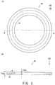
- FIG. 2 shows the configuration of the gasket 5.
- (A) of FIG. 2 is a plan view of the gasket 5, and
- (B) of FIG. 2 is a cross-sectional view of the gasket 5 of (A) of FIG. 2 taken along line B-B.
- the gasket 5 is solid.
- solid refers to the case where a product has no hollow portion; specifically, for example, the product is not produced by bending a plate so that a hollow portion is provided in the interior of the product.
- the gasket 5 contains copper (Cu) as a main component, and also contains nickel (Ni) in an amount of 0.1 wt.% or more. Since strength, elasticity, and stress relaxation resistance are improved through addition of Ni to Cu, loosening of the gasket can be suppressed. The reason for this will be described hereinbelow with reference to experimental examples.
- the term "main component” refers to a component which is contained in an amount of 50 wt.% or more.
- stress relaxation resistance refers to resistance to a decrease in stress. The lower the percent stress relaxation, the better the stress relaxation resistance.
- the gasket 5 has a maximum thickness Tmax of 0.4 mm in the axial direction OD.
- Tmax the maximum thickness of the gasket 5
- the gas-tightness of the gasket 5 can be secured. The reason for this will be described hereinbelow with reference to experimental examples.
- the gasket 5 has a minimum thickness Tmin of 0.2 mm or more in the axial direction OD.
- the gasket 5 has a Vickers hardness (hereinafter may be referred to simply as "hardness") of 80 HV.
- hardness 80 HV.
- the hardness of the gasket 5 is 30 HV to 150 HV, loosening of the gasket can be suppressed while gas-tightness is secured. The reason for this will be described hereinbelow with reference to experimental examples.
- annealing is carried out under the following conditions: annealing temperature: 300 to 600°C, annealing time: 30 to 90 minutes.
- the gasket 5 further contains phosphorus (P) in an amount of 0.01 wt.% to 0.50 wt.%.
- P phosphorus
- the gasket 5 exhibits improved stress relaxation resistance. Therefore, loosening of the gasket 5 can be further suppressed. The reason for this will be described hereinbelow with reference to experimental examples.
- the gasket 5 further contains tin (Sn) in an amount of 0.3 wt.% to 11.0 wt.%.
- Sn tin
- Sn forms a solid solution in a copper matrix, and thus the gasket 5 exhibits improved strength and elasticity. Therefore, screwing accuracy upon repeated screwing/unscrewing can be improved. The reason for this will be described hereinbelow with reference to experimental examples.
- the gasket 5 contains the three elements: nickel, phosphorus, and tin in a total amount of 2.0 wt.% or less. In this case, since a reduction in thermal conductivity of the gasket 5 can be suppressed, loosening of the gasket 5 can be further suppressed.
- five protrusions 5g are provided on an inner peripheral portion of the gasket 5. These protrusions 5g are formed through partial deformation of the inner peripheral portion by pressing the gasket 5 by means of a jig in a direction opposite the axial direction OD after fitting of the gasket 5 onto the spark plug 100. In the case where these protrusions 5g are formed, when the spark plug 100 is not attached to the engine head, removal of the gasket 5 from the spark plug 100 can be prevented.
- the thickness, hardness, and material of the solid gasket 5 are appropriately determined, loosening of the gasket can be suppressed while gas-tightness is secured.
- the area S of a surface of the gasket 5 which is in contact with the metallic shell 50 hereinafter the area S may be referred to as "contact area S"
- contact area S the area S of a surface of the gasket 5 which is in contact with the metallic shell 50
- FIG. 3 shows the configuration of a gasket 5b according to a second embodiment.
- the gasket 5b has the same configuration as the gasket of the first embodiment shown in FIG. 2 , except that an annular groove 5x is provided in place of the protrusions 5g.
- the groove 5x is formed through deformation of the gasket 5b by pressing it by means of a jig in a direction opposite the axial direction OD after fitting of the gasket 5b onto the spark plug 100.
- the groove 5x is formed, the inner diameter of the gasket 5b is reduced. Therefore, when the spark plug 100 is not attached to the engine head, removal of the gasket 5b from the spark plug 100 can be prevented.
- this configuration realizes securement of gas-tightness and suppression of loosening of the gasket.
- Experimental examples C1. Experimental example on gas-tightness: A plurality of gasket samples having different maximum thicknesses Tmax and hardnesses and being formed of different materials were employed for examining the effects of these factors on gas-tightness.
- a spark plug including a gasket was attached to an aluminum bush (i.e., a simulation of an engine block); the spark plug was subjected to repeated heating-cooling cycles (heating to 200°C and cooling to 20°C every 30 minutes); and the spark plug was subjected to alternate longitudinal vibration (eight hours) and lateral vibration (eight hours) (total vibration time: 32 hours) under the following ISO vibration conditions.
- the temperature of a portion (surface) of the aluminum bush with which the gasket was in contact was adjusted to 200°C, and compressed air was applied to the spark plug from the ignition portion side for a specific period of time.
- the amount of air leakage from the gasket was 10 cc or less
- gas-tightness was evaluated as being highest, and rating "A” was assigned.
- rating "B” was assigned.
- rating "C” was assigned.
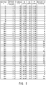
- FIG. 4 shows, in a table form, evaluation results of gas-tightness.
- five samples were prepared under the same conditions, and, among the five samples, the sample showing the poorest results was employed for evaluation. The same shall apply to the below-described other experimental examples.
- rating "A" or "B” is assigned in the case where the maximum thickness Tmax of a gasket is 0.4 mm or more.
- the reason for this is as follows. In the case of a gasket having a maximum thickness Tmax of 0.4 mm or more, even when the gasket is compressed, sufficient stroke is secured. Therefore, the shape difference between the gasket and the engine block can be compensated, and gas-tightness is improved.
- rating "A" is assigned in the case where the maximum thickness Tmax of a gasket is 0.4 mm or more and the hardness thereof is 150 HV or less.
- the reason for this is as follows. In the case of a gasket having a hardness of 150 HV or less, the surface of the gasket can be appropriately deformed. Therefore, the shape difference between the gasket and the engine block is compensated, and adhesion is improved at the contact surface between the gasket and the engine block or between the gasket and the spark plug, whereby gas-tightness is improved.
- the maximum thickness Tmax and hardness of a gasket are preferably 0.4 mm or more and 150 HV or less, respectively.
- the indenter force during the Vickers hardness test was 1.96 N.
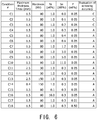
- FIG. 5 shows, in a table form, evaluation results of loosening.
- rating "AA” or “A” is assigned in the case where the hardness of a gasket is 30 HV or more and the Ni content of the gasket is 0.1 wt.% or more.
- the reason for this is as follows. When Ni is added to Cu, the resultant Cu alloy exhibits improved stress relaxation resistance, and thus loosening of the gasket can be suppressed. When the hardness is 30 HV or more, since plastic deformation of the gasket can be prevented, loosening of the gasket can be suppressed.
- rating "AA" is assigned in the case where the P content of a gasket is 0.01 wt.% or more.
- the reason for this is as follows. When P is incorporated, a segregation product containing Ni and P is produced, and thus stress relaxation resistance can be further improved.
- the hardness of the gasket is 30 HV or more and the Ni content of the gasket is 0.1 wt.% or more, particularly preferably, the P content of the gasket is 0.01 wt.% or more.
- the total amount of Ni, Sn, and P incorporated is preferably 2 wt.% or less.
- rating "AA” or “A” is assigned in the case where the hardness of a gasket is 30 HV or more and the Ni content of the gasket is 0.1 wt.% to 10.0 wt.%, and that rating "AA” is assigned in the case where the P content of a gasket is 0.01 wt.% to 0.50 wt.%.
- rating "A” i.e., highest evaluation
- rating "C” i.e., low evaluation
- FIG. 6 shows, in a table form, evaluation results of screwing accuracy.
- rating "A" was assigned. The reason for this is as follows.
- Sn is incorporated in an amount of 0.3 wt.% or more, the resultant Cu alloy exhibits increased elasticity. Therefore, even when the spark plug is repeatedly screwed and unscrewed, the spark plug exhibits improved positioning accuracy.
- the Sn content of a gasket is preferably adjusted to 0.3 wt.% or more.
- rating "A" is assigned in the case where the Sn content of a gasket is 0.3 wt.% to 11.0 wt.%.
- Experimental example on loosening 2 In the present experimental example, there was examined the relationship between the contact area S of the gasket 5 and loosening of the gasket after completion of the durability test. Specifically, two types of gaskets having different compositions were provided, and a plurality of samples for each type having different contact areas S were prepared. In the present experimental example, 30 samples for each type were prepared under the same conditions.
- FIG. 7 shows, in a table form, experimental results of loosening.
- FIG. 8 shows, in a graph form, the relationship between the contact area S of the gasket 5 and the number of samples exhibiting suppressed loosening.
- samples of type 1 loosening is likely to occur in association with a decrease in contact area S, whereas in samples of type 2 (i.e., samples containing Ni), loosening does not occur even when the contact area S of the gasket 5 is small.
Landscapes
- Engineering & Computer Science (AREA)
- General Engineering & Computer Science (AREA)
- Mechanical Engineering (AREA)
- Chemical & Material Sciences (AREA)
- Combustion & Propulsion (AREA)
- Spark Plugs (AREA)
- Ignition Installations For Internal Combustion Engines (AREA)
Description
- The present invention relates to a spark plug.
- In recent years, increasing demand has arisen for improvement of the fuel consumption of engines for automobiles. Since an important point for fuel consumption improvement is the attachment accuracy of a spark plug to an engine, demand has arisen for improvement of the attachment accuracy. Requirements for attachment accuracy improvement include, for example, the amount of protrusion of a spark plug into a combustion chamber, and the direction of an outer electrode (ground electrode) of a spark plug.
- Hitherto, a gasket having a hollow structure has been replaced by a gasket formed of an annular plate material for the purpose of improving the attachment accuracy of a spark plug. A known technique regarding a gasket formed of a plate material is disclosed in, for example,
Patent Document 1. However, this technique is insufficiently devised in terms of securement of gas-tightness and suppression of loosening.EP 1 707 936 A1JP H06 283249 A -
- Patent Document 1:
JP2008-210681A - Patent Document 2:
JP-H11-351393A - Patent Document 3:
JP4272682B - Patent Document 4:
EP1850432-A2 - The present invention has been accomplished for solving the aforementioned conventional problems at least partially, and an object of the present invention is to provide a technique which realizes securement of gas-tightness and suppression of loosening of a gasket.
- The present invention has been accomplished for solving the aforementioned problems at least partially, and may be carried out in the following modes or application examples.
- A spark plug comprising a tubular metallic shell extending in an axial direction, and an annular gasket provided around the metallic shell, the spark plug being characterized in that the gasket is solid, contains copper as a main component, and contains nickel in an amount of 0.10 wt.% or more; the gasket has a maximum thickness of 0.4 mm or more in the axial direction; and the gasket has a Vickers hardness of 30 HV to 150 HV.
- A spark plug according to application example 1, wherein the gasket further contains phosphorus in an amount of 0.01 wt.% to 0.50 wt.%.
- A spark plug according to application example 1 or 2, wherein the gasket further contains tin in an amount of 0.30 wt.% to 11.00 wt.%.
- A spark plug according to any one of application examples 1 to 3, wherein the gasket contains one or more elements selected from among nickel, phosphorus, and tin, the one or more elements including at least nickel; and the total amount of the one or more elements is 2.00 wt.% or less.
- A spark plug according to any one of application examples 1 to 4, wherein the gasket has a surface which is in contact with the metallic shell and which has an area of 111 mm2 or less.
- The present invention may be carried out in various modes; for example, in a mode of a spark plug production method or a spark plug production apparatus.
- According to the configuration of application example 1, since the gasket has an appropriate hardness and an appropriate thickness, gas-tightness can be secured. In addition, since the gasket contains an appropriate amount of nickel, the gasket exhibits improved stress relaxation resistance, and loosening of the gasket can be suppressed.
- According to the configuration of application example 2, since the gasket exhibits improved stress relaxation resistance, loosening of the gasket can be further suppressed.
- According to the configuration of application example 3, the gasket exhibits increased elasticity. Therefore, even when the spark plug is temporarily removed from an engine head and then screwed thereinto again, the spark plug exhibits enhanced screwing accuracy.
- According to the configuration of application example 4, since a reduction in thermal conductivity of the gasket can be suppressed, loosening of the gasket can be further suppressed.
- In the spark plug having the configuration according to application example 5, loosening of the gasket can be effectively suppressed.
-
-
FIG. 1 is a partial cross-sectional view of a spark plug according to one embodiment of the present invention. -
FIG. 2 shows the configuration of a gasket. -
FIG. 3 shows the configuration of a gasket according to a second embodiment. -
FIG. 4 shows, in a table form, evaluation results of gas-tightness. -
FIG. 5 shows, in a table form, evaluation results of loosening. -
FIG. 6 shows, in a table form, evaluation results of screwing accuracy. -
FIG. 7 shows, in a table form, experimental results of loosening. -
FIG. 8 shows, in a graph form, the relationship between the contact area S of agasket 5 and the number of samples exhibiting suppressed loosening. - A mode of the present invention will next be described with reference to embodiments, which will be shown in the following order: A. first embodiment; B. second embodiment; C. experimental examples; C1. experimental example on gas-tightness; C2. experimental example 1 on loosening; C3. experimental example on screwing accuracy; C4. experimental example 2 on loosening; and D. modifications.
- A. First embodiment:
FIG. 1 is a partial cross-sectional view of aspark plug 100 according to one embodiment of the present invention. InFIG. 1 , the axial direction OD of thespark plug 100 is referred to as the vertical direction. In the following description, the lower side of thespark plug 100 is referred to as the forward end side of thespark plug 100, and the upper side as the rear end side. - The
spark plug 100 includes aninsulator 10, ametallic shell 50, acenter electrode 20, aground electrode 30, and aterminal shell 40. Thecenter electrode 20 is held in theinsulator 10 so as to extend in the axial direction OD. Theinsulator 10, which serves as an insulating material, is inserted in themetallic shell 50. Theterminal shell 40 is provided at the rear end of theinsulator 10. - The
insulator 10, which has a tubular shape, is formed through firing of alumina or the like, and has, in the center thereof, anaxial hole 12 extending in the axial direction OD. Theinsulator 10 has, in the vicinity of its center in the axial direction OD, aflange portion 19 having the largest outer diameter. A rear-end-side body portion 18 is provided on the rear end side (upper side ofFIG. 1 ) with respect to theflange portion 19. A forward-end-side body portion 17 having an outer diameter smaller than that of the rear-end-side body portion 18 is provided on the forward end side (lower side ofFIG. 1 ) with respect to theflange portion 19. Furthermore, anelongated leg portion 13 having an outer diameter smaller than that of the forward-end-side body portion 17 is provided at the forward end of the forward-end-side body portion 17. When thespark plug 100 is attached to anengine head 200 of an internal combustion engine, theelongated leg portion 13, whose diameter decreases toward the forward end, is exposed to a combustion chamber of the internal combustion engine. Asupport portion 15 is provided between theelongated leg portion 13 and the forward-end-side body portion 17. - The
metallic shell 50, which has a circular tubular shape, is formed of low-carbon steel material, and is employed for fixing thespark plug 100 to theengine head 200 of the internal combustion engine. Themetallic shell 50 holds therein theinsulator 10, and a portion of the insulator 10 (including a part of the rear-end-side body portion 18 and the elongated leg portion 13) is surrounded by themetallic shell 50. - The
metallic shell 50 has atool engagement portion 51 and a threadedattachment portion 52. Thetool engagement portion 51 is fitted with a spark plug wrench (not illustrated). The threadedattachment portion 52 of themetallic shell 50 has a thread and is screwed into a threadedattachment hole 201 of theengine head 200 provided at the upper portion of the internal combustion engine. In the present embodiment, the threadedattachment portion 52 has a thread diameter of M12. - A flange-
like sealing portion 54 is provided between thetool engagement portion 51 and the threadedattachment portion 52 of themetallic shell 50. Anannular gasket 5 is fitted to the outer periphery of themetallic shell 50; more specifically, thegasket 5 is fitted to ascrew neck 59 provided between the threadedattachment portion 52 and the sealingportion 54. By means of thegasket 5, sealing is achieved between thespark plug 100 and theengine head 200, and gas-tightness of the engine is secured via the threadedattachment hole 201. Thegasket 5 will be described below in detail. - A
thin crimp portion 53 is provided on the rear end side of themetallic shell 50 with respect to thetool engagement portion 51. As in the case of thecrimp portion 53, a thin buckling portion 58 is provided between the sealingportion 54 and thetool engagement portion 51.Annular ring members tool engagement portion 51 to the crimp portion 53) and the outer wall of the rear-end-side body portion 18 of theinsulator 10. Furthermore, powder oftalc 9 is charged between thering members crimp portion 53 is bent radially inward; i.e., themetallic shell 50 is crimped radially inward, theinsulator 10 is pressed toward the forward end of themetallic shell 50 via thering members talc 9. Thus, thesupport portion 15 of theinsulator 10 is supported by a stepped portion 56 provided on the inner wall of themetallic shell 50, and themetallic shell 50 and theinsulator 10 are integrated together. With this configuration, gas-tightness between themetallic shell 50 and theinsulator 10 is maintained by means of an annular plate packing 8 provided between thesupport portion 15 of theinsulator 10 and the stepped portion 56 of themetallic shell 50, whereby leakage of combustion gas is prevented. The plate packing 8 is formed of, for example, a material having high thermal conductivity, such as copper or aluminum. When the plate packing 8 has high thermal conductivity, since heat from theinsulator 10 is effectively transferred to the stepped portion 56 of themetallic shell 50, thespark plug 100 exhibits favorable heat dissipation, and thus heat resistance can be improved. The buckling portion 58 is formed so as to bend and deform outward in association with an increase in compression force during crimping, whereby the gas-tightness in themetallic shell 50 is enhanced by increased compression stroke of thetalc 9. A clearance CL of specific dimensions is provided between a forward-end-side portion of the metallic shell 50 (with respect to the stepped portion 56) and theinsulator 10. - The
center electrode 20, which is a rod-like electrode, has a structure including an electrode matrix 21, and acore member 25 embedded in the electrode matrix 21. The electrode matrix 21 is formed of nickel or an alloy containing nickel as a main component, such as Inconel (trade name) 600 or 601. Thecore member 25 is formed of a material having thermal conductivity higher than that of the electrode matrix 21; i.e., thecore member 25 is formed of copper or an alloy containing copper as a main component. Generally, thecenter electrode 20 is produced by charging thecore member 25 into the electrode matrix 21 having a bottomed tubular shape, and elongating the matrix 21 (from the bottom side) through extrusion molding. Thecore member 25 has, at its body portion, a generally constant outer diameter, and has a decreased diameter portion on the forward end side. Thecenter electrode 20 extends in theaxial hole 12 toward the rear end side, and is electrically connected to theterminal shell 40 via a sealingbody 4 and aceramic resistor 3. Theterminal shell 40 is connected to a high-voltage cable (not illustrated) via a plug cap (not illustrated), whereby high voltage is applied to the spark plug. - A
forward end portion 22 of thecenter electrode 20 projects from aforward end portion 11 of theinsulator 10. Acenter electrode tip 90 is bonded to the end of theforward end portion 22 of thecenter electrode 20. Thecenter electrode tip 90 extends in the axial direction OD and has a generally circular columnar shape. Thecenter electrode tip 90 is formed of a high-melting-point noble metal for improving the spark erosion resistance thereof. Thecenter electrode tip 90 is formed of, for example, iridium (Ir), or an Ir alloy containing Ir as a main component and also containing one element or two or more elements selected from among platinum (Pt), rhodium (Rh), ruthenium (Ru), palladium (Pd), and rhenium (Re). - The
ground electrode 30 is formed of a metal having high corrosion resistance; for example, a nickel alloy such as Inconel (trade name) 600 or 601. Aproximal portion 32 of theground electrode 30 is bonded to aforward end portion 57 of themetallic shell 50 through welding. Theground electrode 30 is bent such that adistal end portion 33 of theground electrode 30 faces thecenter electrode tip 90. - A
ground electrode tip 95 is bonded to thedistal end portion 33 of theground electrode 30. Theground electrode tip 95 faces thecenter electrode tip 90, and a spark discharge gap G is provided between theground electrode tip 95 and thecenter electrode tip 90. Theground electrode tip 95 may be formed of a material similar to that employed for thecenter electrode tip 90. -
FIG. 2 shows the configuration of thegasket 5. (A) ofFIG. 2 is a plan view of thegasket 5, and (B) ofFIG. 2 is a cross-sectional view of thegasket 5 of (A) ofFIG. 2 taken along line B-B. - As shown in (B) of
FIG. 2 , thegasket 5 is solid. As used herein, the term "solid" refers to the case where a product has no hollow portion; specifically, for example, the product is not produced by bending a plate so that a hollow portion is provided in the interior of the product. - The
gasket 5 contains copper (Cu) as a main component, and also contains nickel (Ni) in an amount of 0.1 wt.% or more. Since strength, elasticity, and stress relaxation resistance are improved through addition of Ni to Cu, loosening of the gasket can be suppressed. The reason for this will be described hereinbelow with reference to experimental examples. As used herein, the term "main component" refers to a component which is contained in an amount of 50 wt.% or more. As used herein, the term "stress relaxation resistance" refers to resistance to a decrease in stress. The lower the percent stress relaxation, the better the stress relaxation resistance. - In the present embodiment, the
gasket 5 has a maximum thickness Tmax of 0.4 mm in the axial direction OD. When the maximum thickness Tmax of thegasket 5 is 0.4 mm or more, the gas-tightness of thegasket 5 can be secured. The reason for this will be described hereinbelow with reference to experimental examples. Preferably, thegasket 5 has a minimum thickness Tmin of 0.2 mm or more in the axial direction OD. - In the present embodiment, the
gasket 5 has a Vickers hardness (hereinafter may be referred to simply as "hardness") of 80 HV. When the hardness of thegasket 5 is 30 HV to 150 HV, loosening of the gasket can be suppressed while gas-tightness is secured. The reason for this will be described hereinbelow with reference to experimental examples. - In order to adjust the hardness of the
gasket 5 to 30 HV to 150 HV, annealing is carried out under the following conditions: annealing temperature: 300 to 600°C, annealing time: 30 to 90 minutes. - In the present embodiment, the
gasket 5 further contains phosphorus (P) in an amount of 0.01 wt.% to 0.50 wt.%. When P is incorporated, a segregation product containing Ni and P is produced, and thus thegasket 5 exhibits improved stress relaxation resistance. Therefore, loosening of thegasket 5 can be further suppressed. The reason for this will be described hereinbelow with reference to experimental examples. - In the present embodiment, the
gasket 5 further contains tin (Sn) in an amount of 0.3 wt.% to 11.0 wt.%. When Sn is incorporated, Sn forms a solid solution in a copper matrix, and thus thegasket 5 exhibits improved strength and elasticity. Therefore, screwing accuracy upon repeated screwing/unscrewing can be improved. The reason for this will be described hereinbelow with reference to experimental examples. - In the present embodiment, the
gasket 5 contains the three elements: nickel, phosphorus, and tin in a total amount of 2.0 wt.% or less. In this case, since a reduction in thermal conductivity of thegasket 5 can be suppressed, loosening of thegasket 5 can be further suppressed. - In the present embodiment, five
protrusions 5g are provided on an inner peripheral portion of thegasket 5. Theseprotrusions 5g are formed through partial deformation of the inner peripheral portion by pressing thegasket 5 by means of a jig in a direction opposite the axial direction OD after fitting of thegasket 5 onto thespark plug 100. In the case where theseprotrusions 5g are formed, when thespark plug 100 is not attached to the engine head, removal of thegasket 5 from thespark plug 100 can be prevented. - Thus, in the first embodiment, since the thickness, hardness, and material of the
solid gasket 5 are appropriately determined, loosening of the gasket can be suppressed while gas-tightness is secured. Particularly, even when the area S of a surface of thegasket 5 which is in contact with the metallic shell 50 (hereinafter the area S may be referred to as "contact area S") is small; specifically, even when the contact area S is 111 mm2 or less, loosening of the gasket can be effectively suppressed. The reason for determination of a specific value of the contact area S will be described hereinbelow. The significant figures of element content shown in the present specification and drawings are two decimal places. - B. Second embodiment:
FIG. 3 shows the configuration of agasket 5b according to a second embodiment. Thegasket 5b has the same configuration as the gasket of the first embodiment shown inFIG. 2 , except that anannular groove 5x is provided in place of theprotrusions 5g. Thegroove 5x is formed through deformation of thegasket 5b by pressing it by means of a jig in a direction opposite the axial direction OD after fitting of thegasket 5b onto thespark plug 100. When thegroove 5x is formed, the inner diameter of thegasket 5b is reduced. Therefore, when thespark plug 100 is not attached to the engine head, removal of thegasket 5b from thespark plug 100 can be prevented. As in the case of the first embodiment, this configuration realizes securement of gas-tightness and suppression of loosening of the gasket. - C. Experimental examples: C1. Experimental example on gas-tightness: A plurality of gasket samples having different maximum thicknesses Tmax and hardnesses and being formed of different materials were employed for examining the effects of these factors on gas-tightness. In this experimental example, a spark plug including a gasket was attached to an aluminum bush (i.e., a simulation of an engine block); the spark plug was subjected to repeated heating-cooling cycles (heating to 200°C and cooling to 20°C every 30 minutes); and the spark plug was subjected to alternate longitudinal vibration (eight hours) and lateral vibration (eight hours) (total vibration time: 32 hours) under the following ISO vibration conditions. ISO vibration conditions (ISO 11565 (2006)): frequency: 50 to 500 Hz, sweep rate: 1 octave/min, acceleration: 30 G. Hereinafter, the aforementioned test performed on the spark plug (i.e., repeated heating and cooling, and vibration) may be referred to as the "durability test."
- After completion of the durability test, the temperature of a portion (surface) of the aluminum bush with which the gasket was in contact was adjusted to 200°C, and compressed air was applied to the spark plug from the ignition portion side for a specific period of time. When the amount of air leakage from the gasket was 10 cc or less, gas-tightness was evaluated as being highest, and rating "A" was assigned. When the amount of air leakage from the gasket was more than 10 cc and 20 cc or less, gas-tightness was evaluated as being second highest, and rating "B" was assigned. When the amount of air leakage from the gasket was more than 20 cc, gas-tightness was evaluated as being lowest, and rating "C" was assigned.
-
FIG. 4 shows, in a table form, evaluation results of gas-tightness. In this experimental example, five samples were prepared under the same conditions, and, among the five samples, the sample showing the poorest results was employed for evaluation. The same shall apply to the below-described other experimental examples. - As is clear from
FIG. 4 , rating "A" or "B" is assigned in the case where the maximum thickness Tmax of a gasket is 0.4 mm or more. The reason for this is as follows. In the case of a gasket having a maximum thickness Tmax of 0.4 mm or more, even when the gasket is compressed, sufficient stroke is secured. Therefore, the shape difference between the gasket and the engine block can be compensated, and gas-tightness is improved. - As is also clear from
FIG. 4 , rating "A" is assigned in the case where the maximum thickness Tmax of a gasket is 0.4 mm or more and the hardness thereof is 150 HV or less. The reason for this is as follows. In the case of a gasket having a hardness of 150 HV or less, the surface of the gasket can be appropriately deformed. Therefore, the shape difference between the gasket and the engine block is compensated, and adhesion is improved at the contact surface between the gasket and the engine block or between the gasket and the spark plug, whereby gas-tightness is improved. Thus, the maximum thickness Tmax and hardness of a gasket are preferably 0.4 mm or more and 150 HV or less, respectively. - The indenter force during the Vickers hardness test was 1.96 N.
- C2. Experimental example on loosening 1: A plurality of gasket samples having different maximum thicknesses Tmax and hardnesses and being formed of different materials were employed for examining the effects of these factors on loosening after completion of the durability test. In this experimental example, the spark plug was removed from the aluminum bush after completion of the aforementioned durability test. When the torque after removal of the spark plug was 50% or more of that during attachment thereof, rating "AA" (i.e., highest evaluation) was assigned. When the torque after removal of the spark plug was 30% or more and less than 50% of that during attachment thereof, rating "A" (i.e., second highest evaluation) was assigned. When the torque after removal of the spark plug was less than 30% of that during attachment thereof, rating "C" (i.e., low evaluation) was assigned.
-
FIG. 5 shows, in a table form, evaluation results of loosening. As is clear fromFIG. 5 , rating "AA" or "A" is assigned in the case where the hardness of a gasket is 30 HV or more and the Ni content of the gasket is 0.1 wt.% or more. The reason for this is as follows. When Ni is added to Cu, the resultant Cu alloy exhibits improved stress relaxation resistance, and thus loosening of the gasket can be suppressed. When the hardness is 30 HV or more, since plastic deformation of the gasket can be prevented, loosening of the gasket can be suppressed. - As is also clear from
FIG. 5 , rating "AA" is assigned in the case where the P content of a gasket is 0.01 wt.% or more. The reason for this is as follows. When P is incorporated, a segregation product containing Ni and P is produced, and thus stress relaxation resistance can be further improved. - Thus, in order to suppress loosening of a gasket, preferably, the hardness of the gasket is 30 HV or more and the Ni content of the gasket is 0.1 wt.% or more, particularly preferably, the P content of the gasket is 0.01 wt.% or more.
- Meanwhile, when the amount of Ni, Sn, or P incorporated is large, the resultant Cu alloy exhibits low thermal conductivity. When a spark plug including a gasket having low thermal conductivity is employed for a long period of time, the temperature of the gasket is elevated, and plastic deformation of the gasket proceeds, which causes loosening of the gasket. Therefore, in order to suppress loosening of the gasket, the total amount of Ni, Sn, and P incorporated is preferably 2 wt.% or less.
- In the present experimental example, it was found that rating "AA" or "A" is assigned in the case where the hardness of a gasket is 30 HV or more and the Ni content of the gasket is 0.1 wt.% to 10.0 wt.%, and that rating "AA" is assigned in the case where the P content of a gasket is 0.01 wt.% to 0.50 wt.%.
- C3. Experimental example on screwing accuracy: A plurality of gasket samples having different maximum thicknesses Tmax and hardnesses and being formed of different materials were employed for examining the effects of these factors on screwing accuracy after repeated screwing/unscrewing cycles. In this experimental example, firstly, the aforementioned durability test was performed. Then, there were performed five screwing/unscrewing cycles, each including removal of the spark plug from the aluminum bush, and reattachment of the spark plug to the aluminum bush at the same screwing torque as the first one.
- When the difference between the screwing angle at the first cycle and that at the fifth cycle was +5° or less, rating "A" (i.e., highest evaluation) was assigned, whereas when the difference between the screwing angle at the first cycle and that at the fifth cycle was more than +5°, rating "C" (i.e., low evaluation) was assigned.
-
FIG. 6 shows, in a table form, evaluation results of screwing accuracy. As is clear fromFIG. 6 , when the Sn content of a gasket was 0.3 wt.% or more, rating "A" was assigned. The reason for this is as follows. When Sn is incorporated in an amount of 0.3 wt.% or more, the resultant Cu alloy exhibits increased elasticity. Therefore, even when the spark plug is repeatedly screwed and unscrewed, the spark plug exhibits improved positioning accuracy. Thus, in order to improve positioning accuracy after repeated screwing/unscrewing cycles, the Sn content of a gasket is preferably adjusted to 0.3 wt.% or more. In the present experiment example, it was found that rating "A" is assigned in the case where the Sn content of a gasket is 0.3 wt.% to 11.0 wt.%. - C4. Experimental example on loosening 2: In the present experimental example, there was examined the relationship between the contact area S of the
gasket 5 and loosening of the gasket after completion of the durability test. Specifically, two types of gaskets having different compositions were provided, and a plurality of samples for each type having different contact areas S were prepared. In the present experimental example, 30 samples for each type were prepared under the same conditions. - Each of the thus-prepared samples was subjected to the aforementioned durability test, and the sample (spark plug) was removed from the aluminum bush after completion of the durability test. When the torque after removal of a sample was less than 50% of that during attachment of the sample, it was regarded that loosening occurred in the sample. Thus, the number of samples in which loosening occurred was recorded. Details of the two types of gaskets are as follows. The contact area S was adjusted by changing the outer diameter of a gasket.
-
- Type 1: composition: copper content is 99.90 wt.% or more (containing no Ni), maximum thickness Tmax: 1.5 mm, hardness: 60 HV, inner diameter: 9.5 mm.
- Type 2: composition: copper content is 99 wt.% and Ni content is 0.1 wt.%, maximum thickness Tmax: 1.5 mm, hardness: 60 HV, inner diameter: 9.5 mm.
-
FIG. 7 shows, in a table form, experimental results of loosening.FIG. 8 shows, in a graph form, the relationship between the contact area S of thegasket 5 and the number of samples exhibiting suppressed loosening. As is clear fromFIG. 7 , in samples oftype 1, loosening is likely to occur in association with a decrease in contact area S, whereas in samples of type 2 (i.e., samples containing Ni), loosening does not occur even when the contact area S of thegasket 5 is small. - As is clear from the number of samples exhibiting suppression of loosening through incorporation of nickel (see
FIG. 8 ), the smaller the contact area S of thegasket 5, the greater the number of samples exhibiting improvement. Specifically, the number of samples exhibiting improvement considerably increases when the contact area S of thegasket 5 is 111 mm2 or less. Thus, these data indicate that a remarkable loosening suppression effect is obtained when the contact area S of thegasket 5 is 111 mm2 or less. - D. Modifications: The present invention is not limited to the aforementioned examples and embodiments, and various other embodiments may be implemented without departing from the scope of the invention. For example, the below-described modifications may be carried out.
- D1. Modification 1: In each of the gaskets according to the aforementioned embodiments, the
protrusion 5g or thegroove 5x is provided. However, these may be omitted. - D2. Modification 2: In each of the spark plugs according to the aforementioned embodiments, the direction of discharge corresponds to the axial direction OD. However, the present invention may be applied to a spark plug in which the direction of discharge is perpendicular to the axial direction OD; i.e., a so-called lateral-discharge-type spark plug.
- D3. Modification 3: In each of the spark plugs according to the aforementioned embodiments, the
center electrode tip 90 and theground electrode tip 95 are provided. However, one or both of these tips may be omitted. -
- 3: ceramic resistor
- 4: sealing body
- 5: gasket
- 5b: gasket
- 5g: protrusion
- 5x: groove
- 6: ring member
- 8: plate packing
- 9: talc
- 10: insulator
- 11: forward end portion
- 12: axial hole
- 13: elongated leg portion
- 15: support portion
- 17: forward-end-side body portion
- 18: rear-end-side body portion
- 19: flange portion
- 20: center electrode
- 21: electrode matrix
- 22: forward end portion
- 25: core member
- 30: ground electrode
- 32: proximal portion
- 33: distal end portion
- 40: terminal shell
- 50: metallic shell
- 51: tool engagement portion
- 52: threaded attachment portion
- 53: crimp portion
- 54: sealing portion
- 56: stepped portion
- 57: forward end portion
- 58: buckling portion
- 59: screw neck
- 90: center electrode tip
- 95: ground electrode tip
- 100: spark plug
- 200: engine head
- 201: threaded attachment hole
- G: spark discharge gap
- OD: axial direction
- CL: clearance
Claims (7)
- A spark plug comprising:a tubular metallic shell (50) extending in an axial direction; andan annular gasket (5, 5b) provided around the metallic shell (50), wherein :the gasket (5, 5b) is solid and contains copper as a main component and nickel in an amount of 0.10 wt.% or more;the gasket (5, 5b) has a maximum thickness of 0.4 mm or more in the axial direction; andthe gasket (5, 5b) has a Vickers hardness of 30 HV to 150 HV,
the spark plug being characterized in that the gasket (5, 5b) has a surface which is in contact with the metallic shell and which has an area of 111 mm2 or less. - A spark plug according to claim 1, wherein the gasket (5, 5b) further contains phosphorus in an amount of 0.01 wt.% to 0.50 wt.%.
- A spark plug according to claim 1 or 2, wherein the gasket (5, 5b) further contains tin in an amount of 0.30 wt.% to 11.00 wt.%.
- A spark plug according to any one of claims 1 to 3, wherein the gasket (5, 5b) contains one or more elements selected from among nickel, phosphorus, and tin, the one or more elements including at least nickel; and the total amount of the one or more elements is 2.00 wt.% or less.
- A spark plug according to claim 1, wherein the gasket (5, 5b) further contains phosphorus and tin, wherein the total amount of nickel, phosphorus and tin is 2.00 wt.% or less.
- A spark plug according to any one of claims 1 to 5, wherein the gasket (5) includes protrusions (5g) formed on an inner peripheral portion of the gasket (5).
- A spark plug according to any one of claims 1 to 5, wherein the gasket (5b) includes an annular groove (5x).
Applications Claiming Priority (2)
| Application Number | Priority Date | Filing Date | Title |
|---|---|---|---|
| JP2011152782A JP2013020790A (en) | 2011-07-11 | 2011-07-11 | Spark plug |
| PCT/JP2012/002640 WO2013008371A1 (en) | 2011-07-11 | 2012-04-17 | Spark plug |
Publications (3)
| Publication Number | Publication Date |
|---|---|
| EP2733797A1 EP2733797A1 (en) | 2014-05-21 |
| EP2733797A4 EP2733797A4 (en) | 2015-03-04 |
| EP2733797B1 true EP2733797B1 (en) | 2018-08-29 |
Family
ID=47505683
Family Applications (1)
| Application Number | Title | Priority Date | Filing Date |
|---|---|---|---|
| EP12810850.3A Active EP2733797B1 (en) | 2011-07-11 | 2012-04-17 | Spark plug |
Country Status (5)
| Country | Link |
|---|---|
| US (1) | US9194494B2 (en) |
| EP (1) | EP2733797B1 (en) |
| JP (1) | JP2013020790A (en) |
| CN (1) | CN103797670B (en) |
| WO (1) | WO2013008371A1 (en) |
Families Citing this family (11)
| Publication number | Priority date | Publication date | Assignee | Title |
|---|---|---|---|---|
| JP5867327B2 (en) * | 2012-07-18 | 2016-02-24 | 株式会社デンソー | Spark plug mounting gasket and spark plug mounting structure |
| JP5973928B2 (en) * | 2013-02-07 | 2016-08-23 | 日本特殊陶業株式会社 | Spark plug and manufacturing method thereof |
| BR112015019485A2 (en) * | 2013-02-15 | 2017-07-18 | Ngk Spark Plug Co | spark plug |
| EP2983217B1 (en) | 2013-04-04 | 2018-10-31 | Toshiba Lighting & Technology Corporation | Lighting device |
| JP6565344B2 (en) * | 2015-06-02 | 2019-08-28 | 株式会社デンソー | Spark plug for internal combustion engine and method for manufacturing the same |
| CN106129813B (en) * | 2016-06-12 | 2018-09-07 | 株洲湘火炬火花塞有限责任公司 | A kind of spark plug seal washer locking forming method and seal washer |
| CN108123367A (en) * | 2016-11-29 | 2018-06-05 | 日本特殊陶业株式会社 | Spark plug |
| DE102017109844B4 (en) | 2017-05-08 | 2019-08-14 | Federal-Mogul Ignition Gmbh | A method of manufacturing a spark plug assembly and spark plug assembly |
| CN108006226A (en) * | 2017-12-21 | 2018-05-08 | 苏州锐德飞自动化设备有限公司 | A kind of locking antiskid compound gasket |
| JP6878359B2 (en) * | 2018-07-05 | 2021-05-26 | 日本特殊陶業株式会社 | Spark plug |
| JP6839218B2 (en) * | 2019-02-26 | 2021-03-03 | 日本特殊陶業株式会社 | How to make a spark plug |
Citations (1)
| Publication number | Priority date | Publication date | Assignee | Title |
|---|---|---|---|---|
| JPH06283249A (en) * | 1993-03-25 | 1994-10-07 | Ngk Spark Plug Co Ltd | Gasket for spark plug |
Family Cites Families (11)
| Publication number | Priority date | Publication date | Assignee | Title |
|---|---|---|---|---|
| US3254154A (en) | 1966-05-31 | Ceramic-to-metal seal for spark plugs | ||
| JPS54113690U (en) | 1978-01-27 | 1979-08-09 | ||
| JP4104211B2 (en) | 1998-06-10 | 2008-06-18 | 日本特殊陶業株式会社 | Gasket and threaded member having gasket |
| JP2001082609A (en) | 1999-09-09 | 2001-03-30 | Motoyama Eng Works Ltd | Seal gasket |
| US7004478B2 (en) | 2001-12-07 | 2006-02-28 | Perkinelmer Inc. | Shallow metallic s-seal |
| EP1476684A1 (en) | 2002-02-20 | 2004-11-17 | Garlock Sealing Technologies LLC | Metal seal and retainer |
| US7272970B2 (en) * | 2005-03-31 | 2007-09-25 | Ngk Spark Plug Co., Ltd. | Spark plug having combustion pressure detecting function |
| JP4530418B2 (en) * | 2005-03-31 | 2010-08-25 | 日本特殊陶業株式会社 | Spark plug with combustion pressure detection function |
| DE102006062737B4 (en) | 2006-04-28 | 2014-06-26 | Federal-Mogul Ignition Gmbh | Method for producing a spark plug |
| JP4272682B2 (en) | 2006-10-30 | 2009-06-03 | 日本特殊陶業株式会社 | Spark plug for internal combustion engine and method for manufacturing the same |
| JP4296202B2 (en) | 2007-02-27 | 2009-07-15 | 日本特殊陶業株式会社 | Spark plug manufacturing method and spark plug manufactured by the manufacturing method |
-
2011
- 2011-07-11 JP JP2011152782A patent/JP2013020790A/en active Pending
-
2012
- 2012-04-17 EP EP12810850.3A patent/EP2733797B1/en active Active
- 2012-04-17 CN CN201280034543.4A patent/CN103797670B/en active Active
- 2012-04-17 US US14/131,410 patent/US9194494B2/en active Active
- 2012-04-17 WO PCT/JP2012/002640 patent/WO2013008371A1/en active Application Filing
Patent Citations (1)
| Publication number | Priority date | Publication date | Assignee | Title |
|---|---|---|---|---|
| JPH06283249A (en) * | 1993-03-25 | 1994-10-07 | Ngk Spark Plug Co Ltd | Gasket for spark plug |
Also Published As
| Publication number | Publication date |
|---|---|
| CN103797670A (en) | 2014-05-14 |
| US9194494B2 (en) | 2015-11-24 |
| US20140145405A1 (en) | 2014-05-29 |
| EP2733797A4 (en) | 2015-03-04 |
| EP2733797A1 (en) | 2014-05-21 |
| CN103797670B (en) | 2016-11-16 |
| JP2013020790A (en) | 2013-01-31 |
| WO2013008371A1 (en) | 2013-01-17 |
Similar Documents
| Publication | Publication Date | Title |
|---|---|---|
| EP2733797B1 (en) | Spark plug | |
| US8664843B2 (en) | Spark plug | |
| US8129891B2 (en) | Spark plug | |
| EP2216861B1 (en) | Spark plug | |
| EP3621165B1 (en) | Spark plug | |
| US8723406B2 (en) | Spark plug | |
| US9276383B2 (en) | Spark plug, and production method therefor | |
| EP3739701B1 (en) | Spark plug | |
| EP2894735A2 (en) | Spark plug | |
| JP2013149623A (en) | Spark plug | |
| JP5028299B2 (en) | Spark plug | |
| JP5683409B2 (en) | Spark plug and method of manufacturing spark plug | |
| US9660423B2 (en) | Spark plug having an electrode structure that effectively suppresses flashover | |
| JP5513466B2 (en) | Manufacturing method of spark plug | |
| EP2634872B1 (en) | Spark plug | |
| JP5721680B2 (en) | Spark plug | |
| JP6653785B2 (en) | Spark plug | |
| JP2005166291A (en) | Spark plug | |
| JP2024065803A (en) | Spark plug and manufacturing method | |
| CN114930659A (en) | Spark plug | |
| EP3076502A1 (en) | Ignition plug |
Legal Events
| Date | Code | Title | Description |
|---|---|---|---|
| PUAI | Public reference made under article 153(3) epc to a published international application that has entered the european phase |
Free format text: ORIGINAL CODE: 0009012 |
|
| 17P | Request for examination filed |
Effective date: 20140110 |
|
| AK | Designated contracting states |
Kind code of ref document: A1 Designated state(s): AL AT BE BG CH CY CZ DE DK EE ES FI FR GB GR HR HU IE IS IT LI LT LU LV MC MK MT NL NO PL PT RO RS SE SI SK SM TR |
|
| DAX | Request for extension of the european patent (deleted) | ||
| A4 | Supplementary search report drawn up and despatched |
Effective date: 20150129 |
|
| RIC1 | Information provided on ipc code assigned before grant |
Ipc: H01T 13/08 20060101AFI20150123BHEP Ipc: F16J 15/08 20060101ALI20150123BHEP Ipc: F02P 13/00 20060101ALI20150123BHEP |
|
| STAA | Information on the status of an ep patent application or granted ep patent |
Free format text: STATUS: EXAMINATION IS IN PROGRESS |
|
| 17Q | First examination report despatched |
Effective date: 20170131 |
|
| RAP1 | Party data changed (applicant data changed or rights of an application transferred) |
Owner name: NGK SPARK PLUG CO., LTD. |
|
| GRAP | Despatch of communication of intention to grant a patent |
Free format text: ORIGINAL CODE: EPIDOSNIGR1 |
|
| STAA | Information on the status of an ep patent application or granted ep patent |
Free format text: STATUS: GRANT OF PATENT IS INTENDED |
|
| RIC1 | Information provided on ipc code assigned before grant |
Ipc: F16J 15/06 20060101ALI20180323BHEP Ipc: H01T 13/08 20060101AFI20180323BHEP Ipc: F16J 15/08 20060101ALI20180323BHEP Ipc: F02P 13/00 20060101ALI20180323BHEP |
|
| INTG | Intention to grant announced |
Effective date: 20180425 |
|
| GRAS | Grant fee paid |
Free format text: ORIGINAL CODE: EPIDOSNIGR3 |
|
| GRAA | (expected) grant |
Free format text: ORIGINAL CODE: 0009210 |
|
| STAA | Information on the status of an ep patent application or granted ep patent |
Free format text: STATUS: THE PATENT HAS BEEN GRANTED |
|
| AK | Designated contracting states |
Kind code of ref document: B1 Designated state(s): AL AT BE BG CH CY CZ DE DK EE ES FI FR GB GR HR HU IE IS IT LI LT LU LV MC MK MT NL NO PL PT RO RS SE SI SK SM TR |
|
| REG | Reference to a national code |
Ref country code: GB Ref legal event code: FG4D |
|
| REG | Reference to a national code |
Ref country code: CH Ref legal event code: EP |
|
| REG | Reference to a national code |
Ref country code: AT Ref legal event code: REF Ref document number: 1036274 Country of ref document: AT Kind code of ref document: T Effective date: 20180915 |
|
| REG | Reference to a national code |
Ref country code: IE Ref legal event code: FG4D |
|
| REG | Reference to a national code |
Ref country code: DE Ref legal event code: R096 Ref document number: 602012050470 Country of ref document: DE |
|
| REG | Reference to a national code |
Ref country code: NL Ref legal event code: MP Effective date: 20180829 |
|
| REG | Reference to a national code |
Ref country code: LT Ref legal event code: MG4D |
|
| PG25 | Lapsed in a contracting state [announced via postgrant information from national office to epo] |
Ref country code: LT Free format text: LAPSE BECAUSE OF FAILURE TO SUBMIT A TRANSLATION OF THE DESCRIPTION OR TO PAY THE FEE WITHIN THE PRESCRIBED TIME-LIMIT Effective date: 20180829 Ref country code: SE Free format text: LAPSE BECAUSE OF FAILURE TO SUBMIT A TRANSLATION OF THE DESCRIPTION OR TO PAY THE FEE WITHIN THE PRESCRIBED TIME-LIMIT Effective date: 20180829 Ref country code: BG Free format text: LAPSE BECAUSE OF FAILURE TO SUBMIT A TRANSLATION OF THE DESCRIPTION OR TO PAY THE FEE WITHIN THE PRESCRIBED TIME-LIMIT Effective date: 20181129 Ref country code: NL Free format text: LAPSE BECAUSE OF FAILURE TO SUBMIT A TRANSLATION OF THE DESCRIPTION OR TO PAY THE FEE WITHIN THE PRESCRIBED TIME-LIMIT Effective date: 20180829 Ref country code: GR Free format text: LAPSE BECAUSE OF FAILURE TO SUBMIT A TRANSLATION OF THE DESCRIPTION OR TO PAY THE FEE WITHIN THE PRESCRIBED TIME-LIMIT Effective date: 20181130 Ref country code: NO Free format text: LAPSE BECAUSE OF FAILURE TO SUBMIT A TRANSLATION OF THE DESCRIPTION OR TO PAY THE FEE WITHIN THE PRESCRIBED TIME-LIMIT Effective date: 20181129 Ref country code: FI Free format text: LAPSE BECAUSE OF FAILURE TO SUBMIT A TRANSLATION OF THE DESCRIPTION OR TO PAY THE FEE WITHIN THE PRESCRIBED TIME-LIMIT Effective date: 20180829 Ref country code: IS Free format text: LAPSE BECAUSE OF FAILURE TO SUBMIT A TRANSLATION OF THE DESCRIPTION OR TO PAY THE FEE WITHIN THE PRESCRIBED TIME-LIMIT Effective date: 20181229 Ref country code: RS Free format text: LAPSE BECAUSE OF FAILURE TO SUBMIT A TRANSLATION OF THE DESCRIPTION OR TO PAY THE FEE WITHIN THE PRESCRIBED TIME-LIMIT Effective date: 20180829 |
|
| REG | Reference to a national code |
Ref country code: AT Ref legal event code: MK05 Ref document number: 1036274 Country of ref document: AT Kind code of ref document: T Effective date: 20180829 |
|
| PG25 | Lapsed in a contracting state [announced via postgrant information from national office to epo] |
Ref country code: HR Free format text: LAPSE BECAUSE OF FAILURE TO SUBMIT A TRANSLATION OF THE DESCRIPTION OR TO PAY THE FEE WITHIN THE PRESCRIBED TIME-LIMIT Effective date: 20180829 Ref country code: LV Free format text: LAPSE BECAUSE OF FAILURE TO SUBMIT A TRANSLATION OF THE DESCRIPTION OR TO PAY THE FEE WITHIN THE PRESCRIBED TIME-LIMIT Effective date: 20180829 Ref country code: AL Free format text: LAPSE BECAUSE OF FAILURE TO SUBMIT A TRANSLATION OF THE DESCRIPTION OR TO PAY THE FEE WITHIN THE PRESCRIBED TIME-LIMIT Effective date: 20180829 |
|
| PG25 | Lapsed in a contracting state [announced via postgrant information from national office to epo] |
Ref country code: CZ Free format text: LAPSE BECAUSE OF FAILURE TO SUBMIT A TRANSLATION OF THE DESCRIPTION OR TO PAY THE FEE WITHIN THE PRESCRIBED TIME-LIMIT Effective date: 20180829 Ref country code: RO Free format text: LAPSE BECAUSE OF FAILURE TO SUBMIT A TRANSLATION OF THE DESCRIPTION OR TO PAY THE FEE WITHIN THE PRESCRIBED TIME-LIMIT Effective date: 20180829 Ref country code: EE Free format text: LAPSE BECAUSE OF FAILURE TO SUBMIT A TRANSLATION OF THE DESCRIPTION OR TO PAY THE FEE WITHIN THE PRESCRIBED TIME-LIMIT Effective date: 20180829 Ref country code: IT Free format text: LAPSE BECAUSE OF FAILURE TO SUBMIT A TRANSLATION OF THE DESCRIPTION OR TO PAY THE FEE WITHIN THE PRESCRIBED TIME-LIMIT Effective date: 20180829 Ref country code: AT Free format text: LAPSE BECAUSE OF FAILURE TO SUBMIT A TRANSLATION OF THE DESCRIPTION OR TO PAY THE FEE WITHIN THE PRESCRIBED TIME-LIMIT Effective date: 20180829 Ref country code: ES Free format text: LAPSE BECAUSE OF FAILURE TO SUBMIT A TRANSLATION OF THE DESCRIPTION OR TO PAY THE FEE WITHIN THE PRESCRIBED TIME-LIMIT Effective date: 20180829 Ref country code: PL Free format text: LAPSE BECAUSE OF FAILURE TO SUBMIT A TRANSLATION OF THE DESCRIPTION OR TO PAY THE FEE WITHIN THE PRESCRIBED TIME-LIMIT Effective date: 20180829 |
|
| PG25 | Lapsed in a contracting state [announced via postgrant information from national office to epo] |
Ref country code: SK Free format text: LAPSE BECAUSE OF FAILURE TO SUBMIT A TRANSLATION OF THE DESCRIPTION OR TO PAY THE FEE WITHIN THE PRESCRIBED TIME-LIMIT Effective date: 20180829 Ref country code: DK Free format text: LAPSE BECAUSE OF FAILURE TO SUBMIT A TRANSLATION OF THE DESCRIPTION OR TO PAY THE FEE WITHIN THE PRESCRIBED TIME-LIMIT Effective date: 20180829 Ref country code: SM Free format text: LAPSE BECAUSE OF FAILURE TO SUBMIT A TRANSLATION OF THE DESCRIPTION OR TO PAY THE FEE WITHIN THE PRESCRIBED TIME-LIMIT Effective date: 20180829 |
|
| REG | Reference to a national code |
Ref country code: DE Ref legal event code: R097 Ref document number: 602012050470 Country of ref document: DE |
|
| PLBE | No opposition filed within time limit |
Free format text: ORIGINAL CODE: 0009261 |
|
| STAA | Information on the status of an ep patent application or granted ep patent |
Free format text: STATUS: NO OPPOSITION FILED WITHIN TIME LIMIT |
|
| 26N | No opposition filed |
Effective date: 20190531 |
|
| PG25 | Lapsed in a contracting state [announced via postgrant information from national office to epo] |
Ref country code: SI Free format text: LAPSE BECAUSE OF FAILURE TO SUBMIT A TRANSLATION OF THE DESCRIPTION OR TO PAY THE FEE WITHIN THE PRESCRIBED TIME-LIMIT Effective date: 20180829 |
|
| REG | Reference to a national code |
Ref country code: CH Ref legal event code: PL |
|
| REG | Reference to a national code |
Ref country code: BE Ref legal event code: MM Effective date: 20190430 |
|
| GBPC | Gb: european patent ceased through non-payment of renewal fee |
Effective date: 20190417 |
|
| PG25 | Lapsed in a contracting state [announced via postgrant information from national office to epo] |
Ref country code: LU Free format text: LAPSE BECAUSE OF NON-PAYMENT OF DUE FEES Effective date: 20190417 Ref country code: MC Free format text: LAPSE BECAUSE OF FAILURE TO SUBMIT A TRANSLATION OF THE DESCRIPTION OR TO PAY THE FEE WITHIN THE PRESCRIBED TIME-LIMIT Effective date: 20180829 |
|
| PG25 | Lapsed in a contracting state [announced via postgrant information from national office to epo] |
Ref country code: GB Free format text: LAPSE BECAUSE OF NON-PAYMENT OF DUE FEES Effective date: 20190417 Ref country code: CH Free format text: LAPSE BECAUSE OF NON-PAYMENT OF DUE FEES Effective date: 20190430 Ref country code: LI Free format text: LAPSE BECAUSE OF NON-PAYMENT OF DUE FEES Effective date: 20190430 |
|
| PG25 | Lapsed in a contracting state [announced via postgrant information from national office to epo] |
Ref country code: BE Free format text: LAPSE BECAUSE OF NON-PAYMENT OF DUE FEES Effective date: 20190430 |
|
| PG25 | Lapsed in a contracting state [announced via postgrant information from national office to epo] |
Ref country code: TR Free format text: LAPSE BECAUSE OF FAILURE TO SUBMIT A TRANSLATION OF THE DESCRIPTION OR TO PAY THE FEE WITHIN THE PRESCRIBED TIME-LIMIT Effective date: 20180829 |
|
| PG25 | Lapsed in a contracting state [announced via postgrant information from national office to epo] |
Ref country code: IE Free format text: LAPSE BECAUSE OF NON-PAYMENT OF DUE FEES Effective date: 20190417 |
|
| PG25 | Lapsed in a contracting state [announced via postgrant information from national office to epo] |
Ref country code: PT Free format text: LAPSE BECAUSE OF FAILURE TO SUBMIT A TRANSLATION OF THE DESCRIPTION OR TO PAY THE FEE WITHIN THE PRESCRIBED TIME-LIMIT Effective date: 20181229 |
|
| PGFP | Annual fee paid to national office [announced via postgrant information from national office to epo] |
Ref country code: FR Payment date: 20200312 Year of fee payment: 9 |
|
| PG25 | Lapsed in a contracting state [announced via postgrant information from national office to epo] |
Ref country code: CY Free format text: LAPSE BECAUSE OF FAILURE TO SUBMIT A TRANSLATION OF THE DESCRIPTION OR TO PAY THE FEE WITHIN THE PRESCRIBED TIME-LIMIT Effective date: 20180829 |
|
| PG25 | Lapsed in a contracting state [announced via postgrant information from national office to epo] |
Ref country code: MT Free format text: LAPSE BECAUSE OF FAILURE TO SUBMIT A TRANSLATION OF THE DESCRIPTION OR TO PAY THE FEE WITHIN THE PRESCRIBED TIME-LIMIT Effective date: 20180829 Ref country code: HU Free format text: LAPSE BECAUSE OF FAILURE TO SUBMIT A TRANSLATION OF THE DESCRIPTION OR TO PAY THE FEE WITHIN THE PRESCRIBED TIME-LIMIT; INVALID AB INITIO Effective date: 20120417 |
|
| PG25 | Lapsed in a contracting state [announced via postgrant information from national office to epo] |
Ref country code: FR Free format text: LAPSE BECAUSE OF NON-PAYMENT OF DUE FEES Effective date: 20210430 |
|
| PG25 | Lapsed in a contracting state [announced via postgrant information from national office to epo] |
Ref country code: MK Free format text: LAPSE BECAUSE OF FAILURE TO SUBMIT A TRANSLATION OF THE DESCRIPTION OR TO PAY THE FEE WITHIN THE PRESCRIBED TIME-LIMIT Effective date: 20180829 |
|
| P01 | Opt-out of the competence of the unified patent court (upc) registered |
Effective date: 20230512 |
|
| PGFP | Annual fee paid to national office [announced via postgrant information from national office to epo] |
Ref country code: DE Payment date: 20230228 Year of fee payment: 12 |
|
| REG | Reference to a national code |
Ref country code: DE Ref legal event code: R081 Ref document number: 602012050470 Country of ref document: DE Owner name: NITERRA CO., LTD., NAGOYA-SHI, JP Free format text: FORMER OWNER: NGK SPARK PLUG CO., LTD., NAGOYA-SHI, AICHI, JP |