EP2733544A1 - Developer storing container, developer storing unit, process cartridge, and electrophotographic image formation device - Google Patents
Developer storing container, developer storing unit, process cartridge, and electrophotographic image formation device Download PDFInfo
- Publication number
- EP2733544A1 EP2733544A1 EP12811330.5A EP12811330A EP2733544A1 EP 2733544 A1 EP2733544 A1 EP 2733544A1 EP 12811330 A EP12811330 A EP 12811330A EP 2733544 A1 EP2733544 A1 EP 2733544A1
- Authority
- EP
- European Patent Office
- Prior art keywords
- developer
- openings
- unsealing
- sealing member
- developer accommodating
- Prior art date
- Legal status (The legal status is an assumption and is not a legal conclusion. Google has not performed a legal analysis and makes no representation as to the accuracy of the status listed.)
- Granted
Links
Images



















Classifications
-
- G—PHYSICS
- G03—PHOTOGRAPHY; CINEMATOGRAPHY; ANALOGOUS TECHNIQUES USING WAVES OTHER THAN OPTICAL WAVES; ELECTROGRAPHY; HOLOGRAPHY
- G03G—ELECTROGRAPHY; ELECTROPHOTOGRAPHY; MAGNETOGRAPHY
- G03G15/00—Apparatus for electrographic processes using a charge pattern
- G03G15/06—Apparatus for electrographic processes using a charge pattern for developing
- G03G15/08—Apparatus for electrographic processes using a charge pattern for developing using a solid developer, e.g. powder developer
- G03G15/0822—Arrangements for preparing, mixing, supplying or dispensing developer
- G03G15/0865—Arrangements for supplying new developer
- G03G15/0874—Arrangements for supplying new developer non-rigid containers, e.g. foldable cartridges, bags
-
- G—PHYSICS
- G03—PHOTOGRAPHY; CINEMATOGRAPHY; ANALOGOUS TECHNIQUES USING WAVES OTHER THAN OPTICAL WAVES; ELECTROGRAPHY; HOLOGRAPHY
- G03G—ELECTROGRAPHY; ELECTROPHOTOGRAPHY; MAGNETOGRAPHY
- G03G15/00—Apparatus for electrographic processes using a charge pattern
- G03G15/06—Apparatus for electrographic processes using a charge pattern for developing
- G03G15/08—Apparatus for electrographic processes using a charge pattern for developing using a solid developer, e.g. powder developer
-
- G—PHYSICS
- G03—PHOTOGRAPHY; CINEMATOGRAPHY; ANALOGOUS TECHNIQUES USING WAVES OTHER THAN OPTICAL WAVES; ELECTROGRAPHY; HOLOGRAPHY
- G03G—ELECTROGRAPHY; ELECTROPHOTOGRAPHY; MAGNETOGRAPHY
- G03G15/00—Apparatus for electrographic processes using a charge pattern
- G03G15/06—Apparatus for electrographic processes using a charge pattern for developing
- G03G15/08—Apparatus for electrographic processes using a charge pattern for developing using a solid developer, e.g. powder developer
- G03G15/0822—Arrangements for preparing, mixing, supplying or dispensing developer
- G03G15/0877—Arrangements for metering and dispensing developer from a developer cartridge into the development unit
- G03G15/0881—Sealing of developer cartridges
- G03G15/0882—Sealing of developer cartridges by a peelable sealing film
-
- G—PHYSICS
- G03—PHOTOGRAPHY; CINEMATOGRAPHY; ANALOGOUS TECHNIQUES USING WAVES OTHER THAN OPTICAL WAVES; ELECTROGRAPHY; HOLOGRAPHY
- G03G—ELECTROGRAPHY; ELECTROPHOTOGRAPHY; MAGNETOGRAPHY
- G03G21/00—Arrangements not provided for by groups G03G13/00 - G03G19/00, e.g. cleaning, elimination of residual charge
- G03G21/16—Mechanical means for facilitating the maintenance of the apparatus, e.g. modular arrangements
- G03G21/18—Mechanical means for facilitating the maintenance of the apparatus, e.g. modular arrangements using a processing cartridge, whereby the process cartridge comprises at least two image processing means in a single unit
-
- G—PHYSICS
- G03—PHOTOGRAPHY; CINEMATOGRAPHY; ANALOGOUS TECHNIQUES USING WAVES OTHER THAN OPTICAL WAVES; ELECTROGRAPHY; HOLOGRAPHY
- G03G—ELECTROGRAPHY; ELECTROPHOTOGRAPHY; MAGNETOGRAPHY
- G03G2215/00—Apparatus for electrophotographic processes
- G03G2215/06—Developing structures, details
- G03G2215/066—Toner cartridge or other attachable and detachable container for supplying developer material to replace the used material
- G03G2215/0682—Bag-type non-rigid container
Definitions
- the sealing member 19 has a free end portion in one end side thereof with respect to the unsealing direction E, and at the free end portion, the portion-to-be-engaged 19b to be engaged with the unsealing member for moving the sealing member is provided. With the portion-to-be-engaged 19b, the unsealing member for moving the sealing member so as to expose the openings is engaged.
- the unsealing member may also be configured to automatically perform the unsealing by receiving drive (driving force) from the image forming apparatus main assembly B. Or, the unsealing member may also be configured to perform the unsealing by being held and moved by the user.
- the unsealing member 20 is a rotation shaft provided in the frame, and the sealing member 19 engaged with the unsealing member 20 is pulled, so that the developer accommodating container 26 accommodating the developer is unsealed.
- the following arrangement relation is required between the first bonding portion 22b and the fixing portion 18c.
- the unsealing member 20 pulls the sealing member 19 in the arrow D direction.
- the fixing portion 18c is provided in an upstream side of the openings 35a. For that reason, a force is applied to the fixing portion 18c in the arrow H direction.
- the long single opening 16a forms the plurality of openings 35a by the connecting members 16f, so that it also becomes possible to strengthen only the connecting members 16f.
- the urging sheet 21b fixed to the unsealing member 20, for urging the developer bag 16 is rotated, so that the urging sheet 21b is wound about the unsealing member 20 by the developer bag 16 as shown in Figure 9 .
- the urging sheet 21b has elasticity and therefore is likely to be restored to an original shape, thus urging the developer bag 16 in an arrow J direction.
- the developer bag 16 is urged by the urging sheet 21b and is pressed against the second frame 18 via the toner, so that the entire developer bag 16 is deformed. Further, the developer bag 16 is urged by the urging sheet 21b to be decreased in its inside volume.
- the unsealing member 20 is further rotated, so that the urging sheet 21b is separated from the developer bag 16.
- the developer bag 16 has flexibility and therefore is likely to be restored to the state before the urging by the weight of the developer (arrow K).
- the urging sheet 21b is rotated and urges the developer bag 16 toward the second frame 18 as shown in Figure 16 , so that the developer bag 16 is deformed to move the developer at a position other than the neighborhood of the openings 35a, and the developer is discharged from the openings 35a.
- the openings 35a are disposed at the molded portion 34a, but also the molded portion 34a is flexible similarly as in Embodiment 1, so that the force relationship is the same as that in Embodiment 1. Therefore, also in Embodiment 2, the plurality of connecting portions 35b bridge the first bonding portion 22a and the second bonding portion 22b with respect to the direction E in which the unsealing advances. For that reason, when the unsealing at the first bonding portion 22a is ended and the unsealing at the second bonding portion 22b is effected, a force for peeling the sealing member 19 from the developer accommodating member 34 can be transmitted. For that reason, the unsealing also at the bonding portion 22b becomes possible.
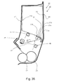
- FIGs 35 and 36 an example in the case where an urging member 21, an unsealing member 20 and a stirring member 41 are separate members, respectively is shown.
- Figure 35 is a schematic sectional view before unsealing
- Figure 36 is a schematic sectional view after the unsealing.
- each of the urging member 21, the unsealing member 20 and the stirring member 41 is rotatably supported by the first frame 17, and is rotated by receiving drive (driving force) from the main assembly of the image forming apparatus B.
- the unsealing member 20 is rotated in an arrow C direction, so that the sealing member 19 is wound up to expose the openings 35a.
Landscapes
- Physics & Mathematics (AREA)
- General Physics & Mathematics (AREA)
- Engineering & Computer Science (AREA)
- Computer Vision & Pattern Recognition (AREA)
- Dry Development In Electrophotography (AREA)
- Electrophotography Configuration And Component (AREA)
- Bag Frames (AREA)
- Printers Or Recording Devices Using Electromagnetic And Radiation Means (AREA)
Abstract
Description
- The present invention relates to an image forming apparatus, and a developer accommodating container, a developer accommodating unit, a developing device and a cartridge which are to be used in the image forming apparatus.
- Here, the image forming apparatus forms an image on a recording material (medium) by using, e.g., an electrophotographic image forming process and may include, e.g., an electrophotographic copying machine, an electrophotographic printer (such as an LED printer or a laser beam printer), an electrophotographic facsimile machine, and the like.
- Further, the cartridge refers to a cartridge including at least a developing means and the developing device which are integrally constituted to be made detachably mountable to an image forming apparatus main assembly and a cartridge including the developing device and at least a photosensitive member unit including a photosensitive member which are integrally constituted to be made detachably mountable to the image forming apparatus main assembly.
- Further, the developer accommodating container and the developer accommodating unit are accommodated in the image forming apparatus or the cartridge. The developer accommodating container and the developer accommodating unit are at least provided with a flexible container for accommodating the developer.
- In a conventional electrophotographic image forming apparatus using the electrophotographic image forming process, a process cartridge type in which an electrophotographic photosensitive member and process means actable on the photosensitive member are integrally assembled into a cartridge and this cartridge is detachably mountable to a main assembly of the electrophotographic image forming apparatus is employed.
- In such a process cartridge, as shown in
Figure 52 , an opening provided to adeveloper accommodating frame 31 for accommodating the developer (toner, carrier, etc.) is sealed with a sealing member. Further, a type in which a bonding portion 33 of atoner seal 32 which is the sealing member is pulled and peeled during use, thus unsealing the opening to enable supply of the developer has been widely employed (Japanese Laid-Open Patent Application (JP-A)Hei 4-66980 - Further, against a problem such that the developer is scattered in the process cartridge in a developer filling step during manufacturing of the process cartridge, a constitution in which a deformable inner container is used has been devised (
JP-A Hei 4-69980 - However, as in
JP-A Hei 4-66980 - Therefore, an object of the present invention is, in a constitution different from the conventional constitution, to propose a developer accommodating unit using a flexible container and being excellent in an unsealing property.
- One of constitutions of the inventions according to the present invention is as follows:
- A developer accommodating container for accommodating a developer, the developer accommodating container comprising: a flexible container including an injection port for permitting entrance of the developer and a plurality of openings for permitting discharge of the developer; and a sealing member, mounted on the flexible container in a state in which the sealing member seals the plurality of openings, capable of exposing the plurality of openings by being moved, wherein the plurality of openings are provided at different positions with respect to a perpendicular direction to an unsealing direction in which exposure of the plurality of openings advances.
- According to the present invention, in the accommodating container using the flexible container for accommodating the developer, the developer accommodating container or the developer accommodating unit, an unsealing characteristic of the sealing member for sealing the flexible container openings can be improved.
-
-
Figure 1 is a principal sectional view of a process cartridge in an embodiment of the present invention. -
Figure 2 is a principal sectional view of an image forming apparatus in the embodiment of the present invention. -
Figure 3 is a perspective view from a cross section of a developer accommodating container including an unsealing member in the embodiment of the present invention. -
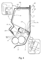
Figure 4 is a sectional view of a developer accommodating unit before unsealing in the embodiment of the present invention. -
Figure 5 is a sectional view of the developer accommodating unit immediately before the unsealing in the embodiment of the present invention. -
Figure 6 is a sectional view of the developer accommodating unit during unsealing in the embodiment of the present invention. -
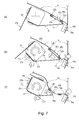
Figure 7 includes sectional views for illustrating a process of unsealing a discharging portion in the embodiment of the present invention. -
Figure 8 includes sectional views for illustrating the process of unsealing the discharging portion in the embodiment of the present invention. -
Figure 9 is a sectional view of the developer accommodating unit after the unsealing in the embodiment of the present invention. -
Figure 10 is an illustration of the developer accommodating container before unsealing in the embodiment of the present invention. -
Figure 11 is an illustration of the developer accommodating container during unsealing in the embodiment of the present invention. -
Figure 12 is a sectional view for illustrating the discharging portion in the embodiment of the present invention. -
Figure 13 includes illustrates of a hard-to-unseal developer accommodating container in which is not the embodiment of the present invention. -
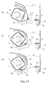
Figure 14 includes sectional views of the hard-to-unseal developer accommodating container which is not the embodiment of the present invention. -
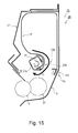
Figure 15 is a sectional view of a hard-to-unseal developer accommodating unit which is not the embodiment of the present invention. -
Figure 16 is a sectional view of the developer accommodating unit in the embodiment of the present invention. -
Figure 17 is a sectional view of the developer accommodating unit in the embodiment of the present invention. -
Figure 18 is a sectional view of a developer accommodating container in Second Embodiment of the present invention. -
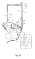
Figure 19 is a sectional view of a developer accommodating unit in Second Embodiment of the present invention. -
Figure 20 is an illustration of the developer accommodating container in the embodiment of the present invention. -
Figure 21 includes illustrations of the developer accommodating container in the embodiment of the present invention. -
Figure 22 includes illustrations of the developer accommodating container in the embodiment of the present invention. -
Figure 23 includes illustrations of a developer accommodating container which is not the embodiment of the present invention. -
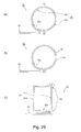
Figure 24 includes illustrations of the developer accommodating container in the embodiment of the present invention. -
Figure 25 includes illustrations of the developer accommodating unit in the embodiment of the present invention. -
Figure 26 includes illustrations of the developer accommodating unit in the embodiment of the present invention. -
Figure 27 includes illustrations of a fixing portion of the developer accommodating container in the embodiment of the present invention. -
Figure 28 includes illustrations of openings of the developer accommodating container in the embodiment of the present invention. -
Figure 29 includes sectional views of the developer accommodating container in the embodiment of the present invention. -
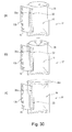
Figure 30 includes illustrations of developer accommodating containers in embodiments of the present invention. -
Figure 31 includes illustrations of the developer accommodating container including an unsealing member. -
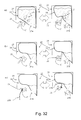
Figure 32 includes illustrations of the developer accommodating unit in the embodiment of the present invention. -
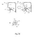
Figure 33 includes illustrations of the developer accommodating unit in the embodiment of the present invention. -
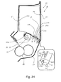
Figure 34 is an illustration of the developer accommodating unit in the embodiment of the present invention. -
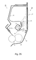
Figure 35 is a sectional view of a developer accommodating unit in an embodiment ofEmbodiment 3 of the present invention. -
Figure 36 is a sectional view of the developer accommodating unit in the embodiment ofEmbodiment 3 of the present invention. -
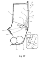
Figure 37 is a sectional view of a developer accommodating unit in an embodiment of Embodiment 4 of the present invention. -
Figure 38 is a sectional view of the developer accommodating unit in the embodiment of Embodiment 4 of the present invention. -
Figure 39 is a sectional view of the developer accommodating unit in the embodiment of Embodiment 4 of the present invention. -
Figure 40 is a sectional view of a developer accommodating unit in an embodiment of Embodiment 5 of the present invention. -
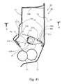
Figure 41 is a sectional view of a developer accommodating unit in an embodiment ofEmbodiment 7 of the present invention. -
Figure 42 is a schematic illustration of openings in the embodiment ofEmbodiment 7 of the present invention. -
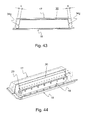
Figure 43 is a schematic illustration of the openings in the embodiment of theEmbodiment 7 of the present invention. -
Figure 44 is a schematic illustration of the openings in the embodiment ofEmbodiment 7 of the present invention. -
Figure 45 is a sectional view of the developer accommodating unit in the embodiment of Embodiment 5 of the present invention. -
Figure 46 is a sectional view of the developer accommodating unit in the embodiment of Embodiment 5 of the present invention. -
Figure 47 is a sectional view of a developer accommodating unit in an embodiment ofEmbodiment 6 of the present invention. -
Figure 48 is a sectional view of the developer accommodating unit in the embodiment ofEmbodiment 6 of the present invention. -
Figure 49 is a sectional view of the developer accommodating unit in the embodiment ofEmbodiment 6 of the present invention. -
Figure 50 includes schematic illustrations of drive transmission to an unsealing member in the embodiment of the present invention. -
Figure 51 includes sectional views of the developer accommodating unit in the embodiment ofEmbodiment 7 of the present invention. -
Figure 52 is a view for illustrating a conventional example. - In the following description, a developer accommodating container refers to at least a flexibility container and a sealing member for sealing an opening, provided to the flexible container, for permitting discharge of a developer. The developer accommodating container before the developer is accommodated therein is referred to as a
developer accommodating container 37 for accommodating the developer. The developer accommodating container which accommodates the developer and which is provided with an unsealing member for unsealing the sealing member is referred to as adeveloper accommodating container 30 including the unsealing member. The developer accommodating container which accommodates the developer and which is not provided with the sealing member is referred to as adeveloper accommodating container 26 accommodating the developer. - Incidentally, for simplification, these developer accommodating containers will be described as the
developer accommodating container 37, thedeveloper accommodating container 30 and thedeveloper accommodating container 26 by using different reference numerals. - A developer accommodating unit includes at least the developer accommodating container and a frame for accommodating the developer accommodating container.
-
Figure 1 illustrates a principal sectional view of a process cartridge including the developer accommodating unit to which the present invention is applicable, andFigure 2 illustrates a principal sectional view of an image forming apparatus to which the present invention is applicable. - The process cartridge includes an image bearing member and process means actable on the image bearing member. Here, as the process means, there are, e.g., a charging means for electrically charging a surface of the image bearing member, a developing device for forming an image on the image bearing member, and a cleaning means for removing a developer (containing toner, carrier, etc.) remaining on the image bearing member surface.
- The process cartridge A in this embodiment includes, as shown in
Figure 1 , includes a photosensitive (member)drum 11 as the image bearing member and includes, at a periphery of thephotosensitive drum 11, a chargingroller 12 as the charging means and acleaner unit 24 including acleaning blade 14, having elasticity, as the cleaning means. Further, the process cartridge A includes a developingdevice 38 including afirst frame 17 and asecond frame 18. The process cartridge A integrally includes thecleaner unit 24 and the developingdevice 38, and is constituted so as to be detachably mountable to an image forming apparatus main assembly B as shown inFigure 2 . The developingdevice 38 includes a developingroller 13 as the developing means, a developingblade 15, adeveloper supplying roller 23, and adeveloper accommodating container 26, for accommodating the developer, in which the developer is accommodated. The developingroller 13 and the developing blade are supported by thefirst frame 17. - The process cartridge A is mounted in the image forming apparatus main assembly B as shown in
Figure 2 and is used for image formation. In the image formation, a sheet S is fed by a feedingroller 7 from asheet cassette 6 mounted at a lower portion of the apparatus, and in synchronism with this sheet feeding, thephotosensitive drum 11 is selectively exposed to light by anexposure device 8 to form a latent image. The developer is supplied to the developing roller 13 (developer carrying member) by the sponge-likedeveloper supplying roller 23 and is carried in a thin layer on the surface of the developingroller 13. By applying a developing bias to the developingroller 13, the developer is supplied depending on the latent image and thus the latent image is developed into a developer image. This (developer) image is transferred onto the fed sheet S by bias voltage application to a transfer roller 9. The sheet S is conveyed to a fixingdevice 10 to be subjected to image fixing, and the sheet S is discharged by asheet discharging roller 1 to asheet discharge portion 3 at an upper portion of the apparatus. - Next, a structure of a
developer accommodating unit 25 will be described with reference toFigures 3 ,Figure 4 , (a) ofFigure 7 andFigure 20 . Here,Figure 3 is a perspective view of thedeveloper accommodating container 30 from cross section,Figure 4 is a sectional view of the developingdevice 38,Figure 7 is a detailed sectional view in the neighborhood of the dischargingportion 35 for permitting discharge of the developer from adeveloper bag 16 as a flexible container, andFigure 20 is a sectional view of thedeveloper accommodating container 26 from cross section. Incidentally, the sectional views are a plane passing through an unsealingmember 20,openings 35a and fixingportions member 20. - The
developer accommodating unit 25 is, as shown inFigure 4 , constituted from thedeveloper accommodating container 30, the developingroller 13, the developingblade 15, and thefirst frame 17 and thesecond frame 18 which support these members. A combination of the first frame and the second frame is a frame which accommodates thedeveloper accommodating container 30. - Incidentally, in this embodiment, the
developer accommodating unit 25 is the same as the developingdevice 38. This is because thedeveloper accommodating unit 25 includes the developingroller 13 and the developingblade 15. However, the developingroller 13 and the developingblade 15 may also be supported by a frame separately from thedeveloper accommodating unit 25 and thus may be separated from thedeveloper accommodating unit 25. In this case, the developingdevice 38 is constituted by thedeveloper accommodating unit 25, the developingroller 13 and the developing blade 15 (not shown). - The
developer accommodating container 30 including the unsealing member is constituted by an unsealingmember 20 and thedeveloper accommodating container 26 as shown inFigure 3 andFigure 4 . - The unsealing
member 20 includes an engagingportion 20b to be engaged with a sealingmember 19, and by engaging a portion-to-be-engaged 19b of thedeveloper accommodating container 26 with the engagingportion 20b, thedeveloper accommodating container 30 including the unsealing member is constituted. - As shown in (c) of
Figure 30 , thedeveloper accommodating container 26 is constituted from the developer, adeveloper bag 16 and the sealingmember 19. Here, the developer is powder. - The
developer bag 16 of thedeveloper accommodating container 26 is sealed with the sealingmember 19 at the plurality ofopenings 35a for permitting the discharge of the developer and includes abonding portion 39a which seals a filling opening (injection port) for permitting filling (entrance) of the developer. Thus, therespective openings 35a and the fillingopening 39 of thedeveloper accommodating container 26 in which the developer is accommodated are sealed and therefore the accommodated developer is not leaked out to the outside, so that thedeveloper accommodating container 26 can be treated as a single unit. Further, the sealingmember 19 includes holes as the portions-to-be-engaged 19b to be engaged with the unsealingmember 20, thus being engageable with the unsealingmember 20. - As shown in (a) of
Figure 30 , thedeveloper accommodating container 37 for accommodating the developer is constituted from thedeveloper bag 16 and the sealingmember 19 for sealing the plurality ofopenings 35a for permitting the discharge of the developer and for exposing theopenings 35a by being moved. Here, thedeveloper bag 16 of thedeveloper accommodating container 37 for accommodating the developer includes the fillingopening 39 for permitting the filling of the developer and theopenings 35a for permitting the discharge of the developer. - Here, in the
developer accommodating container 37 for accommodating the developer, the developer is not filled as yet, and thedeveloper accommodating container 37 is in a state in which the fillingopening 39 for permitting the filling of the developer is open. - Here, a relation between the
developer accommodating container 37 for accommodating the developer and thedeveloper accommodating container 26 in which the developer is accommodated will be described. - First, as shown in (a) of
Figure 30 , thedeveloper accommodating container 37 for accommodating the developer is not filled with the developer and is provided with the fillingopening 39 for permitting the filling of the developer. - Next, as shown in (b) of
Figure 30 , the developer is filled from the fillingopening 39, for permitting the filling of the developer, of thedeveloper accommodating container 37 for accommodating the developer. Further, by flexibility of thedeveloper bag 16, the fillingopening 39 for permitting the filling of the developer is deformable correspondingly to a filling device and thus the filling of the developer is facilitated without causing scattering of the developer. At the time of the filling, a known auger type filling device is used but another method having a similar function may also be used. - Then, as shown in (c) of
Figure 30 , the fillingopening 39 for permitting the filling of the developer is bonded and sealed. The bonding of thebonding portion 39a of the opening for permitting the filling of the developer is made by ultrasonic bonding in this embodiment but may also be made by other bonding methods using heat, a laser and the like. - Then, when the bonding of the
bonding portion 39a of the opening for permitting the filling is completed, the developer is filled, so that thedeveloper accommodating container 26 in which the developer is accommodated is provided. - Incidentally, a position and a size of the filling
opening 39 for permitting the filling may appropriately by disposed correspondingly to shapes and the like of the filling device of the developer and the process cartridge A. - By forming the developer-accommodated
developer accommodating container 26 in a bag shape, the developer can be treated as a unit. For that reason, a developer filling step can be separated from a main assembling step (manufacturing line) of the process cartridge A. By this, the developer is prevented from being scattered in the main assembling step (manufacturing line) of the process cartridge A, so that maintenance such as cleaning of the manufacturing line can be reduced. By the prevention of the scattering of the developer during the assembling step, it is possible to omit a cleaning step of the process cartridge A to be performed after the filling of the developer. - Further, also in the filling step of the
developer bag 16, thedeveloper bag 16 has flexibility, and the fillingopening 39 for permitting the filling is also soft and therefore can be easily sealed with less scattering. - Further, the
developer accommodating container 26 in which the developer is accommodated has flexibility and therefore can be assembled while following a shape of the frame. - Further, in the filling step, the
developer accommodating container 37 has flexibility and therefore deforms its cross section to increase its volume in which the developer can be filled, so that a filling amount can be increased during the filling. - Further, the
developer accommodating container 37 before the developer filling has flexibility and thus can be made small (thin), so that a storing space during storage before the filling can be made small compared with the frame which is a resinous structure. - As shown in
Figure 3 andFigure 4 , thedeveloper bag 16 accommodates the developer therein and has a bag-like shape which is deformable, and is provided with the plurality ofopenings 35a at the dischargingportion 35, for permitting the discharge of the accommodated developer. - Further, the
developer bag 16 includes developer bag fixing portions (portions-to-be-fixed) 16d and 16e fixed to thefirst frame 17 and thesecond frame 18. -
Figure 29 includes sectional views for illustrating thedeveloper accommodating container 26. As shown in (a) ofFigure 29 , thedeveloper bag 16 is constituted by bonding asheet 16u which includes the dischargingportion 35 and does not have air permeability and asheet 16s which has the air permeability and which is an air permeable portion to each other. - Here, a degree of the air permeability may appropriately be selected so that the developer is prevented from leaking out of the
developer bag 16 based on a balance with a size of the developer (particle size of powder) to be accommodated. - As a material for the air
permeable portion 16s, a nonwoven fabric or the like formed of polyethylene terephthalate (PET), polyethylene (PE), polypropylene (PP) or the like in a thickness of 0.03 - 0.15 mm is preferred. Further, even when the material for the airpermeable portion 16s is not the nonwoven fabric, a material having minute holes which are smaller than the powder such as the developer may also be used. - Further, with respect to arrangement of the air permeable portion, in this embodiment, as shown in
Figure 3 andFigure 29 , the airpermeable portion 16s is disposed over the entire region of thedeveloper bag 16 with respect to a longitudinal direction in thesecond frame 18 side. Incidentally, as shown in (b) ofFigure 29 , the airpermeable portion 16s may also constitute theentire developer bag 16. - Incidentally, as the material for the
developer bag 16 other than the airpermeable portion 16s, a material having flexibility so as to improve efficiency during the discharge of the developer described later may preferably be used. Further, the material for the airpermeable portion 16s may also have flexibility. - Thus, the reason why the air permeability is imparted to the
developer bag 16 is that thedeveloper bag 16 can meet states during manufacturing, during transportation until a user uses the cartridge A, and during storage. First, the reason for the state during the manufacturing is that thedeveloper bag 16 is made deformable and reducible in order to facilitate assembling of thedeveloper bag 16 with theframes developer bag 16 is not provided with the air permeability portion, the size thereof cannot be changed from that in a state in which thedeveloper bag 16 is filled with the developer (state in which the bag is closed) and therefore thedeveloper bag 16 is not readily deformed. For that reason, it takes time to assembling and steps are complicated. Therefore, when the air permeability is imparted to at least a part of thedeveloper bag 16, the size of thedeveloper bag 16 can be changed from that in the state in which thedeveloper bag 16 is filled with the developer and then is closed, thus facilitating the assembling. - Next, the reason for the states during the transportation and during the storage is that the
developer bag 16 can meet a change in different air pressure during the transportation and during the storage of the process cartridge A. The difference in air pressure between the inside and outside of thedeveloper bag 16 is generated in the case where thedeveloper bag 16 is in a lower air-pressure environment during the transportation or the like than during the manufacturing or in the case where thedeveloper bag 16 is stored at a higher temperature than during the manufacturing. For that reason, by expansion of thedeveloper bag 16, there is a fear that parts contacting thedeveloper bag 16 are deformed or broken. There is a need, for that purpose, to control the air pressure and the temperature during the transportation and during the storage, so that facilitates and a cost are needed. However, problems caused due to the difference in air pressure between the inside and outside of thedeveloper bag 16 can be solved by partly imparting the air permeability to thedeveloper bag 16. - Further, in the case where the nonwoven fabric is provided with the discharging
portion 35 and abonding portion 22 at a periphery of the dischargingportion 35, there is a fear that fibers of the nonwoven fabric fall out with peeling of the sealingmember 19 during unsealing and then enter the developer to adversely affect the image. For that reason, by providing the dischargingportion 35 to thesheet 16u different from thesheet 16s having the air permeability, the above-described falling-out of the fibers from the nonwoven fabric is prevented. - Further, a filling density can be increased by filling the developer while deaerating the
developer bag 16. - As shown in
Figure 3 andFigure 10 , thedeveloper bag 16 includes thedeveloper discharging portion 35 consisting of the plurality ofopenings 35a for permitting the discharge of the inside developer and the connectingportion 35b defining the plurality ofopenings 35a. Further, the dischargingportion 35 is continuously surrounded at its periphery by thebonding portion 22 to be unsealably bonded, so that the developer accommodated in thedeveloper bag 16 is sealed with the sealingmember 19. - The
bonding portion 22 has a rectangular shape surrounded by two lines extending in a long direction (direction F) and two lines extending in a short direction (direction E), and therefore thebonding portion 22 enables the sealing of the dischargingportion 35. - Here, of the two lines of the
bonding portion 22 welded with respect to the long direction (direction F), a bonding portion which is first unsealed is referred to as afirst bonding portion 22a and a bonding portion which is unsealed later is referred to as asecond bonding portion 22b. In this embodiment, in the case where thebonding portion 22 is viewed along the surface of the sealingmember 19, the bonding portion in a side closer to a fold(ed)-back portion 19d (or portion-to-be-engaged 19b) described later is thefirst bonding portion 22a. Further, the bonding portion opposing thefirst bonding portion 22a via the opening is thesecond bonding portion 22b. Further, a bonding portion with respect to a widthwise direction is a widthwise (short)bonding portion 22c. - In this embodiment, an unsealing direction is the direction E. The unsealing direction is defined as follows. In the case where the unsealing is effected by moving the sealing
member 19, of thefirst bonding portion 22a and thesecond bonding portion 22b opposing to each other via theopening 35a, thefirst bonding portion 22a is first unsealed (peeled). Thus, a direction directed from thefirst bonding portion 22a to be first unsealed toward thesecond bonding portion 22b is the unsealing direction E. - Incidentally, when the sealing
member 19 is unsealed (peeled) from thedeveloper bag 16 in the E direction, when viewed microscopically, the peeling progresses also in the arrow F direction in some cases due to the deformation of thedeveloper bag 16 by an unsealing force also in thefirst bonding portion 22a and thesecond bonding portion 22b. However, the unsealing direction in this embodiment does not refer to such a microscopic unsealing direction. - Next, arrangement of the
openings 35a will be described with reference toFigure 10 ,Figure 11 andFigure 30 . The movement direction of the sealing member 19 (the direction of the sealingmember 19 pulled by the unsealing member 20) for sealing theopenings 35a and for exposing theopenings 35a by being moved is D. By the movement of the sealingmember 19, the exposure of theopenings 35a progresses in the unsealing direction E. In the following, the movement direction of the sealingmember 19 is D. - The plurality of
openings 35a and the plurality of connectingportions 35b are disposed at different positions in the direction F perpendicular to the unsealing direction E. Further, the sealingmember 19 is configured to be wound up by rotating the unsealingmember 20 but the above-described direction F is the same direction as an axis (axial line) of the rotation shaft of the unsealingmember 20. - Here, the reason why the rotational axis direction of the developing
roller 13 and the arranged direction F of the plurality ofopenings 35a are made equal is that the developer is easily supplied, during the discharge thereof, to the developingroller 13 over the entire longitudinal direction without being localized. - Here, the plurality of
openings 35a are disposed at the different positions in the direction of F and therefore the dischargingportion 35 is long in the direction F and is short in the direction E. That is, with respect to the direction F, a distance from an end to another end of the plurality ofopenings 35a is longer than that with respect to the direction E. - Thus, the discharging
portion 35 where the plurality ofopenings 35a are disposed at the different positions in the direction F perpendicular to the unsealing direction E is long in the direction F and is short in the direction E, and therefore the distance required for the unsealing can be made shorter than that required for the unsealing in the long direction F and therefore a time required for the unsealing can also be made short. - Further, a constitution in which the sealing
member 19 for covering the dischargingportion 35 is wound up by the unsealingmember 20 is employed. The rotational axis direction of the unsealingmember 20 and the direction F substantially perpendicular to the unsealing direction E are made equal, so that winding distance and time of the sealingmember 19 can be shortened. - Each of the plurality of
openings 35a inEmbodiment 1 has a circular shape. When a discharging property is taken into consideration, an area of theopenings 35a may preferably be large. Further, the connectingportions 35b defining theopenings 35a may preferably be large (thick) in order to enhance the strength of thedeveloper bag 16. Therefore, the area of theopenings 35a and the area of the connectingportions 35b are required to achieve a balance in view of a material and a thickness of the dischargingportion 35 and a force relationship with peeling strength during the unsealing described later and may be appropriately selected. Further, the shape of theopenings 35a may also be, in addition to the circular shape, a polygonal shape such as a rectangular shape, an elongated circular shape as shown inFigure 18 in Embodiment 2 described later, and the like shape. - Incidentally, the arrangement of the
openings 35a may only be required to be disposed at the different positions with respect to the direction F perpendicular to the unsealing direction E, and even when theopenings 35a overlap with each other as shown in (c) ofFigure 28 , or do not overlap with each other as shown in (d) ofFigure 28 , there is an effect of the connectingportions 35b described later. - Further, the direction of the
openings 35a may preferably be such that the developer accommodated in thedeveloper bag 16 is easily discharged in an attitude during image formation. For that reason, in the attitude during image formation, theopenings 35a are disposed so as to be open downward with respect to the gravitational direction. Here, the downward opening of theopenings 35a with respect to the gravitational direction refers to that the direction of theopenings 35a has a downward component with respect to the gravitational direction. - As shown in
Figure 3 andFigure 4 , thedeveloper bag 16 is fixed inside thefirst frame 17 and thesecond frame 18 by the two fixingportions - First, as a first fixing portion, the
first fixing portion 16d of thedeveloper bag 16 where a force is received when the sealingmember 19 is unsealed from thedeveloper bag 16 as described later is provided. Thefirst fixing portion 16d is provided at a plurality of positions in parallel to the direction F in which the plurality ofopenings 35a are arranged. Incidentally, other than the arrangement at the plurality of positions, thefirst fixing portion 16d may also be a single fixing portion elongated in parallel to the direction F (not shown). - Further, the position of the
first fixing portion 16d is provided in the neighborhood of theopenings 35a. - Further, the
first fixing portion 16d of thedeveloper bag 16 is fixed to afirst fixing portion 18a of the frame. - The
first fixing portion 16d is a fixing portion necessary for the time of unsealing thedeveloper bag 16, and its action and arrangement will be described later in the description of the unsealing. - Further, as a second fixing portion, the
second fixing portion 16e for preventing movement of thedeveloper bag 16 downward or toward the developingroller 13 and thedeveloper supplying roller 23 is provided. - The
second fixing portion 16e is provided for the following two reasons. A first reason is that thesecond fixing portion 16e is prevented from moving downward in the attitude during the image formation. For that reason, thesecond fixing portion 16e may preferably be disposed at an upper position in the attitude during the image formation. - Further, a second reason is that the
developer bag 16 is prevented from disturbing the image in contact with the developingroller 13 and thedeveloper supplying roller 23 during the image formation. For that reason, thesecond fixing portion 16e of thedeveloper bag 16 may preferably be provided at a position remote from the developingroller 13 and thedeveloper supplying roller 23. In this embodiment, thesecond fixing portion 16e of thedeveloper bag 16 is disposed at an upper position remote from the developingroller 13 as shown inFigure 1 . - Further, the
second fixing portion 16e of thedeveloper bag 16 is fixed to asecond fixing portion 18b of the frame. - As a fixing method of the
first fixing portion 16d of thedeveloper bag 16, fixing by ultrasonic clamping (caulking) such that a boss of thesecond frame 18 is passed through the hole of thedeveloper bag 16 to be deformed is used. As shown in (a) ofFigure 27 , before fixing, thefirst fixing portion 18a of thesecond frame 18 has a cylindrical boss shape, and thefirst fixing portion 16d of thedeveloper bag 16 has a hole which is open. An assembling step is shown below. - First, a projected-shaped portion of the
first fixing portion 18a of thesecond frame 18 is passed through the hole of thefirst fixing portion 16d of the developer bag 16 ((b) ofFigure 27 ). - Then, an end of the
first fixing portion 18a of thesecond frame 18 is fused by an ultrasonic clamping tool 34 ((c) ofFigure 27 ). - Then, the end of the
first fixing portion 18a of thesecond frame 18 is deformed so that it is larger than the hole of thefirst fixing portion 16d, so that thedeveloper bag 16 is fixed to the second frame 18 ((d) ofFigure 27 ). - As shown in
Figure 24 , a fixing method of thesecond fixing portion 16e of thedeveloper bag 16 uses clamping by the twoframes developer bag 16 to constitute thefirst fixing portion 16e of thedeveloper bag 16, and projections are provided to thesecond frame 18 to constitute thesecond fixing portion 18b of the frame. - Then, an assembling step is shown below. The projections of the fixing
portion 18b of thesecond frame 18 are passed through thefirst fixing portion 16d of thedeveloper bag 16, and then fixing by clamping such that the second fixing portion (holes) 16e of the developer bag is prevented from being disengaged (dropped) from the projections by thefirst frame 17. - As fixing means, other than the above-described ultrasonic clamping, it is also possible to use fixing means other than those using ultrasonic wave. For example, heat clamping using heat, (heat) welding or ultrasonic welding for directly welding the
developer bag 16 to thefirst frame 17 and thesecond frame 18, bonding using a solvent or an adhesive, insertion of thedeveloper bag 16 between the frames, the heat clamping, the ultrasonic clamping, a screw, or hooking using of holes and projections (such as bosses), and the like means may also be used. Further, thedeveloper bag 16 may also be fixed via a separate member provided between the first orsecond frame developer bag 16 and the first orsecond frame 17 or 18 (not shown). - As shown in
Figures 3 and4 , the sealingmember 19 covers the dischargingopening 35 of thedeveloper bag 16 before use of the process cartridge A to seal the developer in thedeveloper bag 16. The sealingmember 19 is moved, so that theopenings 35a are exposed. The structure of the sealingmember 19 has a sheet-like shape including a sealingportion 19a for covering the dischargingportion 35 of thedeveloper bag 16, a portion-to-be-engaged 19b to be fixed with the unsealingmember 20 described later, and a sealingmember connecting portion 19c which connects the sealingportion 19a and the portion-to-be-engaged 19b. The sheet is formed of a laminate material having a sealant layer which exhibits an easy-unsealing property described later, and a base material is polyethylene terephthalate (PET), polyethylene, polypropylene or the like, and a thickness may appropriately be selected from a range of 0.03 - 0.15 mm. - The sealing
portion 19a refers to a region where the sealingmember 19 seals the plurality ofopenings 35a and connectingportions 35b of thedeveloper bag 16. By the sealingportion 19a, the developer is prevented from being leaked from the inside of thedeveloper bag 16 until before use of the process cartridge A. - The sealing
member 19 has a free end portion in one end side thereof with respect to the unsealing direction E, and at the free end portion, the portion-to-be-engaged 19b to be engaged with the unsealing member for moving the sealing member is provided. With the portion-to-be-engaged 19b, the unsealing member for moving the sealing member so as to expose the openings is engaged. The unsealing member may also be configured to automatically perform the unsealing by receiving drive (driving force) from the image forming apparatus main assembly B. Or, the unsealing member may also be configured to perform the unsealing by being held and moved by the user. In this embodiment, the unsealingmember 20 is a rotation shaft provided in the frame, and the sealingmember 19 engaged with the unsealingmember 20 is pulled, so that thedeveloper accommodating container 26 accommodating the developer is unsealed. - A portion for connecting the
bonding portion 22 and the sealingmember engaging portion 19b is the sealingmember connecting portion 19c. The sealingmember connecting portion 19c is a portion for transmitting a force so as to pull off thebonding portion 22 by receiving the force from the unsealingmember 20. - Here, referring to
Figure 12 , a plane formed between thefirst bonding portion 22a and thesecond bonding portion 22b at the movement of the unsealing is taken as N1. A plane which is perpendicular to the plane N1 and which passes through thefirst bonding portion 22a is taken as N2. Here, the unsealingmember 20 is disposed in thesecond bonding portion 22b side than the plane N2 passing through thefirst bonding portion 22a. In other words, the sealingmember 19 includes, when it is seen along the surface of the sheet-like sealing member 19, a fold(ed)-back portion 19d where the sealingmember 19 is folded back at the portion (connectingportion 19c) between the connectingportion 22 and the portion-to-be-engaged 19b engaged with the unsealingmember 20. The fold-back portion 19d may be provided with or not provided with a fold (crease). Here, a folding angle Q of the sealingmember 19 may preferably be 90 degrees or less. The folding angle Q is a narrow angle Q between a surface of thebonding portion 22 of thedeveloper bag 16 and a surface along the direction D in which the sealingmember 19 is pulled. - Further, fixing between the sealing
member 19 and the unsealingmember 20 is, in this embodiment, made by the ultrasonic clamping similarly as in thefirst fixing portion 16d. Other than the ultrasonic clamping, the fixing may also be made by the (heat) welding, the ultrasonic welding, the bonding, the insertion between the frames, the hooking by a hole and a projection, or the like similarly as the fixing means for thefirst fixing portion 16d and thesecond fixing portion 16e. - Next, a method of providing a peeling force of the
bonding portion 22 with a desired value will be described. In this embodiment, in order to provide the peeling force with the desired value (herein a minimal force within a range in which the toner sealing property can be maintained), two methods are principally employed. - In a first method, a laminate material having a sealant layer for enabling easy unsealing of the sealing
member 19 is applied. Further, the first method is a method in which the easy unsealing is enabled at the bonding portion by applying, as the material for thedeveloper bag 16, a sheet material (of, e.g., polyethylene or polypropylene) which is weldable with the sealant layer and which has flexibility. By changing a combination of formulation of the sealant layer with the material to be bonded, the peeling force can be adjusted correspondingly to a desired condition. In this embodiment, a material having a peeling strength of about 3N/15 mm measured by testing methods for hermetically sealed flexible packages of JIS-Z0238 is used. - A second method is a method in which as shown in
Figure 4 andFigure 7 , the dischargingportion 35 of thedeveloper bag 16 is placed in a state in which the sealingmember 19 is folded back with respect to an unsealing advancing direction (arrow E in the figures). For example, in the state ofFigure 4 , the unsealingmember 20 is rotated (an arrow C in the figure), so that the sealingmember 19 is pulled in a pulling direction (arrow D in the figure) by the unsealingmember 20. By doing so, thedeveloper bag 16 and the sealingmember 19 provide an inclined peeling positional relationship, as shown inFigure 12 , in which the narrow angle Q between the surface of thebonding portion 22 of thedeveloper bag 16 and the surface along the pulling direction D of the sealingmember 19. It has been conventionally known that the peeling force necessary to pull off the both surfaces can be reduced by effecting the inclined peeling. Accordingly, as described above, the sealingmember 19 is placed in the folded-back state with respect to the unsealing advancing direction (arrow E in the figure), so that the sealingmember 19 at thebonding portion 22 and thedeveloper bag 16 are placed in the inclined peeling positional relationship, and the peeling force can be adjusted so as to be reduced. - The unsealing
member 20 is used for the purpose of peeling the sealingmember 19 from thedeveloper bag 16 by applying a force to the sealingmember 19 to move the sealingmember 19. The unsealingmember 20 includes a supporting portion (not shown) which has a shaft shape and which is rotatably supported by thesecond frame 18 at its ends, and includes an engagingportion 20b for fixing the portion-to-be-engaged 19b of the sealingmember 19. In this embodiment, the unsealmember 20 has a rectangular shaft shape, and the portion-to-be-engaged 19b of the sealingmember 19 is engaged with the engagingportion 20b at one surface of the rectangular shaft. - Further, the urging
member 21 for externally acting on thedeveloper bag 16 to discharge the developer accommodated in thedeveloper bag 16, and the unsealingmember 20 may be separate members, respectively, but in this embodiment, the same part performs functions of the unsealingmember 20 and the urgingmember 21. - Further, a function of stirring the developer discharged from the
developer bag 16 and a function of the unsealingmember 20 may be performed by separate members, respectively, but in this embodiment, the unsealingmember 20 also perform the stirring function as the same part. - Thus, by using the same part (member) as the unsealing
member 20, the urgingmember 21 and the stirring member, the number of parts is reduced, so that it becomes possible to realize cost reduction and space saving. - The unsealing of the
developer accommodating bag 16 will be described with reference toFigure 7 andFigure 8 . - The developing
device 38 includes a powerapplication point portion 20a where the unsealingmember 20 applies the force for pulling the sealingmember 19 in order to effect the unsealing, and includes the fixingportion 18a of the frame for fixing thedeveloper bag 16 to be pulled. - The power
application point portion 20a is a portion, closest to thebonding portion 22, of a portion where the sealingmember 19 and the unsealingmember 20 contact at the moment of the unsealing. In (b) ofFigure 7 , acorner portion 20c of the unsealing member is the powerapplication point portion 20a. The fixingportion 18a of thesecond frame 18 includes a fixingportion 18c for suppressing movement of thedeveloper bag 16 caused by the force during the unsealing. Further, from thebonding portion 22, in this embodiment, thefirst fixing portion 18a of the frame and thefirst bonding portion 16d of the developer bag are bonded by the ultrasonic clamping, and as shown in (b) and (c) ofFigure 7 and (a) ofFigure 8 , a portion, near thebonding portion 22, of the ultrasonic clamping portion of thefirst fixing portion 18a constitutes the fixingportion 18c. - Next, drive transmission of the unsealing
member 20 will be described by usingFigure 50. Figure 50 includes schematic illustrations showing the drive transmission to the unsealingmember 20. Incidentally, inFigure 50 , the sealingmember 19 and thedeveloper bag 16 and the like are omitted. First, the unsealingmember 20 is rotatably supported at its ends by thefirst frame 17. Further, agear 54 is connected to the unsealingmember 20 at one-side end portion. Further, gears (52, 53) are disposed in the cartridge A. Further, thegear 52 includes acoupling portion 52a for receiving the drive (driving force) from the image forming apparatus B. The image forming apparatus B is provided with a driving means 51, and the driving means 51 includes, at its end, a coupling 51a for transmitting the drive to the cartridge A. - With respect to an arrow direction shown in (a) of
Figure 50 , the cartridge A is mounted to the inside of the image forming apparatus B. Next, the driving means 51 is moved in an arrow direction shown in (b) ofFigure 50 , so that the coupling portion 51a of the driving means 51 and thecoupling 52a of thegear 52 are engaged with each other. Then, as shown in (c) ofFigure 50 , the drive is transmitted from the driving means 51 of the image forming apparatus B to thegear 52, thegear 53 and thegear 54, so that the unsealingmember 20 is rotated. Incidentally, the drive transmission from the image forming apparatus B to the cartridge B is not limited to the coupling by projection and recess, but may also be use of a means, such as engagement by gears or the like, capable of the drive transmission. - Then, as shown in
Figure 4 , the unsealingmember 20 is rotated in the arrow C direction by transmission of the driving force thereto. - Then, a state immediately before the sealing
member 19 is pulled by further rotation of the unsealingmember 20 to start the unsealing of thefirst bonding portion 22a is shown inFigure 5 and (b) ofFigure 7 . With the rotation, the sealingmember 19 fixed to the unsealingmember 20 by the portion-to-be-engaged 19b is pulled in the arrow D direction by thecorner portion 20c (powerapplication point portion 20a) of the rectangular unsealingmember 20. - When the sealing
member 19 is pulled, thedeveloper bag 16 is pulled via thebonding portion 22. Then, a force is applied to thefirst fixing portion 16d of thedeveloper bag 16, so that thedeveloper bag 16 is pulled from the fixingportion 18c toward the powerapplication point portion 20b by the fixingportion 18c. Then, in a cross section perpendicular to the rotation shaft of the unsealingmember 20, thefirst bonding portion 22a is moved so as to approach a line connecting the powerapplication point portion 20a and the fixingportion 18c. At this time, with respect to the arrow D direction, from a side close to the rotation shaft of the unsealingmember 20, the portions are disposed in the order of theopenings 35a, thefirst bonding portion 22a, the fold-back portion 19d and the fixingportion 18c ((b) ofFigure 7 ). Further, the unsealingmember 19 is folded back between thefirst bonding portion 22a and the portion-to-be-engaged 19b and therefore the force is applied to the portion of thefirst bonding portion 22a so as to be inclination-peeled in the arrow D direction. Then, the peeling of thefirst bonding portion 22a is effected to start the unsealing of the dischargingportion 35. - Further, together with the
corner portion 20c, also the powerapplication point portion 20a is moved in the arrow C direction, and when the sealingmember 19 contacts acorner portion 20d, the powerapplication point portion 20a is moved from thecorner portion 20c to thecorner portion 20d. Here, (b) ofFigure 7 shows a state in which the powerapplication point portion 20a is the corner portion (c), and (c) ofFigure 7 shows a state in which the unsealingmember 20 in further rotated and the power application point portion is moved to thecorner portion 20d. - As shown in
Figure 6 and (c) ofFigure 7 , together with advance of the unsealing with further rotation of the unsealingmember 20, also the fold-back portion 19d advanced in the arrow E direction. Then, the unsealing further advances, so that theopenings 35a are exposed. A state in which the peeling of thesecond bonding portion 22b is to be started after theopenings 35a are exposed is shown in (a) ofFigure 8 . Also at this time, similarly as the peeling of thefirst bonding portion 22a, the sealingmember 19 is pulled toward the powerapplication point portion 20a, and thedeveloper bag 16 stands firm toward a direction of the fixingportion 18c (arrow H). Then, in a cross section perpendicular to the rotation shaft of the unsealingmember 20, thesecond bonding portion 20b is moved so as to approach a line connecting the powerapplication point portion 20a and the fixingportion 18c. Then, the force is applied to the portion of thebonding portion 22b in the arrow D direction, so that thesecond bonding portion 22b is peeled. Then, thesecond bonding portion 22b is peeled to complete the unsealing ((b) ofFigure 8 andFigure 9 ). Then, the developer inside thedeveloper bag 16 passes through theopenings 35a of the dischargingportion 35, and is disposed in an arrow I direction. - Thus, the sealing
member 19 is wound up around the unsealingmember 20 by the rotation of the unsealingmember 20, so that thebonding portion 22 is unsealed. The sealingmember 19 is wound up by the rotation and therefore a space required to move the unsealingmember 20 may only be required to be a rotation space, and compared with the case where the sealingmember 19 is moved by movement other than the rotation, it is possible to realize space saving. - Further, the
openings 35a may also be exposed by rotating the unsealingmember 20 by the user to wind up the sealingmember 19. However, it is preferable that the unsealingmember 20 is rotated by the drive from the image forming apparatus B to wind up the sealingmember 19 since the operation does not trouble the user. - By providing the sealing
member 19 with the fold-back portion 19d, thebonding portion 22 can be inclination-peeled without effecting shearing peeling and can be unsealed with reliability. - Further, the portion-to-be-engaged (19b), to be engaged with the unsealing
member 20, for unsealing the sealingmember 19 in an end side of the sealingmember 19 with respect to a direction substantially perpendicular to the direction F in which the plurality ofopenings 35a are arranged is provided, so that the sealingmember 19 can be engaged and unsealed with reliability. - Further, by providing the frame with the fixing
portion 18c, thedeveloper bag 16 is supported during the unsealing, so that even a soft anddeformable developer bag 16 becomes unsealable with reliability. - Further, with respect to the discharge of the developer during the unsealing, as described above, the
bonding portion 22 is moved on the line connecting the powerapplication point portion 20a and the fixingportion 18c (in the order of (a) ofFigure 7, (b) ofFigure 7, (c) ofFigure 7 and (a) ofFigure 8 ). By this motion, the developer at the periphery of theopenings 35a is moved, so that agglomeration of the developer can be broken. - Further, as shown in
Figure 34 , the unsealingmember 20 is unsealable even when the unsealingmember 20 is rotated in a rotational direction of an arrow C2. Thus, the rotational direction of the unsealingmember 20 is selectable from even the C direction shown inFigures 4 to 9 and the C2 direction ofFigure 34 , and may appropriately be selected depending on design. - As shown in
Figure 4 , in order to peel off thefirst bonding portion 22b with reliability, the following arrangement relation is required between thefirst bonding portion 22b and the fixingportion 18c. During the unsealing, with respect to the fixingportion 18c, the unsealingmember 20 pulls the sealingmember 19 in the arrow D direction. At this time, with respect to the movement direction D of the sealingmember 19 by the unsealingmember 20, the fixingportion 18c is provided in an upstream side of theopenings 35a. For that reason, a force is applied to the fixingportion 18c in the arrow H direction. Therefore, when the unsealing force is applied, the sealingmember 19 is pulled in the arrow H direction and the arrow D direction between the fixingportion 18c and the unsealingmember 20 to apply a force to thefirst bonding portion 20a, thus advancing the unsealing in the arrow E direction. Thus, if the fixingportion 18c is not provided upstream with respect to the movement direction D of the sealingmember 19, theentire developer bag 16 is pulled in the direction in which the unsealingmember 20 is pulled, so that the force cannot be applied to thefirst bonding portion 22a and the unsealing cannot be effected. - In this way, the fixing
portion 18c is provided upstream with respect to the movement direction D of the sealingmember 19, so that reliable unsealing becomes possible. - As shown in
Figure 22 andFigure 23 , in order to peel off thefirst bonding portion 22b with reliability, the following length relationship is required between thefirst bonding portion 22a and the fixingportion 18c. First, a point of thefirst bonding portion 22a finally peeled off when a flat surface which passes the unsealingmember 20, theopenings 35a and the fixingportion 18c and which is perpendicular to the rotation shaft of the unsealingmember 20 is viewed, is afirst point 22d. Thefirst point 22d is an end portion point of thefirst bonding portion 22a close to the openings. Further, a distance from the fixingportion 18c to thefirst point 22d along thedeveloper bag 16 is M1. Further, a distance measured, from thefirst fixing portion 18d to thefirst point 22d, along thedeveloper accommodating bag 16 with respect to the direction including theopenings 35a is M2. Incidentally, theopenings 35a are a space in which the material for thedeveloper bag 16 is not present but a width of theopenings 16 is also included in the distance. - At this time, M1 < M2 is satisfied to permit the peeling-off of the first bonding portion. Here, the above relationship of M1 < M2 will be described specifically.
- First, in the case where M1 < M2 is satisfied, as shown in
Figure 22 , a force (arrow D) for pulling the sealingmember 19 to thefirst bonding portion 22a by the unsealingmember 20 and a retaining force (arrow H) of the fixing portion are applied to thefirst bonding portion 22a, so that thefirst bonding portion 22a can be inclination-peeled. By effecting the inclination peeling, the peeling force can be set at a low level. Here, (a) ofFigure 22 shows before the unsealing, and (b) ofFigure 22 shows immediately before thefirst bonding portion 22a is unsealed. - On the other hand, in the case of M1 > M2, as shown in
Figure 23 , the pulling force by the unsealingmember 20 is not applied to thefirst bonding portion 22a but is applied to thesecond bonding portion 22b. In this case, the force is not applied to thefirst bonding portion 22a and therefore thefirst bonding portion 22a is not peeled. In this case, the force (arrow D) from the unsealingmember 20 and the retaining force (arrow H) of the fixingportion 18c are applied to thesecond bonding portion 22b. In this state, to thesecond bonding portion 22b, the force (arrow D) for pulling the sealingmember 19 by the unsealingmember 20 and the retaining force (arrow H) of the fixingportion 18c (in the arrow H direction) are applied, and at the portion of thesecond bonding portion 22b, the peeling relationship is a shearing peeling relationship and therefore it is difficult to unseal thesecond bonding portion 22b. This is because the shearing peeling requires a large force compared with the inclination peeling. - Here, (a) of
Figure 23 is a view before the unsealing, and (b) ofFigure 23 is a view when the force (arrow D) for pulling the sealingmember 19 by the unsealingmember 20 is applied to the bonding portion (the second bonding portion in this case) by the rotation of the unsealingmember 20. Further, to thesecond bonding portion 22b, the force is applied but is applied based on the shearing peeling relation, and therefore compared with the case of the inclination peeling, a very large force is required, so that it becomes difficult to reduce the peeling force. - Incidentally, here, definition of a manner of measuring the above-described distances M1 and M2 will be described. The distances M1 and M2 are important when the sealing
member 19 is pulled during the unsealing. In the case where there is noprojection rib 16t at an intermediate position of paths of M1 and M2, the distances developed as shown inFigure 22 andFigure 23 may only be required to be measured. Further, as shown inFigure 24 , in the case where there is theprojection 16t formed, by bonding in manufacturing, at the intermediate position of the paths of M1 and M2, even when the sealingmember 19 is pulled during the unsealing, theprojection 16t is not elongated (peeled off) and therefore the portion of theprojection 16t is not included in the distances M1 and M2. That is, the portion, such as theprojection 16t, which does not affect transmission of the force is not included in the distances M1 and M2. - As described above, based on the relationship of M1 < M2, the
first bonding portion 22a is unsealed earlier than thesecond bonding portion 22b. By the earlier unsealing of thefirst bonding portion 22a than thesecond bonding portion 22b, the fold-back portion 19d of the sealingmember 19 can be provided at thefirst bonding portion 22a. By this fold-back portion 19d, the peeling is not the shearing peeling but is the inclination peeling. By this, with reliability, the sealingmember 19 can be peeled off from thedeveloper bag 16, so that it is possible to provide anunsealable developing device 38. - Here, a relation between a plurality of fixing portions and the unsealing will be described by using
Figure 31 . Immediately, before the unsealingmember 20 is rotated from a state of (a) ofFigure 31 to unseal thefirst bonding portion 22a is (b) ofFigure 31 . In this embodiment, thefirst fixing portion 18a and thesecond fixing portion 18b are provided. Here, the force during the unsealing is applied to thefirst fixing portion 18a disposed at a place close to thefirst bonding portion 22a which is first unsealed while sandwiching theopenings 35a between theportions second bonding portion 22b is not required to be taken into consideration of the measuring manners of the distances M1 and M2 described above. Thus, in the case where there are the plurality of fixing portions, the fixing portion disposed at the place close to thefirst bonding portion 22a which is first unsealed while sandwiching theopenings 35a, between theportions - An arrangement in which the
second bonding portion 22b can be more satisfactorily unsealed without being wound up around the unsealingmember 20 will be described by usingFigure 12 shows a state immediately before thefirst bonding portion 22a is unsealed. First, an end portion of thefirst bonding portion 22a in a side remote from theopenings 35a is asecond point 22e. An end portion of thesecond bonding portion 22b in a side remote from theopenings 35a is athird point 22f. Here, a distance from thesecond point 22e to thethird point 22f is L1. Further, a distance from thesecond point 22e to the powerapplication point portion 20a is L2. At this time, a relationship between the distance L1 and the perpendicular to L2 needs a relationship of L1 < L2. - The reason thereof is that in the case where L1 is distance L2, the
second bonding portion 22b reaches the powerapplication point portion 22a before the peeling of thesecond bonding portion 22b is ended, and thesecond bonding portion 22b is wound about the unsealingmember 20. The force cannot be applied so as to peel off the sealingmember 19 from thesecond bonding portion 22b. For that reason, it becomes difficult to unseal the sealingmember 19 from thedeveloper bag 16. - As described above, the relationship between the distance L1 and the distance L2 is made L1 < L2, the sealing
member 19 is satisfactorily unsealable without being wound about the unsealingmember 20. - A summary of the connecting
portions 35b, defining the openings, which perform a large function in the unsealing operation of thedeveloper bag 16 will be described. -
Figure 11 is a view of the dischargingportion 35 when the peeling of the portion, at thefirst bonding portion 22a, to be first unsealed is ended to expose theopenings 35a, and is a state in which the peeling at thesecond bonding portion 22b is not ended. As described above, the dischargingportion 35 includes the plurality ofopenings 35a disposed at different positions with respect to the perpendicular direction F to the unsealing direction E in which the exposure of theopenings 35a advances. For that reason, also the plurality of connectingportions 35b defining the plurality ofopenings 35a are disposed at a plurality of positions with respect to the F direction. By this, the plurality of connectingportions 35b bridge thefirst bonding portion 22a and thesecond bonding portion 22b with respect to the direction E in which the unsealing of theopenings 35a advances. For that reason, at the time of the state ofFigure 8 in which the unsealing of thefirst bonding portion 22a is ended, the force when thesecond bonding portion 22b is unsealed can be received by thefirst fixing portion 16d via the connectingportions 35b, so that the force for peeling off the sealingmember 19 from thedeveloper bag 16 can be transferred. That is, the forces are applied to thesecond bonding portion 22b in the directions of the arrow D and the arrow E, so that also at thesecond bonding portion 22b, the sealingmember 19 is peelable. - A similar effect can be obtained also in cases other than the case where the
openings 35a are arranged in the direction F perpendicular to the unsealing direction E as shown in (b) ofFigure 28 as described above. Even when theopenings 35a are not completely arranged in the direction perpendicular to the unsealing direction E as shown in (c) ofFigure 28 , the connectingportions 35b can transmit the force, for peeling off the sealingmember 19 from thedeveloper bag 16, as shown by an arrow P. Further, even when theopenings 35 overlap with each other with respect to the unsealing direction E as shown in (d) ofFigure 28 , the connectingportions 35b can transmit the force, for obliquely peeling the sealingmember 19 from thedeveloper bag 16, as shown by an arrow P. That is, the plurality ofopenings 35a may only be required to be disposed at different positions with respect to the direction F perpendicular to the unsealing direction E. - Further, as shown in (b) of
Figure 28 , a portion including the connectingportions 35b at a periphery of theopenings 35a may also be used as thebonding portion 22. Also in this case, by the presence of the connectingportions 35b, the force can be transmitted to the end of the peeling at thebonding portion 22, so that the unsealing is effected with reliability. - Further, as for a relationship between the rotation shaft of the unsealing
member 20 and theopenings 35a, it can be said that theopenings 35a are disposed at the different positions with respect to the direction R of the rotation shaft of the unsealingmember 20. By doing so, the connectingportions 35b for bridging the first andsecond bonding portions member 20. Theopenings 35a may only be required to be located at the different positions in the rotational axis direction R of the unsealing member. Even when theopenings 35a overlap with each other with respect to the rotational axis direction R as shown in (b) ofFigure 28 and do not overlap with each other completely with respect to the rotational axis direction R as shown in (c) ofFigure 28 , the force can be transmitted as shown by the arrow P and there is the effect of the connectingportions 35b. - Thus, by the presence of the connecting
portions 35b for bridging the first andsecond bonding portions portion 35, thedeveloper accommodating container 26 accommodating the developer and thedeveloper accommodating container 30 including the unsealingmember 20 can transmit the unsealing force of the unsealmember 20 until thesecond bonding portion 22b is unsealed, so that the unsealing can be effected with reliability. - Further, a relationship between the
openings 35a and the portion-to-be-engaged 19b of the sealing member will be described (Figure 3 ). The portion-to-be-engaged 19b is provided in an end side of the sealingmember 19 with respect to the direction substantially perpendicular to the direction in which the plurality of openings are arranged. - A relationship between the
openings 35a and the unsealingmember 20 will be described (Figure 3 ). The unsealingmember 20 is provided in an end side of the sealingmember 19 with respect to the direction substantially perpendicular to the direction in which the plurality of openings are arranged. - Also in such a constitution, it is possible to obtain the effect of transmitting the unsealing force of the unsealing
member 20 by the connectingportions 35b until thesecond bonding portion 22b is unsealed. - Further, as shown in
Figure 21 , the connectingportions 35b defining theopenings 35a of the dischargingportion 35 may also be separate members (connectingmembers 16f). In this case, a constitution in which a singlelong opening 16a in the direction F perpendicular to the unsealing direction E is provided and the connectingmembers 16f as the separate member connecting both sides of theopening 16a along the unsealing direction E are provided on the singlelong opening 16a is employed. At this time, the connectingmembers 16f are bonded in each of thefirst bonding portion 22a side and thesecond bonding portion 22b side of the longsingle opening 16a by adhesive bonding, welding or the like. - Incidentally, also in the case where the
developer bag 16 is provided with the connectingmembers 16f, the sealingmember 19 is folded back between the bondingportion 22 and the portion-to-be-engaged 19b as described above and is wound around the unsealingmember 20, so that thedeveloper bag 16 is unsealable. By employing such a constitution, the connectingportions 35b defining the openings in the case where the plurality ofopenings 35a are provided, and the connectingmembers 16f perform the same function. That is, the longsingle opening 16a is the same as the case where there are the plurality ofopenings 35a by providing the connectingmembers 16f. - Therefore, when the sealing
member 19 is peeled at thesecond bonding portion 22b after the unsealing at thefirst bonding portion 22a is ended, the force (arrow D) during the unsealing at thesecond bonding portion 22b by the unsealingmember 20 can be received by thefirst fixing portion 16d via the connectingmembers 16f with respect to the arrow H direction. Therefore, the force for peeling the sealingmember 19 from thedeveloper bag 16 can be transmitted. That is, the forces are applied to thesecond bonding portion 22b in the arrow D direction and the arrow H direction, so that the unsealing is enabled also thesecond bonding portion 22b. - In this way, the long
single opening 16a forms the plurality ofopenings 35a by the connectingmembers 16f, so that it also becomes possible to strengthen only the connectingmembers 16f. - Here, an example in which the present invention is not applied and it is difficult to unseal the
developer bag 16 will be described. This is, as shown inFigures 13 and14 , the case where there are no connectingportions 35b and it becomes difficult to effect the unsealing.Figure 13 is an example in which there are no connectingportions 35b and there is asingle opening 16a, in which (a) ofFigure 13 is a view showing a state before the peeling at thesecond bonding portion 22b, and (b) ofFigure 13 andFigure 15 are views showing a state when the sealingmember 19 is peeled at the second bonding portion. Further,Figure 8 includes enlarged sectional views at a periphery of theopening 35a in states before and after the sealingmember 19 is peeled at thesecond bonding portion 22b in this embodiment, andFigure 14 includes sectional views at the periphery of theopening 35a in the case where there are no connectingportions 35b and thus it becomes difficult to effect the unsealing. - In this case, a state in which the unsealing advances to the
second bonding portion 22b is (a) ofFigure 14 , and from this state, the sealingmember 19 is pulled and moved in the arrow D direction by further rotation of the unsealingmember 20. Then, since there are no connectingportions 35b, the force from thefirst fixing portion 16d cannot be transmitted to thesecond bonding portion 22b side at the central portion of theopening 16a. For that reason, as shown in (b) ofFigure 14 and (b) ofFigure 13 , a binding force from the fixingportion 18a of the frame to thesecond bonding portion 22b is eliminated, so that theopening 16a gradually opens largely in the arrow D direction. Further, thesecond bonding portion 22b is pulled by the sealingmember 19, so that theopening 16a is deformed as shown in (c) ofFigure 14 . In this case, a force acting on thesecond bonding portion 22b fails to provide the inclination peeling positional relationship as shown inFigure 8 and causes the shearing peeling (approximately 0-degree peeling) by the deformation of theopening 35a as shown in (c) ofFigure 14 , so that a large force is required for the peeling. Moreover, the supporting force of thefirst fixing force 16d cannot be transmitted to thesecond bonding portion 22b and therefore thesecond bonding portion 22b is pulled by the unsealingmember 20 without causing the peeling of the sealingmember 19 therefrom. For that reason, theopening 16a in the neighborhood of a longitudinal central portion of thesecond bonding portion 22b further opens largely, so that thesecond bonding portion 22b is wound about the unsealingmember 20. - Incidentally, if a member for accommodating the developer is a rigid member such as a structure, there is no such a deformation, so that the sealing can be made as in the conventional example. However, in the case of a constitution in which the developer is accommodated in a deformable soft bag-like member and an opening which is deformed during unsealing is unsealed, as described above, when there are no connecting
portions 35b, it becomes difficult to effect the unsealing. - As described above, the sealing member 19 (= toner seal) is made unsealable by transmitting the driving force to the unsealing
member 20 of the image forming apparatus B, and there is no need for the user to peel off the toner seal, so that the developingdevice 38 and the process cartridge A can be more simply replaced and used. Further, the sealingmember 19 after the unsealing is fixed to the unsealingmember 20, so that the unsealing can be effected without removing a waste material from the process cartridge A. - As shown in
Figure 16 , the urgingmember 21 is provided with ashaft portion 21a and an urgingsheet 21b fixed to theshaft portion 21a and is provided rotatably inside thefirst frame 17 and thesecond frame 18. - First, the
shaft portion 21a performs a function by the same part as the unsealing member 20 (21a = 20). Therefore, as described above, the driving force is transmitted to theshaft portion 21a by the unshown driving means of the main assembly of the image forming apparatus B, so that the urging member 21 (= 20) is rotated in the arrow C direction. - Next, the urging
sheet 21b is fixed on a surface of arectangular shaft portion 21a in cross section and is rotated together with theshaft portion 21a. Incidentally, the urgingsheet 21b is a flexible sheet formed of a material such as PET, PPS (polyphenylene sulfide) or polycarbonate, in a thickness of about 0.05 - 0.1 mm, and an end thereof projects to the outside of a circumscribed circle of theshaft portion 21a. Here, in this embodiment, on different surfaces of theshaft portion 21a, the sealingmember 19 and the urgingsheet 21a are fixed but may also be fixed on the same surface of theshaft portion 21a. - Further, as shown in
Figure 16 andFigure 17 , the urgingsheet 21b also performs the function of stirring the developer and feeding the developer toward the developingroller 13 and thedeveloper supplying roller 23. - First, with respect to the discharge of the developer from before the unsealing to the time of start of the unsealing, as shown in
Figure 7 andFigure 8 described above, the sealingmember 19 is pulled toward the powerapplication point portion 20a (arrow D), and thedeveloper bag 16 is supported by the fixingportion 18c. For that reason, during unsealing, three places consisting of the powerapplication point portion 20a, the fixingportion 18c of the frame and the place of thebonding portion 22 where the sealingmember 19 is peeled are moved in a direction in which these three places are aligned in a rectilinear line in a cross section perpendicular to the rotation shaft of the unsealingmember 20. Thus, the position of theopenings 35a is changed between the time before the unsealingmember 20 applies the force to the sealingmember 19 to perform the unsealing operation and the time when the unsealing operation is started to unseal the bonding at thefirst bonding portion 22a, so that stagnation of the developer in the neighborhood of theopenings 35a can be prevented and a discharging property is good. - Further, after the unsealing, when the sealing
member 19 is unsealed from the above-describeddeveloper bag 16 as shown in (b) ofFigure 8 , theopenings 35a are disposed to open toward below thedeveloper bag 16 and therefore the developer in the neighborhood of theopenings 35a is discharged by the action of gravitation and vibration or the like of thedeveloper bag 16 during the unsealing. - After the unsealing, when the unsealing
member 20 is further rotated, also the urgingsheet 21b fixed to the unsealingmember 20, for urging thedeveloper bag 16 is rotated, so that the urgingsheet 21b is wound about the unsealingmember 20 by thedeveloper bag 16 as shown inFigure 9 . Here, as shown inFigure 16 , the urgingsheet 21b has elasticity and therefore is likely to be restored to an original shape, thus urging thedeveloper bag 16 in an arrow J direction. At this time, thedeveloper bag 16 is urged by the urgingsheet 21b and is pressed against thesecond frame 18 via the toner, so that theentire developer bag 16 is deformed. Further, thedeveloper bag 16 is urged by the urgingsheet 21b to be decreased in its inside volume. Thus, by the decrease in volume of and the change in entire shape of thedeveloper bag 16, the developer inside thedeveloper bag 16 is stirred, and thereby, the developer is readily discharged from theopenings 35a. Further, at this time, thedeveloper bag 16 is closed except for theopenings 35a and there is no escape route except for theopenings 35a, and therefore the discharging property from theopenings 35a is high. By the discharging action as described above, the developer is readily discharged in the arrow I direction. - Incidentally, at this time, if the
developer bag 16 is contacted to and pressed against thesecond frame 18 at least at a part thereof, thedeveloper bag 16 is deformable. - Further, by aligning the rotational axis direction of the developing
roller 13 and the arrangement direction F of the plurality ofopenings 35a, the developer can be easily supplied over the entire longitudinal direction of the developingroller 13 during the discharge without being localized. - Further, when the developing
device 38 is mounted in the image forming apparatus B, by providing theopenings 35a so as to open toward the direction of gravitation, the developer discharging property can be improved. - Further, the urging
member 21 provided inside the frames (17, 18) urges thedeveloper bag 16 so as to be pressed against thesecond frame 18, by which the developer discharging property can be improved. - Further, also the urging
member 21 uses a flexible sheet which includes a base material such as polyethylene terephthalate (PET), polyethylene or polypropylene and which is 0.03 - 0.15 mm in thickness, and therefore takes part in the discharging action by a mechanism similar to that of the above-describedurging sheet 21b. - Then, as shown in
Figure 17 , the unsealingmember 20 is further rotated, so that the urgingsheet 21b is separated from thedeveloper bag 16. At this time, thedeveloper bag 16 has flexibility and therefore is likely to be restored to the state before the urging by the weight of the developer (arrow K). Then, also the urgingsheet 21b is rotated and urges thedeveloper bag 16 toward thesecond frame 18 as shown inFigure 16 , so that thedeveloper bag 16 is deformed to move the developer at a position other than the neighborhood of theopenings 35a, and the developer is discharged from theopenings 35a. - In the case where the developer immediately after the unsealing is present in the
developer bag 16 in a large amount, an entering amount of the urgingsheet 21b to the unsealingmember 20 is repetitively changed, so that thedeveloper bag 16 is deformed so as to be pressed against thesecond frame 18. Contraction of thedeveloper bag 16 by the urging with the urgingmember 21 and restoration of thedeveloper bag 16 by the weight of the developer inside thedeveloper bag 16 and by the flexibility of thedeveloper bag 16 are repeated. Further, by the above-described action, thedeveloper bag 16 itself is moved and therefore thedeveloper bag 16 is vibrated, so that the developer inside thedeveloper bag 16 is discharged from theopenings 35a also by this vibration. Further, the urgingmember 21 is rotated and therefore is capable of repetitively urging thedeveloper bag 16. - Incidentally, a
portion 27 where thedeveloper bag 16 is urged against thesecond frame 18 is as shown inFigure 25 , even in the case where abonding portion 28 such as an adhesive or a double-side tape is provided and bonds thedeveloper bag 16 to thesecond frame 18, the urgingsheet 21b can urge thedeveloper bag 16 to discharge the developer. - The case where the amount of the developer inside the
developer bag 16 becomes small by effecting image formation will be described by usingFigure 32 . Incidentally, for simplification, the urgingmember 21 will be principally described, but also with respect to the sealingmember 19, a similar phenomenon occurs. Immediately after the unsealing, as shown in (a) ofFigure 32 , the shape of thedeveloper bag 16 follows the shape of the urgingmember 21 so that thedeveloper bag 16 always contacts the urgingmember 21 by the weight of the accommodated developer, and a size (inside volume) is periodically changed. However, when the accommodated developer becomes small, as shown in (b) ofFigure 32 , the weight of the developer becomes light, so that thedeveloper bag 16 does not follow the urgingmember 21 and repeats periodical separation from and contact with the urgingmember 21. Thedeveloper bag 16 and the urgingmember 21 periodically contact each other, and therefore the developer can be discharged by the vibration of thedeveloper bag 16. - Depending on a position relationship between the
developer bag 16 and the urgingmember 21, there is the case where thedeveloper bag 16 and the urgingmember 21 always do not contact each other at the time when the developer becomes small. That is, the discharge of the developer by the periodical contact is not effected, and therefore there is a possibility that the developer which is not discharged remains in thedeveloper bag 16. At this time, as shown in (c) ofFigure 32 , a constitution in which theurging sheet 21b is fixed to the urgingmember 21 and has a length enough to always bring the urgingsheet 21b in contact with thedeveloper bag 16 may preferably be employed. By doing so, the urgingsheet 21b is contacted to thedeveloper bag 16 in a flexed (bent) state, and therefore even in the case where the developer becomes small and thedeveloper bag 16 is deformed, a state in which thedeveloper bag 16 and the urgingmember 21 do not contact each other is not created, so that the discharging effect can be maintained. That is, when the flexible sheet is used as the urgingmember 21, depending on the state of the developer bag, it is possible to change a distance from the center of the rotation shaft of the urging member to an application (action) point where thedeveloper bag 16 is urged. Specifically, when the toner is sufficiently contained in thedeveloper bag 16, the urgingsheet 21b urges thedeveloper bag 16 in the flexed state, but as the toner in thedeveloper bag 16 becomes small, the urgingsheet 21b is contacted to thedeveloper bag 16 in a state in which the flexure thereof is more eliminated. - Further, with respect to the rotational axis direction of the urging
member 21, even in the case where localization is caused in the developer in thedeveloper bag 16 and contact non-uniformity between thedeveloper bag 16 and the urgingsheet 21b is generated, if the above-described constitution in which theurging sheet 21b is fixed to the urgingmember 21 is employed, it is possible to maintain the discharging effect similarly as described above. - Incidentally, a single part may also be used as the urging
sheet 21b and the sealingmember 19 to have functions of these members. That is, after the unsealing, thebonding portion 22 is separated from thedeveloper bag 16 and therefore an end of the sealingmember 19 in thebonding portion 22 side is a free end. For this reason, the sealingmember 19 can have the function of the urgingsheet 21b. Thus, the unsealingmember 20 can have the function of theshaft portion 21a of the urgingmember 21, and the sealingmember 19 can have the function of the urgingsheet 21b. - By doing so, it is possible to reduce the number of parts and thus cost reduction can be realized.
- As described above, the developer inside the
developer bag 16 can be satisfactorily discharged without providing another discharging part such as a developer discharging roller at theopenings 35a as a developer discharging port, so that agglomeration and bridge of the developer in the neighborhood of theopenings 35a can be prevented. By this, even in the case where the developer in thedeveloper bag 16 is agglomerated by tapping during transportation, storage or the like, the agglomerated developer is broken by such movement of theentire developer bag 16 and the periphery of theopenings 35a, so that it is possible to prevent a state in which it becomes difficult to discharge the developer. - Further, the urging
member 21 is not separate parts consisting of theshaft portion 21a and the urgingsheet 21b, but even when the urgingmember 21 is a single part as shown in (a) ofFigure 26 and is provided with a projection (projected portion) 21c functioning as the urgingsheet 21b, the developer can be similarly discharged. In the case where the urgingmember 21 is constituted by only theshaft portion 21a, when the urgingmember 21 is viewed in its cross section perpendicular to its rotation center, thedeveloper bag 16 can be pressed against aframe 29 to be deformed even in the case where the cross section of theshaft portion 21a has a polygonal shape ((b) ofFigure 26 ) or has a cam shape ((c) ofFigure 26 ). This is because when the urgingmember 21 is disposed so as to contact at least thedeveloper bag 16, a distance from the rotation center to the outer end of the urgingmember 21 is changed and therefore the entering amount of the urgingmember 21 to thedeveloper bag 16 is also changed. That is, so long as the shaft portion is not a shaft having a circular cross section including the rotational axis as its center, thedeveloper bag 16 can be deformed by the rotation of the urgingmember 21. As shown inFigure 26 , adistance 21c from the center of the urgingmember 21 to a remote outer end of the urgingmember 21 and aclose distance 21d to an outer end are different from each other and therefore the entering amount of the urgingmember 21 to thedeveloper bag 16 is also changed. - Further, (b) of
Figure 33 is a sectional view of an urgingmember 21 having a cross-shape in cross section, and (a) ofFigure 33 is a cross-sectional illustration of thedeveloper accommodating unit 25 including the cross-shaped urgingmember 21. As shown inFigure 33 , in the case where four projections (projected portions) 21e having the same distance from the center of the urgingmember 21 to the outer end are provided, outer configurations (21c) of the fourprojections 21e are equal to each other. However, the urgingmember 21 includes a portion, other than theprojections 21e, having an outer end (distance 21d) close to the center and therefore the entering amount to thedeveloper bag 16 can be changed. That is, the urgingmember 21 can be made a rotatable member including portions different in distance from the rotation center of the urgingmember 21 to the outer end of the urging member in the cross section perpendicular to the rotation center of the urgingmember 21. - Thus, the
developer bag 16 is urged by the urging member 21 (arrow J) to be pressed against theframe 29, thus being deformed to decrease its inside volume, so that the inside developer is pushed out to be discharged from theopenings 35a (arrow I). - Further, in an attitude during the image formation, the
shaft portion 21a (= 20) of the urgingmember 21 is positioned under thedeveloper bag 16 with respect to the direction of gravitation, and contacts thedeveloper bag 16. Further, the cross-sectional shape of theshaft portion 21a (= 20) of the urgingmember 21 is rectangular and is not circular, and therefore by the rotation of theshaft portion 21a (= 20), the entering amount of theshaft portion 21a (= 20) to thedeveloper bag 16 is periodically changed as described above. Also by the change in entering amount of theshaft portion 21a (= 20) to thedeveloper bag 16, thedeveloper bag 16 can be changed in volume and can be vibrated, so that the developer discharging property can be improved. - Further, if the constitution in which the
urging sheet 21b is fixed to the urgingmember 21 is employed, the urgingsheet 21b is contacted to thedeveloper bag 16 is the flexed state, and therefore even in the case where thedeveloper bag 16 is deformed, a state in which thedeveloper bag 16 and the urgingmember 21 do not contact each other is not created. For that reason, it is possible to maintain the discharging effect. Further, even when the constitution in which theurging sheet 21b having the flexibility is provided is not employed, the discharging effect can be maintained similarly as described above also by making theprojection 21c to have a thin sheet-like shape so as to have flexibility and a length enough to contact thedeveloper bag 16. - As described above, as the functional effect of the above-described urging
member 21, the toner discharge has been described, but next a developer circulating function, in the developer bag, which is another functional effect of the above-described urgingmember 21 will be described by usingFigure 17 . - As shown in
Figure 17 , the rotation of the unsealingmember 20 advances, so that the urgingsheet 21b separates from thedeveloper bag 16. At this time, thedeveloper bag 16 has the flexibility and therefore will be restored, by the weight of the accommodated developer, to the state before being urged (arrow K). Further, also the urgingsheet 21b is rotated to urge, as shown inFigure 16 , thedeveloper bag 16 toward thesecond frame 18 thereby to deform thedeveloper bag 16, so that also the developer at a position other than the neighborhood of theopenings 35a is moved, and by this motion of the developer, the developer circulating function (action) in thedeveloper bag 16 is generated. That is, the deformation function of thedeveloper bag 16 moves the developer in thedeveloper bag 16, thus generating the developer circulating function in thedeveloper bag 16. Further, a deformation amplitude of the developer bag and the developer circulating function are in a proportional relationship. - As Embodiment 2, in place of the
developer bag 16 inEmbodiment 1, adeveloper accommodating member 34 is used. - The
developer accommodating member 34 is formed by shaping a sheet-like material by vacuum molding, air-pressure molding or press molding, and is used. Thedeveloper accommodating container 30 including the unsealing member includes, similarly as inEmbodiment 1, thedeveloper accommodating member 34, the sealingmember 19, the unsealingmember 20, thefirst frame 17 and thesecond frame 18. Incidentally, the unsealingmember 20 is a member having the function of the urgingmember 21 and the developer stirring function similarly as inEmbodiment 1. - As shown in
Figure 18 and (c) ofFigure 29 , thedeveloper accommodating member 34 is constituted by a moldedportion 34a which is a flexible container formed by the vacuum molding, the air-pressure molding or the press molding, and (constituted by) a sheet-like airpermeable portion 34b. Here, bonding between the moldedportion 34a and the airpermeable portion 34b is made by (heat) welding, laser welding, an adhesive, an adhesive tape or the like. The reason why an air permeability is imparted to thedeveloper accommodating member 34 is the same as that inEmbodiment 1 and is that thedeveloper accommodating member 34 meets states during manufacturing, during transportation and during storage. - As the material for the molded
portion 34a, ABS, PMMA, PC, PP, PE, HIPS, PET, PVC and the like and composite multi-layer materials of these materials are preferred. Further, the thickness of the moldedportion 34a may preferably be about 0.1 - 1 mm in the sheet shape before the molding. The material and thickness of the moldedportion 34a may only be required to be appropriately selected depending on cost, product specification, manufacturing condition, and the like. - The molded
portion 34a is bonded to the airpermeable portion 34b at an outerperipheral portion 34c of the moldedportion 34a. Thedeveloper accommodating member 34 accommodates the developer therein. Further, at a part of the outerperipheral portion 34c, fixingportions 16d (portions-to-be-fixed) of thedeveloper accommodating member 34 are provided. The shape of the moldedportion 34a follows the inside (shape) of theframes 17 and 18 (Figure 19 ). - Further, the
developer accommodating container 26 in which the developer is accommodated is constituted by thedeveloper accommodating member 34 and the sealingmember 19 for unsealably covering the dischargingportion 35 of thedeveloper accommodating member 34 to seal the toner inside thedeveloper accommodating member 34. - The
developer accommodating container 30 including the unsealing member is constituted by the unsealingmember 20 for unsealing the sealingmember 19 from thedeveloper accommodating member 34 and thedeveloper accommodating container 26 in which the developer is accommodated. - The developing
device 38 is constituted by thedeveloper accommodating container 30 including the unsealing member, the developingroller 13 as the developing means, the developingblade 15, and thefirst frame 17 and thesecond frame 18 which support these members. - Here, the discharging
portion 35 is provided at the moldedportion 34a, and also a constitution of this dischargingportion 35 is the same as that inEmbodiment 1, and a plurality ofopenings 35a and connectingportions 35b for defining the plurality ofopenings 35a are provided with respect to the direction F substantially perpendicular to the unsealing direction E in which the unsealing of thedeveloper accommodating member 34 advances. That is, the plurality ofopenings 35a are disposed at different positions with respect to the direction F perpendicular to the unsealing direction E. Further, the plurality ofopenings 35a are disposed at different positions with respect to the direction of the rotation shaft of the unsealingmember 20. Further, the portion-to-be-engaged 19b is provided in an end side of the sealingmember 19 with respect to the direction substantially perpendicular to the direction in which the plurality ofopenings 35a are arranged. Further, the unsealingmember 20 is provided in the end side of the sealingmember 19 with respect to the direction substantially perpendicular to the direction in which the plurality ofopenings 35a are arranged. The fixing portion includes a fixingportion 16d, necessary for the unsealing, corresponding to thefirst fixing portion 16d inEmbodiment 1. The shape of thedeveloper accommodating member 34 itself is intended to be maintained by the moldedportion 34a and thedeveloper accommodating member 34 has the shape following the frame, and therefore thedeveloper accommodating member 34 is supported by the frame as a whole, so that thedeveloper accommodating member 34 is not readily moved toward thedeveloper supplying roller 23 and the developingroller 13. - Next, as a means for fixing the fixing portion, it is possible to cite the (heat) welding, the ultrasonic welding, the adhesive bonding, the insertion between the frames, the heat clamping, the ultrasonic clamping, the hooking using the hole and the projection, and the like.
- Incidentally, the constitutions of the sealing
member 19 and the unsealingmember 20 are the same as those inEmbodiment 1. - Next, the unsealing of the developer accommodating bag will be described. Here, the fixing portion and the position thereof are the substantially same as those in
Embodiment 1, and also the force relationship is the same as that inEmbodiment 1. Therefore, also the unsealing step is the same as that in Embodiment 1 (Figure 7 andFigure 8 ). - In Embodiment 2, the
openings 35a are disposed at the moldedportion 34a, but also the moldedportion 34a is flexible similarly as inEmbodiment 1, so that the force relationship is the same as that inEmbodiment 1. Therefore, also in Embodiment 2, the plurality of connectingportions 35b bridge thefirst bonding portion 22a and thesecond bonding portion 22b with respect to the direction E in which the unsealing advances. For that reason, when the unsealing at thefirst bonding portion 22a is ended and the unsealing at thesecond bonding portion 22b is effected, a force for peeling the sealingmember 19 from thedeveloper accommodating member 34 can be transmitted. For that reason, the unsealing also at thebonding portion 22b becomes possible. - Also the developer discharging port after the unsealing is the same as that in
Embodiment 1. When the sealingmember 19 is unsealed from the above-describeddeveloper accommodating member 34, first, theopenings 35a are disposed at the lower portion of thedeveloper accommodating member 34, and therefore the position of theopenings 35a during the unsealing is moved at the same time when the gravitation acts on theopenings 35a, so that the developer is discharged. Further, by the vibration or the like of thedeveloper accommodating member 34, the developer in the neighborhood of theopenings 35a is discharged. Here, the unsealingmember 20 also functions as the urgingmember 21. Further, the urgingmember 21 has a rectangular shape in the cross section perpendicular to the rotational axis direction of the urgingmember 21, and the discharge of the developer is accelerated by the rotation of the urgingmember 21 as described in Embodiment 1 (Figure 19 ). - Here, the urging
member 21 contacts a surface which is the same surface as the surface where theopenings 35a of thedeveloper accommodating member 34 are provided. Incidentally, thedeveloper accommodating member 34 is constituted by a plurality of surfaces including the surface where theopenings 35a of thedeveloper accommodating member 34 are provided and another surface connected to the surface via abent portion 34d. - By employing the constitution as described above, in addition to the effect in
Embodiment 1, the following effects are achieved. - By forming a part of the
developer accommodating member 34 through the vacuum molding, the following effects are obtained. - As a first effect, the
developer accommodating member 34 can be shaped so as to follow the inside (shape) of the frame. For that reason, in the bag form as described inEmbodiment 1, it is difficult to insert the bag until corner portions of the frame, so that a gap (space) is formed between thedeveloper accommodating member 34 and thefirst frame 17, and the space is not an effective developer accommodating space. - As a second effect, the
developer accommodating member 34 can be shaped so as to follow (the shape of) the frame and therefore can be easily assembled with the frame. This is because there is no need to push the developer accommodating member into the frame during the assembling so that its shape follows the shape of the frame. - As a third effect, the
developer accommodating member 34 is not readily moved toward thedeveloper supplying roller 23 and the developingroller 13. This is because thedeveloper accommodating member 34 is supported by the frame as a whole since the shape of thedeveloper accommodating member 34 itself is maintained as described above by the vacuum molding and has the shape which follows (the shape of) the frame. For that reason, the second fixing portion for preventing the movement of the developer bag toward thedeveloper supplying roller 23 and the developingroller 13 as described inEmbodiment 1 can be omitted. - Further, as shown in
Figure 19 , an effect of pushing thesurface 34f which is the same surface as the surface where theopenings 35a are provided is as follows. Thedeveloper accommodating member 34 is constituted by the plurality of surfaces by the vacuum molding. Therefore, thebent portion 34d is present between the plurality of surfaces. The surface of thedeveloper accommodating member 34 is defined as a portion surrounded by bent portions. Here, a difference in effect between the case where thesurface 34f including theopenings 35a is urged and the case where asurface 34e which does not include theopenings 35a is urged will be described. Thesurface 34e is a surface which sandwiches thebent portion 34d between itself and thesurface 34f including theopening 35a. A force received by thesurface 34e urged by the urgingmember 21 is transmitted via thebent portion 34d. The force is largely attenuated before it reaches the surface including theopenings 35a. For that reason, also a force for moving theopenings 35a becomes small compared with the case where thesurface 34f including theopenings 35a is urged directly. For that reason, the function (action) of discharging the developer by moving theopenings 35a becomes small. Therefore, when the urgingmember 21 urges thesurface 34f including theopenings 35a, the urgingmember 21 can efficiently improve the discharging property of the inside developer and can prevent stagnation of the developer. Thus, by the rotation of the urgingmember 21 of which function is performed by the unsealingmember 20, thedeveloper accommodating member 34 is urged so as to be pressed against thesecond frame 18, so that thedeveloper accommodating member 34 is deformed to change the position of theopenings 35, and the inside developer is discharged. Further, there are the plurality ofopenings 35a and therefore the developer is readily discharged more than the case of a single opening. Further, theopenings 35a are disposed downward with respect to the direction of gravitation in the attitude during the image formation and therefore the developer is easily discharged. - By using
Figures 35 and36 , an example in the case where an urgingmember 21, an unsealingmember 20 and a stirringmember 41 are separate members, respectively is shown.Figure 35 is a schematic sectional view before unsealing, andFigure 36 is a schematic sectional view after the unsealing. Here, each of the urgingmember 21, the unsealingmember 20 and the stirringmember 41 is rotatably supported by thefirst frame 17, and is rotated by receiving drive (driving force) from the main assembly of the image forming apparatus B. In an unsealing step, the unsealingmember 20 is rotated in an arrow C direction, so that the sealingmember 19 is wound up to expose theopenings 35a. Further, with the rotation of the urgingmember 21, the urgingmember 21 urges thedeveloper accommodating member 34 to deform thedeveloper accommodating member 34, so that the discharge of the toner from the inside of thedeveloper accommodating member 34 is urged. Further, by the rotation of the stirringmember 41, the toner discharged from thedeveloper accommodating member 34 can be stirred. Thus, the urgingmember 21, the unsealingmember 20 and the stirringmember 41 are the separate members, and therefore as desired, it is possible to set a rotational direction, a rotation speed, a rotation time and the like of each of the members. - By using
Figure 37 andFigure 38 , an example in the case where the unsealingmember 20 is not rotated but is moved in a direction apart from the fixingportion 18a thereby to expose theopenings 35a is shown. Here, the unsealingmember 20 is slidably supported at its end portions by thefirst frame 17. Further, the unsealingmember 20 is capable of being moved by an operation of the main assembly of the image forming apparatus B or by a user's operation. Here, the unsealingmember 20 moves in an arrow C2 direction. With this movement of the unsealingmember 20, the sealingmember 19 is pulled in the arrow D direction to peel weldedportions openings 35a. Incidentally, the sliding direction C2 is not limited to a rectilinear line but may also be another shape such as an arcuate shape if the unsealingmember 20 is movable in the direction apart from the fixingportion 19a. - Further, the unsealing
member 20 may also function as the urgingmember 21 during the discharge or as the toner stirring member after the discharge, by being repeatedly reciprocated also after the unsealing (Figure39 ). - Thus, the operation of the unsealing
member 20 can be constituted, other than the rotation, so as to cause the sealingmember 19 to be movable, and therefore as desired, a constitution in which the unsealingmember 20 is operated can appropriately be selected. - Without using the unsealing
member 20, theopenings 35a may also be exposed by pulling a part of the sealingmember 19 or a member connected with the sealingmember 19, by the user. As shown inFigure 45 andFigure 46 , a constitution in which a sealingmember 19 includes a portion which passes through anopening 17a of thefirst frame 17 to be exposed to the outside of the process cartridge A (hereinafter, referred to as a sealingmember gripping portion 19e) is employed. Incidentally, at theopening 17a, a seal member (not shown) for preventing the toner from leaking to the outside is provided. The user moves the sealingmember gripping portion 19e in an arrow C3 direction before the use of the process cartridge A, whereby theopenings 35a can be exposed. - Further, the sealing
member gripping portion 19e may also be provided with a separate member for facilitating the gripping. - Incidentally, without troubling the user, the main assembly of the image forming apparatus B is provided with a driving means to pull the sealing
member gripping portion 19a, so that theopenings 35a may also be exposed. Further, the sealingmember gripping portion 19e is moved by a mounting operation during mounting of the process cartridge A in the image forming apparatus B, so that theopenings 35a may also be exposed. Then, after theopenings 35a are exposed, the urgingmember 21 is rotated to urge thedeveloper accommodating member 34 by the urgingsheet 21b, so that the incorporated developer is discharged (Figure 40 ). - An example in which a
developer bag 16 and asupply frame 42 for covering thedeveloper bag 16 are integrally assembled into a supplyingunit 43 which is detachably mounted in a process cartridge A2 will be described. As shown inFigure 47 andFigure 48 , the supplyingunit 43 is constituted by thesupply frame 42 and thedeveloper bag 16 including an unsealingmember 20 and a sealingmember 19. Further, the process cartridge A2 is provided, at a periphery of aphotosensitive drum 1, with a chargingroller 12 as a charging means, acleaner unit 24 including acleaning blade 14 having elasticity as a cleaning means, and a developingdevice 38. The developingdevice 38 includes a developingroller 13 as a developing means, a developingblade 15 and adeveloper supplying roller 23, and is constituted so that the supplyingunit 43 is detachably mountable thereto. - This supplying
unit 43 is mounted in the process cartridge A2, and is detachably mountable to the main assembly of the image forming apparatus B integrally with the process cartridge A2. Incidentally, the supplyingunit 43 may also be made replaceable while mounting the process cartridge A2 in the main assembly of the image forming apparatus B. - Here, by rotation of the unsealing
member 20 in an arrow C direction, the sealingmember 19 is moved in an arrow D direction to expose theopenings 35a. - Then, after the sealing
member 19 is peeled from thedeveloper bag 16, thedeveloper bag 16 is urged by an urgingmember 21 which also functions as the unsealingmember 20, so that the toner is discharged (Figure 49 ). - Thus, by replacing the supplying
unit 43 in which thedeveloper bag 16 is incorporated, it is possible to provide the process cartridge A2 capable of supplying the toner. - Next, by using
Figure 19 ,Figure 41 ,Figure 42 ,Figure 43 and Figure 44 , a constitution and action for activating a developer circulating function (action) in thedeveloper bag 16 will be described.Figure 41 is a sectional view perpendicular to a rotation center axis of the urgingmember 21 of the developingdevice 38. - As described in
Embodiment 1, the fact that the developer circulation in thedeveloper bag 16 is generated by the deformation of thedeveloper bag 16 was described above. Here, in the case where the moldedproduct 34 described in Embodiment 2 is used, the shape of thedeveloper bag 16 is capable of taking a shape similar to that of theframe 17, whereby as shown inFigure 19 , a region where thedeveloper bag 16 and theframe 17 hermetically contact each other is increased. By this increase, there is the case where a deformable region of thedeveloper bag 16 by the urgingmember 21 is limited and as a result, also the developer circulation in thedeveloper bag 16 is limited. Accordingly, in the case where the developer circulating function in thedeveloper bag 16 is further required, as shown inFigure 41 , a gap α is provided between a side (surface) 34e, continuous with a side (surface) 34f including openings of thedeveloper bag 16 via abent portion 34d, and theframe 17. This gap α may be set depending on an amount in which thedeveloper bag 16 is amplified. Here, when the above-described gap α is set at a value not less than an amplitude of thedeveloper bag 16 by the urgingmember 21, the above-described developer circulating function is proportional to the amplitude of thedeveloper bag 16 and therefore the developer circulating function is performed to the maximum. However, in this case, correspondingly to a volume generated by the gap α, an accommodating amount of the developer is limited. Next, in the case where the above-described gap α is set so as to be less than the amplitude of thedeveloper bag 16, the developer circulating function becomes limited one. In this case, compared with the case where the gap α which is not less than the amplitude of the above-describeddeveloper bag 16 is provided, it becomes possible to direct the developer accommodating amount in an increasing direction correspondingly to a decrease in gap α. Accordingly, the value of the above-described gap α may be appropriately set depending on a required developer circulating function in thedeveloper bag 16 and an amount of the accommodated developer. Further, as shown inFigure 41 , a constitution in which the above-described gap α is made small toward between the side (surface) 34f including the openings and a side (surface) 34h opposing the side including the openings may also be employed. That is, the gap α is constituted so as to become larger as the gap α approaches theside 34f including the openings. Such a constitution can be made a constitution capable of achieving a balance between the developer circulation in thedeveloper bag 16 and the developer accommodating amount, more than a constitution in which the gap α is provided in the entire region of theside 34e continuous with theside 34f including the openings via thebent portion 34d. Incidentally, thebent portion 34d may appropriately selected from those including one constituted by chamfering ((b) ofFigure 51 ), one constituted by a plurality of sides (surfaces) ((d) ofFigure 51 ) and those having curvature ranging from a value close to 0 ((a) ofFigure 51 ) to a large value ((c) ofFigure 51 ). - As described above, the constitution of the gap α in the cross section perpendicular to the rotation center axis of the urging
member 21 has been described, but next, by usingFigure 42 ,Figure 43 and Figure 44 , a constitution of a gap β in the cross section with respect to a direction parallel to the rotation center axis of the urgingmember 21 will be described.Figure 42 is a perspective view of adeveloper accommodating container 30.Figure 43 is a VV cross section shown inFigure 41 .Figure 44 is a perspective view obtained by cutting only theframe 17 shown inFigure 41 along V-V line. - As shown in
Figure 42 , theside 34e continuous with theside 34f including the openings via thebent portion 34d and sides (surfaces) 34g are 3 sides provided in both sides with respect to the rotation center axis direction of the urgingmember 21 and at a surface opposing the airpermeable portion 34b. - Here, as shown in
Figure 43 , a gap is provided each of between aside 34g with respect to a longitudinal direction of the rotation center axis of the urgingmember 21 and theframe 17 and between anotherside 34g with respect to the longitudinal direction of the rotation center axis of the urgingmember 21 and theframe 17. A gap setting manner is similar to that in the above-described cross section perpendicular to the rotation center axis of the urging member. - Further, the developer circulating function is similar to the function (action) described in
Embodiment 1. - As described in the foregoing, there are provided a developer accommodating container, a developer accommodating unit, a process cartridge and an electrophotographic image forming apparatus which are capable of further activating circulation of the developer in the
developer bag 16.
Claims (22)
- A developer accommodating container for accommodating a developer, said developer accommodating container comprising:a flexible container including an injection port for permitting entrance of the developer and a plurality of openings for permitting discharge of the developer; anda sealing member, mounted on said flexible container in a state in which said sealing member seals the plurality of openings, capable of exposing the plurality of openings by being moved,wherein the plurality of openings are provided at different positions with respect to a perpendicular direction to an unsealing direction in which exposure of the plurality of openings advances.
- A developer accommodating container according to Claim 1, wherein a length of the plurality of openings from an end to another end with respect to the unsealing direction is shorter than a length of the plurality of openings from an end to another end with respect to the perpendicular direction to the unsealing direction.
- A developer accommodating container according to Claim 1 or 2, wherein said sealing member has a free end portion in an end side with respect to the unsealing direction, and a portion-to-be-engaged to be engaged with an unsealing member for moving the sealing member is provided at the free end portion.
- A developer accommodating container in which a developer used for image formation is accommodated, said developer accommodating container comprising:a flexible container including a plurality of openings for permitting discharge of the accommodated developer; anda sealing member, mounted on said flexible container in a state in which said sealing member seals the plurality of openings, capable of exposing the plurality of openings by being moved,wherein the plurality of openings are provided at different positions with respect to a perpendicular direction to an unsealing direction in which exposure of the plurality of openings advances.
- A developer accommodating container according to Claim 4, wherein a length of the plurality of openings from an end to another end with respect to the unsealing direction is shorter than a length of the plurality of openings from an end to another end with respect to the perpendicular direction to the unsealing direction.
- A developer accommodating container according to Claim 4 or 5, wherein said sealing member has a free end portion in an end side with respect to the unsealing direction, and a portion-to-be-engaged to be engaged with an unsealing member for moving the sealing member is provided at the free end portion.
- A developer accommodating container according to Claim 3 or 6, comprising the unsealing member for moving said sealing member,
wherein the unsealing member includes an engaging portion engaging with the portion-to-be-engaged of said sealing member. - A developer accommodating unit comprising:a developer accommodating container comprising flexible container including an injection port for permitting entrance of the developer and a plurality of openings for permitting discharge of an accommodated developer, and comprising a sealing member, mounted on the flexible container in a state in which the sealing member seals the plurality of openings, capable of exposing the plurality of openings by being moved;an unsealing member for moving the sealing member; anda frame for accommodating said developer accommodating container an said unsealing member,wherein the plurality of openings are provided at different positions with respect to a perpendicular direction to an unsealing direction in which exposure of the plurality of openings advances.
- A developer accommodating unit according to Claim 8, wherein a length of the plurality of openings from an end to another end with respect to the unsealing direction is shorter than a length of the plurality of openings from an end to another end with respect to the perpendicular direction to the unsealing direction.
- A developer accommodating unit according to Claim 8 or 9, wherein said unsealing member is provided rotatably in said frame, and moves the sealing member by rotation.
- A developer accommodating unit according to Claim 10, wherein said unsealing member winds the sealing member therearound by the rotation to peel the sealing member from the flexible container, thereby to expose the openings.
- A developer accommodating unit in which a developer used for image formation is accommodated, said developer accommodating unit comprising:a developer accommodating container comprising flexible container including an injection port for permitting entrance of the developer and a plurality of openings for permitting discharge of an accommodated developer, and comprising a sealing member, mounted on the flexible container in a state in which the sealing member seals the plurality of openings, capable of exposing the plurality of openings by being moved;an unsealing member for exposing the openings by rotating the sealing member to peel the sealing member from the flexible container; anda frame for accommodating said developer accommodating container an said unsealing member,wherein the plurality of openings are provided at different positions with respect to a perpendicular direction, of a rotational axis of said unsealing member, in which exposure of the plurality of openings advances.
- A developer accommodating unit, for accommodating the developer, according to Claim 12, wherein a length of the plurality of openings from an end to another end with respect to the develop of the rotational axis is shorter than a length of the plurality of openings from an end to another end with respect to the perpendicular direction to the develop of the rotational axis.
- A developer accommodating container for accommodating a developer, said developer accommodating container comprising:a flexible container including an injection port for permitting entrance of the developer and a plurality of openings for permitting discharge of the developer; anda sealing member, mounted on said flexible container in a state in which said sealing member seals the plurality of openings, capable of exposing the plurality of openings by being moved,wherein a portion-to-be-engaged to be engaged with an unsealing member for moving said sealing member is provided in an end side of said sealing member with respect to a direction substantially perpendicular to a direction in which the plurality of openings are arranged.
- A developer accommodating unit comprising:a developer accommodating container in which a developer used for image formation is accommodated, said developer accommodating container comprising flexible container including an injection port for permitting entrance of the developer and a plurality of openings for permitting discharge of an accommodated developer, and comprising a sealing member, mounted on the flexible container in a state in which the sealing member seals the plurality of openings, capable of exposing the plurality of openings by being moved;an unsealing member for moving the sealing member; anda frame for accommodating said developer accommodating container an said unsealing member,wherein said unsealing member for moving said sealing member is provided in an end side of said sealing member with respect to a substantially perpendicular direction to a direction in which exposure of the plurality of openings are arranged.
- A developer accommodating unit according to Claim 15, wherein said unsealing member is provided rotatably in said frame, and moves the sealing member by rotation.
- A developer accommodating unit according to Claim 16, wherein said unsealing member winds the sealing member therearound by the rotation to peel the sealing member from the flexible container, thereby to expose the openings.
- A developer accommodating container for accommodating a developer, said developer accommodating container comprising:a flexible container including an injection port for permitting entrance of the developer and a plurality of openings for permitting discharge of the developer; anda sealing member, mounted on said flexible container in a state in which said sealing member seals the plurality of openings, capable of exposing the plurality of openings by being moved.
- A developer accommodating container for accommodating a developer, said developer accommodating container comprising:a flexible container including an injection port for permitting entrance of the developer and an opening for permitting discharge of the developer; anda sealing member, mounted on said flexible container in a state in which said sealing member seals the opening, capable of exposing the opening by being moved,wherein said developer accommodating container comprises a connecting member for connecting an upstream-side end and a downstream-side end of the opening along an unsealing direction of said sealing member.
- A developer accommodating unit according to any one of Claims 8 to 13 and 15 to 17, comprising developer carrying member for carrying the developer for developing a latent image.
- A process cartridge detachably mountable to an image forming apparatus main assembly, which is a process cartridge in which a developer accommodating container according to any one of Claims 1 to 7, 14, 18 and 19 and an electrophotographic photosensitive member are integral with each other, or is a process cartridge in which a developer accommodating unit according to any one of Claims 8 to 13 and 15 to 17 and the electrophotographic photosensitive member are integral with each other.
- An electrophotographic image forming apparatus comprising a process cartridge according to Claim 21.
Applications Claiming Priority (3)
| Application Number | Priority Date | Filing Date | Title |
|---|---|---|---|
| JP2011155832 | 2011-07-14 | ||
| JP2012142181A JP5420024B2 (en) | 2011-07-14 | 2012-06-25 | Developer storage container, developer storage unit, process cartridge, electrophotographic image forming apparatus |
| PCT/JP2012/068530 WO2013008954A1 (en) | 2011-07-14 | 2012-07-13 | Developer storing container, developer storing unit, process cartridge, and electrophotographic image formation device |
Publications (3)
| Publication Number | Publication Date |
|---|---|
| EP2733544A1 true EP2733544A1 (en) | 2014-05-21 |
| EP2733544A4 EP2733544A4 (en) | 2015-07-29 |
| EP2733544B1 EP2733544B1 (en) | 2021-09-08 |
Family
ID=47506225
Family Applications (1)
| Application Number | Title | Priority Date | Filing Date |
|---|---|---|---|
| EP12811330.5A Active EP2733544B1 (en) | 2011-07-14 | 2012-07-13 | Developer storing container, developer storing unit, process cartridge, and electrophotographic image formation device |
Country Status (11)
| Country | Link |
|---|---|
| US (1) | US9213263B2 (en) |
| EP (1) | EP2733544B1 (en) |
| JP (1) | JP5420024B2 (en) |
| KR (1) | KR101682283B1 (en) |
| CN (2) | CN103649845B (en) |
| IN (1) | IN2014CN01074A (en) |
| MY (1) | MY173756A (en) |
| PH (1) | PH12014500117A1 (en) |
| RU (1) | RU2582479C2 (en) |
| TW (1) | TWI488013B (en) |
| WO (1) | WO2013008954A1 (en) |
Families Citing this family (16)
| Publication number | Priority date | Publication date | Assignee | Title |
|---|---|---|---|---|
| JP6116162B2 (en) * | 2012-09-10 | 2017-04-19 | キヤノン株式会社 | Developer storage unit, developing device, process cartridge, and image forming apparatus |
| JP6289172B2 (en) * | 2013-05-23 | 2018-03-07 | キヤノン株式会社 | Developer container, developer cartridge, process cartridge, and image forming apparatus |
| JP2015028594A (en) * | 2013-06-24 | 2015-02-12 | キヤノン株式会社 | Cartridge, process cartridge, and image forming apparatus |
| JP6584062B2 (en) | 2014-10-27 | 2019-10-02 | キヤノン株式会社 | Reproduction method |
| JP6604757B2 (en) | 2015-06-30 | 2019-11-13 | キヤノン株式会社 | Seal member, unit, and image forming apparatus |
| JP6753112B2 (en) | 2016-03-31 | 2020-09-09 | ブラザー工業株式会社 | Developer cartridge and developer storage unit |
| JP6747011B2 (en) | 2016-03-31 | 2020-08-26 | ブラザー工業株式会社 | Developer cartridge |
| JP6665635B2 (en) | 2016-03-31 | 2020-03-13 | ブラザー工業株式会社 | Developing cartridge |
| US20170285522A1 (en) * | 2016-04-04 | 2017-10-05 | Static Control Components, Inc. | Systems and Methods for Storing and Shipping Toner Bags |
| US10162288B2 (en) | 2016-09-23 | 2018-12-25 | Clover Technologies Group, Llc | System and method of remanufacturing a toner container |
| US9946199B1 (en) | 2016-09-23 | 2018-04-17 | Clover Technologies Group, Llc | System and method of filling a toner container |
| JP2019074616A (en) | 2017-10-16 | 2019-05-16 | キヤノン株式会社 | Developer storage member, developer storage unit, developing device, process cartridge, and image forming apparatus |
| JP2019179070A (en) | 2018-03-30 | 2019-10-17 | キヤノン株式会社 | Developer storage container, developing device, and process cartridge |
| JP2019179072A (en) * | 2018-03-30 | 2019-10-17 | キヤノン株式会社 | Developer container, developing device, and process cartridge |
| JP7302239B2 (en) * | 2019-04-01 | 2023-07-04 | 富士フイルムビジネスイノベーション株式会社 | Developing device and image forming device |
| WO2021054072A1 (en) * | 2019-09-17 | 2021-03-25 | キヤノン株式会社 | Cartridge and image formation device |
Family Cites Families (33)
| Publication number | Priority date | Publication date | Assignee | Title |
|---|---|---|---|---|
| US2904000A (en) * | 1957-05-15 | 1959-09-15 | Century Geophysical Corp | Magnetic-brush developer |
| US4615608A (en) * | 1983-10-31 | 1986-10-07 | Canon Kabushiki Kaisha | Developing apparatus |
| JPS62118247U (en) * | 1986-01-20 | 1987-07-27 | ||
| US5030998A (en) * | 1989-05-31 | 1991-07-09 | Mita Industrial Co., Ltd. | Toner cartridge having easily removable toner supply opening seal member |
| JPH0466980A (en) | 1990-07-04 | 1992-03-03 | Canon Inc | developer supply device |
| JPH0469980A (en) | 1990-07-11 | 1992-03-05 | Hitachi Ltd | semiconductor equipment |
| US5142335A (en) * | 1990-11-26 | 1992-08-25 | Mita Industrial Co., Ltd. | Electrostatic latent image-developing device and toner cartridge used therefor |
| JPH05142940A (en) * | 1991-11-18 | 1993-06-11 | Ricoh Co Ltd | Developer supply device |
| KR0127279B1 (en) * | 1992-07-24 | 1997-12-29 | 사또 후미오 | Container and developing device for electrophotographic apparatus |
| JPH0744004A (en) * | 1993-07-31 | 1995-02-14 | Kao Corp | Toner cartridge |
| JPH0744006A (en) * | 1993-07-31 | 1995-02-14 | Kao Corp | Toner cartridge |
| JP3387596B2 (en) * | 1993-12-28 | 2003-03-17 | キヤノン株式会社 | Toner cartridge and developer receiving device |
| EP0736818A1 (en) | 1995-04-03 | 1996-10-09 | Canon Kabushiki Kaisha | Toner supply method, toner accommodation container, process cartridge and electrophotographic image forming apparatus |
| JPH08314247A (en) * | 1995-05-16 | 1996-11-29 | Canon Inc | Developing device, process cartridge and image forming device |
| US5737675A (en) * | 1995-07-31 | 1998-04-07 | Mita Industrial Co. Ltd. | Toner supply device including toner cartridge and guide |
| JPH09106156A (en) * | 1995-10-09 | 1997-04-22 | Canon Inc | Developer container, bag-shaped sheet and developer filling device |
| JP3172070B2 (en) * | 1995-11-29 | 2001-06-04 | 京セラミタ株式会社 | Toner cartridge |
| JP3658081B2 (en) * | 1996-03-27 | 2005-06-08 | キヤノン株式会社 | Toner supply container |
| JPH09269640A (en) * | 1996-03-29 | 1997-10-14 | Mita Ind Co Ltd | Toner cartridge |
| CN1163425A (en) * | 1996-03-29 | 1997-10-29 | 三田工业株式会社 | Colouring agent box |
| US6208817B1 (en) | 1998-10-26 | 2001-03-27 | Canon Kabushiki Kaisha | Developing apparatus and method for assembling the same |
| JP3967078B2 (en) * | 2000-02-29 | 2007-08-29 | 株式会社リコー | Powder container and method for assembling the container |
| JP2002006602A (en) * | 2000-06-26 | 2002-01-11 | Canon Inc | How to replace the toner seal |
| US6922540B2 (en) * | 2001-10-03 | 2005-07-26 | Canon Kabushiki Kaisha | Developer supply kit |
| JP2003241494A (en) * | 2002-02-15 | 2003-08-27 | Ricoh Co Ltd | Housing member, developer container, developing device and process unit |
| JP2003263014A (en) * | 2002-03-07 | 2003-09-19 | Sharp Corp | Toner supply container |
| TW588808U (en) * | 2002-05-02 | 2004-05-21 | Gen Plastic Ind Co Ltd | Fixing mechanism of auxiliary apparatus for opening sealing of image display cartridge |
| JP2004191851A (en) * | 2002-12-13 | 2004-07-08 | Ricoh Co Ltd | Toner stirring device, toner conveying device, electrophotographic image forming device |
| JP2006178187A (en) * | 2004-12-22 | 2006-07-06 | Ricoh Co Ltd | Toner container, toner supply device, and image forming apparatus |
| JP4898147B2 (en) * | 2005-06-01 | 2012-03-14 | キヤノン株式会社 | Ink tank |
| JP2007293000A (en) * | 2006-04-25 | 2007-11-08 | Kyocera Mita Corp | Toner container |
| ES2784735T3 (en) * | 2006-05-23 | 2020-09-30 | Canon Kk | Developer supply system |
| JP5554963B2 (en) * | 2009-10-30 | 2014-07-23 | キヤノン株式会社 | Developing cartridge and process cartridge |
-
2012
- 2012-06-25 JP JP2012142181A patent/JP5420024B2/en not_active Expired - Fee Related
- 2012-07-13 RU RU2014105465/28A patent/RU2582479C2/en active
- 2012-07-13 CN CN201280034093.9A patent/CN103649845B/en active Active
- 2012-07-13 TW TW101125355A patent/TWI488013B/en not_active IP Right Cessation
- 2012-07-13 IN IN1074CHN2014 patent/IN2014CN01074A/en unknown
- 2012-07-13 EP EP12811330.5A patent/EP2733544B1/en active Active
- 2012-07-13 CN CN201710608717.8A patent/CN107179662B/en active Active
- 2012-07-13 WO PCT/JP2012/068530 patent/WO2013008954A1/en not_active Ceased
- 2012-07-13 KR KR1020147003141A patent/KR101682283B1/en active Active
- 2012-07-13 MY MYPI2014700056A patent/MY173756A/en unknown
- 2012-07-13 PH PH1/2014/500117A patent/PH12014500117A1/en unknown
-
2013
- 2013-07-26 US US13/951,563 patent/US9213263B2/en active Active
Also Published As
| Publication number | Publication date |
|---|---|
| TWI488013B (en) | 2015-06-11 |
| RU2582479C2 (en) | 2016-04-27 |
| IN2014CN01074A (en) | 2015-04-10 |
| PH12014500117A1 (en) | 2022-11-23 |
| US20130308979A1 (en) | 2013-11-21 |
| KR101682283B1 (en) | 2016-12-05 |
| TW201303529A (en) | 2013-01-16 |
| CN103649845B (en) | 2017-08-08 |
| CN107179662A (en) | 2017-09-19 |
| WO2013008954A1 (en) | 2013-01-17 |
| CN103649845A (en) | 2014-03-19 |
| EP2733544A4 (en) | 2015-07-29 |
| JP2013037345A (en) | 2013-02-21 |
| BR112013030629A2 (en) | 2016-12-13 |
| US9213263B2 (en) | 2015-12-15 |
| CN107179662B (en) | 2020-12-01 |
| MY173756A (en) | 2020-02-19 |
| JP5420024B2 (en) | 2014-02-19 |
| KR20140033229A (en) | 2014-03-17 |
| EP2733544B1 (en) | 2021-09-08 |
| RU2014105465A (en) | 2015-08-20 |
Similar Documents
| Publication | Publication Date | Title |
|---|---|---|
| US10620567B2 (en) | Developer accommodating unit, process cartridge and electrophotographic image forming apparatus | |
| US10162289B2 (en) | Developer accommodating container, developer accommodating unit, process cartridge, electrophotographic image forming apparatus | |
| US9213263B2 (en) | Flexible developer accommodating container with unsealable openings | |
| US9529304B2 (en) | Developer accommodating unit, process cartridge, and electrophotographic image forming apparatus | |
| US9285707B2 (en) | Developer accommodating unit with a urging member for urging a flexible member | |
| US8867955B2 (en) | Developer accommodating unit, process cartridge and electrophotographic image forming apparatus | |
| EP2733543B1 (en) | Developer storage container, process cartridge, and electrophotographic image forming device | |
| US9310717B2 (en) | Developer accommodating container, developing device, process cartridge and image forming apparatus | |
| US8958726B2 (en) | Developer accommodating container, process cartridge and electrophotographic image forming apparatus | |
| WO2013081173A2 (en) | Developing device, cartridge and electrophotographic image forming apparatus |
Legal Events
| Date | Code | Title | Description |
|---|---|---|---|
| PUAI | Public reference made under article 153(3) epc to a published international application that has entered the european phase |
Free format text: ORIGINAL CODE: 0009012 |
|
| 17P | Request for examination filed |
Effective date: 20140214 |
|
| AK | Designated contracting states |
Kind code of ref document: A1 Designated state(s): AL AT BE BG CH CY CZ DE DK EE ES FI FR GB GR HR HU IE IS IT LI LT LU LV MC MK MT NL NO PL PT RO RS SE SI SK SM TR |
|
| DAX | Request for extension of the european patent (deleted) | ||
| RA4 | Supplementary search report drawn up and despatched (corrected) |
Effective date: 20150701 |
|
| RIC1 | Information provided on ipc code assigned before grant |
Ipc: G03G 21/18 20060101ALI20150625BHEP Ipc: G03G 15/08 20060101AFI20150625BHEP |
|
| STAA | Information on the status of an ep patent application or granted ep patent |
Free format text: STATUS: EXAMINATION IS IN PROGRESS |
|
| 17Q | First examination report despatched |
Effective date: 20190509 |
|
| GRAP | Despatch of communication of intention to grant a patent |
Free format text: ORIGINAL CODE: EPIDOSNIGR1 |
|
| STAA | Information on the status of an ep patent application or granted ep patent |
Free format text: STATUS: GRANT OF PATENT IS INTENDED |
|
| INTG | Intention to grant announced |
Effective date: 20210210 |
|
| GRAS | Grant fee paid |
Free format text: ORIGINAL CODE: EPIDOSNIGR3 |
|
| GRAA | (expected) grant |
Free format text: ORIGINAL CODE: 0009210 |
|
| STAA | Information on the status of an ep patent application or granted ep patent |
Free format text: STATUS: THE PATENT HAS BEEN GRANTED |
|
| AK | Designated contracting states |
Kind code of ref document: B1 Designated state(s): AL AT BE BG CH CY CZ DE DK EE ES FI FR GB GR HR HU IE IS IT LI LT LU LV MC MK MT NL NO PL PT RO RS SE SI SK SM TR |
|
| REG | Reference to a national code |
Ref country code: GB Ref legal event code: FG4D |
|
| REG | Reference to a national code |
Ref country code: AT Ref legal event code: REF Ref document number: 1429109 Country of ref document: AT Kind code of ref document: T Effective date: 20210915 Ref country code: CH Ref legal event code: EP |
|
| REG | Reference to a national code |
Ref country code: IE Ref legal event code: FG4D |
|
| REG | Reference to a national code |
Ref country code: DE Ref legal event code: R096 Ref document number: 602012076663 Country of ref document: DE |
|
| REG | Reference to a national code |
Ref country code: LT Ref legal event code: MG9D |
|
| REG | Reference to a national code |
Ref country code: NL Ref legal event code: MP Effective date: 20210908 |
|
| PG25 | Lapsed in a contracting state [announced via postgrant information from national office to epo] |
Ref country code: HR Free format text: LAPSE BECAUSE OF FAILURE TO SUBMIT A TRANSLATION OF THE DESCRIPTION OR TO PAY THE FEE WITHIN THE PRESCRIBED TIME-LIMIT Effective date: 20210908 Ref country code: SE Free format text: LAPSE BECAUSE OF FAILURE TO SUBMIT A TRANSLATION OF THE DESCRIPTION OR TO PAY THE FEE WITHIN THE PRESCRIBED TIME-LIMIT Effective date: 20210908 Ref country code: RS Free format text: LAPSE BECAUSE OF FAILURE TO SUBMIT A TRANSLATION OF THE DESCRIPTION OR TO PAY THE FEE WITHIN THE PRESCRIBED TIME-LIMIT Effective date: 20210908 Ref country code: NO Free format text: LAPSE BECAUSE OF FAILURE TO SUBMIT A TRANSLATION OF THE DESCRIPTION OR TO PAY THE FEE WITHIN THE PRESCRIBED TIME-LIMIT Effective date: 20211208 Ref country code: FI Free format text: LAPSE BECAUSE OF FAILURE TO SUBMIT A TRANSLATION OF THE DESCRIPTION OR TO PAY THE FEE WITHIN THE PRESCRIBED TIME-LIMIT Effective date: 20210908 Ref country code: ES Free format text: LAPSE BECAUSE OF FAILURE TO SUBMIT A TRANSLATION OF THE DESCRIPTION OR TO PAY THE FEE WITHIN THE PRESCRIBED TIME-LIMIT Effective date: 20210908 Ref country code: BG Free format text: LAPSE BECAUSE OF FAILURE TO SUBMIT A TRANSLATION OF THE DESCRIPTION OR TO PAY THE FEE WITHIN THE PRESCRIBED TIME-LIMIT Effective date: 20211208 Ref country code: LT Free format text: LAPSE BECAUSE OF FAILURE TO SUBMIT A TRANSLATION OF THE DESCRIPTION OR TO PAY THE FEE WITHIN THE PRESCRIBED TIME-LIMIT Effective date: 20210908 |
|
| REG | Reference to a national code |
Ref country code: AT Ref legal event code: MK05 Ref document number: 1429109 Country of ref document: AT Kind code of ref document: T Effective date: 20210908 |
|
| PG25 | Lapsed in a contracting state [announced via postgrant information from national office to epo] |
Ref country code: LV Free format text: LAPSE BECAUSE OF FAILURE TO SUBMIT A TRANSLATION OF THE DESCRIPTION OR TO PAY THE FEE WITHIN THE PRESCRIBED TIME-LIMIT Effective date: 20210908 Ref country code: GR Free format text: LAPSE BECAUSE OF FAILURE TO SUBMIT A TRANSLATION OF THE DESCRIPTION OR TO PAY THE FEE WITHIN THE PRESCRIBED TIME-LIMIT Effective date: 20211209 |
|
| PG25 | Lapsed in a contracting state [announced via postgrant information from national office to epo] |
Ref country code: AT Free format text: LAPSE BECAUSE OF FAILURE TO SUBMIT A TRANSLATION OF THE DESCRIPTION OR TO PAY THE FEE WITHIN THE PRESCRIBED TIME-LIMIT Effective date: 20210908 |
|
| PG25 | Lapsed in a contracting state [announced via postgrant information from national office to epo] |
Ref country code: IS Free format text: LAPSE BECAUSE OF FAILURE TO SUBMIT A TRANSLATION OF THE DESCRIPTION OR TO PAY THE FEE WITHIN THE PRESCRIBED TIME-LIMIT Effective date: 20220108 Ref country code: SM Free format text: LAPSE BECAUSE OF FAILURE TO SUBMIT A TRANSLATION OF THE DESCRIPTION OR TO PAY THE FEE WITHIN THE PRESCRIBED TIME-LIMIT Effective date: 20210908 Ref country code: SK Free format text: LAPSE BECAUSE OF FAILURE TO SUBMIT A TRANSLATION OF THE DESCRIPTION OR TO PAY THE FEE WITHIN THE PRESCRIBED TIME-LIMIT Effective date: 20210908 Ref country code: RO Free format text: LAPSE BECAUSE OF FAILURE TO SUBMIT A TRANSLATION OF THE DESCRIPTION OR TO PAY THE FEE WITHIN THE PRESCRIBED TIME-LIMIT Effective date: 20210908 Ref country code: PT Free format text: LAPSE BECAUSE OF FAILURE TO SUBMIT A TRANSLATION OF THE DESCRIPTION OR TO PAY THE FEE WITHIN THE PRESCRIBED TIME-LIMIT Effective date: 20220110 Ref country code: PL Free format text: LAPSE BECAUSE OF FAILURE TO SUBMIT A TRANSLATION OF THE DESCRIPTION OR TO PAY THE FEE WITHIN THE PRESCRIBED TIME-LIMIT Effective date: 20210908 Ref country code: NL Free format text: LAPSE BECAUSE OF FAILURE TO SUBMIT A TRANSLATION OF THE DESCRIPTION OR TO PAY THE FEE WITHIN THE PRESCRIBED TIME-LIMIT Effective date: 20210908 Ref country code: EE Free format text: LAPSE BECAUSE OF FAILURE TO SUBMIT A TRANSLATION OF THE DESCRIPTION OR TO PAY THE FEE WITHIN THE PRESCRIBED TIME-LIMIT Effective date: 20210908 Ref country code: CZ Free format text: LAPSE BECAUSE OF FAILURE TO SUBMIT A TRANSLATION OF THE DESCRIPTION OR TO PAY THE FEE WITHIN THE PRESCRIBED TIME-LIMIT Effective date: 20210908 Ref country code: AL Free format text: LAPSE BECAUSE OF FAILURE TO SUBMIT A TRANSLATION OF THE DESCRIPTION OR TO PAY THE FEE WITHIN THE PRESCRIBED TIME-LIMIT Effective date: 20210908 |
|
| REG | Reference to a national code |
Ref country code: DE Ref legal event code: R097 Ref document number: 602012076663 Country of ref document: DE |
|
| PLBE | No opposition filed within time limit |
Free format text: ORIGINAL CODE: 0009261 |
|
| STAA | Information on the status of an ep patent application or granted ep patent |
Free format text: STATUS: NO OPPOSITION FILED WITHIN TIME LIMIT |
|
| PG25 | Lapsed in a contracting state [announced via postgrant information from national office to epo] |
Ref country code: DK Free format text: LAPSE BECAUSE OF FAILURE TO SUBMIT A TRANSLATION OF THE DESCRIPTION OR TO PAY THE FEE WITHIN THE PRESCRIBED TIME-LIMIT Effective date: 20210908 |
|
| 26N | No opposition filed |
Effective date: 20220609 |
|
| PG25 | Lapsed in a contracting state [announced via postgrant information from national office to epo] |
Ref country code: SI Free format text: LAPSE BECAUSE OF FAILURE TO SUBMIT A TRANSLATION OF THE DESCRIPTION OR TO PAY THE FEE WITHIN THE PRESCRIBED TIME-LIMIT Effective date: 20210908 |
|
| PG25 | Lapsed in a contracting state [announced via postgrant information from national office to epo] |
Ref country code: IT Free format text: LAPSE BECAUSE OF FAILURE TO SUBMIT A TRANSLATION OF THE DESCRIPTION OR TO PAY THE FEE WITHIN THE PRESCRIBED TIME-LIMIT Effective date: 20210908 |
|
| PG25 | Lapsed in a contracting state [announced via postgrant information from national office to epo] |
Ref country code: MC Free format text: LAPSE BECAUSE OF FAILURE TO SUBMIT A TRANSLATION OF THE DESCRIPTION OR TO PAY THE FEE WITHIN THE PRESCRIBED TIME-LIMIT Effective date: 20210908 |
|
| REG | Reference to a national code |
Ref country code: CH Ref legal event code: PL |
|
| REG | Reference to a national code |
Ref country code: BE Ref legal event code: MM Effective date: 20220731 |
|
| PG25 | Lapsed in a contracting state [announced via postgrant information from national office to epo] |
Ref country code: LU Free format text: LAPSE BECAUSE OF NON-PAYMENT OF DUE FEES Effective date: 20220713 Ref country code: LI Free format text: LAPSE BECAUSE OF NON-PAYMENT OF DUE FEES Effective date: 20220731 Ref country code: CH Free format text: LAPSE BECAUSE OF NON-PAYMENT OF DUE FEES Effective date: 20220731 |
|
| PG25 | Lapsed in a contracting state [announced via postgrant information from national office to epo] |
Ref country code: BE Free format text: LAPSE BECAUSE OF NON-PAYMENT OF DUE FEES Effective date: 20220731 |
|
| PG25 | Lapsed in a contracting state [announced via postgrant information from national office to epo] |
Ref country code: IE Free format text: LAPSE BECAUSE OF NON-PAYMENT OF DUE FEES Effective date: 20220713 |
|
| PG25 | Lapsed in a contracting state [announced via postgrant information from national office to epo] |
Ref country code: HU Free format text: LAPSE BECAUSE OF FAILURE TO SUBMIT A TRANSLATION OF THE DESCRIPTION OR TO PAY THE FEE WITHIN THE PRESCRIBED TIME-LIMIT; INVALID AB INITIO Effective date: 20120713 |
|
| PG25 | Lapsed in a contracting state [announced via postgrant information from national office to epo] |
Ref country code: MK Free format text: LAPSE BECAUSE OF FAILURE TO SUBMIT A TRANSLATION OF THE DESCRIPTION OR TO PAY THE FEE WITHIN THE PRESCRIBED TIME-LIMIT Effective date: 20210908 Ref country code: CY Free format text: LAPSE BECAUSE OF FAILURE TO SUBMIT A TRANSLATION OF THE DESCRIPTION OR TO PAY THE FEE WITHIN THE PRESCRIBED TIME-LIMIT Effective date: 20210908 |
|
| PG25 | Lapsed in a contracting state [announced via postgrant information from national office to epo] |
Ref country code: MT Free format text: LAPSE BECAUSE OF FAILURE TO SUBMIT A TRANSLATION OF THE DESCRIPTION OR TO PAY THE FEE WITHIN THE PRESCRIBED TIME-LIMIT Effective date: 20210908 |
|
| PGFP | Annual fee paid to national office [announced via postgrant information from national office to epo] |
Ref country code: GB Payment date: 20250619 Year of fee payment: 14 |
|
| PGFP | Annual fee paid to national office [announced via postgrant information from national office to epo] |
Ref country code: FR Payment date: 20250620 Year of fee payment: 14 |
|
| PGFP | Annual fee paid to national office [announced via postgrant information from national office to epo] |
Ref country code: DE Payment date: 20250620 Year of fee payment: 14 |
|
| PG25 | Lapsed in a contracting state [announced via postgrant information from national office to epo] |
Ref country code: TR Free format text: LAPSE BECAUSE OF FAILURE TO SUBMIT A TRANSLATION OF THE DESCRIPTION OR TO PAY THE FEE WITHIN THE PRESCRIBED TIME-LIMIT Effective date: 20210908 |