EP2733334A1 - Control device for internal combustion engine - Google Patents
Control device for internal combustion engine Download PDFInfo
- Publication number
- EP2733334A1 EP2733334A1 EP11869446.2A EP11869446A EP2733334A1 EP 2733334 A1 EP2733334 A1 EP 2733334A1 EP 11869446 A EP11869446 A EP 11869446A EP 2733334 A1 EP2733334 A1 EP 2733334A1
- Authority
- EP
- European Patent Office
- Prior art keywords
- fuel
- combustion engine
- amount
- internal combustion
- pressure
- Prior art date
- Legal status (The legal status is an assumption and is not a legal conclusion. Google has not performed a legal analysis and makes no representation as to the accuracy of the status listed.)
- Withdrawn
Links
Images


Classifications
-
- F—MECHANICAL ENGINEERING; LIGHTING; HEATING; WEAPONS; BLASTING
- F02—COMBUSTION ENGINES; HOT-GAS OR COMBUSTION-PRODUCT ENGINE PLANTS
- F02D—CONTROLLING COMBUSTION ENGINES
- F02D41/00—Electrical control of supply of combustible mixture or its constituents
- F02D41/0025—Controlling engines characterised by use of non-liquid fuels, pluralities of fuels, or non-fuel substances added to the combustible mixtures
- F02D41/0027—Controlling engines characterised by use of non-liquid fuels, pluralities of fuels, or non-fuel substances added to the combustible mixtures the fuel being gaseous
-
- F—MECHANICAL ENGINEERING; LIGHTING; HEATING; WEAPONS; BLASTING
- F02—COMBUSTION ENGINES; HOT-GAS OR COMBUSTION-PRODUCT ENGINE PLANTS
- F02D—CONTROLLING COMBUSTION ENGINES
- F02D19/00—Controlling engines characterised by their use of non-liquid fuels, pluralities of fuels, or non-fuel substances added to the combustible mixtures
- F02D19/02—Controlling engines characterised by their use of non-liquid fuels, pluralities of fuels, or non-fuel substances added to the combustible mixtures peculiar to engines working with gaseous fuels
- F02D19/021—Control of components of the fuel supply system
- F02D19/022—Control of components of the fuel supply system to adjust the fuel pressure, temperature or composition
-
- F—MECHANICAL ENGINEERING; LIGHTING; HEATING; WEAPONS; BLASTING
- F02—COMBUSTION ENGINES; HOT-GAS OR COMBUSTION-PRODUCT ENGINE PLANTS
- F02D—CONTROLLING COMBUSTION ENGINES
- F02D19/00—Controlling engines characterised by their use of non-liquid fuels, pluralities of fuels, or non-fuel substances added to the combustible mixtures
- F02D19/02—Controlling engines characterised by their use of non-liquid fuels, pluralities of fuels, or non-fuel substances added to the combustible mixtures peculiar to engines working with gaseous fuels
- F02D19/026—Measuring or estimating parameters related to the fuel supply system
- F02D19/027—Determining the fuel pressure, temperature or volume flow, the fuel tank fill level or a valve position
-
- F—MECHANICAL ENGINEERING; LIGHTING; HEATING; WEAPONS; BLASTING
- F02—COMBUSTION ENGINES; HOT-GAS OR COMBUSTION-PRODUCT ENGINE PLANTS
- F02D—CONTROLLING COMBUSTION ENGINES
- F02D19/00—Controlling engines characterised by their use of non-liquid fuels, pluralities of fuels, or non-fuel substances added to the combustible mixtures
- F02D19/02—Controlling engines characterised by their use of non-liquid fuels, pluralities of fuels, or non-fuel substances added to the combustible mixtures peculiar to engines working with gaseous fuels
- F02D19/026—Measuring or estimating parameters related to the fuel supply system
- F02D19/029—Determining density, viscosity, concentration or composition
-
- F—MECHANICAL ENGINEERING; LIGHTING; HEATING; WEAPONS; BLASTING
- F02—COMBUSTION ENGINES; HOT-GAS OR COMBUSTION-PRODUCT ENGINE PLANTS
- F02D—CONTROLLING COMBUSTION ENGINES
- F02D41/00—Electrical control of supply of combustible mixture or its constituents
- F02D41/0025—Controlling engines characterised by use of non-liquid fuels, pluralities of fuels, or non-fuel substances added to the combustible mixtures
-
- F—MECHANICAL ENGINEERING; LIGHTING; HEATING; WEAPONS; BLASTING
- F02—COMBUSTION ENGINES; HOT-GAS OR COMBUSTION-PRODUCT ENGINE PLANTS
- F02M—SUPPLYING COMBUSTION ENGINES IN GENERAL WITH COMBUSTIBLE MIXTURES OR CONSTITUENTS THEREOF
- F02M21/00—Apparatus for supplying engines with non-liquid fuels, e.g. gaseous fuels stored in liquid form
- F02M21/02—Apparatus for supplying engines with non-liquid fuels, e.g. gaseous fuels stored in liquid form for gaseous fuels
- F02M21/0203—Apparatus for supplying engines with non-liquid fuels, e.g. gaseous fuels stored in liquid form for gaseous fuels characterised by the type of gaseous fuel
- F02M21/0209—Hydrocarbon fuels, e.g. methane or acetylene
- F02M21/0212—Hydrocarbon fuels, e.g. methane or acetylene comprising at least 3 C-Atoms, e.g. liquefied petroleum gas [LPG], propane or butane
-
- F—MECHANICAL ENGINEERING; LIGHTING; HEATING; WEAPONS; BLASTING
- F02—COMBUSTION ENGINES; HOT-GAS OR COMBUSTION-PRODUCT ENGINE PLANTS
- F02D—CONTROLLING COMBUSTION ENGINES
- F02D2200/00—Input parameters for engine control
- F02D2200/02—Input parameters for engine control the parameters being related to the engine
- F02D2200/06—Fuel or fuel supply system parameters
- F02D2200/0602—Fuel pressure
-
- F—MECHANICAL ENGINEERING; LIGHTING; HEATING; WEAPONS; BLASTING
- F02—COMBUSTION ENGINES; HOT-GAS OR COMBUSTION-PRODUCT ENGINE PLANTS
- F02D—CONTROLLING COMBUSTION ENGINES
- F02D2200/00—Input parameters for engine control
- F02D2200/02—Input parameters for engine control the parameters being related to the engine
- F02D2200/06—Fuel or fuel supply system parameters
- F02D2200/0606—Fuel temperature
-
- F—MECHANICAL ENGINEERING; LIGHTING; HEATING; WEAPONS; BLASTING
- F02—COMBUSTION ENGINES; HOT-GAS OR COMBUSTION-PRODUCT ENGINE PLANTS
- F02D—CONTROLLING COMBUSTION ENGINES
- F02D2200/00—Input parameters for engine control
- F02D2200/02—Input parameters for engine control the parameters being related to the engine
- F02D2200/06—Fuel or fuel supply system parameters
- F02D2200/0611—Fuel type, fuel composition or fuel quality
- F02D2200/0612—Fuel type, fuel composition or fuel quality determined by estimation
-
- F—MECHANICAL ENGINEERING; LIGHTING; HEATING; WEAPONS; BLASTING
- F02—COMBUSTION ENGINES; HOT-GAS OR COMBUSTION-PRODUCT ENGINE PLANTS
- F02D—CONTROLLING COMBUSTION ENGINES
- F02D2250/00—Engine control related to specific problems or objectives
- F02D2250/31—Control of the fuel pressure
-
- F—MECHANICAL ENGINEERING; LIGHTING; HEATING; WEAPONS; BLASTING
- F02—COMBUSTION ENGINES; HOT-GAS OR COMBUSTION-PRODUCT ENGINE PLANTS
- F02M—SUPPLYING COMBUSTION ENGINES IN GENERAL WITH COMBUSTIBLE MIXTURES OR CONSTITUENTS THEREOF
- F02M21/00—Apparatus for supplying engines with non-liquid fuels, e.g. gaseous fuels stored in liquid form
- F02M21/02—Apparatus for supplying engines with non-liquid fuels, e.g. gaseous fuels stored in liquid form for gaseous fuels
- F02M21/0218—Details on the gaseous fuel supply system, e.g. tanks, valves, pipes, pumps, rails, injectors or mixers
- F02M21/0248—Injectors
- F02M21/0275—Injectors for in-cylinder direct injection, e.g. injector combined with spark plug
-
- Y—GENERAL TAGGING OF NEW TECHNOLOGICAL DEVELOPMENTS; GENERAL TAGGING OF CROSS-SECTIONAL TECHNOLOGIES SPANNING OVER SEVERAL SECTIONS OF THE IPC; TECHNICAL SUBJECTS COVERED BY FORMER USPC CROSS-REFERENCE ART COLLECTIONS [XRACs] AND DIGESTS
- Y02—TECHNOLOGIES OR APPLICATIONS FOR MITIGATION OR ADAPTATION AGAINST CLIMATE CHANGE
- Y02T—CLIMATE CHANGE MITIGATION TECHNOLOGIES RELATED TO TRANSPORTATION
- Y02T10/00—Road transport of goods or passengers
- Y02T10/10—Internal combustion engine [ICE] based vehicles
- Y02T10/30—Use of alternative fuels, e.g. biofuels
Definitions
- the present invention relates to a control device for an internal combustion engine.
- Patent Document 1 discloses a bi-fuel engine using the mixed fuel of liquefied petroleum gas and dimethylether as fuel, and discloses a method for estimating a mixture ratio of the mixed fuel.
- Patent Document 2 discloses a technique which may be related to the present invention. This technique is a control device for an internal combustion engine that determines whether the fuel is liquid or gaseous in using the liquid fuel and the gaseous fuel.
- a mixture ratio of the fuel to be used changes whenever the fuel is supplied.
- the mixture ratio of the fuel to be used has to be grasped in order to perform appropriate combustion in the internal combustion engine.
- grasping the mixture ratio of the fuel to be used it is desired to suppress an increase in cost, for example, caused by using a detection device that tends to be expensive due to the special device. Further, it is desired to reduce the whole size of the configuration required for grasping the mixture ratio of the fuel to be used.
- the present invention takes the above problem into consideration and aims at providing a control device for an internal combustion engine using multiple gaseous fuels as fuel, thereby preferably achieving appropriate combustion corresponding to a mixture ratio of the fuel to be used.
- the present invention is a control device for an internal combustion engine which uses multiple gaseous fuels as fuel and which is provided with a pressure adjustment portion capable of adjusting pressure of the fuel to be injected in a fuel supply path, the control device including a control portion that performs combustion control of the international combustion engine, on a basis of an amount of heat variation of the fuel when the pressure of the fuel is adjusted by the pressure adjustment portion.
- the present invention may further include an estimate portion that estimates a mixture ratio of the fuel to be used, on a basis of the amount of heat variation of the fuel when the pressure of the fuel is adjusted by the pressure adjustment portion, wherein the control portion may perform the combustion control of the international combustion engine on a basis of the mixture ratio, estimated by the estimate portion, of the fuel to be used, and the combustion control may be performed on a basis of the amount of heat variation of the fuel when the pressure of the fuel is adjusted by the pressure adjustment portion.
- the present invention is capable of providing a control device for an internal combustion engine using multiple gaseous fuels as fuel, thereby preferably achieving appropriate combustion corresponding to a mixture ratio of the fuel to be used.
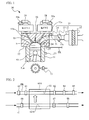
- FIG. 1 is a schematically structural view of an internal combustion engine 50 and related configurations.
- An intake system 10 includes an air cleaner 11, an air flow meter 12, an electronically controlled throttle 13, and an intake manifold 14.
- the air cleaner 11 filters the intake air.
- the air flow meter 12 measures the amount of the intake air GA of the internal combustion engine 50.
- the electronically controlled throttle 13 adjusts the amount of the intake air GA.
- the electronically controlled throttle 13 is provided with a throttle position sensor 13a.
- the intake manifold 14 distributes the intake air into each cylinder of the internal combustion engine 50.
- the intake manifold 14 is provided with an intake air temperature sensor 71.
- the internal combustion engine 50 is equipped with a cylinder block 51, a cylinder head 52, a piston 53, an intake valve 54, an exhaust valve 55, a spark plug 56, a fuel injection valve 57, an intake-side VVT (InVVT) 58, and an exhaust-side VVT (ExVVT) 59.
- the internal combustion engine 50 is provided with a water temperature sensor 72 for detecting a cooling water temperature THW, and is provided with a crank angle sensor 73 for detecting a crank angle.
- the cylinder block 51 is formed with a cylinder 51a.
- the piston 53 is housed in the cylinder 51a.
- the cylinder head 52 is secured with the upper surface of the cylinder block 51.
- the combustion chamber E is formed as a space surrounded by the cylinder block 51, the cylinder head 52, and the cylinder 53.
- the cylinder head 52 is formed with an intake port 52a for introducing the intake air to the combustion chamber E, and an exhaust port 52b for exhausting the gas from the combustion chamber E. Further, the cylinder head 52 is provided with the intake valve 54 for opening and closing the intake port 52a, and the exhaust valve 55 for opening and closing the exhaust port 52b.
- the spark plug 56 is provided in the cylinder head 52 such that an electrode projects from a center of an upper section of the combustion chamber E.
- the fuel injection valve 57 is provided in the cylinder head 52 such that an injection hole projects to the combustion chamber E.
- the fuel injection valve 57 is provided between the intake port 52a and the cylinder block 51 in the cylinder head 52.
- the fuel injection valve 57 injects the fuel directly into the combustion chamber E.
- the fuel injection valve 57 is not limited to this configuration.
- the fuel injection valve 57 may be arranged to inject the fuel to the intake port 52a.
- the fuel injection valve 57 is connected with a fuel supply path FR for supplying the fuel to the internal combustion engine 50.
- the cylinder head 52 is provided with the intake-side VVT 58 and the exhaust-side VVT 59.
- the intake-side VVT 58 is a variable valve mechanism that changes valve characteristics (for example, valve timing, and operation angle) of the intake valve 54.
- the exhaust-side VVT 59 is a variable valve mechanism that changes valve characteristics of the exhaust valve 55.
- the VVTs 58 and 59 are provided with state detection sensors 58a and 59a for detecting control states, respectively.
- FIG. 2 is a view of a main portion of the fuel supply path FR.
- the internal combustion engine 50 is equipped with a regulator 60A serving as a pressure adjustment portion capable of adjusting the pressure of the fuel injected to the fuel supply path FR.
- the regulator 60A is provided with a fuel flow portion 61 and a heating portion 62A.
- the fuel flow portion 61 is incorporated into the fuel supply path FR and causes the fuel to flow.
- the heating portion 62A is incorporated into a heat medium circulation path C causing a heat medium to circulate, and heats the fuel flowing in fuel flow portion 61 with the flowing heat medium.
- the fuel supply path FR is provided with an inlet-side fuel thermometer 81 and an outlet-side fuel thermometer 82 that detect the temperatures of the fuel at the upstream and downstream of the regulator 60A, respectively. Further, an inlet-side fuel pressure gauge 83 and an outlet-side fuel pressure gauge 84 are provided for detecting the fuel pressure. A fuel flow meter 85 is provided for detecting the flow rate of the fuel at an outlet-side of the regulator 60A.
- the multiple gaseous fuels flow in the fuel supply path FR.
- the internal combustion engine 50 uses multiple gaseous fuels as fuel.
- the multiple gaseous fuels to be used as fuel in the mixed state can flow in the fuel supply path FR.
- the multiple gaseous fuels are applicable to fuels, kinds of which are clarified but the mixture ratio of which is not clarified.
- the multiple gaseous fuels specifically includes hydrogen and CNG, and the mixture ratio thereof is not clarified.
- the heat medium circulation path C is provided with an inlet-side heat medium thermometer 86 and an outlet-side heat medium thermometer 87 that detect the temperatures of the heat medium at the upstream and downstream of the regulator 60A, respectively. Further, a heat medium flow meter 88 is provided for detecting the flow rate of the heat medium at the outlet side of the regulator 60A.
- the heat medium circulation path C can cause, for example, water to circulate therein.
- the heat medium may be cooling water for the internal combustion engine 50.
- FIG. 3 is a schematic diagram of an ECU 1A.
- the ECU 1A is an electronic control device serving as a controller device for an internal combustion engine.
- the ECU 1A is provided with a microcomputer composed of a CPU 2, a ROM 3, and a RAM 4, and input/output circuits 5 and 6.
- the CPU 2, the ROM 3, the RAM 4, and the input/output circuits 5 and 6 are connected via a bus 7.
- the ECU 1A is electrically connected with a sensor group including various sensors and switches. Also, the electronically controlled throttle 13 and the fuel injection valve 57 and the VVTs 58 and 59 are electrically connected as control objects.
- the sensor group S includes the air flow meter 12, the throttle position sensor 13a, the state detection sensors 58a and 59a, the intake air temperature sensor 71, the water temperature sensor 72, the crank angle sensor 73, the inlet-side fuel thermometer 81, the outlet-side fuel thermometer 82, the inlet-side fuel pressure gauge 83, and the outlet-side fuel pressure gauge 84, the fuel flow meter 85, the inlet-side heat medium thermometer 86, the outlet-side heat medium thermometer 87, and the heat medium flow meter 88.
- the ROM 3 is configured to store programs that describe various processes executed by the CPU 2 and map data.
- the CPU 2 executes the processes on the basis of the programs stored in the ROM 3 while using a temporary memory area formed in the RAM 4 as necessary.
- the ECU 1A functionally realizes various function portions such as a control portion, a heat variation amount estimation portion, and a mixture ratio estimation portion, as will be described later.
- the control portion performs the combustion control of the internal combustion engine 50 on the basis of the amount of heat variation of the fuel when the regulator 60A adjusts the pressure thereof.
- the amount of heat variation of the fuel in adjusting the pressure thereof can be grasped based on the amount of the heat transferred from the heating portion 62A to the fuel. This is because the amount of the heat transferred from the heating portion 62A to the fuel changes with the amount of the heat variation of the fuel in adjusting the pressure thereof.
- the heat variation amount estimation portion is an estimation portion that estimates the amount of heat variation of the fuel in adjusting the pressure thereof.
- the heat variation amount estimation portion estimates the amount of heat transferred from the heating portion 62A to the fuel per unit time on the basis of the specific heat of the heat medium, and the temperatures and the flow rates of the heat medium at the upstream and downstream of the regulator 60A. Thus, the amount of heat variation of the fuel in adjusting the pressure thereof is estimated.
- the mixture ratio estimation portion is an estimation portion that estimates the mixture ratio of the fuel to be used. Specifically, the mixture ratio estimation portion estimates the mixture ratio of the fuel to be used, on the basis of the amount of heat variation of the fuel when the pressure thereof is adjusted by the regulator 60A. This is because the amount of heat variation of the fuel in adjusting the pressure thereof changes with the mixture ratio of the fuel to be used. Thus, the mixture ratio of the fuel to be used is estimated by using the above property.
- FIG. 4 is a view of the relationship between the amount of transferred heat and the mixture ratio.
- a vertical axis indicates the amount of heat transferred from the heating portion 62A to the fuel.
- the perpendicular axis indicates the mixture ratio.
- the mixture ratio indicates a ratio of hydrogen to CHG. The mixture ratio increases as the ratio of hydrogen in the fuel increases. It is seen in FIG. 4 that the amount of transferred heat tends to decrease as the mixture ratio increases.
- the relationship illustrated in FIG. 4 is stored as map data in the ECU 1A beforehand.
- the relationship illustrated in FIG. 4 is established, under the condition that the fuel pressures at the upstream and downstream of the regulator 60A, and the temperature and the flow rate of the fuel at the inlet side of the regulator 60A belong to set and prepared ranges.
- the ECU 1A stores plural map data which define the relationships between the amount of transferred heat and the mixture ratio, and which correspond to the fuel pressures at the upstream and downstream of the regulator 60A, and the temperature and the flow rate of the fuel at the inlet side of the regulator 60A.
- the map data may be a single multidimensional map which defines the relationships between the amount of transferred heat and the mixture ratio, and which corresponds to the above ones.
- the mixture ratio estimation portion specifically detects the pressures of the fuel at the upstream and downstream of the regulator 60A, and the temperature and the flow rate of the fuel at the inlet side of the regulator 60A. Further, the corresponding map data is selected based on the detected pressures, the detected temperature, and the detected flow rate of the fuel. Furthermore, the mixture ratio corresponding to the amount of heat variation estimated by the heat variation amount estimation portion is read from the selected map data. Thus, the mixture ratio of the fuel to be used is estimated.
- the combustion control of the internal combustion engine 50 is performed on the basis of the amount of heat variation of the fuel in adjusting the pressure thereof.
- the control portion performs the combustion control of the internal combustion engine 50 on the basis of the mixture ratio, estimated by the mixture ratio estimation portion, of the fuel to be used.
- the control portion can control the electronically controlled throttle 13, the fuel injection valve 57, and the VVTs 58 and 59, when performing the combustion control of the internal combustion engine 50.
- the ECU 1A detects the temperatures and the flow rates of the heat medium at the upstream and downstream of the regulator 60A (step S1). Also, the pressures of the fuel at the upstream and downstream of the regulator 60A, the temperature and the flow rate of the fuel at the inlet side of the regulator 60A are detected (step S2). Sequentially, the ECU 1A estimates the amount of transferred heat based on the detection result obtained in step S1 and the specific heat of the heat medium (step S3). Also, the mixture ratio of the fuel to be used is estimated based on the detection result obtained in step S2 and the amount of transferred heat estimated in step S3 (step S4). Further, the combustion control of the internal combustion engine 50 is performed based on the estimated mixture ratio of the fuel to be used (step S5).
- the ECU 1A performs the combustion control of the internal combustion engine 50 on the basis of the amount of heat variation of the fuel when the regulator 60A adjusts the pressure thereof. Also, at this time, the mixture ratio of the fuel to be used is estimated on the basis of the amount of heat variation of the fuel when the regulator 60A adjusts the pressure thereof. In this regard, the amount of heat variation of the fuel can be estimated, for example, by providing the heating portion 62A in the regulator 60A.
- the ECU 1A does not need a detection device such as a gas analyzer device that tends to be expensive due to the special device, as for achieving appropriate combustion corresponding to the mixture ratio of the fuel to be used in the internal combustion engine 50. This facilitates reducing the cost. Also, as for estimating the amount of heat variation of the fuel in adjusting the pressure thereof, the heating portion 62A can be incorporated into the regulator 60A. This facilitates reducing the whole size of the configuration for grasping the mixture ratio of the fuel to be used. Regarding these points, the appropriate combustion corresponds to the mixture ratio of the use fuel can be preferably achieved.
- FIG. 6 is a view of a main portion of a fuel supply path FR'.
- the fuel supply path FR' is substantially the same as the fuel supply path FR, except that a regulator 60B is provided instead of the regulator 60A.
- the regulator 60B is substantially the same as the regulator 60A except that a heating portion 62B is provided instead of the heating portion 62A.
- the heating portion 62B is incorporated into a heater circuit H.
- the heater circuit H is provided with a power-supply unit 90, a voltmeter 91, an ammeter 92, and in addition to the heating portion 62B.
- the voltmeter 91 detects the voltage applied to the heating portion 62B.
- the ammeter 92 detects the current flowing through the heating portion 62B.
- the heating portion 62B is a resistor that heats the fuel flowing in the fuel flow portion 61 by generating electric heat.
- an ECU 1B is used instead of the ECU 1A.
- the ECU 1B is substantially the same as the ECU 1A, except that the ECU 1B is electrically connected with the voltmeter 91 and the ammeter 92 instead of the inlet-side heat medium thermometer 86, the outlet-side heat medium thermometer 87, and the heat medium flow meter 88, and except that the heat variation amount estimation portion is achieved as follows. Therefore, the illustration of the ECU 1B is omitted.
- the heat variation amount estimation portion estimates the amount of heat transferred from the heating portion 62B to the fuel per unit time on the basis of the voltage applied to the heating portion 62B and the current flowing therethrough. Thus, the amount of heat variation of the fuel in adjusting the pressure thereof is estimated.
- step S1' the ECU 1B detects the voltage applied to the heating portion 62B and the current flowing therethrough. Additionally, in step S3, the amount of heat variation of the fuel is estimated based on the detection result obtained in step S1'.
- the heating portion 62B can be used.
- the ECU 1B suitable for the heating portion 62B can reduce the cost and reduce the whole size of the configuration. This can preferably achieve the appropriate combustion corresponding to a mixture ratio of the fuel to be used.
- the amount of heat variation of the fuel which has the pressure adjusted by the pressure adjustment portion may be estimated by the heat variation amount estimation portion on the basis of the temperatures of the fuel at the upstream and downstream of the pressure adjustment portion.
- This case can achieve the appropriate combustion corresponding to a mixture ratio of the fuel to be used, without specifically providing a heating portion in a regulator. It is thus possible to further reduce the cost and reduce the whole size of the configuration.
Landscapes
- Engineering & Computer Science (AREA)
- Chemical & Material Sciences (AREA)
- Combustion & Propulsion (AREA)
- Mechanical Engineering (AREA)
- General Engineering & Computer Science (AREA)
- Chemical Kinetics & Catalysis (AREA)
- General Chemical & Material Sciences (AREA)
- Oil, Petroleum & Natural Gas (AREA)
- Combined Controls Of Internal Combustion Engines (AREA)
- Output Control And Ontrol Of Special Type Engine (AREA)
- Electrical Control Of Air Or Fuel Supplied To Internal-Combustion Engine (AREA)
Abstract
Description
- The present invention relates to a control device for an internal combustion engine.
- There is known an internal combustion engine using multiple gaseous fuels as fuel.
Patent Document 1 discloses a bi-fuel engine using the mixed fuel of liquefied petroleum gas and dimethylether as fuel, and discloses a method for estimating a mixture ratio of the mixed fuel. In addition,Patent Document 2 discloses a technique which may be related to the present invention. This technique is a control device for an internal combustion engine that determines whether the fuel is liquid or gaseous in using the liquid fuel and the gaseous fuel. -
- Patent Document 1: Japanese Patent Application Publication No.
2005-61401 - Patent Document 2: Japanese Patent Application Publication No.
2010-196667 - As for the internal combustion engine using multiple gaseous fuels as fuel, it is assumed that a mixture ratio of the fuel to be used changes whenever the fuel is supplied. However, the mixture ratio of the fuel to be used has to be grasped in order to perform appropriate combustion in the internal combustion engine. As for grasping the mixture ratio of the fuel to be used, it is desired to suppress an increase in cost, for example, caused by using a detection device that tends to be expensive due to the special device. Further, it is desired to reduce the whole size of the configuration required for grasping the mixture ratio of the fuel to be used.
- The present invention takes the above problem into consideration and aims at providing a control device for an internal combustion engine using multiple gaseous fuels as fuel, thereby preferably achieving appropriate combustion corresponding to a mixture ratio of the fuel to be used.
- The present invention is a control device for an internal combustion engine which uses multiple gaseous fuels as fuel and which is provided with a pressure adjustment portion capable of adjusting pressure of the fuel to be injected in a fuel supply path, the control device including a control portion that performs combustion control of the international combustion engine, on a basis of an amount of heat variation of the fuel when the pressure of the fuel is adjusted by the pressure adjustment portion.
- The present invention may further include an estimate portion that estimates a mixture ratio of the fuel to be used, on a basis of the amount of heat variation of the fuel when the pressure of the fuel is adjusted by the pressure adjustment portion, wherein the control portion may perform the combustion control of the international combustion engine on a basis of the mixture ratio, estimated by the estimate portion, of the fuel to be used, and the combustion control may be performed on a basis of the amount of heat variation of the fuel when the pressure of the fuel is adjusted by the pressure adjustment portion.
- The present invention is capable of providing a control device for an internal combustion engine using multiple gaseous fuels as fuel, thereby preferably achieving appropriate combustion corresponding to a mixture ratio of the fuel to be used.
-
-
FIG. 1 is a schematically structural view of a structural outline of an internal combustion engine and related configurations; -
FIG. 2 is a view of a main portion of a fuel supply path in a first embodiment; -
FIG. 3 is a schematic diagram of an ECU; -
FIG. 4 is a view of a relationship between an amount of transferred heat and a mixture ratio; -
FIG. 5 is a flowchart of a first control operation; -
FIG. 6 is a view of a main portion of a fuel supply path in a second embodiment; and -
FIG. 7 is a flowchart of a second control operation. - Embodiments of the invention are now described by referring to the drawings.
-
FIG. 1 is a schematically structural view of aninternal combustion engine 50 and related configurations. Anintake system 10 includes anair cleaner 11, anair flow meter 12, an electronically controlledthrottle 13, and anintake manifold 14. Theair cleaner 11 filters the intake air. Theair flow meter 12 measures the amount of the intake air GA of theinternal combustion engine 50. The electronically controlledthrottle 13 adjusts the amount of the intake air GA. The electronically controlledthrottle 13 is provided with athrottle position sensor 13a. Theintake manifold 14 distributes the intake air into each cylinder of theinternal combustion engine 50. Theintake manifold 14 is provided with an intakeair temperature sensor 71. - The
internal combustion engine 50 is equipped with acylinder block 51, acylinder head 52, apiston 53, anintake valve 54, anexhaust valve 55, aspark plug 56, afuel injection valve 57, an intake-side VVT (InVVT) 58, and an exhaust-side VVT (ExVVT) 59. Theinternal combustion engine 50 is provided with awater temperature sensor 72 for detecting a cooling water temperature THW, and is provided with acrank angle sensor 73 for detecting a crank angle. - The
cylinder block 51 is formed with acylinder 51a. Thepiston 53 is housed in thecylinder 51a. Thecylinder head 52 is secured with the upper surface of thecylinder block 51. The combustion chamber E is formed as a space surrounded by thecylinder block 51, thecylinder head 52, and thecylinder 53. Thecylinder head 52 is formed with anintake port 52a for introducing the intake air to the combustion chamber E, and anexhaust port 52b for exhausting the gas from the combustion chamber E. Further, thecylinder head 52 is provided with theintake valve 54 for opening and closing theintake port 52a, and theexhaust valve 55 for opening and closing theexhaust port 52b. - The
spark plug 56 is provided in thecylinder head 52 such that an electrode projects from a center of an upper section of the combustion chamber E. Thefuel injection valve 57 is provided in thecylinder head 52 such that an injection hole projects to the combustion chamber E. Thefuel injection valve 57 is provided between theintake port 52a and thecylinder block 51 in thecylinder head 52. Thefuel injection valve 57 injects the fuel directly into the combustion chamber E. Thefuel injection valve 57 is not limited to this configuration. For example, thefuel injection valve 57 may be arranged to inject the fuel to theintake port 52a. Thefuel injection valve 57 is connected with a fuel supply path FR for supplying the fuel to theinternal combustion engine 50. - The
cylinder head 52 is provided with the intake-side VVT 58 and the exhaust-side VVT 59. The intake-side VVT 58 is a variable valve mechanism that changes valve characteristics (for example, valve timing, and operation angle) of theintake valve 54. The exhaust-side VVT 59 is a variable valve mechanism that changes valve characteristics of theexhaust valve 55. TheVVTs state detection sensors -
FIG. 2 is a view of a main portion of the fuel supply path FR. Theinternal combustion engine 50 is equipped with aregulator 60A serving as a pressure adjustment portion capable of adjusting the pressure of the fuel injected to the fuel supply path FR. Theregulator 60A is provided with afuel flow portion 61 and aheating portion 62A. Thefuel flow portion 61 is incorporated into the fuel supply path FR and causes the fuel to flow. Theheating portion 62A is incorporated into a heat medium circulation path C causing a heat medium to circulate, and heats the fuel flowing infuel flow portion 61 with the flowing heat medium. - The fuel supply path FR is provided with an inlet-
side fuel thermometer 81 and an outlet-side fuel thermometer 82 that detect the temperatures of the fuel at the upstream and downstream of theregulator 60A, respectively. Further, an inlet-sidefuel pressure gauge 83 and an outlet-sidefuel pressure gauge 84 are provided for detecting the fuel pressure. Afuel flow meter 85 is provided for detecting the flow rate of the fuel at an outlet-side of theregulator 60A. - The multiple gaseous fuels flow in the fuel supply path FR. In this regard, the
internal combustion engine 50 uses multiple gaseous fuels as fuel. The multiple gaseous fuels to be used as fuel in the mixed state can flow in the fuel supply path FR. The multiple gaseous fuels are applicable to fuels, kinds of which are clarified but the mixture ratio of which is not clarified. The multiple gaseous fuels specifically includes hydrogen and CNG, and the mixture ratio thereof is not clarified. - The heat medium circulation path C is provided with an inlet-side
heat medium thermometer 86 and an outlet-sideheat medium thermometer 87 that detect the temperatures of the heat medium at the upstream and downstream of theregulator 60A, respectively. Further, a heatmedium flow meter 88 is provided for detecting the flow rate of the heat medium at the outlet side of theregulator 60A. The heat medium circulation path C can cause, for example, water to circulate therein. For example, the heat medium may be cooling water for theinternal combustion engine 50. -
FIG. 3 is a schematic diagram of anECU 1A. TheECU 1A is an electronic control device serving as a controller device for an internal combustion engine. TheECU 1A is provided with a microcomputer composed of aCPU 2, aROM 3, and aRAM 4, and input/output circuits 5 and 6. TheCPU 2, theROM 3, theRAM 4, and the input/output circuits 5 and 6 are connected via a bus 7. - The
ECU 1A is electrically connected with a sensor group including various sensors and switches. Also, the electronically controlledthrottle 13 and thefuel injection valve 57 and the VVTs 58 and 59 are electrically connected as control objects. The sensor group S includes theair flow meter 12, thethrottle position sensor 13a, thestate detection sensors air temperature sensor 71, thewater temperature sensor 72, thecrank angle sensor 73, the inlet-side fuel thermometer 81, the outlet-side fuel thermometer 82, the inlet-sidefuel pressure gauge 83, and the outlet-sidefuel pressure gauge 84, thefuel flow meter 85, the inlet-sideheat medium thermometer 86, the outlet-sideheat medium thermometer 87, and the heatmedium flow meter 88. - The
ROM 3 is configured to store programs that describe various processes executed by theCPU 2 and map data. TheCPU 2 executes the processes on the basis of the programs stored in theROM 3 while using a temporary memory area formed in theRAM 4 as necessary. Thus, theECU 1A functionally realizes various function portions such as a control portion, a heat variation amount estimation portion, and a mixture ratio estimation portion, as will be described later. - The control portion performs the combustion control of the
internal combustion engine 50 on the basis of the amount of heat variation of the fuel when theregulator 60A adjusts the pressure thereof. The amount of heat variation of the fuel in adjusting the pressure thereof can be grasped based on the amount of the heat transferred from theheating portion 62A to the fuel. This is because the amount of the heat transferred from theheating portion 62A to the fuel changes with the amount of the heat variation of the fuel in adjusting the pressure thereof. The heat variation amount estimation portion is an estimation portion that estimates the amount of heat variation of the fuel in adjusting the pressure thereof. Specifically, the heat variation amount estimation portion estimates the amount of heat transferred from theheating portion 62A to the fuel per unit time on the basis of the specific heat of the heat medium, and the temperatures and the flow rates of the heat medium at the upstream and downstream of theregulator 60A. Thus, the amount of heat variation of the fuel in adjusting the pressure thereof is estimated. - The mixture ratio estimation portion is an estimation portion that estimates the mixture ratio of the fuel to be used. Specifically, the mixture ratio estimation portion estimates the mixture ratio of the fuel to be used, on the basis of the amount of heat variation of the fuel when the pressure thereof is adjusted by the
regulator 60A. This is because the amount of heat variation of the fuel in adjusting the pressure thereof changes with the mixture ratio of the fuel to be used. Thus, the mixture ratio of the fuel to be used is estimated by using the above property. -
FIG. 4 is a view of the relationship between the amount of transferred heat and the mixture ratio. A vertical axis indicates the amount of heat transferred from theheating portion 62A to the fuel. The perpendicular axis indicates the mixture ratio. The mixture ratio indicates a ratio of hydrogen to CHG. The mixture ratio increases as the ratio of hydrogen in the fuel increases. It is seen inFIG. 4 that the amount of transferred heat tends to decrease as the mixture ratio increases. - The relationship illustrated in
FIG. 4 is stored as map data in theECU 1A beforehand. In this regard, the relationship illustrated inFIG. 4 is established, under the condition that the fuel pressures at the upstream and downstream of theregulator 60A, and the temperature and the flow rate of the fuel at the inlet side of theregulator 60A belong to set and prepared ranges. TheECU 1A stores plural map data which define the relationships between the amount of transferred heat and the mixture ratio, and which correspond to the fuel pressures at the upstream and downstream of theregulator 60A, and the temperature and the flow rate of the fuel at the inlet side of theregulator 60A. The map data may be a single multidimensional map which defines the relationships between the amount of transferred heat and the mixture ratio, and which corresponds to the above ones. - When the mixture ratio of the fuel to be used is estimated based on the amount of heat variation of the fuel in adjusting the pressure thereof, the mixture ratio estimation portion specifically detects the pressures of the fuel at the upstream and downstream of the
regulator 60A, and the temperature and the flow rate of the fuel at the inlet side of theregulator 60A. Further, the corresponding map data is selected based on the detected pressures, the detected temperature, and the detected flow rate of the fuel. Furthermore, the mixture ratio corresponding to the amount of heat variation estimated by the heat variation amount estimation portion is read from the selected map data. Thus, the mixture ratio of the fuel to be used is estimated. - In this regard, the combustion control of the
internal combustion engine 50 is performed on the basis of the amount of heat variation of the fuel in adjusting the pressure thereof. Specifically, the control portion performs the combustion control of theinternal combustion engine 50 on the basis of the mixture ratio, estimated by the mixture ratio estimation portion, of the fuel to be used. For example, the control portion can control the electronically controlledthrottle 13, thefuel injection valve 57, and the VVTs 58 and 59, when performing the combustion control of theinternal combustion engine 50. - Next, the operation of the
ECU 1A that is a first control operation will be described with reference to the flowchart illustrated inFIG. 5 . TheECU 1A detects the temperatures and the flow rates of the heat medium at the upstream and downstream of theregulator 60A (step S1). Also, the pressures of the fuel at the upstream and downstream of theregulator 60A, the temperature and the flow rate of the fuel at the inlet side of theregulator 60A are detected (step S2). Sequentially, theECU 1A estimates the amount of transferred heat based on the detection result obtained in step S1 and the specific heat of the heat medium (step S3). Also, the mixture ratio of the fuel to be used is estimated based on the detection result obtained in step S2 and the amount of transferred heat estimated in step S3 (step S4). Further, the combustion control of theinternal combustion engine 50 is performed based on the estimated mixture ratio of the fuel to be used (step S5). - Next, a description will be given of functions and effects of the
ECU 1A. TheECU 1A performs the combustion control of theinternal combustion engine 50 on the basis of the amount of heat variation of the fuel when theregulator 60A adjusts the pressure thereof. Also, at this time, the mixture ratio of the fuel to be used is estimated on the basis of the amount of heat variation of the fuel when theregulator 60A adjusts the pressure thereof. In this regard, the amount of heat variation of the fuel can be estimated, for example, by providing theheating portion 62A in theregulator 60A. - Therefore, the
ECU 1A does not need a detection device such as a gas analyzer device that tends to be expensive due to the special device, as for achieving appropriate combustion corresponding to the mixture ratio of the fuel to be used in theinternal combustion engine 50. This facilitates reducing the cost. Also, as for estimating the amount of heat variation of the fuel in adjusting the pressure thereof, theheating portion 62A can be incorporated into theregulator 60A. This facilitates reducing the whole size of the configuration for grasping the mixture ratio of the fuel to be used. Regarding these points, the appropriate combustion corresponds to the mixture ratio of the use fuel can be preferably achieved. -
FIG. 6 is a view of a main portion of a fuel supply path FR'. The fuel supply path FR' is substantially the same as the fuel supply path FR, except that aregulator 60B is provided instead of theregulator 60A. Theregulator 60B is substantially the same as theregulator 60A except that aheating portion 62B is provided instead of theheating portion 62A. Theheating portion 62B is incorporated into a heater circuit H. The heater circuit H is provided with a power-supply unit 90, avoltmeter 91, anammeter 92, and in addition to theheating portion 62B. Thevoltmeter 91 detects the voltage applied to theheating portion 62B. Theammeter 92 detects the current flowing through theheating portion 62B. For example, theheating portion 62B is a resistor that heats the fuel flowing in thefuel flow portion 61 by generating electric heat. - As for controlling the combustion of the
internal combustion engine 50, in the present embodiment, an ECU 1B is used instead of theECU 1A. The ECU 1B is substantially the same as theECU 1A, except that the ECU 1B is electrically connected with thevoltmeter 91 and theammeter 92 instead of the inlet-sideheat medium thermometer 86, the outlet-sideheat medium thermometer 87, and the heatmedium flow meter 88, and except that the heat variation amount estimation portion is achieved as follows. Therefore, the illustration of the ECU 1B is omitted. In the ECU 1B, the heat variation amount estimation portion estimates the amount of heat transferred from theheating portion 62B to the fuel per unit time on the basis of the voltage applied to theheating portion 62B and the current flowing therethrough. Thus, the amount of heat variation of the fuel in adjusting the pressure thereof is estimated. - Next, the operation of the ECU 1B that is a second control operation will be described with reference to the flowchart illustrated in
FIG. 7 . The flowchart illustrated inFIG. 7 is the same as the flowchart illustrated inFIG. 5 , except that step S1' is provided instead ofstep S 1. Thus, these will be specifically described herein. In step S1', the ECU 1B detects the voltage applied to theheating portion 62B and the current flowing therethrough. Additionally, in step S3, the amount of heat variation of the fuel is estimated based on the detection result obtained in step S1'. - Next, a description will be given of functions and effects of the ECU 1B. Herein, in order to estimate the amount of heat variation of the fuel in adjusting the pressure thereof, for example, the
heating portion 62B can be used. Like theECU 1A, the ECU 1B suitable for theheating portion 62B can reduce the cost and reduce the whole size of the configuration. This can preferably achieve the appropriate combustion corresponding to a mixture ratio of the fuel to be used. - The present invention is not limited to the specifically described embodiments, but may include other embodiments and variations without departing from the scope of the claimed invention.
- For example, the amount of heat variation of the fuel which has the pressure adjusted by the pressure adjustment portion may be estimated by the heat variation amount estimation portion on the basis of the temperatures of the fuel at the upstream and downstream of the pressure adjustment portion. This case can achieve the appropriate combustion corresponding to a mixture ratio of the fuel to be used, without specifically providing a heating portion in a regulator. It is thus possible to further reduce the cost and reduce the whole size of the configuration.
-
ECU 1A, 1B internal combustion engine 50 regulator 60A, 60B fuel flow portion 61 heating portion 62A, 62B
Claims (2)
- A control device for an internal combustion engine which uses multiple gaseous fuels as fuel and which is provided with a pressure adjustment portion capable of adjusting pressure of the fuel to be injected in a fuel supply path, the control device comprising
a control portion that performs combustion control of the international combustion engine, on a basis of an amount of heat variation of the fuel when the pressure of the fuel is adjusted by the pressure adjustment portion. - The control device for the internal combustion engine of claim 1, further comprising
an estimate portion that estimates a mixture ratio of the fuel to be used, on a basis of the amount of heat variation of the fuel when the pressure of the fuel is adjusted by the pressure adjustment portion,
wherein the control portion performs the combustion control of the international combustion engine on a basis of the mixture ratio, estimated by the estimate portion, of the fuel to be used, and the combustion control is performed on a basis of the amount of heat variation of the fuel when the pressure of the fuel is adjusted by the pressure adjustment portion.
Applications Claiming Priority (1)
| Application Number | Priority Date | Filing Date | Title |
|---|---|---|---|
| PCT/JP2011/065976 WO2013008322A1 (en) | 2011-07-13 | 2011-07-13 | Control device for internal combustion engine |
Publications (2)
| Publication Number | Publication Date |
|---|---|
| EP2733334A1 true EP2733334A1 (en) | 2014-05-21 |
| EP2733334A4 EP2733334A4 (en) | 2014-12-24 |
Family
ID=47505641
Family Applications (1)
| Application Number | Title | Priority Date | Filing Date |
|---|---|---|---|
| EP11869446.2A Withdrawn EP2733334A4 (en) | 2011-07-13 | 2011-07-13 | CONTROL DEVICE FOR INTERNAL COMBUSTION ENGINE |
Country Status (3)
| Country | Link |
|---|---|
| EP (1) | EP2733334A4 (en) |
| JP (1) | JP5590242B2 (en) |
| WO (1) | WO2013008322A1 (en) |
Family Cites Families (13)
| Publication number | Priority date | Publication date | Assignee | Title |
|---|---|---|---|---|
| US4944035A (en) * | 1988-06-24 | 1990-07-24 | Honeywell Inc. | Measurement of thermal conductivity and specific heat |
| JPH03285119A (en) * | 1990-03-31 | 1991-12-16 | Mazda Motor Corp | Alarming apparatus of remaining fuel in fuel tank |
| US5411005A (en) * | 1993-06-15 | 1995-05-02 | Bohl; Michael E. | Emissions and fuel control system and device |
| JP3448993B2 (en) * | 1994-12-01 | 2003-09-22 | マツダ株式会社 | Fuel supply system for gaseous fuel engine |
| DE19908885A1 (en) * | 1999-03-02 | 2000-09-07 | Fev Motorentech Gmbh | Method for operating gas burner by heating gas in separated measurement chamber and using relationship between and pressure or temperature to measure gas composition |
| US6612269B2 (en) * | 2000-08-11 | 2003-09-02 | The Regents Of The University Of California | Apparatus and method for operating internal combustion engines from variable mixtures of gaseous fuels |
| JP4003553B2 (en) * | 2002-06-26 | 2007-11-07 | Jfeスチール株式会社 | Power generation method and power generation facility using by-product gas |
| JP4389710B2 (en) | 2003-07-31 | 2009-12-24 | トヨタ自動車株式会社 | Bi-fuel engine and mixed fuel estimation method |
| JP2005320866A (en) * | 2004-05-06 | 2005-11-17 | Walbro Japan Inc | Change and supply device for different liquefied gas fuels |
| JP2008038729A (en) * | 2006-08-04 | 2008-02-21 | Yanmar Co Ltd | Control method of gas engine |
| JP2007032578A (en) * | 2006-11-02 | 2007-02-08 | Tokyo Gas Co Ltd | Operation control device for internal combustion engine |
| JP2009243711A (en) * | 2008-03-28 | 2009-10-22 | Ihi Corp | Combustion system |
| JP2010196667A (en) | 2009-02-27 | 2010-09-09 | Honda Motor Co Ltd | Control device of internal combustion engine |
-
2011
- 2011-07-13 JP JP2013523745A patent/JP5590242B2/en not_active Expired - Fee Related
- 2011-07-13 WO PCT/JP2011/065976 patent/WO2013008322A1/en not_active Ceased
- 2011-07-13 EP EP11869446.2A patent/EP2733334A4/en not_active Withdrawn
Also Published As
| Publication number | Publication date |
|---|---|
| JP5590242B2 (en) | 2014-09-17 |
| EP2733334A4 (en) | 2014-12-24 |
| JPWO2013008322A1 (en) | 2015-02-23 |
| WO2013008322A1 (en) | 2013-01-17 |
Similar Documents
| Publication | Publication Date | Title |
|---|---|---|
| KR102274486B1 (en) | engine operating device | |
| CN104121102B (en) | Fuel supply system and control method for micro diesel pilot direct injection natural gas engine | |
| CN105556101B (en) | Engine system with fuel quality sensor | |
| CA2969673C (en) | System and method for improving performance of combustion engines employing primary and secondary fuels | |
| US7024301B1 (en) | Method and apparatus to control fuel metering in an internal combustion engine | |
| US20120210988A1 (en) | Variable gas substitution for duel fuel engine and method | |
| RU2708564C2 (en) | Method of direct fuel injection in supercritical state (embodiments) | |
| US9657662B2 (en) | Determination of the quantity of fuel flowing through a fuel injector based on the heating of the fuel by means of an electric heating device | |
| JP2010038024A (en) | Fuel temperature control device of internal combustion engine | |
| TR201809346T4 (en) | Fuel system protection in an internal combustion engine with multi-fuel system. | |
| US20140026860A1 (en) | Apparatus and Method for Controlling Internal-Combustion Engine | |
| KR20040038849A (en) | Gasoline Alternative Fuel Injection Control Apparatus of Engine | |
| KR20130109431A (en) | Apparatus for controling exhaust gas recirculation and method thereof | |
| JP2009185676A (en) | Fuel supply device for internal combustion engine | |
| MXPA05010716A (en) | Capillary heating control and fault detection system and methodology for fuel system in an internal combustion engine. | |
| EP2733334A1 (en) | Control device for internal combustion engine | |
| CN203978671U (en) | The diesel oil ignited direct-jet natural gas engine fuel supply system of trace | |
| EP2935845B1 (en) | Exhaust gas recirculation control method and system | |
| CN213235265U (en) | Gas supply system | |
| US20150114357A1 (en) | Fuel injection control device and fuel injection control method | |
| CN109899168A (en) | A kind of binodal air valve engine control system applied to generating set | |
| CN114370345A (en) | Method and device for controlling gas fuel injection amount, and storage medium | |
| JP2010275879A (en) | Fuel vapor pressure measurement system | |
| CN116988869B (en) | Combustion control system and control method for gas ignition engine | |
| CN105525958B (en) | The detection method and control method of engine VVT systems |
Legal Events
| Date | Code | Title | Description |
|---|---|---|---|
| PUAI | Public reference made under article 153(3) epc to a published international application that has entered the european phase |
Free format text: ORIGINAL CODE: 0009012 |
|
| 17P | Request for examination filed |
Effective date: 20131209 |
|
| AK | Designated contracting states |
Kind code of ref document: A1 Designated state(s): AL AT BE BG CH CY CZ DE DK EE ES FI FR GB GR HR HU IE IS IT LI LT LU LV MC MK MT NL NO PL PT RO RS SE SI SK SM TR |
|
| DAX | Request for extension of the european patent (deleted) | ||
| A4 | Supplementary search report drawn up and despatched |
Effective date: 20141120 |
|
| RIC1 | Information provided on ipc code assigned before grant |
Ipc: F02D 41/00 20060101ALI20141114BHEP Ipc: F02M 21/02 20060101ALI20141114BHEP Ipc: F02D 19/02 20060101ALI20141114BHEP Ipc: F02M 53/02 20060101ALI20141114BHEP Ipc: F02D 45/00 20060101ALI20141114BHEP Ipc: F02D 19/08 20060101AFI20141114BHEP |
|
| 17Q | First examination report despatched |
Effective date: 20150928 |
|
| STAA | Information on the status of an ep patent application or granted ep patent |
Free format text: STATUS: THE APPLICATION IS DEEMED TO BE WITHDRAWN |
|
| 18D | Application deemed to be withdrawn |
Effective date: 20160209 |