EP2733112A1 - Method and apparatus for applying sealing capsules to bottle necks provided with a retaining cage of metal wire. - Google Patents
Method and apparatus for applying sealing capsules to bottle necks provided with a retaining cage of metal wire. Download PDFInfo
- Publication number
- EP2733112A1 EP2733112A1 EP13004684.0A EP13004684A EP2733112A1 EP 2733112 A1 EP2733112 A1 EP 2733112A1 EP 13004684 A EP13004684 A EP 13004684A EP 2733112 A1 EP2733112 A1 EP 2733112A1
- Authority
- EP
- European Patent Office
- Prior art keywords
- capsule
- bottle
- tab
- slot
- cage
- Prior art date
- Legal status (The legal status is an assumption and is not a legal conclusion. Google has not performed a legal analysis and makes no representation as to the accuracy of the status listed.)
- Granted
Links
- 239000002775 capsule Substances 0.000 title claims abstract description 80
- 210000003739 neck Anatomy 0.000 title claims abstract description 35
- 238000000034 method Methods 0.000 title claims description 22
- 239000002184 metal Substances 0.000 title claims description 11
- 238000007789 sealing Methods 0.000 title claims description 10
- 230000002093 peripheral effect Effects 0.000 claims abstract description 4
- 230000004913 activation Effects 0.000 claims 1
- 230000002452 interceptive effect Effects 0.000 claims 1
- 238000004519 manufacturing process Methods 0.000 description 17
- 239000007799 cork Substances 0.000 description 4
- 238000003780 insertion Methods 0.000 description 2
- 230000037431 insertion Effects 0.000 description 2
- 238000012423 maintenance Methods 0.000 description 2
- 238000005452 bending Methods 0.000 description 1
- 235000019993 champagne Nutrition 0.000 description 1
- 230000001419 dependent effect Effects 0.000 description 1
- 239000000463 material Substances 0.000 description 1
- 230000003287 optical effect Effects 0.000 description 1
- 230000000717 retained effect Effects 0.000 description 1
- 239000000523 sample Substances 0.000 description 1
- 235000015040 sparkling wine Nutrition 0.000 description 1
- 229920002994 synthetic fiber Polymers 0.000 description 1
Images


Classifications
-
- B—PERFORMING OPERATIONS; TRANSPORTING
- B67—OPENING, CLOSING OR CLEANING BOTTLES, JARS OR SIMILAR CONTAINERS; LIQUID HANDLING
- B67B—APPLYING CLOSURE MEMBERS TO BOTTLES JARS, OR SIMILAR CONTAINERS; OPENING CLOSED CONTAINERS
- B67B5/00—Applying protective or decorative covers to closures; Devices for securing bottle closures with wire
- B67B5/03—Applying protective or decorative covers to closures, e.g. by forming in situ
-
- B—PERFORMING OPERATIONS; TRANSPORTING
- B67—OPENING, CLOSING OR CLEANING BOTTLES, JARS OR SIMILAR CONTAINERS; LIQUID HANDLING
- B67B—APPLYING CLOSURE MEMBERS TO BOTTLES JARS, OR SIMILAR CONTAINERS; OPENING CLOSED CONTAINERS
- B67B2201/00—Indexing codes relating to constructional features of closing machines
- B67B2201/01—Orienting closure means
- B67B2201/017—Caps
Definitions
- the present invention relates to a method of applying sealing capsules to bottle necks provided with a retaining cage of metal wire, and to an apparatus for carrying out such method.
- the mouth of the bottle is corked by a plug consisting of an agglomerate of cork or synthetic material, which is plugged into the bottle neck in a corking station.
- a wirehood i.e., a cage of metal wire
- the closure is secured by fastening a wirehood, i.e., a cage of metal wire, about the bottle neck, which wirehood retains the cork from being expelled by the pressure inside the bottle.
- a capsule of a deformable material typically a thin metal sheet, which is applied to the bottle neck.
- the capsule which initialy has a slightly tapered frustoconical shape, is loosely fitted on the bottle neck by a capsule dispenser, and then it is made to adhere to the bottle wall by a capsule-folding/smoothening machine.
- the base of the wirehood typically consists of a ring made of the same metal wire, which is fastened about the bottle neck, below the neck finish, by twisting a portion of the wire in such a way as to form a locking tab which terminates with a loop.
- the loop is grasped and untwisted, thereby opening the base of the wirehood and allowing the latter to be removed.
- the locking tab of the wirehood is bent against the bottle wall and is hidden by the capsule, which completely covers the bottle neck with the cork and the wirehood.
- capsules which are provided with an I-shaped slot, through which the locking tab protrudes.
- Fig. 1 illustrates an apparatus 10 for applying sealing capsules to bottle necks N in the configuration of Fig. 2 , in which the mouth M of the bottle is closed by a cork P, which is retained in its position by a retaining cage of metal wire, or wirehood, C.
- the base of the wirehood conventionally consists of a ring R made of the same metal wire, which is fastened about bottle neck N, below the neck finish Q, by twisting a portion of the base to form a locking tab L.
- standard productions i.e., those productions in which locking tab L is to be covered by a capsule, before receiving the capsules the bottles are configured as shown in Fig. 2 , with locking tab L bent against the bottle wall.
- wirehood C is assumed to have a predetermined alignment with respect to the bottle, e.g., with locking tab L rotated by 90° in the counter-clock direction (when the bottle is wached from above) with respect to a label (not shown); Therefore, the opener who holds the bottle with her/his left hand and grasps the locking tab with her/his right hand, will have the label in front of her/him.
- the corking/aligning/wirehooding operations may be carried out conventionally by standard processes and machines which do not fall within the scope of the present invention and therefore are not discussed herein.
- bottles B in the above-described configuration shown in Fig. 2 are carried by a conveyor belt 12 flanked by an auger 14, which is adapted to maintain the bottles equally spaced from each other.
- a capsule dispenser 16 is arranged at the inlet end of auger 14 for laying a sealing capsule on each of the bottles carried by conveyor belt 12.
- An expulsion starwheel 18 is arranged immediately downstream of capsule dispenser 16 for removing any bottles to be discarded from the line, where necessary.
- capsules 20 placed on the bottle necks are of the known type shown in Fig. 3 , having a I-shaped slot 22 on its lateral wall which is adapted to be passed though by locking tab L of wirehood C.
- the capsules will have a random orientation with respect to the respective bottles and to the wirehoods C associated to the latter.
- a first transfer starwheel 26 arranged downstream of expulsion starwheel 18 draws the bottles from conveyor belt 12 and, according to the invention, transfers them to an encapsulating carousel 28 having a plurality of peripheral stations such as 30, e.g., twenty stations, each of which is equipped to carry out the operations described in detail below.
- arched lines A1, A2, A3, A4, A5, A6 in Fig. 1 engage respective portions of the rotation of the station, which are depicted by arched lines A1, A2, A3, A4, A5, A6 in Fig. 1 . Certain operations are carried out simultaneously, at least partially; therefore, in some cases, the arched lines are overlapped.
- a turntable 32 supports bottle B in each of the stations.
- turntable 32 is rotated in such a way as to provide locking tab L of wirehood C with a predetermined orientation with respect to the station. Since, as mentioned above, wirehood C in this embodiment is assumed to have a predetermined orientation with respect to bottle B, a reference on bottle B, e.g., a recess S as typically formed on the base of the bottle, can be used for orienting the wirehood.
- a detector 34 e.g., a mechanical probe or a photoelectric cell, in a way known per se detects recess S, thereby allowing the bottle to be oriented on the basis of it, as mentioned above.
- neck N of bottle B is engaged by a capsule-centering head 36, which comprises a sucker-based, pick-up device 38 mounted at the lower end of a vertical suction duct 39, which is operatively connected to conventional suction means (not shown).
- Vertical suction duct 39 can both shift vertically and rotate axially.
- a sleeve 40 is axially slidable on vertical suction duct 39 and is suitably sized to surround the capsule with a close fit.
- sleeve 40 is lowered about the bottle neck, while pick-up device 38 is stationary near the top of the capsule.
- pick-up device 38 is enabled to catch capsule 20, and then is raised, along with sleeve 40, so that capsule 20 is disengaged from neck N of bottle B.
- Pick-up device 38 is then rotated to provide slot 22 of capsule 20 with the same alignment of locking tab L with respect to the station, whereby slot 22 is aligned to locking tab L.
- a reference notch T which is conventionally printed on the capsule ( Fig. 3 ) and can be detected by an optical sensor 42 in a way known per se, is used for orienting the capsule.
- the next step is depicted in Fig. 1 by arched line A3.
- arched line A3 is partially overlapped to arched line A2 as the two steps are partially simultaneous.
- a motorized opening device 44 partially bends locking tab L of wirehood C outwards to an oblique position forming an angle of about 45° with respect to the vertical direction; however, the optimum angle for the locking tab can be determined experimentally on the basis of the real shapes of the capsule and the locking tab, as well as on the position of the slot.
- the opening device consists of a hook 44a hinged to a slide 44b which is slidable horizontally on a guide 44c.
- a locking device 46 which comprises a support 48 having two counterposed jaws 50, 52 hinged thereto, which are provided with respective pairs of rollers 54, 56 via which they clamp the bottle on respective opposite sides thereof.
- the next step ( Fig. 8 ) is depicted in Fig. 1 by arched line A4. As shown, arched line A4 is overlapped to the end portion of arched line A3, thereby indicating that the two steps may be carried out simultaneously. In this step, sleeve 40 of capsule-centering head 39 is raised with respect to pick-up device 38, so that capsule 20 is uncovered.
- a pneumatically driven punch 57 hits the lateral wall of capsule 20 at slot 22, so that the two fins 23a, 23b ( Fig. 3 ) defined between the horizontal segments of the I-shape are slightly bent inwards.
- the bottle is returned to conveyor belt 12 by a second transfer starwheel 58, and then is conveyed to successive stations 60, in which capsule-bending/smoothening operations are carried out in a traditional manner; these final operations, which are well known per se and can be carried out in a conventional manner, will not be described herein.
- the various movable parts of the apparatus can be driven by conventional electrical and/or pneumatic and/or hydraulic motors/actuators (not shown for simplicity) controlled by a control unit, the programming of which falls within the normal knowledge of a skilled person and therefore will not be disclosed herein.
- a considerable advantage of the method according to the invention, as well as of the apparatus for carrying out the method, is that the operations of pulling the locking tab out of the slot are all performed on a carousel arranged beside a traditional line; the capsuled bottles are received by the carousel with a random orientation of the capsules with respect to the bottles - i.e., the same configuration at this stage of a standard production - and are returned in the same condition but with the locking tab projecting outwards from the capsule. Therefore, having a carousel properly sized and provided with an adequate number of stations, all the above-described steps can be carried out without reduction of the production yield with respect to standard productions.
- the apparatus can still be used for standard productions, so that the continuity of the production is not affected.
- the apparatus of the invention can be easily integrated in a traditional bottling plant, by simply relocating the various stations in such a way as to make room for carousel 28, with normal changes for a person skilled in the art.
- the locking tab and the slot are aligned to each other indirectly, i.e., both the wirehood and the capsule are oriented on the basis of another fixed reference.
- the method can be changed so that the position of the locking tab is detected and the capsule is oriented as a function of the detected position of the locking tab, or vice versa.
- the sequence of the operations carried out on the carousel in certain cases, can be modified. For instance, the capsule can be oriented after that the locking tab has been bent, rather than before, and the bottle and the capsule can be aligned at the same time (second step, A2).
- the wirehood is assumed to have a predetermined orientation with respect to the bottle; therefore, the capsule is oriented on the basis of a reference on the bottle.
- the locking tab of the wirehood could be used as a reference for the alignment or, as mentioned above, the position of the locking tab can be detected and the capsule aligned directly to it.
- the number of stations of the carousel can be changed and optimized as a function of the desired production yield.
Landscapes
- Auxiliary Devices For And Details Of Packaging Control (AREA)
- Sealing Of Jars (AREA)
- Walking Sticks, Umbrellas, And Fans (AREA)
- Ropes Or Cables (AREA)
Abstract
Description
- The present invention relates to a method of applying sealing capsules to bottle necks provided with a retaining cage of metal wire, and to an apparatus for carrying out such method.
- As known, sparkling wines, champagne, and the like, nowadays are bottled in series by apparatuses which receive the bottles in sequence and carry out all the bottling operations upon them, from the filling step to the sealing step.
- In particular, after the filling step, the mouth of the bottle is corked by a plug consisting of an agglomerate of cork or synthetic material, which is plugged into the bottle neck in a corking station. Then, in a wirehooding station, the closure is secured by fastening a wirehood, i.e., a cage of metal wire, about the bottle neck, which wirehood retains the cork from being expelled by the pressure inside the bottle. The whole thing is finally sealed by a capsule of a deformable material, typically a thin metal sheet, which is applied to the bottle neck. The capsule, which initialy has a slightly tapered frustoconical shape, is loosely fitted on the bottle neck by a capsule dispenser, and then it is made to adhere to the bottle wall by a capsule-folding/smoothening machine.
- The base of the wirehood typically consists of a ring made of the same metal wire, which is fastened about the bottle neck, below the neck finish, by twisting a portion of the wire in such a way as to form a locking tab which terminates with a loop. In order to open the bottle, the loop is grasped and untwisted, thereby opening the base of the wirehood and allowing the latter to be removed.
- With standard productions, the locking tab of the wirehood is bent against the bottle wall and is hidden by the capsule, which completely covers the bottle neck with the cork and the wirehood.
- However, certain high quality productions require that the locking tab protrudes from the capsule, in order to make it easier to access it for opening the bottle. To this purpose, capsules have been made which are provided with an I-shaped slot, through which the locking tab protrudes.
- These particular applications require specific bottling plants in which the capsule, according to the prior art, before being placed on the bottle neck is properly oriented so that the slot of the capsule is aligned to the locking tab of the wirehood; moreover, after that a portion of the base has been twisted to form the locking tab, the latter is not bent against the bottle neck but is maintained in its configuration protruding outwards - i.e., the configuration of the portion of metal wire of the wirehood base immediately after that it has been twisted - in order to facilitate the correct insertion of the locking tab through the slot when the capsule is placed on the bottle neck.
- All the above preliminary operations, which are performed in line before placing the capsule on the bottle neck, have the drawback that they considerably slow down the process, with a reduction of up to 30% in the production yield with respect to standard productions, in which the locking tab is covered by the capsule.
- A further drawback of the above-mentiond, known bottling plants is that, even when used for standard productions, the bottles and the capsules must always pass through all the above-cited preliminary operations which, although disabled, inevitably slow down the process.
- In addition, in case of failure, jamming, or any other need for maintenance in one of the stations in which the preliminary operations are carried out, all the production line must inevitably be stopped until the problem has been solved, and can not even be used for standard productions which do not require any preliminary operation.
- Therefore, it is a main object of the present invention to provide a method of applying sealing capsules to bottle necks provided with a retaining cage of metal wire, and to an apparatus for carrying out such method, which overcome the above mentioned drawbacks of the conventional systems.
- The above object and other advantages, which will clearly appear from the following description, are achieved by a method having the features recited in claim 1 and by an apparatus having the features recited in claim 6, while the dependent claims state other advantageous, though secondary features of the invention.
- The invention will be now described in more detail, with reference to a preferred, non-exclusive embodiment, shown by way of non-limiting example in the attached drawings, wherein:
-
Fig. 1 is a diagrammatical plan view of an apparatus for applying sealing capsules to bottle necks according to the invention; -
Fig. 2 is a view in side elevation of a corked bottle neck conventionally provided with a wirehood; -
Fig. 3 is a view in side elevation of a sealing capsule of a conventional type provided with an I-shaped slot; -
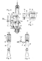
Fig. 4 is a view in axial cross section of a bottle supported by the apparatus according to the invention in a first step of the method; -
Fig. 5 is a view in axial cross section of a bottle supported by the apparatus according to the invention in a second step of the method; -
Fig. 6 is a view in axial cross section of a bottle supported by the apparatus according to the invention in a third step of the method; -
Fig. 7 is a view in cross section ofFig. 6 along axis VII-VII; -
Fig. 8 is a view in axial cross section of a bottle supported by the apparatus according to the invention in a fourth step of the method; -
Fig. 9 is a view in axial cross section of a bottle supported by the apparatus according to the invention in a fifth step of the method; -
Fig. 10 is a view in axial cross section of a bottle supported by the apparatus according to the invention in a sixth step of the method, which is shown to an enlarged scale with respect to the preceding steps. -
Fig. 1 illustrates anapparatus 10 for applying sealing capsules to bottle necks N in the configuration ofFig. 2 , in which the mouth M of the bottle is closed by a cork P, which is retained in its position by a retaining cage of metal wire, or wirehood, C. The base of the wirehood conventionally consists of a ring R made of the same metal wire, which is fastened about bottle neck N, below the neck finish Q, by twisting a portion of the base to form a locking tab L. With standard productions, i.e., those productions in which locking tab L is to be covered by a capsule, before receiving the capsules the bottles are configured as shown inFig. 2 , with locking tab L bent against the bottle wall. Moreover, in the embodiment described herein, wirehood C is assumed to have a predetermined alignment with respect to the bottle, e.g., with locking tab L rotated by 90° in the counter-clock direction (when the bottle is wached from above) with respect to a label (not shown); Therefore, the opener who holds the bottle with her/his left hand and grasps the locking tab with her/his right hand, will have the label in front of her/him. The corking/aligning/wirehooding operations may be carried out conventionally by standard processes and machines which do not fall within the scope of the present invention and therefore are not discussed herein. - Having particular reference to the
apparatus 10 ofFig. 1 , bottles B in the above-described configuration shown inFig. 2 are carried by aconveyor belt 12 flanked by anauger 14, which is adapted to maintain the bottles equally spaced from each other. Acapsule dispenser 16 is arranged at the inlet end ofauger 14 for laying a sealing capsule on each of the bottles carried byconveyor belt 12. Anexpulsion starwheel 18 is arranged immediately downstream ofcapsule dispenser 16 for removing any bottles to be discarded from the line, where necessary. - The foregoing is all known and conventional in the field in relation to standard productions, except that
capsules 20 placed on the bottle necks are of the known type shown inFig. 3 , having a I-shaped slot 22 on its lateral wall which is adapted to be passed though by locking tab L of wirehood C. However, the capsules will have a random orientation with respect to the respective bottles and to the wirehoods C associated to the latter. - A
first transfer starwheel 26 arranged downstream ofexpulsion starwheel 18 draws the bottles fromconveyor belt 12 and, according to the invention, transfers them to an encapsulatingcarousel 28 having a plurality of peripheral stations such as 30, e.g., twenty stations, each of which is equipped to carry out the operations described in detail below. - The various operations engage respective portions of the rotation of the station, which are depicted by arched lines A1, A2, A3, A4, A5, A6 in
Fig. 1 . Certain operations are carried out simultaneously, at least partially; therefore, in some cases, the arched lines are overlapped. - With particular reference to
Figs. 4-10 , aturntable 32 supports bottle B in each of the stations. - In a first step, as shown in
Fig. 4 and depicted by arched line A1 inFig. 1 ,turntable 32 is rotated in such a way as to provide locking tab L of wirehood C with a predetermined orientation with respect to the station. Since, as mentioned above, wirehood C in this embodiment is assumed to have a predetermined orientation with respect to bottle B, a reference on bottle B, e.g., a recess S as typically formed on the base of the bottle, can be used for orienting the wirehood. Adetector 34, e.g., a mechanical probe or a photoelectric cell, in a way known per se detects recess S, thereby allowing the bottle to be oriented on the basis of it, as mentioned above. - In this first step, neck N of bottle B is engaged by a capsule-centering
head 36, which comprises a sucker-based, pick-updevice 38 mounted at the lower end of avertical suction duct 39, which is operatively connected to conventional suction means (not shown).Vertical suction duct 39 can both shift vertically and rotate axially. Asleeve 40 is axially slidable onvertical suction duct 39 and is suitably sized to surround the capsule with a close fit. In this first step,sleeve 40 is lowered about the bottle neck, while pick-updevice 38 is stationary near the top of the capsule. - In the next step, as shown in
Fig. 5 and depicted by arched line A2 inFig. 1 , pick-updevice 38 is enabled to catchcapsule 20, and then is raised, along withsleeve 40, so thatcapsule 20 is disengaged from neck N of bottle B. Pick-updevice 38 is then rotated to provideslot 22 ofcapsule 20 with the same alignment of locking tab L with respect to the station, wherebyslot 22 is aligned to locking tab L. A reference notch T, which is conventionally printed on the capsule (Fig. 3 ) and can be detected by anoptical sensor 42 in a way known per se, is used for orienting the capsule. - The next step (Figg. 6 and 7) is depicted in
Fig. 1 by arched line A3. As shown, arched line A3 is partially overlapped to arched line A2 as the two steps are partially simultaneous. In this step (Fig. 6 ), whilecapsule 20 is raised, a motorizedopening device 44 partially bends locking tab L of wirehood C outwards to an oblique position forming an angle of about 45° with respect to the vertical direction; however, the optimum angle for the locking tab can be determined experimentally on the basis of the real shapes of the capsule and the locking tab, as well as on the position of the slot. In the embodiment described herein, the opening device consists of a hook 44a hinged to a slide 44b which is slidable horizontally on aguide 44c. - While locking tab L is opened, the bottle is held laterally by a
locking device 46, which comprises asupport 48 having two counterposedjaws rollers - The next step (
Fig. 8 ) is depicted inFig. 1 by arched line A4. As shown, arched line A4 is overlapped to the end portion of arched line A3, thereby indicating that the two steps may be carried out simultaneously. In this step,sleeve 40 of capsule-centeringhead 39 is raised with respect to pick-updevice 38, so thatcapsule 20 is uncovered. - In the next step (
Fig. 9 ) depicted inFig. 1 by arched line A5, a pneumatically drivenpunch 57 hits the lateral wall ofcapsule 20 atslot 22, so that the two fins 23a, 23b (Fig. 3 ) defined between the horizontal segments of the I-shape are slightly bent inwards. - In the last step (
Fig. 10 ) depicted inFig. 1 by arched line A6, the capsule is laid on the bottle again, withsleeve 40 remaining in its raised position. During the descent of the capsule, locking tab L of wirehood C slips under the lower edge of fins 22a, 22b ofslot 22, which have been previously bent inwards in order to facilitate this insertion, and leans out fromcapsule 20. - Having now reference to
Fig. 1 , after the last step the bottle is returned toconveyor belt 12 by asecond transfer starwheel 58, and then is conveyed tosuccesive stations 60, in which capsule-bending/smoothening operations are carried out in a traditional manner; these final operations, which are well known per se and can be carried out in a conventional manner, will not be described herein. - Of course, the various movable parts of the apparatus can be driven by conventional electrical and/or pneumatic and/or hydraulic motors/actuators (not shown for simplicity) controlled by a control unit, the programming of which falls within the normal knowledge of a skilled person and therefore will not be disclosed herein.
- As the person skilled in the art will easily appreciate, a considerable advantage of the method according to the invention, as well as of the apparatus for carrying out the method, is that the operations of pulling the locking tab out of the slot are all performed on a carousel arranged beside a traditional line; the capsuled bottles are received by the carousel with a random orientation of the capsules with respect to the bottles - i.e., the same configuration at this stage of a standard production - and are returned in the same condition but with the locking tab projecting outwards from the capsule. Therefore, having a carousel properly sized and provided with an adequate number of stations, all the above-described steps can be carried out without reduction of the production yield with respect to standard productions.
- In addition, in order to use the apparatus of the invention for standard productions, it is sufficient to disable
carousel 28, so that the bottles are directly transferred fromcapsule dispenser 16 tofinal stations 60. - Similarly, if
carousel 28 must be stopped for maintenance, the apparatus can still be used for standard productions, so that the continuity of the production is not affected. - In addition, the apparatus of the invention can be easily integrated in a traditional bottling plant, by simply relocating the various stations in such a way as to make room for
carousel 28, with normal changes for a person skilled in the art. - A preferred embodiment of the invention has been described herein, but of course many changes may be made by a person skilled in the art within the scope of the claims. For instance, with the embodiment described herein the locking tab and the slot are aligned to each other indirectly, i.e., both the wirehood and the capsule are oriented on the basis of another fixed reference. However, the method can be changed so that the position of the locking tab is detected and the capsule is oriented as a function of the detected position of the locking tab, or vice versa. Moreover, the sequence of the operations carried out on the carousel, in certain cases, can be modified. For instance, the capsule can be oriented after that the locking tab has been bent, rather than before, and the bottle and the capsule can be aligned at the same time (second step, A2). In addition, depending on the real shape of the slot and the locking tab, as well as on the conicity of the capsule, a preforming of the capsule at the slot could be not necessary (fifth step, A5). Moreover, with the above-described embodiment, the wirehood is assumed to have a predetermined orientation with respect to the bottle; therefore, the capsule is oriented on the basis of a reference on the bottle. However, if the wirehood has a random orientation, the locking tab of the wirehood could be used as a reference for the alignment or, as mentioned above, the position of the locking tab can be detected and the capsule aligned directly to it. Of course, the number of stations of the carousel can be changed and optimized as a function of the desired production yield.
Claims (10)
- A method of applying sealing capsules to the necks of corked bottles provided with a cork-retaining cage made of metal wire (C) and having a locking tab (L) bent towards the wall of the bottle, characterized in that it comprises the steps of:- feeding the bottles to a capsule dispenser (16) which is adapted to place a capsule (20) having a slot (22) on its lateral wall upon each of the bottle necks (N),- feeding the capsuled bottles to a carousel (28) provided with a plurality of peripheral stations (30), each of which is adapted to receive a respective bottle (B) and to perform the following operations upon it:- raising the capsule (20) from the neck (N) by a pick-up device (38),- opening outwards the tab (L) of the cage (C) at least partially, by an opening device,- aligning said tab (L) to said slot (22) by axially rotating at least one of said bottle (B) and capsule (20),- re-laying said capsule (20) on the bottle neck, said tab (L) inserting into the slot (22) and protruding outside the capsule.
- The method of claim 1, characterized in that, before laying the capsule (20) on the bottle neck, the lateral wall of the capsule is deformed at the slot (22) by deforming means (57) adapted to suitably shape the slot (22) for receiving said tab (L).
- The method of claim 1, characterized in that said opening device (44) opens the tab (L) outwards at an angle of about 45° with respect to the vertical direction.
- The method of claim 1, characterized in that said operation of aligning said tab (L) to said slot (22) on the capsule (20) comprises the steps of:- rotating the bottle (B) about its axis in such a way as to arrange the tab (L) of the cage at a predetermined orientation with respect to the respective station (30), and- rotating the capsule (20) about its axis in such a way as to arrange the slot (22) with the same predetermined orientation with respect to the station (30).
- An apparatus for applying sealing capsules to the necks of corked bottles provided with a cork-retaining cage made of metal wire (C) and having a locking tab (L) bent towards the wall of the bottle, characterized in that it comprises a capsule dispenser (16) which is adapted to place a capsule having a slot (22) on its lateral wall upon each of the bottle necks, and a carousel (28) provided with a plurality of peripheral stations (30) each adapted to receive a respective bottle and provided with:- pick-up means (40) operable to raise the capsule (20) from the bottle neck (N) at a position such that the access to said tab (L) is not obstructed, and successively re-laying it,- opening means (44) operable to open the tab (L) outwards at least partially, while said capsule (20) is at its raised position,- orienting means (32, 34, 38, 42) operable to axially rotate at least one of said bottle (B) and capsule (20), in such a way as to align said tab (L) of the cage (C) to said slot (22) of the capsule (20), before the latter is re-laid.
- The apparatus of claim 5, characterized in that it comprises deforming means (57) operable to deform the lateral wall of the capsule at the slot (22) in such a way as to suitably shape the latter for receiving said tab (L) before said capsule (20) is re-laid on the bottle neck.
- The apparatus of claim 6, characterized in that said slot (22) is shaped as a "I" and said deforming means comprise a punch (57) operable to hit the lateral wall of the capsule (20) at said I-shaped slot (22), in such a way as to bent inwards the two fins (23a, 23b) defined between the horizontal segments of the I-shape.
- The apparatus of any of claims 5 to 7, characterized in that it comprises a retaining device (46) for laterally retaining the bottle while the tab is opened.
- The apparatus of claim 5, characterized in that said orienting means comprise:- a turntable (32) supporting the bottle (B) in the respective station (30), which is operable to rotate for arranging the tab (L) of the cage (C) with a predetermined orientation in relation to the respective station, on the basis of first reference means (R) integral to the cage and detectable by first sensor means (34),- a capsule-holding device (40), which is rotatable about the axis of the capsule (20), and is operable to rotate for arranging said slot (22) with the same predetermined orientation in relation to the respective station (30), on the basis of second reference means (T) integral with the capsule and detectable by second sensor means (42).
- The apparatus of claim 9, characterized in that said capsule-holding means (40) are housed within a vertical sleeve (38) which surrounds the capsule (20) at rest and is vertically movable to a position not interfering with said deforming means (57), before the activation of the latter.
Applications Claiming Priority (1)
| Application Number | Priority Date | Filing Date | Title |
|---|---|---|---|
| IT000999A ITTO20120999A1 (en) | 2012-11-16 | 2012-11-16 | PROCEDURE FOR THE APPLICATION OF SEALING CAPSULES ON THE HILLS OF BOTTLES ENCLOSED BY GABBIETTA OF RETEGNO IN METALLIC WIRE, AND APPARATUS FOR THE EXECUTION OF THE PROCEDURE. |
Publications (2)
| Publication Number | Publication Date |
|---|---|
| EP2733112A1 true EP2733112A1 (en) | 2014-05-21 |
| EP2733112B1 EP2733112B1 (en) | 2016-03-02 |
Family
ID=47522846
Family Applications (1)
| Application Number | Title | Priority Date | Filing Date |
|---|---|---|---|
| EP13004684.0A Active EP2733112B1 (en) | 2012-11-16 | 2013-09-26 | Method and apparatus for applying sealing capsules to bottle necks provided with a retaining cage of metal wire. |
Country Status (3)
| Country | Link |
|---|---|
| EP (1) | EP2733112B1 (en) |
| ES (1) | ES2569197T3 (en) |
| IT (1) | ITTO20120999A1 (en) |
Cited By (5)
| Publication number | Priority date | Publication date | Assignee | Title |
|---|---|---|---|---|
| ITUB20154147A1 (en) * | 2015-10-02 | 2017-04-02 | Robino & Galandrino Spa | METHOD FOR THE ORIENTATION OF A RETAINING CAGE APPLIED TO THE NECK OF A BOTTLE COMPARED TO AN OVERLAPPED SEALING CAPSULE, AND APPARATUS FOR THE EXECUTION OF SUCH METHOD. |
| CN108002320A (en) * | 2017-12-06 | 2018-05-08 | 江苏仅联合智造有限公司 | It is automatically positioned capping machine |
| CN108016640A (en) * | 2017-12-29 | 2018-05-11 | 江苏仅联合智造有限公司 | Vision positioning capping machine |
| IT201900002655A1 (en) * | 2019-02-25 | 2020-08-25 | Prima Ind S R L | DEVICE FOR PLACING A CAP ON THE NECK OF A BOTTLE |
| CN112509824A (en) * | 2020-11-18 | 2021-03-16 | 合肥亭瑞电气有限公司 | Capacitor sealing equipment and sealing method |
Citations (5)
| Publication number | Priority date | Publication date | Assignee | Title |
|---|---|---|---|---|
| FR2005132A1 (en) * | 1968-03-29 | 1969-12-05 | Nackenheim Ver Kapselfab | |
| EP0012659A1 (en) * | 1978-12-02 | 1980-06-25 | Albert Desom | Apparatus and process for orienting and positioning printed bottle closing caps |
| FR2482575A1 (en) * | 1980-05-13 | 1981-11-20 | Dekomat Sarl | Champagne bottle sealing machine - has bottle positioned while slotted capsule is applied after lifting eye on wire cage |
| EP1041033A2 (en) * | 1999-03-31 | 2000-10-04 | ROBINO & GALANDRINO S.p.A. | Method and apparatus for centering and orientating decorative covers for bottle necks |
| EP1197468A1 (en) * | 2000-10-13 | 2002-04-17 | ROBINO & GALANDRINO S.p.A. | Machine for orientating and applying sealing capsules to bottles of sparkling wine and the like |
-
2012
- 2012-11-16 IT IT000999A patent/ITTO20120999A1/en unknown
-
2013
- 2013-09-26 ES ES13004684.0T patent/ES2569197T3/en active Active
- 2013-09-26 EP EP13004684.0A patent/EP2733112B1/en active Active
Patent Citations (5)
| Publication number | Priority date | Publication date | Assignee | Title |
|---|---|---|---|---|
| FR2005132A1 (en) * | 1968-03-29 | 1969-12-05 | Nackenheim Ver Kapselfab | |
| EP0012659A1 (en) * | 1978-12-02 | 1980-06-25 | Albert Desom | Apparatus and process for orienting and positioning printed bottle closing caps |
| FR2482575A1 (en) * | 1980-05-13 | 1981-11-20 | Dekomat Sarl | Champagne bottle sealing machine - has bottle positioned while slotted capsule is applied after lifting eye on wire cage |
| EP1041033A2 (en) * | 1999-03-31 | 2000-10-04 | ROBINO & GALANDRINO S.p.A. | Method and apparatus for centering and orientating decorative covers for bottle necks |
| EP1197468A1 (en) * | 2000-10-13 | 2002-04-17 | ROBINO & GALANDRINO S.p.A. | Machine for orientating and applying sealing capsules to bottles of sparkling wine and the like |
Cited By (7)
| Publication number | Priority date | Publication date | Assignee | Title |
|---|---|---|---|---|
| ITUB20154147A1 (en) * | 2015-10-02 | 2017-04-02 | Robino & Galandrino Spa | METHOD FOR THE ORIENTATION OF A RETAINING CAGE APPLIED TO THE NECK OF A BOTTLE COMPARED TO AN OVERLAPPED SEALING CAPSULE, AND APPARATUS FOR THE EXECUTION OF SUCH METHOD. |
| CN108002320A (en) * | 2017-12-06 | 2018-05-08 | 江苏仅联合智造有限公司 | It is automatically positioned capping machine |
| CN108016640A (en) * | 2017-12-29 | 2018-05-11 | 江苏仅联合智造有限公司 | Vision positioning capping machine |
| IT201900002655A1 (en) * | 2019-02-25 | 2020-08-25 | Prima Ind S R L | DEVICE FOR PLACING A CAP ON THE NECK OF A BOTTLE |
| EP3699107A1 (en) * | 2019-02-25 | 2020-08-26 | PRIMA INDUSTRIES S.r.l. | Device for positioning a capsule on the neck of a bottle |
| CN112509824A (en) * | 2020-11-18 | 2021-03-16 | 合肥亭瑞电气有限公司 | Capacitor sealing equipment and sealing method |
| CN112509824B (en) * | 2020-11-18 | 2022-05-06 | 益阳科实达电子材料有限公司 | Capacitor sealing equipment and sealing method |
Also Published As
| Publication number | Publication date |
|---|---|
| ITTO20120999A1 (en) | 2014-05-17 |
| ES2569197T3 (en) | 2016-05-09 |
| EP2733112B1 (en) | 2016-03-02 |
Similar Documents
| Publication | Publication Date | Title |
|---|---|---|
| EP2733112B1 (en) | Method and apparatus for applying sealing capsules to bottle necks provided with a retaining cage of metal wire. | |
| EP0014173B1 (en) | Capping apparatus | |
| US20110138613A1 (en) | Apparatus and method of conveying containers with base guidance | |
| US10106388B2 (en) | Container processing machine and method for delivering containers to and/or removing them from a container processing machine | |
| CN111977597B (en) | Device for holding a container and closure device | |
| US10519018B2 (en) | Receptacle handling apparatus for filing and capping receptacles | |
| US10399836B2 (en) | Device and method for closing filled containers with a screw cap | |
| EP1801066A3 (en) | System for feeding caps | |
| ITMI20091571A1 (en) | SAMPLE CONTROL STATION FOR FILLING OF BOTTLES OR CONTAINERS AND FILLING SYSTEM FOR BOTTLES OR CONTAINERS INCLUDING THE SAME | |
| US3422597A (en) | Bottle capping device | |
| EP1950172B1 (en) | Apparatus and method for capping bottles | |
| WO2022172207A1 (en) | System and method for capping containers | |
| EP3781500B1 (en) | Device for gripping containers | |
| EP0367005A1 (en) | Apparatus for applying closures to containers | |
| US9511412B2 (en) | Method and machine for producing a muselet for bottles of effervescent drinks | |
| EP1795492A1 (en) | Device for feeding corks to an automatic corking machine | |
| EP2206676B1 (en) | Capping head for applying caps on containers | |
| US3407564A (en) | Wire hood loading apparatus | |
| CN111032540B (en) | Method and apparatus for transferring articles out of and to a transport line | |
| US6367301B1 (en) | High speed crimping apparatus | |
| CN111977583A (en) | Closure device for closing a container with a container closure | |
| US1960248A (en) | Method of and means for preparing and applying fibrous covers to bottles and the like | |
| CN108996450B (en) | Identification number acquisition matching device | |
| US4637260A (en) | Can end tester | |
| US20180015507A1 (en) | Sorting machine for plastic containers with orienting device and method therefor |
Legal Events
| Date | Code | Title | Description |
|---|---|---|---|
| PUAI | Public reference made under article 153(3) epc to a published international application that has entered the european phase |
Free format text: ORIGINAL CODE: 0009012 |
|
| 17P | Request for examination filed |
Effective date: 20130926 |
|
| AK | Designated contracting states |
Kind code of ref document: A1 Designated state(s): AL AT BE BG CH CY CZ DE DK EE ES FI FR GB GR HR HU IE IS IT LI LT LU LV MC MK MT NL NO PL PT RO RS SE SI SK SM TR |
|
| AX | Request for extension of the european patent |
Extension state: BA ME |
|
| R17P | Request for examination filed (corrected) |
Effective date: 20141105 |
|
| RBV | Designated contracting states (corrected) |
Designated state(s): AL AT BE BG CH CY CZ DE DK EE ES FI FR GB GR HR HU IE IS IT LI LT LU LV MC MK MT NL NO PL PT RO RS SE SI SK SM TR |
|
| GRAP | Despatch of communication of intention to grant a patent |
Free format text: ORIGINAL CODE: EPIDOSNIGR1 |
|
| RIC1 | Information provided on ipc code assigned before grant |
Ipc: B67B 5/03 20060101AFI20150714BHEP |
|
| INTG | Intention to grant announced |
Effective date: 20150817 |
|
| GRAS | Grant fee paid |
Free format text: ORIGINAL CODE: EPIDOSNIGR3 |
|
| GRAA | (expected) grant |
Free format text: ORIGINAL CODE: 0009210 |
|
| AK | Designated contracting states |
Kind code of ref document: B1 Designated state(s): AL AT BE BG CH CY CZ DE DK EE ES FI FR GB GR HR HU IE IS IT LI LT LU LV MC MK MT NL NO PL PT RO RS SE SI SK SM TR |
|
| REG | Reference to a national code |
Ref country code: GB Ref legal event code: FG4D |
|
| REG | Reference to a national code |
Ref country code: AT Ref legal event code: REF Ref document number: 777887 Country of ref document: AT Kind code of ref document: T Effective date: 20160315 Ref country code: CH Ref legal event code: EP |
|
| REG | Reference to a national code |
Ref country code: IE Ref legal event code: FG4D |
|
| REG | Reference to a national code |
Ref country code: DE Ref legal event code: R096 Ref document number: 602013005202 Country of ref document: DE |
|
| REG | Reference to a national code |
Ref country code: ES Ref legal event code: FG2A Ref document number: 2569197 Country of ref document: ES Kind code of ref document: T3 Effective date: 20160509 |
|
| REG | Reference to a national code |
Ref country code: NL Ref legal event code: MP Effective date: 20160302 |
|
| REG | Reference to a national code |
Ref country code: LT Ref legal event code: MG4D |
|
| REG | Reference to a national code |
Ref country code: AT Ref legal event code: MK05 Ref document number: 777887 Country of ref document: AT Kind code of ref document: T Effective date: 20160302 |
|
| PG25 | Lapsed in a contracting state [announced via postgrant information from national office to epo] |
Ref country code: HR Free format text: LAPSE BECAUSE OF FAILURE TO SUBMIT A TRANSLATION OF THE DESCRIPTION OR TO PAY THE FEE WITHIN THE PRESCRIBED TIME-LIMIT Effective date: 20160302 Ref country code: GR Free format text: LAPSE BECAUSE OF FAILURE TO SUBMIT A TRANSLATION OF THE DESCRIPTION OR TO PAY THE FEE WITHIN THE PRESCRIBED TIME-LIMIT Effective date: 20160603 Ref country code: FI Free format text: LAPSE BECAUSE OF FAILURE TO SUBMIT A TRANSLATION OF THE DESCRIPTION OR TO PAY THE FEE WITHIN THE PRESCRIBED TIME-LIMIT Effective date: 20160302 Ref country code: NO Free format text: LAPSE BECAUSE OF FAILURE TO SUBMIT A TRANSLATION OF THE DESCRIPTION OR TO PAY THE FEE WITHIN THE PRESCRIBED TIME-LIMIT Effective date: 20160602 |
|
| REG | Reference to a national code |
Ref country code: FR Ref legal event code: PLFP Year of fee payment: 4 |
|
| PG25 | Lapsed in a contracting state [announced via postgrant information from national office to epo] |
Ref country code: SE Free format text: LAPSE BECAUSE OF FAILURE TO SUBMIT A TRANSLATION OF THE DESCRIPTION OR TO PAY THE FEE WITHIN THE PRESCRIBED TIME-LIMIT Effective date: 20160302 Ref country code: LT Free format text: LAPSE BECAUSE OF FAILURE TO SUBMIT A TRANSLATION OF THE DESCRIPTION OR TO PAY THE FEE WITHIN THE PRESCRIBED TIME-LIMIT Effective date: 20160302 Ref country code: AT Free format text: LAPSE BECAUSE OF FAILURE TO SUBMIT A TRANSLATION OF THE DESCRIPTION OR TO PAY THE FEE WITHIN THE PRESCRIBED TIME-LIMIT Effective date: 20160302 Ref country code: NL Free format text: LAPSE BECAUSE OF FAILURE TO SUBMIT A TRANSLATION OF THE DESCRIPTION OR TO PAY THE FEE WITHIN THE PRESCRIBED TIME-LIMIT Effective date: 20160302 Ref country code: LV Free format text: LAPSE BECAUSE OF FAILURE TO SUBMIT A TRANSLATION OF THE DESCRIPTION OR TO PAY THE FEE WITHIN THE PRESCRIBED TIME-LIMIT Effective date: 20160302 Ref country code: RS Free format text: LAPSE BECAUSE OF FAILURE TO SUBMIT A TRANSLATION OF THE DESCRIPTION OR TO PAY THE FEE WITHIN THE PRESCRIBED TIME-LIMIT Effective date: 20160302 Ref country code: PL Free format text: LAPSE BECAUSE OF FAILURE TO SUBMIT A TRANSLATION OF THE DESCRIPTION OR TO PAY THE FEE WITHIN THE PRESCRIBED TIME-LIMIT Effective date: 20160302 |
|
| PG25 | Lapsed in a contracting state [announced via postgrant information from national office to epo] |
Ref country code: EE Free format text: LAPSE BECAUSE OF FAILURE TO SUBMIT A TRANSLATION OF THE DESCRIPTION OR TO PAY THE FEE WITHIN THE PRESCRIBED TIME-LIMIT Effective date: 20160302 Ref country code: IS Free format text: LAPSE BECAUSE OF FAILURE TO SUBMIT A TRANSLATION OF THE DESCRIPTION OR TO PAY THE FEE WITHIN THE PRESCRIBED TIME-LIMIT Effective date: 20160702 |
|
| PG25 | Lapsed in a contracting state [announced via postgrant information from national office to epo] |
Ref country code: SK Free format text: LAPSE BECAUSE OF FAILURE TO SUBMIT A TRANSLATION OF THE DESCRIPTION OR TO PAY THE FEE WITHIN THE PRESCRIBED TIME-LIMIT Effective date: 20160302 Ref country code: PT Free format text: LAPSE BECAUSE OF FAILURE TO SUBMIT A TRANSLATION OF THE DESCRIPTION OR TO PAY THE FEE WITHIN THE PRESCRIBED TIME-LIMIT Effective date: 20160704 Ref country code: SM Free format text: LAPSE BECAUSE OF FAILURE TO SUBMIT A TRANSLATION OF THE DESCRIPTION OR TO PAY THE FEE WITHIN THE PRESCRIBED TIME-LIMIT Effective date: 20160302 Ref country code: RO Free format text: LAPSE BECAUSE OF FAILURE TO SUBMIT A TRANSLATION OF THE DESCRIPTION OR TO PAY THE FEE WITHIN THE PRESCRIBED TIME-LIMIT Effective date: 20160302 Ref country code: CZ Free format text: LAPSE BECAUSE OF FAILURE TO SUBMIT A TRANSLATION OF THE DESCRIPTION OR TO PAY THE FEE WITHIN THE PRESCRIBED TIME-LIMIT Effective date: 20160302 |
|
| REG | Reference to a national code |
Ref country code: DE Ref legal event code: R097 Ref document number: 602013005202 Country of ref document: DE |
|
| PG25 | Lapsed in a contracting state [announced via postgrant information from national office to epo] |
Ref country code: BE Free format text: LAPSE BECAUSE OF FAILURE TO SUBMIT A TRANSLATION OF THE DESCRIPTION OR TO PAY THE FEE WITHIN THE PRESCRIBED TIME-LIMIT Effective date: 20160302 |
|
| PLBE | No opposition filed within time limit |
Free format text: ORIGINAL CODE: 0009261 |
|
| STAA | Information on the status of an ep patent application or granted ep patent |
Free format text: STATUS: NO OPPOSITION FILED WITHIN TIME LIMIT |
|
| PG25 | Lapsed in a contracting state [announced via postgrant information from national office to epo] |
Ref country code: DK Free format text: LAPSE BECAUSE OF FAILURE TO SUBMIT A TRANSLATION OF THE DESCRIPTION OR TO PAY THE FEE WITHIN THE PRESCRIBED TIME-LIMIT Effective date: 20160302 |
|
| 26N | No opposition filed |
Effective date: 20161205 |
|
| PG25 | Lapsed in a contracting state [announced via postgrant information from national office to epo] |
Ref country code: BG Free format text: LAPSE BECAUSE OF FAILURE TO SUBMIT A TRANSLATION OF THE DESCRIPTION OR TO PAY THE FEE WITHIN THE PRESCRIBED TIME-LIMIT Effective date: 20160602 Ref country code: SI Free format text: LAPSE BECAUSE OF FAILURE TO SUBMIT A TRANSLATION OF THE DESCRIPTION OR TO PAY THE FEE WITHIN THE PRESCRIBED TIME-LIMIT Effective date: 20160302 |
|
| PG25 | Lapsed in a contracting state [announced via postgrant information from national office to epo] |
Ref country code: MC Free format text: LAPSE BECAUSE OF FAILURE TO SUBMIT A TRANSLATION OF THE DESCRIPTION OR TO PAY THE FEE WITHIN THE PRESCRIBED TIME-LIMIT Effective date: 20160302 |
|
| REG | Reference to a national code |
Ref country code: CH Ref legal event code: PL |
|
| REG | Reference to a national code |
Ref country code: IE Ref legal event code: MM4A |
|
| PG25 | Lapsed in a contracting state [announced via postgrant information from national office to epo] |
Ref country code: IE Free format text: LAPSE BECAUSE OF NON-PAYMENT OF DUE FEES Effective date: 20160926 Ref country code: LI Free format text: LAPSE BECAUSE OF NON-PAYMENT OF DUE FEES Effective date: 20160930 Ref country code: CH Free format text: LAPSE BECAUSE OF NON-PAYMENT OF DUE FEES Effective date: 20160930 |
|
| REG | Reference to a national code |
Ref country code: FR Ref legal event code: PLFP Year of fee payment: 5 |
|
| PG25 | Lapsed in a contracting state [announced via postgrant information from national office to epo] |
Ref country code: LU Free format text: LAPSE BECAUSE OF NON-PAYMENT OF DUE FEES Effective date: 20160926 |
|
| GBPC | Gb: european patent ceased through non-payment of renewal fee |
Effective date: 20170926 |
|
| PG25 | Lapsed in a contracting state [announced via postgrant information from national office to epo] |
Ref country code: CY Free format text: LAPSE BECAUSE OF FAILURE TO SUBMIT A TRANSLATION OF THE DESCRIPTION OR TO PAY THE FEE WITHIN THE PRESCRIBED TIME-LIMIT Effective date: 20160302 Ref country code: HU Free format text: LAPSE BECAUSE OF FAILURE TO SUBMIT A TRANSLATION OF THE DESCRIPTION OR TO PAY THE FEE WITHIN THE PRESCRIBED TIME-LIMIT; INVALID AB INITIO Effective date: 20130926 |
|
| PG25 | Lapsed in a contracting state [announced via postgrant information from national office to epo] |
Ref country code: MK Free format text: LAPSE BECAUSE OF FAILURE TO SUBMIT A TRANSLATION OF THE DESCRIPTION OR TO PAY THE FEE WITHIN THE PRESCRIBED TIME-LIMIT Effective date: 20160302 Ref country code: MT Free format text: LAPSE BECAUSE OF NON-PAYMENT OF DUE FEES Effective date: 20160930 |
|
| REG | Reference to a national code |
Ref country code: FR Ref legal event code: PLFP Year of fee payment: 6 |
|
| PG25 | Lapsed in a contracting state [announced via postgrant information from national office to epo] |
Ref country code: GB Free format text: LAPSE BECAUSE OF NON-PAYMENT OF DUE FEES Effective date: 20170926 |
|
| PG25 | Lapsed in a contracting state [announced via postgrant information from national office to epo] |
Ref country code: TR Free format text: LAPSE BECAUSE OF FAILURE TO SUBMIT A TRANSLATION OF THE DESCRIPTION OR TO PAY THE FEE WITHIN THE PRESCRIBED TIME-LIMIT Effective date: 20160302 Ref country code: AL Free format text: LAPSE BECAUSE OF FAILURE TO SUBMIT A TRANSLATION OF THE DESCRIPTION OR TO PAY THE FEE WITHIN THE PRESCRIBED TIME-LIMIT Effective date: 20160302 |
|
| PGFP | Annual fee paid to national office [announced via postgrant information from national office to epo] |
Ref country code: IT Payment date: 20230915 Year of fee payment: 11 |
|
| PGFP | Annual fee paid to national office [announced via postgrant information from national office to epo] |
Ref country code: FR Payment date: 20230727 Year of fee payment: 11 Ref country code: DE Payment date: 20230905 Year of fee payment: 11 |
|
| PGFP | Annual fee paid to national office [announced via postgrant information from national office to epo] |
Ref country code: ES Payment date: 20231020 Year of fee payment: 11 |