EP2732926A1 - Robot system, robot hand, robot, and a robot control method - Google Patents
Robot system, robot hand, robot, and a robot control method Download PDFInfo
- Publication number
- EP2732926A1 EP2732926A1 EP13190815.4A EP13190815A EP2732926A1 EP 2732926 A1 EP2732926 A1 EP 2732926A1 EP 13190815 A EP13190815 A EP 13190815A EP 2732926 A1 EP2732926 A1 EP 2732926A1
- Authority
- EP
- European Patent Office
- Prior art keywords
- robot
- container
- hand
- plate
- hold
- Prior art date
- Legal status (The legal status is an assumption and is not a legal conclusion. Google has not performed a legal analysis and makes no representation as to the accuracy of the status listed.)
- Withdrawn
Links
Images




Classifications
-
- B—PERFORMING OPERATIONS; TRANSPORTING
- B25—HAND TOOLS; PORTABLE POWER-DRIVEN TOOLS; MANIPULATORS
- B25J—MANIPULATORS; CHAMBERS PROVIDED WITH MANIPULATION DEVICES
- B25J15/00—Gripping heads and other end effectors
- B25J15/0014—Gripping heads and other end effectors having fork, comb or plate shaped means for engaging the lower surface on a object to be transported
-
- B—PERFORMING OPERATIONS; TRANSPORTING
- B65—CONVEYING; PACKING; STORING; HANDLING THIN OR FILAMENTARY MATERIAL
- B65G—TRANSPORT OR STORAGE DEVICES, e.g. CONVEYORS FOR LOADING OR TIPPING, SHOP CONVEYOR SYSTEMS OR PNEUMATIC TUBE CONVEYORS
- B65G47/00—Article or material-handling devices associated with conveyors; Methods employing such devices
- B65G47/74—Feeding, transfer, or discharging devices of particular kinds or types
- B65G47/90—Devices for picking-up and depositing articles or materials
- B65G47/904—Devices for picking-up and depositing articles or materials provided with rotary movements only
-
- B—PERFORMING OPERATIONS; TRANSPORTING
- B25—HAND TOOLS; PORTABLE POWER-DRIVEN TOOLS; MANIPULATORS
- B25J—MANIPULATORS; CHAMBERS PROVIDED WITH MANIPULATION DEVICES
- B25J15/00—Gripping heads and other end effectors
- B25J15/0047—Gripping heads and other end effectors for internally gripping hollow or recessed objects
-
- B—PERFORMING OPERATIONS; TRANSPORTING
- B25—HAND TOOLS; PORTABLE POWER-DRIVEN TOOLS; MANIPULATORS
- B25J—MANIPULATORS; CHAMBERS PROVIDED WITH MANIPULATION DEVICES
- B25J9/00—Program-controlled manipulators
- B25J9/0093—Program-controlled manipulators co-operating with conveyor means
-
- B—PERFORMING OPERATIONS; TRANSPORTING
- B65—CONVEYING; PACKING; STORING; HANDLING THIN OR FILAMENTARY MATERIAL
- B65G—TRANSPORT OR STORAGE DEVICES, e.g. CONVEYORS FOR LOADING OR TIPPING, SHOP CONVEYOR SYSTEMS OR PNEUMATIC TUBE CONVEYORS
- B65G61/00—Use of pick-up or transfer devices or of manipulators for stacking or de-stacking articles not otherwise provided for
-
- B—PERFORMING OPERATIONS; TRANSPORTING
- B65—CONVEYING; PACKING; STORING; HANDLING THIN OR FILAMENTARY MATERIAL
- B65G—TRANSPORT OR STORAGE DEVICES, e.g. CONVEYORS FOR LOADING OR TIPPING, SHOP CONVEYOR SYSTEMS OR PNEUMATIC TUBE CONVEYORS
- B65G65/00—Loading or unloading
- B65G65/23—Devices for tilting and emptying of containers
Definitions
- An embodiment disclosed herein relates to a robot system, a robot hand and a robot.
- Japanese Patent Application Publication No. 2001-089090 discloses a technology for transferring a box-shaped cargo through the use of a robot.
- an embodiment disclosed herein provides a robot system, a robot hand and a robot, which are capable of effectively transferring the content of a container.
- a r obot system including: a robot having one or more drive shafts; a hand attached to the robot and configured to hold a container having an opening through which contents are put in and taken out of the container; a controller for controlling operations of the robot and the hand, wherein the controller is configured to perform an operation of moving the hand to a holding position to hold the container, an operation of movin g the hand to a discharging position and tilting the containe r to discharge the contents through the opening, and an opera tion of moving the hand to a placing position to release the c ontainer held by the hand.
- a robot hand attached to a robot having one or more drive sh afts and configured to hold a container having an opening thr ough which contents are put in and taken out of the container, wherein the robot hand is configured to move to a holding pos ition to hold the container, to move to a discharging positio n to tilt the container to discharge the contents through the opening, and to move to a placing position to release the cont ainer.
- a robot which includes one or more drive shafts and to whi ch is attachable a hand configured to hold a container having an opening through which contents are put in and taken out of the container, wherein the robot is configured to perform an operation of moving the hand to a holding position to hold the container, an operation of moving the hand to a discharging p osition and tilting the container to discharge the contents f rom the opening, and an operation of moving the hand to a plac ing position to release the container held by the hand.
- a robot control method for controlling a robot which includes one or more drive shafts and to which is attachable a hand configured to hold a container having an opening throu gh which contents are put in and taken out of the container, t he method including: moving the hand to a holding position to hold the container; moving the hand to a discharging position and tilting the container to discharge the contents through the opening; and moving the hand to a placing position to rele ase the container held by the hand.
- the contents of a container can be effectively transferred by carrying out a work of de-palletizing the container and a work of taking out the contents from the container through a series of operations.
- the robot system 1 of the present em bodiment includes a holding-side pallet (a holding-side conta iner storage location) 30, a robot 10, a controller 20, a conv eyor (a transportation unit) 40 and a placing-side pallet (a placing-side container storage location) 50.
- the holding-sid e pallet 30, the conveyor 40 and the placing-side pallet 50 ar e at least partially arranged within an effective operation r ange of the robot 10.
- a plurality of general-purpose box-shaped (substantiall y rectangular parallelepiped) plastic containers 2 (hereinaft er briefly referred to as "containers 2"), each of which rece ives one or more articles (contents) 3, is stacked and placed on the holding-side pallet 30.
- the stacked state (the positi on, orientation, quantity, stage number, column number, etc.) of the containers 2 on the holding-side pallet 30 is not limi ted to the one shown in Fig. 1 .
- Examples of the articles 3 include, but are not limited to, agricultural products (crops) such as vegetables and frui ts, marine products such as seafood and seaweeds, industrial goods, components and raw materials.
- agricultural products such as vegetables and frui ts
- marine products such as seafood and seaweeds
- industrial goods components and raw materials.
- the upper surface portion of the container 2 facing upwa rd in the stacked state becomes an opening 2o through which ar ticles 3 can be put in and taken out of the container 2.
- Thro ugh-holes 5a, 5b, 5c and 5d (which serve as grips when a worke r holds the container 2) are formed in the side surface portio ns 4a, 4b, 4c and 4d of the container 2 facing frontward, rear ward, leftward and rightward in a stacked state, respectively .
- the side surface portions 4a , 4b, 4c and 4d will be referred to as "side surface portion 4 " when they are not distinguished from one another.
- the throu gh-holes 5a, 5b, 5c and 5d will be referred to as "through-hol e 5" when they are not distinguished from one another.
- the robot 10 includes a base block 11, a rotator 12 and an arm 13.
- the base block 11 is fixed upright to an installation po rtion for the robot 10 (e.g., a floor (not shown)) by anchor b olts (not shown).
- the base block 11 may be fix ed to a portion other than the floor (e.g., a ceiling or a wal l (not shown)).
- the rotator 12 is connected to the upper end portion of the base block 11 so as to rotate about a rotation axis Ax1 su bstantially perpendicular to the fixing surface (the bottom p ortion in the illustrated example) of the base block 11.
- an actuator Ac1 provided in (or adjacent to) a joint between the rotator 12 and the base block 11
- the rotat or 12 is rotationally driven about the rotation axis Ax1 with respect to the upper end portion of the base block 11.
- the arm 13 includes a first structure 14, a second struc ture 15, a third structure 16, a fourth structure 17 and a fif th structure 18, which are arranged from the base end side (th e side of the rotator 12) to the opposite tip end side.
- the first structure 14 is connected to the upper end por tion of the rotator 12 so as to rotate about a rotation axis A x2 substantially perpendicular to the rotation axis Ax1.
- an actuator Ac2 provided in (or adjacent to) a joint between the first structure 14 and the rotator 12, the first structure 14 is rotationally driven about the rotation axis Ax2 with respect to the upper end portion of the rotator 12.
- the second structure 15 is connected to the tip end port ion of the first structure 14 so as to rotate about a rotation axis Ax3 substantially parallel to the rotation axis Ax2.
- an actuator Ac3 provided in (or adjacent to) a joint between the second structure 15 and the first structu re 14, the second structure 15 is rotationally driven about t he rotation axis Ax3 with respect to the tip end portion of th e first structure 14.
- the third structure 16 is connected to the tip end porti on of the second structure 15 so as to rotate about a rotation axis Ax4 substantially perpendicular to the rotation axis Ax 3.
- an actuator Ac4 provided in (or adjace nt to) a joint between the third structure 16 and the second s rigidture 15
- the third structure 16 is rotationally driven ab out the rotation axis Ax4 with respect to the tip end portion of the second structure 15.
- the fourth structure 17 is connected to the tip end port ion of the third structure 16 so as to rotate about a rotation axis Ax5 substantially perpendicular to the rotation axis Ax 4.
- an actuator Ac5 provided in (or adjace nt to) a joint between the fourth structure 17 and the third s rigidture 16
- the fourth structure 17 is rotationally driven a bout the rotation axis Ax5 with respect to the tip end portion of the third structure 16.
- the fifth structure 18 is connected to the tip end porti on of the fourth structure 17 so as to rotate about a rotation axis Ax6 substantially perpendicular to the rotation axis Ax 5.
- an actuator Ac6 provided in (or adjace nt to) a joint between the fifth structure 18 and the fourth s rigidture 17, the fifth structure 18 is rotationally driven ab out the rotation axis Ax6 with respect to the tip end portion of the fourth structure 17.
- a servo motor and a speed reducer are included in each o f the actuators Ac1 to Ac6 of the robot 10.
- a motor having an output shaft (a driving shaft) and a position detector are in cluded in the servo motor.
- the rotation position information indicating the rotation position of the motor of each of the actuators Ac1 to Ac6, as a signal generated from position det ector, is outputted to the controller 20 at every predetermin ed calculation period.
- a hand 60 (a robot hand) capable of holding the containe r 2 is attached to the tip end portion of the fifth structure 18 (namely, the tip end portion of the robot 10).
- the hand 60 is rotated about the rotation axis Ax6 by the rotational oper ation of the fifth structure 18 about the rotation axis Ax6, w hich is caused by the operation of the actuator Ac6.
- the hand 60 can tilt the container 2 by m aking rotation about the rotation axis Ax6 while holding the container 2. More specifically, by making rotation about the rotation axis Ax6 while holding the container 2, the hand 60 can switch the posture of the container 2 to an upward posture in which the opening 2o is oriented upward (a posture shown i n Fig. 2A ) and a downward posture in which the opening 2o is o riented more downward than a horizontal plane (a posture show n in Fig. 2B ).
- the hand 60 includes a flat b racket 61, a flat plate 62, a holding mechanism 63 which holds one side surface portion 4 of the container 2, and a chute 64 (see Figs. 1 to 2B ).
- the bracket 61 is fixed to the tip end portion of the fi fth structure 18 and is rotated about the rotation axis Ax6 as the fifth structure 18 rotates about the rotation axis Ax6.
- the plate 62 is fixed to an outer edge portion 61a of th e bracket 61 such that the plate 62 extends in the same direct ion as the rotation axis Ax6 (namely, parallel to the rotatio n axis Ax6).
- the plate 62 is formed longer than the container 2 in the height direction of the container 2 assuming the upw ard posture (in the up-down direction in Fig. 3 ) (see Fig. 2A ) . That is to say, the longitudinal dimension L of the plate 6 2 is larger than the height direction dimension H of the conta iner 2 assuming the upward posture.
- the plate 62 is arranged so that, when the container 2 held by the holding mechanism 63 is tilted, particularly when the posture of the container 2 i s switched to the downward posture, the plate 62 can be positi oned below the container 2 (see Fig. 2B ).
- the holding mechanism 63 includes a guide rail 631 and a pair of sliders 632.
- the guide rail 631 is fixed to one surface 62a (the righ t surface in Fig. 4 ) of the plate 62 so as to extend in the di rection of the rotation axis Ax6.
- the sliders 632 engage with the guide rail 631 so that t hey can perform an operation (an opening/closing operation) b y which the sliders 632 are moved away from or toward each oth er along the direction of the rotation axis Ax6.
- the sliders 632 are opened and closed by the operation of the actuator Ac7 provided in a suitable portion of the hand 60 (at the side of one surface 62a of the plate 62 in the illustrated example).
- the actuator Ac7 include, but are not limited to, a solenoid, a servo motor, a hydraulic cylinder, an air cylin der and an electric cylinder.
- a pair of hooks 633 capable of being pressed against the longitudinal opposite edges (the front and rear edges in Fig s. 3 and 4) of the through-hole 5 formed in the side surface p ortion 4 of the container 2 is fixed to the sliders 632.
- the hooks 633 are moved away from or toward each other along the d irection of the rotation axis Ax6 by the open/closing operati on of the sliders 632 caused by the operation of the actuator Ac7.
- the tip end portions 633a of the hooks 633 protrude outw ard beyond the other surface 62b (the left surface in Fig. 4 ) of the plate 62 through the through-hole 62c formed in the pla te 62 so that the tip end portions 633a extend away from the c enter of the plate 62 in the direction of the rotation axis Ax 6.
- the holding mechanism 63 upon drivin g the actuator Ac7, the driving power thereof is transmitted to the sliders 632 via a suitable power transmission mechanis m (not shown), whereby the sliders 632 are opened or closed.
- the opening/closing operation of the sliders 632 the hook s 633 are moved away from or toward each other along the direc tion of the rotation axis Ax6.
- the holding mech anism 63 can hold or release the side surface portion 4 of the container 2. Specifically, the hooks 633 are moved toward ea ch other.
- the tip end portions 633a of the hoo ks 633 are moved from the outside of the container 2 to the in side thereof through the through-hole 5 of the side surface p ortion 4. Thereafter, the hooks 633 are moved away from each other. Thus, the hooks 633 are brought into contact with, and pressed against, the longitudinal opposite edges of the thro ugh-hole 5.
- the tip end portions 633a are made to engage with the longitudinal opposite edges of the through-hole 5 in the inside of the container 2. Consequently, the holding mechani sm 63 can hold the side surface portion 4 of the container 2. When the holding mechanism 63 releases the side surface port ion 4 of the container 2, the hooks 633 are moved toward each other.
- the tip end portions 633a of the hooks 633 are moved f rom the inside of the container 2 to the outside of the contai ner 2 through the through-hole 5 of the side surface portion 4 . Consequently, the holding mechanism 63 can release the sid e surface portion 4 of the container 2.
- Portions of the holding mechanism 63 other than the tip end portions 633a of the hooks 633 and the actuator Ac7 are no t shown in the figures other than Fig. 4 .
- the chute 64 is made of stainless steel. On the other s urface 62b of the plate 62, the chute 64 is removably attached to a portion 62p (hereinafter sometimes referred to as "prot rusion portion 62p") of the plate 62 arranged at one side of t he tip end portions 633a of the hooks 633 (at the upper side i n Fig. 3 ) in the direction substantially perpendicular to the rotation axis Ax6.
- the chute 64 may be made of a material ot her than stainless steel.
- the chute 64 is provided with wall portions 64a at the opposite ends thereof in the direction of the rotation axis Ax6.
- the controller 20 includes at least one computer having, e.g., an arithmetic unit, a stora ge unit and an input unit.
- the controller 20 is connected to the actuators Ac1 to Ac6 provided in the robot 10 and the actu ator Ac7 provided in the hand 60 so that the controller 20 can make communication with the actuators Ac1 to Ac6 and the actu ator Ac7.
- the controller 20 controls the operations of the ro bot 10 (specifically, the rotator 12 and the first to fifth st ructures 14 to 18 of the arm 13) and the hand 60 (specifically , the holding mechanism 63) by controlling the operation of t he actuators Ac1 to Ac7. Description will be made later in mo re detail on the operations of the robot 10 and the hand 60 pe rformed under the control of the controller 20.
- the conveyor 40 conveys the articles 3 discharged out of the container 2 along a specified conveyance route (see arro ws A1, A2 and A3 in Fig. 1 ).
- the containers 2 which become empty as a result of the d ischarge of the articles 3 (hereinafter sometimes referred to as "empty containers 2") are placed and stacked on the placin g-side pallet 50.
- the stacked state (the position, orientati on, quantity, stage number, row number, etc.) of the containe rs 2 on the placing-side pallet 50 is not limited to the one s hown in Fig. 1 .
- FIG. 5 to 10 description will be mad e on one example of the operations of the robot 10 and the han d 60 performed under the control of the controller 20.
- FIG s. 5 to 9 one example of the operations of the robot 10 and t he hand 60 performed under the control of the controller 20 is illustrated in a chronological order of Fig. 5 , Fig. 6 , Fig. 7 , Fig. 8 and Fig. 9 .
- the rotator 12 and the first to fift h structures 14 to 18 of the arm 13 are appropriately driven u nder the control of the controller 20.
- the robot 10 moves the hand 60 to a holding position on the holding-sid e pallet 30 corresponding to a location of a holding target co ntainer 2.
- the holding mechanism 63 is appropriately d riven under the control of the controller 20.
- the hand 60 holds the side surface portion 4 (the side surface portion 4d in the illustrated example) of the holding target containe r 2 using the holding mechanism 63 (step S1 in Fig. 10 ).
- the rotator 12 and the f irst to fifth structures 14 to 18 of the arm 13 are appropriat ely driven under the control of the controller 20.
- the robot 10 moves the hand 60, which holds side surface po rtion 4d of the container 2, toward a discharging position ne ar the upstream end of the conveyance route of the articles 3.
- the robot 10 rotates the hand 60, which holds side surface portion 4d of th e container 2, in one direction (in the clockwise direction i n this example) about the rotation axis Ax6. Consequently, t he posture of the container 2 is switched from the upward post ure to the downward posture.
- the articles 3 of the container 2 are taken out from the opening 2o and are slid down along th e chute 64. Thus, the articles 3 are discharged onto the conv eyor 40 (step S2 in Fig. 10 ).
- the robot 10 rotates the hand 60, which holds side surface portion 4d of the container 2 (th e empty container 2), in the other direction (in the counterc lockwise direction in this example) about the rotation axis A x6. Consequently, the posture of the empty container 2 is ret urned from the downward posture to the upward posture.
- the rotator 12 and the first to fifth structures 14 to 18 of the arm 13 are appropri ately driven under the control of the controller 20.
- the robot 10 moves the hand 60, which holds side surface portion 4d of the empty container 2, to a placing position on the placing-side pallet 50 corresponding to a target placing location of the empty container 2.
- the holding mechani sm 63 is appropriately driven under the control of the contro ller 20.
- the hand 60 releases the side surface p ortion 4d of the empty container 2 held by the holding mechani sm 63, thereby placing the empty container 2 in the target pla cing location (step S3 in Fig. 10 ).
- the robot 10 move s the hand 60 to a holding position corresponding to a location n of the next holding target container 2 on the holding-side p allet 30. Then, the aforementioned operations are repeated.
- the robot 10 moves the hand 60, whi ch holds the container 2, to the discharging position and the n rotates the hand 60 in one direction about the rotation axis Ax6. Consequently, the posture of the container 2 is switche d from the upward posture to the downward posture, whereby th e articles 3 contained within the container 2 can be discharg ed from the opening 2o using the gravity.
- the work of d e-palletizing the container 2 and the work of taking out the a rticles 3 from the container 2 can be carried out through a se ries of operations. This makes it possible to effectively tr ansfer the articles 3 contained within the container 2.
- the hand 60 includes the bracket 61, the plate 62 and the holding mecha nism 63.
- the plate 62 is fixed to the bracket 61 so as to ext end in the same direction as the rotation axis Ax6.
- the conta iner 2 is held by the holding mechanism 63 arranged in the pla te 62.
- the plate 62 is arranged so that, when t he posture of the container 2 is switched to the downward post ure, the plate 62 can be positioned below the container 2.
- the plate 62 can support the contai ner 2, thereby stabilizing the posture of the container 2.
- Th e plate 62 is formed longer than the container 2 in the height direction of the container 2. Therefore, when the posture of the container 2 is switched to the downward posture, the chut e 64 can be arranged in the protrusion portion 62p of the plat e 62.
- the hand 60 includes the chute 64 along which the articles 3 contained within the container 2 are slid down. Therefore, when the pos ture of the container 2 is switched to the downward posture, i t is possible to smoothly discharge the articles 3. Since the chute 64 is made of stainless steel, it is possible to facili tate sliding of the articles 3 and to prevent generation of ru st even when the chute 64 is washed with water. Moreover, the chute 64 can be easily replaced due to the removable attachme nt thereof. This makes it possible to effectively perform a w ork even if the articles 3 are diverse.
- the plate 62 for holding the container 2 is fixed to the outer edge por tion 61a of the bracket 61. Therefore, as compared with a cas e where the plate 62 is arranged in a portion other than the o uter edge portion 61a of the bracket 61 (e.g., in a central po rtion of the bracket 61), it is possible to enable the plate 6 2 to reach the container 2 positioned farther away. This make s it possible to expand the operation range of the robot 10.
- the holdi ng mechanism 63 of the hand 60 holds the container 2 as a gene ral-purpose plastic container which has been used by workers.
- the hand 60 is config ured to hold one container 2 at a time.
- the hand 60 may be configu red to hold a plurality of containers 2 at a time.
- the plate 62 fixed to the oute r edge portion 61a of the bracket 61 to extend in the same dir ection as the rotation axis Ax6 has a length large enough to e nable the plate to hold a plurality of (e.g., three) containe rs 2 disposed along the direction of the rotation axis Ax6 (e. g., a length larger than the dimension of the plurality of con tainers 2 in the direction of the rotation axis Ax6).
- the pla te 62 of the present modified example is provided with a holdi ng mechanism 63 for holding one side surface portion 4 of each of the containers 2.
- the holding mechanism 63 of the present modified example includes a plurality of slide mechanisms, e ach of which is formed of a guide rail and a pair of sliders. A pair of hooks is fixed at one end to each of the pairs of s paramounts.
- the holding mechanism 63 of the present modified e xample upon driving one or more actuators provided in suitab le portions of the hand 60, the driving power thereof is trans mitted to the respective pairs of sliders via a suitable powe r transmission mechanism, whereby the respective pairs of sli ders are opened or closed. By the opening/closing operations of the respective pairs of sliders, the respective pairs of h ooks are moved away from or toward each other along the direct ion of the rotation axis Ax6. As a result, the holding mechan ism 63 of the present modified example can hold or release one side surface portion 4 of each of the containers 2.
- the containers 2 are no t held in the bracket 61 but in the plate 62. It is therefore possible to obtain the following effects.
- t is likelihood that, when the posture of each of the conta iners 2 is switched to the downward posture by rotating the ha nd 60 about the rotation axis Ax6, the heights of the respecti ve containers 2 with respect to the discharging position may differ from one another and the articles 3 contained within t he container 2 having a higher position may be damaged due to the falling shock.
- the respective containers 2 can be kept at the sam e height with respect to the discharging position when the po sture of each of the containers 2 is switched to the downward posture by rotating the hand 60 about the rotation axis Ax6.
- This makes it possible to discharge the articles 3 contained within the containers 2 with no damage.
- the work of de-palletizing the plurality of containers 2 and the work of tak ing out the articles 3 from the respective containers 2 can be carried out through a series of operations. It is therefore possible to realize the robot system 1 capable of effectively transferring the articles 3 contained within the respective containers 2.
- the plate 62 has a leng th large enough to enable the plate to hold a plurality of con tainers 2 disposed along the direction of the rotation axis A x6.
- the holding mechanism 63 holds one side surface portion 4 of each of the containers 2.
- the chute 64 is fixed to the protrusion portion 62p of the plate 62.
- the present disclosure is not limited thereto. If the articles 3 can be smoothly discharged depending on the nature thereof, t he chute 64 may be omitted.
- the protrusion port ion 62p of the plate 62 serves as a discharge path of the arti cles 3 when the posture of the container 2 is switched to the downward posture.
- the plate 62 is fixed to the outer edge portion 61a of the bracket 61.
- the plate 62 may be fixed to a portion other than the outer edge portion 61a o f the bracket 61 (e.g., a central portion of the bracket 61).
- the container 2 is he ld by the holding mechanism 63 provided in the plate 62 fixed to the bracket 61.
- the container 2 is held in the plate 62.
- the present disclosure is not limited thereto.
- the plate 62 may not be provided in the bracket 61 and the holding mechanism may be provided in the bracket 61 .
- the container 2 may be held in the bracket 61.
- the robot 10 rotates the hand 60 about the rotation axis Ax6 to thereby switch the posture of the container 2 to the downward position.
- th e articles 3 contained within the container 2 are discharged from the opening 2o onto the conveyor 40.
- the presen t disclosure is not limited thereto.
- the robot 1 0 may rotate the hand 60 about the rotation axis Ax6 to thereb y tilt the container 2 so that the opening 2o can be substanti ally horizontally inclined.
- the articles 3 contained w ithin the container 2 may be discharged from the opening 2o on to the conveyor 40.
- the holding and relea sing of the container 2 is performed by the holding mechanism 63 arranged in the hand 60 and provided with the guide rail 63 1, the sliders 632 and the hooks 633.
- the shape and configuration of the holding mechanism and the shape and conf iguration of the hand are not particularly limited as long as they can perform the holding and releasing of the container 2
- the container 2 conta ining the articles 3 is placed on the holding-side pallet 30.
- the container 2 may be placed in a location other than the holding -side pallet 30 (e.g., a floor or a suitable conveying surfac e of the conveyor).
- the location other than the holding-side pallet 30 corresponds to the holding-side conta iner storage location.
- the robot 10 discharg es to the articles 3 contained within the container 2 onto the conveyor 40.
- the articles 3 contained within the container 2 may be discharged to a location other than the conveyor 40 (e.g., into a suitable container).
- the articles 3 discha rged from the container 2 are conveyed by the conveyor 40.
- the present disclosure is not limited thereto.
- the ar ticles 3 discharged from the container 2 may be transported b y a transportation unit other than the conveyor 40 (e.g., a li ft).
- the robot 10 places t he empty container 2 on the placing-side pallet 50.
- the empty con tainer 2 may be placed on a location other than the placing-si de pallet 50 (e.g., on the conveyor 40 or the floor). In this case, the location other than the placing-side pallet 50 cor responds to the placing-side container storage location.
- the container 2 conta ining the articles 3 is formed of a general-purpose plastic c ontainer.
- the container 2 may be formed of a special plastic cont ainer.
- the articles 3 are co ntained within the container 2.
- the present disclos ure is not limited thereto.
- the articles 3 may be contained w ithin a receptacle other than the container 2 (e.g., a cardbo ard box).
- the articles 3 are solid bodies.
- the contents of the container 2 are not limited to th e solid bodies but may be a fluid such as a liquid or the like or a powder, which can be contained within the container.
- the robot 10 is formed of a robot having six drive shafts.
- the robot 10 may be formed of a robot having five or less drive shafts or a robot having se ven or more drive shafts.
- the robot 10 is formed of a so-called single-arm robot. Howev er, the present disclosure is not limited thereto.
- the robot 10 may be formed of a multi-arm robot.
Landscapes
- Engineering & Computer Science (AREA)
- Mechanical Engineering (AREA)
- Robotics (AREA)
- Manipulator (AREA)
- Specific Conveyance Elements (AREA)
Abstract
Description
- An embodiment disclosed herein relates to a robot system, a robot hand and a robot.
- A demand has existed for automating a cargo transfer work using a robot. Japanese Patent Application Publication No.
2001-089090 - In automating the cargo transfer work, it is required that a work be efficiently performed from the viewpoint of economy.
- In view of the above, an embodiment disclosed herein provides a robot system, a robot hand and a robot, which are capable of effectively transferring the content of a container.
- In order to solve the aforementioned problem, according to one aspect of the present disclosure, there is provided a r obot system, including: a robot having one or more drive shafts; a hand attached to the robot and configured to hold a container having an opening through which contents are put in and taken out of the container; a controller for controlling operations of the robot and the hand, wherein the controller is configured to perform an operation of moving the hand to a holding position to hold the container, an operation of movin g the hand to a discharging position and tilting the containe r to discharge the contents through the opening, and an opera tion of moving the hand to a placing position to release the c ontainer held by the hand.
- In order to solve the aforementioned problem, according to another aspect of the present disclosure, there is provide d a robot hand attached to a robot having one or more drive sh afts and configured to hold a container having an opening thr ough which contents are put in and taken out of the container, wherein the robot hand is configured to move to a holding pos ition to hold the container, to move to a discharging positio n to tilt the container to discharge the contents through the opening, and to move to a placing position to release the cont ainer.
- In order to solve the aforementioned problem, according to a further aspect of the present disclosure, there is provi ded a robot which includes one or more drive shafts and to whi ch is attachable a hand configured to hold a container having an opening through which contents are put in and taken out of the container, wherein the robot is configured to perform an operation of moving the hand to a holding position to hold the container, an operation of moving the hand to a discharging p osition and tilting the container to discharge the contents f rom the opening, and an operation of moving the hand to a plac ing position to release the container held by the hand.
- In order to solve the aforementioned problem, according to a still further aspect of the present disclosure, there is provided a robot control method for controlling a robot which includes one or more drive shafts and to which is attachable a hand configured to hold a container having an opening throu gh which contents are put in and taken out of the container, t he method including: moving the hand to a holding position to hold the container; moving the hand to a discharging position and tilting the container to discharge the contents through the opening; and moving the hand to a placing position to rele ase the container held by the hand.
- According to the present disclosure, the contents of a container can be effectively transferred by carrying out a work of de-palletizing the container and a work of taking out the contents from the container through a series of operations.
-
-
Fig. 1 is a schematic view showing the overall configura tion of a robot system according to one embodiment. -
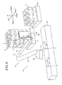
Fig. 2A is a perspective view schematically showing a po sture of a hand when a plastic container is kept in an upwardl y-oriented posture, andFig. 2B is a perspective view schemat ically showing a posture of the hand when a plastic container is kept in a downwardly-oriented posture. -
Fig. 3 is a side view schematically showing a configurat ion of the hand. -
Fig. 4 is a plan view schematically showing the configur ation of the hand. -
Fig. 5 to Fig. 9 are schematic diagrams for explaining o ne example of operations of a robot and the hand performed und er the control of a controller. -
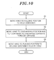
Fig. 10 is a flow chart for explaining robot control met hod. - An embodiment of the present disclosure will now be desc ribed with reference to the drawings. If annotations "front" , "rear", "left", "right", "upper" and "lower" exist in the d rawings, the terms "front", "rear", "left", "right", "upper" and "lower" used in the description of the subject specificat ion indicate the directions designated by the annotations.
- Referring first to
Figs. 1 to 4 , description will be mad e on the overall configuration of a robot system according to the present embodiment and the components thereof. - As shown in
Fig. 1 , therobot system 1 of the present em bodiment includes a holding-side pallet (a holding-side conta iner storage location) 30, arobot 10, acontroller 20, a conv eyor (a transportation unit) 40 and a placing-side pallet (a placing-side container storage location) 50. The holding-sid e pallet 30, theconveyor 40 and the placing-side pallet 50 ar e at least partially arranged within an effective operation r ange of therobot 10. - A plurality of general-purpose box-shaped (substantiall y rectangular parallelepiped) plastic containers 2 (hereinaft er briefly referred to as "
containers 2"), each of which rece ives one or more articles (contents) 3, is stacked and placed on the holding-side pallet 30. The stacked state (the positi on, orientation, quantity, stage number, column number, etc.) of thecontainers 2 on the holding-side pallet 30 is not limi ted to the one shown inFig. 1 . - Examples of the
articles 3 include, but are not limited to, agricultural products (crops) such as vegetables and frui ts, marine products such as seafood and seaweeds, industrial goods, components and raw materials. - The upper surface portion of the
container 2 facing upwa rd in the stacked state becomes an opening 2o through whichar ticles 3 can be put in and taken out of thecontainer 2. Thro ugh-holes surface portio ns container 2 facing frontward, rear ward, leftward and rightward in a stacked state, respectively . In the following description, theside surface portions holes - The
robot 10 includes abase block 11, arotator 12 and anarm 13. - The
base block 11 is fixed upright to an installation po rtion for the robot 10 (e.g., a floor (not shown)) by anchor b olts (not shown). Alternatively, thebase block 11 may be fix ed to a portion other than the floor (e.g., a ceiling or a wal l (not shown)). - The
rotator 12 is connected to the upper end portion of thebase block 11 so as to rotate about a rotation axis Ax1 su bstantially perpendicular to the fixing surface (the bottom p ortion in the illustrated example) of thebase block 11. By t he operation of an actuator Ac1 provided in (or adjacent to) a joint between therotator 12 and thebase block 11, the rotat or 12 is rotationally driven about the rotation axis Ax1 with respect to the upper end portion of thebase block 11. - The
arm 13 includes afirst structure 14, asecond struc ture 15, athird structure 16, afourth structure 17 and afif th structure 18, which are arranged from the base end side (th e side of the rotator 12) to the opposite tip end side. - The
first structure 14 is connected to the upper end por tion of therotator 12 so as to rotate about a rotation axis A x2 substantially perpendicular to the rotation axis Ax1. By the operation of an actuator Ac2 provided in (or adjacent to) a joint between thefirst structure 14 and therotator 12, thefirst structure 14 is rotationally driven about the rotation axis Ax2 with respect to the upper end portion of therotator 12. - The
second structure 15 is connected to the tip end port ion of thefirst structure 14 so as to rotate about a rotation axis Ax3 substantially parallel to the rotation axis Ax2. By the operation of an actuator Ac3 provided in (or adjacent to) a joint between thesecond structure 15 and thefirst structu re 14, thesecond structure 15 is rotationally driven about t he rotation axis Ax3 with respect to the tip end portion of th efirst structure 14. - The
third structure 16 is connected to the tip end porti on of thesecond structure 15 so as to rotate about a rotation axis Ax4 substantially perpendicular to therotation axis Ax 3. By the operation of an actuator Ac4 provided in (or adjace nt to) a joint between thethird structure 16 and the second structure 15, thethird structure 16 is rotationally driven ab out the rotation axis Ax4 with respect to the tip end portion of thesecond structure 15. - The
fourth structure 17 is connected to the tip end port ion of thethird structure 16 so as to rotate about a rotation axis Ax5 substantially perpendicular to the rotation axis Ax 4. By the operation of an actuator Ac5 provided in (or adjace nt to) a joint between thefourth structure 17 and the third structure 16, thefourth structure 17 is rotationally driven a bout the rotation axis Ax5 with respect to the tip end portion of thethird structure 16. - The
fifth structure 18 is connected to the tip end porti on of thefourth structure 17 so as to rotate about a rotation axis Ax6 substantially perpendicular to the rotation axis Ax 5. By the operation of an actuator Ac6 provided in (or adjace nt to) a joint between thefifth structure 18 and thefourth s tructure 17, thefifth structure 18 is rotationally driven ab out the rotation axis Ax6 with respect to the tip end portion of thefourth structure 17. - A servo motor and a speed reducer are included in each o f the actuators Ac1 to Ac6 of the
robot 10. A motor having an output shaft (a driving shaft) and a position detector are in cluded in the servo motor. The rotation position information indicating the rotation position of the motor of each of the actuators Ac1 to Ac6, as a signal generated from position det ector, is outputted to thecontroller 20 at every predetermin ed calculation period. - A hand 60 (a robot hand) capable of holding the
containe r 2 is attached to the tip end portion of the fifth structure 18 (namely, the tip end portion of the robot 10). Thehand 60 is rotated about the rotation axis Ax6 by the rotational oper ation of thefifth structure 18 about the rotation axis Ax6, w hich is caused by the operation of the actuator Ac6. As shown inFigs. 2A and2B , thehand 60 can tilt thecontainer 2 by m aking rotation about the rotation axis Ax6 while holding thecontainer 2. More specifically, by making rotation about the rotation axis Ax6 while holding thecontainer 2, thehand 60 can switch the posture of thecontainer 2 to an upward posture in which the opening 2o is oriented upward (a posture shown i nFig. 2A ) and a downward posture in which the opening 2o is o riented more downward than a horizontal plane (a posture show n inFig. 2B ). - As shown in
Figs. 3 and4 , thehand 60 includes aflat b racket 61, aflat plate 62, aholding mechanism 63 which holds one side surface portion 4 of thecontainer 2, and a chute 64 (seeFigs. 1 to 2B ). - The
bracket 61 is fixed to the tip end portion of thefi fth structure 18 and is rotated about the rotation axis Ax6 as thefifth structure 18 rotates about the rotation axis Ax6. - The
plate 62 is fixed to anouter edge portion 61a ofth e bracket 61 such that theplate 62 extends in the same direct ion as the rotation axis Ax6 (namely, parallel to the rotatio n axis Ax6). Theplate 62 is formed longer than thecontainer 2 in the height direction of thecontainer 2 assuming the upw ard posture (in the up-down direction inFig. 3 ) (seeFig. 2A ) . That is to say, the longitudinal dimension L of the plate 6 2 is larger than the height direction dimension H of theconta iner 2 assuming the upward posture. Theplate 62 is arranged so that, when thecontainer 2 held by the holdingmechanism 63 is tilted, particularly when the posture of thecontainer 2 i s switched to the downward posture, theplate 62 can be positi oned below the container 2 (seeFig. 2B ). - The holding
mechanism 63 includes aguide rail 631 and a pair ofsliders 632. - The
guide rail 631 is fixed to onesurface 62a (the righ t surface inFig. 4 ) of theplate 62 so as to extend in the di rection of the rotation axis Ax6. - The
sliders 632 engage with theguide rail 631 so that t hey can perform an operation (an opening/closing operation) b y which thesliders 632 are moved away from or toward each oth er along the direction of the rotation axis Ax6. Thesliders 632 are opened and closed by the operation of the actuator Ac7 provided in a suitable portion of the hand 60 (at the side of onesurface 62a of theplate 62 in the illustrated example). Examples of the actuator Ac7 include, but are not limited to, a solenoid, a servo motor, a hydraulic cylinder, an air cylin der and an electric cylinder. - A pair of
hooks 633 capable of being pressed against the longitudinal opposite edges (the front and rear edges in Fig s. 3 and 4) of the through-hole 5 formed in the side surface p ortion 4 of thecontainer 2 is fixed to thesliders 632. Thehooks 633 are moved away from or toward each other along the d irection of the rotation axis Ax6 by the open/closing operati on of thesliders 632 caused by the operation of the actuator Ac7. Thetip end portions 633a of thehooks 633 protrude outw ard beyond theother surface 62b (the left surface inFig. 4 ) of theplate 62 through the through-hole 62c formed in thepla te 62 so that thetip end portions 633a extend away from the c enter of theplate 62 in the direction of the rotation axis Ax 6. - In the
holding mechanism 63 described above, upon drivin g the actuator Ac7, the driving power thereof is transmitted to thesliders 632 via a suitable power transmission mechanis m (not shown), whereby thesliders 632 are opened or closed. By the opening/closing operation of thesliders 632, the hook s 633 are moved away from or toward each other along the direc tion of the rotation axis Ax6. As a result, the holdingmech anism 63 can hold or release the side surface portion 4 of thecontainer 2. Specifically, thehooks 633 are moved toward ea ch other. In this state, thetip end portions 633a of thehoo ks 633 are moved from the outside of thecontainer 2 to the in side thereof through the through-hole 5 of the side surface p ortion 4. Thereafter, thehooks 633 are moved away from each other. Thus, thehooks 633 are brought into contact with, and pressed against, the longitudinal opposite edges of the thro ugh-hole 5. Thetip end portions 633a are made to engage with the longitudinal opposite edges of the through-hole 5 in the inside of thecontainer 2. Consequently, the holdingmechani sm 63 can hold the side surface portion 4 of thecontainer 2. When theholding mechanism 63 releases the side surface port ion 4 of thecontainer 2, thehooks 633 are moved toward each other. Thetip end portions 633a of thehooks 633 are moved f rom the inside of thecontainer 2 to the outside of the contai ner 2 through the through-hole 5 of the side surface portion 4 . Consequently, the holdingmechanism 63 can release the sid e surface portion 4 of thecontainer 2. - Portions of the
holding mechanism 63 other than thetip end portions 633a of thehooks 633 and the actuator Ac7 are no t shown in the figures other thanFig. 4 . - The
chute 64 is made of stainless steel. On theother s urface 62b of theplate 62, thechute 64 is removably attached to aportion 62p (hereinafter sometimes referred to as "prot rusionportion 62p") of theplate 62 arranged at one side of t he tipend portions 633a of the hooks 633 (at the upper side i nFig. 3 ) in the direction substantially perpendicular to the rotation axis Ax6. Thechute 64 may be made of a material ot her than stainless steel. Thechute 64 is provided withwall portions 64a at the opposite ends thereof in the direction of the rotation axis Ax6. When the posture of thecontainer 2, t he side surface portion 4 of which is held by the holdingmech anism 63, is switched to the downward posture, thearticles 3 existing within thecontainer 2 can be slid down along thechu te 64. Thewall portions 64a of thechute 64 are not shown in the figures other thanFigs. 2B and3 . - Referring again to
Fig. 1 , thecontroller 20 includes at least one computer having, e.g., an arithmetic unit, a stora ge unit and an input unit. Thecontroller 20 is connected to the actuators Ac1 to Ac6 provided in therobot 10 and the actu ator Ac7 provided in thehand 60 so that thecontroller 20 can make communication with the actuators Ac1 to Ac6 and the actu ator Ac7. Thecontroller 20 controls the operations of the ro bot 10 (specifically, therotator 12 and the first tofifth st ructures 14 to 18 of the arm 13) and the hand 60 (specifically , the holding mechanism 63) by controlling the operation of t he actuators Ac1 to Ac7. Description will be made later in mo re detail on the operations of therobot 10 and thehand 60 pe rformed under the control of thecontroller 20. - The
conveyor 40 conveys thearticles 3 discharged out of thecontainer 2 along a specified conveyance route (see arro ws A1, A2 and A3 inFig. 1 ). - The
containers 2 which become empty as a result of the d ischarge of the articles 3 (hereinafter sometimes referred to as "empty containers 2") are placed and stacked on the placin g-side pallet 50. The stacked state (the position, orientati on, quantity, stage number, row number, etc.) of thecontaine rs 2 on the placing-side pallet 50 is not limited to the one s hown inFig. 1 . - Referring next to
Figs. 5 to 10 , description will be mad e on one example of the operations of therobot 10 and thehan d 60 performed under the control of thecontroller 20. In Fig s. 5 to 9, one example of the operations of therobot 10 and t he hand 60 performed under the control of thecontroller 20 is illustrated in a chronological order ofFig. 5 ,Fig. 6 ,Fig. 7 ,Fig. 8 andFig. 9 . - As shown in
Fig. 5 , therotator 12 and the first to fifth structures 14 to 18 of thearm 13 are appropriately driven u nder the control of thecontroller 20. As a result, therobot 10 moves thehand 60 to a holding position on the holding-sid e pallet 30 corresponding to a location of a holdingtarget co ntainer 2. Then, the holdingmechanism 63 is appropriately d riven under the control of thecontroller 20. Thus, thehand 60 holds the side surface portion 4 (theside surface portion 4d in the illustrated example) of the holdingtarget containe r 2 using the holding mechanism 63 (step S1 inFig. 10 ). - Thereafter, as shown in
Fig. 6 , therotator 12 and the f irst tofifth structures 14 to 18 of thearm 13 are appropriat ely driven under the control of thecontroller 20. As a resul t, therobot 10 moves thehand 60, which holds sidesurface po rtion 4d of thecontainer 2, toward a discharging position ne ar the upstream end of the conveyance route of thearticles 3. - Then, if the
hand 60 is moved to the discharging positio n as shown inFig. 7 , therotator 12 and the first tofifth st ructures 14 to 18 of thearm 13 are appropriately driven under the control of thecontroller 20. As a result, therobot 10 rotates thehand 60, which holdsside surface portion 4d ofth e container 2, in one direction (in the clockwise direction i n this example) about the rotation axis Ax6. Consequently, t he posture of thecontainer 2 is switched from the upward post ure to the downward posture. Thearticles 3 of thecontainer 2 are taken out from the opening 2o and are slid down alongth e chute 64. Thus, thearticles 3 are discharged onto the conv eyor 40 (step S2 inFig. 10 ). - Thereafter, if all the
articles 3 contained within thec ontainer 2 are discharged onto theconveyor 40 as shown inFig . 8 , therotator 12 and the first tofifth structures 14 to 18 of thearm 13 are appropriately driven under the control of t hecontroller 20. As a result, therobot 10 rotates thehand 60, which holdsside surface portion 4d of the container 2 (th e empty container 2), in the other direction (in the counterc lockwise direction in this example) about the rotation axis A x6. Consequently, the posture of theempty container 2 is ret urned from the downward posture to the upward posture. - Subsequently, as shown in
Fig. 9 , therotator 12 and the first tofifth structures 14 to 18 of thearm 13 are appropri ately driven under the control of thecontroller 20. As a res ult, therobot 10 moves thehand 60, which holdsside surface portion 4d of theempty container 2, to a placing position on the placing-side pallet 50 corresponding to a target placing location of theempty container 2. Then, the holdingmechani sm 63 is appropriately driven under the control of the contro ller 20. As a result, thehand 60 releases the sidesurface p ortion 4d of theempty container 2 held by the holdingmechani sm 63, thereby placing theempty container 2 in the target pla cing location (step S3 inFig. 10 ). - Thereafter, the
rotator 12 and the first to fifth struct ures 14 to 18 of thearm 13 are appropriately driven under the control of thecontroller 20. As a result, therobot 10 move s thehand 60 to a holding position corresponding to a locatio n of the next holdingtarget container 2 on the holding-side p allet 30. Then, the aforementioned operations are repeated. - In the present embodiment described above, under the con trol of the
controller 20, therobot 10 moves thehand 60, whi ch holds thecontainer 2, to the discharging position and the n rotates thehand 60 in one direction about the rotation axis Ax6. Consequently, the posture of thecontainer 2 is switche d from the upward posture to the downward posture, wherebyth e articles 3 contained within thecontainer 2 can be discharg ed from the opening 2o using the gravity. Thus, the work of d e-palletizing thecontainer 2 and the work of taking out the articles 3 from thecontainer 2 can be carried out through a se ries of operations. This makes it possible to effectively tr ansfer thearticles 3 contained within thecontainer 2. - In the present embodiment, among other things, the
hand 60 includes thebracket 61, theplate 62 and the holdingmecha nism 63. Theplate 62 is fixed to thebracket 61 so as to ext end in the same direction as the rotation axis Ax6. Theconta iner 2 is held by the holdingmechanism 63 arranged in thepla te 62. At this time, theplate 62 is arranged so that, when t he posture of thecontainer 2 is switched to the downward post ure, theplate 62 can be positioned below thecontainer 2. As a consequence, when the posture of thecontainer 2 is switche d to the downward posture, theplate 62 can support thecontai ner 2, thereby stabilizing the posture of thecontainer 2.Th e plate 62 is formed longer than thecontainer 2 in the height direction of thecontainer 2. Therefore, when the posture of thecontainer 2 is switched to the downward posture, the chut e 64 can be arranged in theprotrusion portion 62p of theplat e 62. - In the present embodiment, among other things, the
hand 60 includes thechute 64 along which thearticles 3 contained within thecontainer 2 are slid down. Therefore, when the pos ture of thecontainer 2 is switched to the downward posture, i t is possible to smoothly discharge thearticles 3. Since thechute 64 is made of stainless steel, it is possible to facili tate sliding of thearticles 3 and to prevent generation of ru st even when thechute 64 is washed with water. Moreover, thechute 64 can be easily replaced due to the removable attachme nt thereof. This makes it possible to effectively perform a w ork even if thearticles 3 are diverse. - In the present embodiment, among other things, the
plate 62 for holding thecontainer 2 is fixed to the outer edge portion 61a of thebracket 61. Therefore, as compared with a cas e where theplate 62 is arranged in a portion other than the outer edge portion 61a of the bracket 61 (e.g., in a central po rtion of the bracket 61), it is possible to enable the plate 6 2 to reach thecontainer 2 positioned farther away. This make s it possible to expand the operation range of therobot 10. - In the present embodiment, among other things, the holdi ng
mechanism 63 of thehand 60 holds thecontainer 2 as a gene ral-purpose plastic container which has been used by workers. - Thus, there is no need to use an improved special plastic co ntainer. This makes it possible to reduce the cost otherwise required in preparing a special plastic container.
- The present disclosure is not limited to the aforementio ned embodiment but may be modified in many different forms wi thout departing from the spirit and technical concept of the present disclosure. Modified examples will now be described one after another.
- In the embodiment described above, the
hand 60 is config ured to hold onecontainer 2 at a time. However, the present disclosure is not limited thereto. Thehand 60 may be configu red to hold a plurality ofcontainers 2 at a time. - While not specifically shown, according to the
hand 60 o f the present modified example, theplate 62 fixed to the outer edge portion 61a of thebracket 61 to extend in the same dir ection as the rotation axis Ax6 has a length large enough to e nable the plate to hold a plurality of (e.g., three)containe rs 2 disposed along the direction of the rotation axis Ax6 (e. g., a length larger than the dimension of the plurality ofcon tainers 2 in the direction of the rotation axis Ax6). Thepla te 62 of the present modified example is provided with a holdi ngmechanism 63 for holding one side surface portion 4 of each of thecontainers 2. The holdingmechanism 63 of the present modified example includes a plurality of slide mechanisms, e ach of which is formed of a guide rail and a pair of sliders.
A pair of hooks is fixed at one end to each of the pairs of s liders. In theholding mechanism 63 of the present modified e xample, upon driving one or more actuators provided in suitab le portions of thehand 60, the driving power thereof is trans mitted to the respective pairs of sliders via a suitable powe r transmission mechanism, whereby the respective pairs of sli ders are opened or closed. By the opening/closing operations of the respective pairs of sliders, the respective pairs of h ooks are moved away from or toward each other along the direct ion of the rotation axis Ax6. As a result, the holdingmechan ism 63 of the present modified example can hold or release one side surface portion 4 of each of thecontainers 2. - According to the present modified example, it is possibl e to obtain the same effects as in the aforementioned embodim ent. In the present modified example, the
containers 2 are no t held in thebracket 61 but in theplate 62. It is therefore possible to obtain the following effects. In case where a pl urality ofcontainers 2 is held in thebracket 61 at a time, t here is likelihood that, when the posture of each of theconta iners 2 is switched to the downward posture by rotating theha nd 60 about the rotation axis Ax6, the heights of the respecti vecontainers 2 with respect to the discharging position may differ from one another and thearticles 3 contained within t hecontainer 2 having a higher position may be damaged due to the falling shock. In contrast, if thecontainers 2 are held in theplate 62 extending in the same direction as the rotatio n axis Ax6, therespective containers 2 can be kept at the sam e height with respect to the discharging position when the po sture of each of thecontainers 2 is switched to the downward posture by rotating thehand 60 about the rotation axis Ax6. This makes it possible to discharge thearticles 3 contained within thecontainers 2 with no damage. Thus, the work of de-palletizing the plurality ofcontainers 2 and the work of tak ing out thearticles 3 from therespective containers 2 can be carried out through a series of operations. It is therefore possible to realize therobot system 1 capable of effectively transferring thearticles 3 contained within therespective containers 2. - In the present modified example, the
plate 62 has a leng th large enough to enable the plate to hold a plurality ofcon tainers 2 disposed along the direction of the rotation axis A x6. The holdingmechanism 63 holds one side surface portion 4 of each of thecontainers 2. Thus, the work of de-palletizin g the plurality ofcontainers 2 at a time and the work of taki ng out thearticles 3 from therespective containers 2 can be carried out through a series of operations. It is therefore p ossible to effectively transfer thearticles 3 contained with in therespective containers 2 and to significantly reduce th e tact time. - In the embodiment described above, the
chute 64 is fixed to theprotrusion portion 62p of theplate 62. However, the present disclosure is not limited thereto. If thearticles 3 can be smoothly discharged depending on the nature thereof, t hechute 64 may be omitted. In this case, theprotrusion port ion 62p of theplate 62 serves as a discharge path of thearti cles 3 when the posture of thecontainer 2 is switched to the downward posture. - In the embodiment described above, the
plate 62 is fixed to theouter edge portion 61a of thebracket 61. However, th e present disclosure is not limited thereto. Theplate 62 may be fixed to a portion other than theouter edge portion 61a o f the bracket 61 (e.g., a central portion of the bracket 61). - In the embodiment described above, the
container 2 is he ld by the holdingmechanism 63 provided in theplate 62 fixed to thebracket 61. Thus, thecontainer 2 is held in theplate 62. However, the present disclosure is not limited thereto. For example, theplate 62 may not be provided in thebracket 61 and the holding mechanism may be provided in thebracket 61 . By holding thecontainer 2 with the holding mechanism, thecontainer 2 may be held in thebracket 61. - In the embodiment described above, the
robot 10 rotates thehand 60 about the rotation axis Ax6 to thereby switch the posture of thecontainer 2 to the downward position. Thus,th e articles 3 contained within thecontainer 2 are discharged from the opening 2o onto theconveyor 40. However, the presen t disclosure is not limited thereto. For example, therobot 1 0 may rotate thehand 60 about the rotation axis Ax6 to thereb y tilt thecontainer 2 so that the opening 2o can be substanti ally horizontally inclined. Thus, thearticles 3 contained w ithin thecontainer 2 may be discharged from the opening 2o on to theconveyor 40. - In the embodiment described above, the holding and relea sing of the
container 2 is performed by the holdingmechanism 63 arranged in thehand 60 and provided with theguide rail 63 1, thesliders 632 and thehooks 633. However, the shape and configuration of the holding mechanism and the shape and conf iguration of the hand are not particularly limited as long as they can perform the holding and releasing of thecontainer 2 - In the embodiment described above, the
container 2 conta ining thearticles 3 is placed on the holding-side pallet 30. However, the present disclosure is not limited thereto. Thecontainer 2 may be placed in a location other than the holding -side pallet 30 (e.g., a floor or a suitable conveying surfac e of the conveyor). In this case, the location other than the holding-side pallet 30 corresponds to the holding-side conta iner storage location. - In the embodiment described above, the
robot 10 discharg es to thearticles 3 contained within thecontainer 2 onto theconveyor 40. However, the present disclosure is not limited thereto. Thearticles 3 contained within thecontainer 2 may be discharged to a location other than the conveyor 40 (e.g., into a suitable container). - In the embodiment described above, the
articles 3 discha rged from thecontainer 2 are conveyed by theconveyor 40. Ho wever, the present disclosure is not limited thereto. The ar ticles 3 discharged from thecontainer 2 may be transported b y a transportation unit other than the conveyor 40 (e.g., a li ft). - In the embodiment described above, the
robot 10 places t heempty container 2 on the placing-side pallet 50. However, the present disclosure is not limited thereto. Theempty con tainer 2 may be placed on a location other than the placing-si de pallet 50 (e.g., on theconveyor 40 or the floor). In this case, the location other than the placing-side pallet 50 cor responds to the placing-side container storage location. - In the embodiment described above, the
container 2 conta ining thearticles 3 is formed of a general-purpose plastic c ontainer. However, the present disclosure is not limited the reto. Thecontainer 2 may be formed of a special plastic cont ainer. - In the embodiment described above, the
articles 3 are co ntained within thecontainer 2. However, the present disclos ure is not limited thereto. Thearticles 3 may be contained w ithin a receptacle other than the container 2 (e.g., a cardbo ard box). - In the embodiment described above, description has been made on an example in which the
articles 3 are solid bodies. However, the contents of thecontainer 2 are not limited to th e solid bodies but may be a fluid such as a liquid or the like or a powder, which can be contained within the container. - In the aforementioned embodiment, the
robot 10 is formed of a robot having six drive shafts. However, the present dis closure is not limited thereto. Therobot 10 may be formed of a robot having five or less drive shafts or a robot having se ven or more drive shafts. In the aforementioned embodiment, therobot 10 is formed of a so-called single-arm robot. Howev er, the present disclosure is not limited thereto. Therobot 10 may be formed of a multi-arm robot. - In addition to the above description, the embodiment and the modified examples described above may be appropriately c ombined.
- While not specifically illustrated, the embodiment and the modified examples described above may be added with many different changes without departing from the spirit and scope of the present disclosure.
Claims (10)
- A robot hand attached to a robot having one or more driv e shafts and configured to hold a container having an opening through which contents are put in and taken out of the contain er, wherein the robot hand is configured to move to a holding position to hold the container, to move to a discharging posi tion to tilt the container to discharge the contents through the opening, and to move to a placing position to release the container.
- A robot comprising:one or more drive shafts; andthe robot hand recited in claim 1.
- A robot system, comprising:the robot recited in claim 2;a controller for controlling operations of the robot and the robot hand,wherein the controller is configured to perform an opera tion of moving the robot hand to the holding position to hold the container, an operation of moving the robot hand to the di scharging position and tilting the container to discharge the contents through the opening, and an operation of moving the robot hand to the placing position to release the container h eld by the robot hand.
- The robot system of claim 3, wherein the hand includes a bracket provided at a tip end of the robot so as to rotate ab out a rotation axis, a plate fixed to the bracket so as to ext end in the same direction as the rotation axis, and a holding mechanism provided in the plate and configured to hold the co ntainer.
- The robot system of claim 4, wherein the plate is formed longer than the container in a height direction of the contai ner and is arranged such that, when the container is tilted, t he plate is positioned below the container.
- The robot system of claim 4 or 5, wherein the hand furth er includes a chute provided in the plate and configured to al low the contents to slide down along the chute when the contai ner is tilted.
- The robot system of any one of claims 4 to 6, wherein th e plate has a length large enough to enable the plate to hold a plurality of containers disposed along a direction of the r otation axis, the holding mechanism configured to hold one si de surface portion of each of the plurality of containers.
- The robot system of any one of claims 4 to 7, wherein th e plate is fixed to an outer edge portion of the bracket.
- The robot system of any one of claims 4 to 8, further co mprising:a holding-side container storage location arranged with in an operation range of the robot and configured to store the container containing the contents, a transportation unit con figured to transport the contents, and a placing-side contain er storage location arranged within the operation range of th e robot and configured to store the container from which the c ontents have been discharged.
- A robot control method for controlling a robot which inc ludes one or more drive shafts and to which is attachable a ha nd configured to hold a container having an opening through w hich contents are put in and taken out of the container, the m ethod comprising:moving the hand to a holding position to hold the contai ner;moving the hand to a discharging position and tilting th e container to discharge the contents through the opening; an dmoving the hand to a placing position to release the con tainer held by the hand.
Applications Claiming Priority (1)
| Application Number | Priority Date | Filing Date | Title |
|---|---|---|---|
| JP2012253580A JP5717007B2 (en) | 2012-11-19 | 2012-11-19 | Robot system, robot hand, robot |
Publications (1)
| Publication Number | Publication Date |
|---|---|
| EP2732926A1 true EP2732926A1 (en) | 2014-05-21 |
Family
ID=49517300
Family Applications (1)
| Application Number | Title | Priority Date | Filing Date |
|---|---|---|---|
| EP13190815.4A Withdrawn EP2732926A1 (en) | 2012-11-19 | 2013-10-30 | Robot system, robot hand, robot, and a robot control method |
Country Status (6)
| Country | Link |
|---|---|
| US (1) | US20140142751A1 (en) |
| EP (1) | EP2732926A1 (en) |
| JP (1) | JP5717007B2 (en) |
| CN (1) | CN103817702A (en) |
| BR (1) | BR102013029819A2 (en) |
| IN (1) | IN2013CH05253A (en) |
Cited By (8)
| Publication number | Priority date | Publication date | Assignee | Title |
|---|---|---|---|---|
| CN106466821A (en) * | 2015-08-19 | 2017-03-01 | 通用汽车环球科技运作有限责任公司 | Parts fastening assembly, component system and positioning and the method for securing part |
| US9971336B2 (en) | 2015-08-19 | 2018-05-15 | GM Global Technology Operations LLC | Part holding assembly, an assembly system and a method of locating and securing a part |
| US10112307B2 (en) | 2014-08-25 | 2018-10-30 | GM Global Technology Operations LLC | Part holding assembly, an assembly system and a method of positioning a first part |
| US20190047787A1 (en) * | 2017-08-08 | 2019-02-14 | Alert Innovation Inc. | Universal gripper for tote and sub-tote transport |
| DE102019203435A1 (en) * | 2019-03-13 | 2020-09-17 | Volkswagen Aktiengesellschaft | Method for removing components arranged in layers in a transport container and device for carrying out the method |
| EP3730434A1 (en) * | 2019-04-25 | 2020-10-28 | Stöcklin Logistik AG | Method and system for picking goods in stackable piece good containers on pallets in a pallet storage on a target pallet |
| WO2021198565A3 (en) * | 2020-03-31 | 2021-12-09 | Shipmypacket Oy | Attachment interface, automated storage system, and gripper |
| US12091205B2 (en) | 2019-02-06 | 2024-09-17 | Marel Salmon A/S | System for opening and emptying a box with a lid |
Families Citing this family (15)
| Publication number | Priority date | Publication date | Assignee | Title |
|---|---|---|---|---|
| CN104370105B (en) * | 2014-06-17 | 2017-01-25 | 微密冲压件(无锡)有限公司 | Quick hard disk cover collecting system |
| JP6774871B2 (en) * | 2016-12-26 | 2020-10-28 | 川崎重工業株式会社 | Sheet-shaped food removal mechanism and sheet-shaped food removal method using it |
| CA3083095A1 (en) * | 2017-11-21 | 2019-05-31 | Fulfil Solutions, Inc. | Product handling and packaging system |
| EP3781491B1 (en) * | 2018-04-19 | 2023-04-12 | Compagnie Generale Des Etablissements Michelin | System for processing products recovered for reuse |
| CN117783557A (en) | 2018-07-31 | 2024-03-29 | 安进公司 | Robotic inspection platform and method for container inspection using pattern recognition |
| JP6994176B2 (en) * | 2019-09-19 | 2022-01-14 | 株式会社安川電機 | Transport system, transport method, robot |
| LV15561A (en) * | 2019-10-03 | 2021-04-20 | Roboeatz, Sia | Robotic cooking system |
| KR102137935B1 (en) * | 2020-02-19 | 2020-07-27 | 씨제이제일제당(주) | System for Opening of Packaging Box |
| IT202000011065A1 (en) * | 2020-05-14 | 2021-11-14 | SYSTEM AND METHOD OF EMPTYING A BASKET | |
| CN113772403B (en) * | 2020-07-27 | 2023-05-30 | 北京京东乾石科技有限公司 | A device for removing objects from containers |
| NL2026455B1 (en) * | 2020-09-11 | 2022-05-12 | Moba Group Bv | A system and method for handling packaging units, and manipulator unit. |
| CN113401840B (en) * | 2021-06-16 | 2022-08-12 | 北京机械设备研究所 | Auxiliary assembling power-assisted arm of movable special vehicle |
| IT202100021458A1 (en) * | 2021-08-06 | 2023-02-06 | System Logistics S P A | Cassette pick-up device |
| EP4410713A1 (en) * | 2023-01-31 | 2024-08-07 | Siemens Logistics GmbH | Method and storage system for storing charge carriers |
| CN120659749A (en) * | 2023-01-31 | 2025-09-16 | 西门子物流有限责任公司 | Method and unloading system for unloading load carrier |
Citations (5)
| Publication number | Priority date | Publication date | Assignee | Title |
|---|---|---|---|---|
| JP2001089090A (en) | 1999-09-17 | 2001-04-03 | Okura Yusoki Co Ltd | Transferred cargo holding device |
| DE102005004229A1 (en) * | 2005-01-28 | 2006-08-17 | Hauni Primary Gmbh | Emptying tobacco containers |
| US20070069087A1 (en) * | 2005-09-29 | 2007-03-29 | Atec Pharmatechnik Gmbh | Device for lifting and rotating containers |
| US20070280812A1 (en) * | 2006-05-17 | 2007-12-06 | Axium Inc. | Tool and method for mixed palletizing/depalletizing |
| US20080274865A1 (en) * | 2005-09-23 | 2008-11-06 | Thomas Sturm | Processing Plant |
Family Cites Families (9)
| Publication number | Priority date | Publication date | Assignee | Title |
|---|---|---|---|---|
| JPS5347171A (en) * | 1976-10-12 | 1978-04-27 | Shin Meiwa Ind Co Ltd | Apparatus for treating waste such as trash |
| JPH02205538A (en) * | 1989-01-25 | 1990-08-15 | Seibu Electric & Mach Co Ltd | Apparatus for taking out object |
| US5246327A (en) * | 1991-07-12 | 1993-09-21 | Eastman Kodak Company | Apparatus and method for precisely dispensing solid materials |
| JP2893567B2 (en) * | 1993-12-24 | 1999-05-24 | 極東開発工業株式会社 | Automatic container reversing device |
| JPH11300539A (en) * | 1998-04-22 | 1999-11-02 | Hirata Corp | Supplying and discharging device of vessel |
| JP3602817B2 (en) * | 2001-10-24 | 2004-12-15 | ファナック株式会社 | Food laying robot and food laying device |
| JP2007296607A (en) * | 2006-04-28 | 2007-11-15 | Nissan Motor Co Ltd | Component pickup apparatus and component pickup method |
| JP2009285753A (en) * | 2008-05-28 | 2009-12-10 | Shibuya Kogyo Co Ltd | Robot control system |
| JP5746846B2 (en) * | 2010-11-04 | 2015-07-08 | 賀夫 井上 | Dry noodle wire charging device |
-
2012
- 2012-11-19 JP JP2012253580A patent/JP5717007B2/en not_active Expired - Fee Related
-
2013
- 2013-10-30 EP EP13190815.4A patent/EP2732926A1/en not_active Withdrawn
- 2013-11-08 US US14/074,719 patent/US20140142751A1/en not_active Abandoned
- 2013-11-14 IN IN5253CH2013 patent/IN2013CH05253A/en unknown
- 2013-11-18 CN CN201310576826.8A patent/CN103817702A/en active Pending
- 2013-11-19 BR BR102013029819-0A patent/BR102013029819A2/en not_active IP Right Cessation
Patent Citations (5)
| Publication number | Priority date | Publication date | Assignee | Title |
|---|---|---|---|---|
| JP2001089090A (en) | 1999-09-17 | 2001-04-03 | Okura Yusoki Co Ltd | Transferred cargo holding device |
| DE102005004229A1 (en) * | 2005-01-28 | 2006-08-17 | Hauni Primary Gmbh | Emptying tobacco containers |
| US20080274865A1 (en) * | 2005-09-23 | 2008-11-06 | Thomas Sturm | Processing Plant |
| US20070069087A1 (en) * | 2005-09-29 | 2007-03-29 | Atec Pharmatechnik Gmbh | Device for lifting and rotating containers |
| US20070280812A1 (en) * | 2006-05-17 | 2007-12-06 | Axium Inc. | Tool and method for mixed palletizing/depalletizing |
Cited By (15)
| Publication number | Priority date | Publication date | Assignee | Title |
|---|---|---|---|---|
| US10112307B2 (en) | 2014-08-25 | 2018-10-30 | GM Global Technology Operations LLC | Part holding assembly, an assembly system and a method of positioning a first part |
| CN106466821B (en) * | 2015-08-19 | 2019-05-21 | 通用汽车环球科技运作有限责任公司 | The method of components fastening assembly, component system and positioning and securing part |
| CN106466821A (en) * | 2015-08-19 | 2017-03-01 | 通用汽车环球科技运作有限责任公司 | Parts fastening assembly, component system and positioning and the method for securing part |
| US9971336B2 (en) | 2015-08-19 | 2018-05-15 | GM Global Technology Operations LLC | Part holding assembly, an assembly system and a method of locating and securing a part |
| US10112666B2 (en) | 2015-08-19 | 2018-10-30 | GM Global Technology Operations LLC | Part holding assembly, an assembly system and a method of locating and securing a part |
| US10815057B2 (en) * | 2017-08-08 | 2020-10-27 | Alert Innovation Inc. | Universal gripper for tote and sub-tote transport |
| WO2019032651A1 (en) * | 2017-08-08 | 2019-02-14 | Alert Innovation Inc. | UNIVERSAL PREACHER FOR THE TRANSPORT OF BAC AND SUB-BAC |
| US20190047787A1 (en) * | 2017-08-08 | 2019-02-14 | Alert Innovation Inc. | Universal gripper for tote and sub-tote transport |
| US11724877B2 (en) | 2017-08-08 | 2023-08-15 | Walmart Apollo, Llc | Universal gripper for tote and sub-tote transport |
| US12091205B2 (en) | 2019-02-06 | 2024-09-17 | Marel Salmon A/S | System for opening and emptying a box with a lid |
| DE102019203435A1 (en) * | 2019-03-13 | 2020-09-17 | Volkswagen Aktiengesellschaft | Method for removing components arranged in layers in a transport container and device for carrying out the method |
| DE102019203435B4 (en) * | 2019-03-13 | 2021-02-11 | Volkswagen Aktiengesellschaft | Method for removing components arranged in layers in a transport container and device for carrying out the method |
| EP3730434A1 (en) * | 2019-04-25 | 2020-10-28 | Stöcklin Logistik AG | Method and system for picking goods in stackable piece good containers on pallets in a pallet storage on a target pallet |
| WO2021198565A3 (en) * | 2020-03-31 | 2021-12-09 | Shipmypacket Oy | Attachment interface, automated storage system, and gripper |
| US12471707B2 (en) | 2020-03-31 | 2025-11-18 | Agora Networks Oy | Attachment interface, automated storage system, and gripper |
Also Published As
| Publication number | Publication date |
|---|---|
| US20140142751A1 (en) | 2014-05-22 |
| IN2013CH05253A (en) | 2015-04-24 |
| BR102013029819A2 (en) | 2014-10-21 |
| JP2014100757A (en) | 2014-06-05 |
| CN103817702A (en) | 2014-05-28 |
| JP5717007B2 (en) | 2015-05-13 |
Similar Documents
| Publication | Publication Date | Title |
|---|---|---|
| JP5717007B2 (en) | Robot system, robot hand, robot | |
| US11912499B2 (en) | Storage containers, bins and devices | |
| CN105492348B (en) | robot carton unloader | |
| RS53978B1 (en) | CIRCUIT DEVICE FOR ACCEPTANCE AND HANDLING OF GOODS | |
| CN115123719A (en) | automatic access system | |
| JP2019014003A (en) | Robot system and packaging system | |
| CN113070222B (en) | Robot and article letter sorting system | |
| JP5076153B2 (en) | Pallet feeding / discharging device and cell production system including the same | |
| JP2011073802A (en) | Chute and transfer system | |
| JP6943259B2 (en) | Packing system and packing method | |
| ES2298462T3 (en) | PROCEDURE AND DEVICE FOR PREPARING AUTOMATICALLY FOR THE EXPEDITION A PLURALITY OF ORDERS IN AN INDIVIDUAL CARTON BOX, LAYERS OR IN A PLURALITY OF THE SAME. | |
| JP2024060714A (en) | Robot Hand | |
| CA3000941C (en) | Picking systems and methods | |
| WO2024110679A1 (en) | A method and system for gathering a number of articles with a target total weight |
Legal Events
| Date | Code | Title | Description |
|---|---|---|---|
| PUAI | Public reference made under article 153(3) epc to a published international application that has entered the european phase |
Free format text: ORIGINAL CODE: 0009012 |
|
| 17P | Request for examination filed |
Effective date: 20131030 |
|
| AK | Designated contracting states |
Kind code of ref document: A1 Designated state(s): AL AT BE BG CH CY CZ DE DK EE ES FI FR GB GR HR HU IE IS IT LI LT LU LV MC MK MT NL NO PL PT RO RS SE SI SK SM TR |
|
| AX | Request for extension of the european patent |
Extension state: BA ME |
|
| R17P | Request for examination filed (corrected) |
Effective date: 20141027 |
|
| RBV | Designated contracting states (corrected) |
Designated state(s): AL AT BE BG CH CY CZ DE DK EE ES FI FR GB GR HR HU IE IS IT LI LT LU LV MC MK MT NL NO PL PT RO RS SE SI SK SM TR |
|
| STAA | Information on the status of an ep patent application or granted ep patent |
Free format text: STATUS: THE APPLICATION IS DEEMED TO BE WITHDRAWN |
|
| 18D | Application deemed to be withdrawn |
Effective date: 20160503 |