EP2732925B1 - Impact tool - Google Patents
Impact tool Download PDFInfo
- Publication number
- EP2732925B1 EP2732925B1 EP13193209.7A EP13193209A EP2732925B1 EP 2732925 B1 EP2732925 B1 EP 2732925B1 EP 13193209 A EP13193209 A EP 13193209A EP 2732925 B1 EP2732925 B1 EP 2732925B1
- Authority
- EP
- European Patent Office
- Prior art keywords
- disposed
- switching
- mode
- housing
- hammer
- Prior art date
- Legal status (The legal status is an assumption and is not a legal conclusion. Google has not performed a legal analysis and makes no representation as to the accuracy of the status listed.)
- Active
Links
- 230000033001 locomotion Effects 0.000 claims description 28
- 238000009434 installation Methods 0.000 claims description 18
- 239000000314 lubricant Substances 0.000 claims description 10
- 238000007789 sealing Methods 0.000 claims description 6
- 230000002265 prevention Effects 0.000 claims description 5
- 230000001050 lubricating effect Effects 0.000 claims description 2
- 230000005540 biological transmission Effects 0.000 description 15
- 238000010276 construction Methods 0.000 description 10
- 239000000428 dust Substances 0.000 description 10
- 230000007935 neutral effect Effects 0.000 description 9
- 230000013011 mating Effects 0.000 description 4
- 230000000994 depressogenic effect Effects 0.000 description 2
- 238000005553 drilling Methods 0.000 description 2
- 230000000694 effects Effects 0.000 description 2
- 239000004519 grease Substances 0.000 description 2
- 238000012856 packing Methods 0.000 description 2
- 230000002093 peripheral effect Effects 0.000 description 2
- 229910000831 Steel Inorganic materials 0.000 description 1
- 238000003780 insertion Methods 0.000 description 1
- 230000037431 insertion Effects 0.000 description 1
- 230000004048 modification Effects 0.000 description 1
- 238000012986 modification Methods 0.000 description 1
- 230000001151 other effect Effects 0.000 description 1
- 239000010959 steel Substances 0.000 description 1
Images


Classifications
-
- B—PERFORMING OPERATIONS; TRANSPORTING
- B25—HAND TOOLS; PORTABLE POWER-DRIVEN TOOLS; MANIPULATORS
- B25D—PERCUSSIVE TOOLS
- B25D16/00—Portable percussive machines with superimposed rotation, the rotational movement of the output shaft of a motor being modified to generate axial impacts on the tool bit
- B25D16/006—Mode changers; Mechanisms connected thereto
-
- B—PERFORMING OPERATIONS; TRANSPORTING
- B25—HAND TOOLS; PORTABLE POWER-DRIVEN TOOLS; MANIPULATORS
- B25D—PERCUSSIVE TOOLS
- B25D17/00—Details of, or accessories for, portable power-driven percussive tools
- B25D17/26—Lubricating
-
- B—PERFORMING OPERATIONS; TRANSPORTING
- B25—HAND TOOLS; PORTABLE POWER-DRIVEN TOOLS; MANIPULATORS
- B25F—COMBINATION OR MULTI-PURPOSE TOOLS NOT OTHERWISE PROVIDED FOR; DETAILS OR COMPONENTS OF PORTABLE POWER-DRIVEN TOOLS NOT PARTICULARLY RELATED TO THE OPERATIONS PERFORMED AND NOT OTHERWISE PROVIDED FOR
- B25F5/00—Details or components of portable power-driven tools not particularly related to the operations performed and not otherwise provided for
- B25F5/001—Gearings, speed selectors, clutches or the like specially adapted for rotary tools
-
- B—PERFORMING OPERATIONS; TRANSPORTING
- B25—HAND TOOLS; PORTABLE POWER-DRIVEN TOOLS; MANIPULATORS
- B25D—PERCUSSIVE TOOLS
- B25D2216/00—Details of portable percussive machines with superimposed rotation, the rotational movement of the output shaft of a motor being modified to generate axial impacts on the tool bit
- B25D2216/0007—Details of percussion or rotation modes
- B25D2216/0023—Tools having a percussion-and-rotation mode
-
- B—PERFORMING OPERATIONS; TRANSPORTING
- B25—HAND TOOLS; PORTABLE POWER-DRIVEN TOOLS; MANIPULATORS
- B25D—PERCUSSIVE TOOLS
- B25D2217/00—Details of, or accessories for, portable power-driven percussive tools
- B25D2217/0096—Details of lubrication means
-
- B—PERFORMING OPERATIONS; TRANSPORTING
- B25—HAND TOOLS; PORTABLE POWER-DRIVEN TOOLS; MANIPULATORS
- B25D—PERCUSSIVE TOOLS
- B25D2250/00—General details of portable percussive tools; Components used in portable percussive tools
- B25D2250/255—Switches
-
- B—PERFORMING OPERATIONS; TRANSPORTING
- B25—HAND TOOLS; PORTABLE POWER-DRIVEN TOOLS; MANIPULATORS
- B25D—PERCUSSIVE TOOLS
- B25D2250/00—General details of portable percussive tools; Components used in portable percussive tools
- B25D2250/345—Use of o-rings
-
- B—PERFORMING OPERATIONS; TRANSPORTING
- B25—HAND TOOLS; PORTABLE POWER-DRIVEN TOOLS; MANIPULATORS
- B25D—PERCUSSIVE TOOLS
- B25D2250/00—General details of portable percussive tools; Components used in portable percussive tools
- B25D2250/365—Use of seals
-
- B—PERFORMING OPERATIONS; TRANSPORTING
- B25—HAND TOOLS; PORTABLE POWER-DRIVEN TOOLS; MANIPULATORS
- B25D—PERCUSSIVE TOOLS
- B25D2250/00—General details of portable percussive tools; Components used in portable percussive tools
- B25D2250/371—Use of springs
- B25D2250/381—Leaf springs
-
- G—PHYSICS
- G05—CONTROLLING; REGULATING
- G05G—CONTROL DEVICES OR SYSTEMS INSOFAR AS CHARACTERISED BY MECHANICAL FEATURES ONLY
- G05G5/00—Means for preventing, limiting or returning the movements of parts of a control mechanism, e.g. locking controlling member
- G05G5/06—Means for preventing, limiting or returning the movements of parts of a control mechanism, e.g. locking controlling member for holding members in one or a limited number of definite positions only
-
- H—ELECTRICITY
- H01—ELECTRIC ELEMENTS
- H01H—ELECTRIC SWITCHES; RELAYS; SELECTORS; EMERGENCY PROTECTIVE DEVICES
- H01H9/00—Details of switching devices, not covered by groups H01H1/00 - H01H7/00
- H01H9/02—Bases, casings, or covers
- H01H9/06—Casing of switch constituted by a handle serving a purpose other than the actuation of the switch, e.g. by the handle of a vacuum cleaner
Definitions
- the teachings relate to an impact tool according to the preamble of claim 1, which performs a predetermined operation on a workpiece by at least linear movement of a tool bit in its axial direction.
- a power tool is known from US 2010/0084151 A1 .
- US 4,066,136 A discloses a torque and impulse transmitting machine.
- US 2002/0014343 A1 discloses a rotary switch for a hand-held power tool.
- Japanese non-examined laid-open Patent Publication No. 2002-292579 discloses a mode switching mechanism for switching an operation mode of a tool bit in an impact tool.
- This mode switching mechanism has an operating member which is turned by a user to switch the operation mode.
- the operating member is positioned and held in that angular position by a biasing member.
- the biasing member is formed by a leaf spring fastened to a housing and holds the operating member in the selected angular position by elastically engaging with a notch (recess) of the operating member.
- the biasing member is disposed outside of the housing and therefore affected by dust generated during hammering operation, which impairs its durability.
- an impact tool which performs a hammering operation on a workpiece by at least linear movement of a tool bit in an axial direction of the tool bit.
- the impact tool has a driving mechanism for driving the tool bit, a housing part forming a housing space in which at least part of the driving mechanism is disposed, and a switching member for switching a drive mode of the impact tool.
- the switching member has an operating member which is operated by a user for mode switching (selection), and a biasing member which is disposed between the operating member and the housing part and biases the operating member so as to hold it in a selected position. Further, the biasing member is disposed in the housing space.
- the manner of "switching the drive mode of the impact tool” represents, for example, the manner of switching the drive mode between a hammer mode in which a hammering operation is performed by striking movement of the tool bit and a hammer drill mode in which a hammer drill operation is performed by striking movement and rotation of the tool bit, or the manner of switching the drive mode between a continuous drive mode in which the operation can be continuously performed by operating a bit driving operation member to drive the tool bit and locking it in that operated position and an arbitrary drive mode in which the operation can be performed by arbitrarily operating the bit driving operation member without locking it.
- “biasing member” is formed by a leaf spring.
- the biasing member which biases the operating member to hold it in the selected position is disposed in the housing space of the housing part.
- the biasing member can be protected from dust without taking troublesome measures such as covering the biasing member by a dust-proofing cover. As a result, durability of the biasing member can be improved.
- a lubricant for lubricating the driving mechanism is provided in the housing space, and a sealing member is provided between the housing part and the operating member.
- a sealing member is typically used as the "sealing member", but a packing and an oil seal other than the O-ring may be used.
- the sealing member prevents the lubricant from leaking to the outside of the housing space, so that a sliding part of the driving mechanism can be reliably lubricated by the lubricant.
- the sealing member prevents dust from entering the housing space, so that the biasing member can be protected from dust.
- the biasing member is disposed in the housing space and lubricated by the lubricant in the housing space, so that its wear resistance can be enhanced.
- the biasing member is held on a region of the housing part.
- the switching member is preferably provided with a fall prevention member for preventing the biasing member from falling out of the housing part.
- the biasing member is prevented from falling out of the housing part by the fall prevention member, so that the function of the biasing member can be secured.
- the driving mechanism has a motor, a striking element that strikes the tool bit by linear movement in the axial direction of the tool bit, and a crank mechanism that converts rotation of the motor into linear motion and then drives the striking element.
- the crank mechanism is disposed in the housing space.
- the crank mechanism converts rotation of the motor into linear motion and can cause the tool bit to perform striking movement via the striking element.
- an intervening member is disposed between the operating member and the biasing member.
- a cylindrical roller or steel ball is preferably used as the "intervening member”.
- an electric hammer drill 100 is described as a representative example of an impact tool.
- the electric hammer drill 100 is designed as an impact tool to which a hammer bit 119 is coupled and performs drilling, chipping or other similar operation on a workpiece by causing the hammer bit 119 to linearly move in its axial direction and rotate around its axis.
- the hammer bit 119 is a feature that corresponds to the "tool bit”.
- the hammer drill 100 mainly includes the "tool body” in the form of a body 101 that forms an outer shell of the hammer drill 100.
- the hammer bit 119 is detachably coupled to a front end region of the body 101 via a cylindrical tool holder 159.
- the hammer bit 119 is inserted into a bit insertion hole of the tool holder 159 and held such that it is allowed to move in its axial direction with respect to the tool holder and prevented from rotating in its circumferential direction with respect to the tool holder.
- a handgrip 109 is designed to be held by a user and connected to an end of the body 101 opposite from its front end region.
- the handgrip 109 is configured as a generally D-shaped main handle in side view which extends in a vertical direction (as viewed in FIG. 1 ) crossing the axial direction of the hammer bit 119 and has both ends in the extending direction connected to the body 105.
- the side of the hammer bit 119 in a longitudinal direction of the body 101 is defined as the "front” or “front region” and the side of the handgrip 109 as the “rear” or “rear region”.
- an upper side of a paper plane in FIG. 1 is defined as the “upper” or “upper region” and its lower side as the “lower” or “lower region”.
- the body 101 mainly includes a motor housing 103 that houses an electric motor 110, a gear housing 105 that houses a motion converting mechanism 120, a striking mechanism 140 and a power transmitting mechanism 150, and an outer housing that covers the gear housing 105.
- the electric motor 110 is disposed such that its rotation axis (output shaft) extends in a direction generally perpendicular to the longitudinal direction of the body 101 (the axial direction of the hammer bit 119), or in a vertical direction as viewed in FIG. 1 .
- the electric motor 110 is a feature that corresponds to the "motor".
- the motion converting mechanism 120 appropriately converts rotation of the electric motor 110 into linear motion and then transmits it to the striking mechanism 140, and the striking mechanism 140 strikes the hammer bit 119 in the axial direction (leftward as viewed in FIG. 1 ).
- the motion converting mechanism 120 is provided to convert rotation of the electric motor 110 into linear motion and transmit it to the striking mechanism 140, and formed by a crank mechanism which is driven by the electric motor 110 and has a crank shaft 121, a crank arm 123 and the piston 125.
- the piston 125 forms a driving element for driving the striking mechanism 140 and can slide in the same direction as the axial direction of the hammer bit within a cylinder 141.
- the striking mechanism 140 mainly includes a striking element in the form of a striker 143 that is slidably disposed in the cylinder 141, an intermediate element in the form of an impact bolt 145 that is slidably disposed in the tool holder 159 and transmits kinetic energy of the striker 143 to the hammer bit 119.
- the cylinder 141 is coaxially disposed at the rear of the tool holder 159 and has an air chamber 141a partitioned by the piston 125 and the striker 143.
- the striker 143 is driven via an air spring action of the air chamber 141a by sliding movement of the piston 125 and then collides with the impact bolt 145 and strikes the hammer bit 119 via the impact bolt 145.
- the electric motor 110, the striker 143 and the crank mechanism which are described above form the "driving mechanism".
- the power transmitting mechanism 150 mainly includes a plurality of gears and appropriately reduces the speed of rotating power of the electric motor 110 and then transmits it to the hammer bit 119 via a final shaft in the form of the tool holder 159. As a result, the hammer bit 119 is rotated in the circumferential direction.
- the power transmitting mechanism 150 has an engaging type clutch 151 that transmits the rotating output of the electric motor 110 to the hammer bit 119 or interrupts the transmission.
- the clutch 151 is splined-fitted onto the tool holder 159 such that it can rotate together with the tool holder 159 and slide in the axial direction.
- One of the gears forming the power transmitting mechanism 150 or a gear 153 facing the clutch 151 has clutch teeth. When the clutch 151 is slid toward the gear 153, the clutch teeth of the clutch 151 engages with the clutch teeth of the gear 153 so that rotation of the electric motor 110 is transmitted to the tool holder 159.
- the clutch 151 When the clutch 151 is slid away from the gear 153, the clutch teeth are disengaged so that transmission of rotation is interrupted. Specifically, the clutch 151 can be switched between a power transmission state in which rotation of the electric motor 110 is transmitted to the tool holder 159 and a power transmission interrupted state in which transmission of rotation is interrupted. Therefore, when the clutch 151 is switched to the power transmission state, the hammer bit 119 performs striking movement in its axial direction and rotation in its circumferential direction. Further, when the clutch 151 is switched to the power transmission interrupted state, the hammer bit 119 performs only striking movement.
- a rotary trigger 133 is provided in a grip of the handgrip 109 and serves as a first operating member for turning on and off a first switch 131.
- the trigger 133 is spring-biased and held in an initial position (shown by two-dot chain line in FIG. 1 ) in which the first switch 131 is turned off.
- the trigger 133 is rotated rearward (as shown by solid line in FIG. 1 ) and turns on the first switch 131.
- a rotary lever 137 is provided in a region of the body 101 facing the grip of the handgrip 109 and serves as a second operating member for turning on and off a second switch 135.
- the lever 137 in its non-operating state is spring-biased and held in an initial position in which the second switch 135 is turned off.
- the lever 137 is rotated forward and the second switch 135 is turned on.
- the second switch 135 is held in the on state until it is pushed again.
- the drive mode switching mechanism 160 mainly includes a switching dial 161, a clutch control member 171 that controls the operating state of the clutch 151 by interlocking with user's operation of switching the switching dial 161, a switch control member 173 that controls the operating state of the switch by interlocking with user's operation of switching the switching dial 161, and a leaf spring 175 that holds the switching dial 161 in a selected position.
- the drive mode switching mechanism 160 and the switching dial 161 are features that correspond to the "switching member" and the "operating member", respectively.
- the gear housing 105 forms a housing space 105a that houses the crank mechanism, the striking mechanism 140 and the power transmitting mechanisml50.
- This housing space 105a is a feature that corresponds to the "housing space”.
- the gear housing 105 has a generally rectangular opening on the top which is located generally right above the crank mechanism, and this opening is closed by a cover plate member 106 which is detachably mounted to the gear housing 105 by screws.
- the switching dial 161 is mounted on the cover plate member 106 such that it can rotate around a rotation axis 161a extending in a vertical direction crossing an axis of the hammer bit 119.
- a circular stepped hole 106a having a small-diameter upper part and a large-diameter lower part is formed for mounting the switching dial 161.
- the stepped hole 106a is a through hole extending in the vertical direction.
- the gear housing including the cover plate member 106 is a feature that corresponds to the "housing part”.
- the switching dial 161 includes a dial part 163 on which an operating grip 163a is formed (see FIG. 2 ), an upper flanged cylinder 165 disposed under the dial part 163 and a lower flanged cylinder 167 disposed under the upper flanged cylinder 165, and each of these components is separately formed.
- a cylindrical part 165a of the upper flanged cylinder 165 is fitted into the small-diameter part of the stepped hole 106a of the cover plate member 106 from the upper side (outer side), while a cylindrical part 167a of the lower flanged cylinder 167 is fitted into the large-diameter part of the stepped hole 106a from the lower side (inner side).
- the upper and lower flanged cylinders 165, 167 are connected to each other by a screw 166.
- the upper flanged cylinder 165 and the lower flanged cylinder 167 are assembled to the cover plate member 106 such that they are prevented from coming off from the cover plate member 106 and can rotate around the rotation axis 161a.
- the dial part 163 of the switching dial 161 is connected to a flange 165b of the upper flanged cylinder 165 by a screw 164 through an opening of an outer housing 107 which covers the gear housing 105, and the dial part 163 is disposed on the upper surface of the body 101 or outside the outer housing 107 such that the user can turn it.
- An O-ring 113 is disposed between mating surfaces of the cylindrical part 165a of the upper flanged cylinder 165 and the small-diameter part of the stepped hole 106a.
- the O-ring 113 seals a clearance between the mating surfaces so as to prevent leakage of grease out of the gear housing 105.
- the O-ring 113 applies a moderate rotational resistance to the operation of turning the switching dial 161.
- the grease is a feature that corresponds to the "lubricant”.
- an O-ring 115 is disposed between mating surfaces of the gear housing 105 and the cover plate member 106 and seals a clearance between the mating surfaces so as to prevent leakage of lubricant out of the gear housing 105.
- other sealing members such as a packing and an oil seal may be used in place of the O-rings 113, 115.
- the drive mode can be switched among a first hammer mode, a second hammer mode, a hammer drill mode and a neutral mode by turning the switching dial 161.
- the first hammer mode the user can perform a hammering operation (chipping operation) only by striking movement of the hammer bit 119 with the trigger 133 locked in a depressed position.
- the second hammer mode the user can arbitrarily operate the trigger 133 to perform a hammering operation only by striking movement of the hammer bit 119.
- the user can arbitrarily operate the trigger 133 to perform a hammer drill operation (drilling operation) by striking movement and rotation of the hammer bit 119.
- the clutch 151 of the power transmitting mechanism 150 is switched to a power transmission interrupted state, so that the user can hold the tip end of the hammer bit 119 with the fingers and adjust the orientation of the hammer bit 119 in the circumferential direction.
- a mark 169a indicating the first hammer mode, a mark 169b indicating the second hammer mode, a mark 169c indicating the hammer drill mode and a mark 169c indicating the neutral mode are put around the dial part 163 on an outer surface of the body 101 or a top of the outer housing 107 and spaced at predetermined intervals in the circumferential direction.
- a desired mode is selected by turning the switching dial 161 and pointing an arrow marked on the operating grip 163a of the dial part 163 to one of the marks 169a, 169b, 169c, 169d indicating the desired mode.
- an eccentric shaft 165c having a circular section is provided in a position radially displaced a predetermined distance from a rotation center 161a of the switching dial 161 on the flange 165b of the upper flanged cylinder 165 and extends upward from the upper surface of the flange 165b.
- the switch control member 173 is connected to the eccentric shaft 165c.
- the eccentric shaft 165c also serves as a connection part of connecting the dial part 163 to the upper flanged cylinder 165.
- a circular eccentric pin 167c is provided in a position radially displaced a predetermined distance from the rotation center 161a of the switching dial 161 and the clutch control member 171 is connected to the eccentric pin 167c.
- the switch control member 173 is a long member extending in the longitudinal direction (the axial direction of the hammer bit 119) and allowed to move in the longitudinal direction.
- the switch control member 173 is loosely connected to the eccentric shaft 165c via an arcuate engagement hole 173a (see FIG. 3 ) which is long in a horizontal direction (transverse direction) crossing the longitudinal direction.
- the switch control member 173 is moved in the longitudinal direction by motion components of the eccentric shaft 165c in the axial direction of the hammer bit (in the front-back direction).
- each position (I), (II), (III), (IV) of the eccentric shaft 165c corresponding to each mode is shown by solid line or two-dot chain line.
- the positions (I), (II), (III) and (IV) in FIG. 3 correspond to the first hammer mode, the second hammer mode, the hammer drill mode and the neutral mode, respectively.
- the clutch control member 171 is a linkage member for mechanically linking the eccentric pin 167c of the lower flanged cylinder 167 with the clutch 151 of the power transmitting mechanism 150.
- the clutch control member 171 is loosely connected to the eccentric pin 167c via a slot 171a (see FIGS. 3 and 5 ) which is long in a direction crossing the longitudinal direction.
- the clutch control member 171 is moved in the longitudinal direction by motion components of the eccentric pin 167c in the axial direction of the hammer bit (in the front-back direction).
- each position (I), (II), (III), (IV) of the eccentric pin 167c corresponding to each mode is shown by solid line or two-dot chain line.
- the positions (I), (II), (III) and (IV) in FIG.5 correspond to the first hammer mode, the second hammer mode, the hammer drill mode and the neutral mode, respectively.
- the clutch control member 171 is moved forward, so that the clutch 151 of the power transmitting mechanism 150 is switched to the power transmission interrupted state. Meanwhile, the switch control member 173 is not operated to actuate the trigger 133 and the lever 137.
- the clutch 151 of the power transmitting mechanism 150 is switched to the power transmission interrupted state.
- the switch control member 173 pushes the trigger 133 rearward and turns on the first switch 131.
- the trigger 133 is forcibly locked in the operated position in which the first switch 131 is turned on.
- the electric motor 110 is energized and driven. Even if the user's finger is released from the lever 137, as described above, the second switch 135 is held in the on state. Therefore, the user can continuously energize and drive the electric motor 110 without keeping pressing the lever 137 with the finger to continuously perform a hammering operation by linear striking movement of the hammer bit 119.
- the clutch 151 of the power transmitting mechanism 150 is switched to the power transmission interrupted state via the clutch control member 171.
- the switch control member 173 is moved forward, so that the trigger 133 is released from the lock and allowed to be operated with the user's finger.
- the lever 137 is pushed forward to turn on the second switch 135. Therefore, the electric motor 110 is energized and driven when the trigger 133 is depressed with the user's finger to turn on the first switch 131, while the electric motor 110 is stopped when the trigger 133 is released.
- the electric motor 110 can be driven or stopped by user's arbitrary operation of the trigger 133 to perform a hammering operation by the hammer bit 119.
- the clutch 151 of the power transmitting mechanism 150 is switched to the power transmission state via the clutch control member 171.
- the switch control member 173 is operated like in the second hammer mode. Specifically, the trigger 133 is released from the lock, and the lever 137 is pushed forward to turn on the second switch 135. Therefore, in the hammer drill mode, the user can drive or stop the electric motor 110 by arbitrarily operating the trigger 133 with the finger to perform a hammer drill operation by striking movement and rotation of the hammer bit 119.
- the switching dial 161 when the switching dial 161 is turned for mode switching, the switching dial 161 is positioned and held in the selected mode position (angular position) by the leaf spring 175.
- the leaf spring 175 is a biasing member which is disposed between the cylindrical part 167a of the lower flanged cylinder 167 and the cover plate member 106 and holds the switching dial 161 in the selected position by elastically biasing the cylindrical part 167a of the lower flanged cylinder 167 in the radial direction.
- the leaf spring 175 is a feature that corresponds to the "biasing member".
- an installation space 177 for installing the leaf spring 175 is formed in a rear portion of the large-diameter part of the stepped hole 106a.
- the installation space 177 is a recess which is open on a lower (inner) side of the cover plate member 106 and on a side facing the stepped hole 106a, and the open lower side is open to the housing space 105a of the gear housing 105.
- the installation space 177 in which the leaf spring 175 is disposed is a feature that corresponds to the "installation space”.
- a flange 167b of the lower flanged cylinder 167 is disposed on the open lower side in the installation space 177 (see FIG. 4 ).
- the leaf spring 175 has a linearly extending rectangular shape and is disposed in the installation space 177 such that it extends in the horizontal direction crossing the axial direction of the hammer bit 119 and can elastically deform in the longitudinal direction.
- extending ends 175b of the leaf spring 175 are prevented from moving in the longitudinal direction by a wall surface of the installation space 177.
- a generally semi-circular engagement protrusion 175a is formed in the center of the leaf spring 175 in the extending direction and protrudes forward toward the cylindrical part 167a of the lower flanged cylinder 167.
- the engagement protrusion 175a is elastically in contact with the cylindrical part 167a of the lower flanged cylinder 167 in the radial direction.
- a first hammer mode engagement recess 179a, a second hammer mode engagement recess 179b, a hammer drill mode engagement recess 179c and a neutral mode engagement recess 179d are formed having a generally arcuate shape in the peripheral surface of the cylindrical part 167a of the lower flanged cylinder 167, and the engagement protrusion 175a of the leaf spring 175 is selectively engaged with either one of these four engagement recesses 179a, 179b, 179c, 179d, so that the switching dial 161 is held in the selected mode position.
- the engagement protrusion 175a is supported from below by the flange 167b of the lower flanged cylinder 167.
- the flange 167b serves as a supporting member for supporting the leaf spring 175.
- the flange 167b of the lower flanged cylinder 167 is a feature that corresponds to the "fall prevention member" and the "large-diameter portion" in the embodiment.
- the leaf spring 175 constructed as described above elastically deforms in the longitudinal direction, so that the engagement protrusion 175a is engaged with or disengaged from either one of the engagement recesses 179a, 179b, 179c, 179d which are formed in the cylindrical part 167a of the lower flanged cylinder 167.
- moderation feeling click feeling
- the leaf spring 175 is disposed in the installation space 177 on the inner side of the cover plate member 106 which rotatably supports the switching dial 161, or disposed inside the gear housing 105 that houses the crank mechanism, etc.
- the leaf spring 175 can be protected from dust generated during operation. As a result, durability of the leaf spring 175 can be improved.
- Lubricant is filled in the gear housing 105 to lubricate the crank mechanism, etc.
- the lubricant can be prevented from leaking to the outside of the gear housing 105.
- the leaf spring 175 is disposed inward relative to the O-ring 113 or inside the cover plate member 106. With this construction, due to the effect of preventing entry of dust by the O-ring 113, the leaf spring 175 can be further reliably protected from dust. At the same time, the leaf spring 175 is lubricated by the lubricant within the gear housing 105, so that its wear resistance is enhanced.
- the leaf spring 175 disposed in the installation space 177 of the cover plate member 106 is supported from below by the flange 167b of the lower flanged cylinder 167 of the switching dial 161. With this construction, the leaf spring 175 can be prevented from falling out of the installation space 177.
- FIGS. 6 and 7 A second embodiment is now described with reference to FIGS. 6 and 7 .
- This embodiment is a modification to a holding means for holding the switching dial 161 in a selected position.
- this embodiment has the same construction as the above-described first embodiment. Therefore, components or elements which are substantially identical to those in the first embodiment are given like numerals and are not described or only briefly described.
- a cylindrical roller 183 is disposed as an intervening member between a leaf spring 181 and the lower flanged cylinder 167 of the switching dial 161.
- the leaf spring 181 and the roller 183 are features that correspond to the "biasing member” and the “intervening member”, respectively.
- the leaf spring 181 has a generally arcuate shape protruding rearward, having a convexly forward curved central portion and ring-shaped ends in its longitudinal direction.
- the leaf spring 181 is disposed in the installation space 177 of the cover plate member 106 such that it extends in the horizontal direction crossing the axial direction of the hammer bit 119, and can elastically deform in the longitudinal direction. Further, ring-like parts 181b on the ends of the leaf spring 181 are prevented from moving in the longitudinal direction by the wall surface forming the installation space 177.
- the roller 183 is shaped in a cylindrical form having an outer diameter corresponding to the size of the generally arcuate engagement recesses 179a, 179b, 179c, 179d formed in the cylindrical part 167a of the lower flanged cylinder 167 and disposed between a central protrusion 181a of the leaf spring 181 and the peripheral surface of the cylindrical part 167a of the lower flanged cylinder 167. Therefore, when the switching dial 161 is turned, the roller 183 engages with either one of the engagement recesses 179a, 179b, 179c, 179d of the cylindrical part 167a while receiving a biasing force of the leaf spring 181, so that the switching dial 161 is held in the selected position.
- a front wall 177a is formed in front of the installation space 177 and provided with a guide groove 177b which allows the roller 183 to move in the longitudinal direction. Further, the roller 183 is prevented from moving upward by the cover plate member 106 and supported in this state from below by the flange 167b of the cylinder 167.
- the roller 183 disposed between the leaf spring 181 and the cylindrical part 167a is moved in the longitudinal direction and engaged with or disengaged from the engagement recesses 179a, 179b, 179c, 179d, while receiving the biasing force of the leaf spring 181.
- the shape of the leaf spring 181 can be made simpler.
- the leaf spring 181 can be formed to have a sectional shape having gentler irregularities to avoid stress concentration, so that durability of the leaf spring 181 can be improved.
- the other effects of this embodiment such as the effect of protecting the leaf spring 181 from dust, are identical to those of the above-described first embodiment.
- the hammer drill is described as a representative example of the impact tool, but the teachings may be applied to a hammer which causes the hammer bit 119 to perform only striking movement in the axial direction.
- the gear housing 105 and the cover plate member 106 are features that correspond to the "housing part”.
- the hammer bit 119 is a feature that corresponds to the "tool bit”.
- crank mechanism the electric motor 110, and the striker 143 are features that correspond to the "driving mechanism".
- the drive mode switching mechanism 160 is a feature that corresponds to the "switching member".
- the switching dial 161 is a feature that corresponds to the "operating member”.
- the leaf springs 175, 181 are features that correspond to the "biasing member”.
- the flange 167b of the lower flanged cylinder 167 is a feature that corresponds to the "fall prevention member”.
- the electric motor 110 is a feature that corresponds to the "motor”.
- the striker 143 is a feature that corresponds to the "striking element”.
- the roller 183 is a feature that corresponds to the "intervening member".
- the housing space 105a of the gear housing 105 and the installation space 177 of the cover plate member 106 are features that correspond to the "housing space”.
Description
- The teachings relate to an impact tool according to the preamble of
claim 1, which performs a predetermined operation on a workpiece by at least linear movement of a tool bit in its axial direction. Such a power tool is known fromUS 2010/0084151 A1 . -
US 4,066,136 A discloses a torque and impulse transmitting machine.US 2002/0014343 A1 discloses a rotary switch for a hand-held power tool. - Japanese non-examined laid-open Patent Publication No.
2002-292579 - In the above-described known mode switching mechanism, the biasing member is disposed outside of the housing and therefore affected by dust generated during hammering operation, which impairs its durability.
- It is, accordingly, an object to provide an improved impact tool in which a biasing member is protected from dust.
- This object can be solved by providing an impact tool according to
claim 1. - According to the teachings, an impact tool is provided which performs a hammering operation on a workpiece by at least linear movement of a tool bit in an axial direction of the tool bit. The impact tool has a driving mechanism for driving the tool bit, a housing part forming a housing space in which at least part of the driving mechanism is disposed, and a switching member for switching a drive mode of the impact tool. The switching member has an operating member which is operated by a user for mode switching (selection), and a biasing member which is disposed between the operating member and the housing part and biases the operating member so as to hold it in a selected position. Further, the biasing member is disposed in the housing space.
- The manner of "switching the drive mode of the impact tool" represents, for example, the manner of switching the drive mode between a hammer mode in which a hammering operation is performed by striking movement of the tool bit and a hammer drill mode in which a hammer drill operation is performed by striking movement and rotation of the tool bit, or the manner of switching the drive mode between a continuous drive mode in which the operation can be continuously performed by operating a bit driving operation member to drive the tool bit and locking it in that operated position and an arbitrary drive mode in which the operation can be performed by arbitrarily operating the bit driving operation member without locking it. According to the invention, "biasing member" is formed by a leaf spring.
- The biasing member which biases the operating member to hold it in the selected position is disposed in the housing space of the housing part. With such a construction, the biasing member can be protected from dust without taking troublesome measures such as covering the biasing member by a dust-proofing cover. As a result, durability of the biasing member can be improved.
- According to a further embodiment of the impact tool, a lubricant for lubricating the driving mechanism is provided in the housing space, and a sealing member is provided between the housing part and the operating member. Further, an O-ring is typically used as the "sealing member", but a packing and an oil seal other than the O-ring may be used.
- According to this embodiment, the sealing member prevents the lubricant from leaking to the outside of the housing space, so that a sliding part of the driving mechanism can be reliably lubricated by the lubricant. In addition, the sealing member prevents dust from entering the housing space, so that the biasing member can be protected from dust. Further, the biasing member is disposed in the housing space and lubricated by the lubricant in the housing space, so that its wear resistance can be enhanced.
- According to a further embodiment of the impact tool, the biasing member is held on a region of the housing part. In this case, the switching member is preferably provided with a fall prevention member for preventing the biasing member from falling out of the housing part.
- With such a construction, the biasing member is prevented from falling out of the housing part by the fall prevention member, so that the function of the biasing member can be secured.
- In a further embodiment of the impact tool, the driving mechanism has a motor, a striking element that strikes the tool bit by linear movement in the axial direction of the tool bit, and a crank mechanism that converts rotation of the motor into linear motion and then drives the striking element. The crank mechanism is disposed in the housing space.
- According to this embodiment, the crank mechanism converts rotation of the motor into linear motion and can cause the tool bit to perform striking movement via the striking element.
- In a further embodiment of the impact tool, an intervening member is disposed between the operating member and the biasing member. In this embodiment, a cylindrical roller or steel ball is preferably used as the "intervening member".
- An improved impact tool is provided in which a biasing member is protected from dust. Other objects, features and advantages of the present teachings will be readily understood after reading the following detailed description together with the accompanying drawings and the claims.
-
-
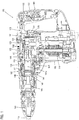
FIG. 1 is a sectional view showing an entire hammer drill according to a first embodiment. -
FIG. 2 is a plan view of the hammer drill showing an operating member of a mode switching mechanism. -
FIG. 3 is a plan view mainly showing the mode switching mechanism. -
FIG. 4 is a sectional view mainly showing the mode switching mechanism. -
FIG. 5 is a view as viewed from the direction of arrow A inFIG. 4 . -
FIG. 6 is a sectional view mainly showing the mode switching mechanism. -
FIG. 7 is a view as viewed from the direction of arrow B inFIG. 6 . - Representative examples of the present invention will now be described in detail with reference to the drawings. This detailed description is merely intended to teach a person skilled in the art further details for practicing preferred aspects of the present teachings and is not intended to limit the scope of the invention. Only the claims define the scope of the claimed invention. Therefore, combinations of features and steps disclosed within the following detailed description may not be necessary to practice the invention in the broadest sense, and are instead taught merely to particularly describe some representative examples of the invention, which detailed description will now be given with reference to the accompanying drawings.
- A first embodiment is now described with reference to
FIGS. 1 to 5 . In this embodiment, anelectric hammer drill 100 is described as a representative example of an impact tool. As shown inFIG. 1 , theelectric hammer drill 100 is designed as an impact tool to which ahammer bit 119 is coupled and performs drilling, chipping or other similar operation on a workpiece by causing thehammer bit 119 to linearly move in its axial direction and rotate around its axis. Thehammer bit 119 is a feature that corresponds to the "tool bit". - The
hammer drill 100 mainly includes the "tool body" in the form of abody 101 that forms an outer shell of thehammer drill 100. Thehammer bit 119 is detachably coupled to a front end region of thebody 101 via acylindrical tool holder 159. Thehammer bit 119 is inserted into a bit insertion hole of thetool holder 159 and held such that it is allowed to move in its axial direction with respect to the tool holder and prevented from rotating in its circumferential direction with respect to the tool holder. - A
handgrip 109 is designed to be held by a user and connected to an end of thebody 101 opposite from its front end region. Thehandgrip 109 is configured as a generally D-shaped main handle in side view which extends in a vertical direction (as viewed inFIG. 1 ) crossing the axial direction of thehammer bit 119 and has both ends in the extending direction connected to thebody 105. - In this embodiment, for the sake of convenience of explanation, the side of the
hammer bit 119 in a longitudinal direction of thebody 101 is defined as the "front" or "front region" and the side of thehandgrip 109 as the "rear" or "rear region". Further, an upper side of a paper plane inFIG. 1 is defined as the "upper" or "upper region" and its lower side as the "lower" or "lower region". - The
body 101 mainly includes amotor housing 103 that houses anelectric motor 110, agear housing 105 that houses amotion converting mechanism 120, astriking mechanism 140 and apower transmitting mechanism 150, and an outer housing that covers thegear housing 105. Theelectric motor 110 is disposed such that its rotation axis (output shaft) extends in a direction generally perpendicular to the longitudinal direction of the body 101 (the axial direction of the hammer bit 119), or in a vertical direction as viewed inFIG. 1 . Theelectric motor 110 is a feature that corresponds to the "motor". - The
motion converting mechanism 120 appropriately converts rotation of theelectric motor 110 into linear motion and then transmits it to thestriking mechanism 140, and thestriking mechanism 140 strikes thehammer bit 119 in the axial direction (leftward as viewed inFIG. 1 ). - The
motion converting mechanism 120 is provided to convert rotation of theelectric motor 110 into linear motion and transmit it to thestriking mechanism 140, and formed by a crank mechanism which is driven by theelectric motor 110 and has acrank shaft 121, acrank arm 123 and thepiston 125. Thepiston 125 forms a driving element for driving thestriking mechanism 140 and can slide in the same direction as the axial direction of the hammer bit within acylinder 141. - The
striking mechanism 140 mainly includes a striking element in the form of astriker 143 that is slidably disposed in thecylinder 141, an intermediate element in the form of animpact bolt 145 that is slidably disposed in thetool holder 159 and transmits kinetic energy of thestriker 143 to thehammer bit 119. Thecylinder 141 is coaxially disposed at the rear of thetool holder 159 and has anair chamber 141a partitioned by thepiston 125 and thestriker 143. Thestriker 143 is driven via an air spring action of theair chamber 141a by sliding movement of thepiston 125 and then collides with theimpact bolt 145 and strikes thehammer bit 119 via theimpact bolt 145. Theelectric motor 110, thestriker 143 and the crank mechanism which are described above form the "driving mechanism". - The
power transmitting mechanism 150 mainly includes a plurality of gears and appropriately reduces the speed of rotating power of theelectric motor 110 and then transmits it to thehammer bit 119 via a final shaft in the form of thetool holder 159. As a result, thehammer bit 119 is rotated in the circumferential direction. - In a power transmission path, the
power transmitting mechanism 150 has anengaging type clutch 151 that transmits the rotating output of theelectric motor 110 to thehammer bit 119 or interrupts the transmission. The clutch 151 is splined-fitted onto thetool holder 159 such that it can rotate together with thetool holder 159 and slide in the axial direction. One of the gears forming thepower transmitting mechanism 150 or agear 153 facing the clutch 151 has clutch teeth. When the clutch 151 is slid toward thegear 153, the clutch teeth of the clutch 151 engages with the clutch teeth of thegear 153 so that rotation of theelectric motor 110 is transmitted to thetool holder 159. When the clutch 151 is slid away from thegear 153, the clutch teeth are disengaged so that transmission of rotation is interrupted. Specifically, the clutch 151 can be switched between a power transmission state in which rotation of theelectric motor 110 is transmitted to thetool holder 159 and a power transmission interrupted state in which transmission of rotation is interrupted. Therefore, when the clutch 151 is switched to the power transmission state, thehammer bit 119 performs striking movement in its axial direction and rotation in its circumferential direction. Further, when the clutch 151 is switched to the power transmission interrupted state, thehammer bit 119 performs only striking movement. - An operating member for driving the
hammer bit 119 is now described which is operated to drive and stop theelectric motor 110. Arotary trigger 133 is provided in a grip of thehandgrip 109 and serves as a first operating member for turning on and off afirst switch 131. When thetrigger 133 is not operated, thetrigger 133 is spring-biased and held in an initial position (shown by two-dot chain line inFIG. 1 ) in which thefirst switch 131 is turned off. When the user depresses thetrigger 133, thetrigger 133 is rotated rearward (as shown by solid line inFIG. 1 ) and turns on thefirst switch 131. Further, arotary lever 137 is provided in a region of thebody 101 facing the grip of thehandgrip 109 and serves as a second operating member for turning on and off asecond switch 135. Thelever 137 in its non-operating state is spring-biased and held in an initial position in which thesecond switch 135 is turned off. When the user pushes thelever 137, thelever 137 is rotated forward and thesecond switch 135 is turned on. Further, once thesecond switch 135 is pushed by thelever 137 and turned on, thesecond switch 135 is held in the on state until it is pushed again. - When both the
first switch 131 and thesecond switch 135 which are constructed as described above are turned on, theelectric motor 110 is driven. Further, when at least either one of thefirst switch 131 and thesecond switch 135 is in the off state, theelectric motor 110 is stopped. - A drive
mode switching mechanism 160 for switching the drive mode of thehammer drill 100 is now described with reference toFIGS. 2 to 6 . As shown inFIG. 4 , the drivemode switching mechanism 160 mainly includes aswitching dial 161, aclutch control member 171 that controls the operating state of the clutch 151 by interlocking with user's operation of switching theswitching dial 161, aswitch control member 173 that controls the operating state of the switch by interlocking with user's operation of switching theswitching dial 161, and aleaf spring 175 that holds theswitching dial 161 in a selected position. The drivemode switching mechanism 160 and theswitching dial 161 are features that correspond to the "switching member" and the "operating member", respectively. - As shown in
FIG. 4 , thegear housing 105 forms ahousing space 105a that houses the crank mechanism, thestriking mechanism 140 and the power transmitting mechanisml50. Thishousing space 105a is a feature that corresponds to the "housing space".
Thegear housing 105 has a generally rectangular opening on the top which is located generally right above the crank mechanism, and this opening is closed by acover plate member 106 which is detachably mounted to thegear housing 105 by screws. Theswitching dial 161 is mounted on thecover plate member 106 such that it can rotate around arotation axis 161a extending in a vertical direction crossing an axis of thehammer bit 119. In thecover plate member 106, a circular steppedhole 106a having a small-diameter upper part and a large-diameter lower part is formed for mounting theswitching dial 161. The steppedhole 106a is a through hole extending in the vertical direction. The gear housing including thecover plate member 106 is a feature that corresponds to the "housing part". - The
switching dial 161 includes adial part 163 on which anoperating grip 163a is formed (seeFIG. 2 ), an upperflanged cylinder 165 disposed under thedial part 163 and a lowerflanged cylinder 167 disposed under the upperflanged cylinder 165, and each of these components is separately formed. A cylindrical part 165a of the upperflanged cylinder 165 is fitted into the small-diameter part of the steppedhole 106a of thecover plate member 106 from the upper side (outer side), while acylindrical part 167a of the lowerflanged cylinder 167 is fitted into the large-diameter part of the steppedhole 106a from the lower side (inner side). In this state, the upper and lowerflanged cylinders screw 166. Thus, the upperflanged cylinder 165 and the lowerflanged cylinder 167 are assembled to thecover plate member 106 such that they are prevented from coming off from thecover plate member 106 and can rotate around therotation axis 161a. - The
dial part 163 of theswitching dial 161 is connected to aflange 165b of the upperflanged cylinder 165 by ascrew 164 through an opening of anouter housing 107 which covers thegear housing 105, and thedial part 163 is disposed on the upper surface of thebody 101 or outside theouter housing 107 such that the user can turn it. - An O-
ring 113 is disposed between mating surfaces of the cylindrical part 165a of the upperflanged cylinder 165 and the small-diameter part of the steppedhole 106a. The O-ring 113 seals a clearance between the mating surfaces so as to prevent leakage of grease out of thegear housing 105. Furthermore, the O-ring 113 applies a moderate rotational resistance to the operation of turning theswitching dial 161. The grease is a feature that corresponds to the "lubricant". Further, an O-ring 115 is disposed between mating surfaces of thegear housing 105 and thecover plate member 106 and seals a clearance between the mating surfaces so as to prevent leakage of lubricant out of thegear housing 105. Further, other sealing members such as a packing and an oil seal may be used in place of the O-rings - In the
hammer drill 100 according to this embodiment, the drive mode can be switched among a first hammer mode, a second hammer mode, a hammer drill mode and a neutral mode by turning theswitching dial 161. In the first hammer mode, the user can perform a hammering operation (chipping operation) only by striking movement of thehammer bit 119 with thetrigger 133 locked in a depressed position. In the second hammer mode, the user can arbitrarily operate thetrigger 133 to perform a hammering operation only by striking movement of thehammer bit 119. In the hammer drill mode, the user can arbitrarily operate thetrigger 133 to perform a hammer drill operation (drilling operation) by striking movement and rotation of thehammer bit 119. In the neutral mode, the clutch 151 of thepower transmitting mechanism 150 is switched to a power transmission interrupted state, so that the user can hold the tip end of thehammer bit 119 with the fingers and adjust the orientation of thehammer bit 119 in the circumferential direction. - As shown in
FIG. 2 , amark 169a indicating the first hammer mode, amark 169b indicating the second hammer mode, amark 169c indicating the hammer drill mode and amark 169c indicating the neutral mode (each mark shown by a picture or pictogram) are put around thedial part 163 on an outer surface of thebody 101 or a top of theouter housing 107 and spaced at predetermined intervals in the circumferential direction. A desired mode is selected by turning theswitching dial 161 and pointing an arrow marked on theoperating grip 163a of thedial part 163 to one of themarks - As shown in
FIG. 4 , in theswitching dial 161, aneccentric shaft 165c having a circular section is provided in a position radially displaced a predetermined distance from arotation center 161a of theswitching dial 161 on theflange 165b of the upperflanged cylinder 165 and extends upward from the upper surface of theflange 165b. Theswitch control member 173 is connected to theeccentric shaft 165c. Theeccentric shaft 165c also serves as a connection part of connecting thedial part 163 to the upperflanged cylinder 165. A circulareccentric pin 167c is provided in a position radially displaced a predetermined distance from therotation center 161a of theswitching dial 161 and theclutch control member 171 is connected to theeccentric pin 167c. - As shown in
FIGS. 1 ,3 and4 , theswitch control member 173 is a long member extending in the longitudinal direction (the axial direction of the hammer bit 119) and allowed to move in the longitudinal direction. Theswitch control member 173 is loosely connected to theeccentric shaft 165c via an arcuate engagement hole 173a (seeFIG. 3 ) which is long in a horizontal direction (transverse direction) crossing the longitudinal direction. When theeccentric shaft 165c revolves, theswitch control member 173 is moved in the longitudinal direction by motion components of theeccentric shaft 165c in the axial direction of the hammer bit (in the front-back direction). Specifically, when theswitching dial 161 is switched to the first hammer mode, theswitch control member 173 is moved rearward to rotate thetrigger 133 rearward, and thereby turns on thefirst switch 131 and fixes the on state. When theswitching dial 161 is switched to the second hammer mode or hammer drill mode, theswitch control member 173 is moved forward to rotate thelever 137 forward, and thereby turns on thesecond switch 135. InFIG. 3 , each position (I), (II), (III), (IV) of theeccentric shaft 165c corresponding to each mode is shown by solid line or two-dot chain line. The positions (I), (II), (III) and (IV) inFIG. 3 correspond to the first hammer mode, the second hammer mode, the hammer drill mode and the neutral mode, respectively. - As shown in
FIGS. 1 ,3 ,4 and5 , theclutch control member 171 is a linkage member for mechanically linking theeccentric pin 167c of the lowerflanged cylinder 167 with the clutch 151 of thepower transmitting mechanism 150. Theclutch control member 171 is loosely connected to theeccentric pin 167c via aslot 171a (seeFIGS. 3 and5 ) which is long in a direction crossing the longitudinal direction. When theeccentric pin 167c revolves, theclutch control member 171 is moved in the longitudinal direction by motion components of theeccentric pin 167c in the axial direction of the hammer bit (in the front-back direction). Specifically, when theswitching dial 161 is switched to the first hammer mode, the second hammer mode or the neutral mode, theclutch control member 171 moves the clutch 151 forward and switches it to a power transmission interrupted state in which the clutch 151 is disengaged from the clutch teeth of thegear 153. When theswitching dial 161 is switched to the hammer drill mode, theclutch control member 171 moves the clutch 151 rearward and switches it to the power transmission state in which the clutch 151 is engaged with the clutch teeth of thegear 153. InFIG. 5 , each position (I), (II), (III), (IV) of theeccentric pin 167c corresponding to each mode is shown by solid line or two-dot chain line. The positions (I), (II), (III) and (IV) inFIG.5 correspond to the first hammer mode, the second hammer mode, the hammer drill mode and the neutral mode, respectively. - For example, when the arrow of the
operating grip 163a is pointed to themark 169d indicating the neutral mode, or the neutral mode is selected, by turning thedial part 163 of theswitching dial 161, theclutch control member 171 is moved forward, so that the clutch 151 of thepower transmitting mechanism 150 is switched to the power transmission interrupted state. Meanwhile, theswitch control member 173 is not operated to actuate thetrigger 133 and thelever 137. - Similarly, when the first hammer mode is selected by turning the
dial part 163, the clutch 151 of thepower transmitting mechanism 150 is switched to the power transmission interrupted state. Meanwhile, theswitch control member 173 pushes thetrigger 133 rearward and turns on thefirst switch 131. Specifically, thetrigger 133 is forcibly locked in the operated position in which thefirst switch 131 is turned on. In this state, when thesecond switch 135 is turned on by pushing thelever 137 forward with the user's finger, theelectric motor 110 is energized and driven. Even if the user's finger is released from thelever 137, as described above, thesecond switch 135 is held in the on state. Therefore, the user can continuously energize and drive theelectric motor 110 without keeping pressing thelever 137 with the finger to continuously perform a hammering operation by linear striking movement of thehammer bit 119. - Similarly, when the second hammer mode is selected by turning the
dial part 163, the clutch 151 of thepower transmitting mechanism 150 is switched to the power transmission interrupted state via theclutch control member 171. Meanwhile, theswitch control member 173 is moved forward, so that thetrigger 133 is released from the lock and allowed to be operated with the user's finger. Further, thelever 137 is pushed forward to turn on thesecond switch 135. Therefore, theelectric motor 110 is energized and driven when thetrigger 133 is depressed with the user's finger to turn on thefirst switch 131, while theelectric motor 110 is stopped when thetrigger 133 is released. Specifically, in the second hammer mode, theelectric motor 110 can be driven or stopped by user's arbitrary operation of thetrigger 133 to perform a hammering operation by thehammer bit 119. - Similarly, when the hammer drill mode is selected by turning the
dial part 163, the clutch 151 of thepower transmitting mechanism 150 is switched to the power transmission state via theclutch control member 171. Meanwhile, theswitch control member 173 is operated like in the second hammer mode. Specifically, thetrigger 133 is released from the lock, and thelever 137 is pushed forward to turn on thesecond switch 135. Therefore, in the hammer drill mode, the user can drive or stop theelectric motor 110 by arbitrarily operating thetrigger 133 with the finger to perform a hammer drill operation by striking movement and rotation of thehammer bit 119. - In this embodiment, when the
switching dial 161 is turned for mode switching, theswitching dial 161 is positioned and held in the selected mode position (angular position) by theleaf spring 175. As shown inFIGS. 4 and5 , theleaf spring 175 is a biasing member which is disposed between thecylindrical part 167a of the lowerflanged cylinder 167 and thecover plate member 106 and holds theswitching dial 161 in the selected position by elastically biasing thecylindrical part 167a of the lowerflanged cylinder 167 in the radial direction. Theleaf spring 175 is a feature that corresponds to the "biasing member". - In the
cover plate member 106, aninstallation space 177 for installing theleaf spring 175 is formed in a rear portion of the large-diameter part of the steppedhole 106a. Theinstallation space 177 is a recess which is open on a lower (inner) side of thecover plate member 106 and on a side facing the steppedhole 106a, and the open lower side is open to thehousing space 105a of thegear housing 105. Theinstallation space 177 in which theleaf spring 175 is disposed is a feature that corresponds to the "installation space". Aflange 167b of the lowerflanged cylinder 167 is disposed on the open lower side in the installation space 177 (seeFIG. 4 ). Theleaf spring 175 has a linearly extending rectangular shape and is disposed in theinstallation space 177 such that it extends in the horizontal direction crossing the axial direction of thehammer bit 119 and can elastically deform in the longitudinal direction. - As shown in
FIG. 5 , extending ends 175b of theleaf spring 175 are prevented from moving in the longitudinal direction by a wall surface of theinstallation space 177. A generallysemi-circular engagement protrusion 175a is formed in the center of theleaf spring 175 in the extending direction and protrudes forward toward thecylindrical part 167a of the lowerflanged cylinder 167. Theengagement protrusion 175a is elastically in contact with thecylindrical part 167a of the lowerflanged cylinder 167 in the radial direction. A first hammermode engagement recess 179a, a second hammermode engagement recess 179b, a hammer drillmode engagement recess 179c and a neutralmode engagement recess 179d are formed having a generally arcuate shape in the peripheral surface of thecylindrical part 167a of the lowerflanged cylinder 167, and theengagement protrusion 175a of theleaf spring 175 is selectively engaged with either one of these fourengagement recesses switching dial 161 is held in the selected mode position. - As shown in
FIG. 4 , in theleaf spring 175 disposed in theinstallation space 177, theengagement protrusion 175a is supported from below by theflange 167b of the lowerflanged cylinder 167. Specifically, theflange 167b serves as a supporting member for supporting theleaf spring 175. With such a construction, theleaf spring 175 can be prevented from falling out of theinstallation space 177 into an internal space of thegear housing 105. Theflange 167b of the lowerflanged cylinder 167 is a feature that corresponds to the "fall prevention member" and the "large-diameter portion" in the embodiment. - When the
switching dial 161 is turned, theleaf spring 175 constructed as described above elastically deforms in the longitudinal direction, so that theengagement protrusion 175a is engaged with or disengaged from either one of theengagement recesses cylindrical part 167a of the lowerflanged cylinder 167. By such provision of elastic engagement of theleaf spring 175, moderation feeling (click feeling) can be obtained in the operation of switching theswitching dial 161. - According to this embodiment, the
leaf spring 175 is disposed in theinstallation space 177 on the inner side of thecover plate member 106 which rotatably supports theswitching dial 161, or disposed inside thegear housing 105 that houses the crank mechanism, etc. With this construction, theleaf spring 175 can be protected from dust generated during operation. As a result, durability of theleaf spring 175 can be improved. - Lubricant is filled in the
gear housing 105 to lubricate the crank mechanism, etc. In this embodiment, with the construction in which the O-ring 113 is disposed between the upper flanged cylinder 156 and thecover plate member 106, the lubricant can be prevented from leaking to the outside of thegear housing 105. Particularly, in this embodiment, theleaf spring 175 is disposed inward relative to the O-ring 113 or inside thecover plate member 106. With this construction, due to the effect of preventing entry of dust by the O-ring 113, theleaf spring 175 can be further reliably protected from dust. At the same time, theleaf spring 175 is lubricated by the lubricant within thegear housing 105, so that its wear resistance is enhanced. - Further, in this embodiment, the
leaf spring 175 disposed in theinstallation space 177 of thecover plate member 106 is supported from below by theflange 167b of the lowerflanged cylinder 167 of theswitching dial 161. With this construction, theleaf spring 175 can be prevented from falling out of theinstallation space 177. - A second embodiment is now described with reference to
FIGS. 6 and7 . This embodiment is a modification to a holding means for holding theswitching dial 161 in a selected position. In the other points, this embodiment has the same construction as the above-described first embodiment. Therefore, components or elements which are substantially identical to those in the first embodiment are given like numerals and are not described or only briefly described. - In this embodiment, a
cylindrical roller 183 is disposed as an intervening member between aleaf spring 181 and the lowerflanged cylinder 167 of theswitching dial 161. Theleaf spring 181 and theroller 183 are features that correspond to the "biasing member" and the "intervening member", respectively. - As shown in
FIG. 7 , theleaf spring 181 has a generally arcuate shape protruding rearward, having a convexly forward curved central portion and ring-shaped ends in its longitudinal direction. Theleaf spring 181 is disposed in theinstallation space 177 of thecover plate member 106 such that it extends in the horizontal direction crossing the axial direction of thehammer bit 119, and can elastically deform in the longitudinal direction. Further, ring-like parts 181b on the ends of theleaf spring 181 are prevented from moving in the longitudinal direction by the wall surface forming theinstallation space 177. - The
roller 183 is shaped in a cylindrical form having an outer diameter corresponding to the size of the generallyarcuate engagement recesses cylindrical part 167a of the lowerflanged cylinder 167 and disposed between a central protrusion 181a of theleaf spring 181 and the peripheral surface of thecylindrical part 167a of the lowerflanged cylinder 167. Therefore, when theswitching dial 161 is turned, theroller 183 engages with either one of theengagement recesses cylindrical part 167a while receiving a biasing force of theleaf spring 181, so that theswitching dial 161 is held in the selected position. - In this embodiment, a
front wall 177a is formed in front of theinstallation space 177 and provided with aguide groove 177b which allows theroller 183 to move in the longitudinal direction. Further, theroller 183 is prevented from moving upward by thecover plate member 106 and supported in this state from below by theflange 167b of thecylinder 167. By provision of this construction, when theswitching dial 161 is turned, theroller 183 disposed between theleaf spring 181 and thecylindrical part 167a is moved in the longitudinal direction and engaged with or disengaged from theengagement recesses leaf spring 181. - In this embodiment, with the construction in which the
roller 183 is disposed between theleaf spring 181 and thecylindrical part 167a, the shape of theleaf spring 181 can be made simpler. Specifically, theleaf spring 181 can be formed to have a sectional shape having gentler irregularities to avoid stress concentration, so that durability of theleaf spring 181 can be improved. Further, the other effects of this embodiment, such as the effect of protecting theleaf spring 181 from dust, are identical to those of the above-described first embodiment. - In the embodiments, the hammer drill is described as a representative example of the impact tool, but the teachings may be applied to a hammer which causes the
hammer bit 119 to perform only striking movement in the axial direction. - The relationship between the features of the embodiments and the features of the teachings and matters used to specify the teachings are as follows. Naturally, each feature of the embodiments is only an example for embodiment relating to the corresponding matters to specify the teachings, and each feature of the teachings is not limited to this.
- The
gear housing 105 and thecover plate member 106 are features that correspond to the "housing part". - The
hammer bit 119 is a feature that corresponds to the "tool bit". - The crank mechanism, the
electric motor 110, and thestriker 143 are features that correspond to the "driving mechanism". - The drive
mode switching mechanism 160 is a feature that corresponds to the "switching member". - The
switching dial 161 is a feature that corresponds to the "operating member". - The leaf springs 175, 181 are features that correspond to the "biasing member".
- The
flange 167b of the lowerflanged cylinder 167 is a feature that corresponds to the "fall prevention member". - The
electric motor 110 is a feature that corresponds to the "motor". - The
striker 143 is a feature that corresponds to the "striking element". - The
roller 183 is a feature that corresponds to the "intervening member". - The
housing space 105a of thegear housing 105 and theinstallation space 177 of thecover plate member 106 are features that correspond to the "housing space". -
- 100 hammer drill (impact tool)
- 101 body
- 103 motor housing
- 105 gear housing (housing part)
- 105a housing space
- 106 cover plate member (housing part)
- 106a stepped hole (through hole)
- 107 outer housing
- 109 handgrip
- 110 electric motor (motor)
- 113 O-ring
- 115 O-ring
- 119 hammer bit (tool bit)
- 120 motion converting mechanism
- 121 crank shaft
- 123 crank arm
- 125 piston
- 131 first switch
- 133 trigger
- 135 second switch
- 137 lever
- 140 striking element
- 141 cylinder
- 141a air chamber
- 143 striker (striking element)
- 145 impact bolt
- 150 power transmitting mechanism
- 151 clutch
- 153 gear
- 159 tool holder
- 160 operation mode switching mechanism (switching member)
- 161 switching dial (operating member)
- 161a rotation axis
- 163 dial part
- 163a operating grip
- 164 screw
- 165 upper flanged cylinder
- 165a cylindrical part
- 165b flange
- 165c eccentric shaft
- 166 screw
- 167 lower flanged cylinder
- 167a cylindrical part
- 167b flange (large-diameter portion)
- 167c eccentric pin
- 169a - 169d mark
- 171 clutch control member
- 171a slot
- 173 switch control member
- 173a engagement hole
- 175 leaf spring (biasing member)
- 175a engagement protrusion
- 175b extending end
- 177 installation space
- 177a front wall
- 177b guide groove
- 179a - 179d engagement recess
- 181 leaf spring (biasing member)
- 181a central protrusion
- 181b ring-like part
- 183 roller (intervening member)
Claims (7)
- An impact tool which performs a hammering operation on a workpiece by at least linear movement of a tool bit (119) in an axial direction of the tool bit (119), comprising:a driving mechanism (110, 143) for driving the tool bit (119),a housing part (105, 106) that forms a housing space (105a) in which at least part of the driving mechanism (110, 143) is disposed, anda switching member (160) for switching a drive mode of the impact tool, wherein:the switching member (160) has an operating member (161) that is operated by a user for mode switching, and a biasing member (175; 181) that is disposed between the operating member (161) and the housing part (105, 106) and biases the operating member (161) so as to hold the operating member (161) in a selected position,the biasing member (175; 181) is disposed in the housing space, andthe housing part (105, 106) is provided with a through hole (106a) through which the operating member (161) is inserted, the operating member (161) has a large-diameter portion (167b) having a larger diameter than the through hole (106a), and the large-diameter portion (167b) is disposed in the housing space (105a) and supports the biasing member (175; 181), characterized in thatthe biasing member (175; 181) is a leaf spring, andthe leaf spring (175; 181) is installed in an installation space (177) formed as a recess in a rear portion of the through hole (106a), which recess is open to the housing space (105a) on the inner side of the housing part (106) and open on a side facing the through hole (106a).
- The impact tool as defined in claim 1, wherein a lubricant for lubricating the driving mechanism (110, 143) is provided in the housing space (105a), and a sealing member (115) is provided between the housing part (105, 106) and the operating member (161).
- The impact tool as defined in claim 1 or 2, wherein the biasing member (175) is held on a region of the housing part (105, 106).
- The impact tool as defined in claim 1, 2 or 3, wherein the switching member (160) is provided with a falling prevention member (167b) for preventing the biasing member (175) from falling out of the housing part (105, 106).
- The impact tool as defined in any one of claims 1 to 4, wherein the driving mechanism (110, 143) has a motor (110), a striking element (143) that strikes the tool bit (119) by linear movement in the axial direction of the tool bit (119), and a crank mechanism that converts rotation of the motor (110) into linear motion and then drives the striking element (143), and wherein the crank mechanism is disposed in the housing space (105a).
- The impact tool as defined in any one of claims 1 to 5, wherein an intervening member (183) is disposed between the operating member (161) and the biasing member (175).
- The impact tool as defined in claim 6, wherein an O-ring (113) is disposed between the operating member (161) and the through hole (106a).
Applications Claiming Priority (1)
| Application Number | Priority Date | Filing Date | Title |
|---|---|---|---|
| JP2012253722A JP2014100762A (en) | 2012-11-19 | 2012-11-19 | Impact tool |
Publications (2)
| Publication Number | Publication Date |
|---|---|
| EP2732925A1 EP2732925A1 (en) | 2014-05-21 |
| EP2732925B1 true EP2732925B1 (en) | 2018-01-03 |
Family
ID=49679321
Family Applications (1)
| Application Number | Title | Priority Date | Filing Date |
|---|---|---|---|
| EP13193209.7A Active EP2732925B1 (en) | 2012-11-19 | 2013-11-15 | Impact tool |
Country Status (5)
| Country | Link |
|---|---|
| US (1) | US9463563B2 (en) |
| EP (1) | EP2732925B1 (en) |
| JP (1) | JP2014100762A (en) |
| CN (1) | CN103817657A (en) |
| RU (1) | RU2013150502A (en) |
Cited By (1)
| Publication number | Priority date | Publication date | Assignee | Title |
|---|---|---|---|---|
| EP3839996B1 (en) * | 2019-12-19 | 2024-01-31 | Globe (Jiangsu) Co., Ltd. | Electric ground drill |
Families Citing this family (9)
| Publication number | Priority date | Publication date | Assignee | Title |
|---|---|---|---|---|
| WO2016196918A1 (en) | 2015-06-05 | 2016-12-08 | Ingersoll-Rand Company | Power tool user interfaces |
| WO2016196891A1 (en) * | 2015-06-05 | 2016-12-08 | Ingersoll-Rand Company | Power tool user interfaces |
| US11260517B2 (en) | 2015-06-05 | 2022-03-01 | Ingersoll-Rand Industrial U.S., Inc. | Power tool housings |
| WO2016196979A1 (en) | 2015-06-05 | 2016-12-08 | Ingersoll-Rand Company | Impact tools with ring gear alignment features |
| WO2016196984A1 (en) | 2015-06-05 | 2016-12-08 | Ingersoll-Rand Company | Power tools with user-selectable operational modes |
| JP6912224B2 (en) | 2017-03-03 | 2021-08-04 | 株式会社マキタ | Work tools |
| US11261964B2 (en) | 2018-05-17 | 2022-03-01 | Black & Decker Inc. | Compliant shifting mechanism and multi-speed power tool having same |
| DE102018214092A1 (en) * | 2018-08-21 | 2020-02-27 | Robert Bosch Gmbh | Switching device for a hammer drill and hammer drill with a switching device |
| JP2022188996A (en) * | 2021-06-10 | 2022-12-22 | 株式会社マキタ | Rotary striking tool |
Family Cites Families (23)
| Publication number | Priority date | Publication date | Assignee | Title |
|---|---|---|---|---|
| US3837409A (en) * | 1973-02-26 | 1974-09-24 | Skil Corp | Rotary hammer power tool |
| DE2516406C3 (en) * | 1975-04-15 | 1981-11-19 | Robert Bosch Gmbh, 7000 Stuttgart | Hammer drill |
| JPS6053482U (en) * | 1983-09-16 | 1985-04-15 | 日立工機株式会社 | Change lever mounting structure |
| DE4135240A1 (en) * | 1991-10-25 | 1993-04-29 | Bosch Gmbh Robert | DRILLING HAMMER |
| JP2602411Y2 (en) * | 1993-11-26 | 2000-01-17 | 日立工機株式会社 | Switching mechanism of impact tool |
| DE4441793B4 (en) * | 1994-11-24 | 2006-08-24 | Robert Bosch Gmbh | Switching device for a hand tool |
| JP3424880B2 (en) * | 1995-08-18 | 2003-07-07 | 株式会社マキタ | Hammer drill |
| DE19717712A1 (en) * | 1997-04-18 | 1998-10-22 | Black & Decker Inc | Hammer drill |
| DE10031050A1 (en) * | 2000-06-26 | 2002-01-10 | Hilti Ag | Hand tool |
| DE10108124A1 (en) | 2001-02-21 | 2002-08-29 | Hilti Ag | Mode selection rotary switch for a hand tool device |
| DE10111748A1 (en) * | 2001-03-12 | 2002-09-19 | Hilti Ag | Switchgear for a combined hand tool |
| JP4509662B2 (en) * | 2004-06-16 | 2010-07-21 | 株式会社マキタ | Electric impact tool |
| DE102004057686A1 (en) * | 2004-11-30 | 2006-06-01 | Robert Bosch Gmbh | switching device |
| DE102005041448A1 (en) * | 2005-08-31 | 2007-03-01 | Robert Bosch Gmbh | Hammer drill, comprises manually operated switch with outer shell and sealing ring |
| US7469752B2 (en) * | 2005-12-02 | 2008-12-30 | Makita Corporation | Power tool |
| JP4812471B2 (en) * | 2006-03-09 | 2011-11-09 | 株式会社マキタ | Work tools |
| DE102006059078A1 (en) * | 2006-12-14 | 2008-06-19 | Robert Bosch Gmbh | Electric device with snap-on rotatable control element |
| JP2008183633A (en) * | 2007-01-26 | 2008-08-14 | Makita Corp | Hammer drill |
| DE102007009986A1 (en) * | 2007-03-02 | 2008-09-04 | Robert Bosch Gmbh | Hand tool, especially a hammer drill or chisel hammer, comprises a switch spring with a receiving region for holding a transmission element of a mounted actuating unit during assembly of a gear housing and a gear unit |
| CN101407053B (en) * | 2007-10-09 | 2011-06-29 | 苏州宝时得电动工具有限公司 | Power tool |
| JP5357897B2 (en) * | 2008-12-19 | 2013-12-04 | 株式会社マキタ | Work tools |
| DE102009005248A1 (en) * | 2009-01-13 | 2010-07-15 | C. & E. Fein Gmbh | Power tool with switchable gearbox |
| JP5837750B2 (en) * | 2011-02-01 | 2015-12-24 | 株式会社マキタ | Work tools |
-
2012
- 2012-11-19 JP JP2012253722A patent/JP2014100762A/en active Pending
-
2013
- 2013-10-24 CN CN201310507543.8A patent/CN103817657A/en active Pending
- 2013-11-06 US US14/073,499 patent/US9463563B2/en active Active
- 2013-11-12 RU RU2013150502/02A patent/RU2013150502A/en not_active Application Discontinuation
- 2013-11-15 EP EP13193209.7A patent/EP2732925B1/en active Active
Non-Patent Citations (1)
| Title |
|---|
| None * |
Cited By (1)
| Publication number | Priority date | Publication date | Assignee | Title |
|---|---|---|---|---|
| EP3839996B1 (en) * | 2019-12-19 | 2024-01-31 | Globe (Jiangsu) Co., Ltd. | Electric ground drill |
Also Published As
| Publication number | Publication date |
|---|---|
| JP2014100762A (en) | 2014-06-05 |
| US9463563B2 (en) | 2016-10-11 |
| RU2013150502A (en) | 2015-05-20 |
| CN103817657A (en) | 2014-05-28 |
| US20140138111A1 (en) | 2014-05-22 |
| EP2732925A1 (en) | 2014-05-21 |
Similar Documents
| Publication | Publication Date | Title |
|---|---|---|
| EP2732925B1 (en) | Impact tool | |
| US7647985B2 (en) | Hammer drill | |
| US7469752B2 (en) | Power tool | |
| EP2481526B1 (en) | Power tool | |
| EP2103389B1 (en) | Impact tool | |
| US9321163B2 (en) | Impact tool | |
| RU2577639C2 (en) | Drive tool | |
| EP1422028B1 (en) | Hammer drill with a mechanism for preventing inadvertent hammer blows | |
| EP2390049B1 (en) | Impact Tool | |
| JP5116029B2 (en) | Hammer drill | |
| US7383893B2 (en) | Electric hammer drill | |
| US7549484B2 (en) | Power tool | |
| CA2021785A1 (en) | Powered impact wrench | |
| JP2006142459A (en) | Hammer drill | |
| CN109693211B (en) | Impact tool | |
| JP2007152481A (en) | Working tool | |
| CN106041833B (en) | Impact tool | |
| JP4568600B2 (en) | Hammer drill | |
| EP2085190B1 (en) | Percussion tool | |
| GB2160810A (en) | Hammer drill | |
| JP4485462B2 (en) | Work tools | |
| RU2417875C2 (en) | Mechanised tool |
Legal Events
| Date | Code | Title | Description |
|---|---|---|---|
| PUAI | Public reference made under article 153(3) epc to a published international application that has entered the european phase |
Free format text: ORIGINAL CODE: 0009012 |
|
| 17P | Request for examination filed |
Effective date: 20131115 |
|
| AK | Designated contracting states |
Kind code of ref document: A1 Designated state(s): AL AT BE BG CH CY CZ DE DK EE ES FI FR GB GR HR HU IE IS IT LI LT LU LV MC MK MT NL NO PL PT RO RS SE SI SK SM TR |
|
| AX | Request for extension of the european patent |
Extension state: BA ME |
|
| R17P | Request for examination filed (corrected) |
Effective date: 20141120 |
|
| RBV | Designated contracting states (corrected) |
Designated state(s): AL AT BE BG CH CY CZ DE DK EE ES FI FR GB GR HR HU IE IS IT LI LT LU LV MC MK MT NL NO PL PT RO RS SE SI SK SM TR |
|
| 17Q | First examination report despatched |
Effective date: 20161108 |
|
| GRAP | Despatch of communication of intention to grant a patent |
Free format text: ORIGINAL CODE: EPIDOSNIGR1 |
|
| RIC1 | Information provided on ipc code assigned before grant |
Ipc: B25D 17/26 20060101ALI20170523BHEP Ipc: H01H 9/06 20060101ALI20170523BHEP Ipc: H01H 9/20 20060101ALI20170523BHEP Ipc: G05G 5/06 20060101ALI20170523BHEP Ipc: G05G 5/08 20060101ALI20170523BHEP Ipc: B25D 16/00 20060101AFI20170523BHEP Ipc: B25F 5/00 20060101ALI20170523BHEP |
|
| INTG | Intention to grant announced |
Effective date: 20170612 |
|
| GRAS | Grant fee paid |
Free format text: ORIGINAL CODE: EPIDOSNIGR3 |
|
| GRAA | (expected) grant |
Free format text: ORIGINAL CODE: 0009210 |
|
| AK | Designated contracting states |
Kind code of ref document: B1 Designated state(s): AL AT BE BG CH CY CZ DE DK EE ES FI FR GB GR HR HU IE IS IT LI LT LU LV MC MK MT NL NO PL PT RO RS SE SI SK SM TR |
|
| REG | Reference to a national code |
Ref country code: GB Ref legal event code: FG4D |
|
| REG | Reference to a national code |
Ref country code: CH Ref legal event code: EP Ref country code: AT Ref legal event code: REF Ref document number: 959775 Country of ref document: AT Kind code of ref document: T Effective date: 20180115 |
|
| REG | Reference to a national code |
Ref country code: IE Ref legal event code: FG4D |
|
| REG | Reference to a national code |
Ref country code: DE Ref legal event code: R096 Ref document number: 602013031579 Country of ref document: DE |
|
| REG | Reference to a national code |
Ref country code: NL Ref legal event code: MP Effective date: 20180103 |
|
| REG | Reference to a national code |
Ref country code: LT Ref legal event code: MG4D |
|
| REG | Reference to a national code |
Ref country code: AT Ref legal event code: MK05 Ref document number: 959775 Country of ref document: AT Kind code of ref document: T Effective date: 20180103 |
|
| PG25 | Lapsed in a contracting state [announced via postgrant information from national office to epo] |
Ref country code: NL Free format text: LAPSE BECAUSE OF FAILURE TO SUBMIT A TRANSLATION OF THE DESCRIPTION OR TO PAY THE FEE WITHIN THE PRESCRIBED TIME-LIMIT Effective date: 20180103 |
|
| PG25 | Lapsed in a contracting state [announced via postgrant information from national office to epo] |
Ref country code: NO Free format text: LAPSE BECAUSE OF FAILURE TO SUBMIT A TRANSLATION OF THE DESCRIPTION OR TO PAY THE FEE WITHIN THE PRESCRIBED TIME-LIMIT Effective date: 20180403 Ref country code: HR Free format text: LAPSE BECAUSE OF FAILURE TO SUBMIT A TRANSLATION OF THE DESCRIPTION OR TO PAY THE FEE WITHIN THE PRESCRIBED TIME-LIMIT Effective date: 20180103 Ref country code: CY Free format text: LAPSE BECAUSE OF FAILURE TO SUBMIT A TRANSLATION OF THE DESCRIPTION OR TO PAY THE FEE WITHIN THE PRESCRIBED TIME-LIMIT Effective date: 20180103 Ref country code: FI Free format text: LAPSE BECAUSE OF FAILURE TO SUBMIT A TRANSLATION OF THE DESCRIPTION OR TO PAY THE FEE WITHIN THE PRESCRIBED TIME-LIMIT Effective date: 20180103 Ref country code: ES Free format text: LAPSE BECAUSE OF FAILURE TO SUBMIT A TRANSLATION OF THE DESCRIPTION OR TO PAY THE FEE WITHIN THE PRESCRIBED TIME-LIMIT Effective date: 20180103 Ref country code: LT Free format text: LAPSE BECAUSE OF FAILURE TO SUBMIT A TRANSLATION OF THE DESCRIPTION OR TO PAY THE FEE WITHIN THE PRESCRIBED TIME-LIMIT Effective date: 20180103 |
|
| PG25 | Lapsed in a contracting state [announced via postgrant information from national office to epo] |
Ref country code: RS Free format text: LAPSE BECAUSE OF FAILURE TO SUBMIT A TRANSLATION OF THE DESCRIPTION OR TO PAY THE FEE WITHIN THE PRESCRIBED TIME-LIMIT Effective date: 20180103 Ref country code: AT Free format text: LAPSE BECAUSE OF FAILURE TO SUBMIT A TRANSLATION OF THE DESCRIPTION OR TO PAY THE FEE WITHIN THE PRESCRIBED TIME-LIMIT Effective date: 20180103 Ref country code: PL Free format text: LAPSE BECAUSE OF FAILURE TO SUBMIT A TRANSLATION OF THE DESCRIPTION OR TO PAY THE FEE WITHIN THE PRESCRIBED TIME-LIMIT Effective date: 20180103 Ref country code: LV Free format text: LAPSE BECAUSE OF FAILURE TO SUBMIT A TRANSLATION OF THE DESCRIPTION OR TO PAY THE FEE WITHIN THE PRESCRIBED TIME-LIMIT Effective date: 20180103 Ref country code: SE Free format text: LAPSE BECAUSE OF FAILURE TO SUBMIT A TRANSLATION OF THE DESCRIPTION OR TO PAY THE FEE WITHIN THE PRESCRIBED TIME-LIMIT Effective date: 20180103 Ref country code: BG Free format text: LAPSE BECAUSE OF FAILURE TO SUBMIT A TRANSLATION OF THE DESCRIPTION OR TO PAY THE FEE WITHIN THE PRESCRIBED TIME-LIMIT Effective date: 20180403 Ref country code: IS Free format text: LAPSE BECAUSE OF FAILURE TO SUBMIT A TRANSLATION OF THE DESCRIPTION OR TO PAY THE FEE WITHIN THE PRESCRIBED TIME-LIMIT Effective date: 20180503 Ref country code: GR Free format text: LAPSE BECAUSE OF FAILURE TO SUBMIT A TRANSLATION OF THE DESCRIPTION OR TO PAY THE FEE WITHIN THE PRESCRIBED TIME-LIMIT Effective date: 20180404 |
|
| REG | Reference to a national code |
Ref country code: DE Ref legal event code: R097 Ref document number: 602013031579 Country of ref document: DE |
|
| PG25 | Lapsed in a contracting state [announced via postgrant information from national office to epo] |
Ref country code: AL Free format text: LAPSE BECAUSE OF FAILURE TO SUBMIT A TRANSLATION OF THE DESCRIPTION OR TO PAY THE FEE WITHIN THE PRESCRIBED TIME-LIMIT Effective date: 20180103 Ref country code: EE Free format text: LAPSE BECAUSE OF FAILURE TO SUBMIT A TRANSLATION OF THE DESCRIPTION OR TO PAY THE FEE WITHIN THE PRESCRIBED TIME-LIMIT Effective date: 20180103 Ref country code: RO Free format text: LAPSE BECAUSE OF FAILURE TO SUBMIT A TRANSLATION OF THE DESCRIPTION OR TO PAY THE FEE WITHIN THE PRESCRIBED TIME-LIMIT Effective date: 20180103 Ref country code: IT Free format text: LAPSE BECAUSE OF FAILURE TO SUBMIT A TRANSLATION OF THE DESCRIPTION OR TO PAY THE FEE WITHIN THE PRESCRIBED TIME-LIMIT Effective date: 20180103 |
|
| PLBE | No opposition filed within time limit |
Free format text: ORIGINAL CODE: 0009261 |
|
| STAA | Information on the status of an ep patent application or granted ep patent |
Free format text: STATUS: NO OPPOSITION FILED WITHIN TIME LIMIT |
|
| PG25 | Lapsed in a contracting state [announced via postgrant information from national office to epo] |
Ref country code: SK Free format text: LAPSE BECAUSE OF FAILURE TO SUBMIT A TRANSLATION OF THE DESCRIPTION OR TO PAY THE FEE WITHIN THE PRESCRIBED TIME-LIMIT Effective date: 20180103 Ref country code: DK Free format text: LAPSE BECAUSE OF FAILURE TO SUBMIT A TRANSLATION OF THE DESCRIPTION OR TO PAY THE FEE WITHIN THE PRESCRIBED TIME-LIMIT Effective date: 20180103 Ref country code: SM Free format text: LAPSE BECAUSE OF FAILURE TO SUBMIT A TRANSLATION OF THE DESCRIPTION OR TO PAY THE FEE WITHIN THE PRESCRIBED TIME-LIMIT Effective date: 20180103 Ref country code: CZ Free format text: LAPSE BECAUSE OF FAILURE TO SUBMIT A TRANSLATION OF THE DESCRIPTION OR TO PAY THE FEE WITHIN THE PRESCRIBED TIME-LIMIT Effective date: 20180103 |
|
| 26N | No opposition filed |
Effective date: 20181005 |
|
| PG25 | Lapsed in a contracting state [announced via postgrant information from national office to epo] |
Ref country code: SI Free format text: LAPSE BECAUSE OF FAILURE TO SUBMIT A TRANSLATION OF THE DESCRIPTION OR TO PAY THE FEE WITHIN THE PRESCRIBED TIME-LIMIT Effective date: 20180103 |
|
| REG | Reference to a national code |
Ref country code: CH Ref legal event code: PL |
|
| GBPC | Gb: european patent ceased through non-payment of renewal fee |
Effective date: 20181115 |
|
| PG25 | Lapsed in a contracting state [announced via postgrant information from national office to epo] |
Ref country code: LU Free format text: LAPSE BECAUSE OF NON-PAYMENT OF DUE FEES Effective date: 20181115 Ref country code: MC Free format text: LAPSE BECAUSE OF FAILURE TO SUBMIT A TRANSLATION OF THE DESCRIPTION OR TO PAY THE FEE WITHIN THE PRESCRIBED TIME-LIMIT Effective date: 20180103 |
|
| REG | Reference to a national code |
Ref country code: BE Ref legal event code: MM Effective date: 20181130 |
|
| REG | Reference to a national code |
Ref country code: IE Ref legal event code: MM4A |
|
| PG25 | Lapsed in a contracting state [announced via postgrant information from national office to epo] |
Ref country code: CH Free format text: LAPSE BECAUSE OF NON-PAYMENT OF DUE FEES Effective date: 20181130 Ref country code: LI Free format text: LAPSE BECAUSE OF NON-PAYMENT OF DUE FEES Effective date: 20181130 |
|
| PG25 | Lapsed in a contracting state [announced via postgrant information from national office to epo] |
Ref country code: FR Free format text: LAPSE BECAUSE OF NON-PAYMENT OF DUE FEES Effective date: 20181130 Ref country code: IE Free format text: LAPSE BECAUSE OF NON-PAYMENT OF DUE FEES Effective date: 20181115 |
|
| PG25 | Lapsed in a contracting state [announced via postgrant information from national office to epo] |
Ref country code: BE Free format text: LAPSE BECAUSE OF NON-PAYMENT OF DUE FEES Effective date: 20181130 |
|
| PG25 | Lapsed in a contracting state [announced via postgrant information from national office to epo] |
Ref country code: GB Free format text: LAPSE BECAUSE OF NON-PAYMENT OF DUE FEES Effective date: 20181115 |
|
| PG25 | Lapsed in a contracting state [announced via postgrant information from national office to epo] |
Ref country code: MT Free format text: LAPSE BECAUSE OF NON-PAYMENT OF DUE FEES Effective date: 20181115 |
|
| PG25 | Lapsed in a contracting state [announced via postgrant information from national office to epo] |
Ref country code: TR Free format text: LAPSE BECAUSE OF FAILURE TO SUBMIT A TRANSLATION OF THE DESCRIPTION OR TO PAY THE FEE WITHIN THE PRESCRIBED TIME-LIMIT Effective date: 20180103 |
|
| PG25 | Lapsed in a contracting state [announced via postgrant information from national office to epo] |
Ref country code: PT Free format text: LAPSE BECAUSE OF FAILURE TO SUBMIT A TRANSLATION OF THE DESCRIPTION OR TO PAY THE FEE WITHIN THE PRESCRIBED TIME-LIMIT Effective date: 20180103 |
|
| PG25 | Lapsed in a contracting state [announced via postgrant information from national office to epo] |
Ref country code: HU Free format text: LAPSE BECAUSE OF FAILURE TO SUBMIT A TRANSLATION OF THE DESCRIPTION OR TO PAY THE FEE WITHIN THE PRESCRIBED TIME-LIMIT; INVALID AB INITIO Effective date: 20131115 Ref country code: MK Free format text: LAPSE BECAUSE OF NON-PAYMENT OF DUE FEES Effective date: 20180103 |
|
| PGFP | Annual fee paid to national office [announced via postgrant information from national office to epo] |
Ref country code: DE Payment date: 20230929 Year of fee payment: 11 |