EP2085190B1 - Percussion tool - Google Patents
Percussion tool Download PDFInfo
- Publication number
- EP2085190B1 EP2085190B1 EP07832324A EP07832324A EP2085190B1 EP 2085190 B1 EP2085190 B1 EP 2085190B1 EP 07832324 A EP07832324 A EP 07832324A EP 07832324 A EP07832324 A EP 07832324A EP 2085190 B1 EP2085190 B1 EP 2085190B1
- Authority
- EP
- European Patent Office
- Prior art keywords
- bit
- holding
- tool
- region
- holding region
- Prior art date
- Legal status (The legal status is an assumption and is not a legal conclusion. Google has not performed a legal analysis and makes no representation as to the accuracy of the status listed.)
- Not-in-force
Links
Images

Classifications
-
- B—PERFORMING OPERATIONS; TRANSPORTING
- B25—HAND TOOLS; PORTABLE POWER-DRIVEN TOOLS; MANIPULATORS
- B25D—PERCUSSIVE TOOLS
- B25D17/00—Details of, or accessories for, portable power-driven percussive tools
- B25D17/08—Means for retaining and guiding the tool bit, e.g. chucks allowing axial oscillation of the tool bit
- B25D17/084—Rotating chucks or sockets
- B25D17/088—Rotating chucks or sockets with radial movable locking elements co-operating with bit shafts specially adapted therefor
-
- B—PERFORMING OPERATIONS; TRANSPORTING
- B25—HAND TOOLS; PORTABLE POWER-DRIVEN TOOLS; MANIPULATORS
- B25D—PERCUSSIVE TOOLS
- B25D2217/00—Details of, or accessories for, portable power-driven percussive tools
- B25D2217/003—Details relating to chucks with radially movable locking elements
- B25D2217/0038—Locking members of special shape
- B25D2217/0042—Ball-shaped locking members
-
- B—PERFORMING OPERATIONS; TRANSPORTING
- B25—HAND TOOLS; PORTABLE POWER-DRIVEN TOOLS; MANIPULATORS
- B25D—PERCUSSIVE TOOLS
- B25D2222/00—Materials of the tool or the workpiece
- B25D2222/21—Metals
- B25D2222/42—Steel
Definitions
- the present invention relates to an impact tool in accordance with the preamble of claim 1 that performs a predetermined operation on a workpiece by a striking movement of a tool bit in its axial direction.
- WO02/20224 discloses an impact tool having a tool holder designed to resist wear.
- a sleeve made of a material harder than a body of the tool holder is provided as a separate member and press-fitted into the body in order to reduce wear of the inner wall surface of the bit holding hole.
- an impact tool is configured such that steel balls arranged on the tool holder prevent removal of a hammer bit inserted into a bit holding hole of a tool holder. Therefore, an axial impact force is applied from the hammer bit to the tool holder via the steel balls during striking movement of the hammer bit. Accordingly, in the above-described known technique in which a hard sleeve is formed along the entire length of the bit holding hole into which a shank of the hammer bit is inserted, the sleeve is acted upon by an impact force.
- the sleeve made of a hard material however may crack on impact due to its high hardness.
- slots in which the steel balls are disposed are formed through the sleeve in the radial direction. It is however difficult to form the slots by machining because the sleeve is hard. Therefore, in the known impact tool, further improvements are required in durability and machinability.
- an object of the invention to provide an effective technique for improving the durability and machinability of a tool holder for holding a tool bit in an impact tool.
- the present invention provides an impact tool having the features of claim 1 which includes a tool holder having a bit holding hole. A tool bit is inserted into the bit holding hole and the tool bit is held so as to be movable in an axial direction to perform a predetermined operation on a workpiece at least by striking movement of the tool bit in an axial direction.
- the manner "at least by striking movement of the tool bit in an axial direction” here includes the manner of driving the tool bit only by striking movement, and the manner of driving the tool bit by combination of striking movement and rotation.
- the impact tool according to this invention has a bit holding region which is held in contact with an outer surface of the tool bit inserted into the bit holding hole and which holds the tool bit such that the tool bit can move in the axial direction.
- the bit holding region has a first holding region, a second holding region and a third holding region, arranged in this order in the bit holding hole from the side of a bit insertion opening toward the far side from the opening.
- the first holding region is provided as a region for holding the tool bit inserted into the bit holding hole, while allowing the tool bit to move in the axial direction with respect to the bit holding hole.
- the second holding region is provided as a region to dispose a removal preventing member which engages with the tool bit and thereby prevents the tool bit from becoming slipped out of the bit holding hole.
- the third holding region is provided as a region for holding an inserted end of the tool bit inserted into the bit holding hole, while allowing it to move in the axial direction with respect to the bit holding hole.
- the hardness of the first holding region is higher than that of the second holding region.
- the "hardness of the first holding region” is preferably set to a hardness of 60 Rockwell Hardness C-Scale (HRC) or higher, and the first holding region is suitably formed of alloy tool steels (SKD), high speed tool steels (SKH) or high-carbon chrome bearing steels (SUJ).
- the first holding region on the bit insertion opening side where wear most easily occurs has a higher hardness than the second holding region, so that wear resistance of the first holding region can be increased.
- wear of the first holding region can be reduced and its durability can be increased.
- Wear of the bit holding region causes runout of the tool bit. Then, for example, in the case of a hammer drill, in which the rotating force of the tool holder is transmitted to the tool bit, torque transmitting projections formed on the tool holder may suffer wear.
- a removal preventing member for example, steel balls
- the regions other than the first holding region preferably have as high a hardness as in a conventional technique.
- the second holding region in which the removal preventing member is disposed can preferably have as high a hardness as in a conventional technique. Therefore, cracks which might be produced due to too high hardness can be prevented from being produced on impact during striking movement of the hammer bit. Moreover, the machinability in forming a radial through hole for receiving the removal preventing member in the second holding region, for example, by machining, is not impaired because the hardness of the second holding region can preferably be as high as in a conventional technique.
- the hardness of the third holding region is higher than that of the second holding region.
- the "hardness of the third holding region" is equal to that of the first holding region.
- the first holding region of the first and third holding regions is formed of a material having a higher hardness than the second holding region and as a separate member.
- the "separate member" in this invention typically represents a ring-like member.
- the manner of being “formed” here typically represents the manner in which the ring-like member is press-fitted into the bore of the tool holder, but it also suitably includes manners other than press-fitting, such as fixing by screws or by welding.
- the bit holding hole having the bit holding region of different hardnesses in the axial direction can be easily produced by forming the first holding region as a separate member, so that ease of production can be enhanced.
- the removal preventing member in the second holding region prevents removal of the tool bit by moving in a radially inward direction of the bit holding hole and engaging with the tool bit, and allows removal of the tool bit by moving in a radially outward direction of the bit holding hole.
- an opening is formed in the second holding region and the removal preventing member is disposed in the opening so as to be movable in the radial direction.
- the opening in which the removal preventing member is disposed is formed in the second holding region having a lower hardness than the first holding region. Therefore, the opening can be easily formed, for example, by machining, and thus the machinability can be increased.
- an effective technique for improving the durability and machinability of a tool holder for holding a tool bit in an impact tool is provided.
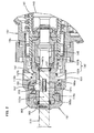
- FIG. 1 is a sectional side view showing an entire electric hammer drill 101 according to this embodiment.
- the hammer drill 101 mainly includes a body 103 that forms an outer shell of the hammer drill 101, a hammer bit 119 detachably coupled to the tip end region (on the left side as viewed in FIG. 1 ) of the body 103 via a tool holder 137, and a grip 109 connected to the body 103 on the side opposite to the hammer bit 119 and designed to be held by a user.
- the hammer bit 119 is mounted such that it is allowed to reciprocate with respect to the tool holder 137 in its axial direction and prevented from rotating with respect to the tool holder in its circumferential direction.
- the hammer bit 119 is a feature that corresponds to the "tool bit" according to the present invention.
- the side of the hammer bit 119 is taken as the front side and the side of the grip 109 as the rear side.
- the body 103 mainly includes a motor housing 105 that houses a driving motor 111, and a gear housing 107 that houses a motion converting mechanism 113, a power transmitting mechanism 114 and a striking mechanism 115.
- the motor housing 105 and the gear housing 107 are connected together, for example, by screws (not shown)
- the rotating output of the driving motor 111 is appropriately converted into linear motion via the motion converting mechanism 113 and transmitted to the striking mechanism 115. Then, an impact force is generated in the axial direction of the hammer bit 119 via the striking mechanism 115. Further, the power transmitting mechanism 114 appropriately reduces the speed of the rotating output of the driving motor 111 and then transmits the rotating output as a rotating force to the hammer bit 119. As a result, the hammer bit 119 is caused to rotate in the circumferential direction.
- the driving motor 111 is driven when a trigger 117 on the grip 109 is depressed.
- the motion converting mechanism 113 mainly includes a driving gear 121 that is disposed on a tip end (front end) of an armature shaft 112 of the driving motor 111 and rotated in a vertical plane by the driving motor 111, a driven gear 123 that engages with the driving gear 121, a rotating element 127 that rotates together with the driven gear 123 via an intermediate shaft 125, a swash plate 129 that is caused to swing in the axial direction of the hammer bit 119 by rotation of the rotating element 127, and a cylindrical piston 141 that is caused to reciprocate by swinging movement of the swash plate 129.
- the intermediate shaft 125 is arranged parallel (horizontally) to the axial direction of the hammer bit 119.
- the outer surface of the rotating element 127 that is fitted onto the intermediate shaft 125 is inclined at a predetermined angle with respect to the axis of the intermediate shaft 125.
- the swash plate 129 is fitted on the inclined outer surface of the rotating element 127 via a ball bearing 126 such that it can rotate with respect to the rotating element 127.
- the swash plate 129 is caused to swing in the axial direction of the hammer bit 119 by rotation of the rotating element 127.
- the swash plate 129 has a swinging rod 128 extending upward (in the radial direction) from the swash plate 129.
- the swinging rod 128 is connected to a rear end of the cylindrical piston 141 via a connecting shaft 124 such that it can rotate with respect to the piston 141.
- the cylindrical piston 141 is slidably disposed within a sleeve 135 that is disposed within the gear housing 107, and the rear end of the bore of the piston is closed.
- the power transmitting mechanism 114 mainly includes a first transmission gear 131 that is caused to rotate in a vertical plane by the driving motor 111 via the driving gear 121 and the intermediate shaft 125, a second transmission gear 133 that engages with the first transmission gear 131, a sleeve 135 that is caused to rotate together with the second transmission gear 133, and a tool holder 137 that is caused to rotate together with the sleeve 135 in a vertical plane.
- the striking element 115 mainly includes the cylindrical piston 141, a striker 143 slidably disposed within the bore of the cylindrical piston 141, and an impact bolt 145 that is slidably disposed within the tool holder 137 and serves to transmit the kinetic energy of the striker 143 to the hammer bit 119.
- the driving gear 121 is caused to rotate in a vertical plane by the rotating output of the driving motor 111.
- the rotating element 127 is caused to rotate in a vertical plane via the driven gear 123 that engages with the driving gear 121 and via the intermediate shaft 125.
- the swash plate 129 and the swinging rod 128 are then caused to swing in the axial direction of the hammer bit 119, which in turn causes the cylindrical piston 141 to slide linearly.
- the striker 143 is then caused to linearly move within the piston 141 by pressure fluctuations of air or the action of an air spring within an air chamber 141 a of the cylindrical piston 141 as a result of the sliding movement of the piston 141.
- the striker 143 then collides with the impact bolt 145 and transmits the kinetic energy to the hammer bit 119.
- the sleeve 135 When the first transmission gear 131 rotates together with the intermediate shaft 125, the sleeve 135 is caused to rotate in a vertical plane via the second transmission gear 133 that engages with the first transmission gear 131. Further, the tool holder 137 and the hammer bit 119 supported by the tool holder 137 rotate together with the sleeve 135. Thus, the hammer bit 119 performs a drilling operation on a workpiece (concrete) by a hammering movement in the axial direction and a drilling movement in the circumferential direction.
- the hammer drill 101 can be switched between a hammer drill mode in which the hammer bit 119 is caused to perform a hammering movement and a drilling movement as described above and a drill mode in which the hammer bit 119 is caused to perform only a drilling movement.
- a mechanism for such mode changing is not directly related to this invention and therefore will not be described.
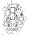
- the bit holding mechanism 151 for holding the hammer bit 119 inserted into the tool holder 137 is described with reference to FIGS. 2 and 3 .
- the bit holding mechanism 151 mainly includes the tool holder 137 having a bit holding hole 137a which has a circular section and into which a shank 119a of the hammer bit 119 is removably inserted, an engagement member in the form of a plurality of steel balls 153 which prevent or allow removal of the hammer bit 119 inserted into the bit holding hole 137a, and a tool sleeve 155 that switches the steel balls 153 between a bit removal preventing position and a bit removal allowing position.
- the tool holder 137 has a bit holding part 137A through which the bit holding hole 137a is formed in the axial direction and an impact bolt housing part 137B in which a space for housing the impact bolt 145 is formed.
- the impact bolt housing part 137B is integrally formed with the bit holding part 137A on its rear in the axial direction.
- the impact bolt housing part 137B is connected to the above-described sleeve 135 so that the tool holder 137 rotates together with the sleeve 135.
- the tool holder 137 and the sleeve 135 may be formed in one piece.
- the bit holding part 137A of the tool holder 137 is a feature that corresponds to the "bit holding region" according to this invention.
- the bit holding hole 137a has an open front end as a bit insertion opening and a rear end open to the space of the impact bolt housing part 137B.
- a plurality of slots 137b are formed through the bit holding part 137A of the tool holder 137 in the radial direction.
- the slots 137b have a predetermined length extending in the axial direction of the bit holding part 137A and are arranged at predetermined intervals in the circumferential direction of the bit holding part 137A.
- the steel balls 153 are each disposed in the associated slots 137b. Each of the steel balls 153 can move in the associated slot 137b in the axial direction and can be moved (displaced) in the radial direction of the bit holding part 137A.
- the slot 137b is a feature that corresponds to the "opening" according to this invention.
- the tool sleeve 155 is fitted on the bit holding part 137A such that it can move in the axial direction of the hammer bit.
- a stopper ring 157 for preventing the steel balls 153 from being displaced radially outward is fitted in the inside of the tool sleeve 155 on the bit holding part 137A.
- a stopper plate 159 is disposed on the rear of the stopper ring 157 such that it can move in the axial direction of the tool sleeve 155 with respect to the tool sleeve 155.
- the stopper plate 159 is pressed against a rear surface of the stopper ring 157 by a biasing spring 161 disposed between the tool sleeve 155 and the bit holding part 137A.
- the biasing force of the biasing spring 161 acts as a force of pushing the tool sleeve 155 forward. Therefore, the tool sleeve 155 is normally held in a position in which its front end is in contact with a cap 163 fitted over a front end portion of the bit holding part 137A, or in a bit removal preventing position.
- the engagement groove 119b of the hammer bit 119 has a predetermined length extending in the axial direction.
- a plurality of radially extending projections 137c are formed as a torque transmitting part on the inner surface of the bit holding hole 137a of the bit holding part 137A and arranged at predetermined intervals in the circumferential direction.
- the torque transmitting projections 137c have a predetermined length extending in the axial direction of the bit holding part 137A and fitted (engaged) in torque transmission grooves 119c (see FIG. 3 ) formed in the outer surface of the shank 119a of the hammer bit 119 which is inserted into the bit holding hole 137a. In this state, the rotating force of the bit holding part 137A is transmitted to the hammer bit 119.
- the torque transmission grooves 119c are open to a rear end of the shaft 119a such that they are used to position the hammer bit 119 in the circumferential direction when inserting the hammer bit 119 into the bit holding hole 137a.
- the bit holding mechanism 151 holds the hammer bit 119 in the bit holding hole 137a of the tool holder 137 while allowing the hammer bit 119 to move in the axial direction.
- the tool sleeve 155 In order to remove the hammer bit 119 from the bit holding part 137A, the tool sleeve 155 is moved to the rear bit removal allowing position against the biasing force of the biasing spring 161. As a result, the stopper ring 157 is released from the steel balls 153, so that the steel balls 153 are no longer prevented from moving radially outward. In this state, when the hammer bit 119 is pulled forward, the steel balls 153 are pushed radially outward. Therefore, the hammer bit 119 can be removed from the bit holding hole 137a.
- Holding rings 165, 167 are press-fitted into the bit holding part 137A of the tool holder 137 on the bit insertion opening side of the bit holding hole 137a and on the far side of the bit holding hole 137a in the bit inserting direction or the side adjacent to the impact bolt housing part 137B, respectively.
- the holding rings 165, 167 are formed of materials having a higher hardness than the bit holding part 137A, such as alloy tool steels (SKD), high speed tool steels (SKH) and high-carbon chrome bearing steels (SUJ), having a hardness of 60 Rockwell Hardness C-Scale (HRC) or higher.
- the holding ring 165 on the bit insertion opening side is provided as a region for holding the hammer bit 119 inserted into the bit holding hole 137a, while allowing the hammer bit 119 to move in the axial direction with respect to the bit holding hole 137a.
- the holding ring 167 on the far side in the bit inserting direction is provided as a region for holding an inserted end of the hammer bit 119 inserted into the bit holding hole 137a, while allowing it to move in the axial direction with respect to the bit holding hole 137a.
- a region between the two holding rings 165, 167 is provided as a region to dispose a mechanism for preventing removal of the hammer bit 119 and a mechanism for transmitting a rotational driving force of the tool holder 137 to the hammer bit 119.
- the hardnesses of a bit insertion opening side inner wall surface 165a and a far side inner wall surface 167a are higher than that of an intermediate inner wall surface 166a between the bit insertion opening side inner wall surface 165a and the far side inner wall surface 167a.
- the bit insertion opening side inner wall surface 165a, the far side inner wall surface 167a and the intermediate inner wall surface 166a are features that correspond to the "first holding region", the "third holding region” and the "second holding region", respectively, according to this invention.
- the hammer drill 101 is thus constructed.
- the bit insertion opening side inner wall surface 165a is located in an environment in which wear most easily occurs because dust generated during operation easily enters it.
- the bit insertion opening side inner wall surface 165a susceptible to wear is formed by the holding ring 165 having a higher hardness (of 60 Rockwell Hardness C-Scale (HRC) or higher), so that wear resistance of the bit insertion opening side inner wall surface 165a is increased.
- HRC Rockwell Hardness C-Scale
- the hammer bit 119 when the hammer bit 119 performs a striking movement during operation, the hammer bit 119 is acted upon not only by a reaction force from the workpiece in the axial direction, but by an external force including a radial component in a radial direction transverse to the axial direction.
- the inner wall surface of the bit holding hole 137a supports this transverse force acting upon the hammer bit 119 mainly on the bit insertion opening side inner wall surface 165a and the far side inner wall surface 167a.
- portions that are subjected to the above-described transverse force, or the bit insertion opening side inner wall surface 165a and the far side inner wall surface 167a, are formed by the holding rings 165, 167 having a higher hardness.
- the bit insertion opening side inner wall surface 165a and the far side inner wall surface 167a which are subjected to higher load can have a higher durability, so that wear of the inner wall surfaces 165a, 167a can be reduced in a rational
- Wear of the inner wall surface of the bit holding hole 137a may cause runout of the hammer bit 119. Then, particularly in the case of the hammer drill 101, in which the rotating force of the tool holder 137 is transmitted to the hammer bit 119, the torque transmitting projections 137c formed on the tool holder 137 may suffer wear. As a result, drilling or other operation may become difficult due to the runout of the hammer bit 119.
- the inner wall surface of the bit holding hole 137a is formed by a sleeve having a higher hardness along its entire axial length
- an axial impact force which acts upon a front end region (left end region as viewed in FIG. 2 ) of the slots 137b of the bit holding part 137A via the steel balls 153 during striking movement of the hammer bit 119 may produce cracks in the bit holding part 137A in the vicinity of the front end region due to its higher hardness.
- the machinability in forming the slots 137b of the bit holding part 137A by machining may be reduced.
- the bit holding part 137A forming the intermediate inner wall surface 166a can have as high a hardness as in a conventional technique. Therefore, the above-described problems of cracks and reduction in machinability can be solved. Further, in this embodiment, the bit holding hole 137a having the inner wall surface of different hardnesses can be easily produced by press-fitting the holding rings 165, 167 having a higher hardness than the bit holding part 137A, into the bit holding hole 137a on the bit insertion opening side and on the far side, respectively.
- the holding rings 165, 167 are described as being provided in the bit holding hole 137a on the bit insertion opening side and on the far side, respectively, it may be changed such that the holding ring 165 is provided only on the bit insertion opening side. Further, the holding rings 165, 167 may be fixed by means other than press fitting, such as by welding and by using screws.
Abstract
Description
- The present invention relates to an impact tool in accordance with the preamble of claim 1 that performs a predetermined operation on a workpiece by a striking movement of a tool bit in its axial direction.
-
DE 93 20 653 U1 describes such a tool holder for a power tool.
In an impact tool, such as a hammer or a hammer drill, a shank of a hammer bit is held by a tool holder so as to be movable in an axial direction. For this purpose, a slight clearance large enough to allow insertion of the shank is provided between an inner wall surface of a bit holding hole of the tool holder and an outer surface of the shank of the hammer bit inserted into the bit holding hole. Therefore, during hammering or hammer drill operation on a workpiece such as concrete, concrete dust generated by the operation adheres to the outer surface of the shank of the hammer bit and enters the above-described clearance. The hammer bit then moves with respect to the tool holder with the dust existing therebetween. As a result, the inner wall surface of the bit holding hole of the tool holder wears, which causes runout of the hammer bit and thus makes the operation difficult. Accordingly,WO02/20224 - Typically, an impact tool is configured such that steel balls arranged on the tool holder prevent removal of a hammer bit inserted into a bit holding hole of a tool holder. Therefore, an axial impact force is applied from the hammer bit to the tool holder via the steel balls during striking movement of the hammer bit. Accordingly, in the above-described known technique in which a hard sleeve is formed along the entire length of the bit holding hole into which a shank of the hammer bit is inserted, the sleeve is acted upon by an impact force. The sleeve made of a hard material however may crack on impact due to its high hardness. Further, slots in which the steel balls are disposed are formed through the sleeve in the radial direction. It is however difficult to form the slots by machining because the sleeve is hard. Therefore, in the known impact tool, further improvements are required in durability and machinability.
- It is, accordingly, an object of the invention to provide an effective technique for improving the durability and machinability of a tool holder for holding a tool bit in an impact tool.
- The above-described object can be achieved by the claimed invention. The present invention provides an impact tool having the features of claim 1 which includes a tool holder having a bit holding hole. A tool bit is inserted into the bit holding hole and the tool bit is held so as to be movable in an axial direction to perform a predetermined operation on a workpiece at least by striking movement of the tool bit in an axial direction. The manner "at least by striking movement of the tool bit in an axial direction" here includes the manner of driving the tool bit only by striking movement, and the manner of driving the tool bit by combination of striking movement and rotation.
The impact tool according to this invention has a bit holding region which is held in contact with an outer surface of the tool bit inserted into the bit holding hole and which holds the tool bit such that the tool bit can move in the axial direction. The bit holding region has a first holding region, a second holding region and a third holding region, arranged in this order in the bit holding hole from the side of a bit insertion opening toward the far side from the opening. The first holding region is provided as a region for holding the tool bit inserted into the bit holding hole, while allowing the tool bit to move in the axial direction with respect to the bit holding hole. The second holding region is provided as a region to dispose a removal preventing member which engages with the tool bit and thereby prevents the tool bit from becoming slipped out of the bit holding hole. Further, the third holding region is provided as a region for holding an inserted end of the tool bit inserted into the bit holding hole, while allowing it to move in the axial direction with respect to the bit holding hole. The hardness of the first holding region is higher than that of the second holding region. The "hardness of the first holding region" is preferably set to a hardness of 60 Rockwell Hardness C-Scale (HRC) or higher, and the first holding region is suitably formed of alloy tool steels (SKD), high speed tool steels (SKH) or high-carbon chrome bearing steels (SUJ). - In connection with wear of the bit holding region for holding the tool bit, an area of the bit holding region which dust generated during operation easily enters, or an area on the bit insertion opening side, is located in an environment in which wear most easily occurs. According to this invention, the first holding region on the bit insertion opening side where wear most easily occurs has a higher hardness than the second holding region, so that wear resistance of the first holding region can be increased. Thus, wear of the first holding region can be reduced and its durability can be increased. Wear of the bit holding region causes runout of the tool bit. Then, for example, in the case of a hammer drill, in which the rotating force of the tool holder is transmitted to the tool bit, torque transmitting projections formed on the tool holder may suffer wear. As a result, operation using the hammer drill may become difficult due to the runout of the tool bit. According to this invention, wear of the first holding region is reduced, so that runout of the tool bit can be reduced and thus wear of the torque transmitting projections can also be reduced.
In the second holding region of the tool holder, a removal preventing member (for example, steel balls) is arranged and provided to prevent the tool bit inserted into the bit holding hole from becoming slipped out of the bit holding hole. Therefore, the tool holder is acted upon by an axial impact force via the removal preventing member during striking movement of the tool bit. According to this invention, in the bit holding region, the regions other than the first holding region preferably have as high a hardness as in a conventional technique. Specifically, the second holding region in which the removal preventing member is disposed can preferably have as high a hardness as in a conventional technique. Therefore, cracks which might be produced due to too high hardness can be prevented from being produced on impact during striking movement of the hammer bit. Moreover, the machinability in forming a radial through hole for receiving the removal preventing member in the second holding region, for example, by machining, is not impaired because the hardness of the second holding region can preferably be as high as in a conventional technique. - In one aspect of the present invention, the hardness of the third holding region is higher than that of the second holding region. Preferably, the "hardness of the third holding region" is equal to that of the first holding region. When the tool bit performs a striking movement during operation, the tool bit is acted upon not only by a reaction force from the workpiece in the axial direction, but by an external force in a direction transverse to the axial direction. The bit holding region supports this transverse force acting upon the tool bit particularly on the first and third holding regions. According to this invention, portions that are subjected to the above-described transverse force, or the first and third holding regions, are designed to have a higher hardness than the second holding region, so that wear of the first and third holding regions can be reduced and their durability can be increased. Further, by reduction of wear of the first and third holding regions, runout of the tool bit can be further prevented and thus, if the impact tool is embodies as a hammer drill, wear of the torque transmitting projections can be effectively reduced.
- In another aspect of the invention, at least the first holding region of the first and third holding regions is formed of a material having a higher hardness than the second holding region and as a separate member. The "separate member" in this invention typically represents a ring-like member. Further, the manner of being "formed" here typically represents the manner in which the ring-like member is press-fitted into the bore of the tool holder, but it also suitably includes manners other than press-fitting, such as fixing by screws or by welding. According to this invention, the bit holding hole having the bit holding region of different hardnesses in the axial direction can be easily produced by forming the first holding region as a separate member, so that ease of production can be enhanced.
- In another aspect of the invention, the removal preventing member in the second holding region prevents removal of the tool bit by moving in a radially inward direction of the bit holding hole and engaging with the tool bit, and allows removal of the tool bit by moving in a radially outward direction of the bit holding hole. Further, an opening is formed in the second holding region and the removal preventing member is disposed in the opening so as to be movable in the radial direction. According to this invention, the opening in which the removal preventing member is disposed is formed in the second holding region having a lower hardness than the first holding region. Therefore, the opening can be easily formed, for example, by machining, and thus the machinability can be increased.
- According to this invention, an effective technique for improving the durability and machinability of a tool holder for holding a tool bit in an impact tool is provided.
-
-
FIG. 1 is a sectional view showing an entire electric hammer drill according to an embodiment of the invention. -
FIG. 2 is a sectional view showing a bit removal preventing part of a hammer bit holding mechanism part. -
FIG. 3 is a sectional view showing a torque transmitting part of the hammer bit holding mechanism part.. - A representative embodiment of the present invention is now described with reference to
FIGS. 1 to 3 . In this embodiment, an electric hammer drill is explained as a representative example of an impact tool according to the present invention.FIG. 1 is a sectional side view showing an entireelectric hammer drill 101 according to this embodiment. As shown inFIG. 1 , thehammer drill 101 mainly includes abody 103 that forms an outer shell of thehammer drill 101, ahammer bit 119 detachably coupled to the tip end region (on the left side as viewed inFIG. 1 ) of thebody 103 via atool holder 137, and agrip 109 connected to thebody 103 on the side opposite to thehammer bit 119 and designed to be held by a user. Thehammer bit 119 is mounted such that it is allowed to reciprocate with respect to thetool holder 137 in its axial direction and prevented from rotating with respect to the tool holder in its circumferential direction. Thehammer bit 119 is a feature that corresponds to the "tool bit" according to the present invention. In the present embodiment, for the sake of convenience of explanation, the side of thehammer bit 119 is taken as the front side and the side of thegrip 109 as the rear side. - The
body 103 mainly includes amotor housing 105 that houses a drivingmotor 111, and agear housing 107 that houses amotion converting mechanism 113, apower transmitting mechanism 114 and astriking mechanism 115. Themotor housing 105 and thegear housing 107 are connected together, for example, by screws (not shown) - The rotating output of the driving
motor 111 is appropriately converted into linear motion via themotion converting mechanism 113 and transmitted to thestriking mechanism 115. Then, an impact force is generated in the axial direction of thehammer bit 119 via thestriking mechanism 115. Further, thepower transmitting mechanism 114 appropriately reduces the speed of the rotating output of the drivingmotor 111 and then transmits the rotating output as a rotating force to thehammer bit 119. As a result, thehammer bit 119 is caused to rotate in the circumferential direction. The drivingmotor 111 is driven when atrigger 117 on thegrip 109 is depressed. - The
motion converting mechanism 113 mainly includes adriving gear 121 that is disposed on a tip end (front end) of anarmature shaft 112 of the drivingmotor 111 and rotated in a vertical plane by the drivingmotor 111, a drivengear 123 that engages with thedriving gear 121, a rotating element 127 that rotates together with the drivengear 123 via anintermediate shaft 125, aswash plate 129 that is caused to swing in the axial direction of thehammer bit 119 by rotation of the rotating element 127, and acylindrical piston 141 that is caused to reciprocate by swinging movement of theswash plate 129. Theintermediate shaft 125 is arranged parallel (horizontally) to the axial direction of thehammer bit 119. The outer surface of the rotating element 127 that is fitted onto theintermediate shaft 125 is inclined at a predetermined angle with respect to the axis of theintermediate shaft 125. Theswash plate 129 is fitted on the inclined outer surface of the rotating element 127 via aball bearing 126 such that it can rotate with respect to the rotating element 127. Theswash plate 129 is caused to swing in the axial direction of thehammer bit 119 by rotation of the rotating element 127. Further, theswash plate 129 has a swingingrod 128 extending upward (in the radial direction) from theswash plate 129. The swingingrod 128 is connected to a rear end of thecylindrical piston 141 via a connectingshaft 124 such that it can rotate with respect to thepiston 141. Thecylindrical piston 141 is slidably disposed within asleeve 135 that is disposed within thegear housing 107, and the rear end of the bore of the piston is closed. - The
power transmitting mechanism 114 mainly includes afirst transmission gear 131 that is caused to rotate in a vertical plane by the drivingmotor 111 via thedriving gear 121 and theintermediate shaft 125, asecond transmission gear 133 that engages with thefirst transmission gear 131, asleeve 135 that is caused to rotate together with thesecond transmission gear 133, and atool holder 137 that is caused to rotate together with thesleeve 135 in a vertical plane. - As shown in
FIG. 1 , thestriking element 115 mainly includes thecylindrical piston 141, astriker 143 slidably disposed within the bore of thecylindrical piston 141, and animpact bolt 145 that is slidably disposed within thetool holder 137 and serves to transmit the kinetic energy of thestriker 143 to thehammer bit 119. - In the
hammer drill 101 thus constructed, when the drivingmotor 111 is driven by the user's depressing operation of thetrigger 117, thedriving gear 121 is caused to rotate in a vertical plane by the rotating output of the drivingmotor 111. Then, the rotating element 127 is caused to rotate in a vertical plane via the drivengear 123 that engages with thedriving gear 121 and via theintermediate shaft 125. Thus, theswash plate 129 and the swingingrod 128 are then caused to swing in the axial direction of thehammer bit 119, which in turn causes thecylindrical piston 141 to slide linearly. Thestriker 143 is then caused to linearly move within thepiston 141 by pressure fluctuations of air or the action of an air spring within an air chamber 141 a of thecylindrical piston 141 as a result of the sliding movement of thepiston 141. Thestriker 143 then collides with theimpact bolt 145 and transmits the kinetic energy to thehammer bit 119. - When the
first transmission gear 131 rotates together with theintermediate shaft 125, thesleeve 135 is caused to rotate in a vertical plane via thesecond transmission gear 133 that engages with thefirst transmission gear 131. Further, thetool holder 137 and thehammer bit 119 supported by thetool holder 137 rotate together with thesleeve 135. Thus, thehammer bit 119 performs a drilling operation on a workpiece (concrete) by a hammering movement in the axial direction and a drilling movement in the circumferential direction. - The
hammer drill 101 according to this embodiment can be switched between a hammer drill mode in which thehammer bit 119 is caused to perform a hammering movement and a drilling movement as described above and a drill mode in which thehammer bit 119 is caused to perform only a drilling movement. A mechanism for such mode changing is not directly related to this invention and therefore will not be described. - Now, a
bit holding mechanism 151 for holding thehammer bit 119 inserted into thetool holder 137 is described with reference toFIGS. 2 and3 . Thebit holding mechanism 151 mainly includes thetool holder 137 having a bit holding hole 137a which has a circular section and into which a shank 119a of thehammer bit 119 is removably inserted, an engagement member in the form of a plurality ofsteel balls 153 which prevent or allow removal of thehammer bit 119 inserted into the bit holding hole 137a, and atool sleeve 155 that switches thesteel balls 153 between a bit removal preventing position and a bit removal allowing position. Thetool holder 137 has abit holding part 137A through which the bit holding hole 137a is formed in the axial direction and an impactbolt housing part 137B in which a space for housing theimpact bolt 145 is formed. The impactbolt housing part 137B is integrally formed with thebit holding part 137A on its rear in the axial direction. The impactbolt housing part 137B is connected to the above-describedsleeve 135 so that thetool holder 137 rotates together with thesleeve 135. Thetool holder 137 and thesleeve 135 may be formed in one piece. Thebit holding part 137A of thetool holder 137 is a feature that corresponds to the "bit holding region" according to this invention. - The bit holding hole 137a has an open front end as a bit insertion opening and a rear end open to the space of the impact
bolt housing part 137B. A plurality ofslots 137b are formed through thebit holding part 137A of thetool holder 137 in the radial direction. Theslots 137b have a predetermined length extending in the axial direction of thebit holding part 137A and are arranged at predetermined intervals in the circumferential direction of thebit holding part 137A. Thesteel balls 153 are each disposed in the associatedslots 137b. Each of thesteel balls 153 can move in the associatedslot 137b in the axial direction and can be moved (displaced) in the radial direction of thebit holding part 137A. Theslot 137b is a feature that corresponds to the "opening" according to this invention. - The
tool sleeve 155 is fitted on thebit holding part 137A such that it can move in the axial direction of the hammer bit. Astopper ring 157 for preventing thesteel balls 153 from being displaced radially outward is fitted in the inside of thetool sleeve 155 on thebit holding part 137A. Further, astopper plate 159 is disposed on the rear of thestopper ring 157 such that it can move in the axial direction of thetool sleeve 155 with respect to thetool sleeve 155. Thestopper plate 159 is pressed against a rear surface of thestopper ring 157 by a biasingspring 161 disposed between thetool sleeve 155 and thebit holding part 137A. The biasing force of the biasingspring 161 acts as a force of pushing thetool sleeve 155 forward. Therefore, thetool sleeve 155 is normally held in a position in which its front end is in contact with acap 163 fitted over a front end portion of thebit holding part 137A, or in a bit removal preventing position. - In this state, when the shank 119a of the
hammer bit 119 is inserted into the bit holding hole 137a of thebit holding part 137A, thesteel balls 153 are pushed rearward by the rear end of the shank 119a of thehammer bit 119. Then, thesteel balls 153 move radially outward while pushing thestopper plate 159 rearward against the biasing force of the biasingspring 161, which allows further insertion of thehammer bit 119. When the rear end of the shank 119a of thehammer bit 119 passes thesteel balls 153, thesteel balls 153 are moved radially inward via thestopper plate 159 by the biasing force of the biasingspring 161 and engaged with anengagement groove 119b formed in the outer surface of the shank of thehammer bit 119, so that removal of thehammer bit 119 is prevented. Theengagement groove 119b of thehammer bit 119 has a predetermined length extending in the axial direction. - Further, a plurality of radially extending
projections 137c are formed as a torque transmitting part on the inner surface of the bit holding hole 137a of thebit holding part 137A and arranged at predetermined intervals in the circumferential direction. Thetorque transmitting projections 137c have a predetermined length extending in the axial direction of thebit holding part 137A and fitted (engaged) in torque transmission grooves 119c (seeFIG. 3 ) formed in the outer surface of the shank 119a of thehammer bit 119 which is inserted into the bit holding hole 137a. In this state, the rotating force of thebit holding part 137A is transmitted to thehammer bit 119. The torque transmission grooves 119c are open to a rear end of the shaft 119a such that they are used to position thehammer bit 119 in the circumferential direction when inserting thehammer bit 119 into the bit holding hole 137a. Thus, thebit holding mechanism 151 holds thehammer bit 119 in the bit holding hole 137a of thetool holder 137 while allowing thehammer bit 119 to move in the axial direction. - In order to remove the
hammer bit 119 from thebit holding part 137A, thetool sleeve 155 is moved to the rear bit removal allowing position against the biasing force of the biasingspring 161. As a result, thestopper ring 157 is released from thesteel balls 153, so that thesteel balls 153 are no longer prevented from moving radially outward. In this state, when thehammer bit 119 is pulled forward, thesteel balls 153 are pushed radially outward. Therefore, thehammer bit 119 can be removed from the bit holding hole 137a. - Holding rings 165, 167 are press-fitted into the
bit holding part 137A of thetool holder 137 on the bit insertion opening side of the bit holding hole 137a and on the far side of the bit holding hole 137a in the bit inserting direction or the side adjacent to the impactbolt housing part 137B, respectively. The holding rings 165, 167 are formed of materials having a higher hardness than thebit holding part 137A, such as alloy tool steels (SKD), high speed tool steels (SKH) and high-carbon chrome bearing steels (SUJ), having a hardness of 60 Rockwell Hardness C-Scale (HRC) or higher. The holdingring 165 on the bit insertion opening side is provided as a region for holding thehammer bit 119 inserted into the bit holding hole 137a, while allowing thehammer bit 119 to move in the axial direction with respect to the bit holding hole 137a. The holdingring 167 on the far side in the bit inserting direction is provided as a region for holding an inserted end of thehammer bit 119 inserted into the bit holding hole 137a, while allowing it to move in the axial direction with respect to the bit holding hole 137a. A region between the two holdingrings hammer bit 119 and a mechanism for transmitting a rotational driving force of thetool holder 137 to thehammer bit 119. - As described above, in this embodiment, as for the inner wall surface of the bit holding hole 137a which contacts the outer surface of the shank 119a of the
hammer bit 119, the hardnesses of a bit insertion opening sideinner wall surface 165a and a far side inner wall surface 167a are higher than that of an intermediate inner wall surface 166a between the bit insertion opening sideinner wall surface 165a and the far side inner wall surface 167a. The bit insertion opening sideinner wall surface 165a, the far side inner wall surface 167a and the intermediate inner wall surface 166a are features that correspond to the "first holding region", the "third holding region" and the "second holding region", respectively, according to this invention. Theslots 137b in which thesteel balls 153 are disposed as a removal preventing member, and thetorque transmitting projections 137c are formed in thebit holding part 137A which forms the intermediate inner wall surface 166a between the bit insertion opening sideinner wall surface 165a and the far side inner wall surface 167a. - The
hammer drill 101 according to this invention is thus constructed. In the inner wall surface of the bit holding hole 137a into which the shank 119a of thehammer bit 119 is inserted, the bit insertion opening sideinner wall surface 165a is located in an environment in which wear most easily occurs because dust generated during operation easily enters it. In this embodiment, in the inner wall surface of the bit holding hole 137a, the bit insertion opening sideinner wall surface 165a susceptible to wear is formed by the holdingring 165 having a higher hardness (of 60 Rockwell Hardness C-Scale (HRC) or higher), so that wear resistance of the bit insertion opening sideinner wall surface 165a is increased. Thus, wear of the bit insertion opening sideinner wall surface 165 can be reduced and its durability can be increased. - Further, when the
hammer bit 119 performs a striking movement during operation, thehammer bit 119 is acted upon not only by a reaction force from the workpiece in the axial direction, but by an external force including a radial component in a radial direction transverse to the axial direction. The inner wall surface of the bit holding hole 137a supports this transverse force acting upon thehammer bit 119 mainly on the bit insertion opening sideinner wall surface 165a and the far side inner wall surface 167a. According to this embodiment, portions that are subjected to the above-described transverse force, or the bit insertion opening sideinner wall surface 165a and the far side inner wall surface 167a, are formed by the holding rings 165, 167 having a higher hardness. Thus, the bit insertion opening sideinner wall surface 165a and the far side inner wall surface 167a which are subjected to higher load can have a higher durability, so that wear of theinner wall surfaces 165a, 167a can be reduced in a rational manner. - Wear of the inner wall surface of the bit holding hole 137a may cause runout of the
hammer bit 119. Then, particularly in the case of thehammer drill 101, in which the rotating force of thetool holder 137 is transmitted to thehammer bit 119, thetorque transmitting projections 137c formed on thetool holder 137 may suffer wear. As a result, drilling or other operation may become difficult due to the runout of thehammer bit 119. According to this embodiment, as described above, in the inner wall surface of the bit holding hole 137a, wear of the bit insertion opening sideinner wall surface 165a and the far side inner wall surface 167a is reduced, so that runout of thehammer bit 119 can be reduced and thus wear of thetorque transmitting projections 137c can also be reduced. - If the inner wall surface of the bit holding hole 137a is formed by a sleeve having a higher hardness along its entire axial length, an axial impact force which acts upon a front end region (left end region as viewed in
FIG. 2 ) of theslots 137b of thebit holding part 137A via thesteel balls 153 during striking movement of thehammer bit 119 may produce cracks in thebit holding part 137A in the vicinity of the front end region due to its higher hardness. Moreover, in this case, the machinability in forming theslots 137b of thebit holding part 137A by machining may be reduced. According to this embodiment, however, in the inner wall surface of the bit holding hole 137a, thebit holding part 137A forming the intermediate inner wall surface 166a can have as high a hardness as in a conventional technique. Therefore, the above-described problems of cracks and reduction in machinability can be solved. Further, in this embodiment, the bit holding hole 137a having the inner wall surface of different hardnesses can be easily produced by press-fitting the holding rings 165, 167 having a higher hardness than thebit holding part 137A, into the bit holding hole 137a on the bit insertion opening side and on the far side, respectively. - Further, although, in this embodiment, the holding rings 165, 167 are described as being provided in the bit holding hole 137a on the bit insertion opening side and on the far side, respectively, it may be changed such that the holding
ring 165 is provided only on the bit insertion opening side. Further, the holding rings 165, 167 may be fixed by means other than press fitting, such as by welding and by using screws. -
- 101 hammer drill (impact tool)
- 103 body
- 105 motor housing
- 107 gear housing
- 109 grip
- 111 driving motor
- 112 armature shaft
- 113 motion converting mechanism
- 115 striking mechanism
- 117 trigger
- 119 hammer bit (tool bit)
- 119a shank
- 119b engagement groove
- 119c torque transmission groove
- 121 driving gear
- 123 driven gear
- 124 connecting shaft
- 125 intermediate shaft
- 126 ball bearing
- 127 rotating element
- 128 swinging rod
- 129 swash plate
- 131 first transmission gear
- 133 second transmission gear
- 135 sleeve
- 137 tool holder
- 137A bit holding part (bit holding region, second holding region)
- 137B impact bolt housing part
- 137a bit holding hole
- 137b slot (opening)
- 137c torque transmitting projection
- 141 cylindrical piston
- 141 a air chamber
- 143 striker
- 145 impact bolt
- 151 bit holding mechanism
- 153 steel ball
- 155 tool sleeve
- 157 stopper ring
- 159 stopper plate
- 161 biasing spring
- 163 cap
- 165 holding ring on the bit insertion opening side
- 165a bit insertion opening side inner wall surface (first holding region)
- 166a intermediate inner wall surface (second holding region)
- 167 holding ring on the far side in the bit inserting direction
- 167a far side inner wall surface (third holding region)
Claims (6)
- An impact tool which includes a tool holder (137) having a bit holding hole, (137a) wherein a detachably coupled tool bit (119) is inserted into the bit holding hole (137a), the tool bit (119) movably held in an axial direction to perform a predetermined operation on a workpiece at least by striking movement of the tool bit (119) in an axial direction, wherein the tool holder (137) has a bit holding region (137A) which is held in contact with an outer surface of the tool bit (119) inserted into the bit holding hole (137a), the tool holder (137) holding the tool bit (119) such that the tool bit can move in the axial direction and,
wherein the bit holding region (137A) has a first holding region (165a), a second holding region (166a) and a third holding region (167a), arranged in this order in the bit holding hole (137a) from a bit insertion opening toward the far side from the opening and,
wherein the first holding region (165a) is provided as a region for holding the tool bit (119) inserted into the bit holding hole (137a), while allowing the tool bit (119) to move in the axial direction with respect to the bit holding hole (137a), the second holding region (166a) is provided as a region to dispose a removal preventing member (153) which enrages with the tool bit (119) and thereby prevents the tool bit (119) from becoming slipped out of the bit holding hole (137a), and the third holding region (167a) is provided as a region for holding an inserted end of the tool bit (119) inserted into the bit holding hole (137a), while allowing it to move in the axial direction with respect to the bit holding hole (137a),
wherein the hardness of the first holding region (165a) or the hardnesses of the first and third holding regions (165a, 167a) are higher than that of the second holding region (166a)
characterized in that a rotatting force of the bit holding region (137A) is transmitted to the tool bit (119) via the second holding region (166a). - The impact tool as defined in claim 1, wherein the first holding region (165a) or the first and third holding regions (165a, 167a) are formed by a separate member having a higher hardness than the second holding region (166a).
- The impact tool as defined in claim 1 or 2, wherein:a ring-like member (165) is mounted to the tool holder (137), the ring-like member (165) being formed of a material having a higher hardness than the second holding region (166a) and separately from the tool holder (137), andan inner circumferential surface of the ring-like member (165) mounted to the tool holder (137) forms the first holding region (165a).
- The impact tool as defined in claim 3, wherein:in addition to the ring-like member (165), a second ring-like member (167) is mounted to the tool holder (137), the second ring-like member (167) being formed of a material having a higher hardness than the second holding region (166a) and separately from the tool holder (137), andan inner circumferential surface of the second ring-like member (167) mounted to the tool holder (137) forms the third holding region (167a).
- The impact tool as defined in claim 3 or 4, wherein one or both of the ring-like members (165, 167) are mounted to the tool holder (137) by press fitting.
- The impact tool as defined in any one of claims 1 to 5, wherein the removal preventing member (153) in the second holding region (166a) prevents removal of the tool bit (119) by moving in a radially inward direction of the bit holding hole (137a) and engaging with the tool bit (119), and allows removal of the tool bit (119) by moving in a radially outward direction of the bit holding hole (137a), and wherein an opening (137b) is formed in the second holding region (166a) and the removal preventing member (153) is disposed in the opening (137b) so as to be movable in the radial direction.
Applications Claiming Priority (2)
| Application Number | Priority Date | Filing Date | Title |
|---|---|---|---|
| JP2006316087A JP2008126378A (en) | 2006-11-22 | 2006-11-22 | Hammering tool |
| PCT/JP2007/072594 WO2008062851A1 (en) | 2006-11-22 | 2007-11-21 | Percussion tool |
Publications (3)
| Publication Number | Publication Date |
|---|---|
| EP2085190A1 EP2085190A1 (en) | 2009-08-05 |
| EP2085190A4 EP2085190A4 (en) | 2011-02-16 |
| EP2085190B1 true EP2085190B1 (en) | 2012-02-01 |
Family
ID=39429782
Family Applications (1)
| Application Number | Title | Priority Date | Filing Date |
|---|---|---|---|
| EP07832324A Not-in-force EP2085190B1 (en) | 2006-11-22 | 2007-11-21 | Percussion tool |
Country Status (4)
| Country | Link |
|---|---|
| EP (1) | EP2085190B1 (en) |
| JP (1) | JP2008126378A (en) |
| AT (1) | ATE543613T1 (en) |
| WO (1) | WO2008062851A1 (en) |
Families Citing this family (3)
| Publication number | Priority date | Publication date | Assignee | Title |
|---|---|---|---|---|
| JP4597262B1 (en) * | 2010-04-15 | 2010-12-15 | 正義 嶋本 | Slide hammer with tip tool |
| US8068011B1 (en) | 2010-08-27 | 2011-11-29 | Q Street, LLC | System and method for interactive user-directed interfacing between handheld devices and RFID media |
| DE102020213165A1 (en) * | 2020-10-19 | 2022-04-21 | Robert Bosch Gesellschaft mit beschränkter Haftung | Hand tool machine with a locking device |
Family Cites Families (9)
| Publication number | Priority date | Publication date | Assignee | Title |
|---|---|---|---|---|
| US3168324A (en) * | 1963-02-15 | 1965-02-02 | Ingersoll Rand Co | Chuck |
| US4332300A (en) * | 1979-06-14 | 1982-06-01 | Rensselear Polytechnic Institute | Pneumatic hammer nozzle seal |
| JPS62150077U (en) * | 1986-03-14 | 1987-09-22 | ||
| DE3637354A1 (en) * | 1986-11-03 | 1988-05-05 | Bosch Gmbh Robert | Tool holder |
| FR2692187B1 (en) * | 1992-06-16 | 1997-06-20 | Montabert Ets | DEVICE FOR HOLDING THE TOOL OF A HYDRAULIC ROCK BREAKER. |
| DE9320653U1 (en) * | 1993-10-28 | 1995-02-23 | Bosch Gmbh Robert | Tool holder on hand machine tools for hammer drills |
| JPH07299767A (en) * | 1994-04-28 | 1995-11-14 | Hitachi Koki Co Ltd | Hammering tool |
| KR200151343Y1 (en) * | 1995-04-14 | 1999-07-15 | 최해성 | The hydraulic hammer of low noise type |
| DE10044387A1 (en) | 2000-09-08 | 2002-04-04 | Bosch Gmbh Robert | Tool holder for a hand machine tool |
-
2006
- 2006-11-22 JP JP2006316087A patent/JP2008126378A/en active Pending
-
2007
- 2007-11-21 AT AT07832324T patent/ATE543613T1/en active
- 2007-11-21 EP EP07832324A patent/EP2085190B1/en not_active Not-in-force
- 2007-11-21 WO PCT/JP2007/072594 patent/WO2008062851A1/en active Application Filing
Also Published As
| Publication number | Publication date |
|---|---|
| WO2008062851A1 (en) | 2008-05-29 |
| JP2008126378A (en) | 2008-06-05 |
| EP2085190A1 (en) | 2009-08-05 |
| EP2085190A4 (en) | 2011-02-16 |
| ATE543613T1 (en) | 2012-02-15 |
Similar Documents
| Publication | Publication Date | Title |
|---|---|---|
| EP1808272B1 (en) | Power tool comprising a torque limiter | |
| EP2199030B1 (en) | Impact tool | |
| EP1741520B1 (en) | Motor support structure of a power tool | |
| US7077217B2 (en) | Hammer | |
| EP2390049B1 (en) | Impact Tool | |
| EP1602451B1 (en) | Rotary spindle for power tool and power tool incorporating such spindle | |
| EP2529892B1 (en) | Power tool | |
| EP1375076B1 (en) | Percussion hammer | |
| EP2085190B1 (en) | Percussion tool | |
| CN103182549A (en) | Handheld tool apparatus | |
| CN101228008A (en) | Percussion mechanism and at least percussively-operated hand machine tool with a percussion mechanism | |
| EP1438160B1 (en) | Hammer | |
| GB2381228A (en) | Electrically powered hammer with support bearing | |
| US6810969B2 (en) | Hand machine tool | |
| CN103182548A (en) | Hand-held tool device | |
| JP2008126378A5 (en) | ||
| JP2006181664A (en) | Hammer drill | |
| US20240009823A1 (en) | Rotary hammer | |
| CN213673949U (en) | Impact tool | |
| JP2007326168A (en) | Work tool | |
| JP2017042888A (en) | Impact tool |
Legal Events
| Date | Code | Title | Description |
|---|---|---|---|
| PUAI | Public reference made under article 153(3) epc to a published international application that has entered the european phase |
Free format text: ORIGINAL CODE: 0009012 |
|
| 17P | Request for examination filed |
Effective date: 20090529 |
|
| AK | Designated contracting states |
Kind code of ref document: A1 Designated state(s): AT BE BG CH CY CZ DE DK EE ES FI FR GB GR HU IE IS IT LI LT LU LV MC MT NL PL PT RO SE SI SK TR |
|
| DAX | Request for extension of the european patent (deleted) | ||
| A4 | Supplementary search report drawn up and despatched |
Effective date: 20110113 |
|
| GRAP | Despatch of communication of intention to grant a patent |
Free format text: ORIGINAL CODE: EPIDOSNIGR1 |
|
| GRAS | Grant fee paid |
Free format text: ORIGINAL CODE: EPIDOSNIGR3 |
|
| GRAA | (expected) grant |
Free format text: ORIGINAL CODE: 0009210 |
|
| AK | Designated contracting states |
Kind code of ref document: B1 Designated state(s): AT BE BG CH CY CZ DE DK EE ES FI FR GB GR HU IE IS IT LI LT LU LV MC MT NL PL PT RO SE SI SK TR |
|
| REG | Reference to a national code |
Ref country code: GB Ref legal event code: FG4D |
|
| REG | Reference to a national code |
Ref country code: AT Ref legal event code: REF Ref document number: 543613 Country of ref document: AT Kind code of ref document: T Effective date: 20120215 Ref country code: CH Ref legal event code: EP |
|
| REG | Reference to a national code |
Ref country code: DE Ref legal event code: R096 Ref document number: 602007020486 Country of ref document: DE Effective date: 20120329 |
|
| REG | Reference to a national code |
Ref country code: NL Ref legal event code: VDEP Effective date: 20120201 |
|
| LTIE | Lt: invalidation of european patent or patent extension |
Effective date: 20120201 |
|
| PG25 | Lapsed in a contracting state [announced via postgrant information from national office to epo] |
Ref country code: NL Free format text: LAPSE BECAUSE OF FAILURE TO SUBMIT A TRANSLATION OF THE DESCRIPTION OR TO PAY THE FEE WITHIN THE PRESCRIBED TIME-LIMIT Effective date: 20120201 Ref country code: LT Free format text: LAPSE BECAUSE OF FAILURE TO SUBMIT A TRANSLATION OF THE DESCRIPTION OR TO PAY THE FEE WITHIN THE PRESCRIBED TIME-LIMIT Effective date: 20120201 Ref country code: IS Free format text: LAPSE BECAUSE OF FAILURE TO SUBMIT A TRANSLATION OF THE DESCRIPTION OR TO PAY THE FEE WITHIN THE PRESCRIBED TIME-LIMIT Effective date: 20120601 |
|
| PG25 | Lapsed in a contracting state [announced via postgrant information from national office to epo] |
Ref country code: PT Free format text: LAPSE BECAUSE OF FAILURE TO SUBMIT A TRANSLATION OF THE DESCRIPTION OR TO PAY THE FEE WITHIN THE PRESCRIBED TIME-LIMIT Effective date: 20120601 Ref country code: FI Free format text: LAPSE BECAUSE OF FAILURE TO SUBMIT A TRANSLATION OF THE DESCRIPTION OR TO PAY THE FEE WITHIN THE PRESCRIBED TIME-LIMIT Effective date: 20120201 Ref country code: GR Free format text: LAPSE BECAUSE OF FAILURE TO SUBMIT A TRANSLATION OF THE DESCRIPTION OR TO PAY THE FEE WITHIN THE PRESCRIBED TIME-LIMIT Effective date: 20120502 Ref country code: BE Free format text: LAPSE BECAUSE OF FAILURE TO SUBMIT A TRANSLATION OF THE DESCRIPTION OR TO PAY THE FEE WITHIN THE PRESCRIBED TIME-LIMIT Effective date: 20120201 Ref country code: PL Free format text: LAPSE BECAUSE OF FAILURE TO SUBMIT A TRANSLATION OF THE DESCRIPTION OR TO PAY THE FEE WITHIN THE PRESCRIBED TIME-LIMIT Effective date: 20120201 Ref country code: LV Free format text: LAPSE BECAUSE OF FAILURE TO SUBMIT A TRANSLATION OF THE DESCRIPTION OR TO PAY THE FEE WITHIN THE PRESCRIBED TIME-LIMIT Effective date: 20120201 |
|
| REG | Reference to a national code |
Ref country code: AT Ref legal event code: MK05 Ref document number: 543613 Country of ref document: AT Kind code of ref document: T Effective date: 20120201 |
|
| PG25 | Lapsed in a contracting state [announced via postgrant information from national office to epo] |
Ref country code: CY Free format text: LAPSE BECAUSE OF FAILURE TO SUBMIT A TRANSLATION OF THE DESCRIPTION OR TO PAY THE FEE WITHIN THE PRESCRIBED TIME-LIMIT Effective date: 20120201 |
|
| PG25 | Lapsed in a contracting state [announced via postgrant information from national office to epo] |
Ref country code: EE Free format text: LAPSE BECAUSE OF FAILURE TO SUBMIT A TRANSLATION OF THE DESCRIPTION OR TO PAY THE FEE WITHIN THE PRESCRIBED TIME-LIMIT Effective date: 20120201 Ref country code: RO Free format text: LAPSE BECAUSE OF FAILURE TO SUBMIT A TRANSLATION OF THE DESCRIPTION OR TO PAY THE FEE WITHIN THE PRESCRIBED TIME-LIMIT Effective date: 20120201 Ref country code: SE Free format text: LAPSE BECAUSE OF FAILURE TO SUBMIT A TRANSLATION OF THE DESCRIPTION OR TO PAY THE FEE WITHIN THE PRESCRIBED TIME-LIMIT Effective date: 20120201 Ref country code: CZ Free format text: LAPSE BECAUSE OF FAILURE TO SUBMIT A TRANSLATION OF THE DESCRIPTION OR TO PAY THE FEE WITHIN THE PRESCRIBED TIME-LIMIT Effective date: 20120201 Ref country code: DK Free format text: LAPSE BECAUSE OF FAILURE TO SUBMIT A TRANSLATION OF THE DESCRIPTION OR TO PAY THE FEE WITHIN THE PRESCRIBED TIME-LIMIT Effective date: 20120201 Ref country code: SI Free format text: LAPSE BECAUSE OF FAILURE TO SUBMIT A TRANSLATION OF THE DESCRIPTION OR TO PAY THE FEE WITHIN THE PRESCRIBED TIME-LIMIT Effective date: 20120201 |
|
| PG25 | Lapsed in a contracting state [announced via postgrant information from national office to epo] |
Ref country code: SK Free format text: LAPSE BECAUSE OF FAILURE TO SUBMIT A TRANSLATION OF THE DESCRIPTION OR TO PAY THE FEE WITHIN THE PRESCRIBED TIME-LIMIT Effective date: 20120201 Ref country code: IT Free format text: LAPSE BECAUSE OF FAILURE TO SUBMIT A TRANSLATION OF THE DESCRIPTION OR TO PAY THE FEE WITHIN THE PRESCRIBED TIME-LIMIT Effective date: 20120201 |
|
| PLBE | No opposition filed within time limit |
Free format text: ORIGINAL CODE: 0009261 |
|
| STAA | Information on the status of an ep patent application or granted ep patent |
Free format text: STATUS: NO OPPOSITION FILED WITHIN TIME LIMIT |
|
| 26N | No opposition filed |
Effective date: 20121105 |
|
| PG25 | Lapsed in a contracting state [announced via postgrant information from national office to epo] |
Ref country code: AT Free format text: LAPSE BECAUSE OF FAILURE TO SUBMIT A TRANSLATION OF THE DESCRIPTION OR TO PAY THE FEE WITHIN THE PRESCRIBED TIME-LIMIT Effective date: 20120201 |
|
| REG | Reference to a national code |
Ref country code: DE Ref legal event code: R097 Ref document number: 602007020486 Country of ref document: DE Effective date: 20121105 |
|
| PG25 | Lapsed in a contracting state [announced via postgrant information from national office to epo] |
Ref country code: ES Free format text: LAPSE BECAUSE OF FAILURE TO SUBMIT A TRANSLATION OF THE DESCRIPTION OR TO PAY THE FEE WITHIN THE PRESCRIBED TIME-LIMIT Effective date: 20120512 |
|
| REG | Reference to a national code |
Ref country code: CH Ref legal event code: PL |
|
| PG25 | Lapsed in a contracting state [announced via postgrant information from national office to epo] |
Ref country code: CH Free format text: LAPSE BECAUSE OF NON-PAYMENT OF DUE FEES Effective date: 20121130 Ref country code: BG Free format text: LAPSE BECAUSE OF FAILURE TO SUBMIT A TRANSLATION OF THE DESCRIPTION OR TO PAY THE FEE WITHIN THE PRESCRIBED TIME-LIMIT Effective date: 20120501 Ref country code: LI Free format text: LAPSE BECAUSE OF NON-PAYMENT OF DUE FEES Effective date: 20121130 |
|
| REG | Reference to a national code |
Ref country code: IE Ref legal event code: MM4A |
|
| PG25 | Lapsed in a contracting state [announced via postgrant information from national office to epo] |
Ref country code: IE Free format text: LAPSE BECAUSE OF NON-PAYMENT OF DUE FEES Effective date: 20121121 |
|
| PG25 | Lapsed in a contracting state [announced via postgrant information from national office to epo] |
Ref country code: MT Free format text: LAPSE BECAUSE OF FAILURE TO SUBMIT A TRANSLATION OF THE DESCRIPTION OR TO PAY THE FEE WITHIN THE PRESCRIBED TIME-LIMIT Effective date: 20120201 |
|
| PGFP | Annual fee paid to national office [announced via postgrant information from national office to epo] |
Ref country code: DE Payment date: 20131113 Year of fee payment: 7 Ref country code: GB Payment date: 20131120 Year of fee payment: 7 Ref country code: FR Payment date: 20131108 Year of fee payment: 7 |
|
| PG25 | Lapsed in a contracting state [announced via postgrant information from national office to epo] |
Ref country code: TR Free format text: LAPSE BECAUSE OF FAILURE TO SUBMIT A TRANSLATION OF THE DESCRIPTION OR TO PAY THE FEE WITHIN THE PRESCRIBED TIME-LIMIT Effective date: 20120201 Ref country code: MC Free format text: LAPSE BECAUSE OF NON-PAYMENT OF DUE FEES Effective date: 20121130 |
|
| PG25 | Lapsed in a contracting state [announced via postgrant information from national office to epo] |
Ref country code: LU Free format text: LAPSE BECAUSE OF NON-PAYMENT OF DUE FEES Effective date: 20121121 |
|
| PG25 | Lapsed in a contracting state [announced via postgrant information from national office to epo] |
Ref country code: HU Free format text: LAPSE BECAUSE OF FAILURE TO SUBMIT A TRANSLATION OF THE DESCRIPTION OR TO PAY THE FEE WITHIN THE PRESCRIBED TIME-LIMIT Effective date: 20071121 |
|
| REG | Reference to a national code |
Ref country code: DE Ref legal event code: R119 Ref document number: 602007020486 Country of ref document: DE |
|
| GBPC | Gb: european patent ceased through non-payment of renewal fee |
Effective date: 20141121 |
|
| REG | Reference to a national code |
Ref country code: FR Ref legal event code: ST Effective date: 20150731 |
|
| PG25 | Lapsed in a contracting state [announced via postgrant information from national office to epo] |
Ref country code: DE Free format text: LAPSE BECAUSE OF NON-PAYMENT OF DUE FEES Effective date: 20150602 Ref country code: GB Free format text: LAPSE BECAUSE OF NON-PAYMENT OF DUE FEES Effective date: 20141121 |
|
| PG25 | Lapsed in a contracting state [announced via postgrant information from national office to epo] |
Ref country code: FR Free format text: LAPSE BECAUSE OF NON-PAYMENT OF DUE FEES Effective date: 20141201 |