EP2732846A1 - Guidewire - Google Patents
Guidewire Download PDFInfo
- Publication number
- EP2732846A1 EP2732846A1 EP13186793.9A EP13186793A EP2732846A1 EP 2732846 A1 EP2732846 A1 EP 2732846A1 EP 13186793 A EP13186793 A EP 13186793A EP 2732846 A1 EP2732846 A1 EP 2732846A1
- Authority
- EP
- European Patent Office
- Prior art keywords
- coil body
- distal
- guidewire
- bonding
- inner coil
- Prior art date
- Legal status (The legal status is an assumption and is not a legal conclusion. Google has not performed a legal analysis and makes no representation as to the accuracy of the status listed.)
- Withdrawn
Links
- 230000007423 decrease Effects 0.000 claims description 20
- 239000000463 material Substances 0.000 description 10
- 230000004048 modification Effects 0.000 description 10
- 238000012986 modification Methods 0.000 description 10
- 238000005452 bending Methods 0.000 description 9
- 230000000694 effects Effects 0.000 description 6
- 229910045601 alloy Inorganic materials 0.000 description 5
- 239000000956 alloy Substances 0.000 description 5
- 238000005219 brazing Methods 0.000 description 4
- 210000004204 blood vessel Anatomy 0.000 description 3
- 230000002093 peripheral effect Effects 0.000 description 3
- KHYBPSFKEHXSLX-UHFFFAOYSA-N iminotitanium Chemical compound [Ti]=N KHYBPSFKEHXSLX-UHFFFAOYSA-N 0.000 description 2
- 229910001000 nickel titanium Inorganic materials 0.000 description 2
- 239000010935 stainless steel Substances 0.000 description 2
- 229910001220 stainless steel Inorganic materials 0.000 description 2
- 229910000838 Al alloy Inorganic materials 0.000 description 1
- 229910015363 Au—Sn Inorganic materials 0.000 description 1
- BQCADISMDOOEFD-UHFFFAOYSA-N Silver Chemical compound [Ag] BQCADISMDOOEFD-UHFFFAOYSA-N 0.000 description 1
- 230000005540 biological transmission Effects 0.000 description 1
- 238000003745 diagnosis Methods 0.000 description 1
- 238000010586 diagram Methods 0.000 description 1
- PCHJSUWPFVWCPO-UHFFFAOYSA-N gold Chemical compound [Au] PCHJSUWPFVWCPO-UHFFFAOYSA-N 0.000 description 1
- 239000010931 gold Substances 0.000 description 1
- 229910052737 gold Inorganic materials 0.000 description 1
- 229910052751 metal Inorganic materials 0.000 description 1
- 239000002184 metal Substances 0.000 description 1
- 210000000056 organ Anatomy 0.000 description 1
- 229910052709 silver Inorganic materials 0.000 description 1
- 239000004332 silver Substances 0.000 description 1
- 229910000679 solder Inorganic materials 0.000 description 1
- WFKWXMTUELFFGS-UHFFFAOYSA-N tungsten Chemical compound [W] WFKWXMTUELFFGS-UHFFFAOYSA-N 0.000 description 1
- 229910052721 tungsten Inorganic materials 0.000 description 1
- 239000010937 tungsten Substances 0.000 description 1
- 210000000626 ureter Anatomy 0.000 description 1
Images





Classifications
-
- A—HUMAN NECESSITIES
- A61—MEDICAL OR VETERINARY SCIENCE; HYGIENE
- A61B—DIAGNOSIS; SURGERY; IDENTIFICATION
- A61B17/00—Surgical instruments, devices or methods
- A61B17/34—Trocars; Puncturing needles
- A61B17/3415—Trocars; Puncturing needles for introducing tubes or catheters, e.g. gastrostomy tubes, drain catheters
-
- A—HUMAN NECESSITIES
- A61—MEDICAL OR VETERINARY SCIENCE; HYGIENE
- A61M—DEVICES FOR INTRODUCING MEDIA INTO, OR ONTO, THE BODY; DEVICES FOR TRANSDUCING BODY MEDIA OR FOR TAKING MEDIA FROM THE BODY; DEVICES FOR PRODUCING OR ENDING SLEEP OR STUPOR
- A61M25/00—Catheters; Hollow probes
- A61M25/01—Introducing, guiding, advancing, emplacing or holding catheters
- A61M25/09—Guide wires
-
- A—HUMAN NECESSITIES
- A61—MEDICAL OR VETERINARY SCIENCE; HYGIENE
- A61M—DEVICES FOR INTRODUCING MEDIA INTO, OR ONTO, THE BODY; DEVICES FOR TRANSDUCING BODY MEDIA OR FOR TAKING MEDIA FROM THE BODY; DEVICES FOR PRODUCING OR ENDING SLEEP OR STUPOR
- A61M25/00—Catheters; Hollow probes
- A61M25/01—Introducing, guiding, advancing, emplacing or holding catheters
- A61M25/09—Guide wires
- A61M2025/09058—Basic structures of guide wires
- A61M2025/09083—Basic structures of guide wires having a coil around a core
-
- A—HUMAN NECESSITIES
- A61—MEDICAL OR VETERINARY SCIENCE; HYGIENE
- A61M—DEVICES FOR INTRODUCING MEDIA INTO, OR ONTO, THE BODY; DEVICES FOR TRANSDUCING BODY MEDIA OR FOR TAKING MEDIA FROM THE BODY; DEVICES FOR PRODUCING OR ENDING SLEEP OR STUPOR
- A61M25/00—Catheters; Hollow probes
- A61M25/01—Introducing, guiding, advancing, emplacing or holding catheters
- A61M25/09—Guide wires
- A61M2025/09175—Guide wires having specific characteristics at the distal tip
Definitions
- the present invention relates to a medical guidewire.
- a guidewire which guide a catheter or the like that is inserted into a tubular organ, such as a blood vessel, an alimentary canal, or a ureter, or a body tissue for the purpose of treatment or diagnosis.
- Japanese Unexamined Patent Application Publication No. 8-317989 discloses a medical guidewire in which a core wire is covered with an outer coil and an inner coil made of a radiopaque material is disposed in a distal portion of the medical guidewire to increase visibility.
- the distal end of the inner coil is bonded to the core wire and the outer coil by a head portion, and the proximal end of the inner coil is a free end (see, for example, Fig. 1 ).
- United States Patent No. 5,345,945 discloses a guidewire in which two coil bodies including an inner coil body and an outer coil body are provided at a distal portion of the guidewire and the inner coil body has free ends having no bonding portions so that the distal portion is sufficiently flexible (see, for example, Fig. 3 ).
- a bonding section for bonding the inner coil body bonds three components together, the three components being a core shaft, the inner coil body, and the outer coil body.
- the rigidity of the guidewire at the bonding section includes not only the rigidities of the core shaft, the inner coil body, and the outer coil body but also the rigidity of an inner bonding portion that bonds the inner coil body to the core shaft and the rigidity of an outer bonding portion that bonds the inner coil body to the outer coil body.
- the rigidity of the guidewire at each of the free ends on the distal and proximal sides of the bonding section includes only the rigidities of the core shaft, the inner coil body, and the outer coil body. Therefore, the rigidity of the guidewire suddenly changes in the region around the bonding section, and stress concentration occurs when the guidewire is bent. As a result, plastic deformation easily occurs.
- the present invention has been made in view of the above-described circumstances, and an object of the present invention is to provide a guidewire which includes a sufficiently flexible distal portion and with which plastic deformation can be prevented by suppressing stress concentration due to bending of the guidewire.
- a guidewire according to an aspect of the present invention has the following features.
- a guidewire includes a core shaft, an outer coil body that covers an outer periphery of the core shaft, and an inner coil body that covers a distal portion of the core shaft in the outer coil body.
- a distal end and a proximal end of the inner coil body are free ends having no bonding portions.
- a bonding portion for bonding the inner coil body bonds the inner coil body to only one of the core shaft and the outer coil body.
- the distal and proximal ends of the inner coil body are free ends having no bonding portions, and the bonding portion for bonding the inner coil body bonds the inner coil body to only one of the core shaft and the outer coil body. Therefore, the distal portion of the guidewire is sufficiently flexible. In addition, since there is no sudden change in the rigidity of the guidewire, plastic deformation can be prevented by suppressing stress concentration due to bending of the distal portion of the guidewire.
- FIG. 1 A guidewire according to a first embodiment of the present invention will be described with reference to Fig. 1 .
- a distal end of a guidewire 10 that is inserted into a body is shown at the left side, and a proximal end of the guidewire 10 that is manipulated by an operator, such as a doctor, is shown at the right side.
- the drawings are schematic diagrams of guidewires, and dimensional ratios of components shown in the drawings differ from the actual ratios.
- the guidewire 10 includes a core shaft 20, an outer coil body 30 that covers the outer periphery of the core shaft 20, and an inner coil body 40 that covers a distal portion of the core shaft 20 in the outer coil body 30.
- a distal portion of the guidewire 10 has a straight shape.
- the core shaft 20 includes a small-diameter portion 21, a tapered portion 22, and a large-diameter portion 23 arranged in that order from the distal end thereof to the proximal end thereof.
- the small-diameter portion 21 is at the distal end of the core shaft 20, and is a most flexible portion of the core shaft 20.
- the small-diameter portion 21 is formed in a flat plate shape by press working.
- the tapered portion 22 has a circular cross section and is tapered so that the diameter thereof decreases toward the distal side.
- the large-diameter portion 23 has a columnar shape with a constant diameter.
- the arrangement and dimensions of the small-diameter portion 21, the tapered portion 22, and the large-diameter portion 23 may be changed as appropriate in order to, for example, obtain a desired rigidity.
- the small-diameter portion 21 may have a columnar shape.
- the number of tapered portions and the taper angle of each tapered portion may also be set as appropriate.
- the material of the core shaft 20 is not particularly limited. In the present embodiment, a stainless steel (SUS304) is used. Alternatively, a superelastic alloy, such as Ni-Ti alloy, may be used as the material.
- the outer coil body 30 includes a distal coil portion 31 and a proximal coil portion 32.
- the distal end of the distal coil portion 31 is bonded to the distal end of the core shaft 20 by a distal tip 11.
- the proximal end of the distal coil portion 31 is bonded to the distal end of the proximal coil portion 32 and the core shaft 20 by an intermediate bonding portion (not shown).
- the proximal end of the proximal coil portion 32 is bonded to the proximal end of the core shaft 20 by a proximal-end bonding portion 12.
- the distal coil portion 31 is a single-wire coil.
- the distal coil portion 31 has a constant outer coil diameter and a constant wire diameter over the entire length thereof.
- the proximal coil portion 32 is a multiple-wire coil (stranded-wire coil formed of multiple wires), and thereby has a high torque transmission performance.
- the inner coil body 40 partially covers the small-diameter portion 21 and the tapered portion 22 of the core shaft 20.
- a distal end 41 of the inner coil body 40 is positioned at the small-diameter portion 21 of the core shaft 20
- a proximal end 42 of the inner coil body 40 is positioned at the tapered portion 22 of the core shaft 20.
- An intermediate portion 43 of the inner coil body 40 extends so as to partially cover the small-diameter portion 21 and the tapered portion 22 of the core shaft 20.
- the distal end 41 and the proximal end 42 of the inner coil body 40 are free ends having no bonding portions.
- the intermediate portion 43 of the inner coil body 40 is bonded to the small-diameter portion 21 of the core shaft 20 by an inner bonding portion 13.
- the inner bonding portion 13 is the only bonding portion used to bond the inner coil body 40.
- the inner bonding portion 13 bonds the inner coil body 40 only to the core shaft 20, and not to the outer coil body 30.
- the inner coil body 40 according to the present embodiment has a constant outer coil diameter and a constant wire diameter over the entire length thereof.
- the material of the outer coil body 30 and the inner coil body 40 is not particularly limited.
- a stainless steel is used.
- a superelastic alloy such as tungsten or Ni-Ti alloy, may be used.
- wires made of different materials may be used in combination.
- the material of the distal tip 11 and the bonding portions 12 and 13 is also not particularly limited.
- a brazing material such as an aluminum alloy brazing material, a silver brazing material, or a gold brazing material, or a metal solder, such as Au-Sn alloy, may be used.
- the distal end 41 and the proximal end 42 of the inner coil body 40 are free ends having no bonding portions.
- the inner bonding portion 13 for bonding the inner coil body 40 bonds the inner coil body 40 only to the core shaft 20.
- the rigidity variation in a region around the distal end 41 of the inner coil body 40 will be described.
- the rigidity of the guidewire 10 includes the rigidities of the "core shaft” and the “outer coil body".
- the rigidity of the guidewire 10 includes the rigidities of the "core shaft", the "inner coil body”, and the "outer coil body”. Therefore, in the region around the distal end 41 of the inner coil body 40, the rigidity of the guidewire 10 changes only by the rigidity of the "inner coil body", and the rigidity variation is gradual.
- the rigidity of the guidewire 10 includes the rigidities of the "core shaft”, the “inner coil body”, and the “outer coil body”.
- the rigidity of the guidewire 10 includes the rigidities of the "core shaft”, the “inner coil body”, the “outer coil body”, and the "inner bonding portion”. Therefore, in the region around the inner bonding portion 13, the rigidity of the guidewire 10 changes only by the rigidity of the "inner bonding portion” that bonds only the core shaft 20 and the inner coil body 40 together, and the rigidity variation is gradual.
- the rigidity of the guidewire 10 in a region on the distal side of the proximal end 42 of the inner coil body 40, the rigidity of the guidewire 10 includes the rigidities of the "core shaft", the “inner coil body”, and the “outer coil body". In a region on the proximal side of the proximal end 42 of the inner coil body 40, the rigidity of the guidewire 10 includes the rigidities of the "core shaft” and the "outer coil body". Therefore, in the region around the proximal end 42 of the inner coil body 40, the rigidity of the guidewire 10 changes only by the rigidity of the "inner coil body", and the rigidity variation is gradual.
- the distal end 41 and the proximal end 42 of the inner coil body 40 are free ends having no bonding portions.
- the inner bonding portion 13 for bonding the inner coil body 40 bonds the inner coil body 40 to only one of the core shaft 20 and the outer coil body 30 (to the core shaft 20 in this case). Therefore, the distal portion of the guidewire is sufficiently flexible.
- plastic deformation can be prevented by suppressing stress concentration due to bending of the distal portion of the guidewire.
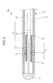
- FIG. 2 A guidewire according to a second embodiment of the present invention will be described with reference to Fig. 2 .
- a distal end of a guidewire 10a that is inserted into a body is shown at the left side, and a proximal end of the guidewire 10a that is manipulated by an operator, such as a doctor, is shown at the right side.
- Components similar to those in the above-described embodiment are denoted by the same reference numerals, and differences from the above-described embodiment will be mainly described.
- the structure of a bonding portion for bonding the inner coil body 40 differs from that in the first embodiment.
- the intermediate portion 43 of the inner coil body 40 is bonded to the outer coil body 30 by an outer bonding portion 51.
- the outer bonding portion 51 is the only bonding portion used to bond the inner coil body 40.
- the outer bonding portion 51 bonds the inner coil body 40 only to the outer coil body 30, and not to the core shaft 20. Similar to the first embodiment, the distal end 41 and the proximal end 42 of the inner coil body 40 are free ends.
- the distal end 41 and the proximal end 42 of the inner coil body 40 are free ends, as in the first embodiment. Therefore, as described above, the rigidity gradually varies in the regions around the distal end 41 and the proximal end 42 of the inner coil body 40.
- the rigidity of the guidewire 10a includes the rigidities of the "core shaft”, the “inner coil body”, and the “outer coil body”.
- the rigidity of the guidewire 10a includes the rigidities of the "core shaft”, the “inner coil body”, the “outer coil body”, and the "outer bonding portion”. Therefore, in the region around the outer bonding portion 51, the rigidity of the guidewire 10a changes only by the rigidity of the "outer bonding portion” that bonds only the inner coil body 40 and the outer coil body 30 together, and the rigidity variation is gradual.
- the distal end 41 and the proximal end 42 of the inner coil body 40 are free ends having no bonding portions.
- the outer bonding portion 51 for bonding the inner coil body 40 bonds the inner coil body 40 to only one of the core shaft 20 and the outer coil body 30 (to the outer coil body 30 in this case). Therefore, the distal portion of the guidewire is sufficiently flexible.
- plastic deformation can be prevented by suppressing stress concentration due to bending of the distal portion of the guidewire.
- FIG. 3 A guidewire according to a third embodiment of the present invention will be described with reference to Fig. 3 .
- a distal end of a guidewire 10b that is inserted into a body is shown at the left side, and a proximal end of the guidewire 10b that is manipulated by an operator, such as a doctor, is shown at the right side.
- Components similar to those in the above-described embodiments are denoted by the same reference numerals, and differences from the above-described embodiments will be mainly described.
- the structure of bonding portions for bonding the inner coil body 40 differs from those in the first and second embodiments.
- the intermediate portion 43 of the inner coil body 40 is bonded to the outer coil body 30 by an outer bonding portion 52.
- a distal inner bonding portion 53 which bonds the inner coil body 40 to the core shaft 20, is disposed between the intermediate portion 43 and the distal end 41 of the inner coil body 40.
- a proximal inner bonding portion 54 which also bonds the inner coil body 40 to the core shaft 20, is disposed between the intermediate portion 43 and the proximal end 42 of the inner coil body 40.
- the inner coil body 40 is bonded by three bonding portions, which are the outer bonding portion 52, the distal inner bonding portion 53, and the proximal inner bonding portion 54.
- the outer bonding portion 52 bonds the inner coil body 40 only to the outer coil body 30, and not to the core shaft 20.
- the distal inner bonding portion 53 bonds the inner coil body 40 only to the core shaft 20, and not to the outer coil body 30.
- the proximal inner bonding portion 54 bonds the inner coil body 40 only to the core shaft 20, and not to the outer coil body 30. Similar to the first and second embodiments, the distal end 41 and the proximal end 42 of the inner coil body 40 are free ends.
- the distal end 41 and the proximal end 42 of the inner coil body 40 are free ends, as in the first and second embodiments. Therefore, as described above, the rigidity gradually varies in the regions around the distal end 41 and the proximal end 42 of the inner coil body 40.
- the rigidity of the guidewire 10b includes the rigidities of the "core shaft”, the “inner coil body”, and the “outer coil body”.
- the rigidity of the guidewire 10b includes the rigidities of the "core shaft”, the “inner coil body”, the “outer coil body”, and the "distal inner bonding portion”.
- the rigidity of the guidewire 10b changes only by the rigidity of the "distal inner bonding portion" that bonds only the core shaft 20 and the inner coil body 40 together, and the rigidity variation is gradual.
- the rigidity of the guidewire 10b includes the rigidities of the "core shaft”, the “inner coil body”, and the “outer coil body”.
- the rigidity of the guidewire 10b includes the rigidities of the "core shaft”, the “inner coil body”, the “outer coil body”, and the "outer bonding portion”. Therefore, in the region around the outer bonding portion 52, the rigidity of the guidewire 10b changes only by the rigidity of the "outer bonding portion” that bonds only the inner coil body 40 and the outer coil body 30 together, and the rigidity variation is gradual.
- the rigidity of the guidewire 10b includes the rigidities of the "core shaft”, the “inner coil body”, and the “outer coil body”.
- the rigidity of the guidewire 10b includes the rigidities of the "core shaft”, the “inner coil body”, the “outer coil body”, and the "proximal inner bonding portion”.
- the rigidity of the guidewire 10b changes only by the rigidity of the "proximal inner bonding portion" that bonds only the core shaft 20 and the inner coil body 40 together, and the rigidity variation is gradual.
- the distal end 41 and the proximal end 42 of the inner coil body 40 are free ends having no bonding portions.
- the outer bonding portion 52, the distal inner bonding portion 53, and the proximal inner bonding portion 54 for bonding the inner coil body 40 each bond the inner coil body 40 to only one of the core shaft 20 and the outer coil body 30. Therefore, the distal portion of the guidewire is sufficiently flexible. In addition, since there is no sudden change in the rigidity of the guidewire, plastic deformation can be prevented by suppressing stress concentration due to bending of the distal portion of the guidewire.
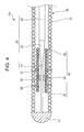
- a guidewire according to a fourth embodiment of the present invention will be described with reference to Fig. 4 .
- a distal end of a guidewire 10c that is inserted into a body is shown at the left side, and a proximal end of the guidewire 10c that is manipulated by an operator, such as a doctor, is shown at the right side.
- Components similar to those in the above-described embodiments are denoted by the same reference numerals, and differences from the above-described embodiments will be mainly described.
- the structure of bonding portions for bonding the inner coil body 40 differs from those in the first to third embodiments.
- the intermediate portion 43 of the inner coil body 40 is bonded to the core shaft 20 by an inner bonding portion 55.
- a distal outer bonding portion 56 which bonds the inner coil body 40 to the outer coil body 30, is disposed between the intermediate portion 43 and the distal end 41 of the inner coil body 40.
- a proximal outer bonding portion 57 which also bonds the inner coil body 40 to the outer coil body 30, is disposed between the intermediate portion 43 and the proximal end 42 of the inner coil body 40.
- the inner coil body 40 is bonded by three bonding portions, which are the inner bonding portion 55, the distal outer bonding portion 56, and the proximal outer bonding portion 57.
- the inner bonding portion 55 bonds the inner coil body 40 only to the core shaft 20, and not to the outer coil body 30.
- the distal outer bonding portion 56 bonds the inner coil body 40 only to the outer coil body 30, and not to the core shaft 20.
- the proximal outer bonding portion 57 bonds the inner coil body 40 only to the outer coil body 30, and not to the core shaft 20. Similar to the first to third embodiments, the distal end 41 and the proximal end 42 of the inner coil body 40 are free ends.
- the distal end 41 and the proximal end 42 of the inner coil body 40 are free ends, as in the first to third embodiments. Therefore, as described above, the rigidity gradually varies in the regions around the distal end 41 and the proximal end 42 of the inner coil body 40.
- the rigidity of the guidewire 10c includes the rigidities of the "core shaft”, the “inner coil body”, and the “outer coil body”.
- the rigidity of the guidewire 10c includes the rigidities of the "core shaft”, the “inner coil body”, the “outer coil body”, and the "distal outer bonding portion”.
- the rigidity of the guidewire 10c changes only by the rigidity of the "distal outer bonding portion" that bonds only the inner coil body 40 and the outer coil body 30 together, and the rigidity variation is gradual.
- the rigidity of the guidewire 10c includes the rigidities of the "core shaft”, the “inner coil body”, and the “outer coil body”.
- the rigidity of the guidewire 10c includes the rigidities of the "core shaft”, the “inner coil body”, the “outer coil body”, and the "inner bonding portion”. Therefore, in the region around the inner bonding portion 55, the rigidity of the guidewire 10c changes only by the rigidity of the "inner bonding portion” that bonds only the core shaft 20 and the inner coil body 40 together, and the rigidity variation is gradual.
- the rigidity of the guidewire 10c includes the rigidities of the "core shaft”, the “inner coil body”, and the “outer coil body”.
- the rigidity of the guidewire 10c includes the rigidities of the "core shaft”, the “inner coil body”, the “outer coil body”, and the "distal outer bonding portion”.
- the rigidity of the guidewire 10c changes only by the rigidity of the "proximal outer bonding portion" that bonds only the inner coil body 40 and the outer coil body 30 together, and the rigidity variation is gradual.
- the distal end 41 and the proximal end 42 of the inner coil body 40 are free ends having no bonding portions.
- the inner bonding portion 55, the distal outer bonding portion 56, and the proximal outer bonding portion 57 for bonding the inner coil body 40 each bond the inner coil body 40 to only one of the core shaft 20 and the outer coil body 30. Therefore, the distal portion of the guidewire is sufficiently flexible.
- plastic deformation can be prevented by suppressing stress concentration due to bending of the distal portion of the guidewire.
- FIG. 5 A guidewire according to a fifth embodiment of the present invention will be described with reference to Fig. 5 .
- a distal end of a guidewire 10d that is inserted into a body is shown at the left side, and a proximal end of the guidewire 10d that is manipulated by an operator, such as a doctor, is shown at the right side.
- Components similar to those in the above-described embodiments are denoted by the same reference numerals, and differences from the above-described embodiments will be mainly described.
- the guidewire 10d according to the fifth embodiment includes an inner coil body 60 having a structure that differs from that in the first to fourth embodiments.
- the structure of bonding portions for bonding the inner coil body 60 is basically similar to that in the third embodiment. However, the positional relationship between the bonding portions and the core shaft differ from those in the first to fourth embodiments.
- the inner coil body 60 includes a distal coil portion 61, an intermediate coil portion 62, and a proximal coil portion 63.
- the coil portions 61, 62, and 63 of the inner coil body 60 are formed as an integral coil in the present invention. However, the coil portions 61, 62, and 63 may instead be formed separately.
- the distal end of the distal coil portion 61 is a free end having no bonding portions.
- the proximal end of the distal coil portion 61 is bonded to the small-diameter portion 21 of the core shaft 20 by a distal inner bonding portion 65.
- a central portion of the intermediate coil portion 62 is bonded to the outer coil body 30 by an outer bonding portion 66.
- the proximal end of the intermediate coil portion 62 is bonded to the tapered portion 22 of the core shaft 20 by a proximal inner bonding portion 67.
- the proximal end of the proximal coil portion 63 is a free end having no bonding portions.
- the wire diameter and the outer coil diameter of the distal coil portion 61 decrease toward the distal end.
- the intermediate coil portion 62 has a constant wire diameter and a constant outer coil diameter.
- the wire diameter and the outer coil diameter of the proximal coil portion 63 decrease toward the proximal end.
- the distal coil portion 61 and the proximal coil portion 63 are processed by, for example, electropolishing.
- the distal coil portion 61 and the proximal coil portion 63 of the present embodiment are formed such that not only the wire diameter but also the outer coil diameter decreases.
- the distal coil portion 61 and the proximal coil portion 63 may instead be formed such that only the wire diameter decreases while the outer coil diameter is constant.
- the distal coil portion 61 and the proximal coil portion 63 may be formed such that only the outer coil diameter decreases while the wire diameter is constant. In this case, the pitch is preferably increased to ensure sufficient flexibility.
- the outer bonding portion 66 is disposed at a position corresponding to the boundary between the small-diameter portion 21 and the tapered portion 22 of the core shaft 20. Accordingly, the rigidity at the proximal side of the outer bonding portion 66 is higher than that at the distal side of the outer bonding portion 66 by an amount corresponding to an increase in diameter of the tapered portion 22.
- all of the bonding portions 65 to 67 are disposed at positions where the rigidity changes.
- the rigidity increases in the order of the region on the distal side of the distal inner bonding portion 65, the region between the distal inner bonding portion 65 and the outer bonding portion 66, the region between the outer bonding portion 66 and the proximal inner bonding portion 67, and the region on the proximal side of the proximal inner bonding portion 67.
- the distal end of the distal coil portion 61 and the proximal end of the proximal coil portion 63 are free ends having no bonding portions.
- the distal inner bonding portion 65, the outer bonding portion 66, and the proximal inner bonding portion 67 for bonding the inner coil body 60 each bond the inner coil body 60 to only one of the core shaft 20 and the outer coil body 30.
- the outer coil diameter of the distal coil portion 61 decreases toward the distal end
- the outer coil diameter of the proximal coil portion 63 decreases toward the proximal end. Therefore, the rigidity of the guidewire 10d varies more gradually and stress concentration due to bending can be further suppressed.
- the wire diameter of the distal coil portion 61 decreases toward the distal end
- the wire diameter of the proximal coil portion 63 decreases toward the proximal end. Therefore, the rigidity of the guidewire 10d varies more gradually and stress concentration due to bending can be further suppressed.
- the distal coil portion 61 covers the small-diameter portion 21 of the core shaft 20, the effect of making the rigidity variation gradual is higher than that at the proximal coil portion 63 that covers the tapered portion 22, which has a diameter larger than that of the small-diameter portion 21. Therefore, the distal coil portion 61 is preferably longer than the proximal coil portion 63, and the wire diameter at the distal end of the distal coil portion 61 is preferably smaller than that at the proximal end of the proximal coil portion 63.
- a guidewire according to a sixth embodiment of the present invention will be described with reference to Fig. 6 .
- a distal end of a guidewire 10e that is inserted into a body is shown at the left side, and a proximal end of the guidewire 10e that is manipulated by an operator, such as a doctor, is shown at the right side.
- Components similar to those in the above-described embodiments are denoted by the same reference numerals, and differences from the above-described embodiments will be mainly described.
- the guidewire 10e according to the sixth embodiment includes an inner coil body 70 having a structure that differs from that in the first to fifth embodiments.
- the structure of bonding portions for bonding the inner coil body 70 is similar to that in the fifth embodiment.
- the inner coil body 70 includes a distal coil portion 71, an intermediate coil portion 72, and a proximal coil portion 73.
- the coil portions 71, 72, and 73 of the inner coil body 70 are formed as an integral coil in the present invention. However, the coil portions 71, 72, and 73 may instead be formed separately.
- the distal end of the distal coil portion 71 is a free end having no bonding portions.
- the proximal end of the distal coil portion 71 is bonded to the small-diameter portion 21 of the core shaft 20 by a distal inner bonding portion 75.
- a central portion of the intermediate coil portion 72 is bonded to the outer coil body 30 by an outer bonding portion 76.
- the proximal end of the intermediate coil portion 72 is bonded to the tapered portion 22 of the core shaft 20 by a proximal inner bonding portion 77.
- the proximal end of the proximal coil portion 73 is a free end having no bonding portions.
- the outer peripheral surface of the distal coil portion 71 is ground and tapered so that the diameter of the distal coil portion 71 decreases toward the distal end.
- the intermediate coil portion 72 has a constant wire diameter and a constant outer coil diameter.
- the outer peripheral surface of the proximal coil portion 73 is ground and tapered so that the diameter of the proximal coil portion 73 decreases toward the proximal end.
- the distal coil portion 71 and the proximal coil portion 73 are processed by, for example, centerless grinding.
- the pitch is increased in the distal coil portion 71 and the proximal coil portion 73. By increasing the pitch, the flexibility of the inner coil body 70 can be further increased at the distal end and the proximal end. In particular, the pitch is preferably gradually increased toward the distal end and the proximal end, so that the rigidity changes gradually.
- the distal end of the distal coil portion 71 and the proximal end of the proximal coil portion 73 are free ends having no bonding portions.
- the distal inner bonding portion 75, the outer bonding portion 76, and the proximal inner bonding portion 77 for bonding the inner coil body 70 each bond the inner coil body 70 to only one of the core shaft 20 and the outer coil body 30.
- the outer coil diameter of the distal coil portion 71 decreases toward the distal end
- the outer coil diameter of the proximal coil portion 73 decreases toward the proximal end. Therefore, the rigidity of the guidewire 10e varies more gradually and stress concentration due to bending can be further suppressed.
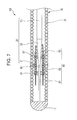
- a guidewire according to a seventh embodiment of the present invention will be described with reference to Fig. 7 .
- a distal end of a guidewire 10f that is inserted into a body is shown at the left side, and a proximal end of the guidewire 10f that is manipulated by an operator, such as a doctor, is shown at the right side.
- Components similar to those in the above-described embodiments are denoted by the same reference numerals, and differences from the above-described embodiments will be mainly described.
- the guidewire 10f according to the seventh embodiment includes an inner coil body 80 having a structure that differs from that in the first to sixth embodiments.
- the structure of bonding portions for bonding the inner coil body 80 is similar to that in the fifth and sixth embodiments.
- the inner coil body 80 includes a distal coil portion 81, an intermediate coil portion 82, and a proximal coil portion 83.
- the coil portions 81, 82, and 83 of the inner coil body 80 according to the present embodiment are formed separately.
- the distal end of the distal coil portion 81 is a free end having no bonding portions.
- the proximal end of the distal coil portion 81 is bonded to the distal end of the intermediate coil portion 82 and the small-diameter portion 21 of the core shaft 20 by a distal inner bonding portion 85.
- a central portion of the intermediate coil portion 82 is bonded to the outer coil body 30 by an outer bonding portion 86.
- the proximal end of the intermediate coil portion 82 is bonded to the distal end of the proximal coil portion 83 and the tapered portion 22 of the core shaft 20 by a proximal inner bonding portion 87.
- the proximal end of the proximal coil portion 83 is a free end having no bonding portions.
- the distal coil portion 81 has a constant wire diameter that is smaller than that of the intermediate coil portion 82.
- the intermediate coil portion 82 has a constant wire diameter and a constant outer coil diameter.
- the outer peripheral surface of the proximal coil portion 83 is ground and tapered so that the diameter of the proximal coil portion 83 decreases toward the proximal end.
- the inner coil body 80 includes the distal coil portion 81 which covers a flexible portion (small-diameter portion 21) of the core shaft 20 at the distal side, and the wire diameter of the distal coil portion 81 is smaller than that of the intermediate coil portion 82. Therefore, an effect of ensuring sufficient flexibility of the flexible portion (small-diameter portion 21) of the core shaft 20 while setting the rigidity of the distal portion of the guidewire 10f such that the rigidity changes stepwise can be provided in addition to the effects of the above-described embodiments.
- the distal coil portion 81 of the inner coil body 80 is formed such that the wire diameter decreases toward the distal end, the rigidity of the distal portion of the guidewire 10f changes gradually.
- any bonding portion for bonding the inner coil according to the invention bonds the inner coil body to only one of the core shaft and the outer coil body.
- the bonding portions for bonding the inner coil body are not limited to those described in the first to seventh embodiments.
- the bonding portions may be arranged in the longitudinal direction of a guidewire and used in combination, or be applied to a coil structure including three or more coil bodies.
- bonding portions for bonding each coil body are each configured to bond the coil body to only one of another coil body and a core shaft.
- each inner coil is formed so as to have free ends at both ends thereof.
- an outer coil diameter of the inner coil body at the free end at one or both of the distal end and proximal end may decrease toward the distal end and/or proximal end, respectively.
- a wire diameter of the inner coil body at the free end at one or both of the distal end and proximal end may decrease toward the distal end and/or proximal end, respectively.
- the inner coil bodies 40, 60, 70, and 80 partially cover the small-diameter portion 21 and the tapered portion 22 of the core shaft 20 in the first to seventh embodiments, the inner coil bodies 40, 60, 70, and 80 may instead cover only the tapered portion 22.
- each of the guidewires 10 and 10a to 10f according to the first to seventh embodiments has a linear shape
- the distal portion may instead include a curved portion.
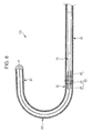
- Figs. 8 and 9 respectively show a first modification and a second modification of the guidewire 10f according to the seventh embodiment in which the distal portion has a curved portion.
- a guidewire 10g according to the first modification illustrated in Fig. 8 includes a first linear portion 91 at the distal side, a second linear portion 92 at the proximal side, and a curved portion 93 that connects the first linear portion 91 and the second linear portion 92 to each other.
- the inner coil body 80 is disposed in a distal portion of the second linear portion 92.
- the first linear portion 91 is bent from the second linear portion 92 at the curved portion 93, so that the distal ends of the first linear portion 91 and the second linear portion 92 point in opposite directions.
- the guidewire 10g according to the first modification includes the first linear portion 91 at the distal side, the second linear portion 92 at the proximal side, and the curved portion 93 that connects the first linear portion 91 and the second linear portion 92 to each other, and the inner coil body 80 is disposed in the second linear portion 92. Therefore, the inner coil body 80 serves as a flexible fulcrum at a position where the distal portion of the guidewire is bent, and blood vessel selectivity can be increased.
- a guidewire 10h according to the second modification illustrated in Fig. 9 includes a first linear portion 94 at the distal side, a second linear portion 95 at the proximal side, and three curved portions 96, 97, and 98 that connect the first linear portion 94 and the second linear portion 95 to each other.
- the inner coil body 80 is disposed in a distal portion of the second linear portion 95.
- the first linear portion 94 and the second linear portion 95 are parallel to each other, and the distal ends thereof point in the same direction.
- the guidewire 10h according to the second modification provides not only the effect of the above-described first modification but also an effect of increasing pushing performance in a blood vessel since the first linear portion 94 and the second linear portion 95 are parallel to each other and the distal ends thereof point in the same direction.
Landscapes
- Health & Medical Sciences (AREA)
- Life Sciences & Earth Sciences (AREA)
- General Health & Medical Sciences (AREA)
- Veterinary Medicine (AREA)
- Engineering & Computer Science (AREA)
- Biomedical Technology (AREA)
- Heart & Thoracic Surgery (AREA)
- Public Health (AREA)
- Animal Behavior & Ethology (AREA)
- Surgery (AREA)
- Anesthesiology (AREA)
- Hematology (AREA)
- Pulmonology (AREA)
- Biophysics (AREA)
- Gastroenterology & Hepatology (AREA)
- Pathology (AREA)
- Nuclear Medicine, Radiotherapy & Molecular Imaging (AREA)
- Medical Informatics (AREA)
- Molecular Biology (AREA)
- Media Introduction/Drainage Providing Device (AREA)
- Connector Housings Or Holding Contact Members (AREA)
Abstract
Description
- The present invention relates to a medical guidewire.
- Various guidewires have been proposed which guide a catheter or the like that is inserted into a tubular organ, such as a blood vessel, an alimentary canal, or a ureter, or a body tissue for the purpose of treatment or diagnosis.
- For example, Japanese Unexamined Patent Application Publication No.
8-317989 Fig. 1 ). - However, it is difficult to make the distal portion of the medical guidewire according to Japanese Unexamined Patent Application Publication No.
8-317989 - Accordingly, United States Patent No.
5,345,945 discloses a guidewire in which two coil bodies including an inner coil body and an outer coil body are provided at a distal portion of the guidewire and the inner coil body has free ends having no bonding portions so that the distal portion is sufficiently flexible (see, for example,Fig. 3 ). - However, in the guidewire according to United States Patent No.
5,345,945 , a bonding section for bonding the inner coil body bonds three components together, the three components being a core shaft, the inner coil body, and the outer coil body. Accordingly, the rigidity of the guidewire at the bonding section includes not only the rigidities of the core shaft, the inner coil body, and the outer coil body but also the rigidity of an inner bonding portion that bonds the inner coil body to the core shaft and the rigidity of an outer bonding portion that bonds the inner coil body to the outer coil body. In contrast, the rigidity of the guidewire at each of the free ends on the distal and proximal sides of the bonding section includes only the rigidities of the core shaft, the inner coil body, and the outer coil body. Therefore, the rigidity of the guidewire suddenly changes in the region around the bonding section, and stress concentration occurs when the guidewire is bent. As a result, plastic deformation easily occurs. - The present invention has been made in view of the above-described circumstances, and an object of the present invention is to provide a guidewire which includes a sufficiently flexible distal portion and with which plastic deformation can be prevented by suppressing stress concentration due to bending of the guidewire.
- To achieve the above-described object, a guidewire according to an aspect of the present invention has the following features.
- That is, according to an aspect of the present invention, a guidewire includes a core shaft, an outer coil body that covers an outer periphery of the core shaft, and an inner coil body that covers a distal portion of the core shaft in the outer coil body. A distal end and a proximal end of the inner coil body are free ends having no bonding portions. A bonding portion for bonding the inner coil body bonds the inner coil body to only one of the core shaft and the outer coil body.
- In the guidewire according to the aspect, the distal and proximal ends of the inner coil body are free ends having no bonding portions, and the bonding portion for bonding the inner coil body bonds the inner coil body to only one of the core shaft and the outer coil body. Therefore, the distal portion of the guidewire is sufficiently flexible. In addition, since there is no sudden change in the rigidity of the guidewire, plastic deformation can be prevented by suppressing stress concentration due to bending of the distal portion of the guidewire.
-
-
Fig. 1 illustrates the overall structure of a guidewire according to a first embodiment. -
Fig. 2 is an enlarged view of a part of a guidewire according to a second embodiment. -
Fig. 3 is an enlarged view of a part of a guidewire according to a third embodiment. -
Fig. 4 is an enlarged view of a part of a guidewire according to a fourth embodiment. -
Fig. 5 is an enlarged view of a part of a guidewire according to a fifth embodiment. -
Fig. 6 is an enlarged view of a part of a guidewire according to a sixth embodiment. -
Fig. 7 is an enlarged view of a part of a guidewire according to a seventh embodiment. -
Fig. 8 is an enlarged view of a part of a guidewire according to a first modification. -
Fig. 9 is an enlarged view of a part of a guidewire according to a second modification. - A guidewire according to a first embodiment of the present invention will be described with reference to
Fig. 1 . Referring toFig. 1 , a distal end of aguidewire 10 that is inserted into a body is shown at the left side, and a proximal end of theguidewire 10 that is manipulated by an operator, such as a doctor, is shown at the right side. The drawings are schematic diagrams of guidewires, and dimensional ratios of components shown in the drawings differ from the actual ratios. - As illustrated in
Fig. 1 , theguidewire 10 includes acore shaft 20, anouter coil body 30 that covers the outer periphery of thecore shaft 20, and aninner coil body 40 that covers a distal portion of thecore shaft 20 in theouter coil body 30. A distal portion of theguidewire 10 has a straight shape. - The
core shaft 20 includes a small-diameter portion 21, atapered portion 22, and a large-diameter portion 23 arranged in that order from the distal end thereof to the proximal end thereof. The small-diameter portion 21 is at the distal end of thecore shaft 20, and is a most flexible portion of thecore shaft 20. The small-diameter portion 21 is formed in a flat plate shape by press working. Thetapered portion 22 has a circular cross section and is tapered so that the diameter thereof decreases toward the distal side. The large-diameter portion 23 has a columnar shape with a constant diameter. The arrangement and dimensions of the small-diameter portion 21, thetapered portion 22, and the large-diameter portion 23 may be changed as appropriate in order to, for example, obtain a desired rigidity. For example, the small-diameter portion 21 may have a columnar shape. The number of tapered portions and the taper angle of each tapered portion may also be set as appropriate. The material of thecore shaft 20 is not particularly limited. In the present embodiment, a stainless steel (SUS304) is used. Alternatively, a superelastic alloy, such as Ni-Ti alloy, may be used as the material. - The
outer coil body 30 includes adistal coil portion 31 and aproximal coil portion 32. The distal end of thedistal coil portion 31 is bonded to the distal end of thecore shaft 20 by adistal tip 11. The proximal end of thedistal coil portion 31 is bonded to the distal end of theproximal coil portion 32 and thecore shaft 20 by an intermediate bonding portion (not shown). The proximal end of theproximal coil portion 32 is bonded to the proximal end of thecore shaft 20 by a proximal-end bonding portion 12. In the present embodiment, thedistal coil portion 31 is a single-wire coil. Thedistal coil portion 31 has a constant outer coil diameter and a constant wire diameter over the entire length thereof. Theproximal coil portion 32 is a multiple-wire coil (stranded-wire coil formed of multiple wires), and thereby has a high torque transmission performance. - The
inner coil body 40 partially covers the small-diameter portion 21 and thetapered portion 22 of thecore shaft 20. In other words, adistal end 41 of theinner coil body 40 is positioned at the small-diameter portion 21 of thecore shaft 20, and aproximal end 42 of theinner coil body 40 is positioned at thetapered portion 22 of thecore shaft 20. Anintermediate portion 43 of theinner coil body 40 extends so as to partially cover the small-diameter portion 21 and thetapered portion 22 of thecore shaft 20. Thedistal end 41 and theproximal end 42 of theinner coil body 40 are free ends having no bonding portions. Theintermediate portion 43 of theinner coil body 40 is bonded to the small-diameter portion 21 of thecore shaft 20 by aninner bonding portion 13. Thus, in the present embodiment, theinner bonding portion 13 is the only bonding portion used to bond theinner coil body 40. Theinner bonding portion 13 bonds theinner coil body 40 only to thecore shaft 20, and not to theouter coil body 30. Theinner coil body 40 according to the present embodiment has a constant outer coil diameter and a constant wire diameter over the entire length thereof. - The material of the
outer coil body 30 and theinner coil body 40 is not particularly limited. In the present embodiment, a stainless steel is used. Alternatively, a superelastic alloy, such as tungsten or Ni-Ti alloy, may be used. Alternatively, wires made of different materials may be used in combination. The material of thedistal tip 11 and thebonding portions - In the
guidewire 10 having the above-described structure, thedistal end 41 and theproximal end 42 of theinner coil body 40 are free ends having no bonding portions. Theinner bonding portion 13 for bonding theinner coil body 40 bonds theinner coil body 40 only to thecore shaft 20. The rigidity variation in the distal portion of theguidewire 10 according to the present embodiment will now be discussed. - First, the rigidity variation in a region around the
distal end 41 of theinner coil body 40 will be described. In a region on the distal side of thedistal end 41 of theinner coil body 40, the rigidity of theguidewire 10 includes the rigidities of the "core shaft" and the "outer coil body". In a region on the proximal side of thedistal end 41 of theinner coil body 40, the rigidity of theguidewire 10 includes the rigidities of the "core shaft", the "inner coil body", and the "outer coil body". Therefore, in the region around thedistal end 41 of theinner coil body 40, the rigidity of the guidewire 10 changes only by the rigidity of the "inner coil body", and the rigidity variation is gradual. - Next, the rigidity variation in a region around the
inner bonding portion 13 will be described. In regions on the distal side and the proximal side of theinner bonding portion 13, the rigidity of theguidewire 10 includes the rigidities of the "core shaft", the "inner coil body", and the "outer coil body". In the region where theinner bonding portion 13 is disposed, the rigidity of theguidewire 10 includes the rigidities of the "core shaft", the "inner coil body", the "outer coil body", and the "inner bonding portion". Therefore, in the region around theinner bonding portion 13, the rigidity of the guidewire 10 changes only by the rigidity of the "inner bonding portion" that bonds only thecore shaft 20 and theinner coil body 40 together, and the rigidity variation is gradual. - Next, the rigidity variation in a region around the
proximal end 42 of theinner coil body 40 will be described. First, in a region on the distal side of theproximal end 42 of theinner coil body 40, the rigidity of theguidewire 10 includes the rigidities of the "core shaft", the "inner coil body", and the "outer coil body". In a region on the proximal side of theproximal end 42 of theinner coil body 40, the rigidity of theguidewire 10 includes the rigidities of the "core shaft" and the "outer coil body". Therefore, in the region around theproximal end 42 of theinner coil body 40, the rigidity of the guidewire 10 changes only by the rigidity of the "inner coil body", and the rigidity variation is gradual. - As described above, in the
guidewire 10 according to the present embodiment, thedistal end 41 and theproximal end 42 of theinner coil body 40 are free ends having no bonding portions. Theinner bonding portion 13 for bonding theinner coil body 40 bonds theinner coil body 40 to only one of thecore shaft 20 and the outer coil body 30 (to thecore shaft 20 in this case). Therefore, the distal portion of the guidewire is sufficiently flexible. In addition, since there is no sudden change in the rigidity of the guidewire, plastic deformation can be prevented by suppressing stress concentration due to bending of the distal portion of the guidewire. - A guidewire according to a second embodiment of the present invention will be described with reference to
Fig. 2 . Referring toFig. 2 , a distal end of aguidewire 10a that is inserted into a body is shown at the left side, and a proximal end of theguidewire 10a that is manipulated by an operator, such as a doctor, is shown at the right side. Components similar to those in the above-described embodiment are denoted by the same reference numerals, and differences from the above-described embodiment will be mainly described. - In the
guidewire 10a according to the second embodiment, the structure of a bonding portion for bonding theinner coil body 40 differs from that in the first embodiment. - As illustrated in
Fig. 2 , theintermediate portion 43 of theinner coil body 40 is bonded to theouter coil body 30 by anouter bonding portion 51. Thus, in the second embodiment, theouter bonding portion 51 is the only bonding portion used to bond theinner coil body 40. Theouter bonding portion 51 bonds theinner coil body 40 only to theouter coil body 30, and not to thecore shaft 20. Similar to the first embodiment, thedistal end 41 and theproximal end 42 of theinner coil body 40 are free ends. - The rigidity variation in the distal portion of the
guidewire 10a according to the second embodiment will now be discussed. - In the present embodiment, the
distal end 41 and theproximal end 42 of theinner coil body 40 are free ends, as in the first embodiment. Therefore, as described above, the rigidity gradually varies in the regions around thedistal end 41 and theproximal end 42 of theinner coil body 40. - Next, the rigidity variation in a region around the
outer bonding portion 51 will be described. In regions on the distal side and the proximal side of theouter bonding portion 51, the rigidity of theguidewire 10a includes the rigidities of the "core shaft", the "inner coil body", and the "outer coil body". In the region where theouter bonding portion 51 is disposed, the rigidity of theguidewire 10a includes the rigidities of the "core shaft", the "inner coil body", the "outer coil body", and the "outer bonding portion". Therefore, in the region around theouter bonding portion 51, the rigidity of theguidewire 10a changes only by the rigidity of the "outer bonding portion" that bonds only theinner coil body 40 and theouter coil body 30 together, and the rigidity variation is gradual. - As described above, in the
guidewire 10a according to the second embodiment, thedistal end 41 and theproximal end 42 of theinner coil body 40 are free ends having no bonding portions. Theouter bonding portion 51 for bonding theinner coil body 40 bonds theinner coil body 40 to only one of thecore shaft 20 and the outer coil body 30 (to theouter coil body 30 in this case). Therefore, the distal portion of the guidewire is sufficiently flexible. In addition, since there is no sudden change in the rigidity of the guidewire, plastic deformation can be prevented by suppressing stress concentration due to bending of the distal portion of the guidewire. - A guidewire according to a third embodiment of the present invention will be described with reference to
Fig. 3 . Referring toFig. 3 , a distal end of aguidewire 10b that is inserted into a body is shown at the left side, and a proximal end of theguidewire 10b that is manipulated by an operator, such as a doctor, is shown at the right side. Components similar to those in the above-described embodiments are denoted by the same reference numerals, and differences from the above-described embodiments will be mainly described. - In the
guidewire 10b according to the third embodiment, the structure of bonding portions for bonding theinner coil body 40 differs from those in the first and second embodiments. - As illustrated in
Fig. 3 , theintermediate portion 43 of theinner coil body 40 is bonded to theouter coil body 30 by anouter bonding portion 52. A distalinner bonding portion 53, which bonds theinner coil body 40 to thecore shaft 20, is disposed between theintermediate portion 43 and thedistal end 41 of theinner coil body 40. A proximalinner bonding portion 54, which also bonds theinner coil body 40 to thecore shaft 20, is disposed between theintermediate portion 43 and theproximal end 42 of theinner coil body 40. Thus, in the third embodiment, theinner coil body 40 is bonded by three bonding portions, which are theouter bonding portion 52, the distalinner bonding portion 53, and the proximalinner bonding portion 54. Theouter bonding portion 52 bonds theinner coil body 40 only to theouter coil body 30, and not to thecore shaft 20. The distalinner bonding portion 53 bonds theinner coil body 40 only to thecore shaft 20, and not to theouter coil body 30. The proximalinner bonding portion 54 bonds theinner coil body 40 only to thecore shaft 20, and not to theouter coil body 30. Similar to the first and second embodiments, thedistal end 41 and theproximal end 42 of theinner coil body 40 are free ends. - The rigidity variation in the distal portion of the
guidewire 10b according to the third embodiment will now be discussed. - In the present embodiment, the
distal end 41 and theproximal end 42 of theinner coil body 40 are free ends, as in the first and second embodiments. Therefore, as described above, the rigidity gradually varies in the regions around thedistal end 41 and theproximal end 42 of theinner coil body 40. - Next, the rigidity variation in a region around the distal
inner bonding portion 53 will be described. In regions on the distal side and the proximal side of the distalinner bonding portion 53, the rigidity of theguidewire 10b includes the rigidities of the "core shaft", the "inner coil body", and the "outer coil body". In the region where the distalinner bonding portion 53 is disposed, the rigidity of theguidewire 10b includes the rigidities of the "core shaft", the "inner coil body", the "outer coil body", and the "distal inner bonding portion". Therefore, in the region around the distalinner bonding portion 53, the rigidity of the guidewire 10b changes only by the rigidity of the "distal inner bonding portion" that bonds only thecore shaft 20 and theinner coil body 40 together, and the rigidity variation is gradual. - Next, the rigidity variation in a region around the
outer bonding portion 52 will be described. In regions on the distal side and the proximal side of theouter bonding portion 52, the rigidity of theguidewire 10b includes the rigidities of the "core shaft", the "inner coil body", and the "outer coil body". In the region where theouter bonding portion 52 is disposed, the rigidity of theguidewire 10b includes the rigidities of the "core shaft", the "inner coil body", the "outer coil body", and the "outer bonding portion". Therefore, in the region around theouter bonding portion 52, the rigidity of the guidewire 10b changes only by the rigidity of the "outer bonding portion" that bonds only theinner coil body 40 and theouter coil body 30 together, and the rigidity variation is gradual. - Next, the rigidity variation in a region around the proximal
inner bonding portion 54 will be described. In regions on the distal side and the proximal side of the proximalinner bonding portion 54, the rigidity of theguidewire 10b includes the rigidities of the "core shaft", the "inner coil body", and the "outer coil body". In the region where the proximalinner bonding portion 54 is disposed, the rigidity of theguidewire 10b includes the rigidities of the "core shaft", the "inner coil body", the "outer coil body", and the "proximal inner bonding portion". Therefore, in the region around the proximalinner bonding portion 54, the rigidity of the guidewire 10b changes only by the rigidity of the "proximal inner bonding portion" that bonds only thecore shaft 20 and theinner coil body 40 together, and the rigidity variation is gradual. - As described above, in the
guidewire 10b according to the third embodiment, thedistal end 41 and theproximal end 42 of theinner coil body 40 are free ends having no bonding portions. Theouter bonding portion 52, the distalinner bonding portion 53, and the proximalinner bonding portion 54 for bonding theinner coil body 40 each bond theinner coil body 40 to only one of thecore shaft 20 and theouter coil body 30. Therefore, the distal portion of the guidewire is sufficiently flexible. In addition, since there is no sudden change in the rigidity of the guidewire, plastic deformation can be prevented by suppressing stress concentration due to bending of the distal portion of the guidewire. - A guidewire according to a fourth embodiment of the present invention will be described with reference to
Fig. 4 . Referring toFig. 4 , a distal end of aguidewire 10c that is inserted into a body is shown at the left side, and a proximal end of theguidewire 10c that is manipulated by an operator, such as a doctor, is shown at the right side. Components similar to those in the above-described embodiments are denoted by the same reference numerals, and differences from the above-described embodiments will be mainly described. - In the
guidewire 10c according to the fourth embodiment, the structure of bonding portions for bonding theinner coil body 40 differs from those in the first to third embodiments. - As illustrated in
Fig. 4 , theintermediate portion 43 of theinner coil body 40 is bonded to thecore shaft 20 by aninner bonding portion 55. A distalouter bonding portion 56, which bonds theinner coil body 40 to theouter coil body 30, is disposed between theintermediate portion 43 and thedistal end 41 of theinner coil body 40. A proximalouter bonding portion 57, which also bonds theinner coil body 40 to theouter coil body 30, is disposed between theintermediate portion 43 and theproximal end 42 of theinner coil body 40. Thus, in the fourth embodiment, theinner coil body 40 is bonded by three bonding portions, which are theinner bonding portion 55, the distalouter bonding portion 56, and the proximalouter bonding portion 57. Theinner bonding portion 55 bonds theinner coil body 40 only to thecore shaft 20, and not to theouter coil body 30. The distalouter bonding portion 56 bonds theinner coil body 40 only to theouter coil body 30, and not to thecore shaft 20. The proximalouter bonding portion 57 bonds theinner coil body 40 only to theouter coil body 30, and not to thecore shaft 20. Similar to the first to third embodiments, thedistal end 41 and theproximal end 42 of theinner coil body 40 are free ends. - The rigidity variation in the distal portion of the
guidewire 10c according to the fourth embodiment will now be discussed. - In the present embodiment, the
distal end 41 and theproximal end 42 of theinner coil body 40 are free ends, as in the first to third embodiments. Therefore, as described above, the rigidity gradually varies in the regions around thedistal end 41 and theproximal end 42 of theinner coil body 40. - Next, the rigidity variation in a region around the distal
outer bonding portion 56 will be described. In regions on the distal side and the proximal side of the distalouter bonding portion 56, the rigidity of theguidewire 10c includes the rigidities of the "core shaft", the "inner coil body", and the "outer coil body". In the region where the distalouter bonding portion 56 is disposed, the rigidity of theguidewire 10c includes the rigidities of the "core shaft", the "inner coil body", the "outer coil body", and the "distal outer bonding portion". Therefore, in the region around the distalouter bonding portion 56, the rigidity of the guidewire 10c changes only by the rigidity of the "distal outer bonding portion" that bonds only theinner coil body 40 and theouter coil body 30 together, and the rigidity variation is gradual. - Next, the rigidity variation in a region around the
inner bonding portion 55 will be described. In regions on the distal side and the proximal side of theinner bonding portion 55, the rigidity of theguidewire 10c includes the rigidities of the "core shaft", the "inner coil body", and the "outer coil body". In the region where theinner bonding portion 55 is disposed, the rigidity of theguidewire 10c includes the rigidities of the "core shaft", the "inner coil body", the "outer coil body", and the "inner bonding portion". Therefore, in the region around theinner bonding portion 55, the rigidity of the guidewire 10c changes only by the rigidity of the "inner bonding portion" that bonds only thecore shaft 20 and theinner coil body 40 together, and the rigidity variation is gradual. - Next, the rigidity variation in a region around the proximal
outer bonding portion 57 will be described. In regions on the distal side and the proximal side of the proximalouter bonding portion 57, the rigidity of theguidewire 10c includes the rigidities of the "core shaft", the "inner coil body", and the "outer coil body". In the region where the proximalouter bonding portion 57 is disposed, the rigidity of theguidewire 10c includes the rigidities of the "core shaft", the "inner coil body", the "outer coil body", and the "distal outer bonding portion". Therefore, in the region around the proximalouter bonding portion 57, the rigidity of the guidewire 10c changes only by the rigidity of the "proximal outer bonding portion" that bonds only theinner coil body 40 and theouter coil body 30 together, and the rigidity variation is gradual. - As described above, in the
guidewire 10c according to the fourth embodiment, thedistal end 41 and theproximal end 42 of theinner coil body 40 are free ends having no bonding portions. Theinner bonding portion 55, the distalouter bonding portion 56, and the proximalouter bonding portion 57 for bonding theinner coil body 40 each bond theinner coil body 40 to only one of thecore shaft 20 and theouter coil body 30. Therefore, the distal portion of the guidewire is sufficiently flexible. In addition, since there is no sudden change in the rigidity of the guidewire, plastic deformation can be prevented by suppressing stress concentration due to bending of the distal portion of the guidewire. - A guidewire according to a fifth embodiment of the present invention will be described with reference to
Fig. 5 . Referring toFig. 5 , a distal end of aguidewire 10d that is inserted into a body is shown at the left side, and a proximal end of theguidewire 10d that is manipulated by an operator, such as a doctor, is shown at the right side. Components similar to those in the above-described embodiments are denoted by the same reference numerals, and differences from the above-described embodiments will be mainly described. - The
guidewire 10d according to the fifth embodiment includes aninner coil body 60 having a structure that differs from that in the first to fourth embodiments. The structure of bonding portions for bonding theinner coil body 60 is basically similar to that in the third embodiment. However, the positional relationship between the bonding portions and the core shaft differ from those in the first to fourth embodiments. - As illustrated in
Fig. 5 , theinner coil body 60 includes adistal coil portion 61, anintermediate coil portion 62, and aproximal coil portion 63. Thecoil portions inner coil body 60 are formed as an integral coil in the present invention. However, thecoil portions distal coil portion 61 is a free end having no bonding portions. The proximal end of thedistal coil portion 61 is bonded to the small-diameter portion 21 of thecore shaft 20 by a distalinner bonding portion 65. A central portion of theintermediate coil portion 62 is bonded to theouter coil body 30 by anouter bonding portion 66. The proximal end of theintermediate coil portion 62 is bonded to the taperedportion 22 of thecore shaft 20 by a proximalinner bonding portion 67. The proximal end of theproximal coil portion 63 is a free end having no bonding portions. - In the
inner coil body 60 of the present embodiment, the wire diameter and the outer coil diameter of thedistal coil portion 61 decrease toward the distal end. Theintermediate coil portion 62 has a constant wire diameter and a constant outer coil diameter. The wire diameter and the outer coil diameter of theproximal coil portion 63 decrease toward the proximal end. Thedistal coil portion 61 and theproximal coil portion 63 are processed by, for example, electropolishing. Thedistal coil portion 61 and theproximal coil portion 63 of the present embodiment are formed such that not only the wire diameter but also the outer coil diameter decreases. However, thedistal coil portion 61 and theproximal coil portion 63 may instead be formed such that only the wire diameter decreases while the outer coil diameter is constant. Alternatively, thedistal coil portion 61 and theproximal coil portion 63 may be formed such that only the outer coil diameter decreases while the wire diameter is constant. In this case, the pitch is preferably increased to ensure sufficient flexibility. - In the present embodiment, the
outer bonding portion 66 is disposed at a position corresponding to the boundary between the small-diameter portion 21 and the taperedportion 22 of thecore shaft 20. Accordingly, the rigidity at the proximal side of theouter bonding portion 66 is higher than that at the distal side of theouter bonding portion 66 by an amount corresponding to an increase in diameter of the taperedportion 22. In theguidewire 10d according to the present embodiment, all of thebonding portions 65 to 67 are disposed at positions where the rigidity changes. The rigidity increases in the order of the region on the distal side of the distalinner bonding portion 65, the region between the distalinner bonding portion 65 and theouter bonding portion 66, the region between theouter bonding portion 66 and the proximalinner bonding portion 67, and the region on the proximal side of the proximalinner bonding portion 67. - In the
guidewire 10d according to the fifth embodiment having the above-described structure, the distal end of thedistal coil portion 61 and the proximal end of theproximal coil portion 63 are free ends having no bonding portions. The distalinner bonding portion 65, theouter bonding portion 66, and the proximalinner bonding portion 67 for bonding theinner coil body 60 each bond theinner coil body 60 to only one of thecore shaft 20 and theouter coil body 30. In theinner coil body 60, the outer coil diameter of thedistal coil portion 61 decreases toward the distal end, and the outer coil diameter of theproximal coil portion 63 decreases toward the proximal end. Therefore, the rigidity of theguidewire 10d varies more gradually and stress concentration due to bending can be further suppressed. - In addition, in the
inner coil body 60, the wire diameter of thedistal coil portion 61 decreases toward the distal end, and the wire diameter of theproximal coil portion 63 decreases toward the proximal end. Therefore, the rigidity of theguidewire 10d varies more gradually and stress concentration due to bending can be further suppressed. - Since the
distal coil portion 61 covers the small-diameter portion 21 of thecore shaft 20, the effect of making the rigidity variation gradual is higher than that at theproximal coil portion 63 that covers the taperedportion 22, which has a diameter larger than that of the small-diameter portion 21. Therefore, thedistal coil portion 61 is preferably longer than theproximal coil portion 63, and the wire diameter at the distal end of thedistal coil portion 61 is preferably smaller than that at the proximal end of theproximal coil portion 63. - A guidewire according to a sixth embodiment of the present invention will be described with reference to
Fig. 6 . Referring toFig. 6 , a distal end of aguidewire 10e that is inserted into a body is shown at the left side, and a proximal end of theguidewire 10e that is manipulated by an operator, such as a doctor, is shown at the right side. Components similar to those in the above-described embodiments are denoted by the same reference numerals, and differences from the above-described embodiments will be mainly described. - The
guidewire 10e according to the sixth embodiment includes aninner coil body 70 having a structure that differs from that in the first to fifth embodiments. The structure of bonding portions for bonding theinner coil body 70 is similar to that in the fifth embodiment. - As illustrated in
Fig. 6 , theinner coil body 70 includes adistal coil portion 71, anintermediate coil portion 72, and aproximal coil portion 73. Thecoil portions inner coil body 70 are formed as an integral coil in the present invention. However, thecoil portions distal coil portion 71 is a free end having no bonding portions. The proximal end of thedistal coil portion 71 is bonded to the small-diameter portion 21 of thecore shaft 20 by a distalinner bonding portion 75. A central portion of theintermediate coil portion 72 is bonded to theouter coil body 30 by anouter bonding portion 76. The proximal end of theintermediate coil portion 72 is bonded to the taperedportion 22 of thecore shaft 20 by a proximalinner bonding portion 77. The proximal end of theproximal coil portion 73 is a free end having no bonding portions. - In the
inner coil body 70 of the present embodiment, the outer peripheral surface of thedistal coil portion 71 is ground and tapered so that the diameter of thedistal coil portion 71 decreases toward the distal end. Theintermediate coil portion 72 has a constant wire diameter and a constant outer coil diameter. The outer peripheral surface of theproximal coil portion 73 is ground and tapered so that the diameter of theproximal coil portion 73 decreases toward the proximal end. Thedistal coil portion 71 and theproximal coil portion 73 are processed by, for example, centerless grinding. The pitch is increased in thedistal coil portion 71 and theproximal coil portion 73. By increasing the pitch, the flexibility of theinner coil body 70 can be further increased at the distal end and the proximal end. In particular, the pitch is preferably gradually increased toward the distal end and the proximal end, so that the rigidity changes gradually. - In the
guidewire 10e according to the sixth embodiment having the above-described structure, the distal end of thedistal coil portion 71 and the proximal end of theproximal coil portion 73 are free ends having no bonding portions. The distalinner bonding portion 75, theouter bonding portion 76, and the proximalinner bonding portion 77 for bonding theinner coil body 70 each bond theinner coil body 70 to only one of thecore shaft 20 and theouter coil body 30. In theinner coil body 70, the outer coil diameter of thedistal coil portion 71 decreases toward the distal end, and the outer coil diameter of theproximal coil portion 73 decreases toward the proximal end. Therefore, the rigidity of theguidewire 10e varies more gradually and stress concentration due to bending can be further suppressed. - A guidewire according to a seventh embodiment of the present invention will be described with reference to
Fig. 7 . Referring toFig. 7 , a distal end of aguidewire 10f that is inserted into a body is shown at the left side, and a proximal end of theguidewire 10f that is manipulated by an operator, such as a doctor, is shown at the right side. Components similar to those in the above-described embodiments are denoted by the same reference numerals, and differences from the above-described embodiments will be mainly described. - The
guidewire 10f according to the seventh embodiment includes aninner coil body 80 having a structure that differs from that in the first to sixth embodiments. The structure of bonding portions for bonding theinner coil body 80 is similar to that in the fifth and sixth embodiments. - As illustrated in
Fig. 7 , theinner coil body 80 includes adistal coil portion 81, anintermediate coil portion 82, and aproximal coil portion 83. Thecoil portions inner coil body 80 according to the present embodiment are formed separately. The distal end of thedistal coil portion 81 is a free end having no bonding portions. The proximal end of thedistal coil portion 81 is bonded to the distal end of theintermediate coil portion 82 and the small-diameter portion 21 of thecore shaft 20 by a distalinner bonding portion 85. A central portion of theintermediate coil portion 82 is bonded to theouter coil body 30 by anouter bonding portion 86. The proximal end of theintermediate coil portion 82 is bonded to the distal end of theproximal coil portion 83 and the taperedportion 22 of thecore shaft 20 by a proximalinner bonding portion 87. The proximal end of theproximal coil portion 83 is a free end having no bonding portions. - In the
inner coil body 80 according to the present embodiment, thedistal coil portion 81 has a constant wire diameter that is smaller than that of theintermediate coil portion 82. Theintermediate coil portion 82 has a constant wire diameter and a constant outer coil diameter. The outer peripheral surface of theproximal coil portion 83 is ground and tapered so that the diameter of theproximal coil portion 83 decreases toward the proximal end. - In the
guidewire 10f according to the seventh embodiment having the above-described structure, theinner coil body 80 includes thedistal coil portion 81 which covers a flexible portion (small-diameter portion 21) of thecore shaft 20 at the distal side, and the wire diameter of thedistal coil portion 81 is smaller than that of theintermediate coil portion 82. Therefore, an effect of ensuring sufficient flexibility of the flexible portion (small-diameter portion 21) of thecore shaft 20 while setting the rigidity of the distal portion of theguidewire 10f such that the rigidity changes stepwise can be provided in addition to the effects of the above-described embodiments. In the present embodiment, when thedistal coil portion 81 of theinner coil body 80 is formed such that the wire diameter decreases toward the distal end, the rigidity of the distal portion of theguidewire 10f changes gradually. - The above-described embodiments are merely examples, and do not limit the present invention in any way. Therefore, various improvements and modifications are possible within the scope of the present invention.
- For example, there may be a single bonding portion for bonding the inner coil body as described in the first and second embodiments, or there may there a plurality of bonding portions for bonding the inner coil body, e.g. three bonding portions as described in the third to sevenths embodiments. However, any bonding portion for bonding the inner coil according to the invention bonds the inner coil body to only one of the core shaft and the outer coil body. Further, the bonding portions for bonding the inner coil body are not limited to those described in the first to seventh embodiments. The bonding portions may be arranged in the longitudinal direction of a guidewire and used in combination, or be applied to a coil structure including three or more coil bodies. In the case where the bonding portions are applied to a coil structure including three or more coil bodies, bonding portions for bonding each coil body are each configured to bond the coil body to only one of another coil body and a core shaft. In addition, each inner coil is formed so as to have free ends at both ends thereof. In such a case, effects similar to those of the present invention can be obtained.
- Further, irrespective of whether there is a single bonding portion for bonding the inner coil (e.g. as shown in
Figs. 1 and2 ) or whether there are a plurality of bonding portions for bonding the inner coil (e.g. as shown inFigs. 3 to 7 ) an outer coil diameter of the inner coil body at the free end at one or both of the distal end and proximal end may decrease toward the distal end and/or proximal end, respectively. - Similarly, irrespective of whether there is a single bonding portion for bonding the inner coil (e.g. as shown in
Figs. 1 and2 ) or whether there are a plurality of bonding portions for bonding the inner coil (e.g. as shown inFigs. 3 to 7 ) a wire diameter of the inner coil body at the free end at one or both of the distal end and proximal end may decrease toward the distal end and/or proximal end, respectively. - Although the
inner coil bodies diameter portion 21 and the taperedportion 22 of thecore shaft 20 in the first to seventh embodiments, theinner coil bodies portion 22. - Although the distal portion of each of the
guidewires Figs. 8 and9 respectively show a first modification and a second modification of theguidewire 10f according to the seventh embodiment in which the distal portion has a curved portion. - A
guidewire 10g according to the first modification illustrated inFig. 8 includes a firstlinear portion 91 at the distal side, a secondlinear portion 92 at the proximal side, and acurved portion 93 that connects the firstlinear portion 91 and the secondlinear portion 92 to each other. Theinner coil body 80 is disposed in a distal portion of the secondlinear portion 92. The firstlinear portion 91 is bent from the secondlinear portion 92 at thecurved portion 93, so that the distal ends of the firstlinear portion 91 and the secondlinear portion 92 point in opposite directions. - The
guidewire 10g according to the first modification includes the firstlinear portion 91 at the distal side, the secondlinear portion 92 at the proximal side, and thecurved portion 93 that connects the firstlinear portion 91 and the secondlinear portion 92 to each other, and theinner coil body 80 is disposed in the secondlinear portion 92. Therefore, theinner coil body 80 serves as a flexible fulcrum at a position where the distal portion of the guidewire is bent, and blood vessel selectivity can be increased. - A
guidewire 10h according to the second modification illustrated inFig. 9 includes a firstlinear portion 94 at the distal side, a secondlinear portion 95 at the proximal side, and threecurved portions linear portion 94 and the secondlinear portion 95 to each other. Theinner coil body 80 is disposed in a distal portion of the secondlinear portion 95. The firstlinear portion 94 and the secondlinear portion 95 are parallel to each other, and the distal ends thereof point in the same direction. - The
guidewire 10h according to the second modification provides not only the effect of the above-described first modification but also an effect of increasing pushing performance in a blood vessel since the firstlinear portion 94 and the secondlinear portion 95 are parallel to each other and the distal ends thereof point in the same direction.
Claims (6)
- A guidewire (10, 10a, 10b, 10c, 10d, 10e, 10f, 10g, 10h) comprising:a core shaft (20);an outer coil body (30) that covers an outer periphery of the core shaft (20); andan inner coil body (40, 60, 70, 80) that covers a distal portion of the core shaft (20) in the outer coil body (30),wherein a distal end and a proximal end of the inner coil body (40, 60, 70, 80) are free ends having no bonding portions, characterized bya bonding portion for bonding the inner coil body (40, 60, 70, 80) bonds the inner coil body (40, 60, 70, 80) to only one of the core shaft (20) and the outer coil body (30).
- The guidewire according to Claim 1, wherein an outer coil diameter of the inner coil body at the free end at one or both of the distal end and the proximal end decreases toward the distal end and/or the proximal end, respectively.
- The guidewire according to Claim 1 or 2, wherein a wire diameter of the inner coil body at the free end at one or both of the distal end and the proximal end decreases toward the distal end and/or the proximal end, respectively.
- The guidewire according to one of Claims 1 to 3,
wherein the core shaft (20) has a flexible portion at a distal end thereof, and
wherein the inner coil body includes a distal coil portion (61, 71, 81) that covers the flexible portion, and a wire diameter of the distal coil portion (61, 71, 81) is smaller than a wire diameter of an intermediate portion (62, 72, 82) of the inner coil body. - The guidewire according to one of Claims 1 to 4,
wherein each of the core shaft (20) and the outer coil body includes a first linear portion (91, 94) at a distal side, a second linear portion (92, 95) at a proximal side, and a curved portion (93, 96, 97, 98) that connects the first linear portion (91, 94) and the second linear portion (92, 95) to each other, and
wherein the inner coil body is disposed in the second linear portion (92, 95) of the outer coil body. - The guidewire according to Claim 5, wherein distal ends of the first linear portion (91, 94) and the second linear portion (92, 95) point in the same direction.
Applications Claiming Priority (1)
| Application Number | Priority Date | Filing Date | Title |
|---|---|---|---|
| JP2012254154A JP2014100300A (en) | 2012-11-20 | 2012-11-20 | Guide wire |
Publications (1)
| Publication Number | Publication Date |
|---|---|
| EP2732846A1 true EP2732846A1 (en) | 2014-05-21 |
Family
ID=49378037
Family Applications (1)
| Application Number | Title | Priority Date | Filing Date |
|---|---|---|---|
| EP13186793.9A Withdrawn EP2732846A1 (en) | 2012-11-20 | 2013-10-01 | Guidewire |
Country Status (4)
| Country | Link |
|---|---|
| US (1) | US20140142557A1 (en) |
| EP (1) | EP2732846A1 (en) |
| JP (1) | JP2014100300A (en) |
| CN (1) | CN103830830A (en) |
Cited By (5)
| Publication number | Priority date | Publication date | Assignee | Title |
|---|---|---|---|---|
| WO2016028486A1 (en) * | 2014-08-21 | 2016-02-25 | Boston Scientific Scimed, Inc. | Medical device with support member |
| EP3695873A4 (en) * | 2017-10-12 | 2021-06-23 | Asahi Intecc Co., Ltd. | GUIDEWIRE |
| EP3695874A4 (en) * | 2017-10-12 | 2021-06-23 | Asahi Intecc Co., Ltd. | GUIDE WIRE |
| US12151069B2 (en) | 2017-10-12 | 2024-11-26 | Asahi Intecc Co., Ltd. | Guide wire |
| US12629501B2 (en) | 2021-08-04 | 2026-05-19 | Boston Scientific Scimed, Inc. | Medical device with support member |
Families Citing this family (15)
| Publication number | Priority date | Publication date | Assignee | Title |
|---|---|---|---|---|
| JP2014233592A (en) * | 2013-06-05 | 2014-12-15 | 朝日インテック株式会社 | Pusher guide wire |
| JP6294211B2 (en) * | 2014-02-24 | 2018-03-14 | 朝日インテック株式会社 | Guide wire |
| JP2016013269A (en) * | 2014-07-02 | 2016-01-28 | 朝日インテック株式会社 | Guide wire |
| JP6313183B2 (en) * | 2014-10-09 | 2018-04-18 | 朝日インテック株式会社 | Guide wire |
| JP7012655B2 (en) | 2016-02-24 | 2022-01-28 | インセプト、リミテッド、ライアビリティ、カンパニー | Flexible enhanced neurovascular catheter |
| JP2019532720A (en) * | 2016-09-30 | 2019-11-14 | ニュームアールエックス インコーポレイテッドPneumrx, Inc. | Guide wire |
| JP2020039377A (en) * | 2017-01-23 | 2020-03-19 | テルモ株式会社 | Guide wire |
| JP6917456B2 (en) * | 2017-07-19 | 2021-08-11 | 朝日インテック株式会社 | Guide wire |
| CN110545741A (en) * | 2017-08-24 | 2019-12-06 | 株式会社钟化 | Basket catheter, method for producing the same, and medical treatment instrument |
| JP6956623B2 (en) * | 2017-12-22 | 2021-11-02 | 朝日インテック株式会社 | Guide wire |
| JP7175311B2 (en) * | 2018-07-19 | 2022-11-18 | 朝日インテック株式会社 | Guidewire and method of manufacturing guidewire |
| JP2020062320A (en) * | 2018-10-19 | 2020-04-23 | 朝日インテック株式会社 | catheter |
| US11439799B2 (en) | 2019-12-18 | 2022-09-13 | Imperative Care, Inc. | Split dilator aspiration system |
| JP7538743B2 (en) * | 2021-03-03 | 2024-08-22 | 朝日インテック株式会社 | Guidewires |
| JP7415071B1 (en) * | 2023-06-14 | 2024-01-16 | 日本発條株式会社 | medical wire |
Citations (4)
| Publication number | Priority date | Publication date | Assignee | Title |
|---|---|---|---|---|
| US5345945A (en) | 1990-08-29 | 1994-09-13 | Baxter International Inc. | Dual coil guidewire with radiopaque distal tip |
| JPH08317989A (en) | 1995-05-24 | 1996-12-03 | Piolax Inc | Guide wire for medical care |
| US20070162108A1 (en) * | 2005-12-13 | 2007-07-12 | Carlson James M | Implantable medical device using palladium |
| EP2263737A1 (en) * | 2009-06-16 | 2010-12-22 | Asahi Intecc Co., Ltd. | Medical guidewire |
Family Cites Families (6)
| Publication number | Priority date | Publication date | Assignee | Title |
|---|---|---|---|---|
| US5007434A (en) * | 1989-02-07 | 1991-04-16 | Advanced Cardiovascular Systems, Inc. | Catheter tip attitude controlling guide wire |
| CA2090605A1 (en) * | 1990-08-29 | 1992-03-01 | William S. Hodgson | Dual coil guidewire with radiopaque distal tip |
| US5356418A (en) * | 1992-10-28 | 1994-10-18 | Shturman Cardiology Systems, Inc. | Apparatus and method for rotational atherectomy |
| US7077811B2 (en) * | 2002-12-23 | 2006-07-18 | Scimed Life Systems, Inc. | Guidewire tip construction |
| JP4980605B2 (en) * | 2005-11-14 | 2012-07-18 | テルモ株式会社 | Guide wire |
| JP5013547B2 (en) * | 2009-06-16 | 2012-08-29 | 朝日インテック株式会社 | Medical guidewire |
-
2012
- 2012-11-20 JP JP2012254154A patent/JP2014100300A/en active Pending
-
2013
- 2013-09-22 CN CN201310445018.8A patent/CN103830830A/en active Pending
- 2013-10-01 EP EP13186793.9A patent/EP2732846A1/en not_active Withdrawn
- 2013-10-02 US US14/044,401 patent/US20140142557A1/en not_active Abandoned
Patent Citations (4)
| Publication number | Priority date | Publication date | Assignee | Title |
|---|---|---|---|---|
| US5345945A (en) | 1990-08-29 | 1994-09-13 | Baxter International Inc. | Dual coil guidewire with radiopaque distal tip |
| JPH08317989A (en) | 1995-05-24 | 1996-12-03 | Piolax Inc | Guide wire for medical care |
| US20070162108A1 (en) * | 2005-12-13 | 2007-07-12 | Carlson James M | Implantable medical device using palladium |
| EP2263737A1 (en) * | 2009-06-16 | 2010-12-22 | Asahi Intecc Co., Ltd. | Medical guidewire |
Cited By (10)
| Publication number | Priority date | Publication date | Assignee | Title |
|---|---|---|---|---|
| WO2016028486A1 (en) * | 2014-08-21 | 2016-02-25 | Boston Scientific Scimed, Inc. | Medical device with support member |
| US11090465B2 (en) | 2014-08-21 | 2021-08-17 | Boston Scientific Scimed, Inc. | Medical device with support member |
| US11110255B2 (en) | 2014-08-21 | 2021-09-07 | Boston Scientific Scimed, Inc. | Medical device with support member |
| EP3695873A4 (en) * | 2017-10-12 | 2021-06-23 | Asahi Intecc Co., Ltd. | GUIDEWIRE |
| EP3695874A4 (en) * | 2017-10-12 | 2021-06-23 | Asahi Intecc Co., Ltd. | GUIDE WIRE |
| US11432808B2 (en) | 2017-10-12 | 2022-09-06 | Asahi Intecc Co., Ltd. | Guide wire |
| US11541210B2 (en) | 2017-10-12 | 2023-01-03 | Asahi Intecc Co., Ltd. | Guide wire |
| US11701497B2 (en) | 2017-10-12 | 2023-07-18 | Asahi Intecc Co., Ltd. | Guide wire |
| US12151069B2 (en) | 2017-10-12 | 2024-11-26 | Asahi Intecc Co., Ltd. | Guide wire |
| US12629501B2 (en) | 2021-08-04 | 2026-05-19 | Boston Scientific Scimed, Inc. | Medical device with support member |
Also Published As
| Publication number | Publication date |
|---|---|
| JP2014100300A (en) | 2014-06-05 |
| CN103830830A (en) | 2014-06-04 |
| US20140142557A1 (en) | 2014-05-22 |
Similar Documents
| Publication | Publication Date | Title |
|---|---|---|
| US20140142557A1 (en) | Guidewire | |
| EP2689795B1 (en) | Guidewire | |
| JP5067845B2 (en) | Medical guidewire | |
| EP2417999B1 (en) | Guidewire with bent portion fixed with a fixing member | |
| JP6294211B2 (en) | Guide wire | |
| JP5780557B2 (en) | Guide wire with sensor | |
| EP2962718B1 (en) | Guidewire | |
| EP2586483A1 (en) | Guidewire | |
| US9492641B2 (en) | Guidewire | |
| JP5142230B2 (en) | Guide wire | |
| WO2016047499A1 (en) | Guide wire | |
| EP2881136B1 (en) | Guidewire | |
| EP2937109B1 (en) | Guidewire | |
| JP6066477B2 (en) | Medical guidewire | |
| JP2015159865A (en) | Guide wire | |
| JP2013162920A (en) | Guide wire | |
| EP2586484A1 (en) | Guidewire | |
| JP6148587B2 (en) | Guide wire | |
| JP2017070803A (en) | Guide wire | |
| JP2012176190A (en) | Guidewire | |
| JP2013208351A (en) | Guide wire | |
| JP7546454B2 (en) | Guidewires | |
| EP4023280B1 (en) | Guide wire | |
| JP2013202120A (en) | Guidewire | |
| JP7514797B2 (en) | Guidewires |
Legal Events
| Date | Code | Title | Description |
|---|---|---|---|
| PUAI | Public reference made under article 153(3) epc to a published international application that has entered the european phase |
Free format text: ORIGINAL CODE: 0009012 |
|
| 17P | Request for examination filed |
Effective date: 20131001 |
|
| AK | Designated contracting states |
Kind code of ref document: A1 Designated state(s): AL AT BE BG CH CY CZ DE DK EE ES FI FR GB GR HR HU IE IS IT LI LT LU LV MC MK MT NL NO PL PT RO RS SE SI SK SM TR |
|
| AX | Request for extension of the european patent |
Extension state: BA ME |
|
| R17P | Request for examination filed (corrected) |
Effective date: 20141010 |
|
| RBV | Designated contracting states (corrected) |
Designated state(s): AL AT BE BG CH CY CZ DE DK EE ES FI FR GB GR HR HU IE IS IT LI LT LU LV MC MK MT NL NO PL PT RO RS SE SI SK SM TR |
|
| STAA | Information on the status of an ep patent application or granted ep patent |
Free format text: STATUS: THE APPLICATION HAS BEEN WITHDRAWN |
|
| 18W | Application withdrawn |
Effective date: 20160113 |