EP2732797A2 - Interkorporelles Fusionsimplantat - Google Patents
Interkorporelles Fusionsimplantat Download PDFInfo
- Publication number
- EP2732797A2 EP2732797A2 EP13186838.2A EP13186838A EP2732797A2 EP 2732797 A2 EP2732797 A2 EP 2732797A2 EP 13186838 A EP13186838 A EP 13186838A EP 2732797 A2 EP2732797 A2 EP 2732797A2
- Authority
- EP
- European Patent Office
- Prior art keywords
- core
- along
- end plate
- spaced
- flexible end
- Prior art date
- Legal status (The legal status is an assumption and is not a legal conclusion. Google has not performed a legal analysis and makes no representation as to the accuracy of the status listed.)
- Granted
Links
Images


Classifications
-
- A—HUMAN NECESSITIES
- A61—MEDICAL OR VETERINARY SCIENCE; HYGIENE
- A61F—FILTERS IMPLANTABLE INTO BLOOD VESSELS; PROSTHESES; DEVICES PROVIDING PATENCY TO, OR PREVENTING COLLAPSING OF, TUBULAR STRUCTURES OF THE BODY, e.g. STENTS; ORTHOPAEDIC, NURSING OR CONTRACEPTIVE DEVICES; FOMENTATION; TREATMENT OR PROTECTION OF EYES OR EARS; BANDAGES, DRESSINGS OR ABSORBENT PADS; FIRST-AID KITS
- A61F2/00—Filters implantable into blood vessels; Prostheses, i.e. artificial substitutes or replacements for parts of the body; Appliances for connecting them with the body; Devices providing patency to, or preventing collapsing of, tubular structures of the body, e.g. stents
- A61F2/02—Prostheses implantable into the body
- A61F2/30—Joints
- A61F2/44—Joints for the spine, e.g. vertebrae, spinal discs
- A61F2/442—Intervertebral or spinal discs, e.g. resilient
- A61F2/4425—Intervertebral or spinal discs, e.g. resilient made of articulated components
-
- A—HUMAN NECESSITIES
- A61—MEDICAL OR VETERINARY SCIENCE; HYGIENE
- A61F—FILTERS IMPLANTABLE INTO BLOOD VESSELS; PROSTHESES; DEVICES PROVIDING PATENCY TO, OR PREVENTING COLLAPSING OF, TUBULAR STRUCTURES OF THE BODY, e.g. STENTS; ORTHOPAEDIC, NURSING OR CONTRACEPTIVE DEVICES; FOMENTATION; TREATMENT OR PROTECTION OF EYES OR EARS; BANDAGES, DRESSINGS OR ABSORBENT PADS; FIRST-AID KITS
- A61F2/00—Filters implantable into blood vessels; Prostheses, i.e. artificial substitutes or replacements for parts of the body; Appliances for connecting them with the body; Devices providing patency to, or preventing collapsing of, tubular structures of the body, e.g. stents
- A61F2/02—Prostheses implantable into the body
- A61F2/30—Joints
- A61F2/44—Joints for the spine, e.g. vertebrae, spinal discs
- A61F2/442—Intervertebral or spinal discs, e.g. resilient
-
- A—HUMAN NECESSITIES
- A61—MEDICAL OR VETERINARY SCIENCE; HYGIENE
- A61F—FILTERS IMPLANTABLE INTO BLOOD VESSELS; PROSTHESES; DEVICES PROVIDING PATENCY TO, OR PREVENTING COLLAPSING OF, TUBULAR STRUCTURES OF THE BODY, e.g. STENTS; ORTHOPAEDIC, NURSING OR CONTRACEPTIVE DEVICES; FOMENTATION; TREATMENT OR PROTECTION OF EYES OR EARS; BANDAGES, DRESSINGS OR ABSORBENT PADS; FIRST-AID KITS
- A61F2/00—Filters implantable into blood vessels; Prostheses, i.e. artificial substitutes or replacements for parts of the body; Appliances for connecting them with the body; Devices providing patency to, or preventing collapsing of, tubular structures of the body, e.g. stents
- A61F2/02—Prostheses implantable into the body
- A61F2/30—Joints
- A61F2/44—Joints for the spine, e.g. vertebrae, spinal discs
- A61F2/4455—Joints for the spine, e.g. vertebrae, spinal discs for the fusion of spinal bodies, e.g. intervertebral fusion of adjacent spinal bodies, e.g. fusion cages
- A61F2/447—Joints for the spine, e.g. vertebrae, spinal discs for the fusion of spinal bodies, e.g. intervertebral fusion of adjacent spinal bodies, e.g. fusion cages substantially parallelepipedal, e.g. having a rectangular or trapezoidal cross-section
-
- A—HUMAN NECESSITIES
- A61—MEDICAL OR VETERINARY SCIENCE; HYGIENE
- A61F—FILTERS IMPLANTABLE INTO BLOOD VESSELS; PROSTHESES; DEVICES PROVIDING PATENCY TO, OR PREVENTING COLLAPSING OF, TUBULAR STRUCTURES OF THE BODY, e.g. STENTS; ORTHOPAEDIC, NURSING OR CONTRACEPTIVE DEVICES; FOMENTATION; TREATMENT OR PROTECTION OF EYES OR EARS; BANDAGES, DRESSINGS OR ABSORBENT PADS; FIRST-AID KITS
- A61F2/00—Filters implantable into blood vessels; Prostheses, i.e. artificial substitutes or replacements for parts of the body; Appliances for connecting them with the body; Devices providing patency to, or preventing collapsing of, tubular structures of the body, e.g. stents
- A61F2/02—Prostheses implantable into the body
- A61F2/28—Bones
- A61F2002/2835—Bone graft implants for filling a bony defect or an endoprosthesis cavity, e.g. by synthetic material or biological material
-
- A—HUMAN NECESSITIES
- A61—MEDICAL OR VETERINARY SCIENCE; HYGIENE
- A61F—FILTERS IMPLANTABLE INTO BLOOD VESSELS; PROSTHESES; DEVICES PROVIDING PATENCY TO, OR PREVENTING COLLAPSING OF, TUBULAR STRUCTURES OF THE BODY, e.g. STENTS; ORTHOPAEDIC, NURSING OR CONTRACEPTIVE DEVICES; FOMENTATION; TREATMENT OR PROTECTION OF EYES OR EARS; BANDAGES, DRESSINGS OR ABSORBENT PADS; FIRST-AID KITS
- A61F2/00—Filters implantable into blood vessels; Prostheses, i.e. artificial substitutes or replacements for parts of the body; Appliances for connecting them with the body; Devices providing patency to, or preventing collapsing of, tubular structures of the body, e.g. stents
- A61F2/02—Prostheses implantable into the body
- A61F2/30—Joints
- A61F2002/30001—Additional features of subject-matter classified in A61F2/28, A61F2/30 and subgroups thereof
- A61F2002/30003—Material related properties of the prosthesis or of a coating on the prosthesis
- A61F2002/30004—Material related properties of the prosthesis or of a coating on the prosthesis the prosthesis being made from materials having different values of a given property at different locations within the same prosthesis
- A61F2002/30014—Material related properties of the prosthesis or of a coating on the prosthesis the prosthesis being made from materials having different values of a given property at different locations within the same prosthesis differing in elasticity, stiffness or compressibility
-
- A—HUMAN NECESSITIES
- A61—MEDICAL OR VETERINARY SCIENCE; HYGIENE
- A61F—FILTERS IMPLANTABLE INTO BLOOD VESSELS; PROSTHESES; DEVICES PROVIDING PATENCY TO, OR PREVENTING COLLAPSING OF, TUBULAR STRUCTURES OF THE BODY, e.g. STENTS; ORTHOPAEDIC, NURSING OR CONTRACEPTIVE DEVICES; FOMENTATION; TREATMENT OR PROTECTION OF EYES OR EARS; BANDAGES, DRESSINGS OR ABSORBENT PADS; FIRST-AID KITS
- A61F2/00—Filters implantable into blood vessels; Prostheses, i.e. artificial substitutes or replacements for parts of the body; Appliances for connecting them with the body; Devices providing patency to, or preventing collapsing of, tubular structures of the body, e.g. stents
- A61F2/02—Prostheses implantable into the body
- A61F2/30—Joints
- A61F2002/30001—Additional features of subject-matter classified in A61F2/28, A61F2/30 and subgroups thereof
- A61F2002/30003—Material related properties of the prosthesis or of a coating on the prosthesis
- A61F2002/3006—Properties of materials and coating materials
- A61F2002/3008—Properties of materials and coating materials radio-opaque, e.g. radio-opaque markers
-
- A—HUMAN NECESSITIES
- A61—MEDICAL OR VETERINARY SCIENCE; HYGIENE
- A61F—FILTERS IMPLANTABLE INTO BLOOD VESSELS; PROSTHESES; DEVICES PROVIDING PATENCY TO, OR PREVENTING COLLAPSING OF, TUBULAR STRUCTURES OF THE BODY, e.g. STENTS; ORTHOPAEDIC, NURSING OR CONTRACEPTIVE DEVICES; FOMENTATION; TREATMENT OR PROTECTION OF EYES OR EARS; BANDAGES, DRESSINGS OR ABSORBENT PADS; FIRST-AID KITS
- A61F2/00—Filters implantable into blood vessels; Prostheses, i.e. artificial substitutes or replacements for parts of the body; Appliances for connecting them with the body; Devices providing patency to, or preventing collapsing of, tubular structures of the body, e.g. stents
- A61F2/02—Prostheses implantable into the body
- A61F2/30—Joints
- A61F2002/30001—Additional features of subject-matter classified in A61F2/28, A61F2/30 and subgroups thereof
- A61F2002/30108—Shapes
- A61F2002/30199—Three-dimensional shapes
- A61F2002/30205—Three-dimensional shapes conical
- A61F2002/30215—Stepped cones, i.e. having discrete diameter changes
-
- A—HUMAN NECESSITIES
- A61—MEDICAL OR VETERINARY SCIENCE; HYGIENE
- A61F—FILTERS IMPLANTABLE INTO BLOOD VESSELS; PROSTHESES; DEVICES PROVIDING PATENCY TO, OR PREVENTING COLLAPSING OF, TUBULAR STRUCTURES OF THE BODY, e.g. STENTS; ORTHOPAEDIC, NURSING OR CONTRACEPTIVE DEVICES; FOMENTATION; TREATMENT OR PROTECTION OF EYES OR EARS; BANDAGES, DRESSINGS OR ABSORBENT PADS; FIRST-AID KITS
- A61F2/00—Filters implantable into blood vessels; Prostheses, i.e. artificial substitutes or replacements for parts of the body; Appliances for connecting them with the body; Devices providing patency to, or preventing collapsing of, tubular structures of the body, e.g. stents
- A61F2/02—Prostheses implantable into the body
- A61F2/30—Joints
- A61F2002/30001—Additional features of subject-matter classified in A61F2/28, A61F2/30 and subgroups thereof
- A61F2002/30108—Shapes
- A61F2002/30199—Three-dimensional shapes
- A61F2002/30261—Three-dimensional shapes parallelepipedal
-
- A—HUMAN NECESSITIES
- A61—MEDICAL OR VETERINARY SCIENCE; HYGIENE
- A61F—FILTERS IMPLANTABLE INTO BLOOD VESSELS; PROSTHESES; DEVICES PROVIDING PATENCY TO, OR PREVENTING COLLAPSING OF, TUBULAR STRUCTURES OF THE BODY, e.g. STENTS; ORTHOPAEDIC, NURSING OR CONTRACEPTIVE DEVICES; FOMENTATION; TREATMENT OR PROTECTION OF EYES OR EARS; BANDAGES, DRESSINGS OR ABSORBENT PADS; FIRST-AID KITS
- A61F2/00—Filters implantable into blood vessels; Prostheses, i.e. artificial substitutes or replacements for parts of the body; Appliances for connecting them with the body; Devices providing patency to, or preventing collapsing of, tubular structures of the body, e.g. stents
- A61F2/02—Prostheses implantable into the body
- A61F2/30—Joints
- A61F2002/30001—Additional features of subject-matter classified in A61F2/28, A61F2/30 and subgroups thereof
- A61F2002/30316—The prosthesis having different structural features at different locations within the same prosthesis; Connections between prosthetic parts; Special structural features of bone or joint prostheses not otherwise provided for
- A61F2002/30317—The prosthesis having different structural features at different locations within the same prosthesis
- A61F2002/30324—The prosthesis having different structural features at different locations within the same prosthesis differing in thickness
-
- A—HUMAN NECESSITIES
- A61—MEDICAL OR VETERINARY SCIENCE; HYGIENE
- A61F—FILTERS IMPLANTABLE INTO BLOOD VESSELS; PROSTHESES; DEVICES PROVIDING PATENCY TO, OR PREVENTING COLLAPSING OF, TUBULAR STRUCTURES OF THE BODY, e.g. STENTS; ORTHOPAEDIC, NURSING OR CONTRACEPTIVE DEVICES; FOMENTATION; TREATMENT OR PROTECTION OF EYES OR EARS; BANDAGES, DRESSINGS OR ABSORBENT PADS; FIRST-AID KITS
- A61F2/00—Filters implantable into blood vessels; Prostheses, i.e. artificial substitutes or replacements for parts of the body; Appliances for connecting them with the body; Devices providing patency to, or preventing collapsing of, tubular structures of the body, e.g. stents
- A61F2/02—Prostheses implantable into the body
- A61F2/30—Joints
- A61F2002/30001—Additional features of subject-matter classified in A61F2/28, A61F2/30 and subgroups thereof
- A61F2002/30316—The prosthesis having different structural features at different locations within the same prosthesis; Connections between prosthetic parts; Special structural features of bone or joint prostheses not otherwise provided for
- A61F2002/30329—Connections or couplings between prosthetic parts, e.g. between modular parts; Connecting elements
- A61F2002/30331—Connections or couplings between prosthetic parts, e.g. between modular parts; Connecting elements made by longitudinally pushing a protrusion into a complementarily-shaped recess, e.g. held by friction fit
- A61F2002/30354—Cylindrically-shaped protrusion and recess, e.g. cylinder of circular basis
-
- A—HUMAN NECESSITIES
- A61—MEDICAL OR VETERINARY SCIENCE; HYGIENE
- A61F—FILTERS IMPLANTABLE INTO BLOOD VESSELS; PROSTHESES; DEVICES PROVIDING PATENCY TO, OR PREVENTING COLLAPSING OF, TUBULAR STRUCTURES OF THE BODY, e.g. STENTS; ORTHOPAEDIC, NURSING OR CONTRACEPTIVE DEVICES; FOMENTATION; TREATMENT OR PROTECTION OF EYES OR EARS; BANDAGES, DRESSINGS OR ABSORBENT PADS; FIRST-AID KITS
- A61F2/00—Filters implantable into blood vessels; Prostheses, i.e. artificial substitutes or replacements for parts of the body; Appliances for connecting them with the body; Devices providing patency to, or preventing collapsing of, tubular structures of the body, e.g. stents
- A61F2/02—Prostheses implantable into the body
- A61F2/30—Joints
- A61F2002/30001—Additional features of subject-matter classified in A61F2/28, A61F2/30 and subgroups thereof
- A61F2002/30316—The prosthesis having different structural features at different locations within the same prosthesis; Connections between prosthetic parts; Special structural features of bone or joint prostheses not otherwise provided for
- A61F2002/30329—Connections or couplings between prosthetic parts, e.g. between modular parts; Connecting elements
- A61F2002/30331—Connections or couplings between prosthetic parts, e.g. between modular parts; Connecting elements made by longitudinally pushing a protrusion into a complementarily-shaped recess, e.g. held by friction fit
- A61F2002/30362—Connections or couplings between prosthetic parts, e.g. between modular parts; Connecting elements made by longitudinally pushing a protrusion into a complementarily-shaped recess, e.g. held by friction fit with possibility of relative movement between the protrusion and the recess
- A61F2002/3037—Translation along the common longitudinal axis, e.g. piston
- A61F2002/30372—Translation along the common longitudinal axis, e.g. piston with additional means for limiting said translation
-
- A—HUMAN NECESSITIES
- A61—MEDICAL OR VETERINARY SCIENCE; HYGIENE
- A61F—FILTERS IMPLANTABLE INTO BLOOD VESSELS; PROSTHESES; DEVICES PROVIDING PATENCY TO, OR PREVENTING COLLAPSING OF, TUBULAR STRUCTURES OF THE BODY, e.g. STENTS; ORTHOPAEDIC, NURSING OR CONTRACEPTIVE DEVICES; FOMENTATION; TREATMENT OR PROTECTION OF EYES OR EARS; BANDAGES, DRESSINGS OR ABSORBENT PADS; FIRST-AID KITS
- A61F2/00—Filters implantable into blood vessels; Prostheses, i.e. artificial substitutes or replacements for parts of the body; Appliances for connecting them with the body; Devices providing patency to, or preventing collapsing of, tubular structures of the body, e.g. stents
- A61F2/02—Prostheses implantable into the body
- A61F2/30—Joints
- A61F2002/30001—Additional features of subject-matter classified in A61F2/28, A61F2/30 and subgroups thereof
- A61F2002/30316—The prosthesis having different structural features at different locations within the same prosthesis; Connections between prosthetic parts; Special structural features of bone or joint prostheses not otherwise provided for
- A61F2002/30329—Connections or couplings between prosthetic parts, e.g. between modular parts; Connecting elements
- A61F2002/30331—Connections or couplings between prosthetic parts, e.g. between modular parts; Connecting elements made by longitudinally pushing a protrusion into a complementarily-shaped recess, e.g. held by friction fit
- A61F2002/30362—Connections or couplings between prosthetic parts, e.g. between modular parts; Connecting elements made by longitudinally pushing a protrusion into a complementarily-shaped recess, e.g. held by friction fit with possibility of relative movement between the protrusion and the recess
- A61F2002/3037—Translation along the common longitudinal axis, e.g. piston
- A61F2002/30373—Translation along the common longitudinal axis, e.g. piston with additional means for preventing said translation
-
- A—HUMAN NECESSITIES
- A61—MEDICAL OR VETERINARY SCIENCE; HYGIENE
- A61F—FILTERS IMPLANTABLE INTO BLOOD VESSELS; PROSTHESES; DEVICES PROVIDING PATENCY TO, OR PREVENTING COLLAPSING OF, TUBULAR STRUCTURES OF THE BODY, e.g. STENTS; ORTHOPAEDIC, NURSING OR CONTRACEPTIVE DEVICES; FOMENTATION; TREATMENT OR PROTECTION OF EYES OR EARS; BANDAGES, DRESSINGS OR ABSORBENT PADS; FIRST-AID KITS
- A61F2/00—Filters implantable into blood vessels; Prostheses, i.e. artificial substitutes or replacements for parts of the body; Appliances for connecting them with the body; Devices providing patency to, or preventing collapsing of, tubular structures of the body, e.g. stents
- A61F2/02—Prostheses implantable into the body
- A61F2/30—Joints
- A61F2002/30001—Additional features of subject-matter classified in A61F2/28, A61F2/30 and subgroups thereof
- A61F2002/30316—The prosthesis having different structural features at different locations within the same prosthesis; Connections between prosthetic parts; Special structural features of bone or joint prostheses not otherwise provided for
- A61F2002/30329—Connections or couplings between prosthetic parts, e.g. between modular parts; Connecting elements
- A61F2002/30383—Connections or couplings between prosthetic parts, e.g. between modular parts; Connecting elements made by laterally inserting a protrusion, e.g. a rib into a complementarily-shaped groove
- A61F2002/3039—Connections or couplings between prosthetic parts, e.g. between modular parts; Connecting elements made by laterally inserting a protrusion, e.g. a rib into a complementarily-shaped groove with possibility of relative movement of the rib within the groove
- A61F2002/30397—Limited lateral translation of the rib within a larger groove
-
- A—HUMAN NECESSITIES
- A61—MEDICAL OR VETERINARY SCIENCE; HYGIENE
- A61F—FILTERS IMPLANTABLE INTO BLOOD VESSELS; PROSTHESES; DEVICES PROVIDING PATENCY TO, OR PREVENTING COLLAPSING OF, TUBULAR STRUCTURES OF THE BODY, e.g. STENTS; ORTHOPAEDIC, NURSING OR CONTRACEPTIVE DEVICES; FOMENTATION; TREATMENT OR PROTECTION OF EYES OR EARS; BANDAGES, DRESSINGS OR ABSORBENT PADS; FIRST-AID KITS
- A61F2/00—Filters implantable into blood vessels; Prostheses, i.e. artificial substitutes or replacements for parts of the body; Appliances for connecting them with the body; Devices providing patency to, or preventing collapsing of, tubular structures of the body, e.g. stents
- A61F2/02—Prostheses implantable into the body
- A61F2/30—Joints
- A61F2002/30001—Additional features of subject-matter classified in A61F2/28, A61F2/30 and subgroups thereof
- A61F2002/30316—The prosthesis having different structural features at different locations within the same prosthesis; Connections between prosthetic parts; Special structural features of bone or joint prostheses not otherwise provided for
- A61F2002/30329—Connections or couplings between prosthetic parts, e.g. between modular parts; Connecting elements
- A61F2002/30383—Connections or couplings between prosthetic parts, e.g. between modular parts; Connecting elements made by laterally inserting a protrusion, e.g. a rib into a complementarily-shaped groove
- A61F2002/3039—Connections or couplings between prosthetic parts, e.g. between modular parts; Connecting elements made by laterally inserting a protrusion, e.g. a rib into a complementarily-shaped groove with possibility of relative movement of the rib within the groove
- A61F2002/30398—Sliding
- A61F2002/304—Sliding with additional means for limiting said sliding
-
- A—HUMAN NECESSITIES
- A61—MEDICAL OR VETERINARY SCIENCE; HYGIENE
- A61F—FILTERS IMPLANTABLE INTO BLOOD VESSELS; PROSTHESES; DEVICES PROVIDING PATENCY TO, OR PREVENTING COLLAPSING OF, TUBULAR STRUCTURES OF THE BODY, e.g. STENTS; ORTHOPAEDIC, NURSING OR CONTRACEPTIVE DEVICES; FOMENTATION; TREATMENT OR PROTECTION OF EYES OR EARS; BANDAGES, DRESSINGS OR ABSORBENT PADS; FIRST-AID KITS
- A61F2/00—Filters implantable into blood vessels; Prostheses, i.e. artificial substitutes or replacements for parts of the body; Appliances for connecting them with the body; Devices providing patency to, or preventing collapsing of, tubular structures of the body, e.g. stents
- A61F2/02—Prostheses implantable into the body
- A61F2/30—Joints
- A61F2002/30001—Additional features of subject-matter classified in A61F2/28, A61F2/30 and subgroups thereof
- A61F2002/30316—The prosthesis having different structural features at different locations within the same prosthesis; Connections between prosthetic parts; Special structural features of bone or joint prostheses not otherwise provided for
- A61F2002/30329—Connections or couplings between prosthetic parts, e.g. between modular parts; Connecting elements
- A61F2002/30433—Connections or couplings between prosthetic parts, e.g. between modular parts; Connecting elements using additional screws, bolts, dowels, rivets or washers e.g. connecting screws
-
- A—HUMAN NECESSITIES
- A61—MEDICAL OR VETERINARY SCIENCE; HYGIENE
- A61F—FILTERS IMPLANTABLE INTO BLOOD VESSELS; PROSTHESES; DEVICES PROVIDING PATENCY TO, OR PREVENTING COLLAPSING OF, TUBULAR STRUCTURES OF THE BODY, e.g. STENTS; ORTHOPAEDIC, NURSING OR CONTRACEPTIVE DEVICES; FOMENTATION; TREATMENT OR PROTECTION OF EYES OR EARS; BANDAGES, DRESSINGS OR ABSORBENT PADS; FIRST-AID KITS
- A61F2/00—Filters implantable into blood vessels; Prostheses, i.e. artificial substitutes or replacements for parts of the body; Appliances for connecting them with the body; Devices providing patency to, or preventing collapsing of, tubular structures of the body, e.g. stents
- A61F2/02—Prostheses implantable into the body
- A61F2/30—Joints
- A61F2002/30001—Additional features of subject-matter classified in A61F2/28, A61F2/30 and subgroups thereof
- A61F2002/30316—The prosthesis having different structural features at different locations within the same prosthesis; Connections between prosthetic parts; Special structural features of bone or joint prostheses not otherwise provided for
- A61F2002/30329—Connections or couplings between prosthetic parts, e.g. between modular parts; Connecting elements
- A61F2002/30476—Connections or couplings between prosthetic parts, e.g. between modular parts; Connecting elements locked by an additional locking mechanism
- A61F2002/30492—Connections or couplings between prosthetic parts, e.g. between modular parts; Connecting elements locked by an additional locking mechanism using a locking pin
-
- A—HUMAN NECESSITIES
- A61—MEDICAL OR VETERINARY SCIENCE; HYGIENE
- A61F—FILTERS IMPLANTABLE INTO BLOOD VESSELS; PROSTHESES; DEVICES PROVIDING PATENCY TO, OR PREVENTING COLLAPSING OF, TUBULAR STRUCTURES OF THE BODY, e.g. STENTS; ORTHOPAEDIC, NURSING OR CONTRACEPTIVE DEVICES; FOMENTATION; TREATMENT OR PROTECTION OF EYES OR EARS; BANDAGES, DRESSINGS OR ABSORBENT PADS; FIRST-AID KITS
- A61F2/00—Filters implantable into blood vessels; Prostheses, i.e. artificial substitutes or replacements for parts of the body; Appliances for connecting them with the body; Devices providing patency to, or preventing collapsing of, tubular structures of the body, e.g. stents
- A61F2/02—Prostheses implantable into the body
- A61F2/30—Joints
- A61F2002/30001—Additional features of subject-matter classified in A61F2/28, A61F2/30 and subgroups thereof
- A61F2002/30316—The prosthesis having different structural features at different locations within the same prosthesis; Connections between prosthetic parts; Special structural features of bone or joint prostheses not otherwise provided for
- A61F2002/30329—Connections or couplings between prosthetic parts, e.g. between modular parts; Connecting elements
- A61F2002/30476—Connections or couplings between prosthetic parts, e.g. between modular parts; Connecting elements locked by an additional locking mechanism
- A61F2002/30507—Connections or couplings between prosthetic parts, e.g. between modular parts; Connecting elements locked by an additional locking mechanism using a threaded locking member, e.g. a locking screw or a set screw
-
- A—HUMAN NECESSITIES
- A61—MEDICAL OR VETERINARY SCIENCE; HYGIENE
- A61F—FILTERS IMPLANTABLE INTO BLOOD VESSELS; PROSTHESES; DEVICES PROVIDING PATENCY TO, OR PREVENTING COLLAPSING OF, TUBULAR STRUCTURES OF THE BODY, e.g. STENTS; ORTHOPAEDIC, NURSING OR CONTRACEPTIVE DEVICES; FOMENTATION; TREATMENT OR PROTECTION OF EYES OR EARS; BANDAGES, DRESSINGS OR ABSORBENT PADS; FIRST-AID KITS
- A61F2/00—Filters implantable into blood vessels; Prostheses, i.e. artificial substitutes or replacements for parts of the body; Appliances for connecting them with the body; Devices providing patency to, or preventing collapsing of, tubular structures of the body, e.g. stents
- A61F2/02—Prostheses implantable into the body
- A61F2/30—Joints
- A61F2002/30001—Additional features of subject-matter classified in A61F2/28, A61F2/30 and subgroups thereof
- A61F2002/30316—The prosthesis having different structural features at different locations within the same prosthesis; Connections between prosthetic parts; Special structural features of bone or joint prostheses not otherwise provided for
- A61F2002/30535—Special structural features of bone or joint prostheses not otherwise provided for
- A61F2002/30563—Special structural features of bone or joint prostheses not otherwise provided for having elastic means or damping means, different from springs, e.g. including an elastomeric core or shock absorbers
-
- A—HUMAN NECESSITIES
- A61—MEDICAL OR VETERINARY SCIENCE; HYGIENE
- A61F—FILTERS IMPLANTABLE INTO BLOOD VESSELS; PROSTHESES; DEVICES PROVIDING PATENCY TO, OR PREVENTING COLLAPSING OF, TUBULAR STRUCTURES OF THE BODY, e.g. STENTS; ORTHOPAEDIC, NURSING OR CONTRACEPTIVE DEVICES; FOMENTATION; TREATMENT OR PROTECTION OF EYES OR EARS; BANDAGES, DRESSINGS OR ABSORBENT PADS; FIRST-AID KITS
- A61F2/00—Filters implantable into blood vessels; Prostheses, i.e. artificial substitutes or replacements for parts of the body; Appliances for connecting them with the body; Devices providing patency to, or preventing collapsing of, tubular structures of the body, e.g. stents
- A61F2/02—Prostheses implantable into the body
- A61F2/30—Joints
- A61F2002/30001—Additional features of subject-matter classified in A61F2/28, A61F2/30 and subgroups thereof
- A61F2002/30316—The prosthesis having different structural features at different locations within the same prosthesis; Connections between prosthetic parts; Special structural features of bone or joint prostheses not otherwise provided for
- A61F2002/30535—Special structural features of bone or joint prostheses not otherwise provided for
- A61F2002/30565—Special structural features of bone or joint prostheses not otherwise provided for having spring elements
- A61F2002/30566—Helical springs
-
- A—HUMAN NECESSITIES
- A61—MEDICAL OR VETERINARY SCIENCE; HYGIENE
- A61F—FILTERS IMPLANTABLE INTO BLOOD VESSELS; PROSTHESES; DEVICES PROVIDING PATENCY TO, OR PREVENTING COLLAPSING OF, TUBULAR STRUCTURES OF THE BODY, e.g. STENTS; ORTHOPAEDIC, NURSING OR CONTRACEPTIVE DEVICES; FOMENTATION; TREATMENT OR PROTECTION OF EYES OR EARS; BANDAGES, DRESSINGS OR ABSORBENT PADS; FIRST-AID KITS
- A61F2/00—Filters implantable into blood vessels; Prostheses, i.e. artificial substitutes or replacements for parts of the body; Appliances for connecting them with the body; Devices providing patency to, or preventing collapsing of, tubular structures of the body, e.g. stents
- A61F2/02—Prostheses implantable into the body
- A61F2/30—Joints
- A61F2002/30001—Additional features of subject-matter classified in A61F2/28, A61F2/30 and subgroups thereof
- A61F2002/30316—The prosthesis having different structural features at different locations within the same prosthesis; Connections between prosthetic parts; Special structural features of bone or joint prostheses not otherwise provided for
- A61F2002/30535—Special structural features of bone or joint prostheses not otherwise provided for
- A61F2002/30565—Special structural features of bone or joint prostheses not otherwise provided for having spring elements
- A61F2002/30571—Leaf springs
-
- A—HUMAN NECESSITIES
- A61—MEDICAL OR VETERINARY SCIENCE; HYGIENE
- A61F—FILTERS IMPLANTABLE INTO BLOOD VESSELS; PROSTHESES; DEVICES PROVIDING PATENCY TO, OR PREVENTING COLLAPSING OF, TUBULAR STRUCTURES OF THE BODY, e.g. STENTS; ORTHOPAEDIC, NURSING OR CONTRACEPTIVE DEVICES; FOMENTATION; TREATMENT OR PROTECTION OF EYES OR EARS; BANDAGES, DRESSINGS OR ABSORBENT PADS; FIRST-AID KITS
- A61F2/00—Filters implantable into blood vessels; Prostheses, i.e. artificial substitutes or replacements for parts of the body; Appliances for connecting them with the body; Devices providing patency to, or preventing collapsing of, tubular structures of the body, e.g. stents
- A61F2/02—Prostheses implantable into the body
- A61F2/30—Joints
- A61F2002/30001—Additional features of subject-matter classified in A61F2/28, A61F2/30 and subgroups thereof
- A61F2002/30316—The prosthesis having different structural features at different locations within the same prosthesis; Connections between prosthetic parts; Special structural features of bone or joint prostheses not otherwise provided for
- A61F2002/30535—Special structural features of bone or joint prostheses not otherwise provided for
- A61F2002/30593—Special structural features of bone or joint prostheses not otherwise provided for hollow
-
- A—HUMAN NECESSITIES
- A61—MEDICAL OR VETERINARY SCIENCE; HYGIENE
- A61F—FILTERS IMPLANTABLE INTO BLOOD VESSELS; PROSTHESES; DEVICES PROVIDING PATENCY TO, OR PREVENTING COLLAPSING OF, TUBULAR STRUCTURES OF THE BODY, e.g. STENTS; ORTHOPAEDIC, NURSING OR CONTRACEPTIVE DEVICES; FOMENTATION; TREATMENT OR PROTECTION OF EYES OR EARS; BANDAGES, DRESSINGS OR ABSORBENT PADS; FIRST-AID KITS
- A61F2/00—Filters implantable into blood vessels; Prostheses, i.e. artificial substitutes or replacements for parts of the body; Appliances for connecting them with the body; Devices providing patency to, or preventing collapsing of, tubular structures of the body, e.g. stents
- A61F2/02—Prostheses implantable into the body
- A61F2/30—Joints
- A61F2002/30001—Additional features of subject-matter classified in A61F2/28, A61F2/30 and subgroups thereof
- A61F2002/30316—The prosthesis having different structural features at different locations within the same prosthesis; Connections between prosthetic parts; Special structural features of bone or joint prostheses not otherwise provided for
- A61F2002/30535—Special structural features of bone or joint prostheses not otherwise provided for
- A61F2002/30594—Special structural features of bone or joint prostheses not otherwise provided for slotted, e.g. radial or meridian slot ending in a polar aperture, non-polar slots, horizontal or arcuate slots
-
- A—HUMAN NECESSITIES
- A61—MEDICAL OR VETERINARY SCIENCE; HYGIENE
- A61F—FILTERS IMPLANTABLE INTO BLOOD VESSELS; PROSTHESES; DEVICES PROVIDING PATENCY TO, OR PREVENTING COLLAPSING OF, TUBULAR STRUCTURES OF THE BODY, e.g. STENTS; ORTHOPAEDIC, NURSING OR CONTRACEPTIVE DEVICES; FOMENTATION; TREATMENT OR PROTECTION OF EYES OR EARS; BANDAGES, DRESSINGS OR ABSORBENT PADS; FIRST-AID KITS
- A61F2/00—Filters implantable into blood vessels; Prostheses, i.e. artificial substitutes or replacements for parts of the body; Appliances for connecting them with the body; Devices providing patency to, or preventing collapsing of, tubular structures of the body, e.g. stents
- A61F2/02—Prostheses implantable into the body
- A61F2/30—Joints
- A61F2002/30001—Additional features of subject-matter classified in A61F2/28, A61F2/30 and subgroups thereof
- A61F2002/30316—The prosthesis having different structural features at different locations within the same prosthesis; Connections between prosthetic parts; Special structural features of bone or joint prostheses not otherwise provided for
- A61F2002/30535—Special structural features of bone or joint prostheses not otherwise provided for
- A61F2002/30601—Special structural features of bone or joint prostheses not otherwise provided for telescopic
-
- A—HUMAN NECESSITIES
- A61—MEDICAL OR VETERINARY SCIENCE; HYGIENE
- A61F—FILTERS IMPLANTABLE INTO BLOOD VESSELS; PROSTHESES; DEVICES PROVIDING PATENCY TO, OR PREVENTING COLLAPSING OF, TUBULAR STRUCTURES OF THE BODY, e.g. STENTS; ORTHOPAEDIC, NURSING OR CONTRACEPTIVE DEVICES; FOMENTATION; TREATMENT OR PROTECTION OF EYES OR EARS; BANDAGES, DRESSINGS OR ABSORBENT PADS; FIRST-AID KITS
- A61F2/00—Filters implantable into blood vessels; Prostheses, i.e. artificial substitutes or replacements for parts of the body; Appliances for connecting them with the body; Devices providing patency to, or preventing collapsing of, tubular structures of the body, e.g. stents
- A61F2/02—Prostheses implantable into the body
- A61F2/30—Joints
- A61F2002/30001—Additional features of subject-matter classified in A61F2/28, A61F2/30 and subgroups thereof
- A61F2002/30316—The prosthesis having different structural features at different locations within the same prosthesis; Connections between prosthetic parts; Special structural features of bone or joint prostheses not otherwise provided for
- A61F2002/30535—Special structural features of bone or joint prostheses not otherwise provided for
- A61F2002/30604—Special structural features of bone or joint prostheses not otherwise provided for modular
- A61F2002/30616—Sets comprising a plurality of prosthetic parts of different sizes or orientations
-
- A—HUMAN NECESSITIES
- A61—MEDICAL OR VETERINARY SCIENCE; HYGIENE
- A61F—FILTERS IMPLANTABLE INTO BLOOD VESSELS; PROSTHESES; DEVICES PROVIDING PATENCY TO, OR PREVENTING COLLAPSING OF, TUBULAR STRUCTURES OF THE BODY, e.g. STENTS; ORTHOPAEDIC, NURSING OR CONTRACEPTIVE DEVICES; FOMENTATION; TREATMENT OR PROTECTION OF EYES OR EARS; BANDAGES, DRESSINGS OR ABSORBENT PADS; FIRST-AID KITS
- A61F2/00—Filters implantable into blood vessels; Prostheses, i.e. artificial substitutes or replacements for parts of the body; Appliances for connecting them with the body; Devices providing patency to, or preventing collapsing of, tubular structures of the body, e.g. stents
- A61F2/02—Prostheses implantable into the body
- A61F2/30—Joints
- A61F2/30767—Special external or bone-contacting surface, e.g. coating for improving bone ingrowth
- A61F2/30771—Special external or bone-contacting surface, e.g. coating for improving bone ingrowth applied in original prostheses, e.g. holes or grooves
- A61F2002/30772—Apertures or holes, e.g. of circular cross section
- A61F2002/30777—Oblong apertures
-
- A—HUMAN NECESSITIES
- A61—MEDICAL OR VETERINARY SCIENCE; HYGIENE
- A61F—FILTERS IMPLANTABLE INTO BLOOD VESSELS; PROSTHESES; DEVICES PROVIDING PATENCY TO, OR PREVENTING COLLAPSING OF, TUBULAR STRUCTURES OF THE BODY, e.g. STENTS; ORTHOPAEDIC, NURSING OR CONTRACEPTIVE DEVICES; FOMENTATION; TREATMENT OR PROTECTION OF EYES OR EARS; BANDAGES, DRESSINGS OR ABSORBENT PADS; FIRST-AID KITS
- A61F2/00—Filters implantable into blood vessels; Prostheses, i.e. artificial substitutes or replacements for parts of the body; Appliances for connecting them with the body; Devices providing patency to, or preventing collapsing of, tubular structures of the body, e.g. stents
- A61F2/02—Prostheses implantable into the body
- A61F2/30—Joints
- A61F2/30767—Special external or bone-contacting surface, e.g. coating for improving bone ingrowth
- A61F2/30771—Special external or bone-contacting surface, e.g. coating for improving bone ingrowth applied in original prostheses, e.g. holes or grooves
- A61F2002/30772—Apertures or holes, e.g. of circular cross section
- A61F2002/30784—Plurality of holes
- A61F2002/30785—Plurality of holes parallel
-
- A—HUMAN NECESSITIES
- A61—MEDICAL OR VETERINARY SCIENCE; HYGIENE
- A61F—FILTERS IMPLANTABLE INTO BLOOD VESSELS; PROSTHESES; DEVICES PROVIDING PATENCY TO, OR PREVENTING COLLAPSING OF, TUBULAR STRUCTURES OF THE BODY, e.g. STENTS; ORTHOPAEDIC, NURSING OR CONTRACEPTIVE DEVICES; FOMENTATION; TREATMENT OR PROTECTION OF EYES OR EARS; BANDAGES, DRESSINGS OR ABSORBENT PADS; FIRST-AID KITS
- A61F2/00—Filters implantable into blood vessels; Prostheses, i.e. artificial substitutes or replacements for parts of the body; Appliances for connecting them with the body; Devices providing patency to, or preventing collapsing of, tubular structures of the body, e.g. stents
- A61F2/02—Prostheses implantable into the body
- A61F2/30—Joints
- A61F2/30767—Special external or bone-contacting surface, e.g. coating for improving bone ingrowth
- A61F2/30771—Special external or bone-contacting surface, e.g. coating for improving bone ingrowth applied in original prostheses, e.g. holes or grooves
- A61F2002/30795—Blind bores, e.g. of circular cross-section
- A61F2002/30813—Stepped or enlarged blind bores, e.g. having discrete diameter changes
-
- A—HUMAN NECESSITIES
- A61—MEDICAL OR VETERINARY SCIENCE; HYGIENE
- A61F—FILTERS IMPLANTABLE INTO BLOOD VESSELS; PROSTHESES; DEVICES PROVIDING PATENCY TO, OR PREVENTING COLLAPSING OF, TUBULAR STRUCTURES OF THE BODY, e.g. STENTS; ORTHOPAEDIC, NURSING OR CONTRACEPTIVE DEVICES; FOMENTATION; TREATMENT OR PROTECTION OF EYES OR EARS; BANDAGES, DRESSINGS OR ABSORBENT PADS; FIRST-AID KITS
- A61F2/00—Filters implantable into blood vessels; Prostheses, i.e. artificial substitutes or replacements for parts of the body; Appliances for connecting them with the body; Devices providing patency to, or preventing collapsing of, tubular structures of the body, e.g. stents
- A61F2/02—Prostheses implantable into the body
- A61F2/30—Joints
- A61F2/30767—Special external or bone-contacting surface, e.g. coating for improving bone ingrowth
- A61F2/30771—Special external or bone-contacting surface, e.g. coating for improving bone ingrowth applied in original prostheses, e.g. holes or grooves
- A61F2002/30836—Special external or bone-contacting surface, e.g. coating for improving bone ingrowth applied in original prostheses, e.g. holes or grooves knurled
-
- A—HUMAN NECESSITIES
- A61—MEDICAL OR VETERINARY SCIENCE; HYGIENE
- A61F—FILTERS IMPLANTABLE INTO BLOOD VESSELS; PROSTHESES; DEVICES PROVIDING PATENCY TO, OR PREVENTING COLLAPSING OF, TUBULAR STRUCTURES OF THE BODY, e.g. STENTS; ORTHOPAEDIC, NURSING OR CONTRACEPTIVE DEVICES; FOMENTATION; TREATMENT OR PROTECTION OF EYES OR EARS; BANDAGES, DRESSINGS OR ABSORBENT PADS; FIRST-AID KITS
- A61F2310/00—Prostheses classified in A61F2/28 or A61F2/30 - A61F2/44 being constructed from or coated with a particular material
- A61F2310/00005—The prosthesis being constructed from a particular material
- A61F2310/00011—Metals or alloys
- A61F2310/00023—Titanium or titanium-based alloys, e.g. Ti-Ni alloys
Definitions
- This invention relates to an intervertebral fusion implant.
- a fusion implant within an intervertebral space that is defined between adjacent vertebral bodies has typically resulted in the fusion of the adjacent vertebral bodies together.
- This "interbody fusion" procedure is a widely accepted surgical treatment for symptomatic lumbar and cervical degenerative disc disease (DDD).
- DDD symptomatic lumbar and cervical degenerative disc disease
- the aim of a spinal fusion is to relieve pain caused by a degenerated disc, restore anatomy (disc height and/or lordotic curvature), and immobilize the affected level (fusion).
- the present invention provides an intervertebral implant which includes a core and an end plate.
- the core can define a rear end and a front end that is spaced from the rear end along an insertion direction.
- the end plate can define a bone facing surface and an inner surface that is opposite the bone facing surface, the end plate further defining a first attachment member and a second attachment member that is spaced from the first attachment member, the first and second attachment members being movably coupled to the core such that at least a portion of the inner surface faces the core and is spaced from the core a first distance along a first direction that is substantially perpendicular to the insertion direction.
- the end plate is configured to resiliently move toward the core along the first direction such that 1) the portion of the inner surface is spaced from the core a second distance along the first direction that is less than the first distance, and 2) at least one of the first and second attachment members moves along the core.
- an intervertebral implant can include a core and a flexible end plate.
- the core can have a core body that is elongate along a first direction and defines first and second outer surfaces that are spaced from each other along a second direction that is perpendicular to the first direction.
- the flexible end plate can define an inner surface and an opposed bone facing surface that is configured to abut a vertebral body.
- the flexible end plate can be coupled to the core such that at least a portion of the inner surface faces the first outer surface and is spaced from the first outer surface by a distance.
- the flexible end plate can further define a first end and a second end that is spaced from the first end along the first direction.
- the flexible end plate is configured to resiliently flex toward a compressed configuration such that as the flexible end plate flexes toward the compressed configuration, the first end moves relative to the core along the first direction and the portion of the inner surface moves toward the first outer surface such that the distance is decreased.
- the invention also provides an intervertebral implant can include a first end plate, a second end plate, and a biassing member coupled between the first and second endplates along a first direction.
- the first end plate can include a first body that defines a first bone facing surface and a first internal ceiling surface that is opposite the first bone facing surface along a first direction, the first end plate further including at least one wall that extends from the first body substantially along the direction, in which the first end plate includes a cavity that is at least partially defined by the wall and the internal ceiling surface.
- the second end plate can include a second body that defines a second bone facing surface, the second body further defining a core having a second inner surface that is spaced from the second bone facing surface along the first direction, the core configured to be received in the cavity such that the second inner surface faces the internal ceiling surface.
- the first end plate is configured to move relative to the second end plate along the first direction between a first configuration and a second configuration whereby when in the first configuration the internal ceiling surface is spaced from the second inner surface along the first direction by a first distance, and when in the second configuration the internal ceiling surface is spaced from the second inner surface by a second distance that is less than the first distance, and movement of the first end plate from the first configuration to the second configuration causes the biassing member to compress so as to bias the first end plate along a direction from the second configuration toward the first configuration.
- the invention also provides an intervertebral implant comprising:
- the second end moves relative to the core along the second direction and away from the first end when the flexible end plate resiliently flexes toward the core.
- the flexible end plate defines first and second slots that are elongate along the second direction, the first slot is located proximate to the first end and the second slot is located proximate to the second end, and the core includes first and second fixation members that are supported by the core body and extend through the first and second slots, respectively, to thereby couple the flexible end plate to the core body such that the first and second fixation members limit the movement of the first and second ends along the second direction when the flexible end plate flexes toward the core.
- the first and second fixation members are pins that extend from the core body.
- the pins couple to the core body through an interference fit.
- the flexible end plate is a first flexible end plate and the intervertebral implant further comprises a second flexible end plate that is coupled to the core such that at least a portion of an inner surface of the second flexible end plate faces the second outer surface and is spaced from the second outer surface by a third distance.
- the second flexible end plate is configured to resiliently flex toward the core such that as the second flexible end plate flexes, a first end of the second flexible end plate moves relative to the core along the second direction and the portion of the inner surface of the second end plate moves toward the second outer surface such that the at least a portion of the inner surface of the second end plate is spaced from the second outer surface by a fourth distance that is less than the third distance.
- the flexible end plate is made of a bio-compatible metal.
- the flexible end plate has a stiffness that is between about 7 GPa and about 30 GPa.
- the core includes at least one window that extends through the core body along a third direction that is transverse to the first and second directions.
- the core includes at least one channel that extends through the core body along the first direction
- the flexible end plate defines at least one channel that extends through the flexible end plate from the inner surface to the bone facing surface such that the at least one channel of the core and the at least one channel of the flexible end plate are substantially aligned along the first direction.
- the first and second distances are measured at a location halfway between the first and second ends.
- the flexible end plate is configured to have an initial configuration that defines the first distance and a compressed configuration that defines the second distance, and the flexible end plate is configured to flex between the initial configuration and the compressed configuration.
- the second distance is about 0 mm when the flexible end plate is in the compressed configuration.
- the flexible end plate is bowed along the second direction when in the initial configuration.
- the first distance is between about 0.5 mm and about 10.0 mm when the flexible end plate is in the initial configuration.
- the inventoin also provides an intervertebral implant comprising:
- the second end plate further includes a recess that extends into the second inner surface and toward the second bone facing surface, and the biasing member is at least partially disposed in the recess.
- the second end plate includes a shoulder that extends out from the second body, the shoulder defining an abutment surface that faces an end of the at least one wall such that the shoulder limits movement of the first end plate relative to the second end plate along the first direction when the end of the at least one wall abuts the abutment surface.
- the cavity is at least partially defined by opposed first side surfaces that are spaced from each other along a second direction that is perpendicular to the first direction by a third distance, and the core defines opposed second side surfaces that are spaced from each other along the second direction by a fourth distance that is substantially equal to the second distance.
- the biasing member is a coil spring.
- the biasing member has a stiffness that is between about 7 GPa and about 30 GPa.
- the first end plate further includes a recess that extends into the internal ceiling surface such that the recess of the first end plate is coaxial with the recess of the second end plate.
- At least one of the first end plate and the second end plate includes a radiopaque marker.
- the first distance is between about 0.5 mm and about 10.0 mm.
- the first end plate and the second end plate are made from PEEK.
- the invention also provides a kit comprising:
- each flexible end plate defines a first end and a second end that is spaced from the first end along the first direction, and each flexible end plate that is coupled to the core is configured to resiliently flex toward a compressed configuration such that as the flexible end plate flexes toward the compressed configuration, the first and second ends move away from each other relative to the core and along the first direction.
- the kit includes a plurality of pins that are configured to couple the flexible end plates to the core.
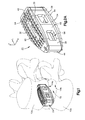
- Fig. 1 shows a superior vertebral body 10a which defines a first or superior vertebral surface 14a of an intervertebral space 18, and an adjacent second or inferior vertebral body 10b defines an inferior vertebral surface 14b of the intervertebral space 18.
- the intervertebral space 18 is disposed between or otherwise defined by the vertebral bodies 10a and 10b.
- the intervertebral space 18 can be disposed anywhere along the spine as desired, including at the lumbar, thoracic, and cervical regions of the spine.
- the intervertebral space 18 is illustrated after a discectomy, whereby the disc material has been removed or at least partially removed to prepare the intervertebral space 18 to receive an intervertebral implant, such as intervertebral implant 22 that can achieve height restoration for example as shown in Fig. 1 .
- the intervertebral implant can be configured as an interbody fusion implant and can be inserted into the intervertebral space 18 along an insertion direction such as from a posterior approach.
- the intervertebral implant 22 can however be inserted into the intervertebral space 18 along any insertion direction such as from an anterior approach.
- the intervertebral implant 22 is described herein as extending horizontally along a longitudinal direction “L” and lateral direction “A”, and vertically along a transverse direction “T".
- the terms “lateral”, “longitudinal”, and “transverse” are used to describe the orthogonal directional components of various components. While the longitudinal and lateral directions are illustrated as extending along a horizontal plane, and that the transverse direction is illustrated as extending along a vertical plane, the planes that encompass the various directions may differ during use.
- the transverse direction T extends vertically generally along the superior-inferior (or caudal-cranial) direction, while the horizontal plane defined by the longitudinal direction L and lateral direction A lies generally in the anatomical plane defined by the anterior-posterior direction, and the medial-lateral direction, respectively.
- the directional terms "vertical” and “horizontal” are used to describe the intervertebral implant 22 and its components as illustrated merely for the purposes of clarity and illustration.
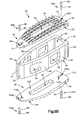
- the intervertebral implant 22 can include a core 26 that has a core body 28 that is elongate along a first direction, such as along the longitudinal direction L or along the insertion direction, and defines a first or upper outer surface 30 and a second or lower outer surface 34 that is spaced from the first outer surface 30 along a second direction that is perpendicular to the first direction, such as along the transverse direction T.
- the intervertebral implant can further include a first flexible end plate 36 coupled to the first outer surface 30 of the core body 28, and a second flexible end plate 38 coupled to the second outer surface of the core body 28. Both the first flexible end plate 36 and the second flexible end plate 38 are configured to resiliently flex toward the core when the intervertebral implant 22 is inserted into the intervertebral space 18.
- the core body 28 can define a first or posterior or rear end 40 and a second or anterior or front end 44 and can include a pair of side walls 48 that extend from the posterior end 40 to the anterior end 44.
- the side walls 48 can be spaced from each other along a third direction, such as along the lateral direction A, such that the core 26 defines a cage.
- the side walls 48 extend toward each other as the side walls 48 extend from the posterior end 40 toward the anterior end 44 so as to define a nose 52 at the anterior end 44.
- the core 26 can be rigid and can be made from any suitable bio-compatible material such as metal or plastic.
- the core 26 can be made from PEEK or titanium, as desired.
- the core 26 can further include at least one window 56 that extends through the core body 28 along the third direction such as through the side walls 48 along the third direction.
- the core 26 includes two windows 56 that extend through the core body 28.
- the core 26 can include any number of windows 56 and can alternatively be void of windows 56 as desired.
- the windows 56 are configured to promote boney in-growth.
- the core 26 can also include at least one channel 60 that extends through the core body 28 along the second direction from the first outer surface 30 to the second outer surface 34. As with the windows 56, the channel 60 is configured to at least promote boney in-growth.
- the first flexible end plate 36 defines an inner surface 62 and an opposed bone facing surface 64 that is configured to abut a vertebral body such as the vertebral body 10a when the intervertebral implant is disposed within the intervertebral space 18.
- the first flexible end plate 36 can be coupled to core 26 such that at least a portion of the inner surface 62 faces the first outer surface 30 and is spaced from the first outer surface 30 by a first distance D 1 .
- the first distance D 1 can be a maximum distance that the inner surface 62 is spaced from the first outer surface 30 and can be taken at a longitudinal midline of the first flexible end plate 36 (e.g. halfway between first and second ends of the first flexible endplate 36). However, the first distance D 1 can be taken at any point along the first flexible end plate 36.
- the first flexible end plate 36 can define a first or posterior end 70 and a second or anterior end 74 that is spaced from the first end 70 along the first direction.
- the first and second ends 70 and 74 can be coupled to the core body 28 such that the first flexible end plate 36 is bowed along the first direction.
- the flexible end plate 36 is flexible between a first or initial configuration and a second or compressed configuration such that as the end plate 36 flexes toward the compressed configuration the distance D 1 is decreased or the at least a portion of the inner surface 62 is spaced from the first outer surface 30 by a second distance that is less than the first distance D 1 .
- the first flexible end plate 36 is configured to resiliently flex toward the compressed configuration such that as the flexible end plate flexes toward the compressed configuration, the first end 70 moves along the core 26 or at least relative to the core 26 along the first direction and the portion of the inner surface 62 that faces the first outer surface 30 moves toward the first outer surface 30 such that the distance D 1 is decreased.
- the second end 74 is configured to move along the core 26 or at least relative to the core 26 along the first direction and away from the first end 70 when the first flexible end plate 36 flexes toward the compressed configuration.
- the distance D 1 can be between about 0.5 mm and about 10.0 mm and when in the compressed configuration the second distance can be about 0.0 mm.
- first and second distances can be any number as desired when the first flexible end plate 36 is in the initial configuration or in the compressed configuration.
- both the first and second ends 70 and 74 are configured to move along the first direction in the device shown in the drawings, one of the first and second ends 70 and 74 may be fixed.
- the first and second ends 70 and 74 of the first flexible end plate 36 can include first and second attachment members 79a and 79b such that the attachment members can be movably coupled to the core body 28 proximate to the posterior and anterior ends 40 and 44 of the core body 28.
- the first and second attachment members 79a and 79b can define first and second slots 80a and 80b, respectively, which are elongate along the first direction and are carried by the first and second ends 70 and 74, respectively.
- first and second attachment members 79a and 79b can define first and second slots 80a and 80b, respectively, which are elongate along the first direction and are carried by the first and second ends 70 and 74, respectively.
- implant 22, or at least the core 26 of the implant can include first and second fixation members 82a and 82b that extend through the first and second slots 80a and 80b and into the first outer surface 30 of the core body 28 to thereby couple the first flexible end plate 36 to the core body 28.
- the first flexible end plate 36 can be coupled to the core body 28 such that the first and second fixation members 82a and 82b limit the movement of the first and second ends 70 and 74 of the end plate 36 along the first direction when the flexible end plate 36 flexes toward the compressed configuration.
- the first and second fixation members 82a and 82b can be pins that couple to the core body 28 through an interference fit.
- the fixation members 82a and 82b can include a shaft 84 and a head 86 that extends out from an end of the shaft 84.
- the head 86 can be configured to have a dimension that is greater than that of a lateral dimension of the slots 80a and 80b and the shaft 84 can be configured to have a dimension that is less than the lateral dimension of the slots 80a and 80b. Therefore, the first and second ends 70 and 74 can be coupled to the core body 28 while at the same time be capable of translating along the first direction.
- fixation members 82a and 82b can have any configuration as desired.
- the fixation members 82a and 82b can be threaded.
- the first and second ends 70 and 74 can be coupled to the core body 28 with structure other than fixation members.
- the core body 28 can define slots that are configured to receive the first and second ends 70 and 74 as they translate.
- the first flexible end plate 36 can define a middle region 89 that extends from the first attachment member 79a to the second attachment member 79b.
- the first flexible end plate 36 can include at least one channel 90 that extends through the middle region 89 from the inner surface 62 to the bone facing surface 64 such that the at least one channel 60 of the core 26 and the at least one channel 90 of the flexible end plate 36 are substantially aligned along the second direction.
- the aligned channels 60 and 90 can help promote boney in-growth after the implant 22 has been inserted into the intervertebral space 18.
- the flexible end plate 36 can define a plurality of teeth 94 that extend out from the bone facing surface 64. The teeth 94 can be configured to prevent migration of the intervertebral implant 22 after the implant 22 has been inserted into the intervertebral space 18.
- first and second ends slide along the core 26
- an entirety of the middle region 89 can be spaced from the core 26 along the first direction.
- portions of the middle region 89 can be in contact with the core 26 as the first and second ends slide along the core 26.
- first and second attachment members 79a, 79b, or at least the first and second ends 70, 74 are shown as sliding along the first outer surface 30, the first and second attachment members 79a, 79b, or at least the first and second ends 70, 74, can slide along inner surfaces defined by the core 26.
- the second flexible end plate 38 can be substantially identical to the first flexible end plate 36 and can include like structure unless otherwise described.
- first and second flexible end plates 36, 38 are substantially identical in the device shown in the drawings, the end plates 36, 38 can include different structure and have different shapes as desired.
- the second flexible end plate 38 defines an inner surface 162 and an opposed bone facing surface 164 that is configured to abut a vertebral body such as vertebral body 10b.
- the second flexible end plate 38 can be coupled to core 26 such that at least a portion of the inner surface 162 faces the second outer surface 34 and is spaced from the second outer surface 34 by a third distance D 2 .
- the third distance D 2 can be a maximum distance that the inner surface 162 is spaced from the second outer surface 34 and can be taken at a longitudinal midline of the second flexible end plate 38 (e.g. halfway between first and second ends of the second flexible endplate 38).
- the second distance D 2 can be taken at any point along the second flexible end plate 38, as desired.
- the second flexible end plate 38 can define a first or posterior end 170 and a second or anterior end 174 that is spaced from the first end 170 along the first direction.
- the first and second ends 170 and 174 can be coupled to the core body 28 such that the second flexible end plate 38 is bowed along the first direction.
- the flexible end plate 38 is flexible between a first or initial configuration and a second or compressed configuration whereby the distance D 2 is decreased or the at least a portion of the inner surface 162 is spaced from the second outer surface 34 by a fourth distance that is less than the third distance.
- the second flexible end plate 38 is configured to resiliently flex toward the compressed configuration such that as the flexible end plate flexes toward the compressed configuration, the first end 170 moves relative to the core 26 along the first direction and the portion of the inner surface 162 moves toward the second outer surface 34 such that the distance D 2 is decreased.
- the second end 174 is configured to move relative to the core 26 along the first direction and away from the first end 170 when the second flexible end plate 38 flexes toward the compressed configuration.
- the third distance D 2 can be between about 0.5 mm and about 10.0 mm and when in the compressed configuration the fourth distance can be about 0.0 mm.
- the third and fourth distances can be any number as desired when the second flexible end plate 38 is in the initial configuration or in the compressed configuration.
- both the first and second ends 170, 174 are configured to move along the first direction in the device shown in the drawings, one of the first and second ends 170, 174 can be fixed.
- the first and second ends 170, 174 of the second flexible end plate 38 can be moveably coupled to the core body 28 proximate to the posterior and anterior ends 40, 44 of the core body 28.
- the second flexible end plate 38 can include first and second attachment members 179a, 179b such that the attachment members can be movably coupled to the core body 28 proximate to the posterior and anterior ends 40, 44 of the core body 28.
- the first and second attachment members 179a, 179b can define first and second slots 180a, 180b that are elongate along the first direction and located proximate to the first and second ends 70, 74, respectively.
- the core 26 can include third and fourth fixation members 182a, 182b that extend through the first and second slots 180a, 180b and into the second outer surface 34 of the core body 28 to thereby couple the second flexible end plate 38 to the core body 28 such that the third and fourth fixation members 182a, 182b limit the movement of the first and second ends 170, 174 along the first direction when the flexible end plate 38 flexes toward the compressed configuration.
- first and second flexible end plates 36, 38 can be coupled to the core body 28 using a first fixation member that extends through the core body 28 and through both first slots 80a, 180a, and a second fixation member that extends through the core body and through both second slots 80b, 180b.
- the first and second flexible end plates 36, 38 can be made from any bio-compatible material as desired.
- the first and second flexible end plates 36, 38 can be made from a bio-compatible metal such as titanium, steel, or any material that can provide spring-action.
- the first and second end plates 36, 38 can also have a stiffness that is configured to support or otherwise match the stiffness of the vertebral bodies 10a, 10b.
- the modulus of elasticity of cortical bone is between 7 and 30 GPa and the first and second endplates 36, 38 can have a stiffness that is configured to support this range of moduli. Therefore, the first and second endplates 36, 38 can have a stiffness that is between about 7 GPa and about 30 GPA.
- the first and second end plates 36, 38 can have any stiffness as desired.
- the modulus of elasticity of cancellous bone is 55.6 MPa and the first and second end plates 36, 38 can have a stiffness that is about 55.6 MPa so as to match the stiffness of the cancellous bone in the rare case that the cortical bone is lost and the cancellous bone is exposed.
- the stiffness of the end plates 36, 38 can be dependent on a variety of factors such as the material choice and the geometry of the end plates 36, 38.
- the implant 22 can be sold individually or as a kit that includes the core 26, a plurality of flexible end plates 36, 38, and a plurality of fixation members. At least one of the end plates 36, 38 can have a stiffness that is different than the stiffness of at least one of the other flexible end plates. However, some of the end plates of the plurality of end plates can have the same stiffness. Moreover, the end plates of the plurality of end plates can have different shapes, be made from different materials, and/or have different coupling features.
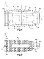
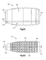
- Figs. 3A to 3F show an intervertebral implant 222 which includes a first end plate 226, a second end plate 230 coupled to the first end plate 226, and a biassing member 234 coupled between the first and second end plates 226 and 230 along a first direction.
- the first end plate 226 is configured to move relative to the second end plate 230 along the first direction, such as along the transverse direction, between an initial or first configuration and a compressed or second configuration and movement of the first end plate from the first configuration to the second configuration causes the biassing member 234 to compress so as to bias the first end palate along the first direction from the second configuration toward the first configuration.
- the first end plate 226 includes a first body 240 that is elongate along a second direction, such as along the longitudinal direction or insertion direction.
- the first body 240 defines a first bone facing surface 244 and a first inner or internal ceiling surface 248 that is spaced from the first bone facing surface 244 along a first direction, such as along the transverse direction.
- the first body 240 can define a first or posterior end 252 and a second or anterior end 256.
- the first end plate 226 can further include at least one wall that extends from the first body 240 substantially along the first direction.
- the first end plate 226 can include a pair of side walls 260 that extend from the posterior end 252 to the anterior end 256.
- the side walls 260 can extend toward each other as the side walls 260 extend from the posterior end 252 toward the anterior end 256 so as to define a nose 258 at the anterior end 256.
- the side walls 260 can be spaced from each other along a third direction, such as along the lateral direction A, such that the posterior end 252, the anterior end 256, and the side walls 260 define a cavity 264 of the first body. Therefore, the at least one wall can be a single continuous wall that includes the posterior end 252, anterior end 256, and side walls 260 such that the cavity 264 is at least partially defined by the at least one wall and the internal ceiling surface 248.
- the cavity 264 can be defined by a first pair of internal side surfaces 272 that are spaced along the second direction, and a second pair of internal side surfaces 276 that are spaced along the third direction. As shown, the internal side surfaces 272 of the first pair of side surfaces 272 are spaced from each other along the first direction by a distance D 3 .
- the distance D 3 can be any dimension as desired so long as the cavity 264 can receive a portion of the second end plate 230.
- the first end plate 226 further includes a recess 280 that extends into the internal ceiling surface 248 and toward the first bone facing surface 244.
- the recess 280 can be configured as a bore as illustrated and can be configured to receive a portion of the biassing member 234.
- the recess 280 can have any configuration as desired.
- the recess 280 can be substantially cubed shaped.
- the end plate 226 can include multiple recesses 280 if desired.
- the second end plate 230 includes a second body 340 that is elongate along the second direction, such as along the longitudinal direction.
- the second body 340 defines a second bone facing surface 344 and a second inner surface 348 that is spaced from the second bone facing surface 344 along the first direction, such as along the transverse direction.
- the second body 340 can define a first or posterior end 352 and a second or anterior end 356 that is spaced form the posterior end 352 along the second direction.
- At least a portion of the second body 340 defines a core 364 that is configured to be received by the cavity 264 of the first body 240 such that the internal ceiling surface 248 faces the second inner surface 348. Therefore, the core 364 can be said to define the second inner surface 348.
- the core 364 can define a first pair of external side surfaces 368 that are spaced along the second direction and a second pair of external side surfaces 372 that are spaced along the third direction.
- the second pair of side surfaces 372 extend toward each other as the side surfaces 372 extend from the posterior end 352 toward the anterior end 356 such that the core 364 defines a nose 370 at the anterior end 356.
- the external side surfaces 368 of the first pair of external side surfaces 368 are spaced from each other along the first direction by a distance D 4 .
- the distance D 4 can be substantially equal to the distance D 3 such that the core 364 can be received within the cavity 264.
- the distance D 4 can be any dimension as desired so long as the cavity 264 can receive the core 364 of the second end plate 230.
- the core 364 in the device shown in the drawing has shape that is substantially identical to that of the cavity 264, the shapes of the core and the cavity can be different so long as the cavity can receive the core.
- the anterior and posterior ends 252 and 256 can trap the core 364 within the cavity 264. Therefore, the anterior and posterior ends 252 and 256 can be said to be first and second attachment members. As the core 364 moves within the cavity 264, the first and second attachment members move or otherwise will slide along the core along the first direction.
- the second end plate 230 can further include a shoulder 380 that extends out from the second body 340 such that the shoulder 380 defines an abutment surface 384 that faces an end 385 of the at least one wall.
- the shoulder 380 can be configured to limit movement of the first end plate 226 relative to the second end plate 230 along the first direction when the end 385 abuts the abutment surface 384.
- the shoulder 380 can extend completely around the second body 340 and can be continuous as shown, or the shoulder 380 can be segmented as desired.
- the internal ceiling surface 248 can abut the second inner surface 348 so as to limit the movement of the first end plate 226 relative to the second end plate 230 along the first direction.
- the second end plate 230 further includes a recess 392 that extends into the second inner surface 348 and toward the second bone facing surface 344.
- the recess 392 can be configured as a bore as illustrated and can be configured to receive a portion of the biassing member 234.
- the recess 392 can have any configuration as desired.
- the recess 392 can be substantially cubed shaped.
- the second end plate can include any number of recesses 392 as desired.
- the first and second end plates 226 and 230 can be made from any bio-compatible material such as PEEK and/or titanium. Furthermore, at least one of the first end plate 226 and the second end plate 230 can include a radio-opaque marker 398 that is configured to indicate the position of the implant during implantation. In the device shown in the drawing, the first end plate 226 includes one marker 398 and the second end plate 230 includes two markers 398. However, the first and second end plates 226 and 230 can include any number of markers 398 as desired, in any direction as desired, and of any shape (e.g. pin, ball, etc) as desired.
- any shape e.g. pin, ball, etc
- first and second end plates 226 and 230 can define a plurality of teeth 400 that extend out from the bone facing surfaces 244 and 344.
- the teeth 400 can be configured to prevent migration of the intervertebral implant 222 after the implant 222 has been inserted into the intervertebral space 18.
- the first and second endplates 226 and 230 can define channels and windows similar to those of the implant 22 to thereby further promote boney in-growth.
- the biassing member 234 can be positioned in the recesses 280 and 392 of the first and second end plates 226 and 230. Therefore, the recess 280 of the first end plate 226 can be coaxial with the recess 392 of the second end plate 230 when the core 364 is received by the cavity 264 such that the biassing member 234 is trapped within the recesses 280 and 392.
- the biassing member 234 can be a spring such as a circular compression spring as illustrated.
- the biassing member 234 can have any configuration as desired.
- the biassing member 234 can be configured as a solid compression member.
- the biassing member 234 can have a stiffness that is configured to support or otherwise match the stiffness of the vertebral bodies 10a and 10b.
- the modulus of elasticity of cortical bone is between 7 GPa and 30 GPa and the biassing member 234 can have a stiffness that is configured to support this range of moduli. Therefore, the biassing member 234 can have a stiffness that is between about 7 GPa and about 30 GPA.
- the biassing member 234 can have any stiffness as desired.
- the modulus of elasticity of cancellous bone is 55.6 MPa and the biassing member 234 can have a stiffness of about 55.6 MPa.
- the first end plate 226 when the first end plate 226 is coupled to the second end plate 230 at least one of the first end plate 226 and the second end plate 230 is configured to move relative to the other along the first or transverse direction between an initial or first configuration and a compressed or second configuration.
- the internal ceiling surface 248 When in the initial configuration, the internal ceiling surface 248 is spaced from the second inner surface 348 along the first direction by a first distance d 1 .
- the internal ceiling surface 248 When in the compressed configuration, the internal ceiling surface 248 is spaced from the second inner surface 348 along the second direction by a second distance d 2 that is less than the first distance d 1 . Therefore, it can be said that when the first end plate 226 moves toward the compressed configuration, the first distance d 1 decreases.
- the first distance d 1 can between about 0.5 mm and about 10.0 mm and the second distance d 2 can be about 0 mm.
- the first and second distances d 1 and d 2 can be any distances as desired.
- the biassing member 234 When in the compressed configuration, the biassing member 234 is configured to bias the first end plate 226 toward the initial configuration.
- the implant 222 can include more than one biassing member 234 as desired.
- the implant 222 can include two biassing members that bias the first end plate 226 toward the initial configuration.
- the first and second end plates 226 and 230 can be coupled together by the biassing member 234 or the at least one side wall can include fingers that engage the core so as to allow the core to move within the cavity along the first direction.
- the first and second end plates 226 and 230 can be coupled together using any structure as desired so long as the core is capable of moving along the first direction within the cavity.
- the implants 22 and 222 can substantially match the stiffness of the vertebral bodies 10a and 10b to thereby promote fusion. Because of the construction of the implants 22 and 222, the implants 22 and 222 can be customized to match a variety of stiffnesses. Therefore, it can be said that the implants 22 and 222 may be customizable or have adjustable stiffnesses. However, the implants 22 and 222 can be constructed to have a specified stiffness.
Landscapes
- Health & Medical Sciences (AREA)
- Engineering & Computer Science (AREA)
- Biomedical Technology (AREA)
- Neurology (AREA)
- Orthopedic Medicine & Surgery (AREA)
- Cardiology (AREA)
- Oral & Maxillofacial Surgery (AREA)
- Transplantation (AREA)
- Heart & Thoracic Surgery (AREA)
- Vascular Medicine (AREA)
- Life Sciences & Earth Sciences (AREA)
- Animal Behavior & Ethology (AREA)
- General Health & Medical Sciences (AREA)
- Public Health (AREA)
- Veterinary Medicine (AREA)
- Prostheses (AREA)
Applications Claiming Priority (2)
| Application Number | Priority Date | Filing Date | Title |
|---|---|---|---|
| US201261708247P | 2012-10-01 | 2012-10-01 | |
| US13/653,715 US9757247B2 (en) | 2012-10-01 | 2012-10-17 | Interbody fusion implant |
Publications (3)
| Publication Number | Publication Date |
|---|---|
| EP2732797A2 true EP2732797A2 (de) | 2014-05-21 |
| EP2732797A3 EP2732797A3 (de) | 2014-06-25 |
| EP2732797B1 EP2732797B1 (de) | 2020-06-10 |
Family
ID=50385919
Family Applications (1)
| Application Number | Title | Priority Date | Filing Date |
|---|---|---|---|
| EP13186838.2A Active EP2732797B1 (de) | 2012-10-01 | 2013-10-01 | Interkorporelles Fusionsimplantat |
Country Status (2)
| Country | Link |
|---|---|
| US (2) | US9757247B2 (de) |
| EP (1) | EP2732797B1 (de) |
Families Citing this family (15)
| Publication number | Priority date | Publication date | Assignee | Title |
|---|---|---|---|---|
| US9220547B2 (en) | 2009-03-27 | 2015-12-29 | Spinal Elements, Inc. | Flanged interbody fusion device |
| KR20150023455A (ko) | 2012-05-29 | 2015-03-05 | 엔엘티 스파인 리미티드. | 측면으로 휘어지는 임플란트 |
| FR3006170B1 (fr) * | 2013-05-31 | 2015-06-26 | Osd Orthopaedic & Spine Dev | Prothese intersomatique produisant un reglage de lordose individualise |
| US9198774B2 (en) * | 2013-11-21 | 2015-12-01 | Perumala Corporation | Intervertebral disk cage and stabilizer |
| TWI607736B (zh) * | 2013-11-29 | 2017-12-11 | 財團法人金屬工業研究發展中心 | Intervertebral implant and its manufacturing method |
| AU2016212009C1 (en) | 2015-01-27 | 2021-02-25 | Spinal Elements, Inc. | Facet joint implant |
| CN107949347B (zh) * | 2015-09-03 | 2020-08-14 | Cmc色特有限公司 | 用于替换人类的手或脚中关节的假体 |
| US10617531B2 (en) * | 2015-10-26 | 2020-04-14 | K2M, Inc. | Cervical disc and instrumentation |
| KR102873477B1 (ko) * | 2016-12-28 | 2025-10-20 | 엘지디스플레이 주식회사 | 표시 장치용 기판과 그를 포함하는 표시 장치 |
| AU2018267562B2 (en) | 2017-11-24 | 2019-10-03 | Prism Surgical Designs Pty Ltd | Vertebral column implant |
| CA3111008A1 (en) | 2018-09-20 | 2020-03-26 | Spinal Elements, Inc. | Spinal implant device |
| CA3063846A1 (en) | 2018-12-05 | 2020-06-05 | Smed-Ta/Td, Llc | Adjusted stiffness orthopaedic implants and method of manufacture |
| KR102367057B1 (ko) * | 2019-12-23 | 2022-02-25 | 유앤아이 주식회사 | 척추 유합술용 임플란트 |
| US11911284B2 (en) | 2020-11-19 | 2024-02-27 | Spinal Elements, Inc. | Curved expandable interbody devices and deployment tools |
| US12279969B2 (en) | 2020-12-17 | 2025-04-22 | Spinal Elements, Inc. | Spinal implant device |
Family Cites Families (35)
| Publication number | Priority date | Publication date | Assignee | Title |
|---|---|---|---|---|
| US4309777A (en) * | 1980-11-13 | 1982-01-12 | Patil Arun A | Artificial intervertebral disc |
| CA1283501C (en) * | 1987-02-12 | 1991-04-30 | Thomas P. Hedman | Artificial spinal disc |
| US7879095B2 (en) * | 1994-03-18 | 2011-02-01 | Madhavan Pisharodi | Method of inserting, rotating and releasing a spring-loaded artificial disk |
| FR2728159B1 (fr) * | 1994-12-16 | 1997-06-27 | Tornier Sa | Prothese discale elastique |
| ES2301219T3 (es) | 1998-10-20 | 2008-06-16 | Synthes Gmbh | Caja de artrodesis vertebral reguladora de compresion para cirugia de soldadura. |
| US6419705B1 (en) * | 1999-06-23 | 2002-07-16 | Sulzer Spine-Tech Inc. | Expandable fusion device and method |
| US6454806B1 (en) * | 1999-07-26 | 2002-09-24 | Advanced Prosthetic Technologies, Inc. | Spinal surgical prosthesis |
| US6673113B2 (en) * | 2001-10-18 | 2004-01-06 | Spinecore, Inc. | Intervertebral spacer device having arch shaped spring elements |
| US6974480B2 (en) * | 2001-05-03 | 2005-12-13 | Synthes (Usa) | Intervertebral implant for transforaminal posterior lumbar interbody fusion procedure |
| DE10132588C2 (de) * | 2001-07-05 | 2003-05-22 | Fehling Instr Gmbh | Bandscheibenprothese |
| ATE398430T1 (de) * | 2001-08-24 | 2008-07-15 | Zimmer Gmbh | Künstliche bandscheibe |
| WO2003032801A2 (en) | 2001-10-18 | 2003-04-24 | Third Millennium Engineering Llc | Artificial intervertebral disc having a spider spring force restoring element |
| US20040024461A1 (en) * | 2002-05-10 | 2004-02-05 | Ferree Bret A. | Spring and spherical joint artificial disc replacements |
| WO2004016217A2 (en) * | 2002-08-15 | 2004-02-26 | David Gerber | Controlled artificial intervertebral disc implant |
| US7458988B2 (en) | 2003-11-05 | 2008-12-02 | Warsaw Orthopedic, Inc. | Compressible corpectomy device |
| US7214244B2 (en) | 2004-02-19 | 2007-05-08 | Spinecore, Inc. | Artificial intervertebral disc having an articulating joint |
| EP1729691B1 (de) * | 2004-04-02 | 2010-05-05 | Synthes GmbH | Bandscheibenprothese oder künstlicher wirbelkörper |
| US8597360B2 (en) * | 2004-11-03 | 2013-12-03 | Neuropro Technologies, Inc. | Bone fusion device |
| KR101105959B1 (ko) * | 2005-10-10 | 2012-01-18 | 도나 진 카버 | 인공추간판 치환시스템 및 방법 |
| US8236055B2 (en) | 2005-12-16 | 2012-08-07 | Seaspine, Inc. | Intervertebral prosthesis for supporting adjacent vertebral bodies enabling the creation of soft fusion and method |
| ATE444041T1 (de) * | 2006-04-28 | 2009-10-15 | Concept Matrix Llc | Zweikomponenten-wirbelfixationsvorrichtung |
| US8016886B2 (en) | 2006-07-18 | 2011-09-13 | Altus Partners, Llc | Intervertebral disc replacement device |
| US8029574B2 (en) | 2006-11-07 | 2011-10-04 | Biomedflex Llc | Prosthetic knee joint |
| US20080177389A1 (en) * | 2006-12-21 | 2008-07-24 | Rob Gene Parrish | Intervertebral disc spacer |
| US20080167686A1 (en) | 2007-01-05 | 2008-07-10 | Warsaw Orthopedic, Inc. | Non-Rigid Intervertebral Spacers |
| JP5406209B2 (ja) * | 2007-12-12 | 2014-02-05 | インテリジェント インプラント システムズ | 荷重分散椎体間固定装置 |
| EP2244671A4 (de) * | 2008-01-25 | 2013-03-20 | Spinalmotion Inc | Intervertebrale prothesescheibe mit stossdämpfendem, mit scheibenfedern ausgebildetem kern |
| US20100145455A1 (en) * | 2008-12-10 | 2010-06-10 | Innvotec Surgical, Inc. | Lockable spinal implant |
| US20100004748A1 (en) | 2008-07-03 | 2010-01-07 | Cordaro Nicholas M | Intervertebral prosthesis |
| US8172902B2 (en) | 2008-07-17 | 2012-05-08 | Spinemedica, Llc | Spinal interbody spacers |
| WO2010141910A2 (en) | 2009-06-05 | 2010-12-09 | Magellan Spine Technologies, Inc. | Spinal implants and methods |
| US8679183B2 (en) * | 2010-06-25 | 2014-03-25 | Globus Medical | Expandable fusion device and method of installation thereof |
| US20110112644A1 (en) | 2009-11-12 | 2011-05-12 | Zilberstein Boris | Disc prosthetic implant device |
| US8287598B1 (en) * | 2011-12-05 | 2012-10-16 | TrueMotion Spine, Inc. | True spinal motion preserving, shock absorbing, intervertebral spinal disc prosthesis |
| KR20150023455A (ko) * | 2012-05-29 | 2015-03-05 | 엔엘티 스파인 리미티드. | 측면으로 휘어지는 임플란트 |
-
2012
- 2012-10-17 US US13/653,715 patent/US9757247B2/en active Active
-
2013
- 2013-10-01 EP EP13186838.2A patent/EP2732797B1/de active Active
-
2017
- 2017-08-11 US US15/674,961 patent/US11135068B2/en active Active
Non-Patent Citations (1)
| Title |
|---|
| None |
Also Published As
| Publication number | Publication date |
|---|---|
| EP2732797A3 (de) | 2014-06-25 |
| US20180000610A1 (en) | 2018-01-04 |
| US9757247B2 (en) | 2017-09-12 |
| US11135068B2 (en) | 2021-10-05 |
| US20140094919A1 (en) | 2014-04-03 |
| EP2732797B1 (de) | 2020-06-10 |
Similar Documents
| Publication | Publication Date | Title |
|---|---|---|
| EP2732797B1 (de) | Interkorporelles Fusionsimplantat | |
| US12042398B2 (en) | Interbody standalone intervertebral implant | |
| USRE47470E1 (en) | Vertebral body placement and method for spanning a space formed upon removal of a vertebral body | |
| CN103648421B (zh) | 椎体间间隔物 | |
| EP2442756B1 (de) | Bandscheibenimplantat | |
| US10548741B2 (en) | Distractible intervertebral implant | |
| EP2477579B1 (de) | Zwischenwirbelimplantat mit ausstellbaren Knochenbefestigungselementen | |
| US8216314B2 (en) | Distractable spinal implant assembly | |
| EP2376028B1 (de) | Orthopädisches implantat mit flexiblem kiel | |
| EP2677969B1 (de) | Expandierbares interkorporelles fusionsimplantat | |
| US20230293311A1 (en) | Standalone anterior lumber interbody spacer | |
| CN103338727A (zh) | 带有模块化附加装置的椎体间脊柱植入物 | |
| US12290444B2 (en) | Intervertebral implants having positioning grooves and kits and methods of use thereof | |
| US12029657B2 (en) | Intervertebral devices |
Legal Events
| Date | Code | Title | Description |
|---|---|---|---|
| PUAI | Public reference made under article 153(3) epc to a published international application that has entered the european phase |
Free format text: ORIGINAL CODE: 0009012 |
|
| 17P | Request for examination filed |
Effective date: 20131001 |
|
| AK | Designated contracting states |
Kind code of ref document: A2 Designated state(s): AL AT BE BG CH CY CZ DE DK EE ES FI FR GB GR HR HU IE IS IT LI LT LU LV MC MK MT NL NO PL PT RO RS SE SI SK SM TR |
|
| AX | Request for extension of the european patent |
Extension state: BA ME |
|
| PUAL | Search report despatched |
Free format text: ORIGINAL CODE: 0009013 |
|
| AK | Designated contracting states |
Kind code of ref document: A3 Designated state(s): AL AT BE BG CH CY CZ DE DK EE ES FI FR GB GR HR HU IE IS IT LI LT LU LV MC MK MT NL NO PL PT RO RS SE SI SK SM TR |
|
| AX | Request for extension of the european patent |
Extension state: BA ME |
|
| RIC1 | Information provided on ipc code assigned before grant |
Ipc: A61F 2/44 20060101AFI20140519BHEP |
|
| R17P | Request for examination filed (corrected) |
Effective date: 20141021 |
|
| RBV | Designated contracting states (corrected) |
Designated state(s): AL AT BE BG CH CY CZ DE DK EE ES FI FR GB GR HR HU IE IS IT LI LT LU LV MC MK MT NL NO PL PT RO RS SE SI SK SM TR |
|
| STAA | Information on the status of an ep patent application or granted ep patent |
Free format text: STATUS: EXAMINATION IS IN PROGRESS |
|
| 17Q | First examination report despatched |
Effective date: 20170316 |
|
| GRAP | Despatch of communication of intention to grant a patent |
Free format text: ORIGINAL CODE: EPIDOSNIGR1 |
|
| STAA | Information on the status of an ep patent application or granted ep patent |
Free format text: STATUS: GRANT OF PATENT IS INTENDED |
|
| INTG | Intention to grant announced |
Effective date: 20200131 |
|
| GRAS | Grant fee paid |
Free format text: ORIGINAL CODE: EPIDOSNIGR3 |
|
| GRAA | (expected) grant |
Free format text: ORIGINAL CODE: 0009210 |
|
| STAA | Information on the status of an ep patent application or granted ep patent |
Free format text: STATUS: THE PATENT HAS BEEN GRANTED |
|
| AK | Designated contracting states |
Kind code of ref document: B1 Designated state(s): AL AT BE BG CH CY CZ DE DK EE ES FI FR GB GR HR HU IE IS IT LI LT LU LV MC MK MT NL NO PL PT RO RS SE SI SK SM TR |
|
| REG | Reference to a national code |
Ref country code: GB Ref legal event code: FG4D |
|
| REG | Reference to a national code |
Ref country code: CH Ref legal event code: EP Ref country code: CH Ref legal event code: NV Representative=s name: E. BLUM AND CO. AG PATENT- UND MARKENANWAELTE , CH Ref country code: AT Ref legal event code: REF Ref document number: 1278628 Country of ref document: AT Kind code of ref document: T Effective date: 20200615 |
|
| REG | Reference to a national code |
Ref country code: DE Ref legal event code: R096 Ref document number: 602013069734 Country of ref document: DE |
|
| REG | Reference to a national code |
Ref country code: IE Ref legal event code: FG4D |
|
| REG | Reference to a national code |
Ref country code: LT Ref legal event code: MG4D |
|
| PG25 | Lapsed in a contracting state [announced via postgrant information from national office to epo] |
Ref country code: GR Free format text: LAPSE BECAUSE OF FAILURE TO SUBMIT A TRANSLATION OF THE DESCRIPTION OR TO PAY THE FEE WITHIN THE PRESCRIBED TIME-LIMIT Effective date: 20200911 Ref country code: NO Free format text: LAPSE BECAUSE OF FAILURE TO SUBMIT A TRANSLATION OF THE DESCRIPTION OR TO PAY THE FEE WITHIN THE PRESCRIBED TIME-LIMIT Effective date: 20200910 Ref country code: LT Free format text: LAPSE BECAUSE OF FAILURE TO SUBMIT A TRANSLATION OF THE DESCRIPTION OR TO PAY THE FEE WITHIN THE PRESCRIBED TIME-LIMIT Effective date: 20200610 Ref country code: SE Free format text: LAPSE BECAUSE OF FAILURE TO SUBMIT A TRANSLATION OF THE DESCRIPTION OR TO PAY THE FEE WITHIN THE PRESCRIBED TIME-LIMIT Effective date: 20200610 Ref country code: FI Free format text: LAPSE BECAUSE OF FAILURE TO SUBMIT A TRANSLATION OF THE DESCRIPTION OR TO PAY THE FEE WITHIN THE PRESCRIBED TIME-LIMIT Effective date: 20200610 |
|
| REG | Reference to a national code |
Ref country code: NL Ref legal event code: MP Effective date: 20200610 |
|
| PG25 | Lapsed in a contracting state [announced via postgrant information from national office to epo] |
Ref country code: HR Free format text: LAPSE BECAUSE OF FAILURE TO SUBMIT A TRANSLATION OF THE DESCRIPTION OR TO PAY THE FEE WITHIN THE PRESCRIBED TIME-LIMIT Effective date: 20200610 Ref country code: LV Free format text: LAPSE BECAUSE OF FAILURE TO SUBMIT A TRANSLATION OF THE DESCRIPTION OR TO PAY THE FEE WITHIN THE PRESCRIBED TIME-LIMIT Effective date: 20200610 Ref country code: BG Free format text: LAPSE BECAUSE OF FAILURE TO SUBMIT A TRANSLATION OF THE DESCRIPTION OR TO PAY THE FEE WITHIN THE PRESCRIBED TIME-LIMIT Effective date: 20200910 Ref country code: RS Free format text: LAPSE BECAUSE OF FAILURE TO SUBMIT A TRANSLATION OF THE DESCRIPTION OR TO PAY THE FEE WITHIN THE PRESCRIBED TIME-LIMIT Effective date: 20200610 |
|
| REG | Reference to a national code |
Ref country code: AT Ref legal event code: MK05 Ref document number: 1278628 Country of ref document: AT Kind code of ref document: T Effective date: 20200610 |
|
| PG25 | Lapsed in a contracting state [announced via postgrant information from national office to epo] |
Ref country code: AL Free format text: LAPSE BECAUSE OF FAILURE TO SUBMIT A TRANSLATION OF THE DESCRIPTION OR TO PAY THE FEE WITHIN THE PRESCRIBED TIME-LIMIT Effective date: 20200610 Ref country code: NL Free format text: LAPSE BECAUSE OF FAILURE TO SUBMIT A TRANSLATION OF THE DESCRIPTION OR TO PAY THE FEE WITHIN THE PRESCRIBED TIME-LIMIT Effective date: 20200610 |
|
| PG25 | Lapsed in a contracting state [announced via postgrant information from national office to epo] |
Ref country code: CZ Free format text: LAPSE BECAUSE OF FAILURE TO SUBMIT A TRANSLATION OF THE DESCRIPTION OR TO PAY THE FEE WITHIN THE PRESCRIBED TIME-LIMIT Effective date: 20200610 Ref country code: RO Free format text: LAPSE BECAUSE OF FAILURE TO SUBMIT A TRANSLATION OF THE DESCRIPTION OR TO PAY THE FEE WITHIN THE PRESCRIBED TIME-LIMIT Effective date: 20200610 Ref country code: ES Free format text: LAPSE BECAUSE OF FAILURE TO SUBMIT A TRANSLATION OF THE DESCRIPTION OR TO PAY THE FEE WITHIN THE PRESCRIBED TIME-LIMIT Effective date: 20200610 Ref country code: PT Free format text: LAPSE BECAUSE OF FAILURE TO SUBMIT A TRANSLATION OF THE DESCRIPTION OR TO PAY THE FEE WITHIN THE PRESCRIBED TIME-LIMIT Effective date: 20201012 Ref country code: EE Free format text: LAPSE BECAUSE OF FAILURE TO SUBMIT A TRANSLATION OF THE DESCRIPTION OR TO PAY THE FEE WITHIN THE PRESCRIBED TIME-LIMIT Effective date: 20200610 Ref country code: SM Free format text: LAPSE BECAUSE OF FAILURE TO SUBMIT A TRANSLATION OF THE DESCRIPTION OR TO PAY THE FEE WITHIN THE PRESCRIBED TIME-LIMIT Effective date: 20200610 Ref country code: IT Free format text: LAPSE BECAUSE OF FAILURE TO SUBMIT A TRANSLATION OF THE DESCRIPTION OR TO PAY THE FEE WITHIN THE PRESCRIBED TIME-LIMIT Effective date: 20200610 Ref country code: AT Free format text: LAPSE BECAUSE OF FAILURE TO SUBMIT A TRANSLATION OF THE DESCRIPTION OR TO PAY THE FEE WITHIN THE PRESCRIBED TIME-LIMIT Effective date: 20200610 |
|
| PG25 | Lapsed in a contracting state [announced via postgrant information from national office to epo] |
Ref country code: PL Free format text: LAPSE BECAUSE OF FAILURE TO SUBMIT A TRANSLATION OF THE DESCRIPTION OR TO PAY THE FEE WITHIN THE PRESCRIBED TIME-LIMIT Effective date: 20200610 Ref country code: SK Free format text: LAPSE BECAUSE OF FAILURE TO SUBMIT A TRANSLATION OF THE DESCRIPTION OR TO PAY THE FEE WITHIN THE PRESCRIBED TIME-LIMIT Effective date: 20200610 Ref country code: IS Free format text: LAPSE BECAUSE OF FAILURE TO SUBMIT A TRANSLATION OF THE DESCRIPTION OR TO PAY THE FEE WITHIN THE PRESCRIBED TIME-LIMIT Effective date: 20201010 |
|
| REG | Reference to a national code |
Ref country code: DE Ref legal event code: R097 Ref document number: 602013069734 Country of ref document: DE |
|
| PLBE | No opposition filed within time limit |
Free format text: ORIGINAL CODE: 0009261 |
|
| STAA | Information on the status of an ep patent application or granted ep patent |
Free format text: STATUS: NO OPPOSITION FILED WITHIN TIME LIMIT |
|
| PG25 | Lapsed in a contracting state [announced via postgrant information from national office to epo] |
Ref country code: DK Free format text: LAPSE BECAUSE OF FAILURE TO SUBMIT A TRANSLATION OF THE DESCRIPTION OR TO PAY THE FEE WITHIN THE PRESCRIBED TIME-LIMIT Effective date: 20200610 |
|
| 26N | No opposition filed |
Effective date: 20210311 |
|
| PG25 | Lapsed in a contracting state [announced via postgrant information from national office to epo] |
Ref country code: SI Free format text: LAPSE BECAUSE OF FAILURE TO SUBMIT A TRANSLATION OF THE DESCRIPTION OR TO PAY THE FEE WITHIN THE PRESCRIBED TIME-LIMIT Effective date: 20200610 |
|
| PG25 | Lapsed in a contracting state [announced via postgrant information from national office to epo] |
Ref country code: MC Free format text: LAPSE BECAUSE OF FAILURE TO SUBMIT A TRANSLATION OF THE DESCRIPTION OR TO PAY THE FEE WITHIN THE PRESCRIBED TIME-LIMIT Effective date: 20200610 Ref country code: LU Free format text: LAPSE BECAUSE OF NON-PAYMENT OF DUE FEES Effective date: 20201001 |
|
| REG | Reference to a national code |
Ref country code: BE Ref legal event code: MM Effective date: 20201031 |
|
| PG25 | Lapsed in a contracting state [announced via postgrant information from national office to epo] |
Ref country code: FR Free format text: LAPSE BECAUSE OF NON-PAYMENT OF DUE FEES Effective date: 20201031 |
|
| PG25 | Lapsed in a contracting state [announced via postgrant information from national office to epo] |
Ref country code: BE Free format text: LAPSE BECAUSE OF NON-PAYMENT OF DUE FEES Effective date: 20201031 |
|
| PG25 | Lapsed in a contracting state [announced via postgrant information from national office to epo] |
Ref country code: IE Free format text: LAPSE BECAUSE OF NON-PAYMENT OF DUE FEES Effective date: 20201001 |
|
| PG25 | Lapsed in a contracting state [announced via postgrant information from national office to epo] |
Ref country code: TR Free format text: LAPSE BECAUSE OF FAILURE TO SUBMIT A TRANSLATION OF THE DESCRIPTION OR TO PAY THE FEE WITHIN THE PRESCRIBED TIME-LIMIT Effective date: 20200610 Ref country code: MT Free format text: LAPSE BECAUSE OF FAILURE TO SUBMIT A TRANSLATION OF THE DESCRIPTION OR TO PAY THE FEE WITHIN THE PRESCRIBED TIME-LIMIT Effective date: 20200610 Ref country code: CY Free format text: LAPSE BECAUSE OF FAILURE TO SUBMIT A TRANSLATION OF THE DESCRIPTION OR TO PAY THE FEE WITHIN THE PRESCRIBED TIME-LIMIT Effective date: 20200610 |
|
| PG25 | Lapsed in a contracting state [announced via postgrant information from national office to epo] |
Ref country code: MK Free format text: LAPSE BECAUSE OF FAILURE TO SUBMIT A TRANSLATION OF THE DESCRIPTION OR TO PAY THE FEE WITHIN THE PRESCRIBED TIME-LIMIT Effective date: 20200610 |
|
| PGFP | Annual fee paid to national office [announced via postgrant information from national office to epo] |
Ref country code: GB Payment date: 20250828 Year of fee payment: 13 |
|
| REG | Reference to a national code |
Ref country code: CH Ref legal event code: U11 Free format text: ST27 STATUS EVENT CODE: U-0-0-U10-U11 (AS PROVIDED BY THE NATIONAL OFFICE) Effective date: 20251101 |
|
| PGFP | Annual fee paid to national office [announced via postgrant information from national office to epo] |
Ref country code: DE Payment date: 20250902 Year of fee payment: 13 |
|
| PGFP | Annual fee paid to national office [announced via postgrant information from national office to epo] |
Ref country code: CH Payment date: 20251101 Year of fee payment: 13 |