EP2732099B1 - Vorrichtung zum aufbringen einer markierungsfolie auf eine fahrbahn - Google Patents
Vorrichtung zum aufbringen einer markierungsfolie auf eine fahrbahn Download PDFInfo
- Publication number
- EP2732099B1 EP2732099B1 EP13731283.1A EP13731283A EP2732099B1 EP 2732099 B1 EP2732099 B1 EP 2732099B1 EP 13731283 A EP13731283 A EP 13731283A EP 2732099 B1 EP2732099 B1 EP 2732099B1
- Authority
- EP
- European Patent Office
- Prior art keywords
- marking film
- conveying element
- roadway
- conveying
- marking
- Prior art date
- Legal status (The legal status is an assumption and is not a legal conclusion. Google has not performed a legal analysis and makes no representation as to the accuracy of the status listed.)
- Active
Links
- 238000005520 cutting process Methods 0.000 claims description 13
- 230000009977 dual effect Effects 0.000 claims 1
- 239000000853 adhesive Substances 0.000 description 9
- 230000001070 adhesive effect Effects 0.000 description 9
- 238000000034 method Methods 0.000 description 9
- 238000010276 construction Methods 0.000 description 2
- 239000003292 glue Substances 0.000 description 2
- 238000011900 installation process Methods 0.000 description 2
- 238000003825 pressing Methods 0.000 description 2
- 230000015572 biosynthetic process Effects 0.000 description 1
- 238000004140 cleaning Methods 0.000 description 1
- 238000002485 combustion reaction Methods 0.000 description 1
- 238000011161 development Methods 0.000 description 1
- 230000018109 developmental process Effects 0.000 description 1
- 238000004519 manufacturing process Methods 0.000 description 1
- 238000005096 rolling process Methods 0.000 description 1
- 230000007704 transition Effects 0.000 description 1
Images


Classifications
-
- E—FIXED CONSTRUCTIONS
- E01—CONSTRUCTION OF ROADS, RAILWAYS, OR BRIDGES
- E01C—CONSTRUCTION OF, OR SURFACES FOR, ROADS, SPORTS GROUNDS, OR THE LIKE; MACHINES OR AUXILIARY TOOLS FOR CONSTRUCTION OR REPAIR
- E01C23/00—Auxiliary devices or arrangements for constructing, repairing, reconditioning, or taking-up road or like surfaces
- E01C23/16—Devices for marking-out, applying, or forming traffic or like markings on finished paving; Protecting fresh markings
- E01C23/18—Devices for marking-out, applying, or forming traffic or like markings on finished paving; Protecting fresh markings for applying prefabricated markings
- E01C23/185—Tape- or sheet-shape markers or carriers
Definitions
- the present invention relates to a device for applying a marking film to a roadway, with a receptacle for the marking film and a feed device with a conveying element for feeding the marking film in the direction of the roadway.
- Marking films are widely used in road traffic today for marking roadways. In this case, marking films are used in particular for the transitional definition of lanes in the field of construction sites. Conventional marking films, for example thin or thick-film films, have an adhesive on one side, so that a secure adhesion to the road surface is ensured.
- a known device for applying a marking film to a roadway usually has a receptacle for the marking film, which is often a roller or roller on which a rolled up for laying marking film can be placed (see, eg US 4,317,696 ).
- the marking film is unrolled and conveyed via a feeder in the direction of the road.
- the feeding device has a conveying element, which is, for example, a conveyor belt or a roller or a toothed wheel.
- the marking film accordingly runs from its receptacle along the feed device and along the conveying element to the roadway.
- the present invention is therefore based on the object, a device of the type mentioned in such a way and further, that a fast and safe laying a marking film is made possible with structurally simple means.
- the above object is achieved by a device having the features of claim 1.
- the device of the aforementioned type is configured and further developed such that the conveying element is mounted in a guide such that the conveying element from a rest position - for contacting the marking film and for conveying the marking film in the direction of the roadway - towards the marking film and then back from the marking film away in the rest position movable
- a linear guide for a substantially translational movement.
- a linear guide which could be designed as a sliding bearing, allows a very safe movement of the conveying element in the desired direction.
- the shortest possible contact between the conveying element and the marking film is desired so that as little adhesive as possible can be transferred from the marking film to the conveying element.
- the conveying element is designed as a double slide with a lower and an upper sliding element.
- the sliding elements are of different lengths in the direction of the translational movement, so that the sliding elements can contact the marking film at different locations. In this way, a particularly secure conveying of the marking film towards the roadway can be realized. It has initially been recognized that the skillful design of the conveyor element, the above object is achieved in a surprisingly simple manner.
- the conveying element is mounted in a guide such that the conveying element - at Demand - from a rest position to the marking film and then back away from the marking film is movable into the rest position.
- the conveying element contacts the marking film and conveys the marking film in the direction of the roadway, until, for example, a laying roller of the device presses the marking film onto the roadway and glues the marking film onto the roadway.
- the marking film is virtually automatically removed from its roll due to its sticking to the roadway-without the conveying element still being required or unwound and laid on the roadway until the device stopped and / or the marking film is cut off.
- the conveyor element according to the invention is mounted in a guide in such a way that it is moved out of its rest position only for a brief contact and conveyance of the marking film and is subsequently returned to this rest position.
- the conveying element and the marking film - there is only a short-term contact between the conveying element and the marking film - namely during the conveying process - and a transfer of adhesive from the marking film onto the conveying element is possible only during this short time.
- a constant transition of glue as in the case of US 4,317,696 known device occurs, is thus avoided.
- the conveying element in the device according to the invention only very rarely or not at all must be cleaned of adhesive, resulting in the great advantage that a virtually uninterrupted laying of marking film along almost any desired length of the route is possible.
- the conveying element can be moved in different ways.
- the conveyor element could be assigned a manual, electric, pneumatic or hydraulic drive, so that a secure movement of the conveyor element from its rest position to the marking film is ensured back and forth in each case.
- a lower or higher degree of automation could be realized by means of a manual or electric, pneumatic or hydraulic drive.
- the conveying element could be formed as a flat slide for preferably linear contact with the marking film.
- a slider is very easy to manufacture and, with a correspondingly thin design, allows an almost linear contact area with the marking film. This minimizes the risk of undesired transfer of adhesive from the marking film to the conveying element or to the slide.
- the conveying element could have at one end a plurality of contact elements or tips for quasi-point contact with the marking film.
- the formation of several contact elements or tips further favors a secure engagement between the marking film and the conveying element and thus a safe conveying of the marking film by the conveying element.
- the feed device could have an abutment for the marking film contacted by the conveying element.
- it can be prevented that the marking film unintentionally escapes or is pushed away when it comes into contact with the conveying element, so that there is no longer sufficient for conveying Engagement between the conveying element and marking film is generated.
- Such an abutment could thus prevent evasion of the hanging of the feeder towards the road marking film. A secure engagement with this hanging end of the marking film would be guaranteed.
- the abutment could be formed as a roller or roller, against which the conveyor element presses the marking film during contact and possibly during conveying.
- the counter bearing could be realized as a stop element, for example. As a stop plate.
- the two sliding elements of the double slide could be clamped to one another at their end remote from the marking film, so that they both have a free end facing the marking film and yet could be moved together in the direction of the marking film and away from it again.
- a lower, longer sliding element could be moved against an abutment or a lower laying roller and an upper, shorter sliding element against a guide roller located higher than the laying roller, so that the marking film securely between the upper guide roller and the lower counter bearing or the lower Verlegerolle managed and / or promoted.
- the feed device could have a guiding and / or deflecting element for the conveying element, so that the conveying element additionally guided during its movement towards the marking film and / or towards the roadway can be distracted.
- the guiding and / or deflecting element could deflect the conveying element during its movement towards the marking film in a suitable manner downwards in the direction of the roadway and / or to an abutment and / or to a laying or guiding roller. This could be ensured in an elegant manner with respect to the direction exactly predetermined guiding and / or conveying the marking film.
- Such a guiding and / or deflecting element could be embodied as a strut or traverse arranged transversely to the direction of movement of the conveying element, on which the conveying element could slide in a suitable manner during its movement.
- the device could have a chassis with preferably a drive motor.
- the drive motor could be an internal combustion engine or an electric motor.
- a manual device that is pulled or moved by an operator along the roadway is also conceivable, provided that a particularly cost-effective device can be realized.
- the feeder could be associated with a cutting device for the marking film.
- the marking film could be cut and the device could be moved on to the next laying area. At the beginning of this laying area then the marking film is guided back to the road and the next installation process begins.
- the feed device could be assigned a preferably programmable control device.
- a control device could control the movement of the device along the roadway and / or the laying process and thus the feeding device and possibly the cutting device in a suitable manner, so that virtually an automatic laying of the marking film, for example. For the realization of marking marks, could take place. This can a particularly fast and safe laying of the marking film can be achieved.
- the conveying element could introduce the marking film to a running on the roadway laying roller of the device and virtually press it to this.
- the marking film with its non-adhesive side could nevertheless adhere sufficiently to the laying roller, so that the laying roller continues the marking film during a rotation of the laying roller or a movement of the device towards the roadway and then sticks it with the adhesive side on the roadway.
- the film could then be pressed by the laying roller on the road and so be laid continuously on the road. Another overrolling of the marking film to its attachment - eg. With an additional roller - is not required.
- the film could be pressed by means of the conveying element against a guide roller arranged above the laying roller and then cut off below the guide roller by the cutting device.
- the conveying element By pressing the marking film by means of the conveying element on the guide roller prevents the marking film slips off during cutting.
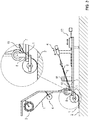
- Fig. 1 shows a schematic and perspective view of an embodiment of a device according to the invention for applying a marking film 1 on a roadway 2.
- the device has a receptacle 3 for the marking film 1 and a feeding device 4 with a conveying element 5 for feeding the marking film 1 in the direction of the roadway 2 ,
- the conveying element 5 is mounted in a guide 6 such that the conveying element 5 from a rest position - for contacting the marking film 1 and for conveying the marking film 1 in the direction of the lane 2 - towards the marking film 1 and then again away from the marking film 1 in the rest position is movable.
- the marking film 1 is mounted in a rolled-up form by the receptacle 3 and is guided by means of the feed device 4 via a roller assembly to the roadway.
- the conveying element 5 is mounted in a linear guide for a substantially translational movement.
- the conveying element 5 is manually moved away from the marking film 1 and away from the marking film 1 again.
- the direction of movement is shown by the double arrow in the region of the conveying element 5.
- the conveying element 5 is formed as a flat slide 7.
- the slide 7 can be moved in the direction of an abutment 8, wherein the abutment 8 is formed as a stop element 8.
- the slide 7 is designed as a double slide with a lower sliding element 9 and an upper sliding element 10, the sliding elements 9 and 10 are formed differently long in the direction of the translational movement and clamped at its end facing away from the marking film 1 end. At their end portions facing the marking film 1, both sliding elements 9 and 10 have tips for contact with the marking film 1. By this only point-only contact with the marking film 1 during the conveying process only very little adhesive from the marking film 1 reaches the sliding elements 9 and 10. An undesired sticking of the conveying element 5 and the sliding elements 9 and 10 is thus avoided.
- the conveying element 5 is further shifted to the marking film 1 out as in Fig. 2 shown state.
- the conveying element 5 is substantially in its rest position.
- the device could be coupled to a vehicle to be moved along the respective desired laying area of the roadway 2.
- the device could have its own chassis and its own drive motor.
- the feeding device 4 has a cutting device 12 for the marking film 1.
- the cutting device 12 essentially consists of a marking element 1 which is movable away from the marking film 1 and away from the marking film 1, which is movable along the double arrow shown in the region of the cutting device 12.
- the cutting device 12 can be guided up to the stop against the stop element 8, so that a secure cutting off of the marking film 1 can take place at the desired location.
- the device For secure pressing of the marking film 1 to be laid on the roadway 2, the device has a laying roller, which can be dimensioned such that a further rolling over and fixing the marking film 1 on the roadway 2 is not required.
- the laying roller is the lowest roller of the device, which presses the marking film 1 on the roadway 2.
- the feeding device 4 furthermore has a guiding and / or deflecting element 11 for the conveying element 5, so that the conveying element 5 can be guided during its movement towards the marking film 1 in addition to its bearing and / or can be deflected in the direction of the roadway 2.
- guiding and / or deflecting element 11 ensures that the slide 7 during operation of the device and during the movement of the slide 7 does not dodge upwards, but is guided safely in the direction of stop element 8 or Verlegerolle substantially.
- the guide and / the deflector 11 could push the slider 7 downwards, so that the translational movement effected by the linear guide is still experiencing a movement component directed in the direction of the lane 2 or downwards.
Description
- Die vorliegende Erfindung betrifft eine Vorrichtung zum Aufbringen einer Markierungsfolie auf eine Fahrbahn, mit einer Aufnahme für die Markierungsfolie und einer Zuführeinrichtung mit einem Förderelement zum Zuführen der Markierungsfolie in Richtung Fahrbahn.
- Markierungsfolien werden im heutigen Straßenverkehr in großem Umfang zur Markierung von Fahrbahnen verwendet. Dabei dienen Markierungsfolien insbesondere zur übergangsweisen Definierung von Fahrbahnen im Bereich von Baustellen. Übliche Markierungsfolien, bspw. Dünn- oder Dickschichtfolien, weisen auf einer Seite einen Klebstoff auf, so dass ein sicheres Anhaften auf der Fahrbahnoberfläche gewährleistet ist.
- Eine bekannte Vorrichtung zum Aufbringen einer Markierungsfolie auf eine Fahrbahn weist üblicherweise eine Aufnahme für die Markierungsfolie auf, wobei es sich hier häufig um eine Walze oder Rolle handelt, auf die eine zur Verlegung aufgerollte Markierungsfolie aufgesetzt werden kann (siehe z.B.
US 4 317 696 ). Während des Verlegens wird die Markierungsfolie abgerollt und über eine Zuführeinrichtung in Richtung Fahrbahn gefördert. Hierzu weist die Zuführeinrichtung ein Förderelement auf, wobei es sich hier bspw. um ein Förderband oder eine Walze oder ein Zahnrad handelt. Beim Verlegen der Markierungsfolie läuft die Markierungsfolie demnach von ihrer Aufnahme entlang der Zuführeinrichtung und entlang dem Förderelement bis zur Fahrbahn. - Bei der bekannten Vorrichtung ist problematisch, dass sich während des Zuführens und Förderns der Markierungsfolie in Richtung Fahrbahn im Laufe des Einsatzes der Vorrichtung ständig Klebstoff der Markierungsfolie am Förderelement absetzt. Dies hat zur Folge, dass das Förderelement schon nach relativ kurzer Einsatzzeit der Vorrichtung so stark verklebt, dass eine sichere Funktion der Zuführeinrichtung nicht mehr gewährleistet ist. Als Konsequenz müssen der Einsatz der Vorrichtung unterbrochen und das Förderelement gereinigt werden, um einen weiteren Einsatz der Vorrichtung zur ermöglichen. Dieser erforderliche Reinigungsvorgang reduziert die Effektivität und Leistung der Vorrichtung erheblich, so dass die Länge der pro Zeiteinheit mit einer Markierungsfolie belegbaren Strecke nicht zufriedenstellend ist. Somit muss deutlich mehr Zeit für das Verlegen der Markierungsfolie entlang einer gewünschten Strecke aufgewendet werden, als dies wünschenswert ist. Aus
US 4 242 173 ist eine ähnliche Vorrichtung bekannt, bei der die Zuführeinrichtung ein Förderelement in Form von Greifplatten aufweist, die nur kurzzeitig die Markierungsfolie kontaktieren und somit nicht stark verkleben. Die Konstruktion der Zuführeinrichtung ist jedoch kompliziert und daher wartungsanfällig. - Der vorliegenden Erfindung liegt daher die Aufgabe zugrunde, eine Vorrichtung der eingangs genannten Art derart auszugestalten und weiterzubilden, dass ein schnelles und sicheres Verlegen einer Markierungsfolie mit konstruktiv einfachen Mitteln ermöglicht ist.
- Die voranstehende Aufgabe wird durch eine Vorrichtung mit den Merkmalen des Anspruchs 1 gelöst. Danach ist die Vorrichtung der eingangs genannten Art derart ausgestaltet und weitergebildet, dass das Förderelement derart in einer Führung gelagert ist, dass das Förderelement aus einer Ruheposition - zum Kontaktieren der Markierungsfolie und zum Fördern der Markierungsfolie in Richtung Fahrbahn - zur Markierungsfolie hin und anschließend wieder von der Markierungsfolie weg in die Ruheposition bewegbar
- Im Hinblick auf eine besonders sichere Bewegbarkeit des Förderelements aus seiner Ruheposition zur Markierungsfolie hin und wieder zurück ist das Förderelement in einer Linearführung für eine im Wesentlichen translatorische Bewegung gelagert. Eine derartige Linearführung, die als Gleitlager ausgebildet sein könnte, ermöglicht eine sehr sichere Bewegung des Förderelements in der gewünschten Richtung. Ein möglichst kurzer Kontakt zwischen Förderelement und Markierungsfolie ist erwünscht, damit möglichst wenig Klebstoff von der Markierungsfolie auf das Förderelement übertragen werden kann.
- Das Förderelement ist als Doppelschieber mit einem unteren und einem oberen Schiebeelement ausgebildet. Die Schiebeelemente sind in Richtung der translatorischen Bewegung unterschiedlich lang ausgebildet, so dass die Schiebeelemente die Markierungsfolie an unterschiedlichen Stellen kontaktieren können. Hierdurch kann ein besonders sicheres Fördern der Markierungsfolie in Richtung Fahrbahn realisiert werden. Es ist zunächst erkannt worden, dass durch geschickte Ausgestaltung des Förderelements die voranstehende Aufgabe auf überraschend einfache Weise gelöst wird. Im Konkreten ist in weiter erfindungsgemäßer Weise das Förderelement derart in einer Führung gelagert, dass das Förderelement - bei Bedarf - aus einer Ruheposition zur Markierungsfolie hin und anschließend wieder von der Markierungsfolie weg in die Ruheposition bewegbar ist. Dabei ist es möglich, die Markierungsfolie insbesondere nach einem Abschneiden oder für ein erstmaliges Aufbringen der Markierungsfolie bei einem Verlegevorgang zur Fahrbahn hin zu führen. Dabei kontaktiert das Förderelement die Markierungsfolie und fördert die Markierungsfolie in Richtung Fahrbahn, bis bspw. eine Verlegerolle der Vorrichtung die Markierungsfolie auf die Fahrbahn presst und die Markierungsfolie auf der Fahrbahn festklebt. Bei einem Weiterbewegen der Vorrichtung wird die Markierungsfolie aufgrund ihres Festklebens auf der Fahrbahn dann quasi automatisch - ohne dass das Förderelement weiter benötigt wird - von ihrer Rolle abgezogen bzw. abgewickelt und weiter auf der Fahrbahn verlegt, bis die Vorrichtung angehalten und/oder die Markierungsfolie abgeschnitten wird. Mit anderen Worten ist das Förderelement in erfindungsgemäßer Weise derart in einer Führung gelagert, dass es lediglich zu einem kurzzeitigen Kontaktieren und Fördern der Markierungsfolie aus seiner Ruheposition bewegt wird und anschließend wieder in diese Ruheposition zurückgeführt wird. Während dieses Vorgangs herrscht nur ein kurzfristiger Kontakt zwischen dem Förderelement und der Markierungsfolie - nämlich während des Fördervorgangs - und ein Übergang von Klebstoff von der Markierungsfolie auf das Förderelement ist nur während dieser kurzen Zeit möglich. Ein ständiger Übergang von Klebstoff, wie er bei der aus
US 4 317 696 bekannten Vorrichtung auftritt, ist somit vermieden. Im Ergebnis muss das Förderelement bei der erfindungsgemäßen Vorrichtung nur sehr selten oder überhaupt nicht von Klebstoff gereinigt werden, woraus sich der große Vorteil ergibt, dass ein quasi unterbrechungsfreies Verlegen von Markierungsfolie entlang nahezu jeder gewünschten Streckenlänge ermöglicht ist. - Folglich ist mit der erfindungsgemäßen Vorrichtung eine Vorrichtung realisiert, bei der ein schnelles und sicheres Verlegen einer Markierungsfolie mit konstruktiv einfachen Mitteln ermöglicht ist.
- Das Förderelement kann auf unterschiedliche Weise bewegt werden. Hierzu könnte dem Förderelement ein manueller, elektrischer, pneumatischer oder hydraulischer Antrieb zugeordnet sein, so dass in jedem Fall eine sichere Bewegung des Förderelements aus seiner Ruheposition zur Markierungsfolie hin und wieder zurück gewährleistet ist. Je nach Erfordernis könnte ein geringerer oder höherer Automatisierungsgrad mittels eines manuellen oder elektrischen, pneumatischen oder hydraulischen Antriebs realisiert sein.
- Hinsichtlich eines besonders sicheren Kontaktierens und Förderns der Markierungsfolie könnte das Förderelement als flacher Schieber zum vorzugsweise linienförmigen Kontakt mit der Markierungsfolie ausgebildet sein. Ein derartiger Schieber ist in der Herstellung sehr einfach und ermöglicht bei entsprechend dünner Ausgestaltung einen nahezu linienförmigen Kontaktbereich mit der Markierungsfolie. Damit ist das Risiko eines unerwünschten Übergangs von Klebstoff von der Markierungsfolie auf das Förderelement bzw. auf den Schieber minimiert.
- In Hinblick auf eine noch kleinere Kontaktfläche oder auf noch weniger Berührungspunkte zwischen dem Förderelement und der Markierungsfolie könnte das Förderelement an einem Ende mehrere Kontaktelemente oder Spitzen zum quasi punktuellen Kontakt mit der Markierungsfolie aufweisen. Die Ausbildung von mehreren Kontaktelementen oder Spitzen begünstigt weiterhin einen sicheren Eingriff zwischen Markierungsfolie und Förderelement und damit ein sicheres Fördern der Markierungsfolie durch das Förderelement.
- Weiterhin im Hinblick auf ein besonders sicheres Fördern der Markierungsfolie und damit im Hinblick auf einen besonders sicheren Betrieb und ein sicheres Verlegen der Markierungsfolie könnte die Zuführeinrichtung ein Gegenlager für die von dem Förderelement kontaktierte Markierungsfolie aufweisen. Dabei kann verhindert werden, dass die Markierungsfolie bei Kontakt mit dem Förderelement ungewollt ausweicht oder weggedrückt wird, so dass kein für ein Fördern ausreichender Eingriff zwischen Förderelement und Markierungsfolie erzeugt wird. Ein derartiges Gegenlager könnte somit ein Ausweichen der von der Zuführeinrichtung in Richtung Fahrbahn hängenden Markierungsfolie verhindern. Ein sicherer Eingriff mit diesem hängenden Ende der Markierungsfolie wäre damit gewährleistet. In konstruktiv besonders einfacher Weise könnte das Gegenlager als Walze oder Rolle ausgebildet sein, gegen die das Förderelement die Markierungsfolie beim Kontakt und ggf. beim Fördern drückt. Alternativ hierzu und bei einer besonders einfachen Ausgestaltung könnte das Gegenlager als Anschlagelement, bspw. als Anschlagblech, realisiert sein.
- In weiter vorteilhafter Weise könnten die beiden Schiebeelemente des Doppelschiebers an ihrem der Markierungsfolie abgewandten Ende aneinander geklemmt sein, so dass sie beide ein der Markierungsfolie zugewandtes freies Ende aufweisen und dennoch gemeinsam in Richtung Markierungsfolie und von dieser wieder weg bewegt werden könnten. Ein unteres, längeres Schiebelement könnte gegen ein Gegenlager oder eine untere Verlegerolle und ein oberes, kürzeres Schiebeelement gegen eine weiter oben als die Verlegerolle angeordnete Führungsrolle bewegt werden, so dass die Markierungsfolie auf sichere Weise zwischen der oberen Führungsrolle und dem unteren Gegenlager oder der unteren Verlegerolle geführt und/oder gefördert werden könnte. In jedem Fall wäre sichergestellt, dass die Markierungsfolie mittels des Förderelements zuverlässig in Richtung Fahrbahn und/oder zu einem sicheren Verlegen auf der Fahrbahn gefördert werden könnte.
- Hinsichtlich einer besonders sicheren Bewegung des Förderelements zur Markierungsfolie und/oder von der Markierungsfolie wieder weg könnte die Zuführeinrichtung ein Führungs- und/oder Ablenkelement für das Förderelement aufweisen, so dass das Förderelement während seiner Bewegung zur Markierungsfolie hin zusätzlich geführt und/oder in Richtung Fahrbahn abgelenkt werden kann. Dabei könnte das Führungs- und/oder Ablenkelement das Förderelement während seiner Bewegung zur Markierungsfolie hin in geeigneter Weise nach unten in Richtung Fahrbahn und/oder zu einem Gegenlager und/oder zu einer Verlege- oder Führungsrolle hin ablenken. Hierdurch könnte auf elegante Weise ein hinsichtlich der Richtung exakt vorgegebenes Führen und/oder Fördern der Markierungsfolie gewährleistet werden. Ein derartiges Führungs- und/oder Ablenkelement könnte als quer zur Bewegungsrichtung des Förderelements angeordnete Strebe oder Traverse ausgebildet sein, an der das Förderelement während seiner Bewegung in geeigneter Weise entlang gleiten könnte.
- Im Hinblick auf eine besonders schnelle Verlegung einer Markierungsfolie könnte die Vorrichtung ein Fahrwerk mit vorzugsweise einem Antriebsmotor aufweisen. Dabei könnte der Antriebsmotor ein Verbrennungsmotor oder ein Elektromotor sein. Eine manuelle Vorrichtung, die durch einen Bediener entlang der Fahrbahn gezogen oder bewegt wird, ist jedoch auch denkbar, sofern eine besonders kostengünstige Vorrichtung zu realisieren ist.
- In Hinblick auf ein besonders schnelles und sicheres Verlegen von einzelnen Strichen auf einer Fahrbahn, bspw. zwischen zwei für die gleiche Fahrrichtung vorgesehenen Fahrbahnen, könnte der Zuführeinrichtung eine Schneideinrichtung für die Markierungsfolie zugeordnet sein. An geeigneter Position bzw. nach Verlegen einer gewünschten Länge an Markierungsfolie könnte die Markierungsfolie geschnitten und könnte die Vorrichtung bis zum nächsten Verlegebereich weiterbewegt werden. Zu Beginn dieses Verlegebereichs wird dann die Markierungsfolie wieder zur Fahrbahn hingeführt und der nächste Verlegevorgang beginnt.
- Bei einer besonders vorteilhaften Ausgestaltung der erfindungsgemäßen Vorrichtung könnte der Zuführeinrichtung eine vorzugsweise programmierbare Steuereinrichtung zugeordnet sein. Eine derartige Steuereinrichtung könnte die Bewegung der Vorrichtung entlang der Fahrbahn und/oder den Verlegevorgang und damit die Zuführeinrichtung und ggf. die Schneideinrichtung in geeigneter Weise steuern, so dass quasi ein automatisches Verlegen der Markierungsfolie, bspw. zur Realisierung von Markierungsstrichen, erfolgen könnte. Hierdurch kann ein besonders schnelles und sicheres Verlegen der Markierungsfolie erreicht werden.
- Bei einer vorteilhaften Ausgestaltung der erfindungsgemäßen Vorrichtung könnte das Förderelement die Markierungsfolie an eine auf der Fahrbahn laufende Verlegerolle der Vorrichtung heranführen und quasi an diese andrücken. Dabei könnte die Markierungsfolie mit ihrer nicht klebenden Seite dennoch in ausreichender Weise an der Verlegerolle anhaften, so dass die Verlegerolle die Markierungsfolie während einer Drehung der Verlegerolle bzw. eines Bewegens der Vorrichtung zur Fahrbahn hin weiterführt und dann mit der Klebeseite auf der Fahrbahn festklebt. Während des sich anschließenden Verlegevorgangs könnte die Folie dann durch die Verlegerolle auf die Fahrbahn gepresst und so kontinuierlich auf der Fahrbahn verlegt werden. Ein weiteres Überrollen der Markierungsfolie zu deren Befestigung - bspw. mit einer zusätzlichen Walze- ist nicht erforderlich.
- Zum Schneiden der Folie am Ende des Verlegevorgangs könnte die Folie mittels des Förderelements gegen eine oberhalb der Verlegerolle angeordnete Führungsrolle gedrückt und anschließend unterhalb der Führungsrolle durch die Schneideinrichtung abgeschnitten werden. Durch das Andrücken der Markierungsfolie mittels des Förderelements an der Führungsrolle wird verhindert, dass die Markierungsfolie beim Schneiden wegrutscht.
- Es gibt nun verschiedene Möglichkeiten, die Lehre der vorliegenden Erfindung in vorteilhafter Weise auszugestalten und weiterzubilden. Dazu ist einerseits auf die nachgeordneten Ansprüche und andererseits auf die nachfolgende Erläuterung eines bevorzugten Ausführungsbeispiels der Erfindung anhand der Zeichnung zu verweisen. In Verbindung mit der Erläuterung des bevorzugten Ausführungsbeispiels der Erfindung anhand der Zeichnung werden auch im Allgemeinen bevorzugte Ausgestaltungen und Weiterbildungen der Lehre erläutert. In der Zeichnung zeigen
- Fig. 1
- in einer perspektivischen Darstellung, schematisch, ein Ausführungsbeispiel einer erfindungsgemäßen Vorrichtung zum Aufbringen einer Markierungsfolie auf eine Fahrbahn,
- Fig. 2
- in einer Seitenansicht, schematisch, das Ausführungsbeispiel aus
Fig. 1 und - Fig. 3
- in einer Seitenansicht sowie in einer vergrößerten Detailansicht, schematisch, das Ausführungsbeispiel aus
Fig. 1 , wobei das Förderelement die Markierungsfolie in Richtung Fahrbahn fördert. -
Fig. 1 zeigt in einer schematischen und perspektivischen Darstellung ein Ausführungsbeispiel einer erfindungsgemäßen Vorrichtung zum Aufbringen einer Markierungsfolie 1 auf eine Fahrbahn 2. Die Vorrichtung weist eine Aufnahme 3 für die Markierungsfolie 1 und eine Zuführeinrichtung 4 mit einem Förderelement 5 zum Zuführen der Markierungsfolie 1 in Richtung Fahrbahn 2 auf. Im Hinblick auf ein schnelles und sicheres Verlegen der Markierungsfolie 1 mit konstruktiv einfachen Mitteln ist das Förderelement 5 derart in einer Führung 6 gelagert, dass das Förderelement 5 aus einer Ruheposition - zum Kontaktieren der Markierungsfolie 1 und zum Fördern der Markierungsfolie 1 in Richtung Fahrbahn 2 - zur Markierungsfolie 1 hin und anschließend wieder von der Markierungsfolie 1 weg in die Ruheposition bewegbar ist. - Die Markierungsfolie 1 ist dabei in zusammengerollter Form durch die Aufnahme 3 gelagert und wird mittels der Zuführeinrichtung 4 über eine Rollenanordnung zur Fahrbahn hin geführt.
- Wie auch der
Fig. 2 entnehmbar ist, die eine schematische Seitenansicht des Ausführungsbeispiels ausFig. 1 ist, ist das Förderelement 5 in einer Linearführung für eine im Wesentlichen translatorische Bewegung gelagert. Bei dem hier gezeigten Ausführungsbeispiel ist das Förderelement 5 manuell zur Markierungsfolie 1 hin und von der Markierungsfolie 1 wieder weg bewegbar. Die Bewegungsrichtung ist durch den Doppelpfeil im Bereich des Förderelements 5 dargestellt. - Im Konkreten ist das Förderelement 5 als flacher Schieber 7 ausgebildet. Der Schieber 7 kann in Richtung eines Gegenlagers 8 bewegt werden, wobei das Gegenlager 8 als Anschlagelement 8 ausgebildet ist.
- Im Konkreten ist der Schieber 7 als Doppelschieber mit einem unteren Schiebeelement 9 und einem oberen Schiebeelement 10 ausgebildet, wobei die Schiebeelemente 9 und 10 in Richtung der translatorischen Bewegung unterschiedlich lang ausgebildet und an ihrem der Markierungsfolie 1 abgewandten Ende aneinander geklemmt sind. An ihren der Markierungsfolie 1 zugewandten Endbereichen weisen beide Schiebeelemente 9 und 10 Spitzen zum Kontakt mit der Markierungsfolie 1 auf. Durch diesen jeweils lediglich punktförmigen Kontakt mit der Markierungsfolie 1 während des Fördervorgangs gelangt nur sehr wenig Klebstoff von der Markierungsfolie 1 auf die Schiebeelemente 9 und 10. Ein ungewünschtes Verkleben des Förderelements 5 bzw. der Schiebeelemente 9 und 10 ist somit vermieden.
- In der schematischen Seitenansicht und Detailansicht gemäß
Fig. 3 ist besonders gut erkennbar, dass der Schieber 7 und im Konkreten das untere Schiebeelement 9 bis in etwa zu dem Anschlagelement 8 hin verschiebbar ist. Hierdurch kann beim Fördervorgang verhindert werden, dass die Markierungsfolie 1 dem Fördervorgang ausweicht. Dieses Risiko des Ausweichens besteht, wenn die Markierungsfolie 1 erstmalig zur Fahrbahn 2 hin geführt werden soll oder nach einem Schnittvorgang zum Verlegen eines weiteren Markierungsstrichs wieder zur Fahrbahn 2 hingeführt werden soll. Es ist jedoch nicht zwingend, dass die Markierungsfolie 1 während des Fördervorgangs bis zum Anschlagelement 8 hin geführt werden muss. Je nach Ausgestaltung der Schiebeelemente 9 und 10 bzw. ganz allgemein des Förderelements 5 ist der durch den Kontakt zwischen Förderelement 5 und Markierungsfolie 1 erzeugte Eingriff bereits ausreichend, um die Markierungsfolie 1 in Richtung Fahrbahn 2 bewegen zu können. - Im in
Fig. 3 gezeigten Zustand ist das Förderelement 5 weiter zur Markierungsfolie 1 hin verschoben als im inFig. 2 gezeigten Zustand. InFig. 1 befindet sich das Förderelement 5 im Wesentlichen in seiner Ruheposition. - Die Vorrichtung könnte an ein Fahrzeug angekoppelt werden, um entlang des jeweils gewünschten Verlegebereichs der Fahrbahn 2 bewegt zu werden. Alternativ hierzu könnte die Vorrichtung ein eigenes Fahrwerk und einen eigenen Antriebsmotor aufweisen.
- Im Hinblick auf ein sicheres Verlegen einzelner Markierungsstriche weist die Zuführeinrichtung 4 eine Schneideinrichtung 12 für die Markierungsfolie 1 auf. Die Schneideinrichtung 12 besteht im Wesentlichen aus einem zur Markierungsfolie 1 hin und von der Markierungsfolie 1 wieder weg bewegbaren Messerelement, das entlang dem im Bereich der Schneideinrichtung 12 dargestellten Doppelpfeil bewegbar ist.
- Zum Abschneiden der Markierungsfolie 1 kann die Schneideinrichtung 12 bis zum Anschlag an das Anschlagelement 8 hin geführt werden, so dass ein sicheres Abschneiden der Markierungsfolie 1 an der gewünschten Stelle erfolgen kann.
- Zum sicheren Andrücken der zu verlegenden Markierungsfolie 1 auf der Fahrbahn 2 weist die Vorrichtung eine Verlegerolle auf, die derart dimensioniert sein kann, dass ein weiteres Überrollen und Fixieren der Markierungsfolie 1 auf der Fahrbahn 2 nicht erforderlich ist. Die Verlegerolle ist die unterste Rolle der Vorrichtung, die die Markierungsfolie 1 auf die Fahrbahn 2 drückt.
- Die Zuführeinrichtung 4 weist des Weiteren ein Führungs- und/oder Ablenkelement 11 für das Förderelement 5 auf, so dass das Förderelement 5 während seiner Bewegung zur Markierungsfolie 1 hin zusätzlich zu seiner Lagerung geführt und/oder in Richtung Fahrbahn 2 abgelenkt werden kann. Durch das Führungs- und/oder Ablenkelement 11 wird gewährleistet, dass der Schieber 7 beim Betrieb der Vorrichtung und bei der Bewegung des Schiebers 7 nicht nach oben ausweicht, sondern sicher im Wesentlichen in Richtung Anschlagelement 8 oder Verlegerolle geführt wird. Letztlich könnte das Führungs- und/der Ablenkelement 11 den Schieber 7 nach unten drücken, so dass die durch die Linearführung bewirkte translatorische Bewegung noch eine in Richtung Fahrbahn 2 oder nach unten gerichtete Bewegungskomponente erfährt.
- Hinsichtlich weiterer vorteilhafter Ausgestaltungen der erfindungsgemäßen Vorrichtung wird zur Vermeidung von Wiederholungen auf den allgemeinen Teil der Beschreibung sowie auf die beigefügten Ansprüche verwiesen.
- Schließlich sei ausdrücklich darauf hingewiesen, dass das voranstehend beschriebene Ausführungsbeispiel der erfindungsgemäßen Vorrichtung lediglich zur Erörterung der beanspruchten Lehre dient, diese jedoch nicht auf das Ausführungsbeispiel einschränkt.
-
- 1
- Markierungsfolie
- 2
- Fahrbahn
- 3
- Aufnahme
- 4
- Zuführeinrichtung
- 5
- Förderelement
- 6
- Führung
- 7
- Schieber
- 8
- Gegenlager / Anschlagelement
- 9
- unteres Schiebeelement
- 10
- oberes Schiebeelement
- 11
- Führungs- und/oder Ablenkelement
- 12
- Schneideinrichtung
Claims (8)
- Vorrichtung zum Aufbringen einer Markierungsfolie (1) auf eine Fahrbahn (2), mit einer Aufnahme (3) für die Markierungsfolie (1) und einer Zuführeinrichtung (4) mit einem Förderelement (5) zum Zuführen der Markierungsfolie (1) in Richtung Fahrbahn (2), wobei das Förderelement (5) derart in einer Führung (6) gelagert ist, dass das Förderelement (5) aus einer Ruheposition - zum Kontaktieren der Markierungsfolie (1) und zum Fördern der Markierungsfolie (1) in Richtung Fahrbahn (2) - zur Markierungsfolie (1) hin und anschließend wieder von der Markierungsfolie (1) weg in die Ruheposition bewegbar ist,
dadurch gekennzeichnet, dass die Führung (6) eine Linearführung für eine im Wesentlichen translatorische Bewegung ist und dass das Förderelement (5) als Doppelschieber mit einem unteren (9) und einem oberen (10) Schiebeelement ausgebildet ist, wobei die Schiebeelemente (9, 10) in Richtung der translatorischen Bewegung unterschiedlich lang ausgebildet sind. - Vorrichtung nach Anspruch 1, dadurch gekennzeichnet, dass dem Förderelement (5) ein manueller, elektrischer, pneumatischer oder hydraulischer Antrieb zugeordnet ist.
- Vorrichtung nach einem der Ansprüche 1 bis 2, dadurch gekennzeichnet, dass das Förderelement (5) als flacher Schieber (7) zum vorzugsweise linienförmigen Kontakt mit der Markierungsfolie (1) ausgebildet ist.
- Vorrichtung nach einem der Ansprüche 1 bis 3, dadurch gekennzeichnet, dass das Förderelement (5) an einem Ende mehrere Kontaktelemente oder Spitzen zum Kontakt mit der Markierungsfolie (1) aufweist.
- Vorrichtung nach einem der Ansprüche 1 bis 4, dadurch gekennzeichnet, dass die Zuführeinrichtung (4) ein Gegenlager (8) für die von dem Förderelement (5) kontaktierte Markierungsfolie (1) aufweist, wobei vorzugsweise das Gegenlager (8) als Walze oder Rolle oder Anschlagelement (8) ausgebildet ist.
- Vorrichtung nach einem der Ansprüche 1 bis 5, dadurch gekennzeichnet, dass die Zuführeinrichtung (4) ein Führungs- und/oder Ablenkelement (11) für das Förderelement (5) aufweist, so dass das Förderelement (5) während seiner Bewegung zur Markierungsfolie (1) hin zusätzlich geführt und/oder in Richtung Fahrbahn (2) abgelenkt werden kann.
- Vorrichtung nach einem der Ansprüche 1 bis 6, dadurch gekennzeichnet, dass die Vorrichtung ein Fahrwerk mit vorzugsweise einem Antriebsmotor aufweist.
- Vorrichtung nach einem der Ansprüche 1 bis 7, dadurch gekennzeichnet, dass der Zuführeinrichtung (4) eine Schneideinrichtung (12) für die Markierungsfolie (1) und/oder eine vorzugsweise programmierbare Steuereinrichtung zugeordnet ist.
Priority Applications (1)
| Application Number | Priority Date | Filing Date | Title |
|---|---|---|---|
| PL13731283T PL2732099T3 (pl) | 2012-04-27 | 2013-04-19 | Urządzenie do nanoszenia folii oznaczeniowej na jezdnię |
Applications Claiming Priority (2)
| Application Number | Priority Date | Filing Date | Title |
|---|---|---|---|
| DE102012207143A DE102012207143A1 (de) | 2012-04-27 | 2012-04-27 | Vorrichtung zum Aufbringen einer Markierungsfolie auf eine Fahrbahn |
| PCT/DE2013/200012 WO2013159774A2 (de) | 2012-04-27 | 2013-04-19 | Vorrichtung zum aufbringen einer markierungsfolie auf eine fahrbahn |
Publications (2)
| Publication Number | Publication Date |
|---|---|
| EP2732099A2 EP2732099A2 (de) | 2014-05-21 |
| EP2732099B1 true EP2732099B1 (de) | 2017-07-12 |
Family
ID=48698857
Family Applications (1)
| Application Number | Title | Priority Date | Filing Date |
|---|---|---|---|
| EP13731283.1A Active EP2732099B1 (de) | 2012-04-27 | 2013-04-19 | Vorrichtung zum aufbringen einer markierungsfolie auf eine fahrbahn |
Country Status (5)
| Country | Link |
|---|---|
| EP (1) | EP2732099B1 (de) |
| DE (1) | DE102012207143A1 (de) |
| ES (1) | ES2642344T3 (de) |
| PL (1) | PL2732099T3 (de) |
| WO (1) | WO2013159774A2 (de) |
Families Citing this family (2)
| Publication number | Priority date | Publication date | Assignee | Title |
|---|---|---|---|---|
| EP2944722B1 (de) * | 2014-05-12 | 2016-10-12 | TPA GmbH | Verfahren zur Herstellung einer Fahrbahndecke |
| CN114525729B (zh) * | 2021-12-17 | 2022-11-04 | 东南大学 | 一种用于大跨度桥梁形态激光扫描的辅助标记带铺设车 |
Family Cites Families (7)
| Publication number | Priority date | Publication date | Assignee | Title |
|---|---|---|---|---|
| US4030958A (en) * | 1976-08-09 | 1977-06-21 | Minnesota Mining And Manufacturing Company | Pavement-striping apparatus |
| US4242173A (en) * | 1979-09-27 | 1980-12-30 | Minnesota Mining And Manufacturing Company | Pavement-marking tape application apparatus |
| US4317696A (en) * | 1980-03-19 | 1982-03-02 | Prismo Universal Corporation | Apparatus for applying plastic tape |
| US4824516A (en) * | 1985-12-16 | 1989-04-25 | Seibu Polymer Kasei Kabushiki Kaishas | Pavement-marking tape applicator |
| FR2723753B3 (fr) * | 1994-08-22 | 1996-11-22 | Requena Julien | Dispositif autonome de pose de bandes autocollantes, en particulier pour le marquage de sols |
| DE4440688C1 (de) * | 1994-11-15 | 1996-02-08 | Hofmann Walter Maschf | Verfahren zur Verlegung von Markierungsbändern auf Straßen und Vorrichtung zur Durchführung des Verfahrens |
| FR2775010B1 (fr) * | 1998-02-16 | 2000-05-12 | Julien Requena | Dispositif autonome de pose de bandes, en particulier pour le marquage de sols |
-
2012
- 2012-04-27 DE DE102012207143A patent/DE102012207143A1/de not_active Ceased
-
2013
- 2013-04-19 EP EP13731283.1A patent/EP2732099B1/de active Active
- 2013-04-19 ES ES13731283.1T patent/ES2642344T3/es active Active
- 2013-04-19 PL PL13731283T patent/PL2732099T3/pl unknown
- 2013-04-19 WO PCT/DE2013/200012 patent/WO2013159774A2/de active Application Filing
Non-Patent Citations (1)
| Title |
|---|
| None * |
Also Published As
| Publication number | Publication date |
|---|---|
| WO2013159774A2 (de) | 2013-10-31 |
| PL2732099T3 (pl) | 2017-12-29 |
| EP2732099A2 (de) | 2014-05-21 |
| ES2642344T3 (es) | 2017-11-16 |
| DE102012207143A1 (de) | 2013-10-31 |
| WO2013159774A3 (de) | 2013-12-19 |
Similar Documents
| Publication | Publication Date | Title |
|---|---|---|
| DE102014207050A1 (de) | Splice-Vorrichtung | |
| EP2061702A1 (de) | Etikettieranlage | |
| EP1251092A2 (de) | Materialführungssystem für Spleissmaschinen | |
| AT518608B1 (de) | Kantenanleimvorrichtung | |
| EP2732099B1 (de) | Vorrichtung zum aufbringen einer markierungsfolie auf eine fahrbahn | |
| DE2800846A1 (de) | Vorrichtung zum aufbringen von abschlussblaettern o. dgl. auf blattlagen | |
| EP2127828B1 (de) | Vorrichtung zum Abtrennen eines Nutzenstapels von einem Ausgangsstapel durch Schneiden | |
| DE102008011313A1 (de) | Einrichtung zum Zuführen von Kantenstreifen | |
| EP3526497B1 (de) | Verfahren zur herrichtung von strangmaterial für die verarbeitung zu dichtungen und strangmaterial | |
| EP3290370B1 (de) | Drahtlaufvorrichtung | |
| EP3034313B1 (de) | Verfahren und vorrichtung zum anbringen von abschnitten eines hinterklebematerials an den rücken eines buchblocks | |
| EP2048094A2 (de) | Wellpappe-Streifen-Transport-Einrichtung | |
| DE3900414A1 (de) | Verfahren zum foerdern von einer materialbahn durch eine querschneidvorrichtung und trommelschere | |
| EP3482968B1 (de) | Vorrichtung und verfahren zur buchfertigung | |
| EP2808281B1 (de) | Spleißeinrichtung zum Spleißen von Cordmaterial | |
| EP3481609B1 (de) | Verfahren und vorrichtung zum herstellen von lamellenlagen aus hintereinander aufgereihten lamellen | |
| DE10332752A1 (de) | Vorrichtung zum Vereinzeln von horizontalen plattenförmigen Teilen, insbesondere zum Beschicken einer Plattenaufteilsäge | |
| DE102019102404A1 (de) | Vorrichtung und Verfahren zum Schneiden eines mit einem Verstärkungselement versehenen Schlauchs | |
| DE102018117004A1 (de) | Einrichtung zur Förderung von Teig entlang einer Förderstrecke | |
| DE3419610A1 (de) | Verfahren und vorrichtung zum anbringen von deckblaettern an bloecken | |
| EP3098186B1 (de) | Vorrichtung zum transport einer stehend ausgerichteten materialbahn | |
| EP2436623B1 (de) | Verfahren und Vorrichtung zum Abfördern einer Stapelreihe | |
| EP3645226B1 (de) | Querschneideeinrichtung und verfahren zur stabilisierung einer schnittkante beim quetschschnitt | |
| EP3450132B1 (de) | Endform-vorrichtung zum ausformen von extrudierten kautschukmischungen zu einem gesamtkautschukelement, ein extruder-form-system umfassend die endform-vorrichtung, und verwendungen | |
| DE1511802C (de) | Vorrichtung zum Entfalten und Befe stigen der Faltlappen von rechteckformtgen Packungen an deren Stirnwanden |
Legal Events
| Date | Code | Title | Description |
|---|---|---|---|
| PUAI | Public reference made under article 153(3) epc to a published international application that has entered the european phase |
Free format text: ORIGINAL CODE: 0009012 |
|
| 17P | Request for examination filed |
Effective date: 20140212 |
|
| AK | Designated contracting states |
Kind code of ref document: A2 Designated state(s): AL AT BE BG CH CY CZ DE DK EE ES FI FR GB GR HR HU IE IS IT LI LT LU LV MC MK MT NL NO PL PT RO RS SE SI SK SM TR |
|
| DAX | Request for extension of the european patent (deleted) | ||
| GRAP | Despatch of communication of intention to grant a patent |
Free format text: ORIGINAL CODE: EPIDOSNIGR1 |
|
| STAA | Information on the status of an ep patent application or granted ep patent |
Free format text: STATUS: GRANT OF PATENT IS INTENDED |
|
| INTG | Intention to grant announced |
Effective date: 20170317 |
|
| GRAS | Grant fee paid |
Free format text: ORIGINAL CODE: EPIDOSNIGR3 |
|
| GRAA | (expected) grant |
Free format text: ORIGINAL CODE: 0009210 |
|
| STAA | Information on the status of an ep patent application or granted ep patent |
Free format text: STATUS: THE PATENT HAS BEEN GRANTED |
|
| AK | Designated contracting states |
Kind code of ref document: B1 Designated state(s): AL AT BE BG CH CY CZ DE DK EE ES FI FR GB GR HR HU IE IS IT LI LT LU LV MC MK MT NL NO PL PT RO RS SE SI SK SM TR |
|
| REG | Reference to a national code |
Ref country code: GB Ref legal event code: FG4D Free format text: NOT ENGLISH |
|
| REG | Reference to a national code |
Ref country code: CH Ref legal event code: EP |
|
| REG | Reference to a national code |
Ref country code: AT Ref legal event code: REF Ref document number: 908448 Country of ref document: AT Kind code of ref document: T Effective date: 20170715 |
|
| REG | Reference to a national code |
Ref country code: IE Ref legal event code: FG4D Free format text: LANGUAGE OF EP DOCUMENT: GERMAN |
|
| REG | Reference to a national code |
Ref country code: DE Ref legal event code: R096 Ref document number: 502013007753 Country of ref document: DE |
|
| REG | Reference to a national code |
Ref country code: NL Ref legal event code: FP |
|
| REG | Reference to a national code |
Ref country code: ES Ref legal event code: FG2A Ref document number: 2642344 Country of ref document: ES Kind code of ref document: T3 Effective date: 20171116 |
|
| REG | Reference to a national code |
Ref country code: LT Ref legal event code: MG4D |
|
| PG25 | Lapsed in a contracting state [announced via postgrant information from national office to epo] |
Ref country code: NO Free format text: LAPSE BECAUSE OF FAILURE TO SUBMIT A TRANSLATION OF THE DESCRIPTION OR TO PAY THE FEE WITHIN THE PRESCRIBED TIME-LIMIT Effective date: 20171012 Ref country code: HR Free format text: LAPSE BECAUSE OF FAILURE TO SUBMIT A TRANSLATION OF THE DESCRIPTION OR TO PAY THE FEE WITHIN THE PRESCRIBED TIME-LIMIT Effective date: 20170712 Ref country code: SE Free format text: LAPSE BECAUSE OF FAILURE TO SUBMIT A TRANSLATION OF THE DESCRIPTION OR TO PAY THE FEE WITHIN THE PRESCRIBED TIME-LIMIT Effective date: 20170712 Ref country code: LT Free format text: LAPSE BECAUSE OF FAILURE TO SUBMIT A TRANSLATION OF THE DESCRIPTION OR TO PAY THE FEE WITHIN THE PRESCRIBED TIME-LIMIT Effective date: 20170712 Ref country code: FI Free format text: LAPSE BECAUSE OF FAILURE TO SUBMIT A TRANSLATION OF THE DESCRIPTION OR TO PAY THE FEE WITHIN THE PRESCRIBED TIME-LIMIT Effective date: 20170712 |
|
| PG25 | Lapsed in a contracting state [announced via postgrant information from national office to epo] |
Ref country code: IS Free format text: LAPSE BECAUSE OF FAILURE TO SUBMIT A TRANSLATION OF THE DESCRIPTION OR TO PAY THE FEE WITHIN THE PRESCRIBED TIME-LIMIT Effective date: 20171112 Ref country code: RS Free format text: LAPSE BECAUSE OF FAILURE TO SUBMIT A TRANSLATION OF THE DESCRIPTION OR TO PAY THE FEE WITHIN THE PRESCRIBED TIME-LIMIT Effective date: 20170712 Ref country code: LV Free format text: LAPSE BECAUSE OF FAILURE TO SUBMIT A TRANSLATION OF THE DESCRIPTION OR TO PAY THE FEE WITHIN THE PRESCRIBED TIME-LIMIT Effective date: 20170712 Ref country code: GR Free format text: LAPSE BECAUSE OF FAILURE TO SUBMIT A TRANSLATION OF THE DESCRIPTION OR TO PAY THE FEE WITHIN THE PRESCRIBED TIME-LIMIT Effective date: 20171013 Ref country code: BG Free format text: LAPSE BECAUSE OF FAILURE TO SUBMIT A TRANSLATION OF THE DESCRIPTION OR TO PAY THE FEE WITHIN THE PRESCRIBED TIME-LIMIT Effective date: 20171012 |
|
| REG | Reference to a national code |
Ref country code: DE Ref legal event code: R097 Ref document number: 502013007753 Country of ref document: DE |
|
| REG | Reference to a national code |
Ref country code: FR Ref legal event code: PLFP Year of fee payment: 6 |
|
| PG25 | Lapsed in a contracting state [announced via postgrant information from national office to epo] |
Ref country code: DK Free format text: LAPSE BECAUSE OF FAILURE TO SUBMIT A TRANSLATION OF THE DESCRIPTION OR TO PAY THE FEE WITHIN THE PRESCRIBED TIME-LIMIT Effective date: 20170712 Ref country code: CZ Free format text: LAPSE BECAUSE OF FAILURE TO SUBMIT A TRANSLATION OF THE DESCRIPTION OR TO PAY THE FEE WITHIN THE PRESCRIBED TIME-LIMIT Effective date: 20170712 Ref country code: RO Free format text: LAPSE BECAUSE OF FAILURE TO SUBMIT A TRANSLATION OF THE DESCRIPTION OR TO PAY THE FEE WITHIN THE PRESCRIBED TIME-LIMIT Effective date: 20170712 |
|
| PLBE | No opposition filed within time limit |
Free format text: ORIGINAL CODE: 0009261 |
|
| STAA | Information on the status of an ep patent application or granted ep patent |
Free format text: STATUS: NO OPPOSITION FILED WITHIN TIME LIMIT |
|
| PG25 | Lapsed in a contracting state [announced via postgrant information from national office to epo] |
Ref country code: EE Free format text: LAPSE BECAUSE OF FAILURE TO SUBMIT A TRANSLATION OF THE DESCRIPTION OR TO PAY THE FEE WITHIN THE PRESCRIBED TIME-LIMIT Effective date: 20170712 Ref country code: SK Free format text: LAPSE BECAUSE OF FAILURE TO SUBMIT A TRANSLATION OF THE DESCRIPTION OR TO PAY THE FEE WITHIN THE PRESCRIBED TIME-LIMIT Effective date: 20170712 Ref country code: SM Free format text: LAPSE BECAUSE OF FAILURE TO SUBMIT A TRANSLATION OF THE DESCRIPTION OR TO PAY THE FEE WITHIN THE PRESCRIBED TIME-LIMIT Effective date: 20170712 |
|
| 26N | No opposition filed |
Effective date: 20180413 |
|
| PG25 | Lapsed in a contracting state [announced via postgrant information from national office to epo] |
Ref country code: SI Free format text: LAPSE BECAUSE OF FAILURE TO SUBMIT A TRANSLATION OF THE DESCRIPTION OR TO PAY THE FEE WITHIN THE PRESCRIBED TIME-LIMIT Effective date: 20170712 |
|
| PG25 | Lapsed in a contracting state [announced via postgrant information from national office to epo] |
Ref country code: MT Free format text: LAPSE BECAUSE OF FAILURE TO SUBMIT A TRANSLATION OF THE DESCRIPTION OR TO PAY THE FEE WITHIN THE PRESCRIBED TIME-LIMIT Effective date: 20170712 |
|
| PG25 | Lapsed in a contracting state [announced via postgrant information from national office to epo] |
Ref country code: MC Free format text: LAPSE BECAUSE OF FAILURE TO SUBMIT A TRANSLATION OF THE DESCRIPTION OR TO PAY THE FEE WITHIN THE PRESCRIBED TIME-LIMIT Effective date: 20170712 |
|
| REG | Reference to a national code |
Ref country code: BE Ref legal event code: MM Effective date: 20180430 |
|
| REG | Reference to a national code |
Ref country code: IE Ref legal event code: MM4A |
|
| PG25 | Lapsed in a contracting state [announced via postgrant information from national office to epo] |
Ref country code: BE Free format text: LAPSE BECAUSE OF NON-PAYMENT OF DUE FEES Effective date: 20180430 |
|
| PG25 | Lapsed in a contracting state [announced via postgrant information from national office to epo] |
Ref country code: IE Free format text: LAPSE BECAUSE OF NON-PAYMENT OF DUE FEES Effective date: 20180419 |
|
| PG25 | Lapsed in a contracting state [announced via postgrant information from national office to epo] |
Ref country code: PT Free format text: LAPSE BECAUSE OF FAILURE TO SUBMIT A TRANSLATION OF THE DESCRIPTION OR TO PAY THE FEE WITHIN THE PRESCRIBED TIME-LIMIT Effective date: 20170712 Ref country code: HU Free format text: LAPSE BECAUSE OF FAILURE TO SUBMIT A TRANSLATION OF THE DESCRIPTION OR TO PAY THE FEE WITHIN THE PRESCRIBED TIME-LIMIT; INVALID AB INITIO Effective date: 20130419 |
|
| PG25 | Lapsed in a contracting state [announced via postgrant information from national office to epo] |
Ref country code: CY Free format text: LAPSE BECAUSE OF FAILURE TO SUBMIT A TRANSLATION OF THE DESCRIPTION OR TO PAY THE FEE WITHIN THE PRESCRIBED TIME-LIMIT Effective date: 20170712 Ref country code: MK Free format text: LAPSE BECAUSE OF NON-PAYMENT OF DUE FEES Effective date: 20170712 |
|
| PG25 | Lapsed in a contracting state [announced via postgrant information from national office to epo] |
Ref country code: AL Free format text: LAPSE BECAUSE OF FAILURE TO SUBMIT A TRANSLATION OF THE DESCRIPTION OR TO PAY THE FEE WITHIN THE PRESCRIBED TIME-LIMIT Effective date: 20170712 |
|
| PGFP | Annual fee paid to national office [announced via postgrant information from national office to epo] |
Ref country code: FR Payment date: 20200421 Year of fee payment: 8 Ref country code: TR Payment date: 20200417 Year of fee payment: 8 Ref country code: ES Payment date: 20200516 Year of fee payment: 8 Ref country code: LU Payment date: 20200420 Year of fee payment: 8 |
|
| PGFP | Annual fee paid to national office [announced via postgrant information from national office to epo] |
Ref country code: IT Payment date: 20200423 Year of fee payment: 8 Ref country code: PL Payment date: 20200407 Year of fee payment: 8 |
|
| PG25 | Lapsed in a contracting state [announced via postgrant information from national office to epo] |
Ref country code: LU Free format text: LAPSE BECAUSE OF NON-PAYMENT OF DUE FEES Effective date: 20210419 |
|
| PG25 | Lapsed in a contracting state [announced via postgrant information from national office to epo] |
Ref country code: FR Free format text: LAPSE BECAUSE OF NON-PAYMENT OF DUE FEES Effective date: 20210430 |
|
| PGFP | Annual fee paid to national office [announced via postgrant information from national office to epo] |
Ref country code: NL Payment date: 20220419 Year of fee payment: 10 |
|
| PGFP | Annual fee paid to national office [announced via postgrant information from national office to epo] |
Ref country code: GB Payment date: 20220425 Year of fee payment: 10 |
|
| REG | Reference to a national code |
Ref country code: ES Ref legal event code: FD2A Effective date: 20220801 |
|
| PGFP | Annual fee paid to national office [announced via postgrant information from national office to epo] |
Ref country code: CH Payment date: 20220421 Year of fee payment: 10 Ref country code: AT Payment date: 20220414 Year of fee payment: 10 |
|
| PG25 | Lapsed in a contracting state [announced via postgrant information from national office to epo] |
Ref country code: ES Free format text: LAPSE BECAUSE OF NON-PAYMENT OF DUE FEES Effective date: 20210420 |
|
| PGFP | Annual fee paid to national office [announced via postgrant information from national office to epo] |
Ref country code: DE Payment date: 20220627 Year of fee payment: 10 |
|
| PG25 | Lapsed in a contracting state [announced via postgrant information from national office to epo] |
Ref country code: PL Free format text: LAPSE BECAUSE OF NON-PAYMENT OF DUE FEES Effective date: 20210419 |
|
| PG25 | Lapsed in a contracting state [announced via postgrant information from national office to epo] |
Ref country code: IT Free format text: LAPSE BECAUSE OF NON-PAYMENT OF DUE FEES Effective date: 20200419 |
|
| REG | Reference to a national code |
Ref country code: DE Ref legal event code: R119 Ref document number: 502013007753 Country of ref document: DE |
|
| REG | Reference to a national code |
Ref country code: CH Ref legal event code: PL |
|
| REG | Reference to a national code |
Ref country code: NL Ref legal event code: MM Effective date: 20230501 |
|
| REG | Reference to a national code |
Ref country code: AT Ref legal event code: MM01 Ref document number: 908448 Country of ref document: AT Kind code of ref document: T Effective date: 20230419 |
|
| GBPC | Gb: european patent ceased through non-payment of renewal fee |
Effective date: 20230419 |
|
| PG25 | Lapsed in a contracting state [announced via postgrant information from national office to epo] |
Ref country code: GB Free format text: LAPSE BECAUSE OF NON-PAYMENT OF DUE FEES Effective date: 20230419 |
|
| PG25 | Lapsed in a contracting state [announced via postgrant information from national office to epo] |
Ref country code: NL Free format text: LAPSE BECAUSE OF NON-PAYMENT OF DUE FEES Effective date: 20230501 Ref country code: LI Free format text: LAPSE BECAUSE OF NON-PAYMENT OF DUE FEES Effective date: 20230430 Ref country code: GB Free format text: LAPSE BECAUSE OF NON-PAYMENT OF DUE FEES Effective date: 20230419 Ref country code: DE Free format text: LAPSE BECAUSE OF NON-PAYMENT OF DUE FEES Effective date: 20231103 Ref country code: CH Free format text: LAPSE BECAUSE OF NON-PAYMENT OF DUE FEES Effective date: 20230430 Ref country code: AT Free format text: LAPSE BECAUSE OF NON-PAYMENT OF DUE FEES Effective date: 20230419 |