EP2731826B1 - Rear automotive light - Google Patents
Rear automotive light Download PDFInfo
- Publication number
- EP2731826B1 EP2731826B1 EP12759197.2A EP12759197A EP2731826B1 EP 2731826 B1 EP2731826 B1 EP 2731826B1 EP 12759197 A EP12759197 A EP 12759197A EP 2731826 B1 EP2731826 B1 EP 2731826B1
- Authority
- EP
- European Patent Office
- Prior art keywords
- shell
- light
- automotive light
- heat extraction
- cup
- Prior art date
- Legal status (The legal status is an assumption and is not a legal conclusion. Google has not performed a legal analysis and makes no representation as to the accuracy of the status listed.)
- Active
Links
Images


Classifications
-
- F—MECHANICAL ENGINEERING; LIGHTING; HEATING; WEAPONS; BLASTING
- F21—LIGHTING
- F21S—NON-PORTABLE LIGHTING DEVICES; SYSTEMS THEREOF; VEHICLE LIGHTING DEVICES SPECIALLY ADAPTED FOR VEHICLE EXTERIORS
- F21S45/00—Arrangements within vehicle lighting devices specially adapted for vehicle exteriors, for purposes other than emission or distribution of light
- F21S45/40—Cooling of lighting devices
- F21S45/47—Passive cooling, e.g. using fins, thermal conductive elements or openings
-
- B—PERFORMING OPERATIONS; TRANSPORTING
- B60—VEHICLES IN GENERAL
- B60Q—ARRANGEMENT OF SIGNALLING OR LIGHTING DEVICES, THE MOUNTING OR SUPPORTING THEREOF OR CIRCUITS THEREFOR, FOR VEHICLES IN GENERAL
- B60Q1/00—Arrangement of optical signalling or lighting devices, the mounting or supporting thereof or circuits therefor
- B60Q1/26—Arrangement of optical signalling or lighting devices, the mounting or supporting thereof or circuits therefor the devices being primarily intended to indicate the vehicle, or parts thereof, or to give signals, to other traffic
- B60Q1/2607—Arrangement of optical signalling or lighting devices, the mounting or supporting thereof or circuits therefor the devices being primarily intended to indicate the vehicle, or parts thereof, or to give signals, to other traffic comprising at least two indicating lamps
-
- F—MECHANICAL ENGINEERING; LIGHTING; HEATING; WEAPONS; BLASTING
- F21—LIGHTING
- F21S—NON-PORTABLE LIGHTING DEVICES; SYSTEMS THEREOF; VEHICLE LIGHTING DEVICES SPECIALLY ADAPTED FOR VEHICLE EXTERIORS
- F21S45/00—Arrangements within vehicle lighting devices specially adapted for vehicle exteriors, for purposes other than emission or distribution of light
- F21S45/40—Cooling of lighting devices
- F21S45/47—Passive cooling, e.g. using fins, thermal conductive elements or openings
- F21S45/48—Passive cooling, e.g. using fins, thermal conductive elements or openings with means for conducting heat from the inside to the outside of the lighting devices, e.g. with fins on the outer surface of the lighting device
-
- F—MECHANICAL ENGINEERING; LIGHTING; HEATING; WEAPONS; BLASTING
- F21—LIGHTING
- F21V—FUNCTIONAL FEATURES OR DETAILS OF LIGHTING DEVICES OR SYSTEMS THEREOF; STRUCTURAL COMBINATIONS OF LIGHTING DEVICES WITH OTHER ARTICLES, NOT OTHERWISE PROVIDED FOR
- F21V29/00—Protecting lighting devices from thermal damage; Cooling or heating arrangements specially adapted for lighting devices or systems
- F21V29/50—Cooling arrangements
- F21V29/70—Cooling arrangements characterised by passive heat-dissipating elements, e.g. heat-sinks
- F21V29/83—Cooling arrangements characterised by passive heat-dissipating elements, e.g. heat-sinks the elements having apertures, ducts or channels, e.g. heat radiation holes
-
- F—MECHANICAL ENGINEERING; LIGHTING; HEATING; WEAPONS; BLASTING
- F21—LIGHTING
- F21S—NON-PORTABLE LIGHTING DEVICES; SYSTEMS THEREOF; VEHICLE LIGHTING DEVICES SPECIALLY ADAPTED FOR VEHICLE EXTERIORS
- F21S45/00—Arrangements within vehicle lighting devices specially adapted for vehicle exteriors, for purposes other than emission or distribution of light
- F21S45/10—Protection of lighting devices
Definitions
- the present invention relates to a rear automotive light.
- the present invention relates to a rear light for cars, use to which the following description refers purely by way of example without this implying any loss of generality.
- rear lights of cars usually consist of a substantially basin-shaped, rigid rear body, which is structured so as to stably recessed in a compartment specifically made in the rear part of the vehicle body; of a front lenticular half-shell, which is at least partially made of transparent or semitransparent plastic material, usually possibly colored, and is arranged to close the mouth of the body so as to surface on the outside of the vehicle body; of one or more cup-shaped reflector bodies with an approximately parabolic profile, each of which has a mirror-finished inner surface and is positioned within the rear shell with its mouth facing a corresponding transparent or semitransparent portion of the front lenticular half-shell; and of a series of incandescent lamps, each of which is arranged within a corresponding cup-shaped body, close to the bottom thereof, so as to backlight the transparent or semitransparent portion of the front lenticular half-shell directly above the cup-shaped reflector body itself.
- rear automotive lights have been increasingly integrated in the outer profile of the vehicle body, up to envelop the two edges of the body which join the rear part of the vehicle body with the two lateral sides thereof.
- LEDs are indeed much smaller in size than the traditional incandescent lamps for automotive purposes, and allow to make relatively thin flat light sources which exactly mimic the shape of the transparent or semitransparent portions of the half-shell to be backlighted, and may be positioned immediately underneath the front lenticular half-shell of the rear light locally following its profile.
- the interior of the rear light is indeed a small, closed space where relatively high temperatures can be reached due to the large amount of heat produced by the incandescent lamps, while LEDs are electronic components which are highly heat responsive and which break/burn out beyond repair in case of excessive overheating.
- the heat produced by incandescent or gas discharge lamps is usually very high, whereby cooling the LEDs is crucial and generally ensured by a number of large-sized heat sinks made of metal material, which are arranged directly on the bases supporting the LEDs and are touched by a flow of cold air produced by a small cooling fan arranged within the shell of the headlight.
- protective partitions made of heat-insulating material are usually arranged between reflector bodies and LED bases and are structured so as to limit the heat transfer from the lamps to the bases by convection and/or radiation.
- rear automotive lights have an insufficient inner volume to accommodate and ensure the correct operation of the forced-air, LED cooling systems used in automotive headlights. Furthermore, forced-air cooling systems are too costly to be integrated in a rear automotive light.
- Document EP 2 278 212 A1 discloses a rear automotive light according to the preamble of claim 1.
- Aim of the present invention is to ensure the correct cooling of LEDs in a rear automotive light, without significantly increasing the light production costs.
- numeral 1 indicates as a whole an automotive light particularly adapted to be fixed to the rear part of the body of a car, motorcycle or the like, i.e. a rear automotive light.
- the automotive light 1 is preferably, though not necessarily structured so as to be recessed in the rear part of a car, and comprises:
- the rear shell 2 may be structured in order to be simply fixed so as to protrude from the rear part of the vehicle body.
- the rear shell 2 is preferably made of an opaque plastic material by means of an injection molding process; while the front lenticular half-shell 3 is preferably, though not necessarily made of a transparent or semitransparent plastic material, possibly with transparent or semitransparent portions of different color, also in this case preferably by means of an injection molding process.
- the inner surface 4i of the cup-shaped reflector body 4 is preferably metallized or otherwise mirror-finished, so as to reflect the light produced by the lamp 5 towards the transparent or semitransparent portion of the lenticular half-shell 3 which is arranged over the mouths 4a of the cup-shaped body 4.
- the cup-shaped reflector body 4 preferably has a substantially parabolic profile, so that the light rays which are reflected by the inner surface 4i of the cup-shaped body 4 towards the mouth 4a of the cup-shaped body 4 itself, are locally substantially perpendicular to the portion of the lenticular half-shell 3 which covers the mouth 4a of the cup-shaped reflector body 4.
- the cup-shaped reflector body 4 is preferably made of an opaque plastic material by means of an injection molding process and its inner surface 4i is metallized and mirror-finished so as to completely reflect the incident light.
- the lamp 5 is instead preferably inserted into a through hole made at the bottom of the cup-shaped reflector body 4, so that the glass bulb of the lamp may juts out into the cup-shaped reflector body 4.
- the automotive light 1 is additionally provided with at least one set of light emitting diodes 6, traditionally referred to as LEDs, which are fixed to a common support base 7 which, in turn, is fixed within the rear shell 2 with the LEDs 6 facing a corresponding transparent or semitransparent portion of the front lenticular half-shell 3, so as to allow the LEDs 6 to backlight the same transparent or semitransparent portion of the lenticular half-shell 3.
- LEDs light emitting diodes
- the automotive light 1 is provided with two sets of LEDs 6, each of which is fixed to a corresponding support base 7 which in turn is fixed within the rear shell 2, with the LEDs 6 facing a corresponding transparent or semitransparent portion of the front lenticular half-shell 3 so as to allow the LEDs 6 to backlight the same transparent or semitransparent portion of the lenticular half-shell 3.
- the automotive light 1 additionally comprises a light-guide body 8 made of photoconductive material, which is positioned immediately over the LEDs 6 on the support base 7, and is structured so as to collect the light emitted by the various LEDs 6, and then convey such a light towards specific areas/zones of the portion of the front lenticular half-shell 3 facing the support base 7.
- a light-guide body 8 made of photoconductive material, which is positioned immediately over the LEDs 6 on the support base 7, and is structured so as to collect the light emitted by the various LEDs 6, and then convey such a light towards specific areas/zones of the portion of the front lenticular half-shell 3 facing the support base 7.
- the guide-light body 8 is preferably made of a transparent plastic material, such as transparent polycarbonate or transparent polymethyl methacrylate by means of an injection molding process.
- the automotive light 1 further comprises a heat extraction duct 9 that juts out from the bottom of the cup-shaped reflector body 4, and extends upwards into the rear shell 2 up to reach an opening 2b made for this purpose at on bottom wall of the rear shell 2.
- the inlet mouth 9a of the heat extraction duct 9 is arranged immediately above the glass bulb of lamp 5, while the outlet mouth 9b of the extraction duct 9 is preferably located immediately downstream of the opening 2b made at the bottom of the rear shell 2.
- the passage section of the heat extraction duct 9 is reduced more or less progressively as the distance from the inlet mouth 9a increases, so as to gradually increase the hot air speed flowing along the heat extraction duct 9.
- the inner surface 9i of the extraction duct 9 is preferably metallized or otherwise mirror-finished so as to reflect the incident light.
- the bottom wall of the rear shell 2 is instead preferably provided with an additional air inlet 2c, though which the air can easily/freely penetrate into the closed cavity delimited by the rear shell 2 and by the front lenticular half-shell 3, to reach the mouth 4a of the cup-shaped reflector body 4.
- the cup-shaped reflector body 4 is divided into a lower half-shell 10 and an upper half-shell 11 which are structured so as to be reciprocally coupled and stably fastened by means of a series of snap-locking members, and the heat extraction duct 9 is made in one piece with the upper half-shell 11.
- the two half-shells 10 and 11 which form the cup-shaped reflector body 4 are both preferably made of an opaque plastic material, by means of an injection molding process, and the face of both, which will form the inner surface 4i of the cup-shaped reflector body 4, is completely coated by a silver paint capable of completely reflecting the incident light. Moreover, this silver paint substantially covers the entire inner surface 9i of the extraction duct 9.
- the automotive light 1 is also preferably provided with one or more protective screens 13 which are arranged within the rear shell 2, between the heat extraction duct 9 and the support bases 7, so as to limit the heat transfer by convection and/or radiation to the bases 7 which support the LEDs 6.
- the protective screens 13 preferably consist of plates made of metal material and/or of heat insulating material partitions.
- the air which reaches the bulb of lamp 5 through inlet 4a is heated and then rapidly rises due to the flue effect along the extraction duct 9 without significantly cooling down.
- the gradually decreasing section of the heat extraction duct 9 allows instead to increase the average speed of the hot air which flows within the extraction duct 9, thus reducing the permanence time of the air within the duct.
- the advantages deriving from the particular structure of the automotive light 1 are apparent.
- the LEDs 6 which are inside the automotive light 1 operate in an environment with significantly lower temperatures, and in which a flow of cold air from the outside continuously circulates, which air flow is capable of effectively cooling the LEDs 6 before reaching the inlet 4a of the cup-shaped body 4.
- the base(s) 7 which support LEDs 6 may be provided with one or more heat sinks made of metal material, which are structured so as to increase the heat transfer from the LEDs 6 to the flow of cold air which enters the automotive light 1 through the air inlet 2c or other openings/gaps present in the rear shell 2.
Landscapes
- Engineering & Computer Science (AREA)
- General Engineering & Computer Science (AREA)
- Mechanical Engineering (AREA)
- Arrangement Of Elements, Cooling, Sealing, Or The Like Of Lighting Devices (AREA)
- Lighting Device Outwards From Vehicle And Optical Signal (AREA)
Description
- The present invention relates to a rear automotive light.
- More in detail, the present invention relates to a rear light for cars, use to which the following description refers purely by way of example without this implying any loss of generality.
- As is known rear lights of cars usually consist of a substantially basin-shaped, rigid rear body, which is structured so as to stably recessed in a compartment specifically made in the rear part of the vehicle body; of a front lenticular half-shell, which is at least partially made of transparent or semitransparent plastic material, usually possibly colored, and is arranged to close the mouth of the body so as to surface on the outside of the vehicle body; of one or more cup-shaped reflector bodies with an approximately parabolic profile, each of which has a mirror-finished inner surface and is positioned within the rear shell with its mouth facing a corresponding transparent or semitransparent portion of the front lenticular half-shell; and of a series of incandescent lamps, each of which is arranged within a corresponding cup-shaped body, close to the bottom thereof, so as to backlight the transparent or semitransparent portion of the front lenticular half-shell directly above the cup-shaped reflector body itself.
- Furthermore, over the past years, rear automotive lights have been increasingly integrated in the outer profile of the vehicle body, up to envelop the two edges of the body which join the rear part of the vehicle body with the two lateral sides thereof.
- Obviously, the considerable integration of the outer profile of the vehicle body has implied the adoption of lenticular half-shells with particularly complex three-dimensional shapes and the drastic reduction of the working space needed to accommodate the cup-shaped reflector bodies inside the shell.
- In order to at least partially obviate this drawback, most rear automotive light manufacturers have decided to replace some of the cup-shaped reflector bodies and the corresponding incandescent lamps with light emitting diode arrays, traditionally referred to as LEDs. LEDs are indeed much smaller in size than the traditional incandescent lamps for automotive purposes, and allow to make relatively thin flat light sources which exactly mimic the shape of the transparent or semitransparent portions of the half-shell to be backlighted, and may be positioned immediately underneath the front lenticular half-shell of the rear light locally following its profile.
- Regretfully, the arrangement of LEDs in the rear light has created new problems. The interior of the rear light is indeed a small, closed space where relatively high temperatures can be reached due to the large amount of heat produced by the incandescent lamps, while LEDs are electronic components which are highly heat responsive and which break/burn out beyond repair in case of excessive overheating.
- In front automotive lights, traditionally referred to as headlights or headlamps, the heat produced by incandescent or gas discharge lamps is usually very high, whereby cooling the LEDs is crucial and generally ensured by a number of large-sized heat sinks made of metal material, which are arranged directly on the bases supporting the LEDs and are touched by a flow of cold air produced by a small cooling fan arranged within the shell of the headlight. Furthermore, protective partitions made of heat-insulating material are usually arranged between reflector bodies and LED bases and are structured so as to limit the heat transfer from the lamps to the bases by convection and/or radiation.
- Regretfully, rear automotive lights have an insufficient inner volume to accommodate and ensure the correct operation of the forced-air, LED cooling systems used in automotive headlights. Furthermore, forced-air cooling systems are too costly to be integrated in a rear automotive light.
-
- Aim of the present invention is to ensure the correct cooling of LEDs in a rear automotive light, without significantly increasing the light production costs.
- In compliance with these aims, according to the present invention there is provided a rear automotive light as specified in
claim 1 and preferably, though not necessarily in any one of the dependent claims. - The present invention will now be described with reference to the accompanying drawings, which show a non-limitative embodiment thereof, in which:
-
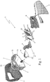
figure 1 shows in an exploded perspective view, with parts removed for clarity, an automobile rear light realized according to the teachings of the present invention; -
figure 2 is a section view of the rear automotive light shown infigure 1 , with parts removed for clarity; whereas -
figures 3 and 4 are two perspective views of a component of the automotive light infigure 1 . - With reference to
figures 1 and2 ,numeral 1 indicates as a whole an automotive light particularly adapted to be fixed to the rear part of the body of a car, motorcycle or the like, i.e. a rear automotive light. - More in detail, in the example shown, the
automotive light 1 is preferably, though not necessarily structured so as to be recessed in the rear part of a car, and comprises: - a substantially basin-shaped, rigid
rear shell 2, which is structured so as to be recessed into a compartment specifically made in the rear part of the vehicle body s; - a front lenticular half-
shell 3, which is provided with at least one portion made of transparent or semitransparent, possibly colored, material and is arranged to close themouth 2a of therear shell 2, preferably, though not necessarily to surface on the outside of the vehicle body s at the same time; and - at least one cup-
shaped reflector body 4, which is arranged inside therear shell 2 with itsmouth 4a facing a corresponding transparent or semitransparent portion of the front lenticular half-shell 3; and - a corresponding
incandescent lamp 5 or the like, which is structured so as to emit light when electricity powered, and is arranged within the cup-shaped body 4, close to the bottom thereof, so as to backlight the transparent or semitransparent portion of the front lenticular half-shell 3 which is aligned with themouth 4a of the cup-shaped body 4. - Obviously, in a different embodiment, the
rear shell 2 may be structured in order to be simply fixed so as to protrude from the rear part of the vehicle body. - In the example shown, in particular, the
rear shell 2 is preferably made of an opaque plastic material by means of an injection molding process; while the front lenticular half-shell 3 is preferably, though not necessarily made of a transparent or semitransparent plastic material, possibly with transparent or semitransparent portions of different color, also in this case preferably by means of an injection molding process. - On the other hand, with regards to the cup-
shaped reflector body 4, theinner surface 4i of the cup-shaped reflector body 4 is preferably metallized or otherwise mirror-finished, so as to reflect the light produced by thelamp 5 towards the transparent or semitransparent portion of the lenticular half-shell 3 which is arranged over themouths 4a of the cup-shaped body 4. - Furthermore, the cup-
shaped reflector body 4 preferably has a substantially parabolic profile, so that the light rays which are reflected by theinner surface 4i of the cup-shaped body 4 towards themouth 4a of the cup-shaped body 4 itself, are locally substantially perpendicular to the portion of the lenticular half-shell 3 which covers themouth 4a of the cup-shaped reflector body 4. - More in detail, in the example shown, the cup-
shaped reflector body 4 is preferably made of an opaque plastic material by means of an injection molding process and itsinner surface 4i is metallized and mirror-finished so as to completely reflect the incident light. - With reference to
figure 2 , thelamp 5 is instead preferably inserted into a through hole made at the bottom of the cup-shaped reflector body 4, so that the glass bulb of the lamp may juts out into the cup-shaped reflector body 4. - With reference to
figures 1 and2 , theautomotive light 1 is additionally provided with at least one set oflight emitting diodes 6, traditionally referred to as LEDs, which are fixed to acommon support base 7 which, in turn, is fixed within therear shell 2 with theLEDs 6 facing a corresponding transparent or semitransparent portion of the front lenticular half-shell 3, so as to allow theLEDs 6 to backlight the same transparent or semitransparent portion of the lenticular half-shell 3. - In the example shown, in particular, the
automotive light 1 is provided with two sets ofLEDs 6, each of which is fixed to acorresponding support base 7 which in turn is fixed within therear shell 2, with theLEDs 6 facing a corresponding transparent or semitransparent portion of the front lenticular half-shell 3 so as to allow theLEDs 6 to backlight the same transparent or semitransparent portion of the lenticular half-shell 3. - Preferably, though not necessarily, the
automotive light 1 additionally comprises a light-guide body 8 made of photoconductive material, which is positioned immediately over theLEDs 6 on thesupport base 7, and is structured so as to collect the light emitted by thevarious LEDs 6, and then convey such a light towards specific areas/zones of the portion of the front lenticular half-shell 3 facing thesupport base 7. - In the example shown, in particular, the guide-
light body 8 is preferably made of a transparent plastic material, such as transparent polycarbonate or transparent polymethyl methacrylate by means of an injection molding process. - With reference to
figures 1 ,2 ,3 and 4 , unlike the current rear automotive lights, theautomotive light 1 further comprises aheat extraction duct 9 that juts out from the bottom of the cup-shaped reflector body 4, and extends upwards into therear shell 2 up to reach an opening 2b made for this purpose at on bottom wall of therear shell 2. - More in detail, the
inlet mouth 9a of theheat extraction duct 9 is arranged immediately above the glass bulb oflamp 5, while theoutlet mouth 9b of theextraction duct 9 is preferably located immediately downstream of the opening 2b made at the bottom of therear shell 2. - In addition to the above description, the passage section of the
heat extraction duct 9 is reduced more or less progressively as the distance from theinlet mouth 9a increases, so as to gradually increase the hot air speed flowing along theheat extraction duct 9. Furthermore, theinner surface 9i of theextraction duct 9 is preferably metallized or otherwise mirror-finished so as to reflect the incident light. - With reference to
figures 1 and2 , the bottom wall of therear shell 2 is instead preferably provided with anadditional air inlet 2c, though which the air can easily/freely penetrate into the closed cavity delimited by therear shell 2 and by the front lenticular half-shell 3, to reach themouth 4a of the cup-shaped reflector body 4. - With reference to
figures 1 ,2 ,3 and 4 , in the example shown, in particular, the cup-shaped reflector body 4 is divided into a lower half-shell 10 and an upper half-shell 11 which are structured so as to be reciprocally coupled and stably fastened by means of a series of snap-locking members, and theheat extraction duct 9 is made in one piece with the upper half-shell 11. - More in detail, in the example shown, the two half-
shells shaped reflector body 4 are both preferably made of an opaque plastic material, by means of an injection molding process, and the face of both, which will form theinner surface 4i of the cup-shaped reflector body 4, is completely coated by a silver paint capable of completely reflecting the incident light. Moreover, this silver paint substantially covers the entireinner surface 9i of theextraction duct 9. - With reference to
figures 1 and2 , theautomotive light 1 is also preferably provided with one or moreprotective screens 13 which are arranged within therear shell 2, between theheat extraction duct 9 and thesupport bases 7, so as to limit the heat transfer by convection and/or radiation to thebases 7 which support theLEDs 6. In the example shown, theprotective screens 13 preferably consist of plates made of metal material and/or of heat insulating material partitions. - The general operation of the
automotive light 1 is easily inferable from the above description and no further explanations are required. - On the other hand, with regards to the operation of the
heat extraction duct 9, experimental tests have indicated that the metallization of theinner surface 4i of the cup-shaped reflectingbody 4 and of theinner surface 9i of theheat extraction duct 9, prevents/limits the cooling of the hot air which surrounds the glass bulb of theincandescent lamp 5 thus significantly increasing the flue effect which is triggered by the heat produced by theincandescent lamp 5 in theheat extraction duct 9. - In other words, the air which reaches the bulb of
lamp 5 throughinlet 4a is heated and then rapidly rises due to the flue effect along theextraction duct 9 without significantly cooling down. The gradually decreasing section of theheat extraction duct 9 allows instead to increase the average speed of the hot air which flows within theextraction duct 9, thus reducing the permanence time of the air within the duct. - Furthermore, the increase of the average speed of the air within the
heat extraction duct 9 results in a very high value of the air flow which crosses the cup-shaped body 4. - This implies that, under stationary conditions, the hot air which leaves the cup-
shaped body 4 by rapidly flowing through theheat extraction duct 9 takes most the heat produced bylamp 5 out of theautomotive light 1. Therefore, the average temperature of the air within therear light 1 is always maintained within values considerably lower than those measurable within a traditional rear light and compatible with the operation of the LEDs. - The advantages deriving from the particular structure of the
automotive light 1 are apparent. By virtue of the presence of theheat extraction duct 9, theLEDs 6 which are inside theautomotive light 1 operate in an environment with significantly lower temperatures, and in which a flow of cold air from the outside continuously circulates, which air flow is capable of effectively cooling theLEDs 6 before reaching theinlet 4a of the cup-shaped body 4. - It is finally apparent that changes and variations can be made to the
automotive light 1 described herein without departing from the scope of the present invention. - For example, in a more advanced embodiment, the base(s) 7 which support
LEDs 6 may be provided with one or more heat sinks made of metal material, which are structured so as to increase the heat transfer from theLEDs 6 to the flow of cold air which enters theautomotive light 1 through theair inlet 2c or other openings/gaps present in therear shell 2.
Claims (11)
- Rear automotive light (1) of the type comprising: a substantially basin-shaped, rear shell (2) which is structured so to be fixed onto the vehicle body; a front lenticular half-shell (3) arranged to close the mouth (2a) of the rear shell (2); at least a cup-shaped reflector body (4) which is arranged inside the rear shell (2) with its own mouth (4a) facing towards a first transparent or semitransparent portion of the front lenticular half-shell (3); and a light source (5) which is structured so to emit light when electricity powered, and is arranged within the rear shell (2), close to the bottom of the latter, so as to be able to backlight said first transparent or semitransparent portion of the front lenticular half-shell (3);
the rear automotive light (1) being characterized in that it also comprises a heat extraction tubular duct (9) that overhangingly protrudes from the bottom of the cup-shaped reflector body (4), and extends upwards inside the rear shell (2) up to reach an opening (2b) made in the back of the rear shell (2). - Rear automotive light according to Claim 1, characterized in that the inlet mouth (9a) of the heat extraction duct (9) is arranged immediately above said light source (5).
- Rear automotive light according to Claim 2, characterized in that the light source (5) is an incandescent lamp or similar (5) and that the inlet mouth (9a) of the heat extraction duct (9) is arranged immediately above the bulb of said incandescent lamp or similar (5).
- Rear automotive light according to any one of the preceding claims, characterized in that the outlet mouth (9b) of the heat extraction duct (9) is arranged immediately downstream of the opening (2b) made in the back of the rear shell (2).
- Rear automotive light according to any one of the preceding claims, characterized in that the passage section of the heat extraction duct (9) decreases as the distance from the inlet mouth (9a) of the heat extraction duct (9) increases.
- Rear automotive light according to any one of the preceding claims, characterized in that the inner surface (9i) of the heat extraction duct (9) is mirror finished so as to reflect incident light.
- Rear automotive light according to any one of the preceding claims, characterized in that the inner surface (4i) of the cup-shaped reflector body (4) is mirror finished so as to reflect incident light.
- Rear automotive light according to any one of the preceding claims, characterized in that the back of rear shell (2) is further provided with an air inlet (2c), through which air can penetrate inside the closed cavity delimited by the rear shell (2) and by the front lenticular half-shell (3).
- Rear automotive light according to any one of the preceding claims, characterized in that the cup-shaped reflector body (4) is subdivided into a lower half-shell (10) and an upper half-shell (11) that are structured for being reciprocally coupled, and in that the heat extraction duct (9) is made in one piece with the upper half-shell (11).
- Rear automotive light according to any one of the preceding claims, characterized by also comprising at least one set of light-emitting diodes (6) which are located on a supporting board (7) that, in turn, is fixed inside the rear shell (2) with the diodes (6) faced towards a corresponding second transparent or semitransparent portion of the front lenticular half-shell (3).
- Rear automotive light according to claim 10, characterized in that it also comprises a light-guide body (8) made of photoconductive material and which is arranged immediately above the light-emitting diodes (6) placed on the support base (7), and is structured so as to collect the light emitted by the various diodes (6) and then channelling this light to specific areas/zones of the second portion of the front lenticular half-shell (3) .
Priority Applications (1)
| Application Number | Priority Date | Filing Date | Title |
|---|---|---|---|
| PL12759197T PL2731826T3 (en) | 2011-07-11 | 2012-07-11 | Rear automotive light |
Applications Claiming Priority (2)
| Application Number | Priority Date | Filing Date | Title |
|---|---|---|---|
| IT000099A ITTV20110099A1 (en) | 2011-07-11 | 2011-07-11 | REAR AUTOMOTIVE HEADLIGHT |
| PCT/IB2012/053548 WO2013008193A1 (en) | 2011-07-11 | 2012-07-11 | Rear automotive light |
Publications (2)
| Publication Number | Publication Date |
|---|---|
| EP2731826A1 EP2731826A1 (en) | 2014-05-21 |
| EP2731826B1 true EP2731826B1 (en) | 2020-04-29 |
Family
ID=44584510
Family Applications (1)
| Application Number | Title | Priority Date | Filing Date |
|---|---|---|---|
| EP12759197.2A Active EP2731826B1 (en) | 2011-07-11 | 2012-07-11 | Rear automotive light |
Country Status (5)
| Country | Link |
|---|---|
| EP (1) | EP2731826B1 (en) |
| ES (1) | ES2802678T3 (en) |
| IT (1) | ITTV20110099A1 (en) |
| PL (1) | PL2731826T3 (en) |
| WO (1) | WO2013008193A1 (en) |
Cited By (2)
| Publication number | Priority date | Publication date | Assignee | Title |
|---|---|---|---|---|
| EP4214440B1 (en) * | 2020-09-18 | 2024-08-21 | Stellantis Auto SAS | Vehicle optical unit with thermal protection |
| WO2025008582A1 (en) * | 2023-07-03 | 2025-01-09 | Stellantis Auto Sas | Rear light for a motor vehicle, comprising a heat dissipating support element |
Family Cites Families (5)
| Publication number | Priority date | Publication date | Assignee | Title |
|---|---|---|---|---|
| JP2001010403A (en) * | 1999-06-30 | 2001-01-16 | Kanto Auto Works Ltd | Car headlamps |
| DE102007059009B4 (en) * | 2007-07-23 | 2014-11-06 | Volkswagen Ag | Enttauungsoptimierung a light |
| JP4997091B2 (en) * | 2007-12-26 | 2012-08-08 | スタンレー電気株式会社 | Vehicle lighting with ventilation holes |
| JP5259254B2 (en) * | 2008-05-23 | 2013-08-07 | トヨタ車体株式会社 | Lamp unit |
| ATE493613T1 (en) * | 2008-07-29 | 2011-01-15 | Hella Kgaa Hueck & Co | HEADLIGHTS FOR VEHICLES |
-
2011
- 2011-07-11 IT IT000099A patent/ITTV20110099A1/en unknown
-
2012
- 2012-07-11 EP EP12759197.2A patent/EP2731826B1/en active Active
- 2012-07-11 PL PL12759197T patent/PL2731826T3/en unknown
- 2012-07-11 ES ES12759197T patent/ES2802678T3/en active Active
- 2012-07-11 WO PCT/IB2012/053548 patent/WO2013008193A1/en not_active Ceased
Non-Patent Citations (1)
| Title |
|---|
| None * |
Cited By (3)
| Publication number | Priority date | Publication date | Assignee | Title |
|---|---|---|---|---|
| EP4214440B1 (en) * | 2020-09-18 | 2024-08-21 | Stellantis Auto SAS | Vehicle optical unit with thermal protection |
| WO2025008582A1 (en) * | 2023-07-03 | 2025-01-09 | Stellantis Auto Sas | Rear light for a motor vehicle, comprising a heat dissipating support element |
| FR3150845A1 (en) * | 2023-07-03 | 2025-01-10 | Psa Automobiles Sa | Rear light for a motor vehicle equipped with a heat-evacuating support element |
Also Published As
| Publication number | Publication date |
|---|---|
| EP2731826A1 (en) | 2014-05-21 |
| ITTV20110099A1 (en) | 2013-01-12 |
| PL2731826T3 (en) | 2020-10-05 |
| ES2802678T3 (en) | 2021-01-20 |
| WO2013008193A1 (en) | 2013-01-17 |
Similar Documents
| Publication | Publication Date | Title |
|---|---|---|
| CN100516644C (en) | Vehicle Interior Lights | |
| CN103635741A (en) | Automotive lighting unit | |
| CN100549516C (en) | Vehicle Interior Lights | |
| CN203718591U (en) | Automobile light integrating daytime running lights and sidelights | |
| CN102252301B (en) | Radiating and defogging device for headlight | |
| TWM464599U (en) | Vehicle LED lamp capable of improving heat dissipation effect | |
| JP2007242291A (en) | Vehicle lighting | |
| CN110553224A (en) | Automobile decoration and car light system that no light source can give out light | |
| CN205842461U (en) | Double light-source system integral LED car lights | |
| EP2731826A1 (en) | Rear automotive light | |
| CN106662303B (en) | Illumination and/or signaling devices generating uniform light on a screen | |
| JP2008204954A (en) | Light module and automotive headlamp | |
| US20140022808A1 (en) | LED Light Module for Vehicle | |
| CN114383109B (en) | Multi-functional multiplexing long and thin run-through lamp and mounting structure thereof | |
| CN206072937U (en) | Vehicular illumination system lamp device | |
| JP2017045506A (en) | Vehicle lighting | |
| CN210740294U (en) | Automobile signal lamp and automobile | |
| CN108626691B (en) | Rear combined lamp capable of realizing uniform light emission through light guide of two-way side light | |
| KR20110121459A (en) | Automotive Headlamps | |
| JP2008021602A (en) | Vehicle lighting | |
| CN220958051U (en) | Front fog lamp with split effect | |
| CN206338741U (en) | Automobile-used headlight and automobile | |
| CN219160196U (en) | Light module and vehicle with same | |
| CN216010703U (en) | headlights for automobiles | |
| CN105378372A (en) | Multifunctional screens for multifunctional optical units of vehicles |
Legal Events
| Date | Code | Title | Description |
|---|---|---|---|
| PUAI | Public reference made under article 153(3) epc to a published international application that has entered the european phase |
Free format text: ORIGINAL CODE: 0009012 |
|
| 17P | Request for examination filed |
Effective date: 20140127 |
|
| AK | Designated contracting states |
Kind code of ref document: A1 Designated state(s): AL AT BE BG CH CY CZ DE DK EE ES FI FR GB GR HR HU IE IS IT LI LT LU LV MC MK MT NL NO PL PT RO RS SE SI SK SM TR |
|
| DAX | Request for extension of the european patent (deleted) | ||
| REG | Reference to a national code |
Ref country code: DE Ref legal event code: R079 Ref document number: 602012069689 Country of ref document: DE Free format text: PREVIOUS MAIN CLASS: B60Q0001260000 Ipc: F21S0045480000 |
|
| RIC1 | Information provided on ipc code assigned before grant |
Ipc: F21S 45/48 20180101AFI20191008BHEP Ipc: B60Q 1/26 20060101ALI20191008BHEP |
|
| GRAP | Despatch of communication of intention to grant a patent |
Free format text: ORIGINAL CODE: EPIDOSNIGR1 |
|
| STAA | Information on the status of an ep patent application or granted ep patent |
Free format text: STATUS: GRANT OF PATENT IS INTENDED |
|
| INTG | Intention to grant announced |
Effective date: 20191115 |
|
| GRAS | Grant fee paid |
Free format text: ORIGINAL CODE: EPIDOSNIGR3 |
|
| GRAA | (expected) grant |
Free format text: ORIGINAL CODE: 0009210 |
|
| STAA | Information on the status of an ep patent application or granted ep patent |
Free format text: STATUS: THE PATENT HAS BEEN GRANTED |
|
| AK | Designated contracting states |
Kind code of ref document: B1 Designated state(s): AL AT BE BG CH CY CZ DE DK EE ES FI FR GB GR HR HU IE IS IT LI LT LU LV MC MK MT NL NO PL PT RO RS SE SI SK SM TR |
|
| REG | Reference to a national code |
Ref country code: GB Ref legal event code: FG4D |
|
| REG | Reference to a national code |
Ref country code: CH Ref legal event code: EP |
|
| REG | Reference to a national code |
Ref country code: DE Ref legal event code: R096 Ref document number: 602012069689 Country of ref document: DE |
|
| REG | Reference to a national code |
Ref country code: AT Ref legal event code: REF Ref document number: 1263870 Country of ref document: AT Kind code of ref document: T Effective date: 20200515 |
|
| REG | Reference to a national code |
Ref country code: IE Ref legal event code: FG4D |
|
| REG | Reference to a national code |
Ref country code: NL Ref legal event code: MP Effective date: 20200429 |
|
| REG | Reference to a national code |
Ref country code: LT Ref legal event code: MG4D |
|
| PG25 | Lapsed in a contracting state [announced via postgrant information from national office to epo] |
Ref country code: SE Free format text: LAPSE BECAUSE OF FAILURE TO SUBMIT A TRANSLATION OF THE DESCRIPTION OR TO PAY THE FEE WITHIN THE PRESCRIBED TIME-LIMIT Effective date: 20200429 Ref country code: NO Free format text: LAPSE BECAUSE OF FAILURE TO SUBMIT A TRANSLATION OF THE DESCRIPTION OR TO PAY THE FEE WITHIN THE PRESCRIBED TIME-LIMIT Effective date: 20200729 Ref country code: LT Free format text: LAPSE BECAUSE OF FAILURE TO SUBMIT A TRANSLATION OF THE DESCRIPTION OR TO PAY THE FEE WITHIN THE PRESCRIBED TIME-LIMIT Effective date: 20200429 Ref country code: PT Free format text: LAPSE BECAUSE OF FAILURE TO SUBMIT A TRANSLATION OF THE DESCRIPTION OR TO PAY THE FEE WITHIN THE PRESCRIBED TIME-LIMIT Effective date: 20200831 Ref country code: GR Free format text: LAPSE BECAUSE OF FAILURE TO SUBMIT A TRANSLATION OF THE DESCRIPTION OR TO PAY THE FEE WITHIN THE PRESCRIBED TIME-LIMIT Effective date: 20200730 Ref country code: IS Free format text: LAPSE BECAUSE OF FAILURE TO SUBMIT A TRANSLATION OF THE DESCRIPTION OR TO PAY THE FEE WITHIN THE PRESCRIBED TIME-LIMIT Effective date: 20200829 Ref country code: FI Free format text: LAPSE BECAUSE OF FAILURE TO SUBMIT A TRANSLATION OF THE DESCRIPTION OR TO PAY THE FEE WITHIN THE PRESCRIBED TIME-LIMIT Effective date: 20200429 |
|
| REG | Reference to a national code |
Ref country code: AT Ref legal event code: MK05 Ref document number: 1263870 Country of ref document: AT Kind code of ref document: T Effective date: 20200429 |
|
| PG25 | Lapsed in a contracting state [announced via postgrant information from national office to epo] |
Ref country code: HR Free format text: LAPSE BECAUSE OF FAILURE TO SUBMIT A TRANSLATION OF THE DESCRIPTION OR TO PAY THE FEE WITHIN THE PRESCRIBED TIME-LIMIT Effective date: 20200429 Ref country code: LV Free format text: LAPSE BECAUSE OF FAILURE TO SUBMIT A TRANSLATION OF THE DESCRIPTION OR TO PAY THE FEE WITHIN THE PRESCRIBED TIME-LIMIT Effective date: 20200429 Ref country code: BG Free format text: LAPSE BECAUSE OF FAILURE TO SUBMIT A TRANSLATION OF THE DESCRIPTION OR TO PAY THE FEE WITHIN THE PRESCRIBED TIME-LIMIT Effective date: 20200729 Ref country code: RS Free format text: LAPSE BECAUSE OF FAILURE TO SUBMIT A TRANSLATION OF THE DESCRIPTION OR TO PAY THE FEE WITHIN THE PRESCRIBED TIME-LIMIT Effective date: 20200429 |
|
| PG25 | Lapsed in a contracting state [announced via postgrant information from national office to epo] |
Ref country code: AL Free format text: LAPSE BECAUSE OF FAILURE TO SUBMIT A TRANSLATION OF THE DESCRIPTION OR TO PAY THE FEE WITHIN THE PRESCRIBED TIME-LIMIT Effective date: 20200429 Ref country code: NL Free format text: LAPSE BECAUSE OF FAILURE TO SUBMIT A TRANSLATION OF THE DESCRIPTION OR TO PAY THE FEE WITHIN THE PRESCRIBED TIME-LIMIT Effective date: 20200429 |
|
| REG | Reference to a national code |
Ref country code: ES Ref legal event code: FG2A Ref document number: 2802678 Country of ref document: ES Kind code of ref document: T3 Effective date: 20210120 |
|
| PG25 | Lapsed in a contracting state [announced via postgrant information from national office to epo] |
Ref country code: RO Free format text: LAPSE BECAUSE OF FAILURE TO SUBMIT A TRANSLATION OF THE DESCRIPTION OR TO PAY THE FEE WITHIN THE PRESCRIBED TIME-LIMIT Effective date: 20200429 Ref country code: EE Free format text: LAPSE BECAUSE OF FAILURE TO SUBMIT A TRANSLATION OF THE DESCRIPTION OR TO PAY THE FEE WITHIN THE PRESCRIBED TIME-LIMIT Effective date: 20200429 Ref country code: AT Free format text: LAPSE BECAUSE OF FAILURE TO SUBMIT A TRANSLATION OF THE DESCRIPTION OR TO PAY THE FEE WITHIN THE PRESCRIBED TIME-LIMIT Effective date: 20200429 Ref country code: SM Free format text: LAPSE BECAUSE OF FAILURE TO SUBMIT A TRANSLATION OF THE DESCRIPTION OR TO PAY THE FEE WITHIN THE PRESCRIBED TIME-LIMIT Effective date: 20200429 Ref country code: DK Free format text: LAPSE BECAUSE OF FAILURE TO SUBMIT A TRANSLATION OF THE DESCRIPTION OR TO PAY THE FEE WITHIN THE PRESCRIBED TIME-LIMIT Effective date: 20200429 |
|
| REG | Reference to a national code |
Ref country code: DE Ref legal event code: R097 Ref document number: 602012069689 Country of ref document: DE |
|
| PG25 | Lapsed in a contracting state [announced via postgrant information from national office to epo] |
Ref country code: SK Free format text: LAPSE BECAUSE OF FAILURE TO SUBMIT A TRANSLATION OF THE DESCRIPTION OR TO PAY THE FEE WITHIN THE PRESCRIBED TIME-LIMIT Effective date: 20200429 Ref country code: MC Free format text: LAPSE BECAUSE OF FAILURE TO SUBMIT A TRANSLATION OF THE DESCRIPTION OR TO PAY THE FEE WITHIN THE PRESCRIBED TIME-LIMIT Effective date: 20200429 |
|
| REG | Reference to a national code |
Ref country code: CH Ref legal event code: PL |
|
| PLBE | No opposition filed within time limit |
Free format text: ORIGINAL CODE: 0009261 |
|
| STAA | Information on the status of an ep patent application or granted ep patent |
Free format text: STATUS: NO OPPOSITION FILED WITHIN TIME LIMIT |
|
| 26N | No opposition filed |
Effective date: 20210201 |
|
| REG | Reference to a national code |
Ref country code: BE Ref legal event code: MM Effective date: 20200731 |
|
| PG25 | Lapsed in a contracting state [announced via postgrant information from national office to epo] |
Ref country code: CH Free format text: LAPSE BECAUSE OF NON-PAYMENT OF DUE FEES Effective date: 20200731 Ref country code: LI Free format text: LAPSE BECAUSE OF NON-PAYMENT OF DUE FEES Effective date: 20200731 Ref country code: LU Free format text: LAPSE BECAUSE OF NON-PAYMENT OF DUE FEES Effective date: 20200711 |
|
| PG25 | Lapsed in a contracting state [announced via postgrant information from national office to epo] |
Ref country code: SI Free format text: LAPSE BECAUSE OF FAILURE TO SUBMIT A TRANSLATION OF THE DESCRIPTION OR TO PAY THE FEE WITHIN THE PRESCRIBED TIME-LIMIT Effective date: 20200429 Ref country code: BE Free format text: LAPSE BECAUSE OF NON-PAYMENT OF DUE FEES Effective date: 20200731 |
|
| REG | Reference to a national code |
Ref country code: DE Ref legal event code: R082 Ref document number: 602012069689 Country of ref document: DE Representative=s name: DREISS PATENTANWAELTE PARTG MBB, DE Ref country code: DE Ref legal event code: R081 Ref document number: 602012069689 Country of ref document: DE Owner name: MARELLI SOSNOWIEC POLAND SP. Z O.O., PL Free format text: FORMER OWNER: AUTOMOTIVE LIGHTING POLSKA SP. Z O.O., SOSNOWIEC, PL |
|
| PG25 | Lapsed in a contracting state [announced via postgrant information from national office to epo] |
Ref country code: IE Free format text: LAPSE BECAUSE OF NON-PAYMENT OF DUE FEES Effective date: 20200711 |
|
| PG25 | Lapsed in a contracting state [announced via postgrant information from national office to epo] |
Ref country code: MT Free format text: LAPSE BECAUSE OF FAILURE TO SUBMIT A TRANSLATION OF THE DESCRIPTION OR TO PAY THE FEE WITHIN THE PRESCRIBED TIME-LIMIT Effective date: 20200429 Ref country code: CY Free format text: LAPSE BECAUSE OF FAILURE TO SUBMIT A TRANSLATION OF THE DESCRIPTION OR TO PAY THE FEE WITHIN THE PRESCRIBED TIME-LIMIT Effective date: 20200429 |
|
| PG25 | Lapsed in a contracting state [announced via postgrant information from national office to epo] |
Ref country code: MK Free format text: LAPSE BECAUSE OF FAILURE TO SUBMIT A TRANSLATION OF THE DESCRIPTION OR TO PAY THE FEE WITHIN THE PRESCRIBED TIME-LIMIT Effective date: 20200429 |
|
| PGFP | Annual fee paid to national office [announced via postgrant information from national office to epo] |
Ref country code: CZ Payment date: 20240625 Year of fee payment: 13 |
|
| PGFP | Annual fee paid to national office [announced via postgrant information from national office to epo] |
Ref country code: PL Payment date: 20240619 Year of fee payment: 13 |
|
| PGFP | Annual fee paid to national office [announced via postgrant information from national office to epo] |
Ref country code: ES Payment date: 20240802 Year of fee payment: 13 |
|
| PGFP | Annual fee paid to national office [announced via postgrant information from national office to epo] |
Ref country code: TR Payment date: 20240702 Year of fee payment: 13 |
|
| PGFP | Annual fee paid to national office [announced via postgrant information from national office to epo] |
Ref country code: FR Payment date: 20250620 Year of fee payment: 14 |
|
| PGFP | Annual fee paid to national office [announced via postgrant information from national office to epo] |
Ref country code: DE Payment date: 20250620 Year of fee payment: 14 |
|
| PGFP | Annual fee paid to national office [announced via postgrant information from national office to epo] |
Ref country code: IT Payment date: 20250619 Year of fee payment: 14 |
|
| PG25 | Lapsed in a contracting state [announced via postgrant information from national office to epo] |
Ref country code: CZ Free format text: LAPSE BECAUSE OF NON-PAYMENT OF DUE FEES Effective date: 20250711 |
|
| PGFP | Annual fee paid to national office [announced via postgrant information from national office to epo] |
Ref country code: GB Payment date: 20260115 Year of fee payment: 14 |