EP2731404A1 - An oven door for a microwave oven or a multifunctional oven with microwave heating function - Google Patents
An oven door for a microwave oven or a multifunctional oven with microwave heating function Download PDFInfo
- Publication number
- EP2731404A1 EP2731404A1 EP12192251.2A EP12192251A EP2731404A1 EP 2731404 A1 EP2731404 A1 EP 2731404A1 EP 12192251 A EP12192251 A EP 12192251A EP 2731404 A1 EP2731404 A1 EP 2731404A1
- Authority
- EP
- European Patent Office
- Prior art keywords
- door
- oven
- glass panel
- columns
- oven door
- Prior art date
- Legal status (The legal status is an assumption and is not a legal conclusion. Google has not performed a legal analysis and makes no representation as to the accuracy of the status listed.)
- Granted
Links
Images



Classifications
-
- H—ELECTRICITY
- H05—ELECTRIC TECHNIQUES NOT OTHERWISE PROVIDED FOR
- H05B—ELECTRIC HEATING; ELECTRIC LIGHT SOURCES NOT OTHERWISE PROVIDED FOR; CIRCUIT ARRANGEMENTS FOR ELECTRIC LIGHT SOURCES, IN GENERAL
- H05B6/00—Heating by electric, magnetic or electromagnetic fields
- H05B6/64—Heating using microwaves
- H05B6/6414—Aspects relating to the door of the microwave heating apparatus
-
- H—ELECTRICITY
- H05—ELECTRIC TECHNIQUES NOT OTHERWISE PROVIDED FOR
- H05B—ELECTRIC HEATING; ELECTRIC LIGHT SOURCES NOT OTHERWISE PROVIDED FOR; CIRCUIT ARRANGEMENTS FOR ELECTRIC LIGHT SOURCES, IN GENERAL
- H05B6/00—Heating by electric, magnetic or electromagnetic fields
- H05B6/64—Heating using microwaves
- H05B6/76—Prevention of microwave leakage, e.g. door sealings
- H05B6/763—Microwave radiation seals for doors
Definitions
- the present invention relates to an oven door for a microwave oven or a multifunctional oven with microwave heating function. Further, the present invention relates to a microwave oven or a multifunctional oven with microwave heating function.
- the oven door requires different features.
- the oven door has to be attached pivoting at a front frame of the oven by hinges.
- the hinges are often arranged inside the oven door and fixed by screws.
- One or two latches in an upper portion of the oven door are parts of a safety interlock system, wherein the other part of said safety interlock system is arranged in the top portion of the front frame.
- the latches are engageable with said parts in the front frame.
- a wave choke system is required in order to prevent a microwave leakage.
- the components of the oven door usually require a lot of fixing elements.
- the object of the present invention is achieved by the oven door according to claim 1.
- the present invention relates to an oven door for a microwave oven or a multifunctional oven with microwave heating function, wherein
- the main idea of the present invention is the direct attachment of the door columns at the inner side of the outer glass panel on the one hand and the attachment of door cover at the door columns on the other hand, wherein the remaining components of the oven door are arranged between the outer glass panel and the door cover.
- This constellation allows a compact structure of the oven door and reduced the number of fixing elements.
- the oven door may be constructed by low complexity.
- the door columns are glued by an adhesive at the inner side of the outer glass panel. This simplifies the production of then oven door.
- the door columns may be attached or attachable by screws at the inner side of the outer glass panel.
- the door columns are made of plastics. This contributes to low costs.
- the door choke system includes at least one metal sheet with a circumferential channel.
- the door choke system includes at least one further metal sheet with a plurality of lamellae along the circumferential channel.
- the door choke system includes a door grid in its central portion.
- the door grid allows shielding of microwave on the one hand and a transparent oven door on the other hand.
- the door choke system is fixed or fixable at the door columns.
- the door choke system is fixed or fixable by screws at the door columns.
- the door cover includes a main wall extending in parallel to the inner glass panel and a circumferential wall perpendicular to said main wall.
- the main wall of the door cover may include a recess in its centre, so the inner glass panel and the door cover form a window with an enclosing frame.
- At least one central glass panel may be arranged or arrangeable between the door columns on the one hand and between the outer glass panel and the door choke system on the other hand.
- the at least one central glass panel is aligned by retaining elements.
- the door column may include at least one latch element engageable with a safety interlock system of the oven.
- the door column and the latch element are formed as a single-piece part.
- the latch element may be made of metal and inserted by moulding into the door column.
- the door column includes a recess for receiving a hinge arm of a door hinge.
- the oven door comprises a door handle fixed or fixable at an outer side of the outer glass panel.
- the present invention relates to a microwave oven or a multifunctional oven with microwave heating function, wherein the oven comprises an oven door mentioned above.
- Novel and inventive features of the present invention are set forth in the appended claims.
- FIG 1 illustrates a perspective view of an oven door 10 for a microwave oven or a multifunctional oven with microwave heating function according to a preferred embodiment of the present invention.
- the oven door 10 comprises an outer glass panel 12, a door handle 14, a door cover 16, an inner glass panel 18, a door choke system 20, a first central glass panel 22, a second central glass panel 24 and two door columns 26.
- the door handle 14 is attached at an outer side of the outer glass panel 12.
- the door cover 16 is attached at an inner side of the outer glass panel 12.
- the door cover 16 includes a main wall 38 and circumferential side walls 40, so that a space is formed between said door cover 16 and the outer glass panel 12.
- the inner glass panel 18, the door choke system 20, the first central glass panel 22, the second central glass panel 24 and the two door columns 26 are arranged inside said space.
- the main wall 38 of the door cover 16 includes a cutout, so that the door cover 16 and the inner glass panel 18 form a window with frame.
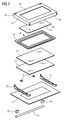
- FIG 2 illustrates an exploded perspective view of the oven door 10 for the microwave oven or multifunctional oven with microwave heating function according to the preferred embodiment of the present invention.
- FIG 2 clarifies the arrangement and positions of the components of the oven door 10.
- the door handle 14 is attached via distance elements 28 at an outer side of the outer glass panel 12.
- the door columns 26 are attached at the inner side of the outer glass panel 12.
- the first central glass panel 22 and the second central glass panel 24 are arranged between the door columns 26.
- Retaining elements 30 are provided for the alignment of the first central glass panel 22 and the second central glass panel 24.
- the inner glass panel 18 is attached at an outer side of the door cover 16.
- the door choke system 20 is arranged between the inner glass panel 18 and the second central glass panel 24.
- FIG 3 illustrates a detailed exploded perspective view of the door column 26 and the outer glass panel 12 of the oven door 10 for the microwave oven or multifunctional oven with microwave heating function according to the preferred embodiment of the present invention.
- the door column 26 is elongated and provided for a vertical arrangement at the inner side of the outer glass panel 12.
- the two door columns 26 are arranged side-by-side and in parallel at the outer glass panel 12.
- the first central glass panel 22 and the second central glass panel 24 are arranged between said two door columns 26.
- the door column 26 includes a latch element 32 at its upper end.
- the latch element 32 is an integrated part of the door column 26.
- the latch element 32 and door column 26 may form a single-piece part.
- the door column 26 with latch element 32 is preferably made of plastics.
- the latch element 32 may be made of metal and inserted by moulding into the door column 26 made of plastics.
- the latch element 32 is engageable with a safety interlock system 42 of the oven. In a closed state of the oven door 10 the latch element 32 is engaged with the safety interlock system 42 arranged in an upper portion behind a front frame of the oven.
- a recess 34 in the lower portion of the door column 26 is provided for receiving a hinge arm of a door hinge.
- the oven door 10 is fixable at the oven by inserting two hinge arms of the door hinge into the door columns 26 of the oven door 10.
- FIG 4 illustrates a further exploded perspective view of the oven door 10 for the microwave oven or multifunctional oven with microwave heating function according to the preferred embodiment of the present invention.
- FIG 4 shows a step during assembling the oven door 10.
- An adhesive 36 is applied on those areas of the inner side of the outer glass panel 12, which are provided for the door columns 26.
- the gluing of the door columns 26 onto the outer glass panel 12 simplifies the assembling of the oven door 10.
- the first central glass panel 22 and the second central glass panel 24 are provided for the intermediate space between the door columns 26.
- the retaining elements 30 allow the alignment of the first central glass panel 22 and the second central glass panel 24.
- the door cover 16 may be fixable at the door columns 26 by screws and/or by a snap-in mechanism.
- the inner glass panel 18 and the door choke system 20 are arranged between the door cover 16 and the second central glass panel 24.
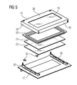
- FIG 5 illustrates another exploded perspective view of the oven door 10 for the microwave oven or multifunctional oven with microwave heating function according to the preferred embodiment of the present invention.
- FIG 5 is similar to FIG 4 , wherein the door columns 26 are glued onto the outer glass panel 12.
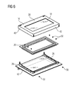
- FIG 6 illustrates a further exploded perspective view of the oven door 10 for the microwave oven or multifunctional oven with microwave heating function according to the preferred embodiment of the present invention.
- FIG 6 is similar to FIG 5 , wherein the first central glass panel 22 and the second central glass panel 24 are already inserted between the door columns 26.
- the door choke system 20 is made of two metal sheets.
- An outer metal sheet includes a circumferential channel for a wave trap.
- An inner metal sheet includes a plurality of lamellae for the wave trap.
- Screws 50 may be provided for fixing the door cover 16 at the door columns 26. Further, the screws 50 may be provided for connecting the inner metal sheet of the door choke system 20 to the outer metal sheet of said door choke system 20. Moreover, the screws 50 may be provided for connecting the door choke system 20 to the door columns 26.
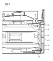
- FIG 7 illustrates a sectional side view of the oven door 10 arranged at the microwave oven or multifunctional oven with microwave heating function according to the preferred embodiment of the present invention.
- the oven door 10 is arranged in front of a front frame 44 of the oven.
- FIG 7 clarifies the arrangement of the door column 26 inside the oven door 10.
- the latch element 32 is an integrated part of the door column 26.
- the latch element 32 is engaged with the safety interlock system 42 arranged behind the upper portion of the front frame 44.
- the door hinge 46 is arranged at the oven below the front frame 44.
- the hinge arm 48 of the door hinge 46 is received by the recess 34 of the door column 26.
- the oven door 10 is easily fixable at the oven by inserting two hinge arms 48 of the door hinge 46 into the door columns 26 of the oven door 10.
Landscapes
- Physics & Mathematics (AREA)
- Electromagnetism (AREA)
- Electric Ovens (AREA)
- Special Wing (AREA)
Abstract
Description
- The present invention relates to an oven door for a microwave oven or a multifunctional oven with microwave heating function. Further, the present invention relates to a microwave oven or a multifunctional oven with microwave heating function.
- In a microwave oven or a multifunctional oven with a microwave heating function the oven door requires different features. The oven door has to be attached pivoting at a front frame of the oven by hinges. The hinges are often arranged inside the oven door and fixed by screws. One or two latches in an upper portion of the oven door are parts of a safety interlock system, wherein the other part of said safety interlock system is arranged in the top portion of the front frame. The latches are engageable with said parts in the front frame. Further, a wave choke system is required in order to prevent a microwave leakage. The components of the oven door usually require a lot of fixing elements.
- It is an object of the present invention to provide an oven door for a microwave oven or a multifunctional oven with microwave heating function, wherein the oven door is constructed by low complexity.
- The object of the present invention is achieved by the oven door according to claim 1.
- The present invention relates to an oven door for a microwave oven or a multifunctional oven with microwave heating function, wherein
- the oven door comprises an outer glass panel,
- the oven door comprises at least two door columns directly attached or attachable at an inner side of the outer glass panel,
- the oven door comprises a door cover arranged or arrangeable at an inner side of the outer glass panel and attached or attachable at the door columns,
- the oven door comprises a door choke system arranged or arrangeable between the door cover and the outer glass panel, and
- the oven door comprises an inner glass panel arranged or arrangeable between the door cover and the door choke system.
- The main idea of the present invention is the direct attachment of the door columns at the inner side of the outer glass panel on the one hand and the attachment of door cover at the door columns on the other hand, wherein the remaining components of the oven door are arranged between the outer glass panel and the door cover. This constellation allows a compact structure of the oven door and reduced the number of fixing elements. Thus, the oven door may be constructed by low complexity.
- According to a special embodiment of the present invention the door columns are glued by an adhesive at the inner side of the outer glass panel. This simplifies the production of then oven door.
- Alternatively, the door columns may be attached or attachable by screws at the inner side of the outer glass panel.
- In particular, the door columns are made of plastics. This contributes to low costs.
- For example, the door choke system includes at least one metal sheet with a circumferential channel.
- Preferably, the door choke system includes at least one further metal sheet with a plurality of lamellae along the circumferential channel.
- In particular, the door choke system includes a door grid in its central portion. The door grid allows shielding of microwave on the one hand and a transparent oven door on the other hand.
- Further, the door choke system is fixed or fixable at the door columns. For example, the door choke system is fixed or fixable by screws at the door columns.
- According to a preferred embodiment of the present invention the door cover includes a main wall extending in parallel to the inner glass panel and a circumferential wall perpendicular to said main wall.
- In this case, the main wall of the door cover may include a recess in its centre, so the inner glass panel and the door cover form a window with an enclosing frame.
- Moreover, at least one central glass panel may be arranged or arrangeable between the door columns on the one hand and between the outer glass panel and the door choke system on the other hand.
- Preferably, the at least one central glass panel is aligned by retaining elements.
- Further, the door column may include at least one latch element engageable with a safety interlock system of the oven.
- For example, the door column and the latch element are formed as a single-piece part.
- Alternatively, the latch element may be made of metal and inserted by moulding into the door column.
- In particular, the door column includes a recess for receiving a hinge arm of a door hinge.
- Preferably, the oven door comprises a door handle fixed or fixable at an outer side of the outer glass panel.
- Further, the present invention relates to a microwave oven or a multifunctional oven with microwave heating function, wherein the oven comprises an oven door mentioned above. Novel and inventive features of the present invention are set forth in the appended claims.
- The present invention will be described in further detail with reference to the drawings, in which
- FIG 1
- illustrates a perspective view of an oven door for a microwave oven or a multifunctional oven with microwave heating function according to a preferred embodiment of the present invention,
- FIG 2
- illustrates an exploded perspective view of the oven door for the microwave oven or multifunctional oven with microwave heating function according to the preferred embodiment of the present invention,
- FIG 3
- illustrates a detailed exploded perspective view of a door column and an outer glass panel of the oven door for the microwave oven or multifunctional oven with microwave heating function according to the preferred embodiment of the present invention,
- FIG 4
- illustrates a further exploded perspective view of the oven door for the microwave oven or multifunctional oven with microwave heating function according to the preferred embodiment of the present invention,
- FIG 5
- illustrates another exploded perspective view of the oven door for the microwave oven or multifunctional oven with microwave heating function according to the preferred embodiment of the present invention,
- FIG 6
- illustrates a further exploded perspective view of the oven door for the microwave oven or multifunctional oven with microwave heating function according to the preferred embodiment of the present invention, and
- FIG 7
- illustrates a sectional side view of the oven door arranged at the microwave oven or multifunctional oven with microwave heating function according to the preferred embodiment of the present invention.
-
FIG 1 illustrates a perspective view of anoven door 10 for a microwave oven or a multifunctional oven with microwave heating function according to a preferred embodiment of the present invention. - The
oven door 10 comprises anouter glass panel 12, adoor handle 14, adoor cover 16, aninner glass panel 18, adoor choke system 20, a firstcentral glass panel 22, a secondcentral glass panel 24 and twodoor columns 26. - The
door handle 14 is attached at an outer side of theouter glass panel 12. Thedoor cover 16 is attached at an inner side of theouter glass panel 12. Thedoor cover 16 includes amain wall 38 andcircumferential side walls 40, so that a space is formed between saiddoor cover 16 and theouter glass panel 12. Theinner glass panel 18, thedoor choke system 20, the firstcentral glass panel 22, the secondcentral glass panel 24 and the twodoor columns 26 are arranged inside said space. Themain wall 38 of thedoor cover 16 includes a cutout, so that thedoor cover 16 and theinner glass panel 18 form a window with frame. -
FIG 2 illustrates an exploded perspective view of theoven door 10 for the microwave oven or multifunctional oven with microwave heating function according to the preferred embodiment of the present invention.FIG 2 clarifies the arrangement and positions of the components of theoven door 10. - The
door handle 14 is attached viadistance elements 28 at an outer side of theouter glass panel 12. Thedoor columns 26 are attached at the inner side of theouter glass panel 12. The firstcentral glass panel 22 and the secondcentral glass panel 24 are arranged between thedoor columns 26. Retainingelements 30 are provided for the alignment of the firstcentral glass panel 22 and the secondcentral glass panel 24. Theinner glass panel 18 is attached at an outer side of thedoor cover 16. Thedoor choke system 20 is arranged between theinner glass panel 18 and the secondcentral glass panel 24. -
FIG 3 illustrates a detailed exploded perspective view of thedoor column 26 and theouter glass panel 12 of theoven door 10 for the microwave oven or multifunctional oven with microwave heating function according to the preferred embodiment of the present invention. - The
door column 26 is elongated and provided for a vertical arrangement at the inner side of theouter glass panel 12. The twodoor columns 26 are arranged side-by-side and in parallel at theouter glass panel 12. The firstcentral glass panel 22 and the secondcentral glass panel 24 are arranged between said twodoor columns 26. - The
door column 26 includes alatch element 32 at its upper end. Thelatch element 32 is an integrated part of thedoor column 26. For example, thelatch element 32 anddoor column 26 may form a single-piece part. In this case, thedoor column 26 withlatch element 32 is preferably made of plastics. Further, thelatch element 32 may be made of metal and inserted by moulding into thedoor column 26 made of plastics. Thelatch element 32 is engageable with asafety interlock system 42 of the oven. In a closed state of theoven door 10 thelatch element 32 is engaged with thesafety interlock system 42 arranged in an upper portion behind a front frame of the oven. - A
recess 34 in the lower portion of thedoor column 26 is provided for receiving a hinge arm of a door hinge. Theoven door 10 is fixable at the oven by inserting two hinge arms of the door hinge into thedoor columns 26 of theoven door 10. -
FIG 4 illustrates a further exploded perspective view of theoven door 10 for the microwave oven or multifunctional oven with microwave heating function according to the preferred embodiment of the present invention.FIG 4 shows a step during assembling theoven door 10. - An adhesive 36 is applied on those areas of the inner side of the
outer glass panel 12, which are provided for thedoor columns 26. The gluing of thedoor columns 26 onto theouter glass panel 12 simplifies the assembling of theoven door 10. The firstcentral glass panel 22 and the secondcentral glass panel 24 are provided for the intermediate space between thedoor columns 26. The retainingelements 30 allow the alignment of the firstcentral glass panel 22 and the secondcentral glass panel 24. - The door cover 16 may be fixable at the
door columns 26 by screws and/or by a snap-in mechanism. Theinner glass panel 18 and thedoor choke system 20 are arranged between thedoor cover 16 and the secondcentral glass panel 24. -
FIG 5 illustrates another exploded perspective view of theoven door 10 for the microwave oven or multifunctional oven with microwave heating function according to the preferred embodiment of the present invention.FIG 5 is similar toFIG 4 , wherein thedoor columns 26 are glued onto theouter glass panel 12. -
FIG 6 illustrates a further exploded perspective view of theoven door 10 for the microwave oven or multifunctional oven with microwave heating function according to the preferred embodiment of the present invention.FIG 6 is similar toFIG 5 , wherein the firstcentral glass panel 22 and the secondcentral glass panel 24 are already inserted between thedoor columns 26. - In this example, the
door choke system 20 is made of two metal sheets. An outer metal sheet includes a circumferential channel for a wave trap. An inner metal sheet includes a plurality of lamellae for the wave trap. -
Screws 50 may be provided for fixing thedoor cover 16 at thedoor columns 26. Further, thescrews 50 may be provided for connecting the inner metal sheet of thedoor choke system 20 to the outer metal sheet of saiddoor choke system 20. Moreover, thescrews 50 may be provided for connecting thedoor choke system 20 to thedoor columns 26. -
FIG 7 illustrates a sectional side view of theoven door 10 arranged at the microwave oven or multifunctional oven with microwave heating function according to the preferred embodiment of the present invention. - The
oven door 10 is arranged in front of afront frame 44 of the oven.FIG 7 clarifies the arrangement of thedoor column 26 inside theoven door 10. Thelatch element 32 is an integrated part of thedoor column 26. Thelatch element 32 is engaged with thesafety interlock system 42 arranged behind the upper portion of thefront frame 44. - The door hinge 46 is arranged at the oven below the
front frame 44. Thehinge arm 48 of thedoor hinge 46 is received by therecess 34 of thedoor column 26. Theoven door 10 is easily fixable at the oven by inserting twohinge arms 48 of thedoor hinge 46 into thedoor columns 26 of theoven door 10. - Although an illustrative embodiment of the present invention has been described herein with reference to the accompanying drawings, it is to be understood that the present invention is not limited to that precise embodiment, and that various other changes and modifications may be affected therein by one skilled in the art without departing from the scope or spirit of the invention. All such changes and modifications are intended to be included within the scope of the invention as defined by the appended claims.
-
- 10
- oven door
- 12
- outer glass panel
- 14
- door handle
- 16
- door cover
- 18
- inner glass panel
- 20
- door choke system
- 22
- first central glass panel
- 24
- second central glass panel
- 26
- door column
- 28
- distance element
- 30
- retaining element
- 32
- latch element
- 34
- recess
- 36
- adhesive
- 38
- main wall
- 40
- circumferential wall
- 42
- safety interlock system
- 44
- front frame
- 46
- door hinge
- 48
- hinge arm
- 50
- screw
Claims (15)
- An oven door (10) for a microwave oven or a multifunctional oven with microwave heating function, wherein- the oven door (10) comprises an outer glass panel (12),- the oven door (10) comprises at least two door columns (26) directly attached or attachable at an inner side of the outer glass panel (12),- the oven door (10) comprises a door cover (16) arranged or arrangeable at an inner side of the outer glass panel (12) and attached or attachable at the door columns (26),- the oven door (10) comprises a door choke system (20) arranged or arrangeable between the door cover (16) and the outer glass panel (12), and- the oven door (10) comprises an inner glass panel (18) arranged or arrangeable between the door cover (16) and the door choke system (20).
- The oven door according to claim 1,
characterized in that
the door columns (26) are glued by an adhesive (36) at the inner side of the outer glass panel (12) or in that the door columns (26) are attached or attachable by screws at the inner side of the outer glass panel (12). - The oven door according to any one of the preceding claims,
characterized in that
the door columns (26) are made of plastics. - The oven door according to any one of the preceding claims,
characterized in that
the door choke system (20) includes at least one metal sheet with a circumferential channel. - The oven door according to claim 4,
characterized in that
the door choke system (20) includes at least one further metal sheet with a plurality of lamellae along the circumferential channel. - The oven door according to claims 4 or 5,
characterized in that
the door choke system (20) includes a door grid in its central portion. - The oven door according to any one of the preceding claims,
characterized in that
the door choke system (20) is fixed or fixable, in particular by screws (50), at the door columns (26). - The oven door according to any one of the preceding claims,
characterized in that
the door cover (16) includes a main wall (38) extending in parallel to the inner glass panel (18) and a circumferential wall (40) perpendicular to said main wall (38). - The oven door according to claim 8,
characterized in that
the main wall (38) of the door cover (16) includes a recess in its centre, so the inner glass panel (18) and the door cover (16) form a window with an enclosing frame. - The oven door according to any one of the preceding claims,
characterized in that
at least one central glass panel (22, 24) is arranged or arrangeable between the door columns (26) on the one hand and between the outer glass panel (12) and the door choke system (20) on the other hand. - The oven door according to claim 10,
characterized in that
the at least one central glass panel (22, 24) is aligned by retaining elements (30). - The oven door according to any one of the preceding claims,
characterized in that
the door column (26) includes at least one latch element (32) engageable with a safety interlock system (42) of the oven. - The oven door according to claim 14,
characterized in that
the door column (26) and the latch element (32) are formed as a single-piece part or in that the latch element (32) is made of metal and inserted by moulding into the door column (26). - The oven door according to any one of the preceding claims,
characterized in that
the door column (26) includes a recess (34) for receiving a hinge arm (48) of a door hinge (46). - A microwave oven or a multifunctional oven with microwave heating function,
characterized in that
the oven comprises an oven door (10) according to any one of the claims 1 to 14.
Priority Applications (5)
| Application Number | Priority Date | Filing Date | Title |
|---|---|---|---|
| EP12192251.2A EP2731404B1 (en) | 2012-11-12 | 2012-11-12 | An oven door for a microwave oven or a multifunctional oven with microwave heating function |
| CN201380051808.6A CN104685967A (en) | 2012-11-12 | 2013-10-31 | Oven door for microwave oven or multifunctional oven with microwave heating function |
| AU2013343759A AU2013343759B2 (en) | 2012-11-12 | 2013-10-31 | An oven door for a microwave oven or a multifunctional oven with microwave heating function |
| US14/432,545 US9907122B2 (en) | 2012-11-12 | 2013-10-31 | Oven door for a microwave oven or a multifunctional oven with microwave heating function |
| PCT/EP2013/072782 WO2014072218A1 (en) | 2012-11-12 | 2013-10-31 | An oven door for a microwave oven or a multifunctional oven with microwave heating function |
Applications Claiming Priority (1)
| Application Number | Priority Date | Filing Date | Title |
|---|---|---|---|
| EP12192251.2A EP2731404B1 (en) | 2012-11-12 | 2012-11-12 | An oven door for a microwave oven or a multifunctional oven with microwave heating function |
Publications (2)
| Publication Number | Publication Date |
|---|---|
| EP2731404A1 true EP2731404A1 (en) | 2014-05-14 |
| EP2731404B1 EP2731404B1 (en) | 2020-04-08 |
Family
ID=47325849
Family Applications (1)
| Application Number | Title | Priority Date | Filing Date |
|---|---|---|---|
| EP12192251.2A Active EP2731404B1 (en) | 2012-11-12 | 2012-11-12 | An oven door for a microwave oven or a multifunctional oven with microwave heating function |
Country Status (5)
| Country | Link |
|---|---|
| US (1) | US9907122B2 (en) |
| EP (1) | EP2731404B1 (en) |
| CN (1) | CN104685967A (en) |
| AU (1) | AU2013343759B2 (en) |
| WO (1) | WO2014072218A1 (en) |
Cited By (3)
| Publication number | Priority date | Publication date | Assignee | Title |
|---|---|---|---|---|
| EP3358908A1 (en) | 2017-02-01 | 2018-08-08 | Gorenje Gospodinjski aparati d.d. | Door of a multifunctional oven and/or a microwave oven |
| EP3426002A1 (en) * | 2017-07-07 | 2019-01-09 | LG Electronics Inc. | Door and cooking appliance with the same |
| EP4543143A1 (en) | 2023-10-20 | 2025-04-23 | Electrolux Appliances Aktiebolag | Oven door for a domestic oven having a microwave heating function |
Families Citing this family (8)
| Publication number | Priority date | Publication date | Assignee | Title |
|---|---|---|---|---|
| EP2807902B1 (en) | 2012-01-23 | 2020-08-19 | CONNORS, Robert W. | Compact microwave oven |
| EP2868981B1 (en) * | 2013-10-31 | 2017-10-25 | Electrolux Appliances Aktiebolag | A door for a domestic appliance |
| EP3057381B1 (en) * | 2015-02-11 | 2017-08-23 | Electrolux Appliances Aktiebolag | An oven door for a microwave oven |
| ITUB20152351A1 (en) * | 2015-07-21 | 2017-01-21 | Tecno Spa | OVEN DOOR |
| KR102458437B1 (en) * | 2015-08-04 | 2022-10-26 | 삼성전자주식회사 | Oven |
| USD827369S1 (en) * | 2016-06-14 | 2018-09-04 | Lg Electronics Inc. | Microwave oven |
| US10710313B2 (en) * | 2016-11-07 | 2020-07-14 | Iftikhar Ahmad | Near-field microwave heating system and method |
| US10782028B2 (en) * | 2017-11-15 | 2020-09-22 | Bsh Home Appliances Corporation | Glass on outside of range door |
Citations (8)
| Publication number | Priority date | Publication date | Assignee | Title |
|---|---|---|---|---|
| DE8905292U1 (en) * | 1989-04-26 | 1989-06-29 | Siemens Ag, 1000 Berlin Und 8000 Muenchen | Plastic inner lining for microwave oven, suitable for heating aggressive chemicals |
| EP0687867A1 (en) * | 1994-06-14 | 1995-12-20 | New World (Group) Limited | Cooking appliances |
| EP0811806A1 (en) * | 1996-06-05 | 1997-12-10 | AEG Hausgeräte GmbH | Door for closing the muffle of a baking oven |
| US20040149748A1 (en) * | 2002-10-29 | 2004-08-05 | Kurt Leutner | Microwave unit door with viewing window |
| EP1555486A2 (en) * | 2003-12-22 | 2005-07-20 | Electrolux Home Products N.V. | Oven door |
| US20050205564A1 (en) * | 2004-01-23 | 2005-09-22 | Electrolux Schwanden Ag | Broiling oven |
| EP1850072A2 (en) * | 2006-04-24 | 2007-10-31 | LG Electronics Inc. | Oven door |
| EP2291056A1 (en) * | 2009-08-29 | 2011-03-02 | Electrolux Home Products Corporation N.V. | Snap arm unit for a door interlocking device |
Family Cites Families (2)
| Publication number | Priority date | Publication date | Assignee | Title |
|---|---|---|---|---|
| US3731035A (en) * | 1971-11-15 | 1973-05-01 | Litton Systems Inc | Microwave oven door |
| KR100774505B1 (en) * | 2006-05-29 | 2007-11-08 | 엘지전자 주식회사 | Door Assemblies for Combined Ranges |
-
2012
- 2012-11-12 EP EP12192251.2A patent/EP2731404B1/en active Active
-
2013
- 2013-10-31 WO PCT/EP2013/072782 patent/WO2014072218A1/en not_active Ceased
- 2013-10-31 CN CN201380051808.6A patent/CN104685967A/en active Pending
- 2013-10-31 AU AU2013343759A patent/AU2013343759B2/en active Active
- 2013-10-31 US US14/432,545 patent/US9907122B2/en active Active
Patent Citations (8)
| Publication number | Priority date | Publication date | Assignee | Title |
|---|---|---|---|---|
| DE8905292U1 (en) * | 1989-04-26 | 1989-06-29 | Siemens Ag, 1000 Berlin Und 8000 Muenchen | Plastic inner lining for microwave oven, suitable for heating aggressive chemicals |
| EP0687867A1 (en) * | 1994-06-14 | 1995-12-20 | New World (Group) Limited | Cooking appliances |
| EP0811806A1 (en) * | 1996-06-05 | 1997-12-10 | AEG Hausgeräte GmbH | Door for closing the muffle of a baking oven |
| US20040149748A1 (en) * | 2002-10-29 | 2004-08-05 | Kurt Leutner | Microwave unit door with viewing window |
| EP1555486A2 (en) * | 2003-12-22 | 2005-07-20 | Electrolux Home Products N.V. | Oven door |
| US20050205564A1 (en) * | 2004-01-23 | 2005-09-22 | Electrolux Schwanden Ag | Broiling oven |
| EP1850072A2 (en) * | 2006-04-24 | 2007-10-31 | LG Electronics Inc. | Oven door |
| EP2291056A1 (en) * | 2009-08-29 | 2011-03-02 | Electrolux Home Products Corporation N.V. | Snap arm unit for a door interlocking device |
Cited By (5)
| Publication number | Priority date | Publication date | Assignee | Title |
|---|---|---|---|---|
| EP3358908A1 (en) | 2017-02-01 | 2018-08-08 | Gorenje Gospodinjski aparati d.d. | Door of a multifunctional oven and/or a microwave oven |
| EP3426002A1 (en) * | 2017-07-07 | 2019-01-09 | LG Electronics Inc. | Door and cooking appliance with the same |
| US10805993B2 (en) | 2017-07-07 | 2020-10-13 | Lg Electronics Inc. | Door and cooking appliance with the same |
| EP4543143A1 (en) | 2023-10-20 | 2025-04-23 | Electrolux Appliances Aktiebolag | Oven door for a domestic oven having a microwave heating function |
| WO2025082738A1 (en) | 2023-10-20 | 2025-04-24 | Electrolux Appliances Aktiebolag | Oven door for a domestic oven having a microwave heating function |
Also Published As
| Publication number | Publication date |
|---|---|
| WO2014072218A1 (en) | 2014-05-15 |
| AU2013343759A1 (en) | 2015-04-02 |
| US9907122B2 (en) | 2018-02-27 |
| US20150245422A1 (en) | 2015-08-27 |
| AU2013343759B2 (en) | 2017-04-13 |
| CN104685967A (en) | 2015-06-03 |
| EP2731404B1 (en) | 2020-04-08 |
Similar Documents
| Publication | Publication Date | Title |
|---|---|---|
| US9907122B2 (en) | Oven door for a microwave oven or a multifunctional oven with microwave heating function | |
| US9913323B2 (en) | Door for a microwave appliance | |
| AU2011252415B2 (en) | A door for a domestic appliance | |
| EP2868981B1 (en) | A door for a domestic appliance | |
| US20170159942A1 (en) | Glass package and framework for an oven door of a cooking oven | |
| EP2110607A1 (en) | A cooking hob with one-piece fastening elements and a one-piece fastening element for a cooking hob | |
| EP2012064A1 (en) | A cooking oven door with a frame door and a door panel | |
| US20220074599A1 (en) | A door for a household appliance | |
| EP3709780B1 (en) | Control panel for an apparatus, in particular for a domestic appliance, and a method for assembling said control panel | |
| EP2314931A1 (en) | A bearing structure for a casing of a domestic appliance | |
| KR20180055937A (en) | Handle for Opening and Closing Sliding Door | |
| US20190125078A1 (en) | Mounting device and domestic appliance | |
| EP2469179A2 (en) | Household appliance door | |
| EP2636956B1 (en) | An oven door for a cooking oven and a method for preparing an oven door for a cooking oven | |
| EP2372059B1 (en) | A door hinge device for an oven cavity of a cooking oven | |
| EP2011399A1 (en) | An oven door with a door frame and a door panel | |
| EP3104084A1 (en) | Domestic oven | |
| EP3324127A1 (en) | Domestic appliance including a casing | |
| EP2397773B1 (en) | A cooking hob with one or more heating systems | |
| EP2390584B1 (en) | Oven cabinet | |
| EP2580987B1 (en) | A drawer including a drawer panel and a drawer box | |
| US20130000626A1 (en) | Oven door with a plastic door column and a method for assembling said plastic door column | |
| GB2410766A (en) | Hinge mounting unit for door | |
| EP2390583B1 (en) | A casing for a domestic appliance and a method for assembling a casing | |
| JP2014034807A (en) | Window unit |
Legal Events
| Date | Code | Title | Description |
|---|---|---|---|
| PUAI | Public reference made under article 153(3) epc to a published international application that has entered the european phase |
Free format text: ORIGINAL CODE: 0009012 |
|
| 17P | Request for examination filed |
Effective date: 20121112 |
|
| AK | Designated contracting states |
Kind code of ref document: A1 Designated state(s): AL AT BE BG CH CY CZ DE DK EE ES FI FR GB GR HR HU IE IS IT LI LT LU LV MC MK MT NL NO PL PT RO RS SE SI SK SM TR |
|
| AX | Request for extension of the european patent |
Extension state: BA ME |
|
| R17P | Request for examination filed (corrected) |
Effective date: 20140627 |
|
| RBV | Designated contracting states (corrected) |
Designated state(s): AL AT BE BG CH CY CZ DE DK EE ES FI FR GB GR HR HU IE IS IT LI LT LU LV MC MK MT NL NO PL PT RO RS SE SI SK SM TR |
|
| STAA | Information on the status of an ep patent application or granted ep patent |
Free format text: STATUS: EXAMINATION IS IN PROGRESS |
|
| 17Q | First examination report despatched |
Effective date: 20171211 |
|
| GRAP | Despatch of communication of intention to grant a patent |
Free format text: ORIGINAL CODE: EPIDOSNIGR1 |
|
| STAA | Information on the status of an ep patent application or granted ep patent |
Free format text: STATUS: GRANT OF PATENT IS INTENDED |
|
| INTG | Intention to grant announced |
Effective date: 20191031 |
|
| GRAS | Grant fee paid |
Free format text: ORIGINAL CODE: EPIDOSNIGR3 |
|
| GRAA | (expected) grant |
Free format text: ORIGINAL CODE: 0009210 |
|
| STAA | Information on the status of an ep patent application or granted ep patent |
Free format text: STATUS: THE PATENT HAS BEEN GRANTED |
|
| AK | Designated contracting states |
Kind code of ref document: B1 Designated state(s): AL AT BE BG CH CY CZ DE DK EE ES FI FR GB GR HR HU IE IS IT LI LT LU LV MC MK MT NL NO PL PT RO RS SE SI SK SM TR |
|
| REG | Reference to a national code |
Ref country code: GB Ref legal event code: FG4D |
|
| REG | Reference to a national code |
Ref country code: CH Ref legal event code: EP Ref country code: AT Ref legal event code: REF Ref document number: 1256148 Country of ref document: AT Kind code of ref document: T Effective date: 20200415 |
|
| REG | Reference to a national code |
Ref country code: DE Ref legal event code: R096 Ref document number: 602012069073 Country of ref document: DE |
|
| REG | Reference to a national code |
Ref country code: IE Ref legal event code: FG4D |
|
| REG | Reference to a national code |
Ref country code: NL Ref legal event code: MP Effective date: 20200408 |
|
| REG | Reference to a national code |
Ref country code: LT Ref legal event code: MG4D |
|
| PG25 | Lapsed in a contracting state [announced via postgrant information from national office to epo] |
Ref country code: PT Free format text: LAPSE BECAUSE OF FAILURE TO SUBMIT A TRANSLATION OF THE DESCRIPTION OR TO PAY THE FEE WITHIN THE PRESCRIBED TIME-LIMIT Effective date: 20200817 Ref country code: LT Free format text: LAPSE BECAUSE OF FAILURE TO SUBMIT A TRANSLATION OF THE DESCRIPTION OR TO PAY THE FEE WITHIN THE PRESCRIBED TIME-LIMIT Effective date: 20200408 Ref country code: NL Free format text: LAPSE BECAUSE OF FAILURE TO SUBMIT A TRANSLATION OF THE DESCRIPTION OR TO PAY THE FEE WITHIN THE PRESCRIBED TIME-LIMIT Effective date: 20200408 Ref country code: NO Free format text: LAPSE BECAUSE OF FAILURE TO SUBMIT A TRANSLATION OF THE DESCRIPTION OR TO PAY THE FEE WITHIN THE PRESCRIBED TIME-LIMIT Effective date: 20200708 Ref country code: GR Free format text: LAPSE BECAUSE OF FAILURE TO SUBMIT A TRANSLATION OF THE DESCRIPTION OR TO PAY THE FEE WITHIN THE PRESCRIBED TIME-LIMIT Effective date: 20200709 Ref country code: SE Free format text: LAPSE BECAUSE OF FAILURE TO SUBMIT A TRANSLATION OF THE DESCRIPTION OR TO PAY THE FEE WITHIN THE PRESCRIBED TIME-LIMIT Effective date: 20200408 Ref country code: IS Free format text: LAPSE BECAUSE OF FAILURE TO SUBMIT A TRANSLATION OF THE DESCRIPTION OR TO PAY THE FEE WITHIN THE PRESCRIBED TIME-LIMIT Effective date: 20200808 Ref country code: FI Free format text: LAPSE BECAUSE OF FAILURE TO SUBMIT A TRANSLATION OF THE DESCRIPTION OR TO PAY THE FEE WITHIN THE PRESCRIBED TIME-LIMIT Effective date: 20200408 |
|
| REG | Reference to a national code |
Ref country code: AT Ref legal event code: MK05 Ref document number: 1256148 Country of ref document: AT Kind code of ref document: T Effective date: 20200408 |
|
| PG25 | Lapsed in a contracting state [announced via postgrant information from national office to epo] |
Ref country code: RS Free format text: LAPSE BECAUSE OF FAILURE TO SUBMIT A TRANSLATION OF THE DESCRIPTION OR TO PAY THE FEE WITHIN THE PRESCRIBED TIME-LIMIT Effective date: 20200408 Ref country code: HR Free format text: LAPSE BECAUSE OF FAILURE TO SUBMIT A TRANSLATION OF THE DESCRIPTION OR TO PAY THE FEE WITHIN THE PRESCRIBED TIME-LIMIT Effective date: 20200408 Ref country code: LV Free format text: LAPSE BECAUSE OF FAILURE TO SUBMIT A TRANSLATION OF THE DESCRIPTION OR TO PAY THE FEE WITHIN THE PRESCRIBED TIME-LIMIT Effective date: 20200408 Ref country code: BG Free format text: LAPSE BECAUSE OF FAILURE TO SUBMIT A TRANSLATION OF THE DESCRIPTION OR TO PAY THE FEE WITHIN THE PRESCRIBED TIME-LIMIT Effective date: 20200708 |
|
| PG25 | Lapsed in a contracting state [announced via postgrant information from national office to epo] |
Ref country code: AL Free format text: LAPSE BECAUSE OF FAILURE TO SUBMIT A TRANSLATION OF THE DESCRIPTION OR TO PAY THE FEE WITHIN THE PRESCRIBED TIME-LIMIT Effective date: 20200408 |
|
| REG | Reference to a national code |
Ref country code: DE Ref legal event code: R097 Ref document number: 602012069073 Country of ref document: DE |
|
| PG25 | Lapsed in a contracting state [announced via postgrant information from national office to epo] |
Ref country code: SM Free format text: LAPSE BECAUSE OF FAILURE TO SUBMIT A TRANSLATION OF THE DESCRIPTION OR TO PAY THE FEE WITHIN THE PRESCRIBED TIME-LIMIT Effective date: 20200408 Ref country code: EE Free format text: LAPSE BECAUSE OF FAILURE TO SUBMIT A TRANSLATION OF THE DESCRIPTION OR TO PAY THE FEE WITHIN THE PRESCRIBED TIME-LIMIT Effective date: 20200408 Ref country code: RO Free format text: LAPSE BECAUSE OF FAILURE TO SUBMIT A TRANSLATION OF THE DESCRIPTION OR TO PAY THE FEE WITHIN THE PRESCRIBED TIME-LIMIT Effective date: 20200408 Ref country code: CZ Free format text: LAPSE BECAUSE OF FAILURE TO SUBMIT A TRANSLATION OF THE DESCRIPTION OR TO PAY THE FEE WITHIN THE PRESCRIBED TIME-LIMIT Effective date: 20200408 Ref country code: ES Free format text: LAPSE BECAUSE OF FAILURE TO SUBMIT A TRANSLATION OF THE DESCRIPTION OR TO PAY THE FEE WITHIN THE PRESCRIBED TIME-LIMIT Effective date: 20200408 Ref country code: AT Free format text: LAPSE BECAUSE OF FAILURE TO SUBMIT A TRANSLATION OF THE DESCRIPTION OR TO PAY THE FEE WITHIN THE PRESCRIBED TIME-LIMIT Effective date: 20200408 Ref country code: DK Free format text: LAPSE BECAUSE OF FAILURE TO SUBMIT A TRANSLATION OF THE DESCRIPTION OR TO PAY THE FEE WITHIN THE PRESCRIBED TIME-LIMIT Effective date: 20200408 |
|
| PLBE | No opposition filed within time limit |
Free format text: ORIGINAL CODE: 0009261 |
|
| STAA | Information on the status of an ep patent application or granted ep patent |
Free format text: STATUS: NO OPPOSITION FILED WITHIN TIME LIMIT |
|
| PG25 | Lapsed in a contracting state [announced via postgrant information from national office to epo] |
Ref country code: PL Free format text: LAPSE BECAUSE OF FAILURE TO SUBMIT A TRANSLATION OF THE DESCRIPTION OR TO PAY THE FEE WITHIN THE PRESCRIBED TIME-LIMIT Effective date: 20200408 Ref country code: SK Free format text: LAPSE BECAUSE OF FAILURE TO SUBMIT A TRANSLATION OF THE DESCRIPTION OR TO PAY THE FEE WITHIN THE PRESCRIBED TIME-LIMIT Effective date: 20200408 |
|
| 26N | No opposition filed |
Effective date: 20210112 |
|
| PG25 | Lapsed in a contracting state [announced via postgrant information from national office to epo] |
Ref country code: SI Free format text: LAPSE BECAUSE OF FAILURE TO SUBMIT A TRANSLATION OF THE DESCRIPTION OR TO PAY THE FEE WITHIN THE PRESCRIBED TIME-LIMIT Effective date: 20200408 |
|
| PG25 | Lapsed in a contracting state [announced via postgrant information from national office to epo] |
Ref country code: MC Free format text: LAPSE BECAUSE OF FAILURE TO SUBMIT A TRANSLATION OF THE DESCRIPTION OR TO PAY THE FEE WITHIN THE PRESCRIBED TIME-LIMIT Effective date: 20200408 |
|
| REG | Reference to a national code |
Ref country code: CH Ref legal event code: PL |
|
| GBPC | Gb: european patent ceased through non-payment of renewal fee |
Effective date: 20201112 |
|
| PG25 | Lapsed in a contracting state [announced via postgrant information from national office to epo] |
Ref country code: LU Free format text: LAPSE BECAUSE OF NON-PAYMENT OF DUE FEES Effective date: 20201112 |
|
| REG | Reference to a national code |
Ref country code: BE Ref legal event code: MM Effective date: 20201130 |
|
| PG25 | Lapsed in a contracting state [announced via postgrant information from national office to epo] |
Ref country code: LI Free format text: LAPSE BECAUSE OF NON-PAYMENT OF DUE FEES Effective date: 20201130 Ref country code: CH Free format text: LAPSE BECAUSE OF NON-PAYMENT OF DUE FEES Effective date: 20201130 |
|
| PG25 | Lapsed in a contracting state [announced via postgrant information from national office to epo] |
Ref country code: FR Free format text: LAPSE BECAUSE OF NON-PAYMENT OF DUE FEES Effective date: 20201130 Ref country code: IE Free format text: LAPSE BECAUSE OF NON-PAYMENT OF DUE FEES Effective date: 20201112 |
|
| PG25 | Lapsed in a contracting state [announced via postgrant information from national office to epo] |
Ref country code: GB Free format text: LAPSE BECAUSE OF NON-PAYMENT OF DUE FEES Effective date: 20201112 |
|
| PG25 | Lapsed in a contracting state [announced via postgrant information from national office to epo] |
Ref country code: TR Free format text: LAPSE BECAUSE OF FAILURE TO SUBMIT A TRANSLATION OF THE DESCRIPTION OR TO PAY THE FEE WITHIN THE PRESCRIBED TIME-LIMIT Effective date: 20200408 Ref country code: MT Free format text: LAPSE BECAUSE OF FAILURE TO SUBMIT A TRANSLATION OF THE DESCRIPTION OR TO PAY THE FEE WITHIN THE PRESCRIBED TIME-LIMIT Effective date: 20200408 Ref country code: CY Free format text: LAPSE BECAUSE OF FAILURE TO SUBMIT A TRANSLATION OF THE DESCRIPTION OR TO PAY THE FEE WITHIN THE PRESCRIBED TIME-LIMIT Effective date: 20200408 |
|
| PG25 | Lapsed in a contracting state [announced via postgrant information from national office to epo] |
Ref country code: MK Free format text: LAPSE BECAUSE OF FAILURE TO SUBMIT A TRANSLATION OF THE DESCRIPTION OR TO PAY THE FEE WITHIN THE PRESCRIBED TIME-LIMIT Effective date: 20200408 |
|
| PG25 | Lapsed in a contracting state [announced via postgrant information from national office to epo] |
Ref country code: BE Free format text: LAPSE BECAUSE OF NON-PAYMENT OF DUE FEES Effective date: 20201130 |
|
| P01 | Opt-out of the competence of the unified patent court (upc) registered |
Effective date: 20230625 |
|
| PG25 | Lapsed in a contracting state [announced via postgrant information from national office to epo] |
Ref country code: IS Free format text: LAPSE BECAUSE OF NON-PAYMENT OF DUE FEES Effective date: 20200808 |
|
| PGFP | Annual fee paid to national office [announced via postgrant information from national office to epo] |
Ref country code: DE Payment date: 20251126 Year of fee payment: 14 |
|
| PGFP | Annual fee paid to national office [announced via postgrant information from national office to epo] |
Ref country code: IT Payment date: 20251121 Year of fee payment: 14 |