EP2731228A1 - Footwear able to be wirelessly charged and wireless charging device used for the same - Google Patents
Footwear able to be wirelessly charged and wireless charging device used for the same Download PDFInfo
- Publication number
- EP2731228A1 EP2731228A1 EP13191975.5A EP13191975A EP2731228A1 EP 2731228 A1 EP2731228 A1 EP 2731228A1 EP 13191975 A EP13191975 A EP 13191975A EP 2731228 A1 EP2731228 A1 EP 2731228A1
- Authority
- EP
- European Patent Office
- Prior art keywords
- footwear
- heel
- insole
- secondary coil
- ion generator
- Prior art date
- Legal status (The legal status is an assumption and is not a legal conclusion. Google has not performed a legal analysis and makes no representation as to the accuracy of the status listed.)
- Granted
Links
Images


Classifications
-
- A—HUMAN NECESSITIES
- A43—FOOTWEAR
- A43B—CHARACTERISTIC FEATURES OF FOOTWEAR; PARTS OF FOOTWEAR
- A43B1/00—Footwear characterised by the material
- A43B1/0045—Footwear characterised by the material made at least partially of deodorant means
-
- A—HUMAN NECESSITIES
- A43—FOOTWEAR
- A43B—CHARACTERISTIC FEATURES OF FOOTWEAR; PARTS OF FOOTWEAR
- A43B3/00—Footwear characterised by the shape or the use
- A43B3/34—Footwear characterised by the shape or the use with electrical or electronic arrangements
- A43B3/38—Footwear characterised by the shape or the use with electrical or electronic arrangements with power sources
- A43B3/40—Batteries
-
- A—HUMAN NECESSITIES
- A43—FOOTWEAR
- A43B—CHARACTERISTIC FEATURES OF FOOTWEAR; PARTS OF FOOTWEAR
- A43B7/00—Footwear with health or hygienic arrangements
-
- H—ELECTRICITY
- H01—ELECTRIC ELEMENTS
- H01M—PROCESSES OR MEANS, e.g. BATTERIES, FOR THE DIRECT CONVERSION OF CHEMICAL ENERGY INTO ELECTRICAL ENERGY
- H01M10/00—Secondary cells; Manufacture thereof
- H01M10/42—Methods or arrangements for servicing or maintenance of secondary cells or secondary half-cells
- H01M10/425—Structural combination with electronic components, e.g. electronic circuits integrated to the outside of the casing
- H01M10/4257—Smart batteries, e.g. electronic circuits inside the housing of the cells or batteries
-
- H—ELECTRICITY
- H01—ELECTRIC ELEMENTS
- H01M—PROCESSES OR MEANS, e.g. BATTERIES, FOR THE DIRECT CONVERSION OF CHEMICAL ENERGY INTO ELECTRICAL ENERGY
- H01M10/00—Secondary cells; Manufacture thereof
- H01M10/42—Methods or arrangements for servicing or maintenance of secondary cells or secondary half-cells
- H01M10/46—Accumulators structurally combined with charging apparatus
-
- H—ELECTRICITY
- H02—GENERATION; CONVERSION OR DISTRIBUTION OF ELECTRIC POWER
- H02J—ELECTRIC POWER NETWORKS; CIRCUIT ARRANGEMENTS OR SYSTEMS FOR SUPPLYING OR DISTRIBUTING ELECTRIC POWER; SYSTEMS FOR STORING ELECTRIC ENERGY
- H02J50/00—Circuit arrangements or systems for wireless supply or distribution of electric power
- H02J50/10—Circuit arrangements or systems for wireless supply or distribution of electric power using inductive coupling
-
- H—ELECTRICITY
- H02—GENERATION; CONVERSION OR DISTRIBUTION OF ELECTRIC POWER
- H02J—ELECTRIC POWER NETWORKS; CIRCUIT ARRANGEMENTS OR SYSTEMS FOR SUPPLYING OR DISTRIBUTING ELECTRIC POWER; SYSTEMS FOR STORING ELECTRIC ENERGY
- H02J50/00—Circuit arrangements or systems for wireless supply or distribution of electric power
- H02J50/70—Circuit arrangements or systems for wireless supply or distribution of electric power involving the reduction of electric, magnetic or electromagnetic leakage fields
-
- H—ELECTRICITY
- H02—GENERATION; CONVERSION OR DISTRIBUTION OF ELECTRIC POWER
- H02J—ELECTRIC POWER NETWORKS; CIRCUIT ARRANGEMENTS OR SYSTEMS FOR SUPPLYING OR DISTRIBUTING ELECTRIC POWER; SYSTEMS FOR STORING ELECTRIC ENERGY
- H02J7/00—Circuit arrangements for charging or discharging batteries or for supplying loads from batteries
- H02J7/40—Circuit arrangements for charging or discharging batteries or for supplying loads from batteries characterised by the exchange of charge or discharge related data
- H02J7/42—Circuit arrangements for charging or discharging batteries or for supplying loads from batteries characterised by the exchange of charge or discharge related data with electronic devices having internal batteries, e.g. mobile phones
-
- H—ELECTRICITY
- H02—GENERATION; CONVERSION OR DISTRIBUTION OF ELECTRIC POWER
- H02J—ELECTRIC POWER NETWORKS; CIRCUIT ARRANGEMENTS OR SYSTEMS FOR SUPPLYING OR DISTRIBUTING ELECTRIC POWER; SYSTEMS FOR STORING ELECTRIC ENERGY
- H02J7/00—Circuit arrangements for charging or discharging batteries or for supplying loads from batteries
- H02J7/14—Circuit arrangements for charging or discharging batteries or for supplying loads from batteries for charging batteries from dynamo-electric generators driven at varying speed, e.g. on vehicle
- H02J7/1415—Circuit arrangements for charging or discharging batteries or for supplying loads from batteries for charging batteries from dynamo-electric generators driven at varying speed, e.g. on vehicle with a generator driven by a prime mover other than the motor of a vehicle
-
- Y—GENERAL TAGGING OF NEW TECHNOLOGICAL DEVELOPMENTS; GENERAL TAGGING OF CROSS-SECTIONAL TECHNOLOGIES SPANNING OVER SEVERAL SECTIONS OF THE IPC; TECHNICAL SUBJECTS COVERED BY FORMER USPC CROSS-REFERENCE ART COLLECTIONS [XRACs] AND DIGESTS
- Y02—TECHNOLOGIES OR APPLICATIONS FOR MITIGATION OR ADAPTATION AGAINST CLIMATE CHANGE
- Y02E—REDUCTION OF GREENHOUSE GAS [GHG] EMISSIONS, RELATED TO ENERGY GENERATION, TRANSMISSION OR DISTRIBUTION
- Y02E60/00—Enabling technologies; Technologies with a potential or indirect contribution to GHG emissions mitigation
- Y02E60/10—Energy storage using batteries
Definitions
- the present invention relates to a footwear able to be wirelessly charged, capable of providing a clean wear environment through foot odor removal and sterilization without replacing a battery by applying a wireless charging scheme, and a wireless charging device used for the same.
- a footwear which is a kind of body protecting means protecting a foot of a walker, always contacts the ground in the state in which it is worn on the foot of a user. Therefore, the footwear absorbs a sweat secreted from the foot, is exposed to an external pollutant as it is, and easily absorbs the external pollutant, such that an inner portion of the footwear becomes always damp. Further, in the inner portion of the footwear, due to an operation of the sweat and the pollutant as described above, various germs may be propagated, odor may be generated, and a disease may be caused in a user's body.
- the air was injected into the footwear and was ventilated in the footwear to dilute the odor, thereby slightly solving the problems.
- this scheme an effect is small and the problems may not be fundamentally solved.
- the battery since the battery has a limitation in a use time, it should be periodically replaced, which is inconvenient in view of maintenance and causes a cost increase. In addition, there is a risk that moisture will be permeated from the outer portion of the footwear through a replacement portion.
- An object of the present invention is to provide a footwear able to be wirelessly charged, capable of removing odor in the footwear and performing sterilization, and being semi-permanently used without replacing a battery, and a wireless charging device used for the same.
- a footwear able to be wirelessly charged including: an insole; an outer cover installed on the insole and having a wear space formed therein; a heel attached to a lower surface of the insole; an ion generator installed in the wear space to apply an ion into the wear space; a battery installed in any one of the insole, the outer cover, and the heel and applying a power to the ion generator; a secondary coil installed in any one of the insole, the outer cover, and the heel and receiving a wireless power signal from an external device; a rectifying module configured to rectify an induced electromotive force generated from the secondary coil; and a controller configured to charge the battery by receiving a power from the rectifying module and control an operation of the ion generator by controlling the battery.
- the battery, the secondary coil, the rectifying module and the controller may be installed in the heel, and the heel may further include a shielding plate configured to prevent a magnetic field of the secondary coil from being leaked to the rectifying module or the controller.
- the heel and the insole may be waterproofly attached to each other.
- the footwear may further include a wear detecting sensor installed in any one of the insole and the outer cover to detect whether a user wears the footwear, wherein the controller is configured to control the ion generator based on a signal from the wear detecting sensor.
- the wear detecting sensor may be a pressure sensor installed at a portion of an upper surface of the insole, the portion corresponding to the heel, and the controller may include a timer to operate the ion generator at a predetermined period.
- the secondary coil may be installed in the heel in a direction vertical or horizontal to the bottom surface of the heel.
- the secondary coil may include a first sub coil and a second sub coil installed on the first sub coil so as to be overlapped with the first sub coil.
- the footwear may further include: a bio information detecting sensor installed in the wear space to detect a bio information of a user; a memory installed in any one of the insole, the outer cover, and the heel to store the bio information detected by the bio information detecting sensor; and a communication module configured to transmit the bio information stored in the memory to an external electronic device.
- a bio information detecting sensor installed in the wear space to detect a bio information of a user
- a memory installed in any one of the insole, the outer cover, and the heel to store the bio information detected by the bio information detecting sensor
- a communication module configured to transmit the bio information stored in the memory to an external electronic device.
- a wireless charging device for transmitting a wireless power signal to the footwear as described above, the wireless charging device including: a base part having the footwear hung thereon; and a charging unit installed on the base part and having a primary coil installed in a position thereof corresponding to that of the secondary coil of the footwear.
- a wireless charging device for transmitting a wireless power signal to the footwear as described above, the wireless charging device including: a base part having the footwear hung thereon and provided with a recess part into which the heel of the footwear is inserted; and a charging unit installed at the recess part and having a primary coil installed in a position thereof corresponding to that of the secondary coil of the footwear.
- FIG. 1 is a perspective view showing an example of a footwear able to be wirelessly charged according to an exemplary embodiment of the present invention
- FIG. 2 is a cross-sectional view of the footwear able to be wirelessly charged, shown in FIG. 1 .
- the footwear 100 able to be wirelessly charged according to the exemplary embodiment of the present invention is configured to include an insole 20; an outer cover 10 formed on the insole 20 and having a wear space formed therein; and a heel 30 attached to a rear part of the insole 20.
- an ion generator 40 for removing odor is attached to the insole 20, and a wireless power receiving device and a battery 34 are installed in the heel.
- the ion generator 40 has been installed in the insole in the detailed description of the present invention, the present invention is not limited thereto. That is, it is to be understood that the ion generator 40 may be installed in any receiving space formed by the outer cover 10 and the insole.
- the wireless power receiving device may include a secondary coil configured to receive a power signal from a wireless charging device to be described below and a rectifying module (not shown) configured to rectify an induced electromotive force generated from the secondary coil 31.
- the heel 30 is further provided with the battery 34 charged with a power from the secondary coil 31, a board 33 on which a controller configured to control the wireless power receiving device and the battery 34 to control an operation of the ion generator 40 is installed, and a shielding plate 32 installed on the secondary coil 31 to prevent a leaked magnetic field from affecting the board or the battery 34.
- the secondary coil 31 may include a first sub coil and a second sub coil installed on the first sub coil so as to be overlapped with the first sub coil in a longitudinal direction, in order to increase a transmission efficiency. That is, in the case in which a cross-sectional width of the heel is not wide, such that it is difficult to form the secondary coil 31 having a sufficient size, two coils are installed to be overlapped with each other, thereby making it possible to increase a reception efficiency of the wireless power signal.
- a pressure sensor 60 may be attached to a portion corresponding to the heel to control a turn on/off of the ion generator 40. That is, through the pressure sensor 60, an operation of the ion generator 40 may stop when it is judged that a user is in the state in which he/she wears the footwear and start when it is judged that the user is in the state in which he/she takes off the footwear. Alternatively, the controller may operate the ion generator 40 at a predetermined period based on a signal from the pressure sensor 60.
- the pressure sensor has been used as the detecting sensor detecting whether or not the user wears the footwear in the detailed description of the present invention, the present invention is not limited thereto. That is, it is to be understood that various detecting sensors may be installed in the outer cover or the insole to detect whether or not the user wears the footwear.
- a flexible circuit board 50 may be used in order to connect the board 33 and the ion generator 40 to each other.
- the insole 20 of the footwear 100 is bent.
- the flexible circuit board 50 is used as an electrical connection means between the ion generator 50 and the board 33, even though the insole 20 is bent, durability is not affected at all.
- the battery, the board, and the wireless power receiving device are installed in the heel. That is, it is to be understood that the battery, the board, and the wireless power receiving device may also be installed in the insole or the outer cover depending on a use aspect, or the like.
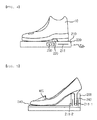
- FIG. 3 is a cross-sectional view of a woman's high heel, which is a kind of footwear able to be wirelessly charged according to the exemplary embodiment of the present invention.
- a description of the some components as the components described with reference to FIGS. 1 and 2 will be omitted for simplification.
- the secondary coil 31 is vertically installed at a side of the heel 30 of the woman's high heel.
- the secondary coil 31 is installed as described above, thereby making it possible to increase a wireless power transmission efficiency.
- FIG. 4 is a view showing an example of a wireless charging device for transmitting a wireless power signal to the footwear able to be wirelessly charged according to the exemplary embodiment of the present invention. That is, as shown in FIG. 4 , in the wireless charging device transmitting a wireless power signal to the footwear able to be wirelessly charged according to the exemplary embodiment of the present invention for removing odor, a portion of a main surface of a base part 200 forms a charging unit 210 and a primary coil 211 is formed under the charging unit 210.
- a catching jaw 220 vertically protrudes from one side of the base part 200 so that the heel 30 may be caught, such that the footwear may be stored so as to have a predetermined gradient in the case in which the footwear is stored in a footwear case.
- FIG. 5 is a view showing another example of a wireless charging device for transmitting a wireless power signal to the footwear able to be wirelessly charged according to the exemplary embodiment of the present invention.
- the secondary coil 31, which is the charging unit is installed at the side, a main surface of the base part 200 is provided with a recess part 240, the recess part 240 is provided with the primary coil, and a support surface 250 capable of supporting a front portion of the footwear is provided.
- the secondary coil 31, which is the charging unit, installed at the side, and the primary coil 211 are maintained to be closely adhered to each other, thereby making it possible to maintain a wireless charging efficiency.
- FIG. 6 is a block diagram for describing an electronic configuration of the footwear able to be wirelessly charged according to the exemplary embodiment of the present invention.
- the footwear able to be wirelessly charged according to the exemplary embodiment of the present invention for removing odor may be configured to include the secondary coil 31, the battery 34, the pressure sensor 60, the ion generator 40, a memory 45, a bio information detecting sensor 70, a communication module 80, and a controller 33.
- the secondary coil 31 the battery 34
- the pressure sensor 60 the ion generator 40
- a memory 45 a bio information detecting sensor 70
- a communication module 80 a communication module 80
- the footwear able to be wirelessly charged according to the exemplary embodiment of the present invention further includes the bio information detecting sensor 70 configured to obtain a pulse information, a body temperature information, or the like.
- the bio information detecting sensor 70 is installed in the receiving space of the footwear to obtain a bio information of the user, and the bio information obtained as described above is stored in the memory 45.
- the controller 33 transmits the bio information stored in the memory 45 to an external electronic device, for example, a mobile communication terminal of the user, a preset hospital server, or the like, via the communication module 80.
- the external electronic device obtaining the bio information transmitted as described above checks a health state of the user by using the bio information and informs the user that the health state is not good by using a pre-stored email information or cellular phone information when it is judged that the health state is not good.
- the footwear when the footwear is stored, it may start to be conveniently charged and an inner portion of the footwear may be sterilized by the ion generator, thereby making it possible to always provide a dry and soft feeling to the user.
- the ion generator is installed in the wear space of the footwear, such that odor of the wear space is removed and sterilization is performed, thereby making it possible to always provide a clean wear environment to the user.
- the battery installed in the footwear may be charged in a wireless charging scheme, inconvenience in use due to replacement of the battery may be solved and a maintenance cost may be decreased.
- the battery since the battery needs not to be replaced, it may be installed in the footwear in a completely closed scheme. As a result, the footwear may be easily manufactured and a problem due to water leakage may be prevented.
- the configurations and the methods of the above-mentioned exemplary embodiments are not restrictively applied. That is, all or some of the respective exemplary embodiments may be selectively combined with each other so that they may be variously modified.
Landscapes
- Engineering & Computer Science (AREA)
- Power Engineering (AREA)
- Computer Networks & Wireless Communication (AREA)
- Microelectronics & Electronic Packaging (AREA)
- Electromagnetism (AREA)
- Physics & Mathematics (AREA)
- Chemical Kinetics & Catalysis (AREA)
- Manufacturing & Machinery (AREA)
- Chemical & Material Sciences (AREA)
- Electrochemistry (AREA)
- General Chemical & Material Sciences (AREA)
- Public Health (AREA)
- General Health & Medical Sciences (AREA)
- Epidemiology (AREA)
- Health & Medical Sciences (AREA)
- Footwear And Its Accessory, Manufacturing Method And Apparatuses (AREA)
- Charge And Discharge Circuits For Batteries Or The Like (AREA)
Abstract
Description
- The present invention relates to a footwear able to be wirelessly charged, capable of providing a clean wear environment through foot odor removal and sterilization without replacing a battery by applying a wireless charging scheme, and a wireless charging device used for the same.
- Generally, a footwear, which is a kind of body protecting means protecting a foot of a walker, always contacts the ground in the state in which it is worn on the foot of a user. Therefore, the footwear absorbs a sweat secreted from the foot, is exposed to an external pollutant as it is, and easily absorbs the external pollutant, such that an inner portion of the footwear becomes always damp. Further, in the inner portion of the footwear, due to an operation of the sweat and the pollutant as described above, various germs may be propagated, odor may be generated, and a disease may be caused in a user's body.
- In order to solve these problems, in the footwear according to the related, the most general method of using a footwear insert having an excellent ventilation property or boring a ventilation hole in an outer cover of the footwear and a method of injecting air into the footwear to ventilate the air have been suggested.
- In addition, according to the related art, the air was injected into the footwear and was ventilated in the footwear to dilute the odor, thereby slightly solving the problems. However, in this scheme, an effect is small and the problems may not be fundamentally solved.
- Meanwhile, in the case in which an electronic component is mounted in the footwear in order to implement a sanitary function, it is required to continuously supply a power. However, since it is difficult to supply the power from an outer portion of the footwear due to characteristics of the footwear, a battery should be mounted in the footwear.
- Generally, since the battery has a limitation in a use time, it should be periodically replaced, which is inconvenient in view of maintenance and causes a cost increase. In addition, there is a risk that moisture will be permeated from the outer portion of the footwear through a replacement portion.
- An object of the present invention is to provide a footwear able to be wirelessly charged, capable of removing odor in the footwear and performing sterilization, and being semi-permanently used without replacing a battery, and a wireless charging device used for the same.
- According to an exemplary embodiment of the present invention, there is provided a footwear able to be wirelessly charged, the footwear including: an insole; an outer cover installed on the insole and having a wear space formed therein; a heel attached to a lower surface of the insole; an ion generator installed in the wear space to apply an ion into the wear space; a battery installed in any one of the insole, the outer cover, and the heel and applying a power to the ion generator; a secondary coil installed in any one of the insole, the outer cover, and the heel and receiving a wireless power signal from an external device; a rectifying module configured to rectify an induced electromotive force generated from the secondary coil; and a controller configured to charge the battery by receiving a power from the rectifying module and control an operation of the ion generator by controlling the battery.
- The battery, the secondary coil, the rectifying module and the controller may be installed in the heel, and the heel may further include a shielding plate configured to prevent a magnetic field of the secondary coil from being leaked to the rectifying module or the controller.
- The heel and the insole may be waterproofly attached to each other.
- The footwear may further include a wear detecting sensor installed in any one of the insole and the outer cover to detect whether a user wears the footwear, wherein the controller is configured to control the ion generator based on a signal from the wear detecting sensor.
- The wear detecting sensor may be a pressure sensor installed at a portion of an upper surface of the insole, the portion corresponding to the heel, and the controller may include a timer to operate the ion generator at a predetermined period.
- The secondary coil may be installed in the heel in a direction vertical or horizontal to the bottom surface of the heel.
- The secondary coil may include a first sub coil and a second sub coil installed on the first sub coil so as to be overlapped with the first sub coil.
- The footwear may further include: a bio information detecting sensor installed in the wear space to detect a bio information of a user; a memory installed in any one of the insole, the outer cover, and the heel to store the bio information detected by the bio information detecting sensor; and a communication module configured to transmit the bio information stored in the memory to an external electronic device.
- According to another exemplary embodiment of the present invention, there is provided a wireless charging device for transmitting a wireless power signal to the footwear as described above, the wireless charging device including: a base part having the footwear hung thereon; and a charging unit installed on the base part and having a primary coil installed in a position thereof corresponding to that of the secondary coil of the footwear.
- According to still another exemplary embodiment of the present invention, there is provided a wireless charging device for transmitting a wireless power signal to the footwear as described above, the wireless charging device including: a base part having the footwear hung thereon and provided with a recess part into which the heel of the footwear is inserted; and a charging unit installed at the recess part and having a primary coil installed in a position thereof corresponding to that of the secondary coil of the footwear.
-
-
FIG. 1 is a perspective view showing an example of a footwear able to be wirelessly charged according to an exemplary embodiment of the present invention; -
FIG. 2 is a cross-sectional view of the footwear able to be wirelessly charged shown inFIG. 1 ; -
FIG. 3 is a cross-sectional view of a woman's high heel, which is a kind of footwear able to be wirelessly charged according to the exemplary embodiment of the present invention; -
FIG. 4 is a view showing an example of a wireless charging device for transmitting a wireless power signal to the footwear able to be wirelessly charged according to the exemplary embodiment of the present invention; -
FIG. 5 is a view showing another example of a wireless charging device for transmitting a wireless power signal to the footwear able to be wirelessly charged according to the exemplary embodiment of the present invention; and -
FIG. 6 is a block diagram for describing an electronic configuration of the footwear able to be wirelessly charged according to the exemplary embodiment of the present invention. - Hereinafter, a footwear able to be wirelessly charged according to an exemplary embodiment of the present invention and a wireless charging device used for the same will be described in detail with reference to the accompanying drawings.
-
FIG. 1 is a perspective view showing an example of a footwear able to be wirelessly charged according to an exemplary embodiment of the present invention; andFIG. 2 is a cross-sectional view of the footwear able to be wirelessly charged, shown inFIG. 1 . As shown inFIGS. 1 and2 , thefootwear 100 able to be wirelessly charged according to the exemplary embodiment of the present invention is configured to include aninsole 20; anouter cover 10 formed on theinsole 20 and having a wear space formed therein; and aheel 30 attached to a rear part of theinsole 20. As shown inFIG. 2 , anion generator 40 for removing odor is attached to theinsole 20, and a wireless power receiving device and abattery 34 are installed in the heel. Although theion generator 40 has been installed in the insole in the detailed description of the present invention, the present invention is not limited thereto. That is, it is to be understood that theion generator 40 may be installed in any receiving space formed by theouter cover 10 and the insole. - In addition, the wireless power receiving device may include a secondary coil configured to receive a power signal from a wireless charging device to be described below and a rectifying module (not shown) configured to rectify an induced electromotive force generated from the
secondary coil 31. - In addition, the
heel 30 is further provided with thebattery 34 charged with a power from thesecondary coil 31, aboard 33 on which a controller configured to control the wireless power receiving device and thebattery 34 to control an operation of theion generator 40 is installed, and ashielding plate 32 installed on thesecondary coil 31 to prevent a leaked magnetic field from affecting the board or thebattery 34. - Here, the
secondary coil 31 may include a first sub coil and a second sub coil installed on the first sub coil so as to be overlapped with the first sub coil in a longitudinal direction, in order to increase a transmission efficiency. That is, in the case in which a cross-sectional width of the heel is not wide, such that it is difficult to form thesecondary coil 31 having a sufficient size, two coils are installed to be overlapped with each other, thereby making it possible to increase a reception efficiency of the wireless power signal. - In addition, a
pressure sensor 60 may be attached to a portion corresponding to the heel to control a turn on/off of theion generator 40. That is, through thepressure sensor 60, an operation of theion generator 40 may stop when it is judged that a user is in the state in which he/she wears the footwear and start when it is judged that the user is in the state in which he/she takes off the footwear. Alternatively, the controller may operate theion generator 40 at a predetermined period based on a signal from thepressure sensor 60. - Although the pressure sensor has been used as the detecting sensor detecting whether or not the user wears the footwear in the detailed description of the present invention, the present invention is not limited thereto. That is, it is to be understood that various detecting sensors may be installed in the outer cover or the insole to detect whether or not the user wears the footwear.
- Meanwhile, a
flexible circuit board 50 may be used in order to connect theboard 33 and theion generator 40 to each other. When a person walks or runs, the insole 20 of thefootwear 100 is bent. In this case, when theflexible circuit board 50 is used as an electrical connection means between theion generator 50 and theboard 33, even though theinsole 20 is bent, durability is not affected at all. - Although an example in which the battery, the board, and the wireless power receiving device are installed in the heel has been described in the detailed description of the present invention, the present invention is not limited thereto. That is, it is to be understood that the battery, the board, and the wireless power receiving device may also be installed in the insole or the outer cover depending on a use aspect, or the like.
-
FIG. 3 is a cross-sectional view of a woman's high heel, which is a kind of footwear able to be wirelessly charged according to the exemplary embodiment of the present invention. A description of the some components as the components described with reference toFIGS. 1 and2 will be omitted for simplification. - In the case of the woman's high heel, although a size of a horizontal cross section is small, a size of a vertical cross section is large. In consideration of this feature, as shown in
FIG. 3 , thesecondary coil 31 is vertically installed at a side of theheel 30 of the woman's high heel. Thesecondary coil 31 is installed as described above, thereby making it possible to increase a wireless power transmission efficiency. - Hereinafter, a wireless charging device for charging the footwear able to be wirelessly charged, having the above-mentioned configuration will be described with reference to
FIGS. 4 and 5 . -
FIG. 4 is a view showing an example of a wireless charging device for transmitting a wireless power signal to the footwear able to be wirelessly charged according to the exemplary embodiment of the present invention. That is, as shown inFIG. 4 , in the wireless charging device transmitting a wireless power signal to the footwear able to be wirelessly charged according to the exemplary embodiment of the present invention for removing odor, a portion of a main surface of abase part 200 forms acharging unit 210 and aprimary coil 211 is formed under thecharging unit 210. In addition, acatching jaw 220 vertically protrudes from one side of thebase part 200 so that theheel 30 may be caught, such that the footwear may be stored so as to have a predetermined gradient in the case in which the footwear is stored in a footwear case. Through the above-mentioned configuration, since theprimary coil 211 and thesecondary coil 31 are closely adhered to each other even in the inclined state, a wireless charging efficiency may be secured. -
FIG. 5 is a view showing another example of a wireless charging device for transmitting a wireless power signal to the footwear able to be wirelessly charged according to the exemplary embodiment of the present invention. As shown inFIG. 5 , in the case in which the woman's high heel ofFIG. 3 is to be charged, since thesecondary coil 31, which is the charging unit, is installed at the side, a main surface of thebase part 200 is provided with arecess part 240, therecess part 240 is provided with the primary coil, and a support surface 250 capable of supporting a front portion of the footwear is provided. Through the above-mentioned configuration, thesecondary coil 31, which is the charging unit, installed at the side, and theprimary coil 211 are maintained to be closely adhered to each other, thereby making it possible to maintain a wireless charging efficiency. -
FIG. 6 is a block diagram for describing an electronic configuration of the footwear able to be wirelessly charged according to the exemplary embodiment of the present invention. As shown inFIG. 6 , the footwear able to be wirelessly charged according to the exemplary embodiment of the present invention for removing odor may be configured to include thesecondary coil 31, thebattery 34, thepressure sensor 60, theion generator 40, amemory 45, a bioinformation detecting sensor 70, acommunication module 80, and acontroller 33. A description of the above-mentioned contents in operations of these components will be omitted for simplification. - As shown in
FIG. 6 , according to the exemplary embodiment of the present invention, the footwear able to be wirelessly charged according to the exemplary embodiment of the present invention further includes the bioinformation detecting sensor 70 configured to obtain a pulse information, a body temperature information, or the like. The bioinformation detecting sensor 70 is installed in the receiving space of the footwear to obtain a bio information of the user, and the bio information obtained as described above is stored in thememory 45. Thecontroller 33 transmits the bio information stored in thememory 45 to an external electronic device, for example, a mobile communication terminal of the user, a preset hospital server, or the like, via thecommunication module 80. The external electronic device obtaining the bio information transmitted as described above checks a health state of the user by using the bio information and informs the user that the health state is not good by using a pre-stored email information or cellular phone information when it is judged that the health state is not good. - According to the exemplary embodiment of the present inventi on having the above-mentioned configuration, since the battery is charged in a wireless charging scheme, a waterproof function is provided at a low cost, thereby making it possible to increase durability.
- In addition, when the footwear is stored, it may start to be conveniently charged and an inner portion of the footwear may be sterilized by the ion generator, thereby making it possible to always provide a dry and soft feeling to the user.
- According to the exemplary embodiment of the present invention having the above-mentioned configuration, the ion generator is installed in the wear space of the footwear, such that odor of the wear space is removed and sterilization is performed, thereby making it possible to always provide a clean wear environment to the user.
- In addition, since the battery installed in the footwear may be charged in a wireless charging scheme, inconvenience in use due to replacement of the battery may be solved and a maintenance cost may be decreased.
- Meanwhile, since the battery needs not to be replaced, it may be installed in the footwear in a completely closed scheme. As a result, the footwear may be easily manufactured and a problem due to water leakage may be prevented.
- In the footwear able to be wirelessly charged and the wireless charging device used for the same according to the exemplary embodiment of the present invention as described above, the configurations and the methods of the above-mentioned exemplary embodiments are not restrictively applied. That is, all or some of the respective exemplary embodiments may be selectively combined with each other so that they may be variously modified.
Claims (10)
- A footwear able to be wirelessly charged, the footwear comprising:an insole;an outer cover installed on the insole and having a wear space formed therein;a heel attached to a lower surface of the insole;an ion generator installed in the wear space to apply an ion into the wear space;a battery installed in any one of the insole, the outer cover, and the heel and applying a power to the ion generator;a secondary coil installed in any one of the insole, the outer cover, and the heel and receiving a wireless power signal from an external device;a rectifying module configured to rectify an induced electromotive force generated from the secondary coil; anda controller configured to charge the battery by receiving a power from the rectifying module and control an operation of the ion generator by controlling the battery.
- The footwear of claim 1, wherein the battery, the secondary coil, the rectifying module and the controller are installed in the heel, and the heel further includes a shielding plate configured to prevent a magnetic field of the secondary coil from being leaked to the rectifying module or the controller.
- The footwear of claim 1, wherein the heel and the insole are waterproofly attached to each other.
- The footwear of the claim 1, further comprising a wear detecting sensor installed in any one of the insole and the outer cover to detect whether a user wears the footwear,
wherein the controller is configured to control the ion generator based on a signal from the wear detecting sensor. - The footwear of claim 4, wherein the wear detecting sensor is a pressure sensor installed at a portion of an upper surface of the insole, the portion corresponding to the heel, and
the controller includes a timer to operate the ion generator at a predetermined period. - The footwear of claim 1, wherein the secondary coil is installed in the heel in a direction vertical or horizontal to the bottom surface of the heel.
- The footwear of claim 1, wherein the secondary coil includes a first sub coil and a second sub coil installed on the first sub coil so as to be overlapped with the first sub coil.
- The footwear of claim 1, further comprising:a bio information detecting sensor installed in the wear space to detect a bio information of a user;a memory installed in any one of the insole, the outer cover, and the heel to store the bio information detected by the bio information detecting sensor; anda communication module configured to transmit the bio information stored in the memory to an external electronic device.
- A wireless charging device for transmitting a wireless power signal to the footwear of claim 1, the wireless charging device comprising:a base part having the footwear hung thereon; anda charging unit installed on the base part and having a primary coil installed in a position thereof corresponding to that of the secondary coil of the footwear.
- A wireless charging device for transmitting a wireless power signal to the footwear of claim 2, the wireless charging device comprising:a base part having the footwear hung thereon and provided with a recess part into which the heel of the footwear is inserted; anda charging unit installed at the recess part and having a primary coil installed in a position thereof corresponding to that of the secondary coil of the footwear.
Applications Claiming Priority (1)
| Application Number | Priority Date | Filing Date | Title |
|---|---|---|---|
| KR1020120126924A KR102006027B1 (en) | 2012-11-09 | 2012-11-09 | Wireless chargeable shoes and wireless charger used therein |
Publications (2)
| Publication Number | Publication Date |
|---|---|
| EP2731228A1 true EP2731228A1 (en) | 2014-05-14 |
| EP2731228B1 EP2731228B1 (en) | 2016-02-24 |
Family
ID=49552217
Family Applications (1)
| Application Number | Title | Priority Date | Filing Date |
|---|---|---|---|
| EP13191975.5A Not-in-force EP2731228B1 (en) | 2012-11-09 | 2013-11-07 | Footwear able to be wirelessly charged |
Country Status (4)
| Country | Link |
|---|---|
| US (1) | US20140130381A1 (en) |
| EP (1) | EP2731228B1 (en) |
| KR (1) | KR102006027B1 (en) |
| CN (1) | CN103799610A (en) |
Families Citing this family (17)
| Publication number | Priority date | Publication date | Assignee | Title |
|---|---|---|---|---|
| CN104822284B (en) | 2012-08-31 | 2016-10-19 | 耐克创新有限合伙公司 | Motorized tensioning system with sensor |
| US20160183628A1 (en) * | 2014-12-30 | 2016-06-30 | Clancy Usifoh | Therapeutic vibration shoe device |
| US10439422B2 (en) * | 2015-01-20 | 2019-10-08 | David Singer | Wireless power transfer to a medical computer cart |
| US10231505B2 (en) | 2015-05-28 | 2019-03-19 | Nike, Inc. | Article of footwear and a charging system for an article of footwear |
| EP4070682A1 (en) * | 2015-05-29 | 2022-10-12 | Nike Innovate C.V. | Motorized tensioning device with compact spool system |
| KR101690005B1 (en) * | 2015-08-21 | 2017-01-09 | 주식회사 제이드엠 | Error Range Reduced Possible Global Positioning System Of Smart Shoes |
| KR20170110802A (en) * | 2016-03-24 | 2017-10-12 | 엘지이노텍 주식회사 | A wireless power receiver and thereof operation method |
| CN105996287A (en) * | 2016-05-27 | 2016-10-12 | 张蜀军 | Intelligent sterilizing sanitary shoes |
| AT518546B1 (en) | 2016-09-27 | 2017-11-15 | Stapptronics Gmbh | Insole or shoe sole |
| CN108695915A (en) * | 2017-04-07 | 2018-10-23 | 丁明照 | It is a kind of can deodorization and sterilization wireless charger |
| CN107242633A (en) * | 2017-06-04 | 2017-10-13 | 福建省晋江市陈埭江头茂泰橡塑厂 | A kind of automatic lace loop of Intellisense and its method |
| CN107242637A (en) * | 2017-08-09 | 2017-10-13 | 邵辉 | A kind of intelligent sterilizing methods of built-in shoes |
| US11382383B2 (en) | 2019-02-11 | 2022-07-12 | Brilliant Sole, Inc. | Smart footwear with wireless charging |
| KR102398480B1 (en) * | 2020-07-31 | 2022-05-16 | 주식회사 슈올즈 | Shoes interlocked with the app |
| KR20240058443A (en) * | 2022-10-26 | 2024-05-03 | 삼성전자주식회사 | Wearable apparatus performing wireless power transmission and wireless communication and operating method thereof |
| US11737507B1 (en) * | 2022-10-28 | 2023-08-29 | The Florida International University Board Of Trustees | Intelligent automated footwear |
| KR102889740B1 (en) * | 2023-09-25 | 2025-11-20 | 한서대학교 산학협력단 | Health management system for the elderly using smart shoes |
Citations (5)
| Publication number | Priority date | Publication date | Assignee | Title |
|---|---|---|---|---|
| KR20100087442A (en) * | 2009-01-28 | 2010-08-05 | 이용식 | Shoes with anion generator |
| CN201995701U (en) * | 2011-04-07 | 2011-10-05 | 宋琳 | Wireless rechargeable automatic temperature control warmth-keeping shoe |
| KR20120045420A (en) * | 2010-10-29 | 2012-05-09 | 이수덕 | Apparatus and method for wirelessly charging battery of shoes with electronic device |
| WO2012162140A2 (en) * | 2011-05-20 | 2012-11-29 | Brian James Vogt | Method and apparatus for cooling footwear |
| KR20130085606A (en) * | 2012-01-20 | 2013-07-30 | 김병엽 | Wirelessly chargable indoor shoes for heating and wireless charging apparatus of the indoor shoes |
Family Cites Families (9)
| Publication number | Priority date | Publication date | Assignee | Title |
|---|---|---|---|---|
| US6230501B1 (en) * | 1994-04-14 | 2001-05-15 | Promxd Technology, Inc. | Ergonomic systems and methods providing intelligent adaptive surfaces and temperature control |
| US7204041B1 (en) * | 1997-08-14 | 2007-04-17 | Promdx Technology, Inc. | Ergonomic systems and methods providing intelligent adaptive surfaces |
| US6255799B1 (en) * | 1998-12-30 | 2001-07-03 | The Johns Hopkins University | Rechargeable shoe |
| KR200410569Y1 (en) * | 2005-12-02 | 2006-03-13 | 김경현 | Insole with built-in heating means |
| US8356430B2 (en) * | 2010-02-11 | 2013-01-22 | Nike, Inc. | Article of footwear incorporating an illuminable fluid-filled chamber |
| US8544197B2 (en) * | 2010-02-11 | 2013-10-01 | Nike, Inc. | Article of footwear incorporating an illuminable panel |
| US20120317843A1 (en) * | 2011-06-20 | 2012-12-20 | Thomas Bove | Shoe sole system providing a negative ion environment |
| US20150068069A1 (en) * | 2013-07-27 | 2015-03-12 | Alexander Bach Tran | Personally powered appliance |
| CA2930858C (en) * | 2013-12-04 | 2021-01-26 | Schawbel Technologies Llc | Heated insole with removable and rechargeable battery |
-
2012
- 2012-11-09 KR KR1020120126924A patent/KR102006027B1/en active Active
-
2013
- 2013-11-07 US US14/074,489 patent/US20140130381A1/en not_active Abandoned
- 2013-11-07 EP EP13191975.5A patent/EP2731228B1/en not_active Not-in-force
- 2013-11-08 CN CN201310552645.1A patent/CN103799610A/en active Pending
Patent Citations (5)
| Publication number | Priority date | Publication date | Assignee | Title |
|---|---|---|---|---|
| KR20100087442A (en) * | 2009-01-28 | 2010-08-05 | 이용식 | Shoes with anion generator |
| KR20120045420A (en) * | 2010-10-29 | 2012-05-09 | 이수덕 | Apparatus and method for wirelessly charging battery of shoes with electronic device |
| CN201995701U (en) * | 2011-04-07 | 2011-10-05 | 宋琳 | Wireless rechargeable automatic temperature control warmth-keeping shoe |
| WO2012162140A2 (en) * | 2011-05-20 | 2012-11-29 | Brian James Vogt | Method and apparatus for cooling footwear |
| KR20130085606A (en) * | 2012-01-20 | 2013-07-30 | 김병엽 | Wirelessly chargable indoor shoes for heating and wireless charging apparatus of the indoor shoes |
Also Published As
| Publication number | Publication date |
|---|---|
| KR102006027B1 (en) | 2019-07-31 |
| KR20140060159A (en) | 2014-05-19 |
| EP2731228B1 (en) | 2016-02-24 |
| US20140130381A1 (en) | 2014-05-15 |
| CN103799610A (en) | 2014-05-21 |
Similar Documents
| Publication | Publication Date | Title |
|---|---|---|
| EP2731228B1 (en) | Footwear able to be wirelessly charged | |
| KR101191800B1 (en) | Shoe insole for walk diagnosis | |
| JP6419866B2 (en) | Energy acquisition sole | |
| US8831715B2 (en) | ECG hand-held device | |
| US9839236B2 (en) | Electronic cigarette case and information acquisition method | |
| CA2991926C (en) | Device for avoiding excessive loads on the human foot when walking and operating method therefor | |
| US20140091926A1 (en) | System and method for reducing medical error | |
| EP4238432B1 (en) | Aerosol generation device | |
| KR20190023687A (en) | Sterilizable skin care device for wrinkle care | |
| KR20190134462A (en) | Diaper for sensing urine and feces, urine and feces sensing sheet for diaper and urine and feces sensing device | |
| KR101629280B1 (en) | controllable heating gloves by smart portable devices | |
| KR101588837B1 (en) | Heating shoes that radio charge is possible | |
| KR20120045420A (en) | Apparatus and method for wirelessly charging battery of shoes with electronic device | |
| KR20110067771A (en) | Shoe insole and health care system including it | |
| CN205306975U (en) | Intelligence position of sitting orthotic devices | |
| KR101901852B1 (en) | Smart insole using eco-friendly energy | |
| KR20160084271A (en) | Smart Insole and Smart Insole-Sensorpack set with combinable and seperable sensorpack for getting information on exercise | |
| KR200480844Y1 (en) | Posture correcting device | |
| JP5898457B2 (en) | Shoes used for walking training | |
| KR20240008035A (en) | Power supply with alternative power source for smart insole | |
| JP2003169702A (en) | Location-reporting shoe and location-reporting midsole thereof | |
| KR102109680B1 (en) | Smart managing system for walking | |
| KR101408692B1 (en) | Insole with position pursuit function | |
| KR20180135673A (en) | patch type sensor module | |
| JP2014230062A (en) | Id tag, shoes, id tag system and id information transmission method |
Legal Events
| Date | Code | Title | Description |
|---|---|---|---|
| PUAI | Public reference made under article 153(3) epc to a published international application that has entered the european phase |
Free format text: ORIGINAL CODE: 0009012 |
|
| 17P | Request for examination filed |
Effective date: 20131107 |
|
| AK | Designated contracting states |
Kind code of ref document: A1 Designated state(s): AL AT BE BG CH CY CZ DE DK EE ES FI FR GB GR HR HU IE IS IT LI LT LU LV MC MK MT NL NO PL PT RO RS SE SI SK SM TR |
|
| AX | Request for extension of the european patent |
Extension state: BA ME |
|
| R17P | Request for examination filed (corrected) |
Effective date: 20141113 |
|
| RBV | Designated contracting states (corrected) |
Designated state(s): AL AT BE BG CH CY CZ DE DK EE ES FI FR GB GR HR HU IE IS IT LI LT LU LV MC MK MT NL NO PL PT RO RS SE SI SK SM TR |
|
| GRAP | Despatch of communication of intention to grant a patent |
Free format text: ORIGINAL CODE: EPIDOSNIGR1 |
|
| RIC1 | Information provided on ipc code assigned before grant |
Ipc: A43B 1/00 20060101ALI20150714BHEP Ipc: H02J 7/02 20060101AFI20150714BHEP Ipc: A43B 3/00 20060101ALI20150714BHEP |
|
| INTG | Intention to grant announced |
Effective date: 20150819 |
|
| RAP1 | Party data changed (applicant data changed or rights of an application transferred) |
Owner name: HANRIM POSTECH CO., LTD |
|
| GRAS | Grant fee paid |
Free format text: ORIGINAL CODE: EPIDOSNIGR3 |
|
| GRAA | (expected) grant |
Free format text: ORIGINAL CODE: 0009210 |
|
| AK | Designated contracting states |
Kind code of ref document: B1 Designated state(s): AL AT BE BG CH CY CZ DE DK EE ES FI FR GB GR HR HU IE IS IT LI LT LU LV MC MK MT NL NO PL PT RO RS SE SI SK SM TR |
|
| REG | Reference to a national code |
Ref country code: GB Ref legal event code: FG4D |
|
| REG | Reference to a national code |
Ref country code: CH Ref legal event code: EP |
|
| REG | Reference to a national code |
Ref country code: AT Ref legal event code: REF Ref document number: 777182 Country of ref document: AT Kind code of ref document: T Effective date: 20160315 |
|
| REG | Reference to a national code |
Ref country code: IE Ref legal event code: FG4D |
|
| REG | Reference to a national code |
Ref country code: DE Ref legal event code: R096 Ref document number: 602013005132 Country of ref document: DE |
|
| REG | Reference to a national code |
Ref country code: LT Ref legal event code: MG4D |
|
| REG | Reference to a national code |
Ref country code: NL Ref legal event code: MP Effective date: 20160224 |
|
| REG | Reference to a national code |
Ref country code: AT Ref legal event code: MK05 Ref document number: 777182 Country of ref document: AT Kind code of ref document: T Effective date: 20160224 |
|
| PG25 | Lapsed in a contracting state [announced via postgrant information from national office to epo] |
Ref country code: GR Free format text: LAPSE BECAUSE OF FAILURE TO SUBMIT A TRANSLATION OF THE DESCRIPTION OR TO PAY THE FEE WITHIN THE PRESCRIBED TIME-LIMIT Effective date: 20160525 Ref country code: ES Free format text: LAPSE BECAUSE OF FAILURE TO SUBMIT A TRANSLATION OF THE DESCRIPTION OR TO PAY THE FEE WITHIN THE PRESCRIBED TIME-LIMIT Effective date: 20160224 Ref country code: FI Free format text: LAPSE BECAUSE OF FAILURE TO SUBMIT A TRANSLATION OF THE DESCRIPTION OR TO PAY THE FEE WITHIN THE PRESCRIBED TIME-LIMIT Effective date: 20160224 Ref country code: NO Free format text: LAPSE BECAUSE OF FAILURE TO SUBMIT A TRANSLATION OF THE DESCRIPTION OR TO PAY THE FEE WITHIN THE PRESCRIBED TIME-LIMIT Effective date: 20160524 Ref country code: IT Free format text: LAPSE BECAUSE OF FAILURE TO SUBMIT A TRANSLATION OF THE DESCRIPTION OR TO PAY THE FEE WITHIN THE PRESCRIBED TIME-LIMIT Effective date: 20160224 Ref country code: HR Free format text: LAPSE BECAUSE OF FAILURE TO SUBMIT A TRANSLATION OF THE DESCRIPTION OR TO PAY THE FEE WITHIN THE PRESCRIBED TIME-LIMIT Effective date: 20160224 |
|
| PG25 | Lapsed in a contracting state [announced via postgrant information from national office to epo] |
Ref country code: LV Free format text: LAPSE BECAUSE OF FAILURE TO SUBMIT A TRANSLATION OF THE DESCRIPTION OR TO PAY THE FEE WITHIN THE PRESCRIBED TIME-LIMIT Effective date: 20160224 Ref country code: PL Free format text: LAPSE BECAUSE OF FAILURE TO SUBMIT A TRANSLATION OF THE DESCRIPTION OR TO PAY THE FEE WITHIN THE PRESCRIBED TIME-LIMIT Effective date: 20160224 Ref country code: SE Free format text: LAPSE BECAUSE OF FAILURE TO SUBMIT A TRANSLATION OF THE DESCRIPTION OR TO PAY THE FEE WITHIN THE PRESCRIBED TIME-LIMIT Effective date: 20160224 Ref country code: NL Free format text: LAPSE BECAUSE OF FAILURE TO SUBMIT A TRANSLATION OF THE DESCRIPTION OR TO PAY THE FEE WITHIN THE PRESCRIBED TIME-LIMIT Effective date: 20160224 Ref country code: AT Free format text: LAPSE BECAUSE OF FAILURE TO SUBMIT A TRANSLATION OF THE DESCRIPTION OR TO PAY THE FEE WITHIN THE PRESCRIBED TIME-LIMIT Effective date: 20160224 Ref country code: RS Free format text: LAPSE BECAUSE OF FAILURE TO SUBMIT A TRANSLATION OF THE DESCRIPTION OR TO PAY THE FEE WITHIN THE PRESCRIBED TIME-LIMIT Effective date: 20160224 Ref country code: LT Free format text: LAPSE BECAUSE OF FAILURE TO SUBMIT A TRANSLATION OF THE DESCRIPTION OR TO PAY THE FEE WITHIN THE PRESCRIBED TIME-LIMIT Effective date: 20160224 Ref country code: PT Free format text: LAPSE BECAUSE OF FAILURE TO SUBMIT A TRANSLATION OF THE DESCRIPTION OR TO PAY THE FEE WITHIN THE PRESCRIBED TIME-LIMIT Effective date: 20160624 |
|
| PG25 | Lapsed in a contracting state [announced via postgrant information from national office to epo] |
Ref country code: EE Free format text: LAPSE BECAUSE OF FAILURE TO SUBMIT A TRANSLATION OF THE DESCRIPTION OR TO PAY THE FEE WITHIN THE PRESCRIBED TIME-LIMIT Effective date: 20160224 Ref country code: DK Free format text: LAPSE BECAUSE OF FAILURE TO SUBMIT A TRANSLATION OF THE DESCRIPTION OR TO PAY THE FEE WITHIN THE PRESCRIBED TIME-LIMIT Effective date: 20160224 |
|
| REG | Reference to a national code |
Ref country code: DE Ref legal event code: R097 Ref document number: 602013005132 Country of ref document: DE |
|
| PG25 | Lapsed in a contracting state [announced via postgrant information from national office to epo] |
Ref country code: CZ Free format text: LAPSE BECAUSE OF FAILURE TO SUBMIT A TRANSLATION OF THE DESCRIPTION OR TO PAY THE FEE WITHIN THE PRESCRIBED TIME-LIMIT Effective date: 20160224 Ref country code: RO Free format text: LAPSE BECAUSE OF FAILURE TO SUBMIT A TRANSLATION OF THE DESCRIPTION OR TO PAY THE FEE WITHIN THE PRESCRIBED TIME-LIMIT Effective date: 20160224 Ref country code: SK Free format text: LAPSE BECAUSE OF FAILURE TO SUBMIT A TRANSLATION OF THE DESCRIPTION OR TO PAY THE FEE WITHIN THE PRESCRIBED TIME-LIMIT Effective date: 20160224 Ref country code: SM Free format text: LAPSE BECAUSE OF FAILURE TO SUBMIT A TRANSLATION OF THE DESCRIPTION OR TO PAY THE FEE WITHIN THE PRESCRIBED TIME-LIMIT Effective date: 20160224 |
|
| PG25 | Lapsed in a contracting state [announced via postgrant information from national office to epo] |
Ref country code: BE Free format text: LAPSE BECAUSE OF FAILURE TO SUBMIT A TRANSLATION OF THE DESCRIPTION OR TO PAY THE FEE WITHIN THE PRESCRIBED TIME-LIMIT Effective date: 20160224 |
|
| PLBE | No opposition filed within time limit |
Free format text: ORIGINAL CODE: 0009261 |
|
| STAA | Information on the status of an ep patent application or granted ep patent |
Free format text: STATUS: NO OPPOSITION FILED WITHIN TIME LIMIT |
|
| 26N | No opposition filed |
Effective date: 20161125 |
|
| PG25 | Lapsed in a contracting state [announced via postgrant information from national office to epo] |
Ref country code: BG Free format text: LAPSE BECAUSE OF FAILURE TO SUBMIT A TRANSLATION OF THE DESCRIPTION OR TO PAY THE FEE WITHIN THE PRESCRIBED TIME-LIMIT Effective date: 20160524 Ref country code: SI Free format text: LAPSE BECAUSE OF FAILURE TO SUBMIT A TRANSLATION OF THE DESCRIPTION OR TO PAY THE FEE WITHIN THE PRESCRIBED TIME-LIMIT Effective date: 20160224 |
|
| REG | Reference to a national code |
Ref country code: DE Ref legal event code: R119 Ref document number: 602013005132 Country of ref document: DE |
|
| REG | Reference to a national code |
Ref country code: CH Ref legal event code: PL |
|
| PG25 | Lapsed in a contracting state [announced via postgrant information from national office to epo] |
Ref country code: CH Free format text: LAPSE BECAUSE OF NON-PAYMENT OF DUE FEES Effective date: 20161130 Ref country code: LI Free format text: LAPSE BECAUSE OF NON-PAYMENT OF DUE FEES Effective date: 20161130 |
|
| REG | Reference to a national code |
Ref country code: IE Ref legal event code: MM4A |
|
| REG | Reference to a national code |
Ref country code: FR Ref legal event code: ST Effective date: 20170731 |
|
| PG25 | Lapsed in a contracting state [announced via postgrant information from national office to epo] |
Ref country code: LU Free format text: LAPSE BECAUSE OF NON-PAYMENT OF DUE FEES Effective date: 20161130 |
|
| PG25 | Lapsed in a contracting state [announced via postgrant information from national office to epo] |
Ref country code: FR Free format text: LAPSE BECAUSE OF NON-PAYMENT OF DUE FEES Effective date: 20161130 |
|
| PG25 | Lapsed in a contracting state [announced via postgrant information from national office to epo] |
Ref country code: IE Free format text: LAPSE BECAUSE OF NON-PAYMENT OF DUE FEES Effective date: 20161107 Ref country code: DE Free format text: LAPSE BECAUSE OF NON-PAYMENT OF DUE FEES Effective date: 20170601 |
|
| PG25 | Lapsed in a contracting state [announced via postgrant information from national office to epo] |
Ref country code: HU Free format text: LAPSE BECAUSE OF FAILURE TO SUBMIT A TRANSLATION OF THE DESCRIPTION OR TO PAY THE FEE WITHIN THE PRESCRIBED TIME-LIMIT; INVALID AB INITIO Effective date: 20131107 Ref country code: CY Free format text: LAPSE BECAUSE OF FAILURE TO SUBMIT A TRANSLATION OF THE DESCRIPTION OR TO PAY THE FEE WITHIN THE PRESCRIBED TIME-LIMIT Effective date: 20160224 |
|
| PG25 | Lapsed in a contracting state [announced via postgrant information from national office to epo] |
Ref country code: MC Free format text: LAPSE BECAUSE OF FAILURE TO SUBMIT A TRANSLATION OF THE DESCRIPTION OR TO PAY THE FEE WITHIN THE PRESCRIBED TIME-LIMIT Effective date: 20160224 Ref country code: MK Free format text: LAPSE BECAUSE OF FAILURE TO SUBMIT A TRANSLATION OF THE DESCRIPTION OR TO PAY THE FEE WITHIN THE PRESCRIBED TIME-LIMIT Effective date: 20160224 Ref country code: IS Free format text: LAPSE BECAUSE OF FAILURE TO SUBMIT A TRANSLATION OF THE DESCRIPTION OR TO PAY THE FEE WITHIN THE PRESCRIBED TIME-LIMIT Effective date: 20160224 |
|
| GBPC | Gb: european patent ceased through non-payment of renewal fee |
Effective date: 20171107 |
|
| PG25 | Lapsed in a contracting state [announced via postgrant information from national office to epo] |
Ref country code: MT Free format text: LAPSE BECAUSE OF NON-PAYMENT OF DUE FEES Effective date: 20161107 |
|
| PG25 | Lapsed in a contracting state [announced via postgrant information from national office to epo] |
Ref country code: AL Free format text: LAPSE BECAUSE OF FAILURE TO SUBMIT A TRANSLATION OF THE DESCRIPTION OR TO PAY THE FEE WITHIN THE PRESCRIBED TIME-LIMIT Effective date: 20160224 Ref country code: TR Free format text: LAPSE BECAUSE OF FAILURE TO SUBMIT A TRANSLATION OF THE DESCRIPTION OR TO PAY THE FEE WITHIN THE PRESCRIBED TIME-LIMIT Effective date: 20160224 |
|
| PG25 | Lapsed in a contracting state [announced via postgrant information from national office to epo] |
Ref country code: GB Free format text: LAPSE BECAUSE OF NON-PAYMENT OF DUE FEES Effective date: 20171107 |