EP2730829B1 - Kunststoffrohr - Google Patents
Kunststoffrohr Download PDFInfo
- Publication number
- EP2730829B1 EP2730829B1 EP13176951.5A EP13176951A EP2730829B1 EP 2730829 B1 EP2730829 B1 EP 2730829B1 EP 13176951 A EP13176951 A EP 13176951A EP 2730829 B1 EP2730829 B1 EP 2730829B1
- Authority
- EP
- European Patent Office
- Prior art keywords
- plastic pipe
- welding
- reinforcing
- plastic
- pipe
- Prior art date
- Legal status (The legal status is an assumption and is not a legal conclusion. Google has not performed a legal analysis and makes no representation as to the accuracy of the status listed.)
- Active
Links
Images




Classifications
-
- B—PERFORMING OPERATIONS; TRANSPORTING
- B29—WORKING OF PLASTICS; WORKING OF SUBSTANCES IN A PLASTIC STATE IN GENERAL
- B29C—SHAPING OR JOINING OF PLASTICS; SHAPING OF MATERIAL IN A PLASTIC STATE, NOT OTHERWISE PROVIDED FOR; AFTER-TREATMENT OF THE SHAPED PRODUCTS, e.g. REPAIRING
- B29C66/00—General aspects of processes or apparatus for joining preformed parts
- B29C66/01—General aspects dealing with the joint area or with the area to be joined
- B29C66/05—Particular design of joint configurations
- B29C66/10—Particular design of joint configurations particular design of the joint cross-sections
- B29C66/13—Single flanged joints; Fin-type joints; Single hem joints; Edge joints; Interpenetrating fingered joints; Other specific particular designs of joint cross-sections not provided for in groups B29C66/11 - B29C66/12
- B29C66/131—Single flanged joints, i.e. one of the parts to be joined being rigid and flanged in the joint area
- B29C66/1312—Single flange to flange joints, the parts to be joined being rigid
-
- B—PERFORMING OPERATIONS; TRANSPORTING
- B29—WORKING OF PLASTICS; WORKING OF SUBSTANCES IN A PLASTIC STATE IN GENERAL
- B29C—SHAPING OR JOINING OF PLASTICS; SHAPING OF MATERIAL IN A PLASTIC STATE, NOT OTHERWISE PROVIDED FOR; AFTER-TREATMENT OF THE SHAPED PRODUCTS, e.g. REPAIRING
- B29C65/00—Joining or sealing of preformed parts, e.g. welding of plastics materials; Apparatus therefor
- B29C65/02—Joining or sealing of preformed parts, e.g. welding of plastics materials; Apparatus therefor by heating, with or without pressure
-
- B—PERFORMING OPERATIONS; TRANSPORTING
- B29—WORKING OF PLASTICS; WORKING OF SUBSTANCES IN A PLASTIC STATE IN GENERAL
- B29C—SHAPING OR JOINING OF PLASTICS; SHAPING OF MATERIAL IN A PLASTIC STATE, NOT OTHERWISE PROVIDED FOR; AFTER-TREATMENT OF THE SHAPED PRODUCTS, e.g. REPAIRING
- B29C66/00—General aspects of processes or apparatus for joining preformed parts
- B29C66/01—General aspects dealing with the joint area or with the area to be joined
- B29C66/32—Measures for keeping the burr form under control; Avoiding burr formation; Shaping the burr
- B29C66/322—Providing cavities in the joined article to collect the burr
-
- B—PERFORMING OPERATIONS; TRANSPORTING
- B29—WORKING OF PLASTICS; WORKING OF SUBSTANCES IN A PLASTIC STATE IN GENERAL
- B29C—SHAPING OR JOINING OF PLASTICS; SHAPING OF MATERIAL IN A PLASTIC STATE, NOT OTHERWISE PROVIDED FOR; AFTER-TREATMENT OF THE SHAPED PRODUCTS, e.g. REPAIRING
- B29C66/00—General aspects of processes or apparatus for joining preformed parts
- B29C66/50—General aspects of joining tubular articles; General aspects of joining long products, i.e. bars or profiled elements; General aspects of joining single elements to tubular articles, hollow articles or bars; General aspects of joining several hollow-preforms to form hollow or tubular articles
- B29C66/51—Joining tubular articles, profiled elements or bars; Joining single elements to tubular articles, hollow articles or bars; Joining several hollow-preforms to form hollow or tubular articles
- B29C66/52—Joining tubular articles, bars or profiled elements
- B29C66/522—Joining tubular articles
- B29C66/5221—Joining tubular articles for forming coaxial connections, i.e. the tubular articles to be joined forming a zero angle relative to each other
-
- F—MECHANICAL ENGINEERING; LIGHTING; HEATING; WEAPONS; BLASTING
- F02—COMBUSTION ENGINES; HOT-GAS OR COMBUSTION-PRODUCT ENGINE PLANTS
- F02M—SUPPLYING COMBUSTION ENGINES IN GENERAL WITH COMBUSTIBLE MIXTURES OR CONSTITUENTS THEREOF
- F02M35/00—Combustion-air cleaners, air intakes, intake silencers, or induction systems specially adapted for, or arranged on, internal-combustion engines
- F02M35/10—Air intakes; Induction systems
- F02M35/10091—Air intakes; Induction systems characterised by details of intake ducts: shapes; connections; arrangements
- F02M35/10144—Connections of intake ducts to each other or to another device
-
- F—MECHANICAL ENGINEERING; LIGHTING; HEATING; WEAPONS; BLASTING
- F02—COMBUSTION ENGINES; HOT-GAS OR COMBUSTION-PRODUCT ENGINE PLANTS
- F02M—SUPPLYING COMBUSTION ENGINES IN GENERAL WITH COMBUSTIBLE MIXTURES OR CONSTITUENTS THEREOF
- F02M35/00—Combustion-air cleaners, air intakes, intake silencers, or induction systems specially adapted for, or arranged on, internal-combustion engines
- F02M35/10—Air intakes; Induction systems
- F02M35/10314—Materials for intake systems
- F02M35/10321—Plastics; Composites; Rubbers
-
- F—MECHANICAL ENGINEERING; LIGHTING; HEATING; WEAPONS; BLASTING
- F02—COMBUSTION ENGINES; HOT-GAS OR COMBUSTION-PRODUCT ENGINE PLANTS
- F02M—SUPPLYING COMBUSTION ENGINES IN GENERAL WITH COMBUSTIBLE MIXTURES OR CONSTITUENTS THEREOF
- F02M35/00—Combustion-air cleaners, air intakes, intake silencers, or induction systems specially adapted for, or arranged on, internal-combustion engines
- F02M35/10—Air intakes; Induction systems
- F02M35/1034—Manufacturing and assembling intake systems
- F02M35/10354—Joining multiple sections together
- F02M35/1036—Joining multiple sections together by welding, bonding or the like
-
- F—MECHANICAL ENGINEERING; LIGHTING; HEATING; WEAPONS; BLASTING
- F16—ENGINEERING ELEMENTS AND UNITS; GENERAL MEASURES FOR PRODUCING AND MAINTAINING EFFECTIVE FUNCTIONING OF MACHINES OR INSTALLATIONS; THERMAL INSULATION IN GENERAL
- F16L—PIPES; JOINTS OR FITTINGS FOR PIPES; SUPPORTS FOR PIPES, CABLES OR PROTECTIVE TUBING; MEANS FOR THERMAL INSULATION IN GENERAL
- F16L47/00—Connecting arrangements or other fittings specially adapted to be made of plastics or to be used with pipes made of plastics
- F16L47/02—Welded joints; Adhesive joints
-
- F—MECHANICAL ENGINEERING; LIGHTING; HEATING; WEAPONS; BLASTING
- F16—ENGINEERING ELEMENTS AND UNITS; GENERAL MEASURES FOR PRODUCING AND MAINTAINING EFFECTIVE FUNCTIONING OF MACHINES OR INSTALLATIONS; THERMAL INSULATION IN GENERAL
- F16L—PIPES; JOINTS OR FITTINGS FOR PIPES; SUPPORTS FOR PIPES, CABLES OR PROTECTIVE TUBING; MEANS FOR THERMAL INSULATION IN GENERAL
- F16L47/00—Connecting arrangements or other fittings specially adapted to be made of plastics or to be used with pipes made of plastics
- F16L47/14—Flanged joints
-
- B—PERFORMING OPERATIONS; TRANSPORTING
- B29—WORKING OF PLASTICS; WORKING OF SUBSTANCES IN A PLASTIC STATE IN GENERAL
- B29C—SHAPING OR JOINING OF PLASTICS; SHAPING OF MATERIAL IN A PLASTIC STATE, NOT OTHERWISE PROVIDED FOR; AFTER-TREATMENT OF THE SHAPED PRODUCTS, e.g. REPAIRING
- B29C65/00—Joining or sealing of preformed parts, e.g. welding of plastics materials; Apparatus therefor
- B29C65/02—Joining or sealing of preformed parts, e.g. welding of plastics materials; Apparatus therefor by heating, with or without pressure
- B29C65/06—Joining or sealing of preformed parts, e.g. welding of plastics materials; Apparatus therefor by heating, with or without pressure using friction, e.g. spin welding
- B29C65/0672—Spin welding
-
- B—PERFORMING OPERATIONS; TRANSPORTING
- B29—WORKING OF PLASTICS; WORKING OF SUBSTANCES IN A PLASTIC STATE IN GENERAL
- B29C—SHAPING OR JOINING OF PLASTICS; SHAPING OF MATERIAL IN A PLASTIC STATE, NOT OTHERWISE PROVIDED FOR; AFTER-TREATMENT OF THE SHAPED PRODUCTS, e.g. REPAIRING
- B29C65/00—Joining or sealing of preformed parts, e.g. welding of plastics materials; Apparatus therefor
- B29C65/02—Joining or sealing of preformed parts, e.g. welding of plastics materials; Apparatus therefor by heating, with or without pressure
- B29C65/10—Joining or sealing of preformed parts, e.g. welding of plastics materials; Apparatus therefor by heating, with or without pressure using hot gases (e.g. combustion gases) or flames coming in contact with at least one of the parts to be joined
-
- B—PERFORMING OPERATIONS; TRANSPORTING
- B29—WORKING OF PLASTICS; WORKING OF SUBSTANCES IN A PLASTIC STATE IN GENERAL
- B29C—SHAPING OR JOINING OF PLASTICS; SHAPING OF MATERIAL IN A PLASTIC STATE, NOT OTHERWISE PROVIDED FOR; AFTER-TREATMENT OF THE SHAPED PRODUCTS, e.g. REPAIRING
- B29C65/00—Joining or sealing of preformed parts, e.g. welding of plastics materials; Apparatus therefor
- B29C65/02—Joining or sealing of preformed parts, e.g. welding of plastics materials; Apparatus therefor by heating, with or without pressure
- B29C65/14—Joining or sealing of preformed parts, e.g. welding of plastics materials; Apparatus therefor by heating, with or without pressure using wave energy, i.e. electromagnetic radiation, or particle radiation
- B29C65/1403—Joining or sealing of preformed parts, e.g. welding of plastics materials; Apparatus therefor by heating, with or without pressure using wave energy, i.e. electromagnetic radiation, or particle radiation characterised by the type of electromagnetic or particle radiation
- B29C65/1412—Infrared [IR] radiation
-
- B—PERFORMING OPERATIONS; TRANSPORTING
- B29—WORKING OF PLASTICS; WORKING OF SUBSTANCES IN A PLASTIC STATE IN GENERAL
- B29C—SHAPING OR JOINING OF PLASTICS; SHAPING OF MATERIAL IN A PLASTIC STATE, NOT OTHERWISE PROVIDED FOR; AFTER-TREATMENT OF THE SHAPED PRODUCTS, e.g. REPAIRING
- B29C66/00—General aspects of processes or apparatus for joining preformed parts
- B29C66/01—General aspects dealing with the joint area or with the area to be joined
- B29C66/05—Particular design of joint configurations
- B29C66/10—Particular design of joint configurations particular design of the joint cross-sections
- B29C66/11—Joint cross-sections comprising a single joint-segment, i.e. one of the parts to be joined comprising a single joint-segment in the joint cross-section
- B29C66/114—Single butt joints
- B29C66/1142—Single butt to butt joints
-
- B—PERFORMING OPERATIONS; TRANSPORTING
- B29—WORKING OF PLASTICS; WORKING OF SUBSTANCES IN A PLASTIC STATE IN GENERAL
- B29C—SHAPING OR JOINING OF PLASTICS; SHAPING OF MATERIAL IN A PLASTIC STATE, NOT OTHERWISE PROVIDED FOR; AFTER-TREATMENT OF THE SHAPED PRODUCTS, e.g. REPAIRING
- B29C66/00—General aspects of processes or apparatus for joining preformed parts
- B29C66/50—General aspects of joining tubular articles; General aspects of joining long products, i.e. bars or profiled elements; General aspects of joining single elements to tubular articles, hollow articles or bars; General aspects of joining several hollow-preforms to form hollow or tubular articles
- B29C66/51—Joining tubular articles, profiled elements or bars; Joining single elements to tubular articles, hollow articles or bars; Joining several hollow-preforms to form hollow or tubular articles
- B29C66/52—Joining tubular articles, bars or profiled elements
- B29C66/522—Joining tubular articles
- B29C66/5223—Joining tubular articles for forming corner connections or elbows, e.g. for making V-shaped pieces
-
- B—PERFORMING OPERATIONS; TRANSPORTING
- B29—WORKING OF PLASTICS; WORKING OF SUBSTANCES IN A PLASTIC STATE IN GENERAL
- B29C—SHAPING OR JOINING OF PLASTICS; SHAPING OF MATERIAL IN A PLASTIC STATE, NOT OTHERWISE PROVIDED FOR; AFTER-TREATMENT OF THE SHAPED PRODUCTS, e.g. REPAIRING
- B29C66/00—General aspects of processes or apparatus for joining preformed parts
- B29C66/70—General aspects of processes or apparatus for joining preformed parts characterised by the composition, physical properties or the structure of the material of the parts to be joined; Joining with non-plastics material
- B29C66/72—General aspects of processes or apparatus for joining preformed parts characterised by the composition, physical properties or the structure of the material of the parts to be joined; Joining with non-plastics material characterised by the structure of the material of the parts to be joined
- B29C66/721—Fibre-reinforced materials
-
- B—PERFORMING OPERATIONS; TRANSPORTING
- B29—WORKING OF PLASTICS; WORKING OF SUBSTANCES IN A PLASTIC STATE IN GENERAL
- B29C—SHAPING OR JOINING OF PLASTICS; SHAPING OF MATERIAL IN A PLASTIC STATE, NOT OTHERWISE PROVIDED FOR; AFTER-TREATMENT OF THE SHAPED PRODUCTS, e.g. REPAIRING
- B29C66/00—General aspects of processes or apparatus for joining preformed parts
- B29C66/70—General aspects of processes or apparatus for joining preformed parts characterised by the composition, physical properties or the structure of the material of the parts to be joined; Joining with non-plastics material
- B29C66/72—General aspects of processes or apparatus for joining preformed parts characterised by the composition, physical properties or the structure of the material of the parts to be joined; Joining with non-plastics material characterised by the structure of the material of the parts to be joined
- B29C66/721—Fibre-reinforced materials
- B29C66/7212—Fibre-reinforced materials characterised by the composition of the fibres
Definitions
- the present invention relates to a plastic pipe, in particular for a charge air pipe in a motor vehicle.
- the publication DE 10 2007 026 826 A1 relates to a two-part intake system made of a thermoplastic material for an internal combustion engine having an air supply opening and at least one opening for discharging the air to an internal combustion engine. To form a weld each circumferential contact surfaces are provided on the two parts. The sweat release is collected in receptors. However, the welding power supplies affect the stability of the connection.
- the publication US Pat. No. 6,880,593 B1 relates to a fuel filling system.
- the fuel filling system comprises a tube that has a trapezoidal cross-sectional welding surface for welding the tube to another tube.
- the publication DE 102 16 175 C1 describes a tube consisting of an inner shell and an outer shell, wherein the inner shell encloses an inner space for receiving or conducting a medium.
- Friction welding according to the rotation and vibration method 4020 Plast-processor 34 (1983) Aug., No.8, Speyer, Rhein, Germany and, describes that when Spin welding the plasticization is achieved by friction energy by the rotating upper mold part is pressed by a driver ring with a defined variable contact pressure against the lower fixedly held in a jig molding.
- Friction welding 2376 Kunststoffe, 71 (1981), 10, Kunststoff, Germany and, describes examples of the joining surface design of components to be joined by means of rotary friction welding.
- the object is achieved by a plastic pipe with a pipe wall, with a welding surface for welding the plastic pipe with a another plastic tube comprising an inner weld discharge reservoir for receiving an inwardly depressed weld ejection; and a reinforcing portion for reinforcing the pipe wall in the region of the weld discharge reservoir in which an outer diameter of the plastic pipe continuously increases toward the welding surface.
- the technical advantage is achieved that a shape optimization of the plastic pipe is achieved in the weld area, so that a reduction and equal distribution of stresses occurs. This causes a component improvement under difficult operating conditions, especially at higher loads by an internal pressure. In addition, cleanliness requirements can be maintained in the interior of the plastic pipe.
- the plastic pipes can generally be all fluid conveying and welded plastic pipes for, for example, air, water or oil, which are exposed to external or internal stresses.
- the plastic pipe may in particular be a charge air pipe in a motor vehicle.
- the inner diameter of the plastic tube in the reinforcing section is almost constant.
- the technical advantage is achieved that results in a continuous and smooth tube inside.
- the inner Sch spaaustriebsreservoir runs circumferentially, preferably circular, in the welding surface around. As a result, the technical advantage is achieved, for example, that the welding expulsion can be fully absorbed.
- the inner Sch spaaustriebsreservoir to the greatest possible depth, for example, a depth of 1 mm to 15 mm, preferably from 4 mm to 10 mm and highly preferably from 5 mm to 8 mm.
- a local reduction of the component stiffness is achieved, which leads to a lower weld load.
- the inner weld discharge reservoir is wedge-shaped in cross-section.
- the pipe wall between the inner Sch spaaustriebsreservoir and an outer side of the reinforcing section has at least the same wall thickness as in a section with a constant outer diameter.
- the welding surface comprises an outer welding discharge reservoir for receiving a welding expulsion forced outwards.
- the reinforcing section comprises reinforcement ribs on an outer side.
- the reinforcing ribs extend in a longitudinal direction of the plastic pipe.
- the reinforcing ribs are reinforced by fibers in the direction of the reinforcing ribs.
- the reinforcing section comprises an externally encircling reinforcing ring.
- the technical advantage is achieved that a radial expansion of the connection point is reduced at high pressure.
- the reinforcing ring is reinforced in the circumferential direction by fibers. As a result, the technical advantage is achieved, for example, that improves the strength of the reinforcing ring.
- the reinforcing ribs are connected to the reinforcing ring.
- the fibers are glass fibers, metal fibers, plastic fibers or carbon fibers.
- the plastic pipe is an injection molded part.
- the technical advantage is achieved that the plastic pipe can be produced in a simple manner.
- the reinforcing ribs and / or the reinforcing ring are formed of a higher-strength material, preferably of a metal or a high-strength plastic.
- Fig. 1 shows a schematic view of a compound of two plastic pipes 100 and 200.
- Complex or long plastic pipes are often made of two or more parts due to their geometry and then welded together.
- the plastic pipes 100 and 200 are heated in a connecting portion 300 and placed on each other.
- various techniques are used, such as infrared welding, spin welding or hot gas welding, in which the plastic is plasticized and assembled in a defined area.
- Fig. 2 shows a schematic view of a welding process.
- the front-side welding of two cylindrical plastic pipes 100 and 200 represents the simplest variant.
- the vertical end of a pipe wall forms a welding surface, which is heated and thereby forms a welding area.
- a disadvantage of this variant is that liquid plastic is pushed out at the junction during the joining process both inwards and outwards and creates a sweat expulsion.
- the welding discharge can cause an increased flow pressure loss.
- particles or parts of the welding expulsion can detach uncontrollably. On the outside creates an unwanted edge or bead.
- an externally depressed sweat expulsion affects the aesthetic requirements.
- Fig. 3 shows a cross-sectional view through a tube wall of two plastic pipes 100 and 200 before a connection.
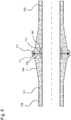
- Fig. 4 shows a cross-sectional view through two plastic pipes 100 and 200 before a connection.
- the plastic pipe 100 includes a pipe wall 101 having a welding surface 105 and a reinforcing portion 103.
- the reinforcing portion 103 serves to transmit tensile forces on the welding surface 105 to the plastic pipe 100 in the longitudinal direction. As a result, bending stresses, which lead to damage of the plastic pipe 100, can be reduced.
- the outer diameter Ra of the plastic pipe 100 continuously increases in the reinforcing portion 103 toward the welding surface 105.
- the inner diameter Ri of the plastic pipe 100 is almost constant in the reinforcing portion 103.
- the outer diameter Ra of the plastic pipe 100 continuously increases, so that a wall thickness gradually increases in this range.
- the outer diameter Ra in a part of the plastic pipe 100 increases linearly.
- the welding surface 105 at one end of the reinforcing portion 103 serves to weld the plastic pipe 100 to another plastic pipe 200.
- On the welding surface there is formed a circular inner welding discharge reservoir 107 for receiving an inwardly pressed welding projection 117.
- the Sch spaaustriebsreservoir 107 runs in a circular manner in the welding surface 105.
- the inner welding discharge reservoir 107 is tapered in cross-section, so that with increasing depth of the Sch spaaustriebsreservoirs 107 in the interior of the reinforcing section 103, the wall thickness of the tube wall 101 is reduced as little as possible.
- the pipe wall 101 has at least the same wall thickness between the inner welding discharge reservoir 107 and an outer side of the reinforcing section 103 as in a section 109 with a constant outer diameter.
- the elements of the plastic tube 200 correspond to those of the plastic tube 100. Both the plastic tube 100 and the plastic tube 200 may be formed by an injection molded part.
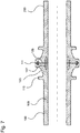
- Fig. 5 shows a cross-sectional view through two plastic pipes 100 and 200 after a connection.
- the welding discharge 117 collects in the inner Sch whoaustriebsreservoir 107 and the outer Sch whoaustriebsreservoir 111 and cools. This prevents sweat expulsion 117 from leaking to the outside.
- the two plastic pipes 100 and 200 are firmly connected to each other at the welding surface 111 by the welding.
- the reinforcing section 103 with continuously increasing outer diameter causes the forces applied to the welding surface 105 to be distributed over the entire tube wall 101 and a stress distribution to be homogenized. Stress peaks, which can lead to cracks in the material, are reduced.
- the reinforcing section 103 thus effects a force flow-optimized outer geometry.
- the outer contour of the plastic pipe 100 is designed by the reinforcing portion 103 such that power flow deflections are largely reduced.
- the depth of the Sch whoaustriebsreservoirs 107 may be, for example 1 mm to 15 mm.
- the depth of the weld discharge reservoir 107 may be in a range of 1 to 3 times the wall thickness of the pipe wall in an unreinforced section.
- the wedge-shaped inner Sch obtainaustriebsreservoir 107 a power flow optimized inner shape and an improved weld geometry are possible.
- An optimized notch shape of the internal Sch obtainaustriebsreservoirs 107 in the groove bottom allows additional voltage reduction and better voltage uniform distribution.
- Fig. 6 shows a cross-sectional view through a tube wall 101 of the plastic tube 100 with lines of a uniform voltage waveform. Unlike the in Fig. 3 As shown, there are no points with stress peaks at which the material tends to crack.
- Fig. 7 shows a further cross-sectional view through the two plastic pipes 100 and 200 after a connection.
- the plastic pipe 100 includes an integrated, circumferential reinforcing ring 115.
- buckling of the plastic pipes 100 can be prevented at high pressures.
- fibers are incorporated, which increase the strength of the reinforcing ring 115. These fibers may be, for example, glass fibers, metal fibers, plastic fibers or carbon fibers.
- Fig. 8 shows different views of a plastic tube 100 with the reinforcing ring 115 and reinforcing ribs 113.
- the reinforcing ribs 113 are integrally formed in the reinforcing portion 103 and extend in a longitudinal direction of the plastic tube 100.
- the outer diameter Ra of the plastic tube 100 increases toward the welding surface 105.
- the increase of the outer diameter Ra may be, for example, continuous or linear.
- the reinforcing ribs 113 formed of plastic may be reinforced by fibers extending, for example, in the direction of the reinforcing ribs.
- a circumferential reinforcing ring 115 is formed in the reinforcing section 103, which revolves on an outer side of the plastic tube 100.
- the reinforcing ring 115 is also reinforced by fibers which extend in the direction of rotation of the reinforcing ring 115.
- the reinforcing ring 115 runs in the region of the reinforcing ribs 113 and connects them together. As a result, the stability of the connecting section can be increased particularly effectively.
- Both the reinforcing ribs 113 and the reinforcing ring 115 are formed integrally in the plastic pipe 100.
- a rib-like configuration on the outside of the weld joint area results in avoiding accumulation of material in manufacturing, such as avoiding voids, reducing cycle time and reducing material usage.
- the invention achieves a force-flow-optimized inner shape as well as a force flow-optimized outer geometry of the plastic pipe.
- a local reduction in component stiffness reduces the (bending) stresses created by operating loads, such as internal pressure or tensile / compressive loading. Certain functions will continue to receive the same, for example, a reservoir for the welding expulsion.
- a load in the Sch dierivs Kunststoff is minimized while maintaining the previous functions with the focus of economical space utilization.
Landscapes
- Engineering & Computer Science (AREA)
- Mechanical Engineering (AREA)
- General Engineering & Computer Science (AREA)
- Chemical & Material Sciences (AREA)
- Combustion & Propulsion (AREA)
- Manufacturing & Machinery (AREA)
- Lining Or Joining Of Plastics Or The Like (AREA)
Description
- Die vorliegende Erfindung betrifft ein Kunststoffrohr, insbesondere für ein Ladeluftrohr in einem Kraftfahrzeug.
- Bei dem Verschweißen von Kunststoffrohren, beispielsweise bei der Automobilfertigung, werden die Enden von Kunststoffrohren erhitzt und aufeinander gepresst, so dass die Enden der Kunststoffrohre miteinander verschmelzen. Der Schweißprozess erfolgt beispielsweise durch Infrarotschweißen, Rotationsschweißen oder Heißgasschweißen, bei dem der Kunststoff in einem definierten Bereich plastifiziert und zusammengefügt wird. Bei diesem Vorgang wird der geschmolzene Kunststoff an der Verbindungsstelle der Kunststoffrohre zur Seite gedrückt und es entsteht ein sogenannter Schweißaustrieb. Anschließend härtet der Schweißaustrieb aus und bildet an der Außen- und/oder Innenseite des Kunststoffrohres eine Wulst. Diese Wulst kann die Strömungseigenschaften im Inneren des Rohres beeinträchtigen. Daher werden an der Kontaktfläche oftmals Aussparungen zum Aufnehmen des Schweißaustriebs angeordnet. Diese Aussparungen - auch als Schweißaustriebreservoire bezeichnet - "kapseln" den Schweißaustrieb ab, so dass störende Einflüsse weitgehend ausgeschlossen werden.
- Die Druckschrift
DE 10 2007 026 826 A1 betrifft ein zweiteiliges Ansaugsystem aus einem thermoplastischen Kunststoff für eine Brennkraftmaschine mit einer Luftzufuhröffnung und wenigstens einer Öffnung zur Abgabe der Luft an eine Brennkraftmaschine. Zur Bildung einer Schweißnaht sind auf den beiden Teilen jeweils umlaufende Kontaktflächen vorgesehen. Der Schweißaustrieb wird in Aufnahmerinnen gesammelt. Allerdings beeinträchtigen die Schweißaustriebreservoire die Stabilität der Verbindung. - Die Druckschrift
US 6,880,593 B1 betrifft ein Kraftstoffeinfüllsystem. Das Kraftstoffeinfüllsystem umfasst ein Rohr dass eine im Querschnitt trapezförmige Schweißfläche zum Verschweißen des Rohres mit einem weiteren Rohr umfasst. - Die Druckschrift
DE 102 16 175 C1 beschreibt ein Rohr bestehend aus einem Innenmantel und einem Außenmantel, wobei der Innenmantel einen Innenraum zur Aufnahme oder Leitung eines Mediums umschließt. - Die Druckschrift "Reibschweißen nach dem Rotations- und Vibrationsverfahren", 4020 Plast-Verarbeiter 34 (1983) Aug., No.8, Speyer, Rhein, Deutschland, beschreibt, dass beim Rotationsschweißen die Plastifizierung durch Reibungsenergie erreicht wird, indem das rotierende obere Formteil durch einen Mitnehmerring mit einer definierten variablen Anpresskraft gegen das untere fest in einer Spannvorrichtung gehaltene Formteil gepresst wird.
- Die Druckschrift "Reibschweißen", 2376 Kunststoffe, 71 (1981), 10, München, Deutschland, beschreibt Beispiele für die Fügeflächengestaltung von Bauteilen, die mittels Rotationsreibschweißen verbunden werden sollen.
- Es ist die der Erfindung zugrundeliegende Aufgabe, ein Kunststoffrohr mit verbesserter Schweißgeometrie anzugeben, die zu einer stabileren Verschweißung führt, ohne dass sich ein Schweißaustrieb an einer Innenseite des Kunststoffrohres bildet.
- Diese Aufgabe wird durch den Gegenstand mit den Merkmalen nach dem unabhängigen Anspruch gelöst. Vorteilhafte Ausführungsformen der Erfindung sind Gegenstand der Figuren, der Beschreibung und der abhängigen Ansprüche.
- Gemäß einem Aspekt der Erfindung wird die Aufgabe durch ein Kunststoffrohr mit einer Rohrwand gelöst, mit einer Schweißfläche zum Verschweißen des Kunststoffrohrs mit einem weiteren Kunststoffrohr, die ein inneres Schweißaustriebsreservoir zum Aufnehmen eines nach Innen gedrückten Schweißaustriebs umfasst; und einem Verstärkungsabschnitt zum Verstärken der Rohrwand im Bereich des Schweißaustriebsreservoirs, in dem ein Außendurchmesser des Kunststoffrohres zur Schweißfläche hin kontinuierlich zunimmt.
- Dadurch wird beispielsweise der technische Vorteil erreicht, dass eine Formoptimierung des Kunststoffrohrs im Schweißnahtbereich erreicht wird, so dass eine Reduktion und Gleichverteilung von Spannungen erfolgt. Dies bewirkt eine Bauteilverbesserung unter schwierigen Einsatzbedingungen, insbesondere bei höheren Belastungen durch einen Innendruck. Zudem können Sauberkeitsanforderungen in Innenbereich des Kunststoffrohrs eingehalten werden.
- Die Kunststoffrohre können im Allgemeinen alle fluidfördemden und geschweißten Kunststoffrohre für beispielsweise Luft, Wasser oder Öl sein, die äußeren oder inneren Belastungen ausgesetzt sind. Das Kunststoffrohr kann insbesondere ein Ladeluftrohr in einem Kraftfahrzeug sein.
- In einer vorteilhaften Ausführungsform des Kunststoffrohres ist der Innendurchmesser des Kunststoffrohrs im Verstärkungsabschnitt nahezu konstant. Insbesondere wenn von werkzeugbedingten Entformungsschrägen abgesehen wird. Dadurch wird beispielsweise der technische Vorteil erreicht, dass sich eine kontinuierliche und glatte Rohrinnenseite ergibt. In einer weiteren vorteilhaften Ausführungsform des Kunststoffrohres läuft das innere Schweißaustriebsreservoir umlaufend, vorzugsweise kreisförmig, in der Schweißfläche herum. Dadurch wird beispielsweise der technische Vorteil erreicht, dass der Schweißaustrieb vollumfänglich aufgenommen werden kann.
- In einer weiteren vorteilhaften Ausführungsform des Kunststoffrohres weist das innere Schweißaustriebsreservoir eine möglichst große Tiefe auf, beispielsweise eine Tiefe von 1 mm bis 15 mm, vorzugsweise von 4 mm bis 10 mm und hochvorzugsweise von 5 mm bis 8 mm. Dadurch wird beispielsweise eine lokale Verringerung der Bauteilsteifigkeit erreicht, welche zu einer geringeren Schweißnahtbelastung führt.Gemäß der Erfindung ist das innere Schweißaustriebsreservoir im Querschnitt keilförmig. Dadurch wird beispielsweise der technische Vorteil erreicht, dass sich die Stabilitätseigenschaften verbessern, da mit zunehmender Tiefe die Aussparung des Schweißaustriebsreservoirs immer schmaler wird.
- In einer weiteren vorteilhaften Ausführungsform des Kunststoffrohres weist die Rohrwand zwischen dem inneren Schweißaustriebsreservoir und einer Außenseite des Verstärkungsabschnittes zumindest die gleiche Wandstärke wie in einem Abschnitt mit konstantem Außendurchmesser auf. Dadurch wird beispielsweise ebenfalls der technische Vorteil erreicht, dass sich die Stabilitätseigenschaften verbessern, da eine bestimmte Wandstärke nicht unterschritten wird.
- In einer weiteren vorteilhaften Ausführungsform des Kunststoffrohres umfasst die Schweißfläche ein äußeres Schweißaustriebsreservoir zum Aufnehmen eines nach Außen gedrückten Schweißaustriebs. Dadurch wird beispielsweise der technische Vorteil erreicht, dass ein Schweißaustrieb nicht auf die Außenseite des Kunststoffrohres gelangt.
- In einer weiteren vorteilhaften Ausführungsform des Kunststoffrohres umfasst der Verstärkungsabschnitt an einer Außenseite Verstärkungsrippen. Dadurch wird beispielsweise der technische Vorteil erreicht, dass sich die Festigkeit der Verbindungsstelle noch weiter verbessert.
- In einer weiteren vorteilhaften Ausführungsform des Kunststoffrohres verlaufen die Verstärkungsrippen in einer Längsrichtung des Kunststoffrohres. Dadurch wird beispielsweise der technische Vorteil erreicht, dass Längskräfte, wie beispielsweise bei hohen Drücken, besonders wirksam aufgenommen werden können.
- In einer weiteren vorteilhaften Ausführungsform des Kunststoffrohres sind die Verstärkungsrippen durch Fasern in Richtung der Verstärkungsrippen verstärkt. Dadurch wird beispielsweise der technische Vorteil erreicht, dass sich die Festigkeit der Verstärkungsrippen verbessert. Gemäß der Erfindung umfasst der Verstärkungsabschnitt einen außen umlaufenden Verstärkungsring. Dadurch wird beispielsweise der technische Vorteil erreicht, dass eine radiale Ausdehnung der Verbindungsstelle bei hohem Druck verringert wird. Gemäß der Erfindung ist der Verstärkungsring in Umlaufrichtung durch Fasern verstärkt. Dadurch wird beispielsweise der technische Vorteil erreicht, dass sich die Festigkeit des Verstärkungsrings verbessert.
- In einer weiteren vorteilhaften Ausführungsform des Kunststoffrohres sind die Verstärkungsrippen mit dem Verstärkungsring verbunden. Dadurch wird beispielsweise der technische Vorteil erreicht, dass die Festigkeit des Kunststoffrohrs im Verbindungsbereich noch weiter verbessert wird.
- In einer weiteren vorteilhaften Ausführungsform des Kunststoffrohres sind die Fasern Glasfasern, Metallfasern, Kunststofffasern oder Kohlenstofffasern. Dadurch wird beispielsweise der technische Vorteil erreicht, dass besonders geeignete Materialien zum Verstärken der jeweiligen Elemente verwendet werden.
- In einer weiteren vorteilhaften Ausführungsform des Kunststoffrohres ist das Kunststoffrohr ein Spritzgussformteil. Dadurch wird beispielsweise der technische Vorteil erreicht, dass sich das Kunststoffrohr auf einfache Weise herstellen lässt.
- In einer weiteren vorteilhaften Ausführungsform des Kunststoffrohres sind die Verstärkungsrippen und/oder der Verstärkungsring aus einem höherfesten Werkstoff gebildet, vorzugsweise aus einem Metall oder einem hochfestem Kunststoff. Ausführungsbeispiele der Erfindung sind in den Zeichnungen dargestellt und werden im Folgenden näher beschrieben.
- Es zeigen:
-
Fig. 1 eine schematische Ansicht einer Verbindung von zwei Kunststoffrohren; und -
Fig. 2 eine schematische Ansicht eines Schweißvorgangs; -
Fig. 3 eine Querschnittsansicht durch zwei Kunststoffrohre vor einer Verbindung; -
Fig. 4 eine Querschnittsansicht durch zwei Kunststoffrohre vor einer Verbindung entlang einer Längsrippe; -
Fig. 5 eine Querschnittsansicht durch zwei Kunststoffrohre nach einer Verbindung entlang einer Längsrippe; -
Fig. 6 eine Querschnittsansicht durch eine Rohrwand eines Kunststoffrohrs mit Linien eines gleichmäßigen Spannungsverlauf entlang einer Längsrippe; -
Fig. 7 eine weitere Querschnittsansicht durch zwei Kunststoffrohre nach einer Verbindung zwischen zwei Längsrippen; und -
Fig. 8 unterschiedliche Ansichten eines Kunststoffrohres mit Verstärkungsring und Verstärkungsrippen. -
Fig. 1 zeigt eine schematische Ansicht einer Verbindung von zwei Kunststoffrohren 100 und 200. Komplexe oder lange Kunststoffrohre werden aufgrund ihrer Geometrie häufig aus zwei oder mehr Teilen hergestellt und anschließend miteinander verschweißt. Dazu werden die Kunststoffrohre 100 und 200 in einem Verbindungsabschnitt 300 erwärmt und aufeinander gesetzt. Für den Schweißprozess werden diverse Techniken eingesetzt, wie beispielsweise Infrarotschweißen, Rotationsschweißen oder Heißgasschweißen, bei denen der Kunststoff in einem definierten Bereich plastifiziert und zusammengefügt wird. -
Fig. 2 zeigt eine schematische Ansicht eines Schweißvorgangs. Die stirnseitige Verschweißung zweier zylindrischer Kunststoffrohre 100 und 200 stellt die einfachste Variante dar. Das senkrechte Ende einer Rohrwand bildet eine Schweißfläche, die erwärmt wird und dadurch einen Schweißbereich bildet. - Nachteilig bei dieser Variante ist, dass flüssiger Kunststoff an der Verbindungsstelle beim Fügeprozess sowohl nach innen als auch nach außen herausgedrückt wird und ein Schweißaustrieb entsteht. Im Inneren des Kunststoffrohres kann der Schweißaustrieb einen erhöhten Strömungsdruckverlust verursachen. Daneben können sich Partikel oder Teile des Schweißaustriebs unkontrolliert ablösen. An der Außenseite entsteht eine ungewollte Kante oder Wulst. Daneben beeinträchtigt ein nach außen gedrückter Schweißaustrieb die ästhetischen Anforderungen.
-
Fig. 3 zeigt eine Querschnittsansicht durch eine Rohrwand zweier Kunststoffrohre 100 und 200 vor einer Verbindung. Zur Aufnahme des Schweißaustriebs weisen diese Schweißaustriebreservoire auf, die durch Aussparungen gebildet werden. Durch die gegenüber der Rohrwand nach Außen versetzte Schweißfläche 121 und die dadurch entstehenden Hebelkräfte wirken bei einer Zugbelastung hohe Spannungen an dem Punkt 400 und dem Punkt 401, so dass an diesen Stellen eine Rissinitiierung beginnt -
Fig. 4 zeigt eine Querschnittsansicht durch zwei Kunststoffrohre 100 und 200 vor einer Verbindung. Das Kunststoffrohr 100 umfasst eine Rohrwand 101 mit einer Schweißfläche 105 und einem Verstärkungsabschnitt 103. Der Verstärkungsabschnitt 103 dient zum Übertragen von Zugkräften an der Schweißfläche 105 auf das Kunststoffrohr 100 in Längsrichtung. Dadurch können Biegespannungen, die zu einer Beschädigung des Kunststoffrohrs 100 führen, verringert werden. Der Außendurchmesser Ra des Kunststoffrohres 100 nimmt in dem Verstärkungsabschnitt 103 zur Schweißfläche 105 hin kontinuierlich zu. - Der Innendurchmesser Ri des Kunststoffrohrs 100 ist in dem Verstärkungsabschnitt 103 nahezu konstant. In dem Verstärkungsabschnitt 103 der Rohrwand 101 nimmt der Außendurchmesser Ra des Kunststoffrohres 100 kontinuierlich zu, so dass sich in diesem Bereich eine Wandstärke graduell erhöht. Beispielsweise nimmt im Verstärkungsabschnitt 103 der Außendurchmesser Ra in einem Teil des Kunststoffrohres 100 linear zu.
- Die Schweißfläche 105 an einem Ende des Verstärkungsabschnitts 103 dient zum Verschweißen des Kunststoffrohrs 100 mit einem weiteren Kunststoffrohr 200. Auf der Schweißfläche ist ein kreisförmiges inneres Schweißaustriebsreservoir 107 zum Aufnehmen eines nach Innen gedrückten Schweißaustriebs 117 gebildet. Das Schweißaustriebsreservoir 107 läuft kreisförmig in der Schweißfläche 105 um.
- Zudem ist das innere Schweißaustriebsreservoir 107 im Querschnitt keilförmig zulaufend, so dass mit zunehmender Tiefe des Schweißaustriebsreservoirs 107 im Inneren des Verstärkungsabschnittes 103 die Wandstärke der Rohrwand 101 möglichst wenig vermindert wird. Die Rohrwand 101 weist zwischen dem inneren Schweißaustriebsreservoir 107 und einer Außenseite des Verstärkungsabschnittes 103 zumindest die gleiche Wandstärke wie in einem Abschnitt 109 mit konstantem Außendurchmesser auf.
- Die Elemente des Kunststoffrohres 200 entsprechen denjenigen des Kunststoffrohres 100. Sowohl das Kunststoffrohr 100 als auch das Kunststoffrohr 200 können durch ein Spritzgussformteil gebildet sein.
-
Fig. 5 zeigt eine Querschnittsansicht durch zwei Kunststoffrohre 100 und 200 nach einer Verbindung. Beim Verbinden der Kunststoffrohre 100 und 200 sammelt sich der Schweißaustrieb 117 in dem inneren Schweißaustriebsreservoir 107 und dem äußeren Schweißaustriebsreservoir 111 und erkaltet. Dadurch wird verhindert, dass Schweißaustrieb 117 nach außen dringt. - Die beiden Kunststoffrohre 100 und 200 sind an der Schweißfläche 111 durch die Schweißung fest miteinander verbunden. Der Verstärkungsabschnitt 103 mit kontinuierlich zunehmendem Außendurchmesser bewirkt, dass die an der Schweißfläche 105 anliegenden Kräfte über die gesamte Rohrwand 101 verteilt werden und sich eine Spannungsverteilung homogenisiert. Spannungsspitzen, die zu Rissen im Material führen können, werden vermindert. Der Verstärkungsabschnitt 103 bewirkt somit eine kraftflussoptimierte Außengeometrie. Zudem wird durch den Verstärkungsabschnitt 103 die Außenkontur des Kunststoffrohres 100 derart gestaltet, dass Kraftflussumlenkungen weitgehend verringert werden.
- Vorteilhaft ist es, das innere Schweißaustriebsreservoir 107 möglichst tief auszuführen, so dass eine Beeinträchtigung der Wandstärke entsprechend gering ist und das Schweißaustriebsreservoir 107 trotzdem eine ausreichende Menge an Schweißaustrieb aufnehmen kann. Die Tiefe des Schweißaustriebsreservoirs 107 kann beispielsweise 1 mm bis 15 mm betragen. Insbesondere kann die Tiefe des Schweißaustriebsreservoirs 107 in einem Bereich von 1 bis 3 mal der Wandstärke der Rohrwand in einem unverstärkten Abschnitt liegen.
- Durch das keilförmige innere Schweißaustriebsreservoir 107 werden eine kraftflussoptimierte Innenform und eine verbesserte Schweißgeometrie ermöglicht. Eine optimierte Kerbform des inneren Schweißaustriebsreservoirs 107 im Nutgrund ermöglicht eine zusätzliche Spannungsreduktion und bessere Spannungsgleichverteilung.
-
Fig. 6 zeigt eine Querschnittsansicht durch eine Rohrwand 101 des Kunststoffrohrs 100 mit Linien eines gleichmäßigen Spannungsverlaufs. Im Gegensatz zu der inFig. 3 gezeigten Form treten keine Punkte mit Spannungsspitzen auf, an denen das Material dazu neigt zu reißen. - Durch den Verstärkungsabschnitt 103 mit kontinuierlich zunehmendem Außendurchmesser wird eine Formoptimierung des Kunststoffrohrs 100 im Schweißnahtbereich erreicht, so dass eine Reduktion und eine Gleichverteilung von Spannungen bei hohen Belastungen erreicht werden.
-
Fig. 7 zeigt eine weitere Querschnittsansicht durch die zwei Kunststoffrohre 100 und 200 nach einer Verbindung. Das Kunststoffrohr 100 umfasst einen integrierten, umlaufenden Verstärkungsring 115. Dadurch kann ein Auswölben der Kunststoffrohre 100 bei hohen Drücken verhindert werden. Zusätzlich sind in den Verstärkungsring 115 Fasern eingearbeitet, die die Festigkeit des Verstärkungsrings 115 erhöhen. Diese Fasern können beispielsweise Glasfasern, Metallfasern, Kunststofffasern oder Kohlenstofffasern sein. -
Fig. 8 zeigt unterschiedliche Ansichten eines Kunststoffrohres 100 mit dem Verstärkungsring 115 und Verstärkungsrippen 113. Die Verstärkungsrippen 113 sind integral in dem Verstärkungsabschnitt 103 gebildet und verlaufen in einer Längsrichtung des Kunststoffrohres 100. In den Verstärkungsrippen 113 nimmt der Außendurchmesser Ra des Kunststoffrohres 100 zur Schweißfläche 105 hin zu. Die Zunahme des Außendurchmessers Ra kann beispielsweise kontinuierlich oder linear sein. - Dadurch können Längskräfte an der Verbindungsstelle der beiden Kunststoffrohre 100 und 200 besonders wirksam aufgenommen werden. Zusätzlich können die aus Kunststoff gebildeten Verstärkungsrippen 113 durch Fasern verstärkt sein, die beispielsweise in Richtung der Verstärkungsrippen verlaufen.
- Zusätzlich zu den Verstärkungsrippen 113 ist im Verstärkungsabschnitt 103 ein umlaufender Verstärkungsring 115 gebildet, der an einer Außenseite des Kunststoffrohres 100 umläuft. Der Verstärkungsring 115 ist ebenfalls durch Fasern verstärkt, die in Umlaufrichtung der Verstärkungsrings 115 verlaufen. Der Verstärkungsring 115 läuft im Bereich der Verstärkungsrippen 113 um und verbindet diese miteinander. Dadurch lässt sich die Stabilität des Verbindungsabschnittes besonders wirkungsvoll erhöhen.
- Sowohl die Verstärkungsrippen 113 als auch der Verstärkungsring 115 sind einstückig in dem Kunststoffrohr 100 ausgebildet. Eine rippenähnliche Gestaltung auf der Außenseite des Schweißverbindungsbereichs führt zu einer Vermeidung von Materialanhäufungen bei der Fertigung, wie beispielsweise zu einer Vermeidung von Lunkern, einer Reduktion einer Zykluszeit und zu einem geringeren Materialeinsatz.
- Durch die Erfindung werden eine kraftflussoptimierte Innenform sowie eine kraftflussoptimierte Außengeometrie des Kunststoffrohres erzielt. Durch eine lokale Verringerung der Bauteilsteifigkeit werden die durch Betriebslasten, wie beispielsweise Innendruck oder Zug-/Druckbelastung, entstehenden (Biege-)Spannungen reduziert. Dabei werden bestimmte Funktionen weiterhin gleichermaßen erhalten, beispielsweise ein Reservoir für den Schweißaustrieb. Eine Belastung im Schweißverbindungsbereich wird bei gleichzeitiger Beibehaltung der bisherigen Funktionen mit dem Focus einer ökonomischen Bauraumausnutzung minimiert.
- Alle in Verbindung mit einzelnen Ausführungsformen der Erfindung erläuterten und gezeigten Merkmale können in unterschiedlicher Kombination in dem erfindungsgemäßen Gegenstand vorgesehen sein, um gleichzeitig deren vorteilhafte Wirkungen zu realisieren.
- Der Schutzbereich der vorliegenden Erfindung ist durch die Ansprüche gegeben und wird durch die in der Beschreibung erläuterten oder den Figuren gezeigten Merkmale nicht beschränkt.
-
- 100
- Kunststoffrohr
- 101
- Rohrwand
- 103
- Verstärkungsabschnitt
- 105
- Schweißfläche
- 107
- Inneres Schweißaustriebsreservoir
- 109
- Abschnitt mit konstantem Außendurchmesser
- 111
- Äußeres Schweißaustriebsreservoir
- 113
- Verstärkungsrippen
- 115
- Verstärkungsring
- 117
- Schweißaustrieb
- 119
- Schweißaustrieb
- 121
- Schweißfläche
- 200
- Kunststoffrohr
- 300
- Verbindungsbereich
- 400
- Stelle höherer Spannung
- 401
- Stelle höherer Spannung
Claims (12)
- Kunststoffrohr (100) mit einer Rohrwand (101), gekennzeichnet durch:eine Schweißfläche (105) zum Verschweißen des Kunststoffrohrs (100) mit einem weiteren Kunststoffrohr (200), die ein inneres, im Querschnitt keilförmiges Schweißaustriebsreservoir (107) zum Aufnehmen eines nach Innen gedrückten Schweißaustriebs (117) umfasst; undeinen Verstärkungsabschnitt (103) zum Verstärken der Rohrwand (101) im Bereich des Schweißaustriebsreservoirs (107), in dem ein Außendurchmesser (Ra) des Kunststoffrohres (100) zur Schweißfläche hin zunimmt,wobei der Verstärkungsabschnitt (103) einen außen umlaufenden Verstärkungsring (115) umfasst, wobei der Verstärkungsring (115) in Umlaufrichtung durch Fasern verstärkt ist.
- Kunststoffrohr (100) nach Anspruch 1, wobei der Innendurchmesser (Ri) des Kunststoffrohrs (100) im Verstärkungsabschnitt (103) konstant ist.
- Kunststoffrohr (100) nach einem der vorangehenden Ansprüche, wobei das innere Schweißaustriebsreservoir (107) umlaufend in der Schweißfläche (105) gebildet ist.
- Kunststoffrohr (100) nach einem der vorangehenden Ansprüche, wobei das innere Schweißaustriebsreservoir (107) eine Tiefe von 1 mm bis 15 mm, vorzugsweise von 4 mm bis 10 mm und hochvorzugsweise von 5 mm bis 8 mm aufweist.
- Kunststoffrohr (100) nach einem der vorangehenden Ansprüche, wobei die Rohrwand (101) zwischen dem inneren Schweißaustriebsreservoir (107) und einer Außenseite des Verstärkungsabschnittes (103) zumindest die gleiche Wandstärke wie in einem Abschnitt (109) mit konstantem Außendurchmesser aufweist.
- Kunststoffrohr (100) nach einem der vorangehenden Ansprüche, wobei die Schweißfläche (105) ein äußeres Schweißaustriebsreservoir (111) zum Aufnehmen eines nach Außen gedrückten Schweißaustriebs (119) umfasst.
- Kunststoffrohr (100) nach einem der vorangehenden Ansprüche, wobei der Verstärkungsabschnitt (103) an einer Außenseite Verstärkungsrippen (113) umfasst.
- Kunststoffrohr (100) nach Anspruch 7, wobei die Verstärkungsrippen (113) in einer Längsrichtung des Kunststoffrohres (100) verlaufen.
- Kunststoffrohr (100) nach Anspruch 7 oder 8, wobei die Verstärkungsrippen (113) durch Fasern in Richtung der Verstärkungsrippen verstärkt sind.
- Kunststoffrohr (100) nach Anspruch 7, 8 oder 9, wobei die Verstärkungsrippen (113) mit dem Verstärkungsring (115) verbunden sind.
- Kunststoffrohr (100) nach Anspruch 1 oder 9, wobei die Fasern Glasfasern, Metallfasern, Kunststofffasern oder Kohlenstofffasern sind.
- Kunststoffrohr (100) nach einem der vorangehenden Ansprüche, wobei das Kunststoffrohr ein Spritzgussformteil ist.
Applications Claiming Priority (1)
| Application Number | Priority Date | Filing Date | Title |
|---|---|---|---|
| DE102012110729.7A DE102012110729A1 (de) | 2012-11-09 | 2012-11-09 | Kunststoffrohr |
Publications (2)
| Publication Number | Publication Date |
|---|---|
| EP2730829A1 EP2730829A1 (de) | 2014-05-14 |
| EP2730829B1 true EP2730829B1 (de) | 2017-09-06 |
Family
ID=48874797
Family Applications (1)
| Application Number | Title | Priority Date | Filing Date |
|---|---|---|---|
| EP13176951.5A Active EP2730829B1 (de) | 2012-11-09 | 2013-07-18 | Kunststoffrohr |
Country Status (2)
| Country | Link |
|---|---|
| EP (1) | EP2730829B1 (de) |
| DE (1) | DE102012110729A1 (de) |
Families Citing this family (3)
| Publication number | Priority date | Publication date | Assignee | Title |
|---|---|---|---|---|
| AT517312A1 (de) * | 2015-06-08 | 2016-12-15 | Jansen Ag | Rohrverbindung mit zumindest zwei Rohren mit Rohrwandungen aus einem Kunststoff-Monomaterial |
| KR102620420B1 (ko) * | 2019-09-24 | 2024-01-03 | 다이킨 고교 가부시키가이샤 | 용착체 |
| CN111059394A (zh) * | 2019-11-18 | 2020-04-24 | 华创天元实业发展有限责任公司 | 一种耐磨钢丝网管对接焊管件 |
Family Cites Families (10)
| Publication number | Priority date | Publication date | Assignee | Title |
|---|---|---|---|---|
| GB2279035B (en) * | 1991-01-22 | 1995-06-07 | Rover Group | Fabrication of an internal combustion engine inlet manifold |
| DE10038493C1 (de) * | 2000-08-08 | 2001-10-18 | Ritz Reinert Gmbh | Übergangsstück einer Übergangs-Rohrverbindung |
| DE20113496U1 (de) * | 2001-08-14 | 2001-10-18 | Dr.Ing.H.C. F. Porsche Ag, 70435 Stuttgart | Sauganlage für eine Brennkraftmaschine |
| DE10216175C1 (de) * | 2002-04-12 | 2003-07-24 | Stiebel Eltron Gmbh & Co Kg | Bauteil, insbesondere Behälter oder Rohr, und Verfahren zur Herstellung eines Behälters |
| US6880593B1 (en) * | 2003-12-10 | 2005-04-19 | Dayco Products, Llc | Fuel fill system |
| JP2005337108A (ja) * | 2004-05-26 | 2005-12-08 | Toyota Boshoku Corp | サージタンクの接合構造及びサージタンク並びにインテークマニホールド |
| DE102006010815A1 (de) * | 2006-03-07 | 2007-09-13 | Geiger Technik Gesellschaft mit beschränkter Haftung | Gehäuse aus thermoplastischem Kunststoff und Verfahren zu seiner Herstellung |
| DE202006011026U1 (de) * | 2006-07-14 | 2007-12-06 | Mann + Hummel Gmbh | Ansaugeinrichtung für eine Brennkraftmaschine |
| DE102007026826A1 (de) | 2007-06-06 | 2008-12-11 | Mann + Hummel Gmbh | Ansaugsystem |
| DE102010027182A1 (de) * | 2010-07-14 | 2012-01-19 | Thyssenkrupp Tailored Blanks Gmbh | Rohrförmiges Bauteil aus miteinander im Stumpfstoß verschweißten Metallrohren unterschiedlicher Wandstärke und Verfahren zu dessen Herstellung |
-
2012
- 2012-11-09 DE DE102012110729.7A patent/DE102012110729A1/de not_active Withdrawn
-
2013
- 2013-07-18 EP EP13176951.5A patent/EP2730829B1/de active Active
Non-Patent Citations (1)
| Title |
|---|
| None * |
Also Published As
| Publication number | Publication date |
|---|---|
| EP2730829A1 (de) | 2014-05-14 |
| DE102012110729A1 (de) | 2014-05-15 |
Similar Documents
| Publication | Publication Date | Title |
|---|---|---|
| EP2494179B1 (de) | Abgaswärmetauscher | |
| EP2184525B1 (de) | Rohrverbindung mit einem Rohr und Verfahren zur Herstellung eines Verbindungsabschnitts einer Rohrverbindung | |
| DE102014004157B4 (de) | Verfahren zur Herstellung von Lasteinleitungs-Flanschen an faserverstärkten Hohlprofilen mit thermoplastischer Matrix | |
| DE102012211866A1 (de) | Zylinderlaufbuchse | |
| EP3369544B1 (de) | Hohlprofil-verbundtechnologie | |
| EP3114345B1 (de) | Schalldämpfer | |
| WO2009112191A1 (de) | Kraftstoffverteilerbaugruppe | |
| EP2730829A1 (de) | Kunststoffrohr | |
| EP3448653B1 (de) | Einfüllrohr für einen kraftstofftank | |
| EP2611595B1 (de) | Luftansaugrohr | |
| DE102012018788B4 (de) | Verfahren zur Herstellung eines Verbundbauteils | |
| EP1419001B1 (de) | Gehäuse | |
| DE102010030484A1 (de) | Modulares Leichtbau-Strebenelement | |
| WO2019180171A1 (de) | Hybridrohr mit rohrbund und verschleissring und verfahren zu dessen herstellung | |
| EP1736668A2 (de) | Stator für eine Exzenterschneckenpumpe und Verfahren zu seiner Herstellung | |
| DE102010052578A1 (de) | Kolben für eine Brennkraftmaschine | |
| EP1782876B1 (de) | Filter-Wärmeübertrager-Kombination für Flüssigkeiten, insbesondere Schmieröl eines Kraftfahrzeug-Verbrennungsmotors | |
| EP1890926A1 (de) | Zahnstangenlenkung mit unterschiedlichen wandstärken | |
| DE102004019698B4 (de) | Gewendeltes Rohrelement | |
| DE102012205496A1 (de) | Thermisch isoliertes Leitungselement und Verfahren zu dessen Herstellung | |
| EP1728617A2 (de) | Verfahren zur Herstellung einer Rohrendsteckmuffe sowie Sickeneinsatz für eine Rohrendsteckmuffe | |
| EP3822062B1 (de) | Kunststofftank und verfahren zur herstellung eines kunststofftanks | |
| DE102004038138A1 (de) | Verfahren zur Herstellung eines hybriden Rohres und derartig hergestelltes hybrides Rohr für eine Kraftfahrzeugkarosserie | |
| DE102006034865B4 (de) | Verfahren zum Verbinden einer Flanschplatte mit einem abgasführenden Rohr und Flansch-Rohr-Verbindung | |
| EP3000578B1 (de) | Verfahren zum herstellen einer anordnung mit einem rohrkörper |
Legal Events
| Date | Code | Title | Description |
|---|---|---|---|
| PUAI | Public reference made under article 153(3) epc to a published international application that has entered the european phase |
Free format text: ORIGINAL CODE: 0009012 |
|
| 17P | Request for examination filed |
Effective date: 20130718 |
|
| AK | Designated contracting states |
Kind code of ref document: A1 Designated state(s): AL AT BE BG CH CY CZ DE DK EE ES FI FR GB GR HR HU IE IS IT LI LT LU LV MC MK MT NL NO PL PT RO RS SE SI SK SM TR |
|
| AX | Request for extension of the european patent |
Extension state: BA ME |
|
| R17P | Request for examination filed (corrected) |
Effective date: 20140513 |
|
| RBV | Designated contracting states (corrected) |
Designated state(s): AL AT BE BG CH CY CZ DE DK EE ES FI FR GB GR HR HU IE IS IT LI LT LU LV MC MK MT NL NO PL PT RO RS SE SI SK SM TR |
|
| 17Q | First examination report despatched |
Effective date: 20160512 |
|
| GRAP | Despatch of communication of intention to grant a patent |
Free format text: ORIGINAL CODE: EPIDOSNIGR1 |
|
| STAA | Information on the status of an ep patent application or granted ep patent |
Free format text: STATUS: GRANT OF PATENT IS INTENDED |
|
| RIC1 | Information provided on ipc code assigned before grant |
Ipc: B29C 65/10 20060101ALN20170301BHEP Ipc: B29C 65/06 20060101ALN20170301BHEP Ipc: F16L 47/14 20060101ALI20170301BHEP Ipc: F16L 47/02 20060101AFI20170301BHEP Ipc: B29C 65/02 20060101ALN20170301BHEP Ipc: B29C 65/14 20060101ALN20170301BHEP |
|
| INTG | Intention to grant announced |
Effective date: 20170315 |
|
| GRAS | Grant fee paid |
Free format text: ORIGINAL CODE: EPIDOSNIGR3 |
|
| GRAA | (expected) grant |
Free format text: ORIGINAL CODE: 0009210 |
|
| STAA | Information on the status of an ep patent application or granted ep patent |
Free format text: STATUS: THE PATENT HAS BEEN GRANTED |
|
| AK | Designated contracting states |
Kind code of ref document: B1 Designated state(s): AL AT BE BG CH CY CZ DE DK EE ES FI FR GB GR HR HU IE IS IT LI LT LU LV MC MK MT NL NO PL PT RO RS SE SI SK SM TR |
|
| REG | Reference to a national code |
Ref country code: GB Ref legal event code: FG4D Free format text: NOT ENGLISH |
|
| REG | Reference to a national code |
Ref country code: CH Ref legal event code: EP Ref country code: AT Ref legal event code: REF Ref document number: 926267 Country of ref document: AT Kind code of ref document: T Effective date: 20170915 |
|
| REG | Reference to a national code |
Ref country code: IE Ref legal event code: FG4D Free format text: LANGUAGE OF EP DOCUMENT: GERMAN |
|
| REG | Reference to a national code |
Ref country code: DE Ref legal event code: R096 Ref document number: 502013008257 Country of ref document: DE |
|
| REG | Reference to a national code |
Ref country code: NL Ref legal event code: MP Effective date: 20170906 |
|
| REG | Reference to a national code |
Ref country code: LT Ref legal event code: MG4D |
|
| PG25 | Lapsed in a contracting state [announced via postgrant information from national office to epo] |
Ref country code: NO Free format text: LAPSE BECAUSE OF FAILURE TO SUBMIT A TRANSLATION OF THE DESCRIPTION OR TO PAY THE FEE WITHIN THE PRESCRIBED TIME-LIMIT Effective date: 20171206 Ref country code: LT Free format text: LAPSE BECAUSE OF FAILURE TO SUBMIT A TRANSLATION OF THE DESCRIPTION OR TO PAY THE FEE WITHIN THE PRESCRIBED TIME-LIMIT Effective date: 20170906 Ref country code: HR Free format text: LAPSE BECAUSE OF FAILURE TO SUBMIT A TRANSLATION OF THE DESCRIPTION OR TO PAY THE FEE WITHIN THE PRESCRIBED TIME-LIMIT Effective date: 20170906 Ref country code: FI Free format text: LAPSE BECAUSE OF FAILURE TO SUBMIT A TRANSLATION OF THE DESCRIPTION OR TO PAY THE FEE WITHIN THE PRESCRIBED TIME-LIMIT Effective date: 20170906 Ref country code: SE Free format text: LAPSE BECAUSE OF FAILURE TO SUBMIT A TRANSLATION OF THE DESCRIPTION OR TO PAY THE FEE WITHIN THE PRESCRIBED TIME-LIMIT Effective date: 20170906 |
|
| PG25 | Lapsed in a contracting state [announced via postgrant information from national office to epo] |
Ref country code: ES Free format text: LAPSE BECAUSE OF FAILURE TO SUBMIT A TRANSLATION OF THE DESCRIPTION OR TO PAY THE FEE WITHIN THE PRESCRIBED TIME-LIMIT Effective date: 20170906 Ref country code: LV Free format text: LAPSE BECAUSE OF FAILURE TO SUBMIT A TRANSLATION OF THE DESCRIPTION OR TO PAY THE FEE WITHIN THE PRESCRIBED TIME-LIMIT Effective date: 20170906 Ref country code: RS Free format text: LAPSE BECAUSE OF FAILURE TO SUBMIT A TRANSLATION OF THE DESCRIPTION OR TO PAY THE FEE WITHIN THE PRESCRIBED TIME-LIMIT Effective date: 20170906 Ref country code: GR Free format text: LAPSE BECAUSE OF FAILURE TO SUBMIT A TRANSLATION OF THE DESCRIPTION OR TO PAY THE FEE WITHIN THE PRESCRIBED TIME-LIMIT Effective date: 20171207 Ref country code: BG Free format text: LAPSE BECAUSE OF FAILURE TO SUBMIT A TRANSLATION OF THE DESCRIPTION OR TO PAY THE FEE WITHIN THE PRESCRIBED TIME-LIMIT Effective date: 20171206 |
|
| PG25 | Lapsed in a contracting state [announced via postgrant information from national office to epo] |
Ref country code: NL Free format text: LAPSE BECAUSE OF FAILURE TO SUBMIT A TRANSLATION OF THE DESCRIPTION OR TO PAY THE FEE WITHIN THE PRESCRIBED TIME-LIMIT Effective date: 20170906 |
|
| PG25 | Lapsed in a contracting state [announced via postgrant information from national office to epo] |
Ref country code: RO Free format text: LAPSE BECAUSE OF FAILURE TO SUBMIT A TRANSLATION OF THE DESCRIPTION OR TO PAY THE FEE WITHIN THE PRESCRIBED TIME-LIMIT Effective date: 20170906 Ref country code: CZ Free format text: LAPSE BECAUSE OF FAILURE TO SUBMIT A TRANSLATION OF THE DESCRIPTION OR TO PAY THE FEE WITHIN THE PRESCRIBED TIME-LIMIT Effective date: 20170906 Ref country code: PL Free format text: LAPSE BECAUSE OF FAILURE TO SUBMIT A TRANSLATION OF THE DESCRIPTION OR TO PAY THE FEE WITHIN THE PRESCRIBED TIME-LIMIT Effective date: 20170906 |
|
| PG25 | Lapsed in a contracting state [announced via postgrant information from national office to epo] |
Ref country code: SM Free format text: LAPSE BECAUSE OF FAILURE TO SUBMIT A TRANSLATION OF THE DESCRIPTION OR TO PAY THE FEE WITHIN THE PRESCRIBED TIME-LIMIT Effective date: 20170906 Ref country code: SK Free format text: LAPSE BECAUSE OF FAILURE TO SUBMIT A TRANSLATION OF THE DESCRIPTION OR TO PAY THE FEE WITHIN THE PRESCRIBED TIME-LIMIT Effective date: 20170906 Ref country code: IS Free format text: LAPSE BECAUSE OF FAILURE TO SUBMIT A TRANSLATION OF THE DESCRIPTION OR TO PAY THE FEE WITHIN THE PRESCRIBED TIME-LIMIT Effective date: 20180106 Ref country code: EE Free format text: LAPSE BECAUSE OF FAILURE TO SUBMIT A TRANSLATION OF THE DESCRIPTION OR TO PAY THE FEE WITHIN THE PRESCRIBED TIME-LIMIT Effective date: 20170906 |
|
| REG | Reference to a national code |
Ref country code: DE Ref legal event code: R097 Ref document number: 502013008257 Country of ref document: DE |
|
| PLBE | No opposition filed within time limit |
Free format text: ORIGINAL CODE: 0009261 |
|
| STAA | Information on the status of an ep patent application or granted ep patent |
Free format text: STATUS: NO OPPOSITION FILED WITHIN TIME LIMIT |
|
| REG | Reference to a national code |
Ref country code: FR Ref legal event code: PLFP Year of fee payment: 6 |
|
| PG25 | Lapsed in a contracting state [announced via postgrant information from national office to epo] |
Ref country code: DK Free format text: LAPSE BECAUSE OF FAILURE TO SUBMIT A TRANSLATION OF THE DESCRIPTION OR TO PAY THE FEE WITHIN THE PRESCRIBED TIME-LIMIT Effective date: 20170906 |
|
| 26N | No opposition filed |
Effective date: 20180607 |
|
| PG25 | Lapsed in a contracting state [announced via postgrant information from national office to epo] |
Ref country code: SI Free format text: LAPSE BECAUSE OF FAILURE TO SUBMIT A TRANSLATION OF THE DESCRIPTION OR TO PAY THE FEE WITHIN THE PRESCRIBED TIME-LIMIT Effective date: 20170906 |
|
| PG25 | Lapsed in a contracting state [announced via postgrant information from national office to epo] |
Ref country code: MT Free format text: LAPSE BECAUSE OF FAILURE TO SUBMIT A TRANSLATION OF THE DESCRIPTION OR TO PAY THE FEE WITHIN THE PRESCRIBED TIME-LIMIT Effective date: 20170906 |
|
| REG | Reference to a national code |
Ref country code: CH Ref legal event code: PL |
|
| PG25 | Lapsed in a contracting state [announced via postgrant information from national office to epo] |
Ref country code: MC Free format text: LAPSE BECAUSE OF FAILURE TO SUBMIT A TRANSLATION OF THE DESCRIPTION OR TO PAY THE FEE WITHIN THE PRESCRIBED TIME-LIMIT Effective date: 20170906 Ref country code: LU Free format text: LAPSE BECAUSE OF NON-PAYMENT OF DUE FEES Effective date: 20180718 |
|
| REG | Reference to a national code |
Ref country code: BE Ref legal event code: MM Effective date: 20180731 |
|
| REG | Reference to a national code |
Ref country code: IE Ref legal event code: MM4A |
|
| PG25 | Lapsed in a contracting state [announced via postgrant information from national office to epo] |
Ref country code: IE Free format text: LAPSE BECAUSE OF NON-PAYMENT OF DUE FEES Effective date: 20180718 Ref country code: CH Free format text: LAPSE BECAUSE OF NON-PAYMENT OF DUE FEES Effective date: 20180731 Ref country code: LI Free format text: LAPSE BECAUSE OF NON-PAYMENT OF DUE FEES Effective date: 20180731 |
|
| PG25 | Lapsed in a contracting state [announced via postgrant information from national office to epo] |
Ref country code: BE Free format text: LAPSE BECAUSE OF NON-PAYMENT OF DUE FEES Effective date: 20180731 |
|
| REG | Reference to a national code |
Ref country code: AT Ref legal event code: MM01 Ref document number: 926267 Country of ref document: AT Kind code of ref document: T Effective date: 20180718 |
|
| PG25 | Lapsed in a contracting state [announced via postgrant information from national office to epo] |
Ref country code: AT Free format text: LAPSE BECAUSE OF NON-PAYMENT OF DUE FEES Effective date: 20180718 |
|
| PG25 | Lapsed in a contracting state [announced via postgrant information from national office to epo] |
Ref country code: TR Free format text: LAPSE BECAUSE OF FAILURE TO SUBMIT A TRANSLATION OF THE DESCRIPTION OR TO PAY THE FEE WITHIN THE PRESCRIBED TIME-LIMIT Effective date: 20170906 |
|
| PG25 | Lapsed in a contracting state [announced via postgrant information from national office to epo] |
Ref country code: PT Free format text: LAPSE BECAUSE OF FAILURE TO SUBMIT A TRANSLATION OF THE DESCRIPTION OR TO PAY THE FEE WITHIN THE PRESCRIBED TIME-LIMIT Effective date: 20170906 Ref country code: HU Free format text: LAPSE BECAUSE OF FAILURE TO SUBMIT A TRANSLATION OF THE DESCRIPTION OR TO PAY THE FEE WITHIN THE PRESCRIBED TIME-LIMIT; INVALID AB INITIO Effective date: 20130718 |
|
| PG25 | Lapsed in a contracting state [announced via postgrant information from national office to epo] |
Ref country code: CY Free format text: LAPSE BECAUSE OF FAILURE TO SUBMIT A TRANSLATION OF THE DESCRIPTION OR TO PAY THE FEE WITHIN THE PRESCRIBED TIME-LIMIT Effective date: 20170906 Ref country code: MK Free format text: LAPSE BECAUSE OF NON-PAYMENT OF DUE FEES Effective date: 20170906 |
|
| PG25 | Lapsed in a contracting state [announced via postgrant information from national office to epo] |
Ref country code: AL Free format text: LAPSE BECAUSE OF FAILURE TO SUBMIT A TRANSLATION OF THE DESCRIPTION OR TO PAY THE FEE WITHIN THE PRESCRIBED TIME-LIMIT Effective date: 20170906 |
|
| PGFP | Annual fee paid to national office [announced via postgrant information from national office to epo] |
Ref country code: GB Payment date: 20200724 Year of fee payment: 8 |
|
| GBPC | Gb: european patent ceased through non-payment of renewal fee |
Effective date: 20210718 |
|
| PG25 | Lapsed in a contracting state [announced via postgrant information from national office to epo] |
Ref country code: GB Free format text: LAPSE BECAUSE OF NON-PAYMENT OF DUE FEES Effective date: 20210718 |
|
| REG | Reference to a national code |
Ref country code: DE Ref legal event code: R082 Ref document number: 502013008257 Country of ref document: DE |
|
| P01 | Opt-out of the competence of the unified patent court (upc) registered |
Effective date: 20230515 |
|
| PGFP | Annual fee paid to national office [announced via postgrant information from national office to epo] |
Ref country code: DE Payment date: 20240719 Year of fee payment: 12 |
|
| PGFP | Annual fee paid to national office [announced via postgrant information from national office to epo] |
Ref country code: FR Payment date: 20240724 Year of fee payment: 12 |
|
| PGFP | Annual fee paid to national office [announced via postgrant information from national office to epo] |
Ref country code: IT Payment date: 20240731 Year of fee payment: 12 |
|
| REG | Reference to a national code |
Ref country code: DE Ref legal event code: R119 Ref document number: 502013008257 Country of ref document: DE |
|
| PG25 | Lapsed in a contracting state [announced via postgrant information from national office to epo] |
Ref country code: DE Free format text: LAPSE BECAUSE OF NON-PAYMENT OF DUE FEES Effective date: 20260203 |
|
| PG25 | Lapsed in a contracting state [announced via postgrant information from national office to epo] |
Ref country code: FR Free format text: LAPSE BECAUSE OF NON-PAYMENT OF DUE FEES Effective date: 20250731 |