EP2728972B2 - Steuerung des Betriebs von Lichtquellen - Google Patents
Steuerung des Betriebs von Lichtquellen Download PDFInfo
- Publication number
- EP2728972B2 EP2728972B2 EP12190767.9A EP12190767A EP2728972B2 EP 2728972 B2 EP2728972 B2 EP 2728972B2 EP 12190767 A EP12190767 A EP 12190767A EP 2728972 B2 EP2728972 B2 EP 2728972B2
- Authority
- EP
- European Patent Office
- Prior art keywords
- light source
- light
- light intensity
- control signal
- input control
- Prior art date
- Legal status (The legal status is an assumption and is not a legal conclusion. Google has not performed a legal analysis and makes no representation as to the accuracy of the status listed.)
- Active
Links
Images


Classifications
-
- H—ELECTRICITY
- H05—ELECTRIC TECHNIQUES NOT OTHERWISE PROVIDED FOR
- H05B—ELECTRIC HEATING; ELECTRIC LIGHT SOURCES NOT OTHERWISE PROVIDED FOR; CIRCUIT ARRANGEMENTS FOR ELECTRIC LIGHT SOURCES, IN GENERAL
- H05B45/00—Circuit arrangements for operating light-emitting diodes [LED]
- H05B45/20—Controlling the colour of the light
-
- H—ELECTRICITY
- H05—ELECTRIC TECHNIQUES NOT OTHERWISE PROVIDED FOR
- H05B—ELECTRIC HEATING; ELECTRIC LIGHT SOURCES NOT OTHERWISE PROVIDED FOR; CIRCUIT ARRANGEMENTS FOR ELECTRIC LIGHT SOURCES, IN GENERAL
- H05B47/00—Circuit arrangements for operating light sources in general, i.e. where the type of light source is not relevant
- H05B47/10—Controlling the light source
- H05B47/175—Controlling the light source by remote control
- H05B47/185—Controlling the light source by remote control via power line carrier transmission
-
- H—ELECTRICITY
- H05—ELECTRIC TECHNIQUES NOT OTHERWISE PROVIDED FOR
- H05B—ELECTRIC HEATING; ELECTRIC LIGHT SOURCES NOT OTHERWISE PROVIDED FOR; CIRCUIT ARRANGEMENTS FOR ELECTRIC LIGHT SOURCES, IN GENERAL
- H05B47/00—Circuit arrangements for operating light sources in general, i.e. where the type of light source is not relevant
- H05B47/10—Controlling the light source
- H05B47/165—Controlling the light source following a pre-assigned programmed sequence; Logic control [LC]
Definitions
- the invention relates to control of two or more light sources.
- the invention relates to an apparatus and to a computer program for controlling operation of two or more light sources, such as two or more light emitting diodes (LEDs), two or more fluorescent lamps, two or more high-intensity discharge (HID) lamps, two or more incandescent lamps, etc.
- LEDs light emitting diodes
- HID high-intensity discharge
- FIG. 1 schematically illustrates an exemplifying conceptual switching arrangement 100 known in the art.
- the switching arrangement 100 comprises a switch unit 110, a controller 120 and a light source 140.
- the switch unit 110 comprises a user-operable push button or a corresponding arrangement configured to provide an input control signal to the controller 120 in response to the push button being pushed, the input control signal having a duration essentially corresponding to the duration of the push button being pushed. Consequently, the controller 120 is configured to control the light source 140 in dependence of the duration of the input control signal such that a short input control signal results in switching the light source 140 on or off, whereas a long input control signal results in changing the light intensity provided by the light source 140, thereby providing a dimming functionality.
- a short input control signal received during the off state of the light source 140 results in switching the light source 140 on, while a short drive signal received during the on state results in switching the light source 140 off.
- a long input control signal results in increasing the light intensity provided by the light source 140.
- the most recent input control signal was a long input control signal for increasing the light intensity
- a long input control signal results in decreasing the light intensity provided by the light source 140.
- a long input control signal received when the light source 140 is in the off state may result in switching the light source 140 on.
- the exemplifying arrangement 100 as described above enables the control of the on/off state of the light element 140 and the intensity of light provided by the light element 140 by a single switch operated by a single push-button, it would be desirable to also enable different and/or more versatile adjustment of characteristics of light provided by the light element 140 in order to enable better adaptation to variations in ambient light conditions and different usages of a space the light element 140 is employed to illuminate.
- Known solutions for providing further or alternative functions typically require further components to be introduced to the arrangement 100 and/or a significant modification of the arrangement 100, resulting in an arrangement that is typically more complex to construct and more expensive to manufacture.
- a prior art document EP 2 219 418 A2 discloses a LED illumination device, with determination means that determines light amounts of the light-emitting diodes of the illumination light source, corresponding to an operation input received at operation input receiving means, so that a color temperature and a light amount of the illumination light increase and decrease in conjunction with each other. The light color and the illumination intensity of the illumination light can be adjusted with the characteristic proximate to an incandescent lamp.
- a prior art document WO 2011/107280 A2 discloses an operating device for a light-emitting diode that comprises an interface connection for capturing probe signals or potentiometer control signals. An internal voltage source feeds the inlet connection. The probe signals are produced by a probe that short-circuits or disconnects both connections of the interface during the actuation thereof.
- an apparatus for controlling operation of a first light source of a first color and a second light source of a second color comprises an input portion configured to receive an input control signal having a user-controllable duration and a control portion configured to switch, in response to a single input control signal having the overall duration not exceeding a first predetermined threshold, the first and second light sources on or off, wherein the control portion is further configured to change characteristics of light provided by the first and second light sources in response to the duration of an input control signal exceeding a second predetermined threshold that is no smaller than the first predetermined threshold, the change in characteristics being dependent on duration of the input control signal and the change comprising adjustment of the ratio between the light intensities of the first light source and the second light source.
- the change further comprises adjustment of the combined light intensity of the first light source and the second light source such that the ratio between the light intensity of the first light source and the second light source remains essentially constant.
- the adjustment of combined light intensity is continued until termination of the input control signal or until reaching a maximum or a minimum combined light intensity of the first and the second light sources.
- the change comprises adjustment of the ratio between the light intensities of the first light source and the second light source in accordance with a first predetermined rule in response to the input control signal continuing after a predetermined period of time after reaching said maximum combined light intensity of the first and the second light sources has elapsed.
- a second apparatus for controlling operation of a first light source of a first color and a second light source of a second color.
- the second apparatus comprises at least one processor and at least one memory including computer program code for one or more programs.
- the at least one memory and the computer program code are configured to, with the at least one processor, cause the apparatus, at least, to
- a computer program for controlling operation of a first light source of a first color and a second light source of a second color comprises one or more sequences of one or more instructions which, when executed by one or more processors, cause an apparatus, at least, to
- the computer program may be embodied on a volatile or a non-volatile computer-readable record medium, for example as a computer program product comprising at least one computer readable non-transitory medium having program code stored thereon, the program code, which when executed by an apparatus, causes the apparatus at least to perform the operations described hereinbefore for the computer program in accordance with the third aspect of the invention.
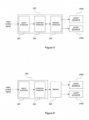
- Figure 2 schematically illustrates an exemplifying conceptual arrangement 200 comprising a switch unit 210, a controller 220 and two or more light sources 240.
- the one or more light sources 240 are depicted as comprising a first light source 240a and a second light source 240b, although the two or more light sources 240 may comprise further light sources.
- the two or more light sources 240 may be arranged into one or more light elements, such that each light element comprises one or more of the two or more light sources 240.
- the arrangement 200 presents a logical architecture, and the elements thereof may be provided as units or portions of a single apparatus or units or portions of one or more apparatuses.
- the switch unit 210 and the controller 220 are logical entities which may be implemented in one or more apparatuses, with the two or more light sources 240 being connectable to the apparatus of the one or more apparatuses comprising the controller 220 or a portion thereof. Examples in this regard are described in the following.
- all elements may be implemented in a single apparatus, the single apparatus hence comprising the switch unit 210, the controller 220 and an arrangement for connecting the two or more light sources 240 thereto.
- a single apparatus hence comprising the switch unit 210, the controller 220 and an arrangement for connecting the two or more light sources 240 thereto.
- Such an apparatus may be referred to e.g. as a switch apparatus, as a control apparatus, as a switch control apparatus, as a driver apparatus, etc.
- the switch unit 210 may be implemented in a first apparatus and the controller 220 may be implemented in a second apparatus together with an arrangement for connecting the two or more light sources 240 thereto.
- the second apparatus may be referred to e.g. as a control apparatus, as a switch control apparatus, as a driver apparatus, etc.
- the switch unit 210 may be implemented in a first apparatus, a first portion of the controller 220 may be implemented in a second apparatus, and a second portion of the controller 220 may be implemented in a third apparatus together with an arrangement for connecting the two or more light sources 240 thereto.
- the second apparatus may be referred to as a control apparatus, as a switch control apparatus, etc.
- the third apparatus may be referred to e.g. as a driver apparatus.
- the controller 220 or parts thereof may be embodied as hardware, as software or as a combination of hardware and software.
- the hardware may comprise e.g. an electric circuit including a number of discrete components, one or more integrated circuits, one or more microcontrollers, one or more processors, etc.
- the software may comprise e.g. computer readable instructions arranged into a program code executable by a microcontroller or by a processor.
- the switch unit 210 may be similar to the control unit 110 of the arrangement 100 referred to hereinbefore.
- the switch unit 210 may comprise a push button 212, which is a user operable button that is arranged to cause an input control signal being provided to or issued at the controller 220.
- the switch unit 210 is configured to provide, upon pressing the push button 212, an input control signal to the controller 220, the input control signal having a duration matching or essentially matching the duration of the push button 212 being pushed.
- the switch unit 210 is configured to provide a control signal having a user-controllable duration.
- Such a push button arrangement may be implemented for example by using the push button 212 as an actuator closing a switch of an electric circuit, which is configured to provide an input control signal exhibiting predetermined voltage and/or predetermined electric current upon push of the button.
- the switch unit 210 is coupled to the controller 220 either directly or via one or more intervening components or elements.
- the switch unit 210 may be in a wired connection to the controller 220, hence enabling direct provision of the input control signal thereto as an electric signal, for example as an electric signal exhibiting predetermined characteristics with respect to voltage and/or electric current.
- Wired connection between the switch unit 210 and the controller 220 may involve a wired connection between separate apparatuses hosting the switch unit 210 and the controller 220 or a wired connection within a single apparatus hosting the switch unit 210 and the controller 220.
- the connection between the switch unit 210 and the controller 220 may be a wireless one.
- the switch unit 210 may comprise e.g. an infrared (IR) transmitter configured to provide an IR signal descriptive of the input control signal and to transmit the IR signal to the controller 220 provided with an IR receiver configured to receive the IR signal and to convert the IR signal back to the input control signal into a format suitable for subsequent processing in the controller 220.
- the wireless transmission may make use of Radio Frequency (RF) transmitter and a RF receiver with the RF transmitter arranged in the switch unit 210 and the RF receiver arranged in the controller 220.
- RF Radio Frequency
- wireless connectivity of other type known in the art may be employed.
- Such an approach based on wireless connection between the switch unit 210 and the controller 220 enables e.g. implementing the switch unit 210 in a remote controller.
- the controller 220 is coupled to the two or more light sources 240 either directly or via one or more intervening components or elements.
- Figure 3 schematically illustrates an exemplifying structure of the controller 220.
- the controller 220 comprises an input portion 222 for receiving in input control signal and a control portion for controlling operation of the two or more light sources 240.
- the input portion 222 is configured to receive an input control signal, wherein the input control has a user-controllable duration.
- the input control signal may originate, for example, from the switch unit 210.
- the input control signal may be received directly from the switch unit 210 or the input control signal may be received via an intermediate element that may result in buffering of the input control signal for a short duration.
- any buffering should be kept to a minimum in order to ensure timely response to an input control signal originating from the (user-operated) switch unit 210, even a very short buffering may result in a temporal difference between the starting and ending times of the input control signal as issued at the switch unit 210 and those of the input control signal as received in the controller 220. Consequently, the termination of the input control signal at the controller 220 may be temporally different from the termination of respective input control signal at the switch unit 210.
- the input portion 222 may be further configured to process the input control signal before passing it to the control portion 224.
- An example of such processing is conversion of an input control signal received over a wireless connection into a format suitable for subsequent processing by a control portion 224.
- the control portion 224 may be configured to control operation of the two or more light sources 240 by issuing one or more output control signals or commands or by otherwise controlling operating parameters of the two or more light sources 240 to switch a light source 240a, 240b of the two or more light sources 240 on or off and/or to change, i.e. increase or decrease, the light intensity provided by a light source 240a, 240b of the two or more light sources 240.
- the control portion 224 may be configured to control operation of the two or more light sources 240 by issuing one or more output control signals or commands, each configured to cause a change of a predetermined amount in light intensity of the first light source 240a and/or in the light intensity of the second light source 240b.
- the operations of the controller 220 and the input portion 222 and the control portion 224 comprised therein are described in more detail hereinafter.
- the term light intensity is employed to refer to any applicable measure of intensity of light provided by a light source.
- the light intensity may be a measure of luminous intensity, measured in lumens per steradian (lm/sr) or in candela (cd).
- the light intensity may be a measure of illuminance or luminous emittance, measured in lumens per square meter (lm/m 2 ) or lux (lx), or a measure of luminance, measured in candela per square meter (cd/m 2 ).
- the light intensity provided by a light source may be directly proportional to electric current and/or voltage used to drive the light source and, consequently, the electric current and/or the voltage may hence serve as the measure of the light intensity.
- the light intensity may be directly a measure of the prevailing electric current supplied thereto.
- the duty cycle or the duty ratio of a pulse-width modulation (PWM) signal controlling the light intensity of a light source may be directly proportional to the prevailing light intensity such that 100 % duty cycle implies maximum light intensity of the light source at the given electric current and/or given voltage, e.g.
- 60 % duty cycle implies 60 % of the maximum light intensity of the light source at the given electric current and/or given voltage, e.g. 40 % duty cycle implies 40 % of the maximum light intensity of the light source at the given electric current and/or given voltage etc.
- the measures of light intensity discussed herein serve as a non-limiting set of examples and hence other applicable measures of light intensity may be employed without departing from the scope of the present invention.
- the two or more light sources 240 may be connected or coupled to the controller 220, and the two or more light sources 240 may be coupled to the controller 220 either directly or via an intermediate element.
- the first light source 240a of the two or more light sources 240 is capable of providing light at a first color
- the second light source 240b of the two or more light sources 240 is capable of providing light at a second color.
- the first color and the second color may be distinctly different predetermined colors.
- the first color and the second color may be similar or essentially similar colors at different predetermined color temperatures, e.g. white at different predetermined color temperatures.
- the first light source 240a may be a light source of the first color or a first color temperature and the second light source 240b may be a light source of the second color or a second color temperature, where the first color or the first color temperature is different from the second color or the second color temperature.
- the first color and the second color may be similar or essentially similar colors at similar or essentially similar color temperature.
- the first light source 240a may be capable of providing white light at the color temperature B 1 and the second light source 240b may be capable of providing white light at the color temperature B 2 , where B 1 ⁇ B 2 .
- the first and second light sources 240a, 240b may be controlled to provide a color temperature in the range from B 1 to B 2 : when the combined light intensity of the first and second light sources 240a, 240b relies solely on the first light source 240a, the resulting color temperature is B 1 whereas when relying solely on the second light source 240b the resulting color temperature is B 2 .
- the first and second light sources 240a, 240b enables provision of a desired color temperature by adjusting the relative light intensity of the first and second light sources 240a, 240b accordingly.
- the above example of providing a desired color temperature by using two light sources capable of providing light at fixed predetermined color temperatures different from each other generalizes into an arrangement comprising further light sources in addition to the first and second light sources 240a, 240b, i.e. into two or more light sources 240, each capable of providing light at a color temperature different from that of the other light sources, where the combined color temperature is a weighted sum of the color temperatures of the two or more light sources 240, the weighting factors being indicative of the fraction of the combined light intensity contributed by the respective light source.
- the above example generalizes into an arrangement into two or more light sources 240, each capable of providing light at a color different from that of the other light sources, where the combined color is a weighted sum of the colors of the two or more light sources 240, the weighting factors being indicative of the fraction of the combined light intensity contributed by the respective light source.
- the input portion 222 may be configured to determine, upon and/or during reception of the input control signal, the duration of the input control signal t in .
- the input portion 222 may be configured to determine the duration t in as the duration of a period during which the input control signal fulfills predetermined characteristics.
- the predetermined characteristics may comprise a requirement that the input control signal exceeds or is less than a predetermined voltage level.
- the predetermined characteristics may, additionally or alternatively, comprise a requirement that the input control signal exhibits electric current exceeding or being less than a predetermined current level.
- the input portion 222 may be further configured to provide the determined duration of the input control signal to the control portion 224.
- the input portion 222 may be configured to monitor the input control signal and, in particular, the duration of the input control signal t in during reception of the input control signal. Monitoring may involve the input portion 222, or the controller 220 in general, keeping up and updating information regarding the accumulated duration of an input control signal that is still continuing and making this information available to the control portion 224 for controlling the operation of the first and the second light sources 240a, 240b e.g. via determination of one or more corresponding output control signals. Monitoring may further comprise detecting an end of the input control signal and providing an indication thereof to the control portion 224 to be used for additional information that may be made use of in control of the first and second light sources 240a, 240b.
- the input portion 222 may be configured to monitor reception of a sequence of input control signals on basis of a monitoring period.
- a pair of consecutive input control signals may be considered to belong to the same sequence if they are separated by a temporal interval that is smaller than a predetermined margin t m .
- the predetermined margin t m may define the maximum time between an end of a first input control signal of a pair of consecutive input control signals and a beginning of a second input control signal of the pair of consecutive input control signals that are considered to belong to the same sequence.
- Monitoring sequences of input control signal enables control of the first and the second light sources 240a, 240b on basis of a sequence of input control signals in addition to or instead of controlling the first and second light sources 240a, 240b on basis of duration of the input control signal(s).
- the control portion 224 may be configured to determine whether the determined duration of the input control signal t in fails to exceed a first predetermined threshold Th L1 and/or whether the determined duration of the input control signal exceeds a second predetermined threshold Th L2 .
- the first predetermined threshold Th L1 is set to a value indicative of an upper limit of the duration of an input control signal that is considered as a short input control signal
- the second predetermined threshold Th L2 is set to a value indicative of a lower limit of the duration of an input control signal t in that is considered as a long input control signal, thereby enabling control of the first and the second light sources 240a, 240b, e.g.
- the first predetermined threshold Th L1 and the second predetermined threshold Th L2 are set to an equal value in order to guarantee classification of each input control signal either as short or long.
- Th L2 it is possible to employ a second predetermined threshold Th L2 having a value higher than the first predetermined threshold Th L1 to ensure clearer distinction between short and long inputs.
- this approach results in an input control signals having the duration falling between Th L1 and Th L2 to be classified neither as short nor long input control signal, which may require special processing of input control signals of such an intermediate duration.
- the control portion 224 is configured to control, in response to a single input control signal having the overall duration t in not exceeding the first predetermined threshold Th L1 , switching the two or more light elements 240 on or off.
- Controlling may comprise the control portion 224 controlling switching the first light source 240a and the second light source 240b - together with possible further light sources of the two or more light sources 240 - on if the first and the second light sources 240a, 240b are currently off.
- Controlling may further comprise the control portion 224 controlling switching the first light source 240a and the second light source 240b - together with possible further light sources of the two or more light sources 240 - off if the first and second light sources 240a, 240b are currently on. Controlling operation of the first and second light sources 240a, 240b in this regard cannot commence until an input control signal has been received in full due to the overall duration of the input control signal t in not being known before termination of the input control signal.
- the control portion 224 may be configured to store information indicative of the prevailing ratio between the light intensities of the first light source 240a and the second light source 240b and/or information indicative of the prevailing combined light intensity provided by the first and the second light sources 240a, 240b in a memory upon switching off the two or more light sources 240.
- a memory may be provided in the controller 220 or the memory may be otherwise accessible by the controller 220.
- information may comprise information indicative of the light intensity of the first light source 240a and the light intensity of the second light source 240b upon switching the two or more light sources 240 off.
- such information may comprise information indicative of either the light intensity of the first light source 240a or the light intensity of the second light source 240b together with the prevailing ratio between the two upon switching off the two or more light sources 240.
- Such information enables e.g. switching the first and the second light sources 240a, 240b on at ratio of light intensities and/or at the combined light intensity employed upon switching off the first and the second light sources 240a, 240b.
- the control portion 224 may be configured to acquire the information indicative of the desired ratio between the light intensities of the first light source 240a and the second light source 240b from the memory upon switching on the two or more light sources 240 and to switch on the first light source 240a and the second light source 240b such that the desired ratio between the light intensities is provided. This may involve switching the first light source 240a and the second light source 240b on at the respective light intensities read from the memory.
- this may involve switching the first light source 240a and the second light source 240b on at different light intensities from the ones read from the memory while still keeping the desired ratio between the light intensities of the first and second light sources 240a, 240b, thereby enabling provision of a desired, possibly predetermined, combined light intensity of the first and the second light sources 240a, 240b at the desired ratio therebetween upon switching on the two or more light sources 240.
- the control portion 224 is further configured to change, in response to the duration of the input control signal t in exceeding the second predetermined threshold Th L2 , characteristics of light provided by the first and the second light sources 240a, 240b.
- the change in characteristics of the light is dependent on the duration of the input control signal, the change comprising adjusting the ratio between the light intensity of the first light source 240a and the light intensity of the second light source 240b.
- the change comprises adjustment of the relative light intensities of the first and second light sources 240a, 240b.
- the second predetermined threshold Th L2 has a value that is no smaller than the first predetermined threshold Th L1 .
- the control portion 224 may be configured to ignore an input control signal having a duration falling between the first and second predetermined thresholds.
- the first and second predetermined thresholds Th L1 and Th L2 may be set e.g. to a value in the range 300 to 450 milliseconds, for example to 350 milliseconds.
- the first predetermined threshold Th L1 may be set to a value in the range 200 to 300 milliseconds, for example to 250 milliseconds while the second predetermined threshold Th L2 may be set to a value in the range 300 to 450 milliseconds, for example to 350 milliseconds.
- the predetermined margin t m may be set e.g. to a value in the range 100 to 300 milliseconds, for example to 200 milliseconds.
- the control portion 224 may be configured to adjust the ratio between the light intensities of the first and second light elements 240a, 240b by increasing the light intensity of the first light source 240a in relation to the light intensity of the second light source 240b until termination of the input control signal or until reaching a maximum light intensity of the first light source 240a or a minimum light intensity of the second light source 240b, whichever occurs first.
- a maximum light intensity in this context refers to a selected maximum intensity of the respective light source 240a, 240b, which may be the maximum light intensity the respective light source 240a, 240b is capable of providing, referred to herein as an absolute maximum light intensity of the respective light source 240a, 240b.
- the selected maximum light intensity may be a predetermined selected light intensity that is lower than the absolute maximum light intensity of the respective light source 240a, 240b.
- a minimum light intensity in this context refers to a selected minimum light intensity of the respective light source 240a, 240b, which is typically zero, e.g. the respective light source 240a, 240b essentially switched off or, alternatively, the minimum light intensity may be a predetermined selected non-zero light intensity.
- control portion 224 may be configured to adjust the ratio between the light intensities of the first and second light elements 240a, 240b by decreasing the light intensity of the first light source 240a in relation to the light intensity of the second light source 240b until termination of the input control signal or until reaching a minimum light intensity of the first light source 240a or a maximum light intensity of the second light source 240b, whichever occurs first.
- the selected maximum light intensity may be the absolute maximum intensity of the respective light source or a predetermined selected light intensity that is lower than the absolute maximum intensity and the selected minimum light intensity may be zero or a predetermined selected non-zero light intensity.
- the adjustment of the ratio upon reaching one or both of the maximum intensity of the first light source 240a and the minimum light intensity of the second light source 240b may be handled at least in two different ways.
- the adjustment of the ratio may be terminated in response to the termination of the input control signal or in response to reaching one of the maximum light intensity of the first light source 240a and the minimum light intensity of the second light source 240b, as already described hereinbefore.
- the adjustment of the ratio may continue until termination of the input control signal or until both the maximum light intensity of the first light source 240a and the minimum light intensity of the second light source 240b have been reached.
- the control portion 224 may be configured to adjust the ratio by increasing the light intensity of the first light source 240a in relation to the light intensity of the second light source 240b in case the most recent adjustment of the ratio caused decreasing the light intensity of the first light source 240a in relation to the light intensity of the second light source 240b. Conversely, the control portion 224 may be configured to adjust the ratio by decreasing the light intensity of the first light source 240a in relation to the light intensity of the second light source 240b in case the most recent adjustment of the ratio caused increasing the light intensity of the first light source 240a in relation to the light intensity of the second light source 240b.
- the most recent adjustment of ratio refers to the most recent adjustment of ratio caused by the most recent input control signal and, in particular, caused by the most recent input control signal that has already terminated, i.e. the most recent preceding input control signal but not by the 'current' input control signal that is still continuing.
- Increasing the light intensity of the first light source 240a in relation to the light intensity of the second light source 240b may comprise increasing the light intensity of the first light source 240a without changing the light intensity of the second light source 240b.
- the combined light intensity of the first and second light sources 240a, 240b is also increased.
- increasing the light intensity of the first light source 240a in relation to the light intensity of the second light source 240b may comprise decreasing the light intensity of the second light source 240b without changing the light intensity of the first light source 240a, resulting in decreasing the combined light intensity of the first and second light sources 240a, 240b.
- decreasing the light intensity of the first light source 240a in relation to the light intensity of the second light source 240b may comprise decreasing the light intensity of the first light source 240a without changing the light intensity of the second light source 240b with the consequence of decreasing the combined light intensity of the first and second light sources 240a, 240b.
- a related technique comprises decreasing the light intensity of the first light source 240a in relation to the light intensity of the second light source 240b by increasing the light intensity of the second light source 240b without changing the light intensity of the first light source 240a, thereby resulting in increasing the combined light intensity of the first and second light sources 240a, 240b.
- increasing the light intensity of the first light source 240a in relation to the light intensity of the second light source 240b may comprise increasing the light intensity of the first light source 240a by a first amount and decreasing the light intensity of the second light source 240b by a second amount, with the first amount being larger than or equal to the second amount.
- the first amount may be equal to the first amount, thereby resulting in adjustment of ratio to be carried out such that the combined light intensity of the first light source 240a and the second light source 240b remains constant or essentially constant.
- decreasing the light intensity of the first light source 240a in relation to the light intensity of the second light source 240b may comprise decreasing the light intensity of the first light source 240a by the first amount and increasing the light intensity of the second light source 240b by the second amount, with the preferred case of the first and second amounts being equal resulting in adjustment of ratio to be carried out such that the combined light intensity of the first light source 240a and the second light source 240b remains constant or essentially constant.
- the adjustment of the ratio may further comprise, after reaching one or both of the (selected) maximum light intensity of the first light source 240a and the (selected) minimum light intensity of the second light source 240b, termination of the adjustment of ratio regardless of the status of the input control signal.
- the adjustment of ratio may likewise comprise, after reaching one or both of the (selected) minimum light intensity of the first light source 240a and the (selected) maximum light intensity of the second light source 240b, termination of the adjustment of ratio regardless of the status of the input control signal.
- the adjustment of the ratio may comprise, after reaching one or both of the (selected) maximum light intensity of the first light source 240a and the (selected) minimum light intensity of the second light source 240b, decreasing the light intensity of the first light source 240a in relation to the light intensity of the second light source 240b until termination of the input control signal or until reaching the (selected) minimum light intensity of the first light source 240a or the (selected) maximum light intensity of the second light source 240, whichever occurs first.
- this adjustment of the ratio may be continued until termination of the input control signal or until reaching both the (selected) minimum light intensity of the first light source 240a and the (selected) maximum light intensity of the second light source 240, whichever occurs first.
- the adjustment of the ratio may comprise, after reaching one or both of the (selected) minimum light intensity of the first light source 240a and the (selected) maximum light intensity of the second light source 240b, increasing the light intensity of the first light source 240a in relation to the light intensity of the second light source 240b until termination of the input control signal or until reaching the (selected) maximum light intensity of the first light source 240a or the (selected) minimum light intensity of the second light source 240b, whichever occurs first.
- this adjustment of the ratio may be continued until termination of the input control signal or until reaching both the (selected) maximum light intensity of the first light source 240a and the (selected) minimum light intensity of the second light source 240b, whichever occurs first.
- the adjustment of the ratio may comprise, after reaching one or both of the (selected) maximum light intensity of the first light source 240a and the (selected) minimum light intensity of the second light source 240b, setting the light intensity of the first light source 240a to the (selected) minimum light intensity thereof and the light intensity of the second light source 240b to the (selected) maximum light intensity thereof and, subsequently, increasing the light intensity of the first light source 240a in relation to the light intensity of the second light source 240b until termination of the input control signal or until reaching the (selected) maximum light intensity of the first light source 240a or the (selected) minimum light intensity of the second light source 240b, whichever occurs first.
- this adjustment of the ratio may be continued until termination of the input control signal or until reaching both the (selected) maximum light intensity of the first light source 240a and the (selected) minimum light intensity of the second light source 240b, whichever occurs first.
- the adjustment of the ratio may comprise, after reaching one or both of the (selected) minimum light intensity of the first light source 240a and the (selected) maximum light intensity of the second light source 240b, setting the light intensity of the first light source 240a to the (selected) maximum light intensity thereof and the light intensity of the second light source 240b to the (selected) minimum light intensity thereof and, subsequently, decreasing the light intensity of the first light source 240a in relation to the light intensity of the second light source 240b until termination of the input control signal or until reaching the (selected) maximum light intensity of the first light source 240a or the (selected) minimum light intensity of the second light source 240b, whichever occurs first.
- this adjustment of the ratio may be continued until termination of the input control signal or
- the adjustment of ratio may further comprise waiting for a predetermined period of time t w , which may be referred to as a waiting time, before further adjusting the ratio between the light intensities of the first and the second light sources 240a, 240b.
- a waiting time serves to facilitate setting a ratio of light intensities that involves operating the first and/or second light source 240a, 240b at or close to its (selected) maximum or minimum light intensity.
- the waiting time t w may be set e.g. into a value in the range 0.5 to 1.5 seconds, for example to one second.
- control portion 224 may be further configured to enable adjustment of the combined light intensity of the first and second light sources 240a, 240b.
- the change in characteristics of the light in response to the duration of the input control signal t in exceeding the second predetermined threshold Th L2 may further comprise adjusting the combined light intensity of the first light source 240a and the second light source 240b. This adjustment is preferably carried out such that the ratio between the light intensities of the first light source 240a and the second light source 240b remains constant or essentially constant.
- control portion 224 may be configured to perform the adjustment of ratio and the adjustment of combined light intensity in a sequential manner in response to a single input control signal having duration t in exceeding the second predetermined threshold Th L2 .
- Such sequential adjustment of characteristics of light may comprise first adjusting the combined light intensity without changing the ratio, followed by adjustment of the ratio in dependence of the duration of the input control signal and in dependence of the current light intensities of the first and/or second light sources 240a, 240b.
- control portion 224 may be configured to change, in response to the duration of the input control signal t in exceeding the second predetermined threshold Th L2 , characteristics of light provided by the first and second light sources 240a, 240b by adjusting the combined light intensity of the first light source 240a and the second light source 240b such that the ratio of the light intensities is kept unchanged or essentially unchanged.
- the control portion 224 may be configured to continue the adjustment of combined light intensity until termination of the input control signal, until reaching a (selected) maximum combined light intensity of the first and the second light sources 240a, 240b, or until reaching a (selected) minimum combined light intensity of the first and the second light sources 240a, 240b, whichever occurs first.
- the control portion 224 may be further configured to change characteristics of light by adjusting the ratio between the light intensities of the first light source 240a and the second light source 240b in accordance with a first predetermined rule in response to the input control signal continuing after a predetermined period of time t CT has elapsed since reaching the (selected) maximum combined light intensity of the first and the second light sources 240a, 240b.
- t X denotes the moment of time of reaching the (selected) maximum combined light intensity of the first and the second light sources 240a, 240b
- the adjustment of ratio is initiated at t x + t CT denoting the predetermined period of time t CT having passed after reaching the (selected) maximum combined light intensity.
- the adjustment of the combined light intensity of the first and second light sources 240a, 240b may comprise increasing the combined light intensity in case the most recent preceding input control signal resulted in decreasing the combined light intensity and/or the adjustment of the combined light intensity of the first and second light sources 240a, 240b may comprise decreasing the combined light intensity in case the most recent preceding input control signal resulted in increasing the combined light intensity.
- the (selected) maximum combined intensity referred to above may be the light intensity where at least one of the first and the second light sources 240a, 240b has reached its (selected) maximum light intensity, as described hereinbefore. While such an approach makes the available maximum combined light intensity dependent on the current ratio of intensities, at the same time it enables making full use of the capabilities of the first and the second light sources 240a, 240b in order to provide a maximal light intensity at the current ratio of light intensities.
- the (selected) maximum combined light intensity may be limited in accordance with the prevailing light intensities of the first and the second light sources 240a, 240b such that if the first light source 240a is operating at x % of its (selected) maximum light intensity and the second light source 240b is operating at y % of its (selected) maximum light intensity, the combined value of x + y is not allowed to exceed 100 %.
- the (maximum) combined light intensity may be defined by the fractions of the respective (selected) maximum light intensities of the first and the second light sources 240a, 240b such that at the (selected) maximum combined light intensity the sum of the fractions is 100 %.
- the above example of basing the (selected) combined maximum light intensity of fractions of the (selected) individual light intensities of the first and the second light sources 240a, 240b provides a straightforward approach for controlling the (selected) combined maximum light intensity at the prevailing ratio of light intensities, it may result in e.g. making the perceived (selected) combined maximum light intensity dependent on the prevailing ratio of light intensities in case the (selected) maximum light intensities of the first and second light sources 240a, 240b are not equal.
- the (selected) combined maximum light intensity is set to a minimum of the (selected) maximum light intensity of the first light source 240a and the (selected) maximum light intensity of the second light source 240b.
- the combined light intensity is limited such that the sum of the light intensities of the first and the second light sources 240a, 240b is not allowed to exceed the smaller of the (selected) maximum light intensity of the first light source 240a and the (selected) maximum light intensity of the second light source 240b.
- the (selected) combined maximum intensity is independent of the prevailing ratio of light intensities also in case the (selected) maximum light intensities of the first and the second light sources 240a, 240b are different.
- the (selected) minimum combined light intensity is preferably the light intensity where either of the first and the second light sources 240a, 240b has reached its (selected) minimum light intensity.
- the (selected) minimum combined light intensity may be the light intensity where both light sources 240a, 240b have reached their respective (selected) minimum intensities.
- this alternative approach may result in a change in the ratio between the light intensities before reaching the (selected) minimum light intensities of the both light sources 240a, 240b.
- the sequential adjustment of characteristics of light in response to a single input control signal having duration t in exceeding the second predetermined threshold Th L2 may comprise first adjusting the ratio between the light intensities followed by adjustment of the combined light intensity without changing the ratio, where the adjustment(s) are carried out in dependence of the duration of the input control signal and in dependence of the current light intensities of the first and/or second light sources 240a, 240b.
- control portion 224 may be configured to change, in response to the duration of the input control signal t in exceeding the second predetermined threshold Th L2 , characteristics of light provided by the first and second light sources 240a, 240b by adjusting the ratio between the light intensities of the first light source 240a and the second light source 240b.
- the control portion 224 may be configured to continue the adjustment of the ratio until termination of the input control signal, until reaching the (selected) maximum light intensity of the first light source 240a or the (selected) minimum light intensity of the second light source 240b or until reaching the (selected) minimum light intensity of the first light source 240a or the (selected) maximum light intensity of the second light source 240b, whichever occurs first.
- this adjustment of the ratio may be continued until termination of the input control signal, until reaching the (selected) maximum light intensity of the first light source 240a and the (selected) minimum light intensity of the second light source 240b or until reaching the (selected) minimum light intensity of the first light source 240a and the (selected) maximum light intensity of the second light source 240b, whichever occurs first.
- the control portion 224 may be further configured to change characteristics of light by adjusting the combined light intensity of the first light source 240a and the second light source 240b such that the ratio of the light intensities is kept unchanged or essentially unchanged in accordance with a second predetermined rule in response to the input control signal continuing after a predetermined period of time t CT has elapsed since reaching said (selected) maximum light intensity of the first light source 240a and/or said (selected) minimum light intensity of the second light source 240b.
- t y denotes the moment of time of reaching said (selected) maximum light intensity of the first light source 240a and/or said (selected) minimum light intensity of the second light source 240b
- the adjustment of the combined light intensity is initiated at t Y + t CT denoting the predetermined period of time t CT having passed after reaching said (selected) maximum light intensity of the first light source 240a and/or said (selected) minimum light intensity of the second light source 240b.
- the adjustment of ratio may comprise adjusting the ratio by increasing the light intensity of the first light source 240a in relation to the light intensity of the second light source 240b in case the most recent preceding input control signal resulted in decreasing the light intensity of the first light source 240a in relation to the light intensity of the second light source 240b.
- the adjustment of ratio may comprise, additionally or alternatively, adjusting the ratio by decreasing the light intensity of the first light source 240a in relation to the light intensity of the second light source 240b in case the most recent preceding input control signal resulted in increasing the light intensity of the first light source 240a in relation to the light intensity of the second light source 240b.
- the predetermined period t CT may be for example in the range 1 to 5 seconds, for example 3 seconds. However, these values are provided as non-limiting examples only and the predetermined period may have values outside the exemplifying range without departing from the scope of the present invention.
- a short value for the predetermined period t CT e.g. 1 second or even less, may be beneficial in case also the adjustment of ratio is made available to all users to avoid unnecessarily long delay between changing from adjusting the combined light intensity (to the (selected) maximum value) to the adjustment of ratio.
- a long value for the predetermined period t CT e.g. 5 seconds or more, may be beneficial in case the adjustment of ratio is intended only for maintenance personnel to decrease the risk of a casual user accidentally activating the ratio adjustment function.
- the first predetermined rule for adjusting the ratio between light intensities of the first and second light sources 240a, 240b referred to hereinbefore may comprise adjusting the ratio by increasing the light intensity of the first light source 240b in relation to the light intensity of the second light source 240b until termination of the input control signal or until reaching one or both of the (selected) maximum light intensity of the first light source 240b and the (selected) minimum light intensity of the second light source 240b.
- the first predetermined rule for adjusting the ratio between light intensities of the first and second light sources 240a, 240b may comprise adjusting the ratio by increasing the light intensity of the first light source 240a in relation to the light intensity of the second light source 240b in case the most recent preceding input control signal that caused adjustment of the ratio resulted in increasing the light intensity of the first light source 240a in relation to the light intensity of the second light source 240b.
- the first predetermined rule may comprise adjusting the ratio by decreasing the light intensity of the first light source 240a in relation to the light intensity of the second light source 240b in case the most recent preceding input control signal that caused adjustment of the ratio resulted in decreasing the light intensity of the first light source 240a in relation to the light intensity of the second light source 240b.
- the first predetermined rule may comprise continuing the adjustment of ratio between light intensities of the first and second light sources 240a, 240b in the same direction with the most recent adjustment of ratio.
- the first predetermined rule may comprise always starting the adjustment of ratio in a predetermined direction, i.e. by increasing the light intensity of the first light source 240a in relation to the light intensity of the second light source 240b or by decreasing the light intensity of the first light source 240a in relation to the light intensity of the second light source 240b.
- the first predetermined rule may comprise starting the adjustment of ratio in a direction opposite to that of the adjustment of ratio caused by the most recent preceding input control signal.
- the first predetermined rule for adjusting the ratio between light intensities of the first and second light sources 240a, 240b may further comprise, after reaching one or both of the (selected) maximum light intensity of the first light source 240a and the (selected) minimum light intensity of the second light source 240b, decreasing the light intensity of the first light source 240a in relation to the light intensity of the second light source 240b until termination of the input control signal or until reaching the (selected) minimum light intensity of the first light source 240a or the (selected) maximum light intensity of the second light source 240b, whichever occurs first.
- this adjustment of the ratio may be continued until termination of the input control signal or until reaching both the (selected) minimum light intensity of the first light source 240a and the (selected) maximum light intensity of the second light source 240b, whichever occurs first.
- the first predetermined rule may further comprise, after reaching one or both of the (selected) minimum light intensity of the first light source 240a and the (selected) maximum light intensity of the second light source 240b, increasing the light intensity of the first light source 240a in relation to the light intensity of the second light source 240b until termination of the input control signal or until reaching the (selected) maximum light intensity of the first light source 240a or the (selected) minimum light intensity of the second light source 240b, whichever occurs first.
- this adjustment of the ratio may be continued until termination of the input control signal or until reaching both the (selected) maximum light intensity of the first light source 240a and the (selected) minimum light intensity of the second light source 240b, whichever occurs first.
- the first predetermined rule for adjusting the ratio between light intensities of the first and second light sources 240a, 240b may further comprise, after reaching one or both of the (selected) maximum light intensity of the first light source 240a and the (selected) minimum light intensity of the second light source 240b, setting the light intensity of the first light source 240a to the (selected) minimum light intensity thereof and the light intensity of the second light source 240b to the (selected) maximum light intensity thereof and increasing the light intensity of the first light source 240a in relation to the light intensity of the second light source 240b until termination of the input control signal or until reaching the (selected) maximum light intensity of the first light source 240a or the (selected) minimum light intensity of the second light source 240b, whichever occurs first.
- this adjustment of the ratio may be continued until termination of the input control signal or until reaching both the (selected) maximum light intensity of the first light source 240a and the (selected) minimum light intensity of the second light source 240b, whichever occurs first.
- the first predetermined rule may further comprise applying the waiting time t w described hereinbefore before further adjusting the ratio between the light intensities of the first and the second light sources 240a, 240b.
- the second predetermined rule for adjusting the combined light intensity of the first and the second light sources 240a, 240b referred to hereinbefore may comprise adjusting the combined light intensity by increasing or decreasing the light intensity of the first and second light sources 240a, 240b such that the ratio between the light intensities remains constant or essentially constant until termination of the input control signal, until reaching the (selected) maximum combined light intensity of the first light source 240a and the second light source 240b or until reaching the (selected) minimum combined light intensity of the first light source 240b and the second light source 240b, whichever occurs first.
- the second predetermined rule for adjusting the combined light intensity may comprise increasing the combined light intensity in case the most recent preceding input control signal that resulted in adjustment of the combined light intensity resulted in increasing the combined light intensity.
- the second predetermined rule for adjusting the combined light intensity may comprise decreasing the combined light intensity in case the most recent preceding input control signal that resulted in adjustment of the combined light intensity resulted in decreasing the combined light intensity.
- the second predetermined rule may comprise continuing the adjustment of the combined light intensity of the first and the second light sources 240a, 240b in the same direction with the most recent adjustment the combined light intensity thereof.
- the second predetermined rule may comprise always starting the adjustment of the combined light intensity in a predetermined direction, i.e. by increasing the combined light intensity or by decreasing the combined light intensity.
- the second predetermined rule may comprise starting the adjustment of the combined light intensity in a direction opposite to that of the adjustment of the combined light intensity caused by the most recent preceding input control signal.
- the second predetermined rule for adjusting the combined light intensity of the first and the second light sources 240a, 240b may further comprise, after reaching the (selected) maximum combined light intensity of the first light source 240a and the second light source 240b, decreasing the light intensities of the first light source 240a and the second light source 240b such that the ratio therebetween is kept unchanged or essentially unchanged until termination of the input control signal or until reaching the (selected) minimum combined light intensity of the first light source 240a and the second light source 240b, whichever occurs first.
- the second predetermined rule may further comprise, after reaching the (selected) minimum combined light intensity of the first light source 240a and the second light source 240b, increasing the light intensities of the first light source 240a and the second light source 240b such that the ratio therebetween is kept unchanged or essentially unchanged until termination of the input control signal or until reaching the (selected) maximum combined light intensity of the first light source 240a and the second light source 240b, whichever occurs first.
- the second predetermine rule may further comprise applying the waiting time t w described hereinbefore after reaching the (selected) maximum combined light intensity and/or the (selected) minimum combined light intensity of the first and the second light sources 240a, 240b before further adjusting the combined light intensity.
- control portion 224 may be configured to alternately adjust the ratio of light intensities and the combined light intensity in response to a single input control signal having duration t in exceeding the second predetermined threshold Th L2 .
- control portion 224 may be configured to adjust, in response to a single input control signal having duration t in exceeding the second predetermined threshold Th L2 and until termination of the input control signal, the ratio between the light intensities of the first light source 240a and the second light source 240b in accordance with the first predetermined rule in case the most recent preceding input control signal has resulted in adjustment of the combined light intensity of the first light source 240a and the second light source 240b.
- control portion 224 may be configured to adjust, in response to a single input control signal having duration t in exceeding the second predetermined threshold Th L2 and until termination of the input control signal, the combined light intensity of the first light source 240a and the second light source 240b such that the ratio of the light intensities is kept unchanged or essentially unchanged in accordance with the second predetermined rule in case the most recent preceding input control signal has resulted in adjustment of the ratio between the light intensities of the first light source 240a and the second light source 240b.
- This may be considered as an approach for adjusting either the ratio between the light intensities or the combined light intensity in accordance with the current state of the controller 220, where the state is changed in response to each input control signal having duration t in exceeding the second predetermined threshold Th L2 .
- control portion may be configured to adjust the ratio between the light intensities in a first state and adjusting the combined light intensity in a second state.
- control portion 224 may be configured to, for example, to adjust ratio between the light intensities of the first light source 240a and the second light source 240b by increasing the light intensity of the first light source 240a in relation to the light intensity of the second light source 240b until termination of the input control signal or until reaching the (selected) maximum light intensity of the first light source 240a or the (selected) minimum light intensity of the second light source 240b, whichever occurs first.
- this adjustment of the ratio may be continued until termination of the input control signal or until reaching the (selected) maximum light intensity of the first light source 240a and the (selected) minimum light intensity of the second light source 240b, whichever occurs first.
- control portion 224 may be configured to adjust, i.e. to increase or to decrease, the combined light intensity of the first light source 240a and the second light source 240b such that the ratio of the light intensities is kept unchanged or essentially unchanged until termination of the input control signal or until reaching the (selected) maximum combined light intensity of the first and the second light sources 240a, 240b or until reaching the (selected) minimum combined light intensity of the first and the second light sources 240a, 240b.
- the control portion 224 may be configured to change the state of the controller 220 from the first state to the second state or from the second state to the first state in response to a predetermined number of control signals, each having the overall duration not exceeding the first predetermined threshold Th L1 .
- the predetermined number of such 'short' input control signals initiating the change between the first and second states may be for example two.
- the control portion 224 may be configured to trigger the change between the first and second states in response to receiving a sequence of a predetermined number of 'short' control signals, where individual input control signal is separated from the adjacent 'short' input control signal by a temporal interval that is smaller than the predetermined margin t m , as described hereinbefore.
- control portion 224 may be configured to change state of the controller 220 from the first state to the second state in response to each input control signal having duration t in exceeding the second predetermined threshold Th L2 , i.e. in response to a 'long' input control signal resulting in change of the ratio or in change of the combined light intensity.
- the control portion 224 may be configured to cause change in light intensity of a light element 240a, 240b by controlling the respective light source to increase or decrease its light intensity by a predetermined amount. Consequently, in order to result in desired change of light intensity, a number of consecutive changes by the predetermined amount may be required.
- the control portion 224 may be configured to repeatedly control a light source to increase or decrease its light intensity by the predetermined amount at predetermined intervals as long as the input control signal continues, thereby resulting in step-wise change of the ratio between intensities of the first and the second light sources 240a, 240, or a step-wise change in the combined light intensity of the first and the second light sources 240a, 240b.
- control portion 224 may be configured to control initiation of step-wise increase or decrease of light intensity of the respective light source 240a, 240b by the predetermined amount at the predetermined intervals.
- the control portion 224 may be further configured to control termination of the step-wise increase or decrease of light intensity of the respective light source 240a, 240b in response the termination of the input control signal.
- the control portion 224 may be configured to adjust the ratio between the light intensities of the first and the second light sources 240a, 240b by changing between a plurality of predetermined ratios in accordance with a predetermined pattern during a period the input control signal fulfilling the criterion or criteria for adjusting the ratio.
- a predetermined pattern may comprise, in context of an example involving five different predetermined ratios from R 1 to R 5 , adjusting the ratio from the ratio R i to the ratio R i + 1 with the adjustment from the ratio R 5 to the ratio R 1 .
- the predetermined rule may comprise adjusting the ratio from the ratio R i to the ratio R i + 1 with the adjustment after reaching the ratio R 5 involving adjusting the ratio from the ratio R i to the ratio R i - 1 until reaching the ratio R 1 .
- the adjustment may comprise adjusting from the current ratio to the next predetermined ratio according to the predetermined pattern after a predetermined interval since the most recent adjustment or since the initiation of the adjustment (initiated by the currently on-going input control signal), thereby providing a change from one predetermined ratio to another according to the predetermined pattern at predetermined intervals while the input control signal continues.
- the plurality of predetermined ratios R i and/or the predetermined pattern may be arranged, for example, to provide a sequence of ratios where the ratio monotonously changes from one predominantly relying on the first light source 240a towards one predominantly relying on the second light source 240b and/or vice versa.
- the plurality of predetermined ratios R i and/or the predetermined pattern may be arranged to provide an essentially random change from one ratio to another, e.g. from one lighting scene to another without providing a monotonous or smooth change in contribution by either one of the first and the second light sources 240a, 240b.
- any number of predetermined ratios e.g. any number in the range from 2 to 20 may be employed, depending on the requirements of the usage scenario.
- the predetermined amount for increasing or decreasing the light intensity of a light source 240a, 240b may be a predetermined fixed amount.
- the predetermined amount may be fixed e.g. to a predetermined fraction of a maximum light intensity provided by the respective light source 240a, 240b, e.g. to 5 % of the respective (absolute or selected) maximum light intensity. Selecting a smaller value for the predetermined amount results in more accurate and hence smoother - but typically slower - adaptation of characteristics of lighting, whereas selecting a larger value results in faster - but typically coarser - adaptation.
- the predetermined amount may depend on the current light intensity provided by the respective light source 240a, 240b, e.g. in such a way that a smaller step size, e.g. in the range 1 to 3 % of the respective (absolute or selected) maximum light intensity, is applied if the current light intensity of the respective light source 240a, 240b is close to the (absolute or selected) minimum light intensity of the respective light source 240a, 240b (e.g.
- the current light intensity is in the range 0 to 10 % of the (absolute or selected) maximum light intensity of the respective light source 240a, 240b) or close to the (absolute or selected) maximum light intensity of the respective light source 240a, 240b (e.g. if the current light intensity is in the range 90 to 100 % of the maximum light intensity of the respective light source 240a, 240b).
- a larger step size is used in the mid-range of light intensities, e.g. if the current light intensity is in the range 10 to 90 % of the (absolute or selected) maximum light intensity of the respective light source 240a, 240b.
- Such an adaptation of the step size results in slower adaptation of characteristics of lighting close to the ends of the available light intensity range(s).
- the predetermined amount may be fixed absolute amount that is not directly related to the respective (absolute or selected) maximum light intensity.
- the fixed absolute amount is small in relation to the respective (absolute or selected) maximum light intensity, for example, in the order of one tenth of the respective (absolute or selected) maximum light intensity or smaller in order to provide a step size enabling smooth change in light intensity of the respective light source.
- the predetermined interval is preferably a fixed interval in order to provide constant and continuous response to an input control signal.
- the temporal length of the predetermined interval is a parameter whose value may be selected to provide desired speed of adjustment in view of the respective predetermined amount described hereinbefore.
- the predetermined interval may be a value in the range from 0.01 to 0.3 seconds, e.g. 0.1 seconds.
- the predetermined amount and the predetermined interval may be selected such that adjustment of the ratio between light intensities of the first and the second light sources 240a, 240b and/or the adjustment of the combined light intensity of the first and the second light sources 240a, 240b is carried out, if resulting from a single input control signal having duration t in exceeding the second predetermined threshold Th L2 , during a desired period of time.
- a desired period of time may be e.g. in the range from 1 to 5 seconds, e.g. two seconds.
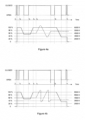
- this exemplifying scenario involves usage of a first light source 240a capable of providing white light at color temperature 3200 K and a second light source 240b capable of providing with light at color temperature of approximately 7000 K.
- a single input control signal having duration t in exceeding the second predetermined threshold Th L2 is assumed to result in the adjustment of ratio and the adjustment of combined light intensity in a sequential manner by first adjusting the combined light intensity of the first and the second light sources 240a, 240b without changing the ratio, followed by adjustment of the ratio of light intensities of the first and the second light sources 240a, 240b without changing the combined light intensity in dependence of the duration of the input control signal and in dependence of the current light intensities of the first and/or second light sources 240a, 240b.
- Figure 4a provides an example illustrating the relationship between the input control signal, the change in the combined light intensity and the color temperature.
- the color temperature reflects the ratio between the light intensities of the first and the second light sources 240a, 240b.
- the upper diagram of Figure 4a shows as the bold line the status of the switch controlled by the push-button 212 as a function of time and, consequently, indicates input control signals received by the controller 220.
- the lower diagram of Figure 4a illustrates as the bold solid line the (relative) combined light intensity as a function of time and as the bold dashed line the color temperature as a function of time.
- a first input control signal commencing at time t 1 in response to the push-button 212 being pushed is a short one, hence causing the controller 220 to control switching the one or more light elements 240 on after termination of the first input control signal at a maximum combined light intensity at color temperature of approximately 4500 K.
- a second input control signal commencing at time t 2 is a long one, causing the controller 220 to control decreasing the combined light intensity starting at t 2 + Th L2 until termination of the second input control signal, resulting in the combined light intensity being brought to approximately 55 % of the maximum combined light intensity without affecting the color temperature.
- a third input control signal commencing at time t 3 is a long one, and it first causes the controller 220 to control increasing the combined light intensity starting at t 3 + Th L2 until the maximum combined light intensity has been reached at time t 4 .
- the ratio is adjusted first to provide higher color temperatures, followed by adjustment of the ratio to provide lower color temperatures after reaching the maximum color temperature approximately at 7000 K, further followed by adjustment of the ratio to provide higher color temperatures after reaching the minimum color temperature at approximately 3200 K.
- the maximum color temperature is reached when the first light source 240a provides a zero light intensity with the second light source 240b providing the (selected) maximum light intensity, while the minimum color temperature is reached when the first light source 240a provides its (selected) maximum light intensity with the second light source 240b providing a zero light intensity.
- the adjustment of the ratio is terminated in response to termination of the third input control signal, resulting in the color temperature of approximately 5200 K.
- a fourth input control signal commencing at time t 6 is a long one, causing the controller 220 to control decreasing the combined light intensity starting at t 6 + Th L2 until termination of the fourth input control signal, resulting in the combined light intensity being brought to approximately 35 % of the maximum overall light intensity without affecting the ratio between the light intensities and hence the color temperature.
- a fifth input control signal commencing at time t 7 is a short one, causing the controller 220 to control switching the one or more light elements 240 off after termination of the fifth input control signal.
- Figure 4b provides an example illustrating the relationship between the input control signal, the change in the combined light intensity and the ratio between the light intensities (reflected in the color temperature) in accordance with a second exemplifying scenario assuming the adjustment of the ratio to the other extreme in response to reaching a (selected) maximum or a (selected) minimum light intensity of a light source 240a, 240b.
- the upper diagram shows as the bold line the status of the switch controlled by the push-button 212 as a function of time and the lower diagram illustrates as the bold solid line the (relative) combined light intensity as a function of time and as the bold dashed line the ratio of light intensities and hence the color temperature as a function of time.
- the durations and timing of the input control signals of the example of Figure 4b are identical to those of the example of Figure 4a .
- the responses to the first and second input control signals are the same as described hereinbefore in context of the example illustrated in Figure 4a .
- the adjustment of ratio and hence the adjustment of the color temperature is terminated in response to termination of the third input control signal, resulting in the color temperature of approximately 3700 K.
- the responses to the fourth and fifth control signals are identical to those described in context of the example of Figure 4a , while the ratio of light intensities of the first and the second light sources 240a, 240b and hence the resulting color temperature after the third input control signal is different from that of the first exemplifying scenario of Figure 4 .
- the controller 220 may, optionally, further comprise a driver portion 226, as schematically illustrated in Figure 5 .
- the driver portion 226 is configured to drive operation of the two or more light sources 240, e.g. the first light source 240a and the second light source 240b in accordance with control provided by the controller 220.
- the control may be carried out by the controller 220 issuing control signal(s) or commands, as described hereinbefore.
- the driver portion 226 may be configured to switch the first light source 240a and/or the second light source 240b on or off and to change the light intensity provided by the first light source 240a and/or by the second light source 240b in accordance with the control provided by the controller 220.
- the driver portion 226 may be further configured to drive or control further functions of the two or more light elements 240.
- the driver portion 226 may be configured to switch the first and the second light sources 240 on or off and/or to change light intensity of the first or the second light source 240a, 240b by changing the operating parameters of the respective light sources 240. This may involve initiating or discontinuing provision of the operating power to the two or more light sources 240 in order to switch the respective light sources on or off. Moreover, this may involve changing a signal providing operating power to the first or the second light source 240a, 240b, e.g. by changing the characteristics of the voltage and/or electric current provided to the respective light source 240a, 240b in order to result in a desired change in its light intensity. Such change of characteristics may comprise e.g.
- the driver portion 226 may be configured to provide to the control portion 224 an indication of the (selected) maximum light intensity of a light source 240a, 240b or the (selected) minimum light intensity of a light source 240a, 240b having been reached to facilitate controlling the change of characteristics. Moreover, the driver portion 226 may be further configured to provide to the control portion 224 indication(s) of the current light intensities of the first and the second light sources 240a, 240b to facilitate monitoring of the prevailing combined light intensity and/or the ratio of the light intensities. Conversely, the control portion 224 may be configured to receive such indication(s) from the driver portion 226.
- the function(s) and/or the operation(s) of the driver portion 226 may be provided as a driver 230 forming a logical and functional entity separate from the controller 220, as schematically illustrated in Figure 6 .
- the driver 230, performing the operations and/or functions described hereinbefore for the driver portion 226 may be provided in an apparatus separate from the apparatus acting as or hosting the controller 220.
- the driver 230 may be provided with a single input for receiving control information, e.g. output control signals or commands, from the controller 220 addressed for the first light source 240a or the second light source 240b.
- the control signals or commands may comprise information identifying the respective light source 240a, 240b to enable the driver 230 to address the output control signal or the command to the intended light source 240a, 240b of the two or more light sources 240.
- the driver 230 may be provided with a dedicated input for each light source 240a, 240b for receiving control, e.g. output control signals or commands, from the controller 220 addressed to the respective light source 240a, 240b.
- dedicated inputs it may not be necessary to include the information identifying the respective light element in the control signals or commands received at the driver 230.
- the controller 220 may control operation of the two or more light sources 240 via two or more drivers.
- the two or more drivers may comprise a first driver 230a for driving operation of the first light source 240a and a second driver 230b for driving operation of the second light source 240b, as schematically illustrated in Figure 7 .
- the first driver 230a and the second driver 230b may be hence considered to represent two or more drivers, each configured to control operation of the respective light source 240a, 240b connectable thereto independently of the other drivers (but in control of the controller 220).
- the driving portion 226 or the driver 230 if present, provides a driver function or a driver apparatus in accordance with the characteristics and requirements of the light source 240a, 240b it is configured to drive.
- the driver may comprise a LED driver and the light sources connectable thereto may comprise one or more LED light sources.
- the driver may comprise an electrical ballast and the light sources connectable thereto may comprise one or more fluorescent lamps.
- the driver may comprise a driver for a HID lamp while the light sources connectable thereto may comprise one or more HID lamps.
- the operations, procedures and/or functions assigned to the structural units of the controller 220 may be divided between these portions in a different manner.
- the controller 220 may comprise further portions or units that may be configured to perform some of the operations, procedures and/or functions assigned to the input portion 222, to the control portion 224 and/or to the possible driver portion 226 in the description hereinbefore.
- the operations, procedures and/or functions assigned to the input portion 222, to the control portion 224 and to the possible driver portion 226 may be assigned to a single portion or to a single processing unit within the controller 220.
- the controller 220 may be provided as a control apparatus for controlling operation of a first light source 240a of a first color and a second light source 240b of a second color, the control apparatus comprising means for receiving an input control signal having a user-controllable duration, means for switching, in response to a single input control signal having the overall duration t in not exceeding a first predetermined threshold Th L1 , the first light source 240a and the second light source 240b on or off, and means for changing the characteristics of light provided by the first and second light sources 240a, 240b, in response to the duration of the input control signal t in exceeding a second predetermined threshold Th L2 that is no smaller than the first predetermined threshold, the change in characteristics being dependent on duration of the input control signal and the change comprising adjustment of the ratio between the light intensities of the first light source and the second light source.
- Figure 8 schematically illustrates an exemplifying apparatus 800 that may be employed for embodying the present invention.
- the apparatus 800 comprises a processor 810 and a memory 820, the processor 810 being configured to read from and write to the memory 820.
- the apparatus 800 may further comprise a communication interface 830, such as a network card or a network adapter enabling wireless or wired communication with one or more another apparatuses.
- the apparatus 800 may further comprise a user interface 840 for providing data, commands and/or other input to the processor 810 and/or for receiving data or other output from the processor 810, the user interface 840 comprising for example one or more of a display, one or more keys, a keyboard, a mouse or a respective pointing device, a touchscreen, etc.
- the apparatus 800 may comprise further components not illustrated in the example of Figure 8 .
- processor 810 is presented in the example of Figure 8 as a single component, the processor 810 may be implemented as one or more separate components.
- memory 820 is illustrated as single component, the memory 820 may be implemented as one or more separate components, some or all of which may be integrated/removable and/or may provide permanent/semi-permanent/ dynamic/cached storage.
- the apparatus 800 may be embodied as a special-purpose or as a general purpose device with a sufficient processing capacity. Alternatively, the apparatus 800 may be embodied as an apparatus dedicated for operating as the controller 220 described hereinbefore.
- the memory 820 may store a computer program 850 comprising computer-executable instructions that control the operation of the apparatus 800 when loaded into the processor 810 and executed by the processor 810.
- the computer program 850 may include one or more sequences of one or more instructions.
- the computer program 850 may be provided as a computer program code.
- the processor 810 is able to load and execute the computer program 850 by reading the one or more sequences of one or more instructions included therein from the memory 820.
- the one or more sequences of one or more instructions may be configured to, when executed by one or more processors, cause an apparatus, for example the apparatus 800, to implement the operations, procedures and/or functions described hereinbefore in context of the controller 220.
- the apparatus 800 may comprise at least one processor 810 and at least one memory 820 including computer program code for one or more programs, the at least one memory 820 and the computer program code configured to, with the at least one processor 810, cause the apparatus 800 to perform the operations, procedures and/or functions described hereinbefore in context of the controller 220.
- the computer program 850 may be provided independently of the apparatus, and the computer program 850 may be provided at the apparatus 800 via any suitable delivery mechanism.
- the delivery mechanism may comprise at least one computer readable non-transitory medium having program code stored thereon, the program code which when executed by an apparatus cause the apparatus at least implement processing to carry out the operations, procedures and/or functions described hereinbefore in context of the controller 220.
- the delivery mechanism may be for example a computer readable storage medium, a computer program product, a memory device a record medium such as a CD-ROM, a DVD, a corresponding optical media, an article of manufacture that tangibly embodies the computer program 850, etc.
- the delivery mechanism may be a signal configured to reliably transfer the computer program 850.
- references to a processor should not be understood to encompass only programmable processors, but also dedicated circuits such as field-programmable gate arrays (FPGA), application specific circuits (ASIC), signal processors, etc.
- FPGA field-programmable gate arrays
- ASIC application specific circuits
- signal processors etc.
Landscapes
- Circuit Arrangement For Electric Light Sources In General (AREA)
Claims (10)
- Vorrichtung zum Steuern/Regeln vom Betrieb einer ersten Lichtquelle (240a) einer ersten Farbe und einer zweiten Lichtquelle (240b) einer zweiten Farbe, wobei die Vorrichtungeinen Eingabeabschnitt (222) aufweist, der konfiguriert ist, um ein Eingabesteuersignal mit einer vom Benutzer steuerbaren Dauer zu empfangen,dadurch gekennzeichnet, dass die Vorrichtung einen Steuerabschnitt (224) aufweist, welcher konfiguriert ist zum:Ein- oder Ausschalten der ersten (240a) und der zweiten (240b) Lichtquelle, in Antwort auf ein einzelnes Eingabesteuersignal, dessen Gesamtdauer einen ersten vorbestimmten Schwellenwert nicht überschreitet, undÄndern von Charakteristiken des Lichts, das von der ersten (240a) und zweiten (240b) Lichtquelle geliefert wird, in Antwort darauf, dass die Dauer des Eingabesteuersignals einen zweiten vorbestimmten Schwellenwert überschreitet, der nicht kleiner als der erste vorbestimmte Schwellenwert ist, wobei die Änderung in den Charakteristiken von der Dauer des Eingabesteuersignals abhängig ist, und die Änderung eine Einstellung des Verhältnisses zwischen den Lichtintensitäten der ersten Lichtquelle (240a) und der zweiten Lichtquelle (240b) aufweist, und wobei die Änderung ferner aufweist: Einstellung der kombinierten Lichtintensität der ersten Lichtquelle (240a) und der zweiten Lichtquelle (240b) derart, dass das Verhältnis zwischen der Lichtintensität der ersten Lichtquelle (240a) und der zweiten Lichtquelle (240b) im Wesentlichen konstant bleibt;wobei die Einstellung der kombinierten Lichtintensität zunächst in Antwort auf das Eingangssteuersignal erfolgt, wenn die Dauer des Eingabesteuersignals den zweiten vorbestimmten Schwellenwert überschreitet, so dass der Steuerabschnitt konfiguriert ist, die Einstellung der kombinierten Lichtintensität fortzusetzen, bis das Eingabesteuersignal endet oder bis eine maximale oder eine minimale kombinierte Lichtintensität der ersten (240a) und der zweiten (240b) Lichtquelle erreicht ist, und danach die Einstellung des Verhältnisses zwischen den Lichtintensitäten auszuführen.
- Vorrichtung nach Anspruch 1, wobei die Änderung aufweist: Einstellen des Verhältnisses zwischen den Lichtintensitäten der ersten Lichtquelle (240a) und der zweiten Lichtquelle (240b) gemäß einer ersten vorbestimmten Regel in Antwort darauf, dass das Eingabesteuersignal nach einer vorbestimmten Zeitdauer fortdauert, nachdem das Erreichen der maximalen kombinierten Lichtintensität der ersten (240a) und der zweiten (240b) Lichtquelle abgelaufen ist.
- Vorrichtung nach Anspruch 2, wobei die erste vorbestimmte Regel aufweist: Einstellen des Verhältnisses durch Erhöhen der Lichtintensität der ersten Lichtquelle (240a) in Bezug auf die Lichtintensität der zweiten Lichtquelle (240b), bis das Eingabesteuersignal endet oder bis die maximale Lichtintensität der ersten Lichtquelle (240a) und/oder die minimale Lichtintensität der zweiten Lichtquelle (240b) erreicht ist.
- Vorrichtung nach Anspruch 3, wobei die Einstellung des Verhältnisses, nach Erreichen der maximalen Lichtintensität der ersten Lichtquelle (240a) und/oder der minimalen Lichtintensität der zweiten Lichtquelle (240b), ferner eines vom Folgenden aufweist:Verringern der Lichtintensität der ersten Lichtquelle (240a) in Bezug auf die Lichtintensität der zweiten Lichtquelle (240b), bis das Eingabesteuersignal endet oder bis eine minimale Lichtintensität der ersten Lichtquelle (240a) und/oder eine maximale Lichtintensität der zweiten Lichtquelle (240b) erreicht ist, undSetzen der Lichtintensität der ersten Lichtquelle (240a) auf ihre minimale Lichtintensität und der Lichtintensität der zweiten Lichtquelle (240b) auf ihre maximale Lichtintensität, und Erhöhen der Lichtintensität der ersten Lichtquelle (240a) in Bezug auf die Lichtintensität der zweiten Lichtquelle (240b), bis das Eingabesteuersignal endet oder bis die maximale Lichtintensität der ersten Lichtquelle (240a) und/oder die minimale Lichtintensität der zweiten Lichtquelle (240b) erreicht ist.
- Vorrichtung nach Anspruch 4, wobei die Einstellung des Verhältnisses, nach Erreichen der maximalen Lichtintensität der ersten Lichtquelle (240a) und/oder der minimalen Lichtintensität der zweiten Lichtquelle (240b), ferner aufweist: Abwarten einer zweiten vorbestimmten Zeitdauer vor einer weiteren Einstellung des Verhältnisses zwischen den Lichtintensitäten der ersten (240a) und der zweiten (240b) Lichtquelle.
- Vorrichtung nach einem vorhergehenden Anspruch, wobei die Einstellung des Verhältnisses zwischen den Lichtintensitäten der ersten Lichtquelle (240a) und der zweiten Lichtquelle (240b) derart erfolgt, dass die kombinierte Lichtintensität der ersten Lichtquelle (240a) und der zweiten Lichtquelle (240b) im Wesentlichen konstant bleibt.
- Vorrichtung nach einem vorhergehenden Anspruch, wobei die Änderung in der Lichtintensität der ersten Lichtquelle (240a) und/oder der zweiten Lichtquelle (240b) als eine oder mehrere Änderungen eines vorbestimmten Betrags bereitgestellt wird, wobei jede Änderung die Lichtintensität der entsprechenden Lichtquelle um den vorbestimmten Betrag erhöht oder verringert.
- Vorrichtung nach einem vorhergehenden Anspruch, wobei die Vorrichtung konfiguriert ist, um ein oder mehrere Steuersignale auszugeben, um eine gewünschte Änderung in der Lichtintensität der ersten Lichtquelle (240a) und/oder der zweiten Lichtquelle (240b) zu bewirken.
- Vorrichtung nach Anspruch 1, welche aufweist:
zumindest einen Prozessor (810) und zumindest einen Speicher (820), der einen Computerprogramm-Code für ein oder mehrere Programme enthält, wobei der zumindest eine Speicher (820) und der Computerprogramm-Code konfiguriert sind, um mit dem zumindest einen Prozessor (810) zu bewirken, dass die Vorrichtung zumindest den Eingabeabschnitt (222) und den Steuerabschnitt (224) implementiert. - Computerprogramm zum Steuern/Regeln vom Betrieb einer ersten Lichtquelle (240a) einer ersten Farbe und einer zweiten Lichtquelle (240b) einer zweiten Farbe, wobei das Computerprogramm eine oder mehrere Sequenzen von einer oder mehreren Instruktionen enthält, die, wenn sie von einem oder mehreren Prozessoren ausgeführt werden, bewirken, dass eine Vorrichtung zumindest das Folgende durchführt:Empfangen eines Eingabesteuersignals mit einer vom Benutzer steuerbaren Dauer,dadurch gekennzeichnet, dass das Computerprogramm, wenn es von dem einen oder mehreren Prozessoren ausgeführt wird, bewirkt, dass die Vorrichtung:die erste (240a) und die zweite (240b) Lichtquelle, in Antwort auf ein einzelnes Eingabesteuersignal, dessen Gesamtdauer einen ersten vorbestimmten Schwellenwert nicht überschreitet, ein- oder ausschaltet, undCharakteristiken des Lichts ändert, das von der ersten (240a) und zweiten (240b) Lichtquelle geliefert wird, in Antwort darauf, dass die Dauer des Eingabesteuersignals einen zweiten vorbestimmten Schwellenwert überschreitet, der nicht kleiner als der erste vorbestimmte Schwellenwert ist, wobei die Änderung in den Charakteristiken von der Dauer des Eingabesteuersignals abhängig ist, und die Änderung eine Einstellung des Verhältnisses zwischen den Lichtintensitäten der ersten Lichtquelle (240a) und der zweiten Lichtquelle (240b) aufweist, und die Änderung ferner aufweist: Einstellung der kombinierten Lichtintensität der ersten Lichtquelle (240a) und der zweiten Lichtquelle (240b) derart, dass das Verhältnis zwischen der Lichtintensität der ersten Lichtquelle (240a) und der zweiten Lichtquelle (240b) im Wesentlichen konstant bleibt,wobei die Einstellung der kombinierten Lichtintensität zuerst in Antwort auf das Eingabesteuersignal erfolgt und die Einstellung der kombinierten Lichtintensität fortgesetzt wird, bis das Eingabesteuersignal endet oder bis eine maximale oder eine minimale kombinierte Lichtintensität der ersten (240a) und der zweiten (240b) Lichtquelle erreicht ist, und die Einstellung des Verhältnisses zwischen den Lichtintensitäten danach ausgeführt wird.
Priority Applications (3)
| Application Number | Priority Date | Filing Date | Title |
|---|---|---|---|
| EP12190767.9A EP2728972B2 (de) | 2012-10-31 | 2012-10-31 | Steuerung des Betriebs von Lichtquellen |
| EA201391417A EA030680B1 (ru) | 2012-10-31 | 2013-10-29 | Устройство для управления работой источников света |
| CN201310530672.9A CN103796378B (zh) | 2012-10-31 | 2013-10-31 | 光源的控制操作 |
Applications Claiming Priority (1)
| Application Number | Priority Date | Filing Date | Title |
|---|---|---|---|
| EP12190767.9A EP2728972B2 (de) | 2012-10-31 | 2012-10-31 | Steuerung des Betriebs von Lichtquellen |
Publications (3)
| Publication Number | Publication Date |
|---|---|
| EP2728972A1 EP2728972A1 (de) | 2014-05-07 |
| EP2728972B1 EP2728972B1 (de) | 2015-08-26 |
| EP2728972B2 true EP2728972B2 (de) | 2024-10-30 |
Family
ID=47323888
Family Applications (1)
| Application Number | Title | Priority Date | Filing Date |
|---|---|---|---|
| EP12190767.9A Active EP2728972B2 (de) | 2012-10-31 | 2012-10-31 | Steuerung des Betriebs von Lichtquellen |
Country Status (3)
| Country | Link |
|---|---|
| EP (1) | EP2728972B2 (de) |
| CN (1) | CN103796378B (de) |
| EA (1) | EA030680B1 (de) |
Families Citing this family (26)
| Publication number | Priority date | Publication date | Assignee | Title |
|---|---|---|---|---|
| EP2728972B2 (de) | 2012-10-31 | 2024-10-30 | Helvar Oy Ab | Steuerung des Betriebs von Lichtquellen |
| US10129943B2 (en) * | 2014-10-28 | 2018-11-13 | Taolight Company Limited | Dimmable LED module and method of using same |
| DE102015118725B3 (de) * | 2015-11-02 | 2017-02-09 | Vossloh-Schwabe Deutschland Gmbh | Betriebsgerät für Gruppenschaltung und Verfahren zum Steuern einer solchen Gruppenschaltung |
| FI20155900A7 (fi) | 2015-12-01 | 2017-06-02 | Helvar Oy Ab | Valonlähteiden toiminnan synkronointi |
| LU100351B1 (en) * | 2017-07-28 | 2019-02-12 | Titian Touch Sarl | Sensor system and apparatus |
| CN109729614A (zh) * | 2017-10-27 | 2019-05-07 | 凹凸电子(武汉)有限公司 | 控制器、光源驱动电路及控制光源模块的方法 |
| US10674579B2 (en) | 2018-01-26 | 2020-06-02 | Abl Ip Holding Llc | Lighting fixture with selectable color temperature |
| US10856384B2 (en) | 2018-05-29 | 2020-12-01 | Abl Ip Holding Llc | Lighting system with configurable color temperatures |
| US10448471B1 (en) | 2018-06-29 | 2019-10-15 | Abl Ip Holding Llc | Lighting system with configurable dimming |
| US10952292B2 (en) | 2018-08-09 | 2021-03-16 | Abl Ip Holding Llc | Programmable driver for variable light intensity |
| HUE059181T2 (hu) * | 2018-09-03 | 2022-10-28 | Signify Holding Bv | Fényforrás aktiválása a megelõzõ bekapcsolt idõtartam függvényében |
| US20220090760A1 (en) * | 2019-01-18 | 2022-03-24 | Research And Development Center “Biolumen” Limited Liability Company | Led white light source with a biologically adequate emission spectrum |
| US10874006B1 (en) | 2019-03-08 | 2020-12-22 | Abl Ip Holding Llc | Lighting fixture controller for controlling color temperature and intensity |
| CN113748748B (zh) | 2019-04-25 | 2024-05-17 | 昕诺飞控股有限公司 | 用于照明系统的控制器 |
| US11259377B2 (en) | 2019-05-17 | 2022-02-22 | Abl Ip Holding Llc | Color temperature and intensity configurable lighting fixture using de-saturated color LEDs |
| EP3749060B1 (de) * | 2019-06-05 | 2024-05-01 | Helvar Oy Ab | Selbstkonfigurierende beleuchtungssteuerung |
| JP7421277B2 (ja) * | 2019-06-28 | 2024-01-24 | コイズミ照明株式会社 | 照明器具 |
| US11359794B2 (en) | 2019-10-17 | 2022-06-14 | Abl Ip Holding Llc | Selectable lighting intensity and color temperature using luminaire lens |
| US12082317B2 (en) | 2019-10-30 | 2024-09-03 | Abl Ip Holding Llc | Light fixture controller having selectable light intensity and color temperature |
| US12273969B2 (en) | 2019-11-08 | 2025-04-08 | Abl Ip Holding Llc | Light fixture with externally selectable intensity or color temperature |
| US12133302B2 (en) | 2019-11-19 | 2024-10-29 | Spa Electrics Pty Ltd | System and method for controlling electrical devices |
| WO2022037759A1 (de) * | 2020-08-18 | 2022-02-24 | Vega Grieshaber Kg | Feldgerät, messanordnung sowie zum betreiben eins solchen feldgeräts |
| US11641708B2 (en) | 2020-08-28 | 2023-05-02 | Abl Ip Holding Llc | Light fixture controllable via dual networks |
| US11083061B1 (en) | 2020-10-16 | 2021-08-03 | Abl Ip Holding Llc | Systems to control light output characteristics of a lighting device |
| CA3181238A1 (en) * | 2020-12-09 | 2022-06-16 | Mark EIDING | System for controlling load control parameters over fade times |
| WO2023131503A1 (en) * | 2022-01-10 | 2023-07-13 | Signify Holding B.V. | Lighting system adapted to provide different light scenes |
Family Cites Families (11)
| Publication number | Priority date | Publication date | Assignee | Title |
|---|---|---|---|---|
| DE19757295B4 (de) | 1997-03-04 | 2005-08-04 | Tridonicatco Gmbh & Co. Kg | Elektronisches Vorschaltgerät |
| DE29724657U1 (de) * | 1997-03-04 | 2002-09-05 | TridonicAtco GmbH & Co. KG, Dornbirn | Elektronisches Vorschaltgerät |
| US6777892B2 (en) | 2000-01-14 | 2004-08-17 | Patent-Treuhand-Gesellschaft Fur Elektrische Gluhlampen Mbh | Device for controlling operating means for at least one electric illuminating means and a method for controlling operating means for at least one electric illuminating means |
| JP2002164182A (ja) | 2000-11-24 | 2002-06-07 | Moriyama Sangyo Kk | カラー照明装置 |
| DE102004045515A1 (de) * | 2004-09-20 | 2006-03-30 | Patent-Treuhand-Gesellschaft für elektrische Glühlampen mbH | Beleuchtungssystem mit mindestens zwei Lichtquellen und Verfahren zum Betreiben eines derartigen Beleuchtungssystems |
| JP2010176985A (ja) | 2009-01-28 | 2010-08-12 | Panasonic Electric Works Co Ltd | 照明装置 |
| TW201110810A (en) * | 2009-09-08 | 2011-03-16 | Wan-Yu Hsieh | Light emitting diode illuminator and illumination control interface |
| EP2491765A1 (de) | 2009-10-23 | 2012-08-29 | Tridonic GmbH & Co KG | Betrieb einer led-leuchte mit variablem spektrum |
| US8441202B2 (en) * | 2009-10-26 | 2013-05-14 | Light-Based Technologies Incorporated | Apparatus and method for LED light control |
| WO2011107280A2 (de) | 2010-03-03 | 2011-09-09 | Tridonic Ag | Steuerbares betriebsgerät für leuchtdioden |
| EP2728972B2 (de) | 2012-10-31 | 2024-10-30 | Helvar Oy Ab | Steuerung des Betriebs von Lichtquellen |
-
2012
- 2012-10-31 EP EP12190767.9A patent/EP2728972B2/de active Active
-
2013
- 2013-10-29 EA EA201391417A patent/EA030680B1/ru not_active IP Right Cessation
- 2013-10-31 CN CN201310530672.9A patent/CN103796378B/zh active Active
Also Published As
| Publication number | Publication date |
|---|---|
| EP2728972B1 (de) | 2015-08-26 |
| EA201391417A1 (ru) | 2014-07-30 |
| CN103796378A (zh) | 2014-05-14 |
| CN103796378B (zh) | 2019-02-12 |
| EP2728972A1 (de) | 2014-05-07 |
| EA030680B1 (ru) | 2018-09-28 |
Similar Documents
| Publication | Publication Date | Title |
|---|---|---|
| EP2728972B2 (de) | Steuerung des Betriebs von Lichtquellen | |
| US9474127B2 (en) | Lighting system and luminaire | |
| US8669721B2 (en) | Solid state light source based lighting device and lighting system | |
| JP6143759B2 (ja) | 固体照明装置の調光を制御するシステム及び方法 | |
| US9900963B1 (en) | Lighting controller | |
| KR20100116615A (ko) | 광원 | |
| CN107006090B (zh) | 驱动照明元件 | |
| TW201008381A (en) | Control unit for an LED assembly and lighting system | |
| TW201143501A (en) | LED drive circuit, dimming device, LED illumination fixture, LED illumination device, and LED illumination system | |
| CN106941740A (zh) | 一种电源开关控制led无极调光调色温的方法与装置 | |
| TW201119504A (en) | Method and apparatus providing universal voltage input for solid state light fixtures | |
| CN101836503A (zh) | 调光器抖动校正 | |
| US9516717B2 (en) | Dimmable LED illuminating system, driver of the illuminating system, and method of driving the illuminating system | |
| US20150042236A1 (en) | Method and apparatus for controlling brightness of light emitting diodes | |
| JP2016507138A (ja) | 調光可能な発光ダイオード照明システムおよびその駆動装置と駆動方法 | |
| CN111345117B (zh) | 固态照明电路和控制方法 | |
| US8829818B2 (en) | Control of operational parameters of operational devices for LEDs | |
| US9101002B2 (en) | Method of controlling multiple lamps | |
| TW201042193A (en) | Lighting device with a time-varying illumination function | |
| US20160174342A1 (en) | Method for controlling lighting element and associated system | |
| US9674914B2 (en) | Driver unit and driving method for driving a load | |
| JP2006278051A (ja) | 照明制御装置および照明システム | |
| TWM393128U (en) | Lighting device | |
| HK1164623B (en) | Method and apparatus for controlling brightness of light emitting diodes |
Legal Events
| Date | Code | Title | Description |
|---|---|---|---|
| PUAI | Public reference made under article 153(3) epc to a published international application that has entered the european phase |
Free format text: ORIGINAL CODE: 0009012 |
|
| 17P | Request for examination filed |
Effective date: 20121031 |
|
| AK | Designated contracting states |
Kind code of ref document: A1 Designated state(s): AL AT BE BG CH CY CZ DE DK EE ES FI FR GB GR HR HU IE IS IT LI LT LU LV MC MK MT NL NO PL PT RO RS SE SI SK SM TR |
|
| AX | Request for extension of the european patent |
Extension state: BA ME |
|
| 17P | Request for examination filed |
Effective date: 20141028 |
|
| RBV | Designated contracting states (corrected) |
Designated state(s): AL AT BE BG CH CY CZ DE DK EE ES FI FR GB GR HR HU IE IS IT LI LT LU LV MC MK MT NL NO PL PT RO RS SE SI SK SM TR |
|
| GRAP | Despatch of communication of intention to grant a patent |
Free format text: ORIGINAL CODE: EPIDOSNIGR1 |
|
| INTG | Intention to grant announced |
Effective date: 20150409 |
|
| GRAS | Grant fee paid |
Free format text: ORIGINAL CODE: EPIDOSNIGR3 |
|
| GRAA | (expected) grant |
Free format text: ORIGINAL CODE: 0009210 |
|
| AK | Designated contracting states |
Kind code of ref document: B1 Designated state(s): AL AT BE BG CH CY CZ DE DK EE ES FI FR GB GR HR HU IE IS IT LI LT LU LV MC MK MT NL NO PL PT RO RS SE SI SK SM TR |
|
| REG | Reference to a national code |
Ref country code: GB Ref legal event code: FG4D |
|
| REG | Reference to a national code |
Ref country code: CH Ref legal event code: EP |
|
| REG | Reference to a national code |
Ref country code: AT Ref legal event code: REF Ref document number: 745934 Country of ref document: AT Kind code of ref document: T Effective date: 20150915 |
|
| REG | Reference to a national code |
Ref country code: IE Ref legal event code: FG4D |
|
| REG | Reference to a national code |
Ref country code: DE Ref legal event code: R096 Ref document number: 602012009955 Country of ref document: DE |
|
| REG | Reference to a national code |
Ref country code: FR Ref legal event code: PLFP Year of fee payment: 4 |
|
| REG | Reference to a national code |
Ref country code: AT Ref legal event code: MK05 Ref document number: 745934 Country of ref document: AT Kind code of ref document: T Effective date: 20150826 |
|
| REG | Reference to a national code |
Ref country code: LT Ref legal event code: MG4D |
|
| PG25 | Lapsed in a contracting state [announced via postgrant information from national office to epo] |
Ref country code: NO Free format text: LAPSE BECAUSE OF FAILURE TO SUBMIT A TRANSLATION OF THE DESCRIPTION OR TO PAY THE FEE WITHIN THE PRESCRIBED TIME-LIMIT Effective date: 20151126 Ref country code: FI Free format text: LAPSE BECAUSE OF FAILURE TO SUBMIT A TRANSLATION OF THE DESCRIPTION OR TO PAY THE FEE WITHIN THE PRESCRIBED TIME-LIMIT Effective date: 20150826 Ref country code: LT Free format text: LAPSE BECAUSE OF FAILURE TO SUBMIT A TRANSLATION OF THE DESCRIPTION OR TO PAY THE FEE WITHIN THE PRESCRIBED TIME-LIMIT Effective date: 20150826 Ref country code: LV Free format text: LAPSE BECAUSE OF FAILURE TO SUBMIT A TRANSLATION OF THE DESCRIPTION OR TO PAY THE FEE WITHIN THE PRESCRIBED TIME-LIMIT Effective date: 20150826 Ref country code: GR Free format text: LAPSE BECAUSE OF FAILURE TO SUBMIT A TRANSLATION OF THE DESCRIPTION OR TO PAY THE FEE WITHIN THE PRESCRIBED TIME-LIMIT Effective date: 20151127 |
|
| REG | Reference to a national code |
Ref country code: NL Ref legal event code: MP Effective date: 20150826 |
|
| PG25 | Lapsed in a contracting state [announced via postgrant information from national office to epo] |
Ref country code: IS Free format text: LAPSE BECAUSE OF FAILURE TO SUBMIT A TRANSLATION OF THE DESCRIPTION OR TO PAY THE FEE WITHIN THE PRESCRIBED TIME-LIMIT Effective date: 20151226 Ref country code: SE Free format text: LAPSE BECAUSE OF FAILURE TO SUBMIT A TRANSLATION OF THE DESCRIPTION OR TO PAY THE FEE WITHIN THE PRESCRIBED TIME-LIMIT Effective date: 20150826 Ref country code: PT Free format text: LAPSE BECAUSE OF FAILURE TO SUBMIT A TRANSLATION OF THE DESCRIPTION OR TO PAY THE FEE WITHIN THE PRESCRIBED TIME-LIMIT Effective date: 20151228 Ref country code: ES Free format text: LAPSE BECAUSE OF FAILURE TO SUBMIT A TRANSLATION OF THE DESCRIPTION OR TO PAY THE FEE WITHIN THE PRESCRIBED TIME-LIMIT Effective date: 20150826 Ref country code: RS Free format text: LAPSE BECAUSE OF FAILURE TO SUBMIT A TRANSLATION OF THE DESCRIPTION OR TO PAY THE FEE WITHIN THE PRESCRIBED TIME-LIMIT Effective date: 20150826 Ref country code: AT Free format text: LAPSE BECAUSE OF FAILURE TO SUBMIT A TRANSLATION OF THE DESCRIPTION OR TO PAY THE FEE WITHIN THE PRESCRIBED TIME-LIMIT Effective date: 20150826 Ref country code: PL Free format text: LAPSE BECAUSE OF FAILURE TO SUBMIT A TRANSLATION OF THE DESCRIPTION OR TO PAY THE FEE WITHIN THE PRESCRIBED TIME-LIMIT Effective date: 20150826 Ref country code: HR Free format text: LAPSE BECAUSE OF FAILURE TO SUBMIT A TRANSLATION OF THE DESCRIPTION OR TO PAY THE FEE WITHIN THE PRESCRIBED TIME-LIMIT Effective date: 20150826 |
|
| PG25 | Lapsed in a contracting state [announced via postgrant information from national office to epo] |
Ref country code: NL Free format text: LAPSE BECAUSE OF FAILURE TO SUBMIT A TRANSLATION OF THE DESCRIPTION OR TO PAY THE FEE WITHIN THE PRESCRIBED TIME-LIMIT Effective date: 20150826 |
|
| PG25 | Lapsed in a contracting state [announced via postgrant information from national office to epo] |
Ref country code: IT Free format text: LAPSE BECAUSE OF FAILURE TO SUBMIT A TRANSLATION OF THE DESCRIPTION OR TO PAY THE FEE WITHIN THE PRESCRIBED TIME-LIMIT Effective date: 20150826 Ref country code: CZ Free format text: LAPSE BECAUSE OF FAILURE TO SUBMIT A TRANSLATION OF THE DESCRIPTION OR TO PAY THE FEE WITHIN THE PRESCRIBED TIME-LIMIT Effective date: 20150826 Ref country code: DK Free format text: LAPSE BECAUSE OF FAILURE TO SUBMIT A TRANSLATION OF THE DESCRIPTION OR TO PAY THE FEE WITHIN THE PRESCRIBED TIME-LIMIT Effective date: 20150826 Ref country code: SK Free format text: LAPSE BECAUSE OF FAILURE TO SUBMIT A TRANSLATION OF THE DESCRIPTION OR TO PAY THE FEE WITHIN THE PRESCRIBED TIME-LIMIT Effective date: 20150826 Ref country code: EE Free format text: LAPSE BECAUSE OF FAILURE TO SUBMIT A TRANSLATION OF THE DESCRIPTION OR TO PAY THE FEE WITHIN THE PRESCRIBED TIME-LIMIT Effective date: 20150826 |
|
| REG | Reference to a national code |
Ref country code: DE Ref legal event code: R026 Ref document number: 602012009955 Country of ref document: DE |
|
| PG25 | Lapsed in a contracting state [announced via postgrant information from national office to epo] |
Ref country code: RO Free format text: LAPSE BECAUSE OF FAILURE TO SUBMIT A TRANSLATION OF THE DESCRIPTION OR TO PAY THE FEE WITHIN THE PRESCRIBED TIME-LIMIT Effective date: 20150826 Ref country code: LU Free format text: LAPSE BECAUSE OF FAILURE TO SUBMIT A TRANSLATION OF THE DESCRIPTION OR TO PAY THE FEE WITHIN THE PRESCRIBED TIME-LIMIT Effective date: 20151031 |
|
| REG | Reference to a national code |
Ref country code: CH Ref legal event code: PL |
|
| PLBI | Opposition filed |
Free format text: ORIGINAL CODE: 0009260 |
|
| PG25 | Lapsed in a contracting state [announced via postgrant information from national office to epo] |
Ref country code: MC Free format text: LAPSE BECAUSE OF FAILURE TO SUBMIT A TRANSLATION OF THE DESCRIPTION OR TO PAY THE FEE WITHIN THE PRESCRIBED TIME-LIMIT Effective date: 20150826 |
|
| PLAX | Notice of opposition and request to file observation + time limit sent |
Free format text: ORIGINAL CODE: EPIDOSNOBS2 |
|
| 26 | Opposition filed |
Opponent name: TRIDONIC GMBH & CO KG Effective date: 20160527 |
|
| REG | Reference to a national code |
Ref country code: IE Ref legal event code: MM4A |
|
| PG25 | Lapsed in a contracting state [announced via postgrant information from national office to epo] |
Ref country code: CH Free format text: LAPSE BECAUSE OF NON-PAYMENT OF DUE FEES Effective date: 20151031 Ref country code: LI Free format text: LAPSE BECAUSE OF NON-PAYMENT OF DUE FEES Effective date: 20151031 |
|
| PG25 | Lapsed in a contracting state [announced via postgrant information from national office to epo] |
Ref country code: SI Free format text: LAPSE BECAUSE OF FAILURE TO SUBMIT A TRANSLATION OF THE DESCRIPTION OR TO PAY THE FEE WITHIN THE PRESCRIBED TIME-LIMIT Effective date: 20150826 |
|
| REG | Reference to a national code |
Ref country code: FR Ref legal event code: PLFP Year of fee payment: 5 |
|
| PLBB | Reply of patent proprietor to notice(s) of opposition received |
Free format text: ORIGINAL CODE: EPIDOSNOBS3 |
|
| PG25 | Lapsed in a contracting state [announced via postgrant information from national office to epo] |
Ref country code: IE Free format text: LAPSE BECAUSE OF NON-PAYMENT OF DUE FEES Effective date: 20151031 |
|
| PG25 | Lapsed in a contracting state [announced via postgrant information from national office to epo] |
Ref country code: BE Free format text: LAPSE BECAUSE OF FAILURE TO SUBMIT A TRANSLATION OF THE DESCRIPTION OR TO PAY THE FEE WITHIN THE PRESCRIBED TIME-LIMIT Effective date: 20150826 |
|
| PG25 | Lapsed in a contracting state [announced via postgrant information from national office to epo] |
Ref country code: BG Free format text: LAPSE BECAUSE OF FAILURE TO SUBMIT A TRANSLATION OF THE DESCRIPTION OR TO PAY THE FEE WITHIN THE PRESCRIBED TIME-LIMIT Effective date: 20150826 Ref country code: HU Free format text: LAPSE BECAUSE OF FAILURE TO SUBMIT A TRANSLATION OF THE DESCRIPTION OR TO PAY THE FEE WITHIN THE PRESCRIBED TIME-LIMIT; INVALID AB INITIO Effective date: 20121031 Ref country code: SM Free format text: LAPSE BECAUSE OF FAILURE TO SUBMIT A TRANSLATION OF THE DESCRIPTION OR TO PAY THE FEE WITHIN THE PRESCRIBED TIME-LIMIT Effective date: 20150826 |
|
| PG25 | Lapsed in a contracting state [announced via postgrant information from national office to epo] |
Ref country code: CY Free format text: LAPSE BECAUSE OF FAILURE TO SUBMIT A TRANSLATION OF THE DESCRIPTION OR TO PAY THE FEE WITHIN THE PRESCRIBED TIME-LIMIT Effective date: 20150826 |
|
| PG25 | Lapsed in a contracting state [announced via postgrant information from national office to epo] |
Ref country code: MT Free format text: LAPSE BECAUSE OF FAILURE TO SUBMIT A TRANSLATION OF THE DESCRIPTION OR TO PAY THE FEE WITHIN THE PRESCRIBED TIME-LIMIT Effective date: 20150826 |
|
| REG | Reference to a national code |
Ref country code: FR Ref legal event code: PLFP Year of fee payment: 6 |
|
| APBM | Appeal reference recorded |
Free format text: ORIGINAL CODE: EPIDOSNREFNO |
|
| APBP | Date of receipt of notice of appeal recorded |
Free format text: ORIGINAL CODE: EPIDOSNNOA2O |
|
| APAH | Appeal reference modified |
Free format text: ORIGINAL CODE: EPIDOSCREFNO |
|
| APBQ | Date of receipt of statement of grounds of appeal recorded |
Free format text: ORIGINAL CODE: EPIDOSNNOA3O |
|
| PG25 | Lapsed in a contracting state [announced via postgrant information from national office to epo] |
Ref country code: MK Free format text: LAPSE BECAUSE OF FAILURE TO SUBMIT A TRANSLATION OF THE DESCRIPTION OR TO PAY THE FEE WITHIN THE PRESCRIBED TIME-LIMIT Effective date: 20150826 |
|
| RAP2 | Party data changed (patent owner data changed or rights of a patent transferred) |
Owner name: HELVAR OY AB |
|
| REG | Reference to a national code |
Ref country code: FR Ref legal event code: PLFP Year of fee payment: 7 |
|
| PG25 | Lapsed in a contracting state [announced via postgrant information from national office to epo] |
Ref country code: TR Free format text: LAPSE BECAUSE OF FAILURE TO SUBMIT A TRANSLATION OF THE DESCRIPTION OR TO PAY THE FEE WITHIN THE PRESCRIBED TIME-LIMIT Effective date: 20150826 Ref country code: AL Free format text: LAPSE BECAUSE OF FAILURE TO SUBMIT A TRANSLATION OF THE DESCRIPTION OR TO PAY THE FEE WITHIN THE PRESCRIBED TIME-LIMIT Effective date: 20150826 |
|
| APAH | Appeal reference modified |
Free format text: ORIGINAL CODE: EPIDOSCREFNO |
|
| APBU | Appeal procedure closed |
Free format text: ORIGINAL CODE: EPIDOSNNOA9O |
|
| PLAY | Examination report in opposition despatched + time limit |
Free format text: ORIGINAL CODE: EPIDOSNORE2 |
|
| PLBC | Reply to examination report in opposition received |
Free format text: ORIGINAL CODE: EPIDOSNORE3 |
|
| PLAY | Examination report in opposition despatched + time limit |
Free format text: ORIGINAL CODE: EPIDOSNORE2 |
|
| PLBC | Reply to examination report in opposition received |
Free format text: ORIGINAL CODE: EPIDOSNORE3 |
|
| PUAH | Patent maintained in amended form |
Free format text: ORIGINAL CODE: 0009272 |
|
| STAA | Information on the status of an ep patent application or granted ep patent |
Free format text: STATUS: PATENT MAINTAINED AS AMENDED |
|
| 27A | Patent maintained in amended form |
Effective date: 20241030 |
|
| AK | Designated contracting states |
Kind code of ref document: B2 Designated state(s): AL AT BE BG CH CY CZ DE DK EE ES FI FR GB GR HR HU IE IS IT LI LT LU LV MC MK MT NL NO PL PT RO RS SE SI SK SM TR |
|
| REG | Reference to a national code |
Ref country code: DE Ref legal event code: R102 Ref document number: 602012009955 Country of ref document: DE |
|
| REG | Reference to a national code |
Ref country code: GB Ref legal event code: 732E Free format text: REGISTERED BETWEEN 20241205 AND 20241211 |
|
| PGFP | Annual fee paid to national office [announced via postgrant information from national office to epo] |
Ref country code: DE Payment date: 20241029 Year of fee payment: 13 |
|
| PGFP | Annual fee paid to national office [announced via postgrant information from national office to epo] |
Ref country code: GB Payment date: 20241028 Year of fee payment: 13 |
|
| PGFP | Annual fee paid to national office [announced via postgrant information from national office to epo] |
Ref country code: FR Payment date: 20241025 Year of fee payment: 13 |