EP2728851A1 - Camera module - Google Patents
Camera module Download PDFInfo
- Publication number
- EP2728851A1 EP2728851A1 EP13189607.8A EP13189607A EP2728851A1 EP 2728851 A1 EP2728851 A1 EP 2728851A1 EP 13189607 A EP13189607 A EP 13189607A EP 2728851 A1 EP2728851 A1 EP 2728851A1
- Authority
- EP
- European Patent Office
- Prior art keywords
- focal length
- coupling
- camera module
- adjusting unit
- lens
- Prior art date
- Legal status (The legal status is an assumption and is not a legal conclusion. Google has not performed a legal analysis and makes no representation as to the accuracy of the status listed.)
- Ceased
Links
Images




Classifications
-
- G—PHYSICS
- G02—OPTICS
- G02B—OPTICAL ELEMENTS, SYSTEMS OR APPARATUS
- G02B7/00—Mountings, adjusting means, or light-tight connections, for optical elements
- G02B7/02—Mountings, adjusting means, or light-tight connections, for optical elements for lenses
- G02B7/04—Mountings, adjusting means, or light-tight connections, for optical elements for lenses with mechanism for focusing or varying magnification
-
- G—PHYSICS
- G03—PHOTOGRAPHY; CINEMATOGRAPHY; ANALOGOUS TECHNIQUES USING WAVES OTHER THAN OPTICAL WAVES; ELECTROGRAPHY; HOLOGRAPHY
- G03B—APPARATUS OR ARRANGEMENTS FOR TAKING PHOTOGRAPHS OR FOR PROJECTING OR VIEWING THEM; APPARATUS OR ARRANGEMENTS EMPLOYING ANALOGOUS TECHNIQUES USING WAVES OTHER THAN OPTICAL WAVES; ACCESSORIES THEREFOR
- G03B30/00—Camera modules comprising integrated lens units and imaging units, specially adapted for being embedded in other devices, e.g. mobile phones or vehicles
-
- G—PHYSICS
- G02—OPTICS
- G02B—OPTICAL ELEMENTS, SYSTEMS OR APPARATUS
- G02B7/00—Mountings, adjusting means, or light-tight connections, for optical elements
- G02B7/02—Mountings, adjusting means, or light-tight connections, for optical elements for lenses
- G02B7/04—Mountings, adjusting means, or light-tight connections, for optical elements for lenses with mechanism for focusing or varying magnification
- G02B7/10—Mountings, adjusting means, or light-tight connections, for optical elements for lenses with mechanism for focusing or varying magnification by relative axial movement of several lenses, e.g. of varifocal objective lens
-
- G—PHYSICS
- G03—PHOTOGRAPHY; CINEMATOGRAPHY; ANALOGOUS TECHNIQUES USING WAVES OTHER THAN OPTICAL WAVES; ELECTROGRAPHY; HOLOGRAPHY
- G03B—APPARATUS OR ARRANGEMENTS FOR TAKING PHOTOGRAPHS OR FOR PROJECTING OR VIEWING THEM; APPARATUS OR ARRANGEMENTS EMPLOYING ANALOGOUS TECHNIQUES USING WAVES OTHER THAN OPTICAL WAVES; ACCESSORIES THEREFOR
- G03B17/00—Details of cameras or camera bodies; Accessories therefor
- G03B17/02—Bodies
-
- G—PHYSICS
- G03—PHOTOGRAPHY; CINEMATOGRAPHY; ANALOGOUS TECHNIQUES USING WAVES OTHER THAN OPTICAL WAVES; ELECTROGRAPHY; HOLOGRAPHY
- G03B—APPARATUS OR ARRANGEMENTS FOR TAKING PHOTOGRAPHS OR FOR PROJECTING OR VIEWING THEM; APPARATUS OR ARRANGEMENTS EMPLOYING ANALOGOUS TECHNIQUES USING WAVES OTHER THAN OPTICAL WAVES; ACCESSORIES THEREFOR
- G03B3/00—Focusing arrangements of general interest for cameras, projectors or printers
- G03B3/02—Focusing arrangements of general interest for cameras, projectors or printers moving lens along baseboard
-
- G—PHYSICS
- G03—PHOTOGRAPHY; CINEMATOGRAPHY; ANALOGOUS TECHNIQUES USING WAVES OTHER THAN OPTICAL WAVES; ELECTROGRAPHY; HOLOGRAPHY
- G03B—APPARATUS OR ARRANGEMENTS FOR TAKING PHOTOGRAPHS OR FOR PROJECTING OR VIEWING THEM; APPARATUS OR ARRANGEMENTS EMPLOYING ANALOGOUS TECHNIQUES USING WAVES OTHER THAN OPTICAL WAVES; ACCESSORIES THEREFOR
- G03B43/00—Testing correct operation of photographic apparatus or parts thereof
-
- H—ELECTRICITY
- H04—ELECTRIC COMMUNICATION TECHNIQUE
- H04N—PICTORIAL COMMUNICATION, e.g. TELEVISION
- H04N23/00—Cameras or camera modules comprising electronic image sensors; Control thereof
- H04N23/50—Constructional details
- H04N23/55—Optical parts specially adapted for electronic image sensors; Mounting thereof
-
- G—PHYSICS
- G03—PHOTOGRAPHY; CINEMATOGRAPHY; ANALOGOUS TECHNIQUES USING WAVES OTHER THAN OPTICAL WAVES; ELECTROGRAPHY; HOLOGRAPHY
- G03B—APPARATUS OR ARRANGEMENTS FOR TAKING PHOTOGRAPHS OR FOR PROJECTING OR VIEWING THEM; APPARATUS OR ARRANGEMENTS EMPLOYING ANALOGOUS TECHNIQUES USING WAVES OTHER THAN OPTICAL WAVES; ACCESSORIES THEREFOR
- G03B2217/00—Details of cameras or camera bodies; Accessories therefor
- G03B2217/002—Details of arrangement of components in or on camera body
Definitions
- the embodiment relates to a camera module.
- camera modules are mounted on portable appliances such as mobile communication terminals and MP3 players as well as electronic appliances such as vehicles, endoscopes, and CCTVs.
- the camera modules are increasingly developed toward small and thin camera modules while focusing on high resolution.
- the camera modules are realized with various added functions at low manufacturing cost.
- the camera module includes a lens barrel to receive a lens, a lens holder coupled with the lens barrel, and an image sensor provided in the lens holder.
- the lens transmits an image signal of a subject to the image sensor.
- the image sensor converts the image signal into an electrical signal.
- the accuracy of the image signal in the camera module is determined depending on a focal length defined as a distance between the lens and the image sensor.
- a focal length defined as a distance between the lens and the image sensor.
- the focal length must be accurately set.
- the accuracy of the focal length is determined after manufacturing the camera module. If it is determined that the focal length is not accurate, the focal length must be adjusted by disassembling the camera module. The above operations may be repeated several times until the focal length is determined as being accurate. Accordingly, long time to manufacture the camera module is required.
- the embodiment is to save time required to manufacture a camera module.
- the embodiment is to easily adjust the focal length in the camera module.
- the embodiment is to adjust the focal length without disassembling the camera module.
- a camera module including a lens barrel including a lens, a lens holder coupled with the lens barrel, and a sensor unit in the lens holder.
- the lens holder includes a body part including the sensor unit, and a focal length adjusting unit to adjust a focal length between the lens and the sensor unit.
- the focal length adjusting unit may be rotatably coupled with the body part.
- the body part may include a first step difference part formed in opposition to the focal length adjusting unit, and the focal length adjusting unit may include a second step difference part in opposition to the body part such that the second step difference part is engaged with the first step difference part.
- the first step difference part may include a plurality of first coupling surfaces partitioned according to step differences therebetween and arranged in a step structure
- the second step difference part may include a plurality of second coupling surfaces arranged in a shape corresponding to a shape of the first step difference part.
- At least one of the first coupling surfaces may be coupled with at least one of the second coupling surfaces as the focal length adjusting unit rotates corresponding to the body part such that the focal length is adjusted.
- the body part may include a first coupling surface formed in opposition to the focal length adjusting unit and inclined from an axis to connect a center of the lens with a center of the senor unit
- the focal length adjusting unit may include a second coupling surface formed in opposition to the body part and arranged in a shape corresponding to a shape of the first coupling surface such that the second coupling surface is engaged with the first coupling surface
- At least a portion of the first coupling surface may be coupled with at least a portion of the second coupling surface as the focal length adjusting unit rotates corresponding to the body part such that the focal length is adjusted.
- the focal length can be easily adjusted.
- the lens holder is divided into the body part and the focal length adjusting unit, and the focal length adjusting unit is configured movably from the body part. Accordingly, the distance between the lens assembly and the sensor unit can be adjusted without disassembling the camera module. Therefore, the time to manufacture the camera module can be saved.
- FIG. 1 is a perspective view showing a camera module according to one embodiment.
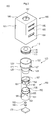
- FIG. 2 is an exploded perspective view showing the camera module of FIG. 1 .
- FIG. 3 shows views to explain the operation of a lens barrel of FIG. 1 .
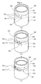
- FIG. 4 shows views to explain the operation of a lens holder of FIG. 1 .
- FIG. 5 shows views to explain the modification of a lens holder in the camera module according to one embodiment and the operation thereof.
- FIG. 6 is an exploded perspective view showing a camera module according to another embodiment.
- FIG. 1 is a perspective view showing a camera module according to one embodiment.
- FIG. 2 is an exploded perspective view showing the camera module of FIG. 1 .
- FIG. 3 shows views to explain the operation of a lens barrel of FIG. 1 .
- FIG. 4 shows views to explain the operation of a lens holder of FIG. 1 .
- a camera module 100 includes a lens assembly 110, a lens barrel 120, a filter unit 130, a sensor unit 140, a lens holder 150, a circuit board 170, and a housing 180.
- the lens assembly 110 includes at least one of lenses 111, 113, and 115. In this case, if the lens assembly 110 includes the lens 111, 113, and 115, the lenses 111, 113, and 115 are stacked in one direction. In this case, spacers (not shown) may be interposed among lenses 111, 113, and 115. The spacers spaces the lenses 111, 113, and 115 apart from each other so that the lenses 111, 113, and 115 are maintained at a predetermined interval. Further, the lens assembly 110 may have a circular outer shape. Alternatively, the lens assembly 110 may have a square outer shape.
- the lens barrel 120 receives the lens assembly 110 therein.
- the lens barrel 120 receives the lens assembly 110 in one direction.
- the lens barrel 120 exposes the lens assembly 110.
- the lens barrel 120 exposes the lens assembly 110 so that light is incident onto the lens assembly 110.
- the lens barrel 120 includes a fixing barrel 121, a first rotational barrel 123, a second rotational barrel 125, a first adjusting lever 127, and a second adjusting lever 129.
- the fixing barrel 121 receives the lens assembly 110 therein.
- the fixing barrel 121 has a structure in which a receiving hole 122 is formed, and the lens assembly 110 is received in the receiving hole 122.
- the receiving hole 122 may have the shape corresponding to the shape of the lens assembly 110.
- the receiving hole 122 may have a circular shape.
- the receiving hole 122 may have a polygonal shape.
- the fixing barrel 121 exposes the lens assembly 110.
- the first rotational barrel 123 is coupled with the fixing barrel 121.
- the first rotational barrel 123 is coupled with a front end portion of the fixing barrel 121.
- the first rotational barrel 123 is rotatably coupled with the fixing barrel 121.
- the first rotational barrel 123 surrounds the fixing barrel 121. Therefore, the first rotational barrel 123 may rotate corresponding to the fixing barrel 121 about an axis extending in one direction.
- first rotation graduations may be formed along an outer surface of the first rotational barrel to represent the rotational degree of the first rotational barrel 123.
- the second rotational barrel 125 is coupled with the fixing barrel 121.
- the second rotational barrel 125 is coupled with the fixing barrel 121 under the first rotational barrel 123.
- the second rotational barrel 125 is rotatably coupled with the fixing barrel 121.
- the second rotational barrel 125 surrounds the fixing barrel 121. Therefore, the second rotational barrel 125 may rotate corresponding to the fixing barrel 121 about an axis extending in one direction.
- second rotation graduations may be formed along an outer surface of the second rotational barrel 125 to represent the rotational degree of the second rotational barrel 125.
- the first adjusting lever 127 is mounted on the side portion of the first rotational barrel 123. In this case, the first adjusting lever 127 is fixed to the first rotational barrel 123. In addition, the first adjusting lever 127 protrudes from the first rotational barrel 123. In this case, the first adjusting lever 127 protrudes in another direction perpendicular to the one direction. Accordingly, the first adjusting lever 127 rotates integrally with the first rotational barrel 123 corresponding to the fixing barrel 121.
- the second adjusting lever 129 is mounted on the side portion of the second rotational barrel 125.
- the second adjusting lever 129 is fixed to the second rotational barrel 125.
- the second adjusting lever 129 protrudes from the second rotational barrel 125.
- the second adjusting lever 129 protrudes in another direction perpendicular to the one direction. Accordingly, the second adjusting lever 129 rotates integrally with the second rotational barrel 125 corresponding to the fixing barrel 121.
- the first adjusting lever 127 moves, rotational force is applied to the first rotational barrel 123. Accordingly, the first rotational barrel 123 may rotate corresponding to the fixing barrel 121. Therefore, the focus of the camera module 100 may be adjusted.
- the fixing barrel 121 may move the lens assembly 110 in the receiving hole 122 corresponding to the rotation of the first rotational barrel 123. Accordingly, the focus of the camera module can be adjusted. In this case, the focus of the camera module 100 can be adjusted to a long distance or a short distance.
- the lens assembly 110 may move in the fixing barrel 121. In other words, as the first rotational barrel 123 rotates, the lens assembly 110 may move in the receiving hole 122. In this case, the lens assembly 110 may move in one direction. For example, as shown in FIG. 3(a), when the first adjusting lever 127 is located at the left side, the lens assembly 110 may be located at an inner upper portion of the lens barrel 120. As shown in FIG. 3(b) , when the first adjusting lever 127 moves right, the lens assembly 110 may move down in the receiving hole 122.
- the second rotational barrel 125 may rotate corresponding to the fixing barrel 121.
- the fixing barrel 121 may adjust the exposed degree of the lens assembly 110 in the receiving hole 122 corresponding to the rotation of the second rotational barrel 125. Accordingly, the zoom range of the camera module 100 may be adjusted. In this case, the zoom range of the camera module 100 may be expanded or narrowed.
- the filter unit 130 is provided under the lens barrel 120.
- the filter unit 130 filters the light incident thereon from the lens assembly 110.
- the filter unit 130 may cut off infrared light.
- the filter unit 130 may cut off light having a long wavelength.
- the filter unit 130 may be formed by alternately depositing titanium oxide and silicon oxide on optical glass. In this case, the optical characteristic of the filter unit 130 to cut off the infrared light may be adjusted according to the thicknesses of titanium oxide and silicon oxide.
- the sensor unit 140 is provided under the filter unit 130.
- the sensor unit 140 converts the light incident thereon from the filter unit 130 into electrical image signals.
- the sensor unit 140 includes a CCD (charge coupled device) or a CMOS (complementary metal-oxide semiconductor).
- the lens holder 150 is provided under the lens barrel 120. In addition, the lens holder 150 is coupled with the lens barrel 120. In this case, the lens holder 150 is coupled with the fixing barrel 121 of the lens barrel 120. The lens holder 150 is coupled with the fixing barrel 121 in one direction. In addition, the lens holder 150 is coupled with a distal end of the fixing barrel 121 under the second rotational barrel 125.
- the lens holder 150 includes a body part 151 and a focal length adjusting unit 156.
- the body part 151 receives the filter unit 130 and the sensor unit 140.
- the body part 151 has a structure in which a first through hole 152 is formed, and the filter unit 130 and the sensor unit 140 are received in the first through hole 152.
- the body part 151 receives the filter unit 130 and the sensor unit 140 in one direction.
- the body part 151 exposes the filter unit 130 in opposition to the lens assembly 110.
- the body part 151 exposes the filter unit 130 so that light is incident onto the filter unit 130 and the sensor unit 140 from the lens assembly 110.
- the first through hole 152 may have the shape corresponding to that of the lens assembly 110.
- the first through hole 152 may have a cylindrical shape.
- the first through hole 152 may have a polygonal shape.
- the body part 151 has a first step difference part 153 formed in opposition to the lens barrel 120.
- the first step difference part 153 includes a plurality of first coupling regions 154.
- the first coupling regions 154 have mutually the same structure.
- the first step difference part 153 is constructed by repeating the first coupling regions 154.
- the first coupling regions 154 may be provided in multiples of 3.
- Each of the first coupling region 154 includes a plurality of first coupling surfaces 155.
- the first coupling surfaces 155 are partitioned by the step difference therebetween.
- the first coupling surfaces 155 are provided in a step structure.
- the first coupling surfaces 155 may be partitioned by at least three steps.
- the first coupling surfaces 155 may include at least four parts.
- the step differences include 0.1 mm, 0.2 mm, 0.3 mm and 0.4 mm.
- the first and second surfaces among the first coupling surfaces 155 may have the step difference of 0.1 mm therebetween
- the second and third surfaces among the first coupling surfaces 155 may have the step difference of 0.1 mm therebetween.
- the first and third surfaces among the first coupling surfaces 155 may have the step difference of 0.2 mm therebetween.
- the first coupling surfaces 155 may be connected with each other while forming a right angle therebetween.
- the first coupling surfaces 155 may be connected with each other while forming a round shape therebetween.
- the focal length adjusting unit 156 is interposed between the lens barrel 120 and the body part 151.
- the focal length adjusting unit 156 has a structure in which a second through hole 157 is formed, and the incident path of light from the lens assembly 110 to the filter unit 130 and the sensor unit 140 is provided through the second through hole 157.
- the focal length adjusting unit 156 is coupled with the lens barrel 120. In this case, the focal length adjusting unit 156 is fixed to the lens barrel 120.
- the focal length adjusting unit 156 is coupled with the body part 151. In this case, the focal length adjusting unit 156 is rotatably coupled with the body part 151.
- the focal length adjusting unit 156 may surround the front end portion of the body part 151. Accordingly, the focal length adjusting unit 156 may rotate about the axis extending in one direction corresponding to the body part 151.
- the focal length adjusting unit 156 has a second step difference part 158 formed in opposition to the body part 151.
- the second step difference part 158 is formed corresponding to the first step difference part 153 and engaged with the first step difference part 153.
- the second step difference part 158 includes a plurality of second coupling regions 159.
- the second coupling regions 159 mutually have the same structure.
- the second coupling regions 159 have a structure corresponding to that of the first coupling regions 154.
- the second step difference part 158 is constructed by repeating the second coupling regions 159.
- the second coupling regions 159 are provided in multiples of 3.
- Each of the second coupling regions 159 includes a plurality of second coupling surfaces 160.
- the second coupling surfaces 160 are partitioned by the step difference therebetween.
- the second coupling surfaces 160 are provided in a step structure.
- the second coupling surfaces 160 may be partitioned by at least three steps.
- the second coupling surfaces 160 may include at least four parts.
- step differences include 0.1 mm, 0.2 mm, 0.3 mm and 0.4 mm.
- the first and second surfaces among the second coupling surfaces 160 may have the step difference of 0.1 mm therebetween
- the second and third surfaces among the second coupling surfaces 160 may have the step difference of 0.1 mm therebetween.
- the first and third surfaces among the second coupling surfaces 160 may have the step difference of 0.2 mm therebetween.
- the second coupling surfaces 160 may be connected with each other while forming a right angle therebetween.
- the second coupling surfaces 160 may be connected with each other while forming a round shape therebetween.
- the focal length adjusting unit 156 may further include adjusting grooves 161 formed along an outer surface of the focal length adjusting unit 156.
- the adjusting grooves 161 may be distributed in another direction perpendicular to one direction.
- the adjusting grooves 161 may be distributed at equal intervals. Accordingly, the adjusting grooves 161 may rotate integrally with the focal length adjusting unit 156 corresponding to the body part 151.
- the focal length adjusting unit 156 may additionally have dial graduations formed along the outer surface thereof to represent the rotational degree of the focal length adjusting unit 156.
- the focal length adjusting unit 156 may rotate corresponding to the body part 151. In this case, the rotational force may be applied to the focal length adjusting unit 156 through one of the adjusting grooves 161. In this case, at least one of the first coupling surfaces 155 may be coupled with at least one of the second coupling surfaces 160. Accordingly, the focal length adjusting unit 156 may move from the body part 151. In this case, the focal length adjusting unit 156 may move in one direction. In addition, the focal length adjusting unit 156 may move by the distance corresponding to the step difference between the first coupling surfaces 155 and the step difference between the second coupling surfaces 160.
- all first coupling surfaces 155 may make contact with all second coupling surfaces 160.
- the focal length adjusting unit 156 rotates corresponding to the body part 151, remaining surfaces excluding the first surface from among the first coupling surfaces 155 may make contact with remaining surfaces excluding the first surface from among the second coupling surfaces 160.
- the focal length adjusting unit 156 may move from the body part 151 by the distance corresponding to the step difference between the first and second surfaces among the first coupling surfaces 155 or the step difference between the first and second surfaces among the second coupling surfaces 160.
- the focal length adjusting unit 156 may move from the body part 151 by the distance corresponding to the step difference between the first and third surfaces among the first coupling surfaces 155 or the step difference between the first and third surfaces among the second coupling surfaces 160.
- the focal length of the camera module 100 may be adjusted.
- the focal length of the camera module 100 represents a linear distance to connect the center of the lens assembly 110 with the center of the sensor unit 140.
- the focal length adjusting unit 156 moves from the body part 151
- the lens barrel 120 may move from the body part 151.
- the lens assembly 110 may moved from the sensor unit 140.
- the focal length between the lens assembly 110 and the sensor unit 140 may be adjusted.
- the focal length between the lens assembly 110 and the sensor unit 140 may be adjusted to the extent corresponding to the movement distance of the focal length adjusting unit 156 from the body part 151.
- the circuit substrate 170 is provided under the lens holder 150.
- the sensor unit 140 is mounted on the circuit substrate 170.
- the circuit substrate 170 is electrically connected with the sensor unit 140.
- the circuit substrate 170 fixes the sensor unit 140 thereon.
- the circuit substrate 170 may include a PCB (printed circuit board).
- the housing 180 receives the lens barrel 120, the filter unit 130, the sensor unit 140, the lens holder 150 and the circuit substrate 170.
- the lens holder 150 and the circuit substrate 170 are installed in the housing 180.
- the housing 180 fixes the lens holder 150 and the circuit substrate 170.
- the housing 180 includes an outer portion 181 and a cover part 186.
- the outer portion 181 surrounds the lens barrel 120, the lens holder 150 and the circuit substrate 170.
- the outer portion 181 may have a cylindrical shape.
- the outer portion 181 may have a polygonal shape.
- the outer portion 181 may include plastic or metal.
- the outer portion 181 is provided therein with a first guide hole 181 to expose the first adjusting lever 127 from the lens barrel 120 and guide the movement path of the first adjusting lever 137.
- the outer portion 181 is provided therein with a second guide hole 183 to expose the second adjusting lever 120 from the lens barrel 120 and guide the movement path of the second adjusting lever 129.
- the first guide hole 181 and the second guide hole 183 may be formed separately from each other or integrally with each other.
- the outer portion 181 is formed therein with an exposing hole 184 to expose the lateral side of the focal length adjusting unit 156 from the lens holder 150.
- the exposing hole 184 may be formed separately from the first guide hole 182 and the second guide hole 183, and may be formed integrally with at least one of the first guide hole 182 and the second guide hole 183.
- the cover part 186 covers the upper portion of the lens barrel 120.
- the cover part 186 may have an outer appearance corresponding to the outer portion 181.
- the cover part 186 may have a circular outer appearance.
- the cover part 186 may have a polygonal outer appearance.
- the cover part 186 may include plastic or metal.
- the cover part 186 is provided therein with a light incidence hole 187 to expose the lens assembly 110.
- the light incidence hole 187 may be formed at the central portion of the cover part 186.
- light is incident to the lens assembly 110 from the cover part 186 through the light incidence hole 187.
- the lens holder 150 may further include a dial lever (not shown).
- the dial lever may be mounted on the side portion of the focal length adjusting unit 156.
- the dial lever may be fixed to the focal length adjusting unit 156.
- the dial lever may protrude from the focal length adjusting unit 156.
- the dial lever may protrude in another direction perpendicular to one direction. Therefore, the dial lever may rotate integrally with the focal length adjusting unit 156 corresponding to the body part 151.
- the rotational force may be applied to the focal length adjusting unit 156.
- the focal length adjusting unit 156 may rotate corresponding to the body part 151.
- at least one of the first coupling surfaces 155 may be coupled with at least one of the second coupling surfaces 160. Therefore, the focal length adjusting unit 156 may move from the body part 151. In this case, the focal length adjusting unit 156 may move in one direction.
- the focal length adjusting unit 156 may move by the distance corresponding to the step difference between the first coupling surfaces 155 or the step difference between the second coupling surfaces 160.
- the focal length of the camera module 100 may be adjusted.
- the focal length adjusting unit 156 moves from the body part 151
- the lens barrel 120 may move from the body part 151.
- the lens assembly 110 may move from the sensor unit 140.
- the focal length between the lens assembly 110 and the sensor unit 140 may be adjusted.
- the focal length between the lens assembly 110 and the sensor unit 140 may be adjusted to the extent corresponding to the movement distance of the focal length adjusting unit 156 from the body part 151.
- FIG. 5 shows views to explain the modification of the lens holder in the camera module according to one embodiment and the operation thereof.
- a first inclined part 153' is formed in the body part 151 of the lens holder 150 in opposition to the lens barrel 120.
- the first inclined part 153' includes a plurality of first coupling regions 154'.
- the first coupling regions 154' mutually have the same structure.
- the first inclined part 153' is constructed by repeating the first coupling regions 154'.
- the first coupling regions 154' may be provided in multiples of three.
- each of the first coupling regions 154' includes a first coupling surface 155'.
- each of the first coupling regions 154' may include one first coupling surface 155'.
- the first coupling surface 155' is inclined from an axis to connect the center of the lens assembly 110 and the center of the sensor unit 140.
- the first coupling surface 155' may be a non-curved surface.
- the first coupling surface 155' may be a curved surface.
- a second inclined part 158' is formed in the focal length adjusting unit 156 of the lens holder 150 in opposition to the body part 151.
- the second inclined part 158' is formed corresponding to the first inclined part 153'and engaged with the first inclined part 153'.
- the second inclined part 158' includes a plurality of second coupling regions 159'.
- the second coupling regions 159' mutually have the same structure.
- the second coupling regions 159' have the structure corresponding to that of the first coupling regions 154'.
- the second inclined part 158' is constructed by repeating the second coupling regions 159'.
- the second coupling regions 159' may be provided in multiples of three.
- each of the second coupling regions 159' includes a second coupling surface 160'.
- the second coupling region 159' may include one second coupling surface 160'.
- the second coupling surface 160' is inclined from the axis to connect the center of the lens assembly 110 and the center of the sensor unit 140.
- the second coupling surface 160' may be a non-curved surface.
- the second coupling surface 160' may be a curved surface.
- the focal length adjusting unit 156 may rotate corresponding to the body part 151.
- rotational force may be applied to the focal length adjusting unit 156 through one of the adjusting grooves 161.
- at least a portion of the first coupling surface 155' may be coupled with at least a portion of the second coupling surface 160'.
- the focal length adjusting unit 156 may move from the body part 151.
- the focal length adjusting unit 156 may move in one direction.
- the focal length adjusting unit 156 may move from the body part 151.
- the entire portion of the first coupling surface 155' may make contact with the entire portion of the second coupling surface 160'.
- a portion of the first coupling surface 155' may make contact with a portion of the second coupling surface 160'.
- the focal length adjusting unit 156 may move from the body part 151.
- the focal length of the camera module 100 may be adjusted.
- the focal length of the camera module 100 represents a linear distance to connect the center of the lens assembly 110 with the center of the sensor unit 140.
- the focal length adjusting unit 156 moves from the body part 151
- the lens barrel 120 may move from the body part 151.
- the lens assembly 110 may moved from the sensor unit 140.
- the focal length between the lens assembly 110 and the sensor unit 140 may be adjusted.
- the focal length between the lens assembly 110 and the sensor unit 140 may be adjusted to the extent corresponding to the movement distance of the focal length adjusting unit 156 from the body part 151.
- FIG. 6 is an exploded perspective view showing a camera module according to another embodiment.
- a camera module 200 includes a lens assembly 210, a lens barrel 220, a filter unit 230, a sensor unit 240, a lens holder 250, a circuit substrate 270, and a housing 280.
- the lens holder 250 includes a body part 251 and a focal length adjusting unit 256.
- the camera module 200 according to the present embodiment further includes at least one pad part 290.
- the pad part 290 is interposed between the lens barrel 220 and the focal length adjusting unit 256.
- the pad part 290 has a structure in which a pass hole 291 is formed, and the incident path of light from the lens assembly 210 to the filter unit 230 and the sensor unit 240 is provided through the pass hole 291.
- the pad part 290 spaces the lens barrel 220 apart from the focal length adjusting unit 256.
- the pad part 290 has a predetermined thickness.
- the pad part 290 spaces the lens barrel 220 apart from the focal length adjusting unit 256 by a distance corresponding to the thickness.
- the thicknesses of the pad part 290 include 0.1 mm, 0.2 mm, 0.3 mm, and 0.4 mm.
- the focal length of the camera module 100 may be adjusted.
- the focal length adjusting unit 256 moves from the body part 251
- the lens barrel 220 may move from the body part 251 to adjust the focal length.
- the pad part 290 is interposed between the lens barrel 220 and the focal length adjusting unit 256
- the lens barrel 220 is spaced apart from the body part 251 to adjust the focal length. Accordingly, the lens assembly 210 may move from the sensor unit 240. In other words, the focal length between the lens assembly 210 and the sensor unit 240 may be adjusted.
- the focal length of the cameral module 100 or 200 can be easily adjusted.
- the lens holder 150 or 250 is partitioned into the body part 151 or 251 and the focal length adjusting unit 156 or 256, and the focal length adjusting unit 156 or 256 is configured movably from the body part 151 or 251. Accordingly, the distance between the lens assembly 110 or 210 and the sensor unit 140 or 240 can be adjusted without disassembling the camera module 100 or 200. Accordingly, time required to manufacture the camera module 100 or 200 can be saved.
Landscapes
- Physics & Mathematics (AREA)
- General Physics & Mathematics (AREA)
- Optics & Photonics (AREA)
- Engineering & Computer Science (AREA)
- Multimedia (AREA)
- Signal Processing (AREA)
- Studio Devices (AREA)
- Lens Barrels (AREA)
Abstract
Description
- The embodiment relates to a camera module.
- In general, camera modules are mounted on portable appliances such as mobile communication terminals and MP3 players as well as electronic appliances such as vehicles, endoscopes, and CCTVs. The camera modules are increasingly developed toward small and thin camera modules while focusing on high resolution. In addition, recently, the camera modules are realized with various added functions at low manufacturing cost.
- The camera module includes a lens barrel to receive a lens, a lens holder coupled with the lens barrel, and an image sensor provided in the lens holder. In this case, the lens transmits an image signal of a subject to the image sensor. In addition, the image sensor converts the image signal into an electrical signal. The accuracy of the image signal in the camera module is determined depending on a focal length defined as a distance between the lens and the image sensor. However, in the case of a vary focal lens or a lens having a function similar to that of the vary focal lens, errors are caused depending on lens designs. Accordingly, when manufacturing the camera module, the focal length must be accurately set.
- However, when manufacturing the above camera module, it is difficult to accurately set the focal length between the lens barrel and the lens holder because the accuracy of the focal length may be determined after the lens barrel has been coupled with the lens holder. Accordingly, the accuracy of the focal length is determined after manufacturing the camera module. If it is determined that the focal length is not accurate, the focal length must be adjusted by disassembling the camera module. The above operations may be repeated several times until the focal length is determined as being accurate. Accordingly, long time to manufacture the camera module is required.
- Therefore, the embodiment is to save time required to manufacture a camera module. To this end, the embodiment is to easily adjust the focal length in the camera module. In other words, the embodiment is to adjust the focal length without disassembling the camera module.
- According to the embodiment, there is provided a camera module including a lens barrel including a lens, a lens holder coupled with the lens barrel, and a sensor unit in the lens holder. The lens holder includes a body part including the sensor unit, and a focal length adjusting unit to adjust a focal length between the lens and the sensor unit.
- According to the camera module of the embodiment, the focal length adjusting unit may be rotatably coupled with the body part.
- In addition, according to the camera module of the embodiment, the body part may include a first step difference part formed in opposition to the focal length adjusting unit, and the focal length adjusting unit may include a second step difference part in opposition to the body part such that the second step difference part is engaged with the first step difference part.
- According to the camera module of the embodiment, the first step difference part may include a plurality of first coupling surfaces partitioned according to step differences therebetween and arranged in a step structure, and the second step difference part may include a plurality of second coupling surfaces arranged in a shape corresponding to a shape of the first step difference part.
- According to the camera module of the embodiment, at least one of the first coupling surfaces may be coupled with at least one of the second coupling surfaces as the focal length adjusting unit rotates corresponding to the body part such that the focal length is adjusted.
- According to the camera module of the embodiment, the body part may include a first coupling surface formed in opposition to the focal length adjusting unit and inclined from an axis to connect a center of the lens with a center of the senor unit, and the focal length adjusting unit may include a second coupling surface formed in opposition to the body part and arranged in a shape corresponding to a shape of the first coupling surface such that the second coupling surface is engaged with the first coupling surface.
- In addition, according to the camera module of the embodiment, at least a portion of the first coupling surface may be coupled with at least a portion of the second coupling surface as the focal length adjusting unit rotates corresponding to the body part such that the focal length is adjusted.
- As described above, according to the camera module of the embodiment, the focal length can be easily adjusted. In other words, the lens holder is divided into the body part and the focal length adjusting unit, and the focal length adjusting unit is configured movably from the body part. Accordingly, the distance between the lens assembly and the sensor unit can be adjusted without disassembling the camera module. Therefore, the time to manufacture the camera module can be saved.
-
FIG. 1 is a perspective view showing a camera module according to one embodiment. -
FIG. 2 is an exploded perspective view showing the camera module ofFIG. 1 . -
FIG. 3 shows views to explain the operation of a lens barrel ofFIG. 1 . -
FIG. 4 shows views to explain the operation of a lens holder ofFIG. 1 . -
FIG. 5 shows views to explain the modification of a lens holder in the camera module according to one embodiment and the operation thereof. -
FIG. 6 is an exploded perspective view showing a camera module according to another embodiment. - Hereinafter, the embodiments will be described in more detail with reference to accompanying drawings. In the following description, for the illustrative purpose, the same components will be assigned with the same reference numerals. If it is determined that description about well known functions or configurations may make the subject matter of the embodiments unclear, the details thereof will be omitted.
- In the following description of the embodiments, it will be understood that, when a lens, a unit, a part, a hole, a protrusion, a groove, or a layer is referred to as being "on" or "under" another lens, another unit, another part, another hole, another protrusion, another groove, or another layer, it can be "directly" or "indirectly" on the other lens, the other unit, the other part, the other hole, the other protrusion, the other groove, or the other layer, or one or more intervening layers may also be present. Such a position of each component has been described with reference to the drawings.
-
FIG. 1 is a perspective view showing a camera module according to one embodiment.FIG. 2 is an exploded perspective view showing the camera module ofFIG. 1 .FIG. 3 shows views to explain the operation of a lens barrel ofFIG. 1 .FIG. 4 shows views to explain the operation of a lens holder ofFIG. 1 . - Referring to
FIGS. 1 and2 , acamera module 100 according to the present embodiment includes alens assembly 110, alens barrel 120, afilter unit 130, asensor unit 140, alens holder 150, acircuit board 170, and ahousing 180. - The
lens assembly 110 includes at least one oflenses lens assembly 110 includes thelens lenses lenses lenses lenses lens assembly 110 may have a circular outer shape. Alternatively, thelens assembly 110 may have a square outer shape. - The
lens barrel 120 receives thelens assembly 110 therein. Thelens barrel 120 receives thelens assembly 110 in one direction. In addition, thelens barrel 120 exposes thelens assembly 110. In other words, thelens barrel 120 exposes thelens assembly 110 so that light is incident onto thelens assembly 110. Thelens barrel 120 includes afixing barrel 121, a firstrotational barrel 123, a secondrotational barrel 125, a first adjustinglever 127, and a second adjustinglever 129. - The
fixing barrel 121 receives thelens assembly 110 therein. In other words, thefixing barrel 121 has a structure in which areceiving hole 122 is formed, and thelens assembly 110 is received in thereceiving hole 122. In this case, thereceiving hole 122 may have the shape corresponding to the shape of thelens assembly 110. In this case, thereceiving hole 122 may have a circular shape. Alternatively, the receivinghole 122 may have a polygonal shape. In addition, the fixingbarrel 121 exposes thelens assembly 110. - The first
rotational barrel 123 is coupled with the fixingbarrel 121. In this case, the firstrotational barrel 123 is coupled with a front end portion of the fixingbarrel 121. In addition, the firstrotational barrel 123 is rotatably coupled with the fixingbarrel 121. Further, the firstrotational barrel 123 surrounds the fixingbarrel 121. Therefore, the firstrotational barrel 123 may rotate corresponding to the fixingbarrel 121 about an axis extending in one direction. In this case, first rotation graduations may be formed along an outer surface of the first rotational barrel to represent the rotational degree of the firstrotational barrel 123. - The second
rotational barrel 125 is coupled with the fixingbarrel 121. In this case, the secondrotational barrel 125 is coupled with the fixingbarrel 121 under the firstrotational barrel 123. In addition, the secondrotational barrel 125 is rotatably coupled with the fixingbarrel 121. Further, the secondrotational barrel 125 surrounds the fixingbarrel 121. Therefore, the secondrotational barrel 125 may rotate corresponding to the fixingbarrel 121 about an axis extending in one direction. In this case, second rotation graduations may be formed along an outer surface of the secondrotational barrel 125 to represent the rotational degree of the secondrotational barrel 125. - The
first adjusting lever 127 is mounted on the side portion of the firstrotational barrel 123. In this case, thefirst adjusting lever 127 is fixed to the firstrotational barrel 123. In addition, thefirst adjusting lever 127 protrudes from the firstrotational barrel 123. In this case, thefirst adjusting lever 127 protrudes in another direction perpendicular to the one direction. Accordingly, thefirst adjusting lever 127 rotates integrally with the firstrotational barrel 123 corresponding to the fixingbarrel 121. - The
second adjusting lever 129 is mounted on the side portion of the secondrotational barrel 125. In this case, thesecond adjusting lever 129 is fixed to the secondrotational barrel 125. In addition, thesecond adjusting lever 129 protrudes from the secondrotational barrel 125. In this case, thesecond adjusting lever 129 protrudes in another direction perpendicular to the one direction. Accordingly, thesecond adjusting lever 129 rotates integrally with the secondrotational barrel 125 corresponding to the fixingbarrel 121. - In other words, as the
first adjusting lever 127 moves, rotational force is applied to the firstrotational barrel 123. Accordingly, the firstrotational barrel 123 may rotate corresponding to the fixingbarrel 121. Therefore, the focus of thecamera module 100 may be adjusted. In addition, the fixingbarrel 121 may move thelens assembly 110 in the receivinghole 122 corresponding to the rotation of the firstrotational barrel 123. Accordingly, the focus of the camera module can be adjusted. In this case, the focus of thecamera module 100 can be adjusted to a long distance or a short distance. - The
lens assembly 110 may move in the fixingbarrel 121. In other words, as the firstrotational barrel 123 rotates, thelens assembly 110 may move in the receivinghole 122. In this case, thelens assembly 110 may move in one direction. For example, as shown inFIG. 3(a), when thefirst adjusting lever 127 is located at the left side, thelens assembly 110 may be located at an inner upper portion of thelens barrel 120. As shown inFIG. 3(b) , when thefirst adjusting lever 127 moves right, thelens assembly 110 may move down in the receivinghole 122. - Meanwhile, as the
second adjusting lever 129 moves, rotational force is applied to the secondrotational barrel 125. Accordingly, the secondrotational barrel 125 may rotate corresponding to the fixingbarrel 121. In addition, the fixingbarrel 121 may adjust the exposed degree of thelens assembly 110 in the receivinghole 122 corresponding to the rotation of the secondrotational barrel 125. Accordingly, the zoom range of thecamera module 100 may be adjusted. In this case, the zoom range of thecamera module 100 may be expanded or narrowed. - The
filter unit 130 is provided under thelens barrel 120. Thefilter unit 130 filters the light incident thereon from thelens assembly 110. In this case, thefilter unit 130 may cut off infrared light. In other words, thefilter unit 130 may cut off light having a long wavelength. In addition, thefilter unit 130 may be formed by alternately depositing titanium oxide and silicon oxide on optical glass. In this case, the optical characteristic of thefilter unit 130 to cut off the infrared light may be adjusted according to the thicknesses of titanium oxide and silicon oxide. - The
sensor unit 140 is provided under thefilter unit 130. Thesensor unit 140 converts the light incident thereon from thefilter unit 130 into electrical image signals. In this case, thesensor unit 140 includes a CCD (charge coupled device) or a CMOS (complementary metal-oxide semiconductor). - The
lens holder 150 is provided under thelens barrel 120. In addition, thelens holder 150 is coupled with thelens barrel 120. In this case, thelens holder 150 is coupled with the fixingbarrel 121 of thelens barrel 120. Thelens holder 150 is coupled with the fixingbarrel 121 in one direction. In addition, thelens holder 150 is coupled with a distal end of the fixingbarrel 121 under the secondrotational barrel 125. Thelens holder 150 includes abody part 151 and a focallength adjusting unit 156. - The
body part 151 receives thefilter unit 130 and thesensor unit 140. In other words, thebody part 151 has a structure in which a first throughhole 152 is formed, and thefilter unit 130 and thesensor unit 140 are received in the first throughhole 152. In this case, thebody part 151 receives thefilter unit 130 and thesensor unit 140 in one direction. In addition, thebody part 151 exposes thefilter unit 130 in opposition to thelens assembly 110. In other words, thebody part 151 exposes thefilter unit 130 so that light is incident onto thefilter unit 130 and thesensor unit 140 from thelens assembly 110. In this case, the first throughhole 152 may have the shape corresponding to that of thelens assembly 110. In this case, the first throughhole 152 may have a cylindrical shape. In addition, the first throughhole 152 may have a polygonal shape. - The
body part 151 has a firststep difference part 153 formed in opposition to thelens barrel 120. The firststep difference part 153 includes a plurality offirst coupling regions 154. In this case, thefirst coupling regions 154 have mutually the same structure. In other words, the firststep difference part 153 is constructed by repeating thefirst coupling regions 154. In this case, thefirst coupling regions 154 may be provided in multiples of 3. - Each of the
first coupling region 154 includes a plurality of first coupling surfaces 155. In this case, the first coupling surfaces 155 are partitioned by the step difference therebetween. The first coupling surfaces 155 are provided in a step structure. In this case, the first coupling surfaces 155 may be partitioned by at least three steps. In other words, the first coupling surfaces 155 may include at least four parts. Further, the step differences include 0.1 mm, 0.2 mm, 0.3 mm and 0.4 mm. For example, the first and second surfaces among the first coupling surfaces 155 may have the step difference of 0.1 mm therebetween, and the second and third surfaces among the first coupling surfaces 155 may have the step difference of 0.1 mm therebetween. Accordingly, the first and third surfaces among the first coupling surfaces 155 may have the step difference of 0.2 mm therebetween. In addition, the first coupling surfaces 155 may be connected with each other while forming a right angle therebetween. In addition, although not shown, the first coupling surfaces 155 may be connected with each other while forming a round shape therebetween. - The focal
length adjusting unit 156 is interposed between thelens barrel 120 and thebody part 151. In addition, the focallength adjusting unit 156 has a structure in which a second throughhole 157 is formed, and the incident path of light from thelens assembly 110 to thefilter unit 130 and thesensor unit 140 is provided through the second throughhole 157. In addition, the focallength adjusting unit 156 is coupled with thelens barrel 120. In this case, the focallength adjusting unit 156 is fixed to thelens barrel 120. Further, the focallength adjusting unit 156 is coupled with thebody part 151. In this case, the focallength adjusting unit 156 is rotatably coupled with thebody part 151. The focallength adjusting unit 156 may surround the front end portion of thebody part 151. Accordingly, the focallength adjusting unit 156 may rotate about the axis extending in one direction corresponding to thebody part 151. - The focal
length adjusting unit 156 has a secondstep difference part 158 formed in opposition to thebody part 151. In this case, the secondstep difference part 158 is formed corresponding to the firststep difference part 153 and engaged with the firststep difference part 153. The secondstep difference part 158 includes a plurality ofsecond coupling regions 159. In this case, thesecond coupling regions 159 mutually have the same structure. In addition, thesecond coupling regions 159 have a structure corresponding to that of thefirst coupling regions 154. In other words, the secondstep difference part 158 is constructed by repeating thesecond coupling regions 159. Thesecond coupling regions 159 are provided in multiples of 3. - Each of the
second coupling regions 159 includes a plurality of second coupling surfaces 160. In this case, the second coupling surfaces 160 are partitioned by the step difference therebetween. The second coupling surfaces 160 are provided in a step structure. In this case, the second coupling surfaces 160 may be partitioned by at least three steps. In other words, the second coupling surfaces 160 may include at least four parts. Further, step differences include 0.1 mm, 0.2 mm, 0.3 mm and 0.4 mm. For example, the first and second surfaces among the second coupling surfaces 160 may have the step difference of 0.1 mm therebetween, and the second and third surfaces among the second coupling surfaces 160 may have the step difference of 0.1 mm therebetween. Accordingly, the first and third surfaces among the second coupling surfaces 160 may have the step difference of 0.2 mm therebetween. In addition, the second coupling surfaces 160 may be connected with each other while forming a right angle therebetween. In addition, although not shown, the second coupling surfaces 160 may be connected with each other while forming a round shape therebetween. - In addition, the focal
length adjusting unit 156 may further include adjustinggrooves 161 formed along an outer surface of the focallength adjusting unit 156. In this case, the adjustinggrooves 161 may be distributed in another direction perpendicular to one direction. In this case, the adjustinggrooves 161 may be distributed at equal intervals. Accordingly, the adjustinggrooves 161 may rotate integrally with the focallength adjusting unit 156 corresponding to thebody part 151. Further, the focallength adjusting unit 156 may additionally have dial graduations formed along the outer surface thereof to represent the rotational degree of the focallength adjusting unit 156. - The focal
length adjusting unit 156 may rotate corresponding to thebody part 151. In this case, the rotational force may be applied to the focallength adjusting unit 156 through one of the adjustinggrooves 161. In this case, at least one of the first coupling surfaces 155 may be coupled with at least one of the second coupling surfaces 160. Accordingly, the focallength adjusting unit 156 may move from thebody part 151. In this case, the focallength adjusting unit 156 may move in one direction. In addition, the focallength adjusting unit 156 may move by the distance corresponding to the step difference between the first coupling surfaces 155 and the step difference between the second coupling surfaces 160. - For example, as shown in
FIG. 4(a) , all first coupling surfaces 155 may make contact with all second coupling surfaces 160. In addition, as shown inFIG. 4(b) , as the focallength adjusting unit 156 rotates corresponding to thebody part 151, remaining surfaces excluding the first surface from among the first coupling surfaces 155 may make contact with remaining surfaces excluding the first surface from among the second coupling surfaces 160. In this case, the focallength adjusting unit 156 may move from thebody part 151 by the distance corresponding to the step difference between the first and second surfaces among the first coupling surfaces 155 or the step difference between the first and second surfaces among the second coupling surfaces 160. In addition, as shown inFIG. 4(c) , as the focallength adjusting unit 156 rotates corresponding to thebody part 151, remaining surfaces excluding the first and second surfaces from among the first coupling surfaces 155 may make contact with remaining surfaces excluding the first and second surfaces from among the second coupling surfaces 160. In this case, the focallength adjusting unit 156 may move from thebody part 151 by the distance corresponding to the step difference between the first and third surfaces among the first coupling surfaces 155 or the step difference between the first and third surfaces among the second coupling surfaces 160. - Therefore, the focal length of the
camera module 100 may be adjusted. In this case, the focal length of thecamera module 100 represents a linear distance to connect the center of thelens assembly 110 with the center of thesensor unit 140. In this case, as the focallength adjusting unit 156 moves from thebody part 151, thelens barrel 120 may move from thebody part 151. Accordingly, thelens assembly 110 may moved from thesensor unit 140. In other words, the focal length between thelens assembly 110 and thesensor unit 140 may be adjusted. In this case, the focal length between thelens assembly 110 and thesensor unit 140 may be adjusted to the extent corresponding to the movement distance of the focallength adjusting unit 156 from thebody part 151. - The
circuit substrate 170 is provided under thelens holder 150. In addition, thesensor unit 140 is mounted on thecircuit substrate 170. In this case, thecircuit substrate 170 is electrically connected with thesensor unit 140. In addition, thecircuit substrate 170 fixes thesensor unit 140 thereon. In this case, thecircuit substrate 170 may include a PCB (printed circuit board). - The
housing 180 receives thelens barrel 120, thefilter unit 130, thesensor unit 140, thelens holder 150 and thecircuit substrate 170. In addition, thelens holder 150 and thecircuit substrate 170 are installed in thehousing 180. In this case, thehousing 180 fixes thelens holder 150 and thecircuit substrate 170. Thehousing 180 includes anouter portion 181 and acover part 186. - The
outer portion 181 surrounds thelens barrel 120, thelens holder 150 and thecircuit substrate 170. In this case, theouter portion 181 may have a cylindrical shape. Alternately, theouter portion 181 may have a polygonal shape. In addition, theouter portion 181 may include plastic or metal. - In this case, the
outer portion 181 is provided therein with afirst guide hole 181 to expose thefirst adjusting lever 127 from thelens barrel 120 and guide the movement path of the first adjusting lever 137. In addition, theouter portion 181 is provided therein with asecond guide hole 183 to expose thesecond adjusting lever 120 from thelens barrel 120 and guide the movement path of thesecond adjusting lever 129. In this case, thefirst guide hole 181 and thesecond guide hole 183 may be formed separately from each other or integrally with each other. In addition, theouter portion 181 is formed therein with an exposinghole 184 to expose the lateral side of the focallength adjusting unit 156 from thelens holder 150. The exposinghole 184 may be formed separately from thefirst guide hole 182 and thesecond guide hole 183, and may be formed integrally with at least one of thefirst guide hole 182 and thesecond guide hole 183. - The
cover part 186 covers the upper portion of thelens barrel 120. In this case, thecover part 186 may have an outer appearance corresponding to theouter portion 181. In other words, thecover part 186 may have a circular outer appearance. Alternately, thecover part 186 may have a polygonal outer appearance. In addition, thecover part 186 may include plastic or metal. - The
cover part 186 is provided therein with alight incidence hole 187 to expose thelens assembly 110. Thelight incidence hole 187 may be formed at the central portion of thecover part 186. In addition, light is incident to thelens assembly 110 from thecover part 186 through thelight incidence hole 187. - Meanwhile, although an example that the adjusting
grooves 161 are formed in the focallength adjusting unit 156 is disclosed according to the present embodiment, the embodiment is not limited thereto. In other words, even if the adjustinggrooves 161 are not formed in the focallength adjusting unit 156, the disclosure can be realized. For example, thelens holder 150 may further include a dial lever (not shown). The dial lever may be mounted on the side portion of the focallength adjusting unit 156. In this case, the dial lever may be fixed to the focallength adjusting unit 156. The dial lever may protrude from the focallength adjusting unit 156. In this case, the dial lever may protrude in another direction perpendicular to one direction. Therefore, the dial lever may rotate integrally with the focallength adjusting unit 156 corresponding to thebody part 151. - In other words, as the dial lever moves, the rotational force may be applied to the focal
length adjusting unit 156. Accordingly, the focallength adjusting unit 156 may rotate corresponding to thebody part 151. In this case, at least one of the first coupling surfaces 155 may be coupled with at least one of the second coupling surfaces 160. Therefore, the focallength adjusting unit 156 may move from thebody part 151. In this case, the focallength adjusting unit 156 may move in one direction. In addition, the focallength adjusting unit 156 may move by the distance corresponding to the step difference between the first coupling surfaces 155 or the step difference between the second coupling surfaces 160. - Therefore, the focal length of the
camera module 100 may be adjusted. In this case, as the focallength adjusting unit 156 moves from thebody part 151, thelens barrel 120 may move from thebody part 151. Accordingly, thelens assembly 110 may move from thesensor unit 140. In other words, the focal length between thelens assembly 110 and thesensor unit 140 may be adjusted. In this case, the focal length between thelens assembly 110 and thesensor unit 140 may be adjusted to the extent corresponding to the movement distance of the focallength adjusting unit 156 from thebody part 151. -
FIG. 5 shows views to explain the modification of the lens holder in the camera module according to one embodiment and the operation thereof. - Referring to
FIG. 5 , a first inclined part 153'is formed in thebody part 151 of thelens holder 150 in opposition to thelens barrel 120. The first inclined part 153'includes a plurality of first coupling regions 154'. In this case, the first coupling regions 154' mutually have the same structure. In other words, the first inclined part 153'is constructed by repeating the first coupling regions 154'. In this case, the first coupling regions 154' may be provided in multiples of three. - In addition, each of the first coupling regions 154' includes a
first coupling surface 155'. In this case, each of the first coupling regions 154' may include onefirst coupling surface 155'. In this case, thefirst coupling surface 155' is inclined from an axis to connect the center of thelens assembly 110 and the center of thesensor unit 140. In addition, thefirst coupling surface 155' may be a non-curved surface. In addition, although not shown, thefirst coupling surface 155' may be a curved surface. - Meanwhile, a second inclined part 158'is formed in the focal
length adjusting unit 156 of thelens holder 150 in opposition to thebody part 151. In this case, the second inclined part 158'is formed corresponding to the first inclined part 153'and engaged with the first inclined part 153'. The second inclined part 158'includes a plurality of second coupling regions 159'. In this case, the second coupling regions 159' mutually have the same structure. In addition, the second coupling regions 159' have the structure corresponding to that of the first coupling regions 154'. In other words, the second inclined part 158'is constructed by repeating the second coupling regions 159'. In this case, the second coupling regions 159' may be provided in multiples of three. - In addition, each of the second coupling regions 159' includes a second coupling surface 160'. In this case, the second coupling region 159' may include one second coupling surface 160'. In this case, the second coupling surface 160' is inclined from the axis to connect the center of the
lens assembly 110 and the center of thesensor unit 140. In addition, the second coupling surface 160' may be a non-curved surface. In addition, although not shown, the second coupling surface 160' may be a curved surface. - In other words, the focal
length adjusting unit 156 may rotate corresponding to thebody part 151. In this case, rotational force may be applied to the focallength adjusting unit 156 through one of the adjustinggrooves 161. In this case, at least a portion of thefirst coupling surface 155' may be coupled with at least a portion of the second coupling surface 160'. Accordingly, the focallength adjusting unit 156 may move from thebody part 151. The focallength adjusting unit 156 may move in one direction. In addition, the focallength adjusting unit 156 may move from thebody part 151. - For example, as shown in
FIG. 5(a) , the entire portion of thefirst coupling surface 155' may make contact with the entire portion of the second coupling surface 160'. In addition, as shown inFIG. 5(b) , as the focallength adjusting unit 156 rotates corresponding to thebody part 151, a portion of thefirst coupling surface 155' may make contact with a portion of the second coupling surface 160'. In this case, the focallength adjusting unit 156 may move from thebody part 151. - Therefore, the focal length of the
camera module 100 may be adjusted. In this case, the focal length of thecamera module 100 represents a linear distance to connect the center of thelens assembly 110 with the center of thesensor unit 140. In this case, as the focallength adjusting unit 156 moves from thebody part 151, thelens barrel 120 may move from thebody part 151. Accordingly, thelens assembly 110 may moved from thesensor unit 140. In other words, the focal length between thelens assembly 110 and thesensor unit 140 may be adjusted. In this case, the focal length between thelens assembly 110 and thesensor unit 140 may be adjusted to the extent corresponding to the movement distance of the focallength adjusting unit 156 from thebody part 151. -
FIG. 6 is an exploded perspective view showing a camera module according to another embodiment. - Referring to
FIG. 6 , acamera module 200 according to the present embodiment includes alens assembly 210, alens barrel 220, afilter unit 230, asensor unit 240, alens holder 250, acircuit substrate 270, and ahousing 280. In addition, thelens holder 250 includes abody part 251 and a focallength adjusting unit 256. In this case, since each component of the camera module according to the present embodiment is similar to that of the camera module of the previous embodiment, the details thereof will be omitted. However, thecamera module 200 according to the present embodiment further includes at least onepad part 290. - The
pad part 290 is interposed between thelens barrel 220 and the focallength adjusting unit 256. In addition, thepad part 290 has a structure in which apass hole 291 is formed, and the incident path of light from thelens assembly 210 to thefilter unit 230 and thesensor unit 240 is provided through thepass hole 291. In addition, thepad part 290 spaces thelens barrel 220 apart from the focallength adjusting unit 256. In this case, thepad part 290 has a predetermined thickness. In other words, thepad part 290 spaces thelens barrel 220 apart from the focallength adjusting unit 256 by a distance corresponding to the thickness. In this case, the thicknesses of thepad part 290 include 0.1 mm, 0.2 mm, 0.3 mm, and 0.4 mm. - Therefore, the focal length of the
camera module 100 may be adjusted. In this case, as the focallength adjusting unit 256 moves from thebody part 251, thelens barrel 220 may move from thebody part 251 to adjust the focal length. In addition, as thepad part 290 is interposed between thelens barrel 220 and the focallength adjusting unit 256, thelens barrel 220 is spaced apart from thebody part 251 to adjust the focal length. Accordingly, thelens assembly 210 may move from thesensor unit 240. In other words, the focal length between thelens assembly 210 and thesensor unit 240 may be adjusted. - According to the disclosure, the focal length of the
cameral module lens holder body part length adjusting unit length adjusting unit body part lens assembly sensor unit camera module camera module - Although a preferred embodiment of the disclosure has been described for illustrative purposes, those skilled in the art will appreciate that various modifications, additions and substitutions are possible, without departing from the scope and spirit of the invention as disclosed in the accompanying claims.
Claims (15)
- A camera module comprising:a lens barrel including a lens;a lens holder coupled with the lens barrel; anda sensor unit in the lens holder,wherein the lens holder comprises:a body part including the sensor unit; anda focal length adjusting unit interposed between the lens barrel and the body part to adjust a focal length between the lens and the sensor unit.
- The camera module of claim 1 or 2, wherein the focal length adjusting unit is rotatably coupled corresponding to the body part.
- The camera module of claim 1, wherein the body part comprises a first step difference part formed in opposition to the focal length adjusting unit, and the focal length adjusting unit comprises a second step difference part in opposition to the body part such that the second step difference part is engaged with the first step difference part.
- The camera module of claim 3, wherein the first step difference part comprises a plurality of first coupling surfaces partitioned according to step differences therebetween and arranged in a step structure, and the second step difference part comprises a plurality of second coupling surfaces arranged in a shape corresponding to a shape of the first step difference part.
- The camera module of claim 4, wherein the step difference is 0.1 mm.
- The camera module of claim 4 or 5, wherein the first coupling surfaces are connected with each other while forming a right angle or a round shape therebetween, and
the second coupling surfaces are connected with each other while forming a right angle or a round shape therebetween. - The camera module of any one of claims 4 to 6, wherein the first step difference part is provided by repeating a plurality of first coupling regions, and each first coupling region has the first coupling surfaces, and
the second step difference part is provided by repeating a plurality of second coupling regions having shapes corresponding to shapes of the first coupling regions, and each second coupling region has the second coupling surfaces. - The camera module of any one of claims 4 to 7, wherein at least one of the first coupling surfaces is coupled with at least one of the second coupling surfaces as the focal length adjusting unit rotates corresponding to the body part such that the focal length is adjusted.
- The camera module of any one of claims 1 to 8, wherein the body part comprises a first coupling surface formed in opposition to the focal length adjusting unit and inclined from an axis to connect a center of the lens with a center of the senor unit, and
the focal length adjusting unit comprises a second coupling surface formed in opposition to the body part and arranged in a shape corresponding to a shape of the first coupling surface such that the second coupling surface is engaged with the first coupling surface. - The camera module of claim 9, wherein the first coupling surface and the second coupling surface have curved surfaces or non-curved surfaces.
- The camera module of claim 9 or 10, wherein the body part is provided by repeating a plurality of first coupling regions and each first coupling region has the first coupling surface, and
the focal length adjusting unit is provided by repeating a plurality of second coupling regions having shapes corresponding to shapes of the first coupling regions, and each second coupling region has the second coupling surface. - The camera module of any one of claims 9 to 11, wherein at least a portion of the first coupling surface is coupled with at least a portion of the second coupling surface as the focal length adjusting unit rotates corresponding to the body part such that the focal length is adjusted.
- The camera module of any one of claims 1 to 12, wherein the focal length adjusting unit is fixed to the lens barrel.
- The camera module of claim 13, further comprising a pad part interposed between the lens barrel and the focal length adjusting unit to space the lens barrel apart from the focal length adjusting unit.
- The camera module of any one of claims 1 to 14, further comprising a housing to receive the lens barrel, the lens holder, and the sensor unit and fix the body part thereto.
Applications Claiming Priority (1)
| Application Number | Priority Date | Filing Date | Title |
|---|---|---|---|
| KR1020120121108A KR20140054967A (en) | 2012-10-30 | 2012-10-30 | Camera module |
Publications (1)
| Publication Number | Publication Date |
|---|---|
| EP2728851A1 true EP2728851A1 (en) | 2014-05-07 |
Family
ID=49546233
Family Applications (1)
| Application Number | Title | Priority Date | Filing Date |
|---|---|---|---|
| EP13189607.8A Ceased EP2728851A1 (en) | 2012-10-30 | 2013-10-22 | Camera module |
Country Status (4)
| Country | Link |
|---|---|
| US (1) | US9063272B2 (en) |
| EP (1) | EP2728851A1 (en) |
| KR (1) | KR20140054967A (en) |
| CN (1) | CN103795904B (en) |
Families Citing this family (3)
| Publication number | Priority date | Publication date | Assignee | Title |
|---|---|---|---|---|
| FR3031198A1 (en) * | 2014-12-31 | 2016-07-01 | Guillemot Corp | DEVICE FOR MONITORING AT LEAST ONE AUDIO OR VIDEO SIGNAL WITH INFORMATION DISPLAY AND CORRESPONDING ELECTRONIC MIXING CONTROLLER |
| CN105425410B (en) * | 2015-12-17 | 2018-04-06 | 南京先进激光技术研究院 | A kind of high power laser attenuator |
| JP6704287B2 (en) * | 2016-05-12 | 2020-06-03 | 株式会社nittoh | Lens barrel |
Citations (7)
| Publication number | Priority date | Publication date | Assignee | Title |
|---|---|---|---|---|
| US20020006280A1 (en) * | 2000-07-13 | 2002-01-17 | Nikon Corporation | Lens barrel |
| US20060029379A1 (en) * | 2004-08-05 | 2006-02-09 | Butterworth Mark M | Use of telephone-specific components to provide refocusing in a camera-ready device |
| US20070058964A1 (en) * | 2005-09-15 | 2007-03-15 | Dongkai Shangguan | External adjustment mechanism for a camera lens and electronic imager |
| US20070077051A1 (en) * | 2005-10-03 | 2007-04-05 | Toor John W | Micro camera module with discrete manual focal positions |
| US20080174690A1 (en) * | 2007-01-24 | 2008-07-24 | Hon Hai Precision Industry Co., Ltd. | Lens module with ramped lens and camera module with same |
| US20090122426A1 (en) * | 2007-11-09 | 2009-05-14 | Hon Hai Precision Industry Co., Ltd. | Camera module |
| US20100111514A1 (en) * | 2008-10-28 | 2010-05-06 | Samsung Electronics Co., Ltd. | Camera lens assembly and autofocusing method therefor |
Family Cites Families (10)
| Publication number | Priority date | Publication date | Assignee | Title |
|---|---|---|---|---|
| JPH09113787A (en) * | 1995-10-24 | 1997-05-02 | Olympus Optical Co Ltd | Lens position adjustment mechanism |
| TW524318U (en) * | 2002-01-18 | 2003-03-11 | Nucam Cororation | Zoom lens control mechanism |
| US6766110B1 (en) * | 2003-02-04 | 2004-07-20 | Arc Design, Inc. | Jumping zoom lens for digital still cameras |
| KR101092124B1 (en) * | 2003-07-08 | 2011-12-12 | 코니카 미놀타 옵토 인코포레이티드 | Imaging device portable terminal using the same and image device producing method |
| WO2005081951A2 (en) * | 2004-02-24 | 2005-09-09 | Ess Technology, Inc. | Method and apparatus for macro-focus |
| JP2005333170A (en) * | 2004-05-18 | 2005-12-02 | Citizen Electronics Co Ltd | Solid-state imaging device |
| TWI236573B (en) * | 2004-07-09 | 2005-07-21 | Asia Optical Co Inc | Camera lens with adjustment mechanism |
| US7782557B2 (en) * | 2006-06-23 | 2010-08-24 | Hoya Corporation | Lens position adjusting device |
| CN101153949B (en) * | 2006-09-29 | 2011-07-27 | 鸿富锦精密工业(深圳)有限公司 | Camera module group and portable electronic device |
| JP2011133815A (en) * | 2009-12-25 | 2011-07-07 | Sony Corp | Lens barrel and imaging apparatus |
-
2012
- 2012-10-30 KR KR1020120121108A patent/KR20140054967A/en not_active Ceased
-
2013
- 2013-10-22 EP EP13189607.8A patent/EP2728851A1/en not_active Ceased
- 2013-10-29 CN CN201310520723.XA patent/CN103795904B/en not_active Expired - Fee Related
- 2013-10-30 US US14/067,518 patent/US9063272B2/en active Active
Patent Citations (7)
| Publication number | Priority date | Publication date | Assignee | Title |
|---|---|---|---|---|
| US20020006280A1 (en) * | 2000-07-13 | 2002-01-17 | Nikon Corporation | Lens barrel |
| US20060029379A1 (en) * | 2004-08-05 | 2006-02-09 | Butterworth Mark M | Use of telephone-specific components to provide refocusing in a camera-ready device |
| US20070058964A1 (en) * | 2005-09-15 | 2007-03-15 | Dongkai Shangguan | External adjustment mechanism for a camera lens and electronic imager |
| US20070077051A1 (en) * | 2005-10-03 | 2007-04-05 | Toor John W | Micro camera module with discrete manual focal positions |
| US20080174690A1 (en) * | 2007-01-24 | 2008-07-24 | Hon Hai Precision Industry Co., Ltd. | Lens module with ramped lens and camera module with same |
| US20090122426A1 (en) * | 2007-11-09 | 2009-05-14 | Hon Hai Precision Industry Co., Ltd. | Camera module |
| US20100111514A1 (en) * | 2008-10-28 | 2010-05-06 | Samsung Electronics Co., Ltd. | Camera lens assembly and autofocusing method therefor |
Also Published As
| Publication number | Publication date |
|---|---|
| CN103795904B (en) | 2018-04-03 |
| KR20140054967A (en) | 2014-05-09 |
| CN103795904A (en) | 2014-05-14 |
| US9063272B2 (en) | 2015-06-23 |
| US20140118609A1 (en) | 2014-05-01 |
Similar Documents
| Publication | Publication Date | Title |
|---|---|---|
| KR101092124B1 (en) | Imaging device portable terminal using the same and image device producing method | |
| KR20160076843A (en) | Lens assembly and camera module including the same | |
| JP2007306282A (en) | The camera module | |
| JP4645023B2 (en) | Imaging device and portable terminal equipped with the same | |
| JP2009186756A (en) | Lens module and camera module | |
| JP6639178B2 (en) | Electronics | |
| JP2007184801A (en) | The camera module | |
| US9063272B2 (en) | Camera module for easy adjustment of the focal length | |
| KR20060047989A (en) | Imaging device | |
| CN109076151B (en) | camera | |
| KR101929807B1 (en) | Infrared filter and camera module including it | |
| JP4622237B2 (en) | Imaging device and portable terminal equipped with imaging device | |
| KR20150034523A (en) | Camera module | |
| JP2006317547A (en) | Catoptric system assembling unit and imaging apparatus using same | |
| JP2006208675A (en) | Lens unit, solid-state imaging device including the same, and electronic apparatus | |
| JP2013029643A (en) | Imaging unit | |
| JP2007147729A (en) | The camera module | |
| JP4492085B2 (en) | Imaging device and portable terminal | |
| JP2008258813A (en) | Camera module | |
| JP2009075271A (en) | Lens module and camera module | |
| KR102057995B1 (en) | Camera module | |
| JP2019028141A (en) | Imaging device | |
| JP4321204B2 (en) | Imaging device and portable terminal equipped with the imaging device | |
| JP2006119290A (en) | Automatic focus detection system and auxiliary module used therefor | |
| JP2006135439A (en) | Solid-state imaging apparatus and electronic equipment provided with same |
Legal Events
| Date | Code | Title | Description |
|---|---|---|---|
| PUAI | Public reference made under article 153(3) epc to a published international application that has entered the european phase |
Free format text: ORIGINAL CODE: 0009012 |
|
| 17P | Request for examination filed |
Effective date: 20131022 |
|
| AK | Designated contracting states |
Kind code of ref document: A1 Designated state(s): AL AT BE BG CH CY CZ DE DK EE ES FI FR GB GR HR HU IE IS IT LI LT LU LV MC MK MT NL NO PL PT RO RS SE SI SK SM TR |
|
| AX | Request for extension of the european patent |
Extension state: BA ME |
|
| 17P | Request for examination filed |
Effective date: 20141006 |
|
| RBV | Designated contracting states (corrected) |
Designated state(s): AL AT BE BG CH CY CZ DE DK EE ES FI FR GB GR HR HU IE IS IT LI LT LU LV MC MK MT NL NO PL PT RO RS SE SI SK SM TR |
|
| 17Q | First examination report despatched |
Effective date: 20160728 |
|
| RAP1 | Party data changed (applicant data changed or rights of an application transferred) |
Owner name: LG INNOTEK CO., LTD. |
|
| STAA | Information on the status of an ep patent application or granted ep patent |
Free format text: STATUS: THE APPLICATION HAS BEEN REFUSED |
|
| 18R | Application refused |
Effective date: 20190221 |