EP2728449A2 - Terminal and method of manufacturing touch screen of terminal - Google Patents
Terminal and method of manufacturing touch screen of terminal Download PDFInfo
- Publication number
- EP2728449A2 EP2728449A2 EP11777280.6A EP11777280A EP2728449A2 EP 2728449 A2 EP2728449 A2 EP 2728449A2 EP 11777280 A EP11777280 A EP 11777280A EP 2728449 A2 EP2728449 A2 EP 2728449A2
- Authority
- EP
- European Patent Office
- Prior art keywords
- layer
- antenna
- area
- conductive layer
- conductive
- Prior art date
- Legal status (The legal status is an assumption and is not a legal conclusion. Google has not performed a legal analysis and makes no representation as to the accuracy of the status listed.)
- Granted
Links
- 238000004519 manufacturing process Methods 0.000 title 1
- 238000000926 separation method Methods 0.000 claims abstract description 90
- 238000000034 method Methods 0.000 claims abstract description 13
- 238000005516 engineering process Methods 0.000 abstract description 3
- 238000010586 diagram Methods 0.000 description 5
- 230000007613 environmental effect Effects 0.000 description 3
- 230000002708 enhancing effect Effects 0.000 description 2
- 239000011521 glass Substances 0.000 description 2
- 238000002834 transmittance Methods 0.000 description 2
- 230000000694 effects Effects 0.000 description 1
- 239000000463 material Substances 0.000 description 1
- 239000002184 metal Substances 0.000 description 1
Images

Classifications
-
- H—ELECTRICITY
- H04—ELECTRIC COMMUNICATION TECHNIQUE
- H04B—TRANSMISSION
- H04B1/00—Details of transmission systems, not covered by a single one of groups H04B3/00 - H04B13/00; Details of transmission systems not characterised by the medium used for transmission
- H04B1/06—Receivers
- H04B1/08—Constructional details, e.g. cabinet
- H04B1/086—Portable receivers
-
- G—PHYSICS
- G06—COMPUTING; CALCULATING OR COUNTING
- G06F—ELECTRIC DIGITAL DATA PROCESSING
- G06F3/00—Input arrangements for transferring data to be processed into a form capable of being handled by the computer; Output arrangements for transferring data from processing unit to output unit, e.g. interface arrangements
- G06F3/01—Input arrangements or combined input and output arrangements for interaction between user and computer
- G06F3/03—Arrangements for converting the position or the displacement of a member into a coded form
- G06F3/033—Pointing devices displaced or positioned by the user, e.g. mice, trackballs, pens or joysticks; Accessories therefor
- G06F3/039—Accessories therefor, e.g. mouse pads
- G06F3/0393—Accessories for touch pads or touch screens, e.g. mechanical guides added to touch screens for drawing straight lines, hard keys overlaying touch screens or touch pads
-
- G—PHYSICS
- G06—COMPUTING; CALCULATING OR COUNTING
- G06F—ELECTRIC DIGITAL DATA PROCESSING
- G06F1/00—Details not covered by groups G06F3/00 - G06F13/00 and G06F21/00
- G06F1/16—Constructional details or arrangements
- G06F1/1601—Constructional details related to the housing of computer displays, e.g. of CRT monitors, of flat displays
- G06F1/1605—Multimedia displays, e.g. with integrated or attached speakers, cameras, microphones
-
- G—PHYSICS
- G06—COMPUTING; CALCULATING OR COUNTING
- G06F—ELECTRIC DIGITAL DATA PROCESSING
- G06F1/00—Details not covered by groups G06F3/00 - G06F13/00 and G06F21/00
- G06F1/16—Constructional details or arrangements
- G06F1/1613—Constructional details or arrangements for portable computers
- G06F1/1633—Constructional details or arrangements of portable computers not specific to the type of enclosures covered by groups G06F1/1615 - G06F1/1626
- G06F1/1684—Constructional details or arrangements related to integrated I/O peripherals not covered by groups G06F1/1635 - G06F1/1675
- G06F1/1698—Constructional details or arrangements related to integrated I/O peripherals not covered by groups G06F1/1635 - G06F1/1675 the I/O peripheral being a sending/receiving arrangement to establish a cordless communication link, e.g. radio or infrared link, integrated cellular phone
-
- G—PHYSICS
- G06—COMPUTING; CALCULATING OR COUNTING
- G06F—ELECTRIC DIGITAL DATA PROCESSING
- G06F3/00—Input arrangements for transferring data to be processed into a form capable of being handled by the computer; Output arrangements for transferring data from processing unit to output unit, e.g. interface arrangements
- G06F3/01—Input arrangements or combined input and output arrangements for interaction between user and computer
- G06F3/03—Arrangements for converting the position or the displacement of a member into a coded form
- G06F3/041—Digitisers, e.g. for touch screens or touch pads, characterised by the transducing means
-
- H—ELECTRICITY
- H01—ELECTRIC ELEMENTS
- H01Q—ANTENNAS, i.e. RADIO AERIALS
- H01Q1/00—Details of, or arrangements associated with, antennas
- H01Q1/44—Details of, or arrangements associated with, antennas using equipment having another main function to serve additionally as an antenna, e.g. means for giving an antenna an aesthetic aspect
Definitions
- the present invention relates to the field of communications technologies, and in particular, to a terminal and a method for making a touchscreen of the terminal.
- FM Frequency Modulation, frequency modulation
- the user when a user uses the mobile terminal to receive an FM broadcast, the user must carry the earphones.
- the earphones need to be unfolded or stretched, which leads to bad flexibility for the terminal to receive the FM broadcast by using the frequency modulation FM antenna.
- Embodiments of the present invention provide a terminal and a method for making the terminal, so as to improve flexibility for a terminal to receive an FM broadcast by using a frequency modulation FM antenna.
- a terminal includes: a touchscreen; where the touchscreen includes: a basal layer, a first conductive layer, a second conductive layer, and a touch layer; and the touchscreen further includes: an antenna layer and a separation layer, where the antenna layer is configured to dispose a frequency modulation FM antenna; the antenna layer and the separation layer are disposed between the basal layer and the first conductive layer or between the second conductive layer and the touch layer; and the antenna layer and the first conductive layer or the second conductive layer are separated by using the separation layer; or
- Another terminal includes: a touchscreen; where the touchscreen includes: a basal layer, a first conductive layer, a second conductive layer, and a touch layer; and the touchscreen further includes: an antenna layer and a separation layer, where the antenna layer is configured to dispose a frequency modulation FM antenna; the first conductive layer or the second conductive layer is divided into a first area, a second area, and a third area; the antenna layer and the separation layer are disposed in the first area and the second area of the first conductive layer respectively, or the antenna layer and the separation layer are disposed in the first area and the second area of the second conductive layer respectively; and the separation layer in the second area separates the antenna layer in the first area from the third area.
- a method for making a touchscreen of a terminal includes:
- Another method for making a touchscreen of a terminal includes:
- a frequency modulation FM antenna is directly disposed on a touchscreen of a terminal, so that when using the frequency modulation FM antenna to receive an FM broadcast, a user does not need to carry earphones and is not limited by an environmental factor such as time and place, thereby improving flexibility for the terminal to receive an FM broadcast by using the frequency modulation FM antenna. Therefore, by adopting the technical solutions in the embodiments of the present invention, flexibility for a terminal to receive an FM broadcast by using a frequency modulation FM antenna is improved.
- a first embodiment of the present invention provides a terminal, including: a touchscreen.
- the touchscreen includes a basal layer, a first conductive layer, a second conductive layer, and a touch layer; and the touchscreen further includes an antenna layer and a separation layer, where the antenna layer is configured to dispose a frequency modulation FM antenna.
- the antenna layer may be made of a material same as that for making an FPC (Flexible Printed Circuit, flexible printed circuit), or may be a metal wire. It should be noted that, when a thickness of the antenna layer is designed, it is necessary to take account of a feature of the touchscreen disposed with the antenna layer. Generally, the antenna layer should better not be designed too thickly.
- the antenna layer and the separation layer are disposed between the basal layer and the first conductive layer; or the antenna layer and the separation layer are disposed between the second conductive layer and the touch layer; and the antenna layer is separated from the first conductive layer or the second conductive layer by using the separation layer.
- the first conductive layer or the second conductive layer is divided into a first area, a second area, and a third area, where the antenna layer and the separation layer are disposed in the first area and the second area of the first conductive layer or the second conductive layer respectively, and the separation layer in the second area separates the antenna layer in the first area from the third area.
- the terminal may be a phone, a PDA (Personal Digital Assistant, personal digital assistant), and a tablet, and so on.
- PDA Personal Digital Assistant, personal digital assistant
- a frequency modulation FM antenna is directly disposed on a touchscreen of a terminal, so that when using the frequency modulation FM antenna to receive an FM broadcast, a user does not need to carry earphones and is not limited by an environmental factor such as time and place, thereby improving flexibility for the terminal to receive an FM broadcast by using the frequency modulation FM antenna, and further enhancing user experience of using the terminal. Therefore, by adopting the terminal in the embodiment of the present invention, flexibility for a terminal to receive an FM broadcast by using a frequency modulation FM antenna is improved.
- the touchscreen of the terminal may include the following several different structures.
- a touchscreen of the terminal 100 includes: a basal layer 11, a first conductive layer 12, a second conductive layer 13, a touch layer 14, an antenna layer 15, and a separation layer 16.
- the antenna layer 15 and the separation layer 16 are disposed between the basal layer 11 and the first conductive layer 12.
- the basal layer 11, the first conductive layer 12, the second conductive layer 13, the touch layer 14, the antenna layer 15, and the separation layer 16 are disposed according to a sequence as follows: the basal layer 11, the antenna layer 15, the separation layer 16, the first conductive layer 12, the second conductive layer 13, and the touch layer 14.
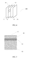
- a touchscreen of the terminal 200 includes: a basal layer 11, a first conductive layer 12, a second conductive layer 13, a touch layer 14, an antenna layer 15, and a separation layer 16.
- the antenna layer 15 and the separation layer 16 are disposed between the second conductive layer 13 and the touch layer 14.
- the basal layer 11, the first conductive layer 12, the second conductive layer 13, the touch layer 14, the antenna layer 15, and the separation layer 16 are disposed according to a sequence as follows: the basal layer 11, the first conductive layer 12, the second conductive layer 13, the separation layer 16, the antenna layer 15, and the touch layer 14.
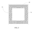
- the antenna layer 15 may include a visible area 31 and an invisible area 32.
- the visible area 31 may be made of glass or plastic with high light transmittance, so that light may transmit through the touchscreen.
- the invisible area 32 is configured to dispose the frequency modulation FM antenna.
- a groove may be provided in the invisible area 32, and the frequency modulation FM antenna may be disposed in the groove, so that the antenna layer has a smooth surface to closely attach to other layers.
- the antenna layer and the separation layer may be disposed in the first conductive layer or the second conductive layer.
- a touchscreen of the terminal 400 includes: a basal layer 11, a first conductive layer 12, a second conductive layer 13, a touch layer 14, an antenna layer 15, and a separation layer 16.
- the antenna layer 15 and the separation layer 16 are disposed in the first conductive layer 12.
- the first conductive layer 12 is divided into a first area 41, a second area 42, and a third area 43.
- the antenna layer 15 and the separation layer 16 are disposed in the first area 41 and the second area 42 of the first conductive layer 12 respectively, and the separation layer 16 in the second area 42 separates the antenna layer 15 in the first area 41 from the third area 43.
- the first area, the second area, and the third area do not specifically refer to a certain area of the first conductive layer. It is only required that an area where a separation layer is disposed can separate an area where an antenna layer is disposed from a remaining area of the first conductive layer.
- the first conductive layer 12 is still taken as an example for description.
- the third area 43 may be set to a visible area, and the first area 41 and the second area 42 are set to an invisible area.
- a groove may be provided in the third area 43 of the invisible area of the first conductive layer 12, and the frequency modulation FM antenna may be disposed in the groove, so that the first conductive layer 12 has a smooth surface to closely attach to other layers.
- the touchscreen is thinner, but an area for sensing a touch operation of a user becomes smaller.
- an area of the third area 43 is smaller than that of the first conductive layer 12.
- a second embodiment of the present invention provides a method for making a touchscreen of a terminal, where the method includes:
- the antenna layer and the separation may be attached between the basal layer and the first conductive layer, and the separation layer is configured to separate the antenna layer from the first conductive layer.
- the basal layer, the first conductive layer, the second conductive layer, the touch layer, the antenna layer, and the separation layer are disposed according to a sequence as follows: the basal layer, the antenna layer, the separation layer, the first conductive layer, the second conductive layer, and the touch layer.
- the antenna layer and the separation layer may be attached between the second conductive layer and the touch layer, and the separation layer is configured to separate the second conductive layer from the antenna layer.
- the basal layer, the first conductive layer, the second conductive layer, the touch layer, the antenna layer, and the separation layer are disposed according to a sequence as follows: the basal layer, the first conductive layer, the second conductive layer, the separation layer, the antenna layer, and the touch layer.
- the antenna layer 15 may be divided into a visible area 31 and an invisible area 32.
- the visible area 31 may be made of glass or plastic with high light transmittance, so that light may transmit through the touchscreen.
- the invisible area 32 is configured to dispose the frequency modulation FM antenna. Specifically, a groove may be provided in the invisible area 32, and the frequency modulation FM antenna may be disposed in the groove, so that the antenna layer has a smooth surface to closely attach to other layers.
- the antenna layer and the separation layer may be disposed in the first conductive layer or the second conductive layer.
- the first conductive layer is divided into a first area, a second area, and a third area.
- the antenna layer and the separation layer are disposed in the first area and the second area of the first conductive layer respectively, and the separation layer in the second area separates the antenna layer in the first area form the third area.
- the first conductive layer 12 is still taken as an example for description.
- an area where the third area 43 is located may be taken as a visible area
- an area where the first area 41 and the second area 42 are located may be taken as an invisible area.
- a groove may be provided in the third area 43 of the invisible area of the first conductive layer 12, and the frequency modulation FM antenna may be disposed in the groove, so that the first conductive layer 12 has a smooth surface to closely attach to other layers.
- a frequency modulation FM antenna is directly disposed on a touchscreen of a terminal, so that when using the frequency modulation FM antenna to receive an FM broadcast, a user does not need to carry earphones and is not limited by an environmental factor such as time and place, thereby improving flexibility for the terminal to receive an FM broadcast by using the frequency modulation FM antenna, and further enhancing user experience of using the terminal. Therefore, by adopting the technical solutions in the embodiments of the present invention, flexibility for a terminal to receive an FM broadcast by using a frequency modulation FM antenna is improved.
Landscapes
- Engineering & Computer Science (AREA)
- Theoretical Computer Science (AREA)
- General Engineering & Computer Science (AREA)
- Computer Hardware Design (AREA)
- Human Computer Interaction (AREA)
- General Physics & Mathematics (AREA)
- Physics & Mathematics (AREA)
- Multimedia (AREA)
- Computer Networks & Wireless Communication (AREA)
- Signal Processing (AREA)
- Telephone Set Structure (AREA)
- Support Of Aerials (AREA)
- Details Of Aerials (AREA)
- Variable-Direction Aerials And Aerial Arrays (AREA)
Abstract
Description
- The present invention relates to the field of communications technologies, and in particular, to a terminal and a method for making a touchscreen of the terminal.
- Currently, with the development of communications technologies, most mobile terminals are disposed with an FM (Frequency Modulation, frequency modulation) antenna. Generally, in order to well receive an FM broadcast on a frequency band from tens of megahertz to hundreds of megahertz, the frequency modulation FM antenna needs to be designed with a relatively large size. Therefore, a mobile terminal with an FM function usually takes earphones as the FM antenna.
- However, when a user uses the mobile terminal to receive an FM broadcast, the user must carry the earphones. In addition, in order to ensure that the mobile terminal provides a good reception effect, the earphones need to be unfolded or stretched, which leads to bad flexibility for the terminal to receive the FM broadcast by using the frequency modulation FM antenna.
- Embodiments of the present invention provide a terminal and a method for making the terminal, so as to improve flexibility for a terminal to receive an FM broadcast by using a frequency modulation FM antenna.
- The embodiments of the present invention adopt the following technical solutions:
- A terminal includes: a touchscreen; where the touchscreen includes: a basal layer, a first conductive layer, a second conductive layer, and a touch layer; and the touchscreen further includes: an antenna layer and a separation layer, where the antenna layer is configured to dispose a frequency modulation FM antenna; the antenna layer and the separation layer are disposed between the basal layer and the first conductive layer or between the second conductive layer and the touch layer; and the antenna layer and the first conductive layer or the second conductive layer are separated by using the separation layer; or
- Another terminal includes: a touchscreen; where the touchscreen includes: a basal layer, a first conductive layer, a second conductive layer, and a touch layer; and the touchscreen further includes: an antenna layer and a separation layer, where the antenna layer is configured to dispose a frequency modulation FM antenna; the first conductive layer or the second conductive layer is divided into a first area, a second area, and a third area; the antenna layer and the separation layer are disposed in the first area and the second area of the first conductive layer respectively, or the antenna layer and the separation layer are disposed in the first area and the second area of the second conductive layer respectively; and the separation layer in the second area separates the antenna layer in the first area from the third area.
- A method for making a touchscreen of a terminal includes:
- forming a basal layer, a first conductive layer, a second conductive layer, and a touch layer;
- forming an antenna layer and a separation layer, where the antenna layer is configured to dispose a frequency modulation FM antenna; and
- disposing the antenna layer and the separation layer between the basal layer and the first conductive layer or between the second conductive layer and the touch layer, and separating the antenna layer from the first conductive layer or the second conductive layer by using the separation layer.
- Another method for making a touchscreen of a terminal includes:
- forming a basal layer, a first conductive layer, a second conductive layer, and a touch layer; where the antenna layer is configured to dispose a frequency modulation FM antenna; and dividing the first conductive layer or the second conductive layer into a first area, a second area, and a third area, disposing the antenna layer and the separation layer in the first area and the second area of the first conductive layer respectively, or disposing the antenna layer and the separation layer in the first area and the second area of the second conductive layer respectively, and separating, by the separation layer in the second area, the antenna layer in the first area from the third area.
- In the terminal and the method for making a touchscreen of the terminal provided by the embodiments of the present invention, a frequency modulation FM antenna is directly disposed on a touchscreen of a terminal, so that when using the frequency modulation FM antenna to receive an FM broadcast, a user does not need to carry earphones and is not limited by an environmental factor such as time and place, thereby improving flexibility for the terminal to receive an FM broadcast by using the frequency modulation FM antenna. Therefore, by adopting the technical solutions in the embodiments of the present invention, flexibility for a terminal to receive an FM broadcast by using a frequency modulation FM antenna is improved.
- To illustrate the technical solutions in the embodiments of the present invention more clearly, accompanying drawings required for describing the embodiments are briefly introduced in the following. Apparently, the accompanying drawings in the following description merely show some embodiments of the present invention, and persons of ordinary skill in the art may still derive other drawings according to these accompanying drawings without creative efforts.
-
FIG. 1 is a schematic structural diagram of a terminal touchscreen according to a first embodiment of the present invention; -
FIG. 2 is another schematic structural diagram of a terminal touchscreen according to the first embodiment of the present invention; -
FIG. 3 is schematic structural diagram of an antenna layer of a terminal touchscreen according to the first embodiment of the present invention; -
FIG. 4 is another schematic structural diagram of a terminal touchscreen according to the first embodiment of the present invention; and -
FIG. 5 is a schematic structural diagram of a first conductive layer of a terminal touchscreen according to the first embodiment of the present invention. - The following clearly and completely describes the technical solutions in the embodiments of the present invention with reference to the accompanying drawings in the embodiments of the present invention. Apparently, the embodiments to be described are merely a part rather than all of the embodiments of the present invention. All other embodiments obtained by persons of ordinary skill in the art based on the embodiments of the present invention without creative efforts shall fall within the protection scope of the present invention.
- To improve user experience of using a terminal, a first embodiment of the present invention provides a terminal, including: a touchscreen. The touchscreen includes a basal layer, a first conductive layer, a second conductive layer, and a touch layer; and the touchscreen further includes an antenna layer and a separation layer, where the antenna layer is configured to dispose a frequency modulation FM antenna. The antenna layer may be made of a material same as that for making an FPC (Flexible Printed Circuit, flexible printed circuit), or may be a metal wire. It should be noted that, when a thickness of the antenna layer is designed, it is necessary to take account of a feature of the touchscreen disposed with the antenna layer. Generally, the antenna layer should better not be designed too thickly.
- The antenna layer and the separation layer are disposed between the basal layer and the first conductive layer; or the antenna layer and the separation layer are disposed between the second conductive layer and the touch layer; and the antenna layer is separated from the first conductive layer or the second conductive layer by using the separation layer.
- Or, the first conductive layer or the second conductive layer is divided into a first area, a second area, and a third area, where the antenna layer and the separation layer are disposed in the first area and the second area of the first conductive layer or the second conductive layer respectively, and the separation layer in the second area separates the antenna layer in the first area from the third area.
- In this embodiment, the terminal may be a phone, a PDA (Personal Digital Assistant, personal digital assistant), and a tablet, and so on.
- It may be seen from the foregoing description that, a frequency modulation FM antenna is directly disposed on a touchscreen of a terminal, so that when using the frequency modulation FM antenna to receive an FM broadcast, a user does not need to carry earphones and is not limited by an environmental factor such as time and place, thereby improving flexibility for the terminal to receive an FM broadcast by using the frequency modulation FM antenna, and further enhancing user experience of using the terminal. Therefore, by adopting the terminal in the embodiment of the present invention, flexibility for a terminal to receive an FM broadcast by using a frequency modulation FM antenna is improved.
- Specifically, according to a difference in positions where the antenna layer and the separation layer are disposed, the touchscreen of the terminal may include the following several different structures.
- Manner 1: As shown in
FIG. 1 , a touchscreen of theterminal 100 includes: abasal layer 11, a firstconductive layer 12, a secondconductive layer 13, atouch layer 14, anantenna layer 15, and aseparation layer 16. Theantenna layer 15 and theseparation layer 16 are disposed between thebasal layer 11 and the firstconductive layer 12. In this case, thebasal layer 11, the firstconductive layer 12, the secondconductive layer 13, thetouch layer 14, theantenna layer 15, and theseparation layer 16 are disposed according to a sequence as follows: thebasal layer 11, theantenna layer 15, theseparation layer 16, the firstconductive layer 12, the secondconductive layer 13, and thetouch layer 14. - Manner 2: As shown in
FIG. 2 , a touchscreen of theterminal 200 includes: abasal layer 11, a firstconductive layer 12, a secondconductive layer 13, atouch layer 14, anantenna layer 15, and aseparation layer 16. Theantenna layer 15 and theseparation layer 16 are disposed between the secondconductive layer 13 and thetouch layer 14. In this case, thebasal layer 11, the firstconductive layer 12, the secondconductive layer 13, thetouch layer 14, theantenna layer 15, and theseparation layer 16 are disposed according to a sequence as follows: thebasal layer 11, the firstconductive layer 12, the secondconductive layer 13, theseparation layer 16, theantenna layer 15, and thetouch layer 14. - Specifically, as shown in
FIG. 3 , in the manner 1 or the manner 2, theantenna layer 15 may include avisible area 31 and aninvisible area 32. Thevisible area 31 may be made of glass or plastic with high light transmittance, so that light may transmit through the touchscreen. Theinvisible area 32 is configured to dispose the frequency modulation FM antenna. Specifically, a groove may be provided in theinvisible area 32, and the frequency modulation FM antenna may be disposed in the groove, so that the antenna layer has a smooth surface to closely attach to other layers. - Manner 3: The antenna layer and the separation layer may be disposed in the first conductive layer or the second conductive layer.
- That the antenna layer and the separation layer are disposed in the first conductive layer is taken as an example. As shown in
FIG. 4 , a touchscreen of theterminal 400 includes: abasal layer 11, a firstconductive layer 12, a secondconductive layer 13, atouch layer 14, anantenna layer 15, and aseparation layer 16. Theantenna layer 15 and theseparation layer 16 are disposed in the firstconductive layer 12. - Specifically, as shown in
FIG. 5 , the firstconductive layer 12 is divided into afirst area 41, asecond area 42, and athird area 43. Theantenna layer 15 and theseparation layer 16 are disposed in thefirst area 41 and thesecond area 42 of the firstconductive layer 12 respectively, and theseparation layer 16 in thesecond area 42 separates theantenna layer 15 in thefirst area 41 from thethird area 43. The first area, the second area, and the third area do not specifically refer to a certain area of the first conductive layer. It is only required that an area where a separation layer is disposed can separate an area where an antenna layer is disposed from a remaining area of the first conductive layer. - In the manner 3, the first
conductive layer 12 is still taken as an example for description. Referring toFIG. 5 , thethird area 43 may be set to a visible area, and thefirst area 41 and thesecond area 42 are set to an invisible area. Similarly, a groove may be provided in thethird area 43 of the invisible area of the firstconductive layer 12, and the frequency modulation FM antenna may be disposed in the groove, so that the firstconductive layer 12 has a smooth surface to closely attach to other layers. - In addition, in the manner 3, when the antenna layer and the separation layer are disposed in the first conductive layer or the second conductive layer, the touchscreen is thinner, but an area for sensing a touch operation of a user becomes smaller. For example, in
FIG. 5 , an area of thethird area 43 is smaller than that of the firstconductive layer 12. - A second embodiment of the present invention provides a method for making a touchscreen of a terminal, where the method includes:
- successively forming a basal layer, a first conductive layer, a second conductive layer, and a touch layer;
- forming an antenna layer and a separation layer, where the antenna layer is configured to dispose a frequency modulation FM antenna; and
- disposing the antenna layer and the separation layer between the basal layer and the first conductive layer or between the second conductive layer and the touch layer, and separating the antenna layer from the first conductive layer or the second conductive layer by using the separation layer; or, dividing the first conductive layer or the second conductive layer into a first area, a second area, and a third area, and disposing the antenna layer and the separation layer in the first area and the second area of the first conductive layer or the second conductive layer respectively, and separating, by the separation layer in the second area, the antenna layer in the first area from the third area.
- In this embodiment, the antenna layer and the separation may be attached between the basal layer and the first conductive layer, and the separation layer is configured to separate the antenna layer from the first conductive layer. In this case, referring to
FIG. 1 , the basal layer, the first conductive layer, the second conductive layer, the touch layer, the antenna layer, and the separation layer are disposed according to a sequence as follows: the basal layer, the antenna layer, the separation layer, the first conductive layer, the second conductive layer, and the touch layer. - Or, the antenna layer and the separation layer may be attached between the second conductive layer and the touch layer, and the separation layer is configured to separate the second conductive layer from the antenna layer. In this case, referring to
FIG. 2 , the basal layer, the first conductive layer, the second conductive layer, the touch layer, the antenna layer, and the separation layer are disposed according to a sequence as follows: the basal layer, the first conductive layer, the second conductive layer, the separation layer, the antenna layer, and the touch layer. - Referring to
FIG. 3 , when the antenna layer and the separation layer are disposed between the basal layer and the first conductive layer, or disposed between the second conductive layer and the touch layer, theantenna layer 15 may be divided into avisible area 31 and aninvisible area 32. Thevisible area 31 may be made of glass or plastic with high light transmittance, so that light may transmit through the touchscreen. Theinvisible area 32 is configured to dispose the frequency modulation FM antenna. Specifically, a groove may be provided in theinvisible area 32, and the frequency modulation FM antenna may be disposed in the groove, so that the antenna layer has a smooth surface to closely attach to other layers. - Or, the antenna layer and the separation layer may be disposed in the first conductive layer or the second conductive layer. For example, referring to
FIG. 5 , the first conductive layer is divided into a first area, a second area, and a third area. The antenna layer and the separation layer are disposed in the first area and the second area of the first conductive layer respectively, and the separation layer in the second area separates the antenna layer in the first area form the third area. - When the antenna layer and the separation layer are disposed in the first conductive layer or the second conductive layer, the first
conductive layer 12 is still taken as an example for description. Referring toFIG. 5 , an area where thethird area 43 is located may be taken as a visible area, and an area where thefirst area 41 and thesecond area 42 are located may be taken as an invisible area. Similarly, a groove may be provided in thethird area 43 of the invisible area of the firstconductive layer 12, and the frequency modulation FM antenna may be disposed in the groove, so that the firstconductive layer 12 has a smooth surface to closely attach to other layers. - It may be seen from the foregoing description that, a frequency modulation FM antenna is directly disposed on a touchscreen of a terminal, so that when using the frequency modulation FM antenna to receive an FM broadcast, a user does not need to carry earphones and is not limited by an environmental factor such as time and place, thereby improving flexibility for the terminal to receive an FM broadcast by using the frequency modulation FM antenna, and further enhancing user experience of using the terminal. Therefore, by adopting the technical solutions in the embodiments of the present invention, flexibility for a terminal to receive an FM broadcast by using a frequency modulation FM antenna is improved.
- To sum up, by adopting the technical solutions in the embodiments of the present invention, flexibility for a terminal to receive an FM broadcast by using a frequency modulation FM antenna is improved.
- The foregoing description is merely specific implementation manners of the present invention, but is not intended to limit the protection scope of the present invention. Any variation or replacement readily figured out by persons skilled in the art within the technical scope disclosed in the present invention shall fall within the protection scope of the present invention. Therefore, the protection scope of the present invention shall be subject to the protection scope of the claims.
Claims (13)
- A terminal, comprising: a touchscreen; wherein the touchscreen comprises: a basal layer, a first conductive layer, a second conductive layer, and a touch layer; and the touchscreen further comprises: an antenna layer and a separation layer, wherein the antenna layer is configured to dispose a frequency modulation FM antenna; and the separation layer is configured to separate the antenna layer from the first conductive layer or the second conductive layer; and
the antenna layer and the separation layer are disposed between the basal layer and the first conductive layer or disposed between the second conductive layer and the touch layer. - The terminal according to claim 1, wherein when the antenna layer and the separation layer are disposed between the basal layer and the first conductive layer, the basal layer, the first conductive layer, the second conductive layer, the touch layer, the antenna layer, and the separation layer are disposed according to a sequence as follows:the basal layer, the antenna layer, the separation layer, the first conductive layer, the second conductive layer, and the touch layer.
- The terminal according to claim 1, wherein when the antenna layer and the separation layer are disposed between the touch layer and the second conductive layer, the basal layer, the first conductive layer, the second conductive layer, the touch layer, the antenna layer, and the separation layer are disposed according to a sequence as follows:the basal layer, the first conductive layer, the second conductive layer, the separation layer, the antenna layer, and the touch layer.
- The terminal according to any one of claims 1 to 3, wherein the antenna layer comprises a visible area and an invisible area.
- The terminal according to any one of claims 1 to 4, wherein the invisible area is configured to dispose the frequency modulation FM antenna.
- A terminal, comprising: a touchscreen; wherein the touchscreen comprises: a basal layer, a first conductive layer, a second conductive layer, and a touch layer; and the touchscreen further comprises: an antenna layer and a separation layer, wherein the antenna layer is configured to dispose a frequency modulation FM antenna; and
the first conductive layer or the second conductive layer is divided into a first area, a second area, and a third area; the antenna layer and the separation layer are disposed in the first area and the second area of the first conductive layer respectively; or the antenna layer and the separation layer are disposed in the first area and the second area of the second conductive layer respectively; and the separation layer in the second area separates the antenna layer in the first area from the third area. - The terminal according to claim 6, wherein the first area and the second area are an invisible area, and the third area is a visible area.
- The terminal according to any one of claims 6 to 7, wherein the basal layer, the first conductive layer, the second conductive layer, and the touch layer are disposed according to a sequence as follows: the basal layer, the first conductive layer, the second conductive layer, and the touch layer.
- A method for making a touchscreen of a terminal, comprising:forming a basal layer, a first conductive layer, a second conductive layer, and a touch layer;forming an antenna layer and a separation layer, wherein, the antenna layer is configured to dispose a frequency modulation FM antenna; and the separation layer is configured to separate the antenna layer from the first conductive layer or the second conductive layer; anddisposing the antenna layer and the separation layer between the basal layer and the first conductive layer or between the second conductive layer and the touch layer.
- The method according to claim 9, wherein the disposing the antenna layer and the separation layer between the basal layer and the first conductive layer or between the second conductive layer and the touch layer comprises:attaching the antenna layer and the separation layer between the basal layer and the first conductive layer, wherein the separation layer is configured to separate the antenna layer from the first conductive layer; andthe basal layer, the first conductive layer, the second conductive layer, the touch layer, the antenna layer, and the separation layer are attached according to a sequence as follows:the basal layer, the antenna layer, the separation layer, the first conductive layer, the second conductive layer, and the touch layer.
- The method according to claim 9, wherein the disposing the antenna layer and the separation layer between the basal layer and the first conductive layer or between the second conductive layer and the touch layer comprises:attaching the antenna layer and the separation layer between the second conductive layer and the touch layer, wherein the separation layer is configured to separate the second conductive layer from the antenna layer; andthe antenna layer and the separation layer are disposed between the touch layer and the second conductive layer, and the basal layer, the first conductive layer, the second conductive layer, the touch layer, the antenna layer, and the separation layer are attached according to a sequence as follows:the basal layer, the first conductive layer, the second conductive layer, the separation layer, the antenna layer, and the touch layer.
- A method for making a touchscreen of a terminal, comprising:forming a basal layer, a first conductive layer, a second conductive layer, and a touch layer; and dividing the first conductive layer or the second conductive layer into a first area, a second area, and a third area; disposing the antenna layer and the separation layer in the first area and the second area of the first conductive layer respectively, or disposing the antenna layer and the separation layer in the first area and the second area of the second conductive layer respectively, and separating, by the separation layer in the second area, the antenna layer in the first area from the third area, wherein the antenna layer is configured to dispose a frequency modulation FM antenna.
- The method according to claim 12, wherein the basal layer, the first conductive layer, the second conductive layer, and the touch layer are attached according to a sequence as follows: the basal layer, the first conductive layer, the second conductive layer, and the touch layer.
Applications Claiming Priority (1)
| Application Number | Priority Date | Filing Date | Title |
|---|---|---|---|
| PCT/CN2011/076783 WO2011137861A2 (en) | 2011-07-01 | 2011-07-01 | Terminal and method of manufacturing touch screen of terminal |
Publications (3)
| Publication Number | Publication Date |
|---|---|
| EP2728449A2 true EP2728449A2 (en) | 2014-05-07 |
| EP2728449A4 EP2728449A4 (en) | 2015-07-15 |
| EP2728449B1 EP2728449B1 (en) | 2018-12-26 |
Family
ID=44904145
Family Applications (1)
| Application Number | Title | Priority Date | Filing Date |
|---|---|---|---|
| EP11777280.6A Active EP2728449B1 (en) | 2011-07-01 | 2011-07-01 | Terminal with a touch screen including an fm antenna, and method of manufacturing the touchscreen |
Country Status (4)
| Country | Link |
|---|---|
| US (1) | US9484965B2 (en) |
| EP (1) | EP2728449B1 (en) |
| CN (1) | CN102308268A (en) |
| WO (1) | WO2011137861A2 (en) |
Cited By (5)
| Publication number | Priority date | Publication date | Assignee | Title |
|---|---|---|---|---|
| EP3206113A4 (en) * | 2014-10-09 | 2017-08-16 | ZTE Corporation | Touch screen and terminal |
| US10338742B2 (en) | 2017-03-02 | 2019-07-02 | Microsoft Technology Licensing, Llc | Detection method for a digitizer |
| US10730109B2 (en) | 2016-04-11 | 2020-08-04 | Stratasys Ltd. | Method and apparatus for additive manufacturing with powder material |
| US10994333B2 (en) | 2014-05-08 | 2021-05-04 | Stratasys Ltd. | Method and apparatus for 3D printing by selective sintering |
| US11400516B2 (en) | 2017-03-20 | 2022-08-02 | Stratasys Ltd. | Method and system for additive manufacturing with powder material |
Families Citing this family (6)
| Publication number | Priority date | Publication date | Assignee | Title |
|---|---|---|---|---|
| WO2015042335A1 (en) * | 2013-09-23 | 2015-03-26 | Apple Inc. | Electronic component embedded in ceramic material |
| KR102248849B1 (en) * | 2014-03-05 | 2021-05-07 | 삼성전자주식회사 | Antenna device and electronic device with the same |
| WO2015133842A1 (en) | 2014-03-05 | 2015-09-11 | Samsung Electronics Co., Ltd. | Antenna device and electronic device having the antenna device |
| US9813102B2 (en) * | 2014-12-15 | 2017-11-07 | Intel Corporation | Display panel with transparent conductor based isolator and method for improved wireless communications |
| KR102666192B1 (en) * | 2016-07-28 | 2024-05-14 | 삼성디스플레이 주식회사 | Display device |
| CN110392134B (en) * | 2018-04-20 | 2021-07-27 | Oppo广东移动通信有限公司 | Display screen assembly and electronic equipment |
Family Cites Families (18)
| Publication number | Priority date | Publication date | Assignee | Title |
|---|---|---|---|---|
| JP2007225644A (en) * | 2006-02-21 | 2007-09-06 | Epson Imaging Devices Corp | Method for manufacturing electrooptical device, electrooptical device, and electronic appliance |
| KR101393242B1 (en) * | 2007-04-04 | 2014-05-08 | 엘지전자 주식회사 | mobile terminal |
| KR20080113506A (en) * | 2007-06-25 | 2008-12-31 | 한플렉스 주식회사 | Touch panel device and method of preparing the same |
| KR100904960B1 (en) * | 2007-11-09 | 2009-06-26 | 엘지전자 주식회사 | Portable terminal |
| CN101620493B (en) * | 2008-06-30 | 2012-09-05 | 汉王科技股份有限公司 | Electromagnetic touch device of transparent antenna board |
| US8665164B2 (en) * | 2008-11-19 | 2014-03-04 | Apple Inc. | Multiband handheld electronic device slot antenna |
| US8102318B2 (en) * | 2009-03-10 | 2012-01-24 | Apple Inc. | Inverted-F antenna with bandwidth enhancement for electronic devices |
| US8963782B2 (en) * | 2009-09-03 | 2015-02-24 | Apple Inc. | Cavity-backed antenna for tablet device |
| US8773310B2 (en) * | 2010-03-30 | 2014-07-08 | Apple Inc. | Methods for forming cavity antennas |
| CN201773940U (en) * | 2010-07-06 | 2011-03-23 | 惠州Tcl移动通信有限公司 | Built-in FM antenna and mobile phone device thereof |
| CN201698380U (en) * | 2010-07-13 | 2011-01-05 | 上海晨兴希姆通电子科技有限公司 | Touch screen with radio built-in antenna and electronic device |
| US8760349B2 (en) * | 2010-11-26 | 2014-06-24 | Intel Corporation | Method and apparatus for in-mold laminate antennas |
| CN102156581A (en) * | 2011-04-07 | 2011-08-17 | 鸿富锦精密工业(深圳)有限公司 | Touch screen with integrated built-in antenna |
| WO2013009472A2 (en) * | 2011-07-11 | 2013-01-17 | Ning Alice | Conductive composites |
| US9246214B2 (en) * | 2012-03-08 | 2016-01-26 | Apple Inc. | Electronic device antenna structures with ferrite layers |
| WO2014036248A1 (en) * | 2012-09-01 | 2014-03-06 | Mophie, Inc. | Wireless communication accessory for a mobile device |
| US10164322B2 (en) * | 2014-08-27 | 2018-12-25 | Apple Inc. | Signal transmission system for electronic devices |
| US9793599B2 (en) * | 2015-03-06 | 2017-10-17 | Apple Inc. | Portable electronic device with antenna |
-
2011
- 2011-07-01 WO PCT/CN2011/076783 patent/WO2011137861A2/en active Application Filing
- 2011-07-01 EP EP11777280.6A patent/EP2728449B1/en active Active
- 2011-07-01 CN CN2011800013665A patent/CN102308268A/en active Pending
-
2013
- 2013-12-27 US US14/141,712 patent/US9484965B2/en active Active
Cited By (9)
| Publication number | Priority date | Publication date | Assignee | Title |
|---|---|---|---|---|
| US10994333B2 (en) | 2014-05-08 | 2021-05-04 | Stratasys Ltd. | Method and apparatus for 3D printing by selective sintering |
| EP3206113A4 (en) * | 2014-10-09 | 2017-08-16 | ZTE Corporation | Touch screen and terminal |
| US10008766B2 (en) | 2014-10-09 | 2018-06-26 | Zte Corporation | Touch screen and terminal |
| US10730109B2 (en) | 2016-04-11 | 2020-08-04 | Stratasys Ltd. | Method and apparatus for additive manufacturing with powder material |
| US11059100B2 (en) | 2016-04-11 | 2021-07-13 | Stratasys Ltd. | Method and apparatus for additive manufacturing with powder material |
| US11691196B2 (en) | 2016-04-11 | 2023-07-04 | Stratasys Ltd. | Method and apparatus for additive manufacturing with powder material |
| US11980941B2 (en) | 2016-04-11 | 2024-05-14 | Stratasys Ltd. | Method and apparatus for additive manufacturing with powder material |
| US10338742B2 (en) | 2017-03-02 | 2019-07-02 | Microsoft Technology Licensing, Llc | Detection method for a digitizer |
| US11400516B2 (en) | 2017-03-20 | 2022-08-02 | Stratasys Ltd. | Method and system for additive manufacturing with powder material |
Also Published As
| Publication number | Publication date |
|---|---|
| US20140113579A1 (en) | 2014-04-24 |
| WO2011137861A3 (en) | 2012-05-10 |
| US9484965B2 (en) | 2016-11-01 |
| WO2011137861A2 (en) | 2011-11-10 |
| CN102308268A (en) | 2012-01-04 |
| EP2728449B1 (en) | 2018-12-26 |
| EP2728449A4 (en) | 2015-07-15 |
Similar Documents
| Publication | Publication Date | Title |
|---|---|---|
| US9484965B2 (en) | Terminal and method for making touchscreen of terminal | |
| EP3651004B1 (en) | Mobile terminal | |
| CN106410428B (en) | Antenna device and electronic device including the same | |
| EP3041086B1 (en) | Antenna device and electronic device including the same | |
| EP3343693B1 (en) | Electronic device comprising antenna | |
| US10504481B2 (en) | Mobile terminal and method for controlling the same | |
| CN105846050B (en) | Antenna and electronic device with same | |
| EP3089021B1 (en) | Electronic device | |
| US10038245B2 (en) | Antenna module and mobile terminal having the same | |
| CN106575818B (en) | Antenna assembly and electronic equipment with the antenna assembly | |
| CN103367865B (en) | Manufacturing method of antenna and terminal device | |
| US9899728B2 (en) | Mobile terminal | |
| US10107952B2 (en) | Mobile terminal and method for controlling the same | |
| US9854077B2 (en) | Mobile terminal and method for controlling the same | |
| CN109375822B (en) | Touch screen, touch display screen and mobile terminal | |
| JP5649910B2 (en) | Mobile communication terminal | |
| KR20160024425A (en) | Electrical Device having Side Touch Area | |
| US10922511B2 (en) | Embedded fingerprint recognition device based on mobile terminal | |
| EP3206113A1 (en) | Touch screen and terminal | |
| US9304645B2 (en) | Manufacturing method of touch module | |
| CN110447002B (en) | Terminal | |
| KR102178805B1 (en) | Touch window | |
| CN103330361A (en) | Protection sleeve for electronic equipment, and electronic equipment | |
| CN104810601A (en) | Full metal frame antenna for handheld mobile terminal | |
| CN211478811U (en) | Polaroid, display screen and electronic equipment |
Legal Events
| Date | Code | Title | Description |
|---|---|---|---|
| PUAI | Public reference made under article 153(3) epc to a published international application that has entered the european phase |
Free format text: ORIGINAL CODE: 0009012 |
|
| 17P | Request for examination filed |
Effective date: 20131230 |
|
| AK | Designated contracting states |
Kind code of ref document: A2 Designated state(s): AL AT BE BG CH CY CZ DE DK EE ES FI FR GB GR HR HU IE IS IT LI LT LU LV MC MK MT NL NO PL PT RO RS SE SI SK SM TR |
|
| DAX | Request for extension of the european patent (deleted) | ||
| A4 | Supplementary search report drawn up and despatched |
Effective date: 20150616 |
|
| RIC1 | Information provided on ipc code assigned before grant |
Ipc: G06F 3/041 20060101AFI20150610BHEP |
|
| RAP1 | Party data changed (applicant data changed or rights of an application transferred) |
Owner name: HUAWEI DEVICE (DONGGUAN) CO., LTD. |
|
| GRAP | Despatch of communication of intention to grant a patent |
Free format text: ORIGINAL CODE: EPIDOSNIGR1 |
|
| STAA | Information on the status of an ep patent application or granted ep patent |
Free format text: STATUS: GRANT OF PATENT IS INTENDED |
|
| RIC1 | Information provided on ipc code assigned before grant |
Ipc: G06F 1/16 20060101ALI20180607BHEP Ipc: H01Q 1/44 20060101ALI20180607BHEP Ipc: G06F 3/041 20060101AFI20180607BHEP |
|
| INTG | Intention to grant announced |
Effective date: 20180710 |
|
| GRAS | Grant fee paid |
Free format text: ORIGINAL CODE: EPIDOSNIGR3 |
|
| GRAA | (expected) grant |
Free format text: ORIGINAL CODE: 0009210 |
|
| STAA | Information on the status of an ep patent application or granted ep patent |
Free format text: STATUS: THE PATENT HAS BEEN GRANTED |
|
| AK | Designated contracting states |
Kind code of ref document: B1 Designated state(s): AL AT BE BG CH CY CZ DE DK EE ES FI FR GB GR HR HU IE IS IT LI LT LU LV MC MK MT NL NO PL PT RO RS SE SI SK SM TR |
|
| REG | Reference to a national code |
Ref country code: GB Ref legal event code: FG4D |
|
| REG | Reference to a national code |
Ref country code: CH Ref legal event code: EP |
|
| REG | Reference to a national code |
Ref country code: AT Ref legal event code: REF Ref document number: 1082311 Country of ref document: AT Kind code of ref document: T Effective date: 20190115 |
|
| REG | Reference to a national code |
Ref country code: IE Ref legal event code: FG4D |
|
| REG | Reference to a national code |
Ref country code: DE Ref legal event code: R096 Ref document number: 602011055180 Country of ref document: DE |
|
| PG25 | Lapsed in a contracting state [announced via postgrant information from national office to epo] |
Ref country code: BG Free format text: LAPSE BECAUSE OF FAILURE TO SUBMIT A TRANSLATION OF THE DESCRIPTION OR TO PAY THE FEE WITHIN THE PRESCRIBED TIME-LIMIT Effective date: 20190326 Ref country code: LT Free format text: LAPSE BECAUSE OF FAILURE TO SUBMIT A TRANSLATION OF THE DESCRIPTION OR TO PAY THE FEE WITHIN THE PRESCRIBED TIME-LIMIT Effective date: 20181226 Ref country code: NO Free format text: LAPSE BECAUSE OF FAILURE TO SUBMIT A TRANSLATION OF THE DESCRIPTION OR TO PAY THE FEE WITHIN THE PRESCRIBED TIME-LIMIT Effective date: 20190326 Ref country code: HR Free format text: LAPSE BECAUSE OF FAILURE TO SUBMIT A TRANSLATION OF THE DESCRIPTION OR TO PAY THE FEE WITHIN THE PRESCRIBED TIME-LIMIT Effective date: 20181226 Ref country code: LV Free format text: LAPSE BECAUSE OF FAILURE TO SUBMIT A TRANSLATION OF THE DESCRIPTION OR TO PAY THE FEE WITHIN THE PRESCRIBED TIME-LIMIT Effective date: 20181226 Ref country code: FI Free format text: LAPSE BECAUSE OF FAILURE TO SUBMIT A TRANSLATION OF THE DESCRIPTION OR TO PAY THE FEE WITHIN THE PRESCRIBED TIME-LIMIT Effective date: 20181226 |
|
| REG | Reference to a national code |
Ref country code: NL Ref legal event code: MP Effective date: 20181226 |
|
| REG | Reference to a national code |
Ref country code: LT Ref legal event code: MG4D |
|
| PG25 | Lapsed in a contracting state [announced via postgrant information from national office to epo] |
Ref country code: AL Free format text: LAPSE BECAUSE OF FAILURE TO SUBMIT A TRANSLATION OF THE DESCRIPTION OR TO PAY THE FEE WITHIN THE PRESCRIBED TIME-LIMIT Effective date: 20181226 Ref country code: SE Free format text: LAPSE BECAUSE OF FAILURE TO SUBMIT A TRANSLATION OF THE DESCRIPTION OR TO PAY THE FEE WITHIN THE PRESCRIBED TIME-LIMIT Effective date: 20181226 Ref country code: RS Free format text: LAPSE BECAUSE OF FAILURE TO SUBMIT A TRANSLATION OF THE DESCRIPTION OR TO PAY THE FEE WITHIN THE PRESCRIBED TIME-LIMIT Effective date: 20181226 Ref country code: GR Free format text: LAPSE BECAUSE OF FAILURE TO SUBMIT A TRANSLATION OF THE DESCRIPTION OR TO PAY THE FEE WITHIN THE PRESCRIBED TIME-LIMIT Effective date: 20190327 |
|
| RAP2 | Party data changed (patent owner data changed or rights of a patent transferred) |
Owner name: HUAWEI DEVICE CO., LTD. |
|
| REG | Reference to a national code |
Ref country code: AT Ref legal event code: MK05 Ref document number: 1082311 Country of ref document: AT Kind code of ref document: T Effective date: 20181226 |
|
| REG | Reference to a national code |
Ref country code: DE Ref legal event code: R081 Ref document number: 602011055180 Country of ref document: DE Owner name: HONOR DEVICE CO., LTD., SHENZHEN, CN Free format text: FORMER OWNER: HUAWEI DEVICE (DONGGUAN) CO., LTD., DONGGUAN, GUANGDONG, CN |
|
| PG25 | Lapsed in a contracting state [announced via postgrant information from national office to epo] |
Ref country code: NL Free format text: LAPSE BECAUSE OF FAILURE TO SUBMIT A TRANSLATION OF THE DESCRIPTION OR TO PAY THE FEE WITHIN THE PRESCRIBED TIME-LIMIT Effective date: 20181226 |
|
| PG25 | Lapsed in a contracting state [announced via postgrant information from national office to epo] |
Ref country code: PT Free format text: LAPSE BECAUSE OF FAILURE TO SUBMIT A TRANSLATION OF THE DESCRIPTION OR TO PAY THE FEE WITHIN THE PRESCRIBED TIME-LIMIT Effective date: 20190426 Ref country code: IT Free format text: LAPSE BECAUSE OF FAILURE TO SUBMIT A TRANSLATION OF THE DESCRIPTION OR TO PAY THE FEE WITHIN THE PRESCRIBED TIME-LIMIT Effective date: 20181226 Ref country code: PL Free format text: LAPSE BECAUSE OF FAILURE TO SUBMIT A TRANSLATION OF THE DESCRIPTION OR TO PAY THE FEE WITHIN THE PRESCRIBED TIME-LIMIT Effective date: 20181226 Ref country code: CZ Free format text: LAPSE BECAUSE OF FAILURE TO SUBMIT A TRANSLATION OF THE DESCRIPTION OR TO PAY THE FEE WITHIN THE PRESCRIBED TIME-LIMIT Effective date: 20181226 Ref country code: ES Free format text: LAPSE BECAUSE OF FAILURE TO SUBMIT A TRANSLATION OF THE DESCRIPTION OR TO PAY THE FEE WITHIN THE PRESCRIBED TIME-LIMIT Effective date: 20181226 |
|
| PG25 | Lapsed in a contracting state [announced via postgrant information from national office to epo] |
Ref country code: SM Free format text: LAPSE BECAUSE OF FAILURE TO SUBMIT A TRANSLATION OF THE DESCRIPTION OR TO PAY THE FEE WITHIN THE PRESCRIBED TIME-LIMIT Effective date: 20181226 Ref country code: EE Free format text: LAPSE BECAUSE OF FAILURE TO SUBMIT A TRANSLATION OF THE DESCRIPTION OR TO PAY THE FEE WITHIN THE PRESCRIBED TIME-LIMIT Effective date: 20181226 Ref country code: IS Free format text: LAPSE BECAUSE OF FAILURE TO SUBMIT A TRANSLATION OF THE DESCRIPTION OR TO PAY THE FEE WITHIN THE PRESCRIBED TIME-LIMIT Effective date: 20190426 Ref country code: SK Free format text: LAPSE BECAUSE OF FAILURE TO SUBMIT A TRANSLATION OF THE DESCRIPTION OR TO PAY THE FEE WITHIN THE PRESCRIBED TIME-LIMIT Effective date: 20181226 Ref country code: RO Free format text: LAPSE BECAUSE OF FAILURE TO SUBMIT A TRANSLATION OF THE DESCRIPTION OR TO PAY THE FEE WITHIN THE PRESCRIBED TIME-LIMIT Effective date: 20181226 |
|
| REG | Reference to a national code |
Ref country code: DE Ref legal event code: R097 Ref document number: 602011055180 Country of ref document: DE |
|
| PG25 | Lapsed in a contracting state [announced via postgrant information from national office to epo] |
Ref country code: AT Free format text: LAPSE BECAUSE OF FAILURE TO SUBMIT A TRANSLATION OF THE DESCRIPTION OR TO PAY THE FEE WITHIN THE PRESCRIBED TIME-LIMIT Effective date: 20181226 Ref country code: DK Free format text: LAPSE BECAUSE OF FAILURE TO SUBMIT A TRANSLATION OF THE DESCRIPTION OR TO PAY THE FEE WITHIN THE PRESCRIBED TIME-LIMIT Effective date: 20181226 |
|
| PLBE | No opposition filed within time limit |
Free format text: ORIGINAL CODE: 0009261 |
|
| STAA | Information on the status of an ep patent application or granted ep patent |
Free format text: STATUS: NO OPPOSITION FILED WITHIN TIME LIMIT |
|
| 26N | No opposition filed |
Effective date: 20190927 |
|
| PG25 | Lapsed in a contracting state [announced via postgrant information from national office to epo] |
Ref country code: SI Free format text: LAPSE BECAUSE OF FAILURE TO SUBMIT A TRANSLATION OF THE DESCRIPTION OR TO PAY THE FEE WITHIN THE PRESCRIBED TIME-LIMIT Effective date: 20181226 Ref country code: MC Free format text: LAPSE BECAUSE OF FAILURE TO SUBMIT A TRANSLATION OF THE DESCRIPTION OR TO PAY THE FEE WITHIN THE PRESCRIBED TIME-LIMIT Effective date: 20181226 |
|
| REG | Reference to a national code |
Ref country code: CH Ref legal event code: PL |
|
| PG25 | Lapsed in a contracting state [announced via postgrant information from national office to epo] |
Ref country code: TR Free format text: LAPSE BECAUSE OF FAILURE TO SUBMIT A TRANSLATION OF THE DESCRIPTION OR TO PAY THE FEE WITHIN THE PRESCRIBED TIME-LIMIT Effective date: 20181226 |
|
| REG | Reference to a national code |
Ref country code: BE Ref legal event code: MM Effective date: 20190731 |
|
| PG25 | Lapsed in a contracting state [announced via postgrant information from national office to epo] |
Ref country code: BE Free format text: LAPSE BECAUSE OF NON-PAYMENT OF DUE FEES Effective date: 20190731 Ref country code: CH Free format text: LAPSE BECAUSE OF NON-PAYMENT OF DUE FEES Effective date: 20190731 Ref country code: LU Free format text: LAPSE BECAUSE OF NON-PAYMENT OF DUE FEES Effective date: 20190701 Ref country code: LI Free format text: LAPSE BECAUSE OF NON-PAYMENT OF DUE FEES Effective date: 20190731 |
|
| PG25 | Lapsed in a contracting state [announced via postgrant information from national office to epo] |
Ref country code: IE Free format text: LAPSE BECAUSE OF NON-PAYMENT OF DUE FEES Effective date: 20190701 |
|
| REG | Reference to a national code |
Ref country code: DE Ref legal event code: R081 Ref document number: 602011055180 Country of ref document: DE Owner name: HONOR DEVICE CO., LTD., SHENZHEN, CN Free format text: FORMER OWNER: HUAWEI DEVICE CO., LTD., DONGGUAN, GUANGDONG, CN |
|
| PG25 | Lapsed in a contracting state [announced via postgrant information from national office to epo] |
Ref country code: CY Free format text: LAPSE BECAUSE OF FAILURE TO SUBMIT A TRANSLATION OF THE DESCRIPTION OR TO PAY THE FEE WITHIN THE PRESCRIBED TIME-LIMIT Effective date: 20181226 |
|
| REG | Reference to a national code |
Ref country code: GB Ref legal event code: 732E Free format text: REGISTERED BETWEEN 20210624 AND 20210630 |
|
| PG25 | Lapsed in a contracting state [announced via postgrant information from national office to epo] |
Ref country code: MT Free format text: LAPSE BECAUSE OF FAILURE TO SUBMIT A TRANSLATION OF THE DESCRIPTION OR TO PAY THE FEE WITHIN THE PRESCRIBED TIME-LIMIT Effective date: 20181226 Ref country code: HU Free format text: LAPSE BECAUSE OF FAILURE TO SUBMIT A TRANSLATION OF THE DESCRIPTION OR TO PAY THE FEE WITHIN THE PRESCRIBED TIME-LIMIT; INVALID AB INITIO Effective date: 20110701 |
|
| PG25 | Lapsed in a contracting state [announced via postgrant information from national office to epo] |
Ref country code: MK Free format text: LAPSE BECAUSE OF FAILURE TO SUBMIT A TRANSLATION OF THE DESCRIPTION OR TO PAY THE FEE WITHIN THE PRESCRIBED TIME-LIMIT Effective date: 20181226 |
|
| PGFP | Annual fee paid to national office [announced via postgrant information from national office to epo] |
Ref country code: GB Payment date: 20240530 Year of fee payment: 14 |
|
| PGFP | Annual fee paid to national office [announced via postgrant information from national office to epo] |
Ref country code: FR Payment date: 20240611 Year of fee payment: 14 |
|
| PGFP | Annual fee paid to national office [announced via postgrant information from national office to epo] |
Ref country code: DE Payment date: 20240604 Year of fee payment: 14 |