EP2728202B1 - Pneumatisches Antriebssystem und Verfahren zum Betreiben des pneumatischen Antriebssystems - Google Patents
Pneumatisches Antriebssystem und Verfahren zum Betreiben des pneumatischen Antriebssystems Download PDFInfo
- Publication number
- EP2728202B1 EP2728202B1 EP13004695.6A EP13004695A EP2728202B1 EP 2728202 B1 EP2728202 B1 EP 2728202B1 EP 13004695 A EP13004695 A EP 13004695A EP 2728202 B1 EP2728202 B1 EP 2728202B1
- Authority
- EP
- European Patent Office
- Prior art keywords
- control
- pressure
- working chamber
- pneumatic
- control signal
- Prior art date
- Legal status (The legal status is an assumption and is not a legal conclusion. Google has not performed a legal analysis and makes no representation as to the accuracy of the status listed.)
- Active
Links
Images


Classifications
-
- F—MECHANICAL ENGINEERING; LIGHTING; HEATING; WEAPONS; BLASTING
- F16—ENGINEERING ELEMENTS AND UNITS; GENERAL MEASURES FOR PRODUCING AND MAINTAINING EFFECTIVE FUNCTIONING OF MACHINES OR INSTALLATIONS; THERMAL INSULATION IN GENERAL
- F16K—VALVES; TAPS; COCKS; ACTUATING-FLOATS; DEVICES FOR VENTING OR AERATING
- F16K31/00—Actuating devices; Operating means; Releasing devices
- F16K31/12—Actuating devices; Operating means; Releasing devices actuated by fluid
-
- F—MECHANICAL ENGINEERING; LIGHTING; HEATING; WEAPONS; BLASTING
- F15—FLUID-PRESSURE ACTUATORS; HYDRAULICS OR PNEUMATICS IN GENERAL
- F15B—SYSTEMS ACTING BY MEANS OF FLUIDS IN GENERAL; FLUID-PRESSURE ACTUATORS, e.g. SERVOMOTORS; DETAILS OF FLUID-PRESSURE SYSTEMS, NOT OTHERWISE PROVIDED FOR
- F15B5/00—Transducers converting variations of physical quantities, e.g. expressed by variations in positions of members, into fluid-pressure variations or vice versa; Varying fluid pressure as a function of variations of a plurality of fluid pressures or variations of other quantities
- F15B5/006—Transducers converting variations of physical quantities, e.g. expressed by variations in positions of members, into fluid-pressure variations or vice versa; Varying fluid pressure as a function of variations of a plurality of fluid pressures or variations of other quantities with electrical means, e.g. electropneumatic transducer
-
- G—PHYSICS
- G05—CONTROLLING; REGULATING
- G05B—CONTROL OR REGULATING SYSTEMS IN GENERAL; FUNCTIONAL ELEMENTS OF SUCH SYSTEMS; MONITORING OR TESTING ARRANGEMENTS FOR SUCH SYSTEMS OR ELEMENTS
- G05B19/00—Program-control systems
- G05B19/43—Program-control systems fluidic
- G05B19/44—Program-control systems fluidic pneumatic
-
- F—MECHANICAL ENGINEERING; LIGHTING; HEATING; WEAPONS; BLASTING
- F15—FLUID-PRESSURE ACTUATORS; HYDRAULICS OR PNEUMATICS IN GENERAL
- F15B—SYSTEMS ACTING BY MEANS OF FLUIDS IN GENERAL; FLUID-PRESSURE ACTUATORS, e.g. SERVOMOTORS; DETAILS OF FLUID-PRESSURE SYSTEMS, NOT OTHERWISE PROVIDED FOR
- F15B11/00—Servomotor systems without provision for follow-up action; Circuits therefor
- F15B11/02—Systems essentially incorporating special features for controlling the speed or actuating force of an output member
- F15B11/04—Systems essentially incorporating special features for controlling the speed or actuating force of an output member for controlling the speed
- F15B11/042—Systems essentially incorporating special features for controlling the speed or actuating force of an output member for controlling the speed by means in the feed line, i.e. "meter in"
- F15B11/0426—Systems essentially incorporating special features for controlling the speed or actuating force of an output member for controlling the speed by means in the feed line, i.e. "meter in" by controlling the number of pumps or parallel valves switched on
-
- F—MECHANICAL ENGINEERING; LIGHTING; HEATING; WEAPONS; BLASTING
- F15—FLUID-PRESSURE ACTUATORS; HYDRAULICS OR PNEUMATICS IN GENERAL
- F15B—SYSTEMS ACTING BY MEANS OF FLUIDS IN GENERAL; FLUID-PRESSURE ACTUATORS, e.g. SERVOMOTORS; DETAILS OF FLUID-PRESSURE SYSTEMS, NOT OTHERWISE PROVIDED FOR
- F15B2211/00—Circuits for servomotor systems
- F15B2211/30—Directional control
- F15B2211/305—Directional control characterised by the type of valves
- F15B2211/3056—Assemblies of multiple valves
- F15B2211/30565—Assemblies of multiple valves having multiple valves for a single output member, e.g. for creating higher valve function by use of multiple valves like two 2/2-valves replacing a 5/3-valve
-
- F—MECHANICAL ENGINEERING; LIGHTING; HEATING; WEAPONS; BLASTING
- F15—FLUID-PRESSURE ACTUATORS; HYDRAULICS OR PNEUMATICS IN GENERAL
- F15B—SYSTEMS ACTING BY MEANS OF FLUIDS IN GENERAL; FLUID-PRESSURE ACTUATORS, e.g. SERVOMOTORS; DETAILS OF FLUID-PRESSURE SYSTEMS, NOT OTHERWISE PROVIDED FOR
- F15B2211/00—Circuits for servomotor systems
- F15B2211/40—Flow control
- F15B2211/405—Flow control characterised by the type of flow control means or valve
- F15B2211/40576—Assemblies of multiple valves
- F15B2211/40592—Assemblies of multiple valves with multiple valves in parallel flow paths
-
- F—MECHANICAL ENGINEERING; LIGHTING; HEATING; WEAPONS; BLASTING
- F15—FLUID-PRESSURE ACTUATORS; HYDRAULICS OR PNEUMATICS IN GENERAL
- F15B—SYSTEMS ACTING BY MEANS OF FLUIDS IN GENERAL; FLUID-PRESSURE ACTUATORS, e.g. SERVOMOTORS; DETAILS OF FLUID-PRESSURE SYSTEMS, NOT OTHERWISE PROVIDED FOR
- F15B2211/00—Circuits for servomotor systems
- F15B2211/60—Circuit components or control therefor
- F15B2211/63—Electronic controllers
- F15B2211/6303—Electronic controllers using input signals
- F15B2211/6336—Electronic controllers using input signals representing a state of the output member, e.g. position, speed or acceleration
-
- F—MECHANICAL ENGINEERING; LIGHTING; HEATING; WEAPONS; BLASTING
- F15—FLUID-PRESSURE ACTUATORS; HYDRAULICS OR PNEUMATICS IN GENERAL
- F15B—SYSTEMS ACTING BY MEANS OF FLUIDS IN GENERAL; FLUID-PRESSURE ACTUATORS, e.g. SERVOMOTORS; DETAILS OF FLUID-PRESSURE SYSTEMS, NOT OTHERWISE PROVIDED FOR
- F15B2211/00—Circuits for servomotor systems
- F15B2211/60—Circuit components or control therefor
- F15B2211/665—Methods of control using electronic components
- F15B2211/6653—Pressure control
-
- F—MECHANICAL ENGINEERING; LIGHTING; HEATING; WEAPONS; BLASTING
- F15—FLUID-PRESSURE ACTUATORS; HYDRAULICS OR PNEUMATICS IN GENERAL
- F15B—SYSTEMS ACTING BY MEANS OF FLUIDS IN GENERAL; FLUID-PRESSURE ACTUATORS, e.g. SERVOMOTORS; DETAILS OF FLUID-PRESSURE SYSTEMS, NOT OTHERWISE PROVIDED FOR
- F15B2211/00—Circuits for servomotor systems
- F15B2211/60—Circuit components or control therefor
- F15B2211/665—Methods of control using electronic components
- F15B2211/6656—Closed loop control, i.e. control using feedback
-
- F—MECHANICAL ENGINEERING; LIGHTING; HEATING; WEAPONS; BLASTING
- F15—FLUID-PRESSURE ACTUATORS; HYDRAULICS OR PNEUMATICS IN GENERAL
- F15B—SYSTEMS ACTING BY MEANS OF FLUIDS IN GENERAL; FLUID-PRESSURE ACTUATORS, e.g. SERVOMOTORS; DETAILS OF FLUID-PRESSURE SYSTEMS, NOT OTHERWISE PROVIDED FOR
- F15B2211/00—Circuits for servomotor systems
- F15B2211/80—Other types of control related to particular problems or conditions
- F15B2211/885—Control specific to the type of fluid, e.g. specific to magnetorheological fluid
- F15B2211/8855—Compressible fluids, e.g. specific to pneumatics
-
- F—MECHANICAL ENGINEERING; LIGHTING; HEATING; WEAPONS; BLASTING
- F16—ENGINEERING ELEMENTS AND UNITS; GENERAL MEASURES FOR PRODUCING AND MAINTAINING EFFECTIVE FUNCTIONING OF MACHINES OR INSTALLATIONS; THERMAL INSULATION IN GENERAL
- F16K—VALVES; TAPS; COCKS; ACTUATING-FLOATS; DEVICES FOR VENTING OR AERATING
- F16K31/00—Actuating devices; Operating means; Releasing devices
- F16K31/12—Actuating devices; Operating means; Releasing devices actuated by fluid
- F16K31/122—Actuating devices; Operating means; Releasing devices actuated by fluid the fluid acting on a piston
- F16K31/124—Actuating devices; Operating means; Releasing devices actuated by fluid the fluid acting on a piston servo actuated
- F16K31/1245—Actuating devices; Operating means; Releasing devices actuated by fluid the fluid acting on a piston servo actuated with more than one valve
-
- F—MECHANICAL ENGINEERING; LIGHTING; HEATING; WEAPONS; BLASTING
- F16—ENGINEERING ELEMENTS AND UNITS; GENERAL MEASURES FOR PRODUCING AND MAINTAINING EFFECTIVE FUNCTIONING OF MACHINES OR INSTALLATIONS; THERMAL INSULATION IN GENERAL
- F16K—VALVES; TAPS; COCKS; ACTUATING-FLOATS; DEVICES FOR VENTING OR AERATING
- F16K31/00—Actuating devices; Operating means; Releasing devices
- F16K31/12—Actuating devices; Operating means; Releasing devices actuated by fluid
- F16K31/126—Actuating devices; Operating means; Releasing devices actuated by fluid the fluid acting on a diaphragm, bellows, or the like
- F16K31/128—Actuating devices; Operating means; Releasing devices actuated by fluid the fluid acting on a diaphragm, bellows, or the like servo actuated
Definitions
- the invention relates to a pneumatic drive system and a method for operating a pneumatic drive system.
- the pneumatic drive system is used to actuate a control valve, in particular a control valve or a safety shutdown valve (ESD valve), a process plant, such as a petrochemical plant or the like
- the pneumatic drive system of the generic type has a pneumatic working chamber and a current-pressure conversion coupled to the working chamber for pressurizing the working chamber with a pneumatic pressure through which the control valve is moved
- the current-pressure conversion has at least one electrical input for receiving an electrical control signal.
- the surge limit valve should be opened quickly, so that the performance of the compressor can be removed at the output. An overshoot of the surge relief valve is to be avoided to prevent dangerous operating conditions of the compressor.
- US 5,878,765 A relates to a microprocessor-controlled position controller.
- DE 10 2010 035 747 A1 discloses a valve unit with parallel 3/3-way proportional valve units.
- US 4,763,560 A relates to a method and apparatus for controlling and positioning a fluid actuator.
- a pneumatic drive system for actuating a control valve, in particular a control control valve or a safety valve of a process plant.
- the pneumatic drive system can be, for example, the type of single-acting pneumatic drive in which a pneumatic drive chamber and a spring-loaded return chamber can be formed within a drive housing. The two chambers can be separated by a membrane.
- a double-acting pneumatic drive can be provided which has to be acted upon above all with pneumatic pressure working chambers, which are separated from each other pneumatically by a movable adjusting cord.
- one of the chambers is considered according to the invention in the following.
- a current-pressure conversion is coupled, which acts on the working chamber with the pneumatic pressure through which the control valve is moved.
- the current-pressure transducer has at least one electrical input for receiving the electrical actuating signal.
- the current-pressure conversion is designed such that that at least two pneumatic control signals or control pressure signals are generated, with which the working chamber is acted upon.
- the current-pressure conversion in particular its electronics, have an activation and deactivation mechanism which activates and deactivates the respective pneumatic control signal or control pressure signal of the at least two pneumatic control signals or control pressure signals.
- the pneumatic control pressure signals are independent of each other and can be supplied to the working chamber the pressure amount after and the feed time different to the pneumatic working chamber of the pneumatic drive system.
- the current-pressure conversion generates the at least two actuating pressure signals independently of one another, in particular on the basis of two different actuating signals.
- the electrical control signal can be generated by a positioner or an electrical component of a positioner, which outputs the electrical control signal on the basis of a desired / actual value comparison, on the basis of which the respective pneumatic control signal is generated.
- the actual position value and the desired position value are supplied to the positioner.
- the current-pressure conversion leads the at least two pneumatic control signals independently of one another to the working chamber.
- the at least two control signals can be supplied suddenly or gradually to the maximum control pressure signal of the pneumatic working chamber.
- the current-pressure conversion leads to the at least two pneumatic control signals according to a predetermined or in particular regulated by a positioner, timing.
- the at least two pneumatic control pressure signals can be supplied to the working chamber alternately or successively, summing up or successively.
- the particular maximum amount of pressure of the at least two actuating pressure signals is preset. This can be achieved, for example, by using an I / P pressure converter module for the current pressure conversion of an actuating pressure signal, which can only give up a defined actuating pressure signal when a triggering electrical actuating signal is received.
- air flows of the at least two control signals are preset. This may mean that the current-pressure conversion causes the triggering and non-triggering of the control signals, which, when triggered, cause a predetermined air flow towards the working chamber.
- the air flow can be considered as volume flow or mass flow.
- the at least two actuating signals of the current-pressure conversion in particular one can have a low air flow and another a large air flow, wherein in particular the large flow is at least twice as large as the low air flow.
- the current-pressure conversion can be controlled and / or regulated such that for a quick displacement of the control valve, first the control signal with large air flow or both control signals with high and low air flow are supplied simultaneously. Only in a second control and / or regulating step, only the control signal with low air flow of the working chamber is then supplied according to the operation.
- one of the at least two control pressure signals is a low pressure signal and the other is a high pressure control signal.
- the high-pressure control signal is used to overcome a large control amplitude as quickly as possible, while the low-pressure control signal can be used to realize a fine adjustment of a position control specification.
- the high pressure control signal is at least twice as large as the low pressure control signal.
- the current-pressure conversion can be regulated in such a way that, for a rapid displacement of the control valve, at least the high-pressure control signal and then, in particular exclusively, the low-pressure control signal are supplied to the working chamber.
- the current-pressure conversion comprises control electronics, such as a microcomputer.
- the control electronics regulates based on a received setpoint value, which can be supplied, for example, from a control room to the pneumatic drive system, and optionally an actual control value, which is received by a position sensor, which may be part of the pneumatic drive system in particular, the generation and / or supply of at least two control pressure signals.
- the control electronics can be coupled according to regulations with at least two I / p transducers of the current-pressure conversion.
- the at least two I / p converters can operate independently of each other, generate the respective pneumatic control signal of the at least two control signals, in particular after receiving an electrical control signal of the control electronics specified before the respective I / p converter.
- the at least two I / p converters can be connected to a single compressed air source, preferably a constant supply pressure of, in particular, 6 bar.
- the control electronics has a clock or an activation and deactivation mechanism, which accesses the control of the respective I / p converter.
- the clock can be applied to the working chamber with the at least two pneumatic Timing signals clock in such a time that the control pressure signals are supplied simultaneously or successively superimposed or exclusive in a regular period of the working chamber.
- the control pressure signals can be preset according to their pressure amount, wherein the time sequence can represent a control parameter of the control electronics.
- the current-pressure conversion comprises a group consisting of two at least modular electronic components of different functionality and at least one modular slot for occupancy, each with an electron component.
- at least one electronic component is an I / p converter.
- the at least two electronic components of the group and the at least one slot are so modularly matched to each other that their electrical and optionally pneumatic interface on occupancy of the slot each functional and reliable pass each other.
- the interfaces of the electronic component used and the interface of the slot are diametrically opposite, so that an electrical contact and optionally a pneumatic, pressure loss coupling are made.
- the current-pressure conversion can also have electronic components that are not arranged in a modular slot.
- a modular slot is used to hold a singular modular electronic component.
- the at least one modular slot each has a modular docking mechanism for the at least one modular electronic component.
- the docking mechanism is designed to firmly hold and hold the respective electronic component in the modular slot, in particular by means of a catch, and if necessary to replace the electronic components, in particular non-destructively and preferably manually, in particular without special tools.
- the current-pressure conversion comprises at least two modular slots occupied by at least two I / P converters.
- a clock may be provided on a modular slot that activates and deactivates a respective I / P converter depending on the operating mode and operating state.
- the non-activated I / P converter in the slot remains in a passive wait position.
- the at least one slot has an electrical interface and optionally a pneumatic connected to the pneumatic supply input of the pneumatic drive system Interface for the pneumatic coupling of a pneumatic connection of the I / p converter.
- the current-pressure conversion has at least two pneumatically separated pneumatic outputs, which are connected to the one working chamber.
- a pneumatic control signal of the at least two control signals can leave the current-pressure conversion separately from each other.
- the at least two pneumatic outputs can each be formed by a single output of an I / p converter.
- a line network with at least two parallel lines connects.
- the at least two parallel lines each lead a control signal to the pneumatic working chamber.
- a separate parallel line can be connected to the at least two pneumatic separate pneumatic outputs, each of which in particular opens into the working chamber in each case at its own opening, which is formed in a drive housing delimiting the working chamber.
- the parallel lines may open into a main supply line leading into the working chamber.
- the at least two control signals arrive at the merging point of the main supply line and can be combined with simultaneous admission. In the respective lines, the control signals can pass completely unaffected by the current-pressure transducer into the working chamber.
- the respective, emanating from the current-pressure conversion control signals along the respective line can be changed operationally, for example by the line pneumatic components, such as a quick exhaust fan, a pneumatic switch, or an air power amplifier (booster) can be used.
- the line pneumatic components such as a quick exhaust fan, a pneumatic switch, or an air power amplifier (booster) can be used.
- boost air power amplifier
- the invention relates to a method for operating a pneumatic drive system for actuating a control valve, in particular the control valve or a safety valve, a process plant according to claim 8.
- the inventive method may be designed according to the operation of the pneumatic drive system according to the invention.
- a pneumatic working chamber is subjected to pneumatic pressure to move the control valve in a desired position.
- two or more pneumatic control signals are supplied to a working chamber of the pneumatic drive system by means of electropneumatic conversion.
- two pneumatic control signals of the one and the other pneumatic working chamber can be supplied in each case. In this case, four control signals are to be generated.
- each control signal or control signal is generated by an individual current-pressure conversion procedure.
- the control signals or control pressure signals are superimposed or exclusive, fed simultaneously or successively in the one working chamber.
- the at least two control signals are provided with different amounts of pressure, wherein in particular when exceeding a setpoint change limit of a position control procedure and / or triggering a setpoint change only a high pressure control signal is output to the one working chamber.
- the high-pressure control signal can follow the low-pressure control signal, in particular for fine-tuning the regulation of the pneumatic pressure, in particular in the working chamber.
- a low pressure control signal is delivered to a working chamber to avoid overshooting of the control valve.
- the air flows of the at least two control pressure signals are preset.
- the preset air flows are released when the respective control signal is triggered, without the possibility of changing them when dispensing.
- one of the at least two actuating signals is provided with a low airflow and another with a high airflow, wherein in particular the high airflow is at least twice as high as the low airflow.
- the control signal with high air flow or both control signals with high and low air flow and then only the control signal with low air flow to the working chamber supplied.
- the at least two control signals are provided with different sized air flows for regulating the position of the control valve.
- the at least two pneumatic control signals can be simultaneously fed to the working chamber.
- the control valve is switched off with high air flow while maintaining the switching position of the control valve with low air flow, and optionally after exceeding the allowable limits, the control signal is switched on with high air flow again.
- control valve in particular a surge limit
- two control signals in particular with different sized pressure amounts simultaneously supplied to a working chamber during a preferably pre-determined pulse period, in particular less than one second or until the control valve responds.
- one of the control signals in particular the high-pressure control signal, switches off, because then only a low pressure control signal should act.
- the length of the pulse period can be set, for example, from experience references to identical or similar control valves.
- the at least two control signals are provided with different sized pressure amounts, wherein the at least two pneumatic control signals are simultaneously fed to a working chamber.
- the high pressure control signal is switched off while maintaining the Niederbuchstellsignals and optionally switched to below the permissible limit, the high pressure control signal again.
- the at least two control pressure signals are provided with different amounts of pressure or air flows, in particular only the high-pressure control signal or the control signal is switched on with high air flow and / or to perform a partial stroke tests only to open or close a safety valve Low pressure control signal or control signal is switched on with low air flow.
- the volume supplied for a rapid regulation of the pressure in a volume, such as the working chamber or a supply line, at a large setpoint change at least two pneumatic signals simultaneously, at least over a short period of time after the setpoint change, the volume supplied.
- the signals may each comprise one or more high-pressure and low-pressure control signals, which in particular cause different volume flows.
- the volume With a small setpoint change, the volume can only be subjected to a set pressure signal, in particular a low pressure set signal. If the volume is supplied with at least two pneumatic control signals, the high-pressure control signal can be switched off in time before the low-pressure control signal, in particular as soon as a preferably predetermined pressure threshold value close to the desired value is reached in the volume. A fine adjustment of the pressure in the volume can be done by controlling the low pressure signal.
- a valve position of a valve such as a surge limit control valve for protecting a compressor
- rapid regulation of a valve position of a valve is achieved by simultaneously actuating the output valve with two pneumatic signals to open an output valve of the compressor.
- a Hochdruckstellsignal be performed at least until the response of the valve opening movement to the pneumatic drive, so that the output of the compressor as soon as possible unlocked and the compressor is not overloaded.
- the high-pressure control signal can be switched off after the response in order to avoid overshooting over the desired valve position.
- the low pressure control signal can be used.
- the low-pressure control signal is supplied to the pneumatic drive to safely avoid a dangerous condition of the compressor.
- two different control pressure signals are fed to the pneumatic drive for precise control of a valve position of a valve with pneumatic drive.
- a Hochdruckstelldrucksignal is thereby applied only for a short pulse duration simultaneously with a second control signal on the pneumatic drive.
- the short impulse with high volume flow quickly overcomes the static friction of the valve.
- the pulse length in a reference opening operation is determined as the period of time between the pressurization of the pneumatic drive and the tearing of the valve.
- the high-pressure control signal can, in particular time-controlled, safely be switched off in good time, without feedback of the valve position would have to occur, so that overshoot avoided and rapid control are ensured.
- the high pressure control signal may also be applied over the pulse duration Be used to control the valve position, however, is switched off before the second set pressure signal.
- valve position of a valve with pneumatic drive by two control pressure signals is controlled. If an oscillation tendency, for example by pressure surge excitations from the process medium, is detected, a control pressure signal, preferably the high-pressure control signal can be switched off or only a signal for controlling the valve can be supplied to the pneumatic drive. As soon as it is detected that the vibrations no longer occur, both signal pressure signals can be used again for valve position control.
- a high-pressure control signal or two control pressure signals are used for quickly opening or closing a safety valve.
- the mobility of the safety valve is ensured in a safety-critical operating situation in that a control pressure signal, in particular a low pressure control signal is applied to the pneumatic drive for actuating the safety valve and thereby a partial stroke test (partial stroke test), in particular between a 100% open position and 80% Opening position of the safety valve is performed.
- FIG. 1 is a pneumatically operated, inventive drive system generally provided with the reference numeral 1.
- a control valve 5 is actuated, which for controlling a process fluid flow of a process-technical, not shown Plant, such as a petrochemical plant, a food processing plant, such as a building, or the like is used.
- the control valve may also be a surge limit valve of a compressor or a safety shut-off valve.
- the pneumatic drive system 1 comprises a pneumatic actuator 4 with a working chamber 3, which acts on the control valve 5 for controlling the process fluid flow of the process plant, not shown, and a current-pressure conversion 7, which is designed as a positioner and to which a pneumatic line system 11 for Connection with the working chamber 3 of the actuator 4 connects.
- the control valve 5 is connected to the pneumatic actuator 4 via a spindle or shaft 13.
- the position sensor 15 outputs a position signal to a microprocessor 21, which is accommodated as shown in an interior of the housing 17 and receives a setpoint signal w via a field input 18 from a control center, not shown, of the process plant.
- the current-pressure conversion to a pneumatic field input 33 which is connected to a pneumatic supply source 31, and four outputs A 1-4 , which the pneumatic or electrical output signals S 1-4 of the plug-in or insertion slots 23 a, 23b, 23c, 23d externally provide the current-pressure conversion 7.
- the current-pressure conversion 7 or the positioner has four, essentially the same design, freely accessible from the outside plug-in or insertion slots 23a, 23b, 23c, 23d, which can optionally be assigned with four individual electronic components of different designs.
- the electronic component may be an I / P converter, a data memory, a pneumatically operated power generator, the microprocessor 21 and / or an electronic switch, whereby electronic components of the same design different functioning or performance parameters can be used in the slots.
- the slots 23a to 23d are modularly adapted such that, depending on which predetermined electronic component is used, they ensure the function of the electronic component by producing communication lines to the respective other components.
- the slots 23a to 23d have a pneumatic input interface 25a to 25d connected to a supply line 27 and electrical input interfaces 35a to 35d connected to the microprocessor 21 and output interfaces 33a to 32b 33d.
- Each slot 23a to 23d also has an output interface 37a to 37d through which output signals of either electrical nature (not in FIG. 1 shown) or pneumatic nature S 1-4 can be delivered to the respective output A 1 to A 4 .
- four I / p converter are provided in the slots 23a to 23d, the output via the outputs 1-4 pneumatic control signals S 1-4 .
- the pneumatic outputs A 1-4 lead 3rd Although not shown, one or two outputs can also separate lines directly with one or more working chambers of an actuator connected to a common line 41 for driving the working chamber.
- the slots 23a to 23d may also be occupied by four most different I / P converters. If a slot 23a to 23d is occupied by an I / P converter, the microprocessor 21 recognizes the occupancy via, for example, a suitable sensor, not shown, and / or via the respective electrical input interface 35a to 35d to the electrical microprocessor output O 1-4 connecting line.
- I / p converter By four separate inserted into the slots 23a to 23d I / p converter can be an actuator circuit with four decoupled control pressure signals achieve that realize common control and the same respective air flow of the I / p converter a quadruple-supplied air line.
- the control valve can be comparatively quickly bring the desired position even with large loads, which can be turned off for fine control on demand one, two or three control pressure signals to avoid any overshoot when starting the desired control position.
- the microprocessor 21 can select one of these for operation of the actuator 3 or simultaneously control several. Selects the microprocessor 21, for example, the arranged in the slot 23c I / P converter with a certain air power, the microprocessor 21 outputs, via its output I 3 from a corresponding electrical control signal to the disposed in the slot 23c I / P converter, which emits a corresponding air pressure signal S 3 via the pneumatic output interface 37c to the pneumatic actuator 3, wherein the remaining I / P converter in the slots 23a, 23b, 23d disabled by the microprocessor 21 or at least remain unaffected.
- I / P converters instead of a plurality of I / P converters, other components of the current-pressure conversion may be used in the slot 23a to 23d, such as the microprocessor 21, a data memory, a radio module or an electrical circuit for communication with external electrical components.
- the I / p converters 55a, 55b, 55c generate three pneumatic actuating pressure signals S 1-3 .
- the signal pressure signal S 1 is fed directly to the supply line of the actuator 3.
- the signal pressure signal S 2 is amplified by a volume amplifier 61 and coupled as a signal with a larger volume flow to the feed line of the actuator 3.
- the third actuating pressure signal S 3 essentially serves the purpose of switching a quick-action ventilator 63 for the actuator 3, which at a predetermined signal pressure signal drop at the output A 3 leads to venting of the pneumatic lines to the actuator 3.
- the current pressure conversion 7 is designed such that in the slot 23a, an electrical output stage 65 is arranged for driving a solenoid valve 67. Furthermore, two I / p converters 55b, 55c are inserted in the slots 23b and 23c. The outputs A 2-3 of the I / P converters 55b, 55c are coupled in a common supply line to the actuator 3. In the fourth slot 23d, a data memory M is provided by way of example.
- the solenoid valve 67 can be controlled so that the control pressure signals S 2-3 of the I / p converter can be passed to the actuator or for venting the actuator.
- the actuating pressure signal fed to the actuator when the solenoid valve 67 is switched on can comprise only one of the actuating pressure signals S 2 and S 3 or a combination of the two actuating pressure signals S 2 and S 3 .
- one of the control pressure signals is designed as a high-pressure signal and one of the control pressure signals as a low-pressure control signal in order to achieve greater variability in the control of the actuator.
- equal control pressure signals or one or more high pressure and / or low pressure control signals may be combined or fed as pairs of one high pressure and one low pressure control signal to one or more working chambers.
- a rapid pressure control in the drive chamber of the actuator 3 can be done.
- a pressure sensing component may optionally be provided in one of the slots 23a to 23d.
- rapid pressure adaptation can be achieved, for example, in that a plurality of control pressure signals are fed to the actuator, for example all control pressure signals S 1-4 in accordance with FIG FIG. 1 or the signal S 2 , large volume flow, with the signal S 1 according to FIG. 2 or both actuating pressure signals S 2-3 according to FIG. 3 ,
- one of the pressure signals in the case of unequal pressure signals that larger volume flow, can be switched on only for a short period of time, and the fine regulation essentially takes place via the further signal pressure signal.
- a low-pressure control signal or a small-volume flow signal can be used.
- other signal combinations may be advantageous, e.g. fast pressure change with three signals and fine control with two signals or one signal.
- a rapid control of the valve position of the control valve 5, for example, according FIG. 2 can be achieved, to quickly overcome the valve travel, a large volume flow is achieved by combining the amplified control pressure signal S 2 with the control signal S 1 , and the fine control with reduction of the flow through the unamplified signal S 1 takes place.
- Simultaneous control with two actuating pressure signals S 2-3 help to overcome the static friction in a valve and thus reduce the delay time resulting from the sticking, which usually complicates the regulation.
- One of the control pressure signals is switched off after overcoming the static friction by deactivating the I / p converter.
- the time of overcoming the static friction can be determined by a reference experiment and stored in the microprocessor or by appropriate measurement technology, which can also be provided as a module in a slot.
- the final fine control of the valve position is based on a control pressure signal, namely the low pressure control signal.
- the rule reliability with the arrangement according to the embodiment of FIG. 3 be improved in that in a fast position control using both control pressure signals S 2-3 in the case of a vibration excitation by the process medium of a the control pressure signals is switched off and the control exclusively on the basis of only one signal, usually the Niederbuchstellsignals, takes place until the tendency to oscillate has decreased.
Landscapes
- Engineering & Computer Science (AREA)
- General Engineering & Computer Science (AREA)
- Mechanical Engineering (AREA)
- Physics & Mathematics (AREA)
- Fluid Mechanics (AREA)
- General Physics & Mathematics (AREA)
- Automation & Control Theory (AREA)
- Fluid-Pressure Circuits (AREA)
- Fluid-Driven Valves (AREA)
Description
- Die Erfindung betrifft ein pneumatisches Antriebssystem und ein Verfahren zum Betreiben eines pneumatischen Antriebssystems. Das pneumatische Antriebssystem dient dazu, ein Stellventil, insbesondere ein Regelungsventil oder ein Sicherheitsventil (Emergency Shut Down (ESD-Ventil), einer prozesstechnischen Anlage, wie einer petrochemischen Anlage oder dergleichen, zu betätigen. Das pneumatische Antriebssystem der gattungsgemäßen Art hat eine pneumatische Arbeitskammer und eine mit der Arbeitskammer gekoppelte Strom-Druckwandlung zum Beaufschlagen der Arbeitskammer mit einem Pneumatikdruck, durch den das Stellventil verfahren wird. Die Strom-Druckwandlung hat wenigstens einen elektrischen Eingang zum Empfangen eines elektrischen Stellsignals.
- In vielen Anwendungsgebieten des pneumatischen Antriebssystems der gattungsgemäßen Art kommt es darauf an, dass eine gewünschte Stellung für das Stellventil anhand einer Soll-IstWert-Regelung schnell und zuverlässig erreicht wird. Aufgrund der Kraftübertragung mittels Pneumatik neigt das Antriebssystem dazu, die Sollstellung zu überschwingen und die gewünschte Position erst nach einer Verzugszeit zu erreichen.
- Beispielsweise im Falle des Einsatzes des pneumatischen Antriebsystems bei einem Pumpgrenzregelventil zum Schutz eines Kompressors kommt es darauf an, dass die gewünschte Ventilstellung schnell erreicht wird, wobei eine präzise Stellungsregelung gewährleistet sein soll. Um den ungewünschten Betriebszustand des "Pumpens" des Kompressors zu vermeiden, soll das Pumpgrenzventil schnell geöffnet werden, so dass die Leistung des Kompressors am Ausgang abgenommen werden kann. Ein Überschwingen des Pumpgrenzventils ist zu vermeiden, um gefährliche Betriebszustände des Kompressors zu unterbinden.
- Bei Stellungsregelungen für Stellventile, die keinem frequenten Betrieb unterworfen sind, kann es dazu kommen, dass das Ventilglied an der Dichtfläche des Ventilsitzes haften bleibt. Dabei muss von dem pneumatischen Antriebsystem eine größere Kraft aufgewendet werden, um das Ventilglied an dem Ventilsitz zu lösen. Die dabei auftretende Verzugszeit problematisiert eine schnelle und exakte Regelung. Ist das Stellventil dazu eingesetzt, ein Prozessmedium der prozesstechnischen Anlage zu regeln, neigt das Stellventil aufgrund von Anregung durch das Prozessmedium zu Schwingungen. Diese Schwingungen machen eine exakte Regelung des Prozessmediums schwierig.
-
US 5,878,765 A betrifft einen durch einen Mikroprozessor gesteuerten Positionsregler. -
DE 10 2010 035 747 A1 offenbart eine Ventileinheit mit parallel geschalteten 3/3-Wege-Proportionalventileinheiten. -
US 4,763,560 A betrifft ein Verfahren und eine Vorrichtung zum Steuern und Positionieren eines Fluidaktuators. - Es ist Aufgabe der Erfindung, die Nachteile des Stands der Technik zu überwinden, insbesondere ein pneumatisches Antriebssystem zum Betätigen eines Stellventils und ein Verfahren zum Betreiben des pneumatischen Antriebssystems bereitzustellen, mit dem eine schnelle und exakte Stellungsregelung erreicht werden kann.
- Diese Aufgabe wird durch die Merkmale von Anspruch 1 bzw. 8 gelöst.
- Danach ist ein pneumatisches Antriebssystem zum Betätigen eines Stellventils, insbesondere eines Regelungs-Stellventils oder eines Sicherheitsventils einer prozesstechnischen Anlage vorgesehen. Das pneumatische Antriebssystem kann beispielsweise der Typ eines einfach wirkenden pneumatischen Antriebs sein, bei dem innerhalb eines Antriebsgehäuses eine pneumatische Antriebskammer und eine mit Federn beaufschlagte Rückstellkammer ausgebildet sein kann. Die beiden Kammern können durch eine Membran voneinander getrennt sein. Als weiterer Antriebstyp kann auch ein doppelt wirkender Pneumatikantrieb vorgesehen sein, der vor allem mit Pneumatikdruck zu beaufschlagende Arbeitskammern aufweist, welche durch eine bewegliche Stellkordel voneinander pneumatisch getrennt sind. Bei dem doppelt wirkenden Pneumatikantrieb wird im Folgenden eine der Kammern erfindungsgemäß angesehen. Es können auch beide mit der erfindungsgemäßen Maßnahme beaufschlagt sein. Mit der pneumatischen Arbeitskammer ist eine Strom-Druckwandlung gekoppelt, die die Arbeitskammer mit dem Pneumatikdruck beaufschlagt, durch den das Stellventil verfahren wird. Der Strom-Druckwandler hat wenigstens einen elektrischen Eingang zum Empfangen des elektrischen Stellsignals. Erfindungsgemäß ist die Strom-Druckwandlung derart ausgelegt, dass wenigstens zwei pneumatische Stellsignale oder Stelldrucksignale erzeugt werden, mit denen die Arbeitskammer beaufschlagt ist. Je nach Betriebszustand kann die Strom-Druckwandlung, insbesondere deren Elektronik, einen Aktivierungs- und Deaktivierungsmechanismus aufweisen, der das jeweilige pneumatische Stellsignal oder Stelldrucksignal der wenigstens zwei pneumatischen Stellsignale oder Stelldrucksignale aktiviert und deaktiviert. Die pneumatischen Stelldrucksignale sind unabhängig voneinander und können der Arbeitskammer dem Druckbetrage nach sowie dem Zuführzeitpunkt unterschiedlich an die pneumatische Arbeitskammer des pneumatischen Antriebssystems zugeführt werden.
- Bei einer Weiterbildung der Erfindung erzeugt die Strom-Druckwandlung die wenigstens zwei Stelldrucksignale unabhängig voneinander, insbesondere auf der Basis von zwei unterschiedlichen Stellsignalen. Das elektrische Stellsignal kann von einem Stellungsregler oder einer Elektrokomponente eines Stellungsreglers generiert sein, der auf der Basis eines Soll-/Ist-Wertvergleichs das elektrische Stellsignal abgibt, auf deren Basis das jeweilige pneumatische Stellsignal erzeugt wird. Der Ist-Stellungswert und der Soll-Stellungswert werden dem Stellungsregler zugeführt.
- Bei einer Weiterbildung der Erfindung führt die Strom-Druckwandlung die wenigstens zwei pneumatischen Stellsignale unabhängig voneinander der Arbeitskammer zu. Die wenigstens zwei Stellsignale können sprungartig oder allmählich zu dem maximalen Stelldrucksignal der pneumatischen Arbeitskammer zugeführt werden.
- Bei einer Weiterbildung der Erfindung führt die Strom-Druckwandlung die wenigstens zwei pneumatischen Stellsignale gemäß einer vorgegebenen oder insbesondere durch einen Stellungsregler geregelten, zeitlichen Taktung zu. Dabei können die wenigstens zwei pneumatischen Stelldrucksignale gleichzeitig oder nacheinander aufsummierend oder nacheinander abwechselnd der Arbeitskammer zugeführt werden.
- Bei einer Weiterbildung der Erfindung ist der insbesondere maximale Druckbetrag der wenigstens zwei Stelldrucksignale voreingestellt. Dies kann beispielsweise dadurch erreicht werden, dass für die Stromdruck-Wandlung eines Stelldrucksignals ein I/p-Druckwandlerbaustein herangezogen wird, der lediglich ein festgelegtes Stelldrucksignal aufgeben kann, wenn ein auslösendes elektrisches Stellsignal empfangen wird.
- Vorzugsweise sind Luftdurchflüsse der wenigstens zwei Stellsignale voreingestellt. Dies kann bedeuten, dass die Strom-Druckwandlung das Auslösen und Nicht-Auslösen der Stellsignale veranlasst, die, wenn ausgelöst, einen vorbestimmten Luftdurchfluss hin zur Arbeitskammer veranlassen. Der Luftdurchfluss kann als Volumenstrom oder Massenstrom angesehen werden. Von den wenigstens zwei Stellsignalen der Strom-Druckwandlung kann insbesondere eines einen geringen Luftdurchfluss und ein anderes einen großen Luftdurchfluss aufweisen, wobei insbesondere der große Durchfluss wenigstens doppelt so groß wie der geringe Luftdurchfluss ist. Vorzugsweise kann die Strom-Druckwandlung derart gesteuert und/oder geregelt sein, dass für eine Schnellverlagerung des Stellventils zuerst das Stellsignal mit großem Luftdurchfluss oder beide Stellsignale mit großem und niedrigem Luftdurchfluss gleichzeitig zugeführt werden. Erst in einem zweiten Steuerungs- und/oder Regelungsschritt wird anschließend lediglich das Stellsignal mit geringem Luftdurchfluss der Arbeitskammer betriebsgemäß zugeführt.
- Bei einer bevorzugten Ausführung der Erfindung ist eines der wenigstens zwei Stelldrucksignale ein Niederdrucksignal und das andere ein Hochdruckstellsignal. Das Hochdruckstellsignal dient dazu, eine große Stellamplitude möglichst schnell zu überwinden, während das Niederdruckstellsignal dazu dienen kann, eine Feineinstellung einer Stellungsregelungsvorgabe zu realisieren. Vorzugsweise ist das Hochdruckstellsignal wenigstens doppelt so groß wie das Niederdruckstellsignal. Die Strom-Druckwandlung kann derart geregelt sein, dass für eine Schnellverlagerung des Stellventils zuerst zumindest das Hochdruckstellsignal und anschließend, insbesondere ausschließlich, das Niederdruckstellsignal der Arbeitskammer zugeführt wird.
- Bei einer Weiterbildung der Erfindung umfasst die Strom-Druckwandlung eine Regelungselektronik, wie einen Mikrorechner. Die Regelungselektronik regelt anhand eines empfangenen Sollstellwerts, der beispielsweise von einer Leitwarte dem pneumatischen Antriebssystem zugeführt werden kann, und gegebenenfalls eines Ist-Stellwert, der von einem Positionssensor empfangen ist, der insbesondere Teil des pneumatischen Antriebssystems sein kann, die Erzeugung und/oder Zuführung der wenigstens zwei Stelldrucksignale. Dabei kann die Regelungselektronik mit wenigstens zwei I/p-Wandlern der Strom-Druckwandlung regelungsgemäß gekoppelt sein. Die wenigstens zwei I/p-Wandler können unabhängig voneinander arbeiten, das jeweilige pneumatische Stellsignal der wenigstens zwei Stellsignale insbesondere nach Empfang eines vor den jeweiligen I/p-Wandler spezifizierten elektrischen Stellsignals der Regelungselektronik erzeugen. Dabei können die wenigstens zwei I/p-Wandler an eine einzige Druckluftquelle vorzugsweise konstanten Versorgungsdrucks von insbesondere 6 bar angeschlossen sein.
- Vorzugsweise hat die Regelungselektronik einen Taktgeber oder einen Aktivierungs- und Deaktivierungsmechanismus, der steuerungsgemäß auf den jeweiligen I/p-Wandler zugreift. Der Taktgeber kann die Beaufschlagung der Arbeitskammer mit den wenigstens zwei pneumatischen Stellsignalen derart zeitlich takten, dass die Stelldrucksignale gleichzeitig oder sukzessive sich überlagernd oder sich ausschließend in einen regelungsgemäßen Zeitabschnitt der Arbeitskammer zugeführt werden. Die Stelldrucksignale können ihrem Druckbetrag nach fest voreingestellt sein, wobei die Zeitabfolge einen Regelungsparameter der Regelungselektronik darstellen kann.
- Bei einer Weiterbildung der Erfindung umfasst die Strom-Druckwandlung eine Gruppe bestehend aus zwei wenigstens modularen Elektronikkomponenten unterschiedlicher Funktionalität und wenigstens einem modularen Steckplatz zur Belegung mit jeweils einer Elektronickomponente. Vorzugsweise ist wenigstens eine Elektronikkomponente ein I/p-Wandler. Dabei sind die wenigstens zwei Elektronikkomponenten der Gruppe und der wenigstens eine Steckplatz derart modular aufeinander abgestimmt, dass deren elektrische und gegebenenfalls pneumatische Schnittstelle bei Belegung des Steckplatzes jeweils funktions- und betriebssicher einander übergehen. An der belegten Position im Steckplatz liegen sich die Schnittstellen der eingesetzten Elektronikkomponente sowie die Schnittstelle des Steckplatzes diametral gegenüber, so dass ein elektrischer Kontakt und gegebenenfalls eine pneumatische, druckverlustlose Kopplung hergestellt sind. Dabei kann die Strom-Druckwandlung auch Elektronickomponenten aufweisen, die nicht in einem modularen Steckplatz angeordnet sind. Ein modularer Steckplatz dient zur Aufnahme einer singulären modularen Elektronikkomponente.
- Bei einer bevorzugten Ausführung der Erfindung hat der wenigstens eine modulare Steckplatz jeweils einen modularen Andockmechanismus für die wenigstens eine modulare Elektronickomponente. Der Andockmechanismus ist dazu ausgelegt, die jeweilige Elektronikkomponente in dem modularen Steckplatz insbesondere mittels einer Einrastung fest aufzunehmen und zu halten sowie gegebenenfalls für einen Austausch der Elektronikkomponenten insbesondere zerstörungsfrei und vorzugsweise manuell, insbesondere ohne Spezialwerkzeug, zu lösen.
- Vorzugsweise umfasst die Strom-Druckwandlung wenigstens zwei modulare Steckplätze, die mit wenigstens zwei I/p-Wandlern belegt sind. Des Weiteren kann ein Taktgeber auf einem modularen Steckplatz vorgesehen sein, der je nach Betriebsmodus und Betriebszustand einen jeweiligen I/p-Wandler aktiviert und deaktiviert. In der Zwischenzeit bleibt der nicht aktivierte I/p-Wandler in dem Steckplatz in einer passiven Warteposition. Vorzugsweise hat der wenigstens eine Steckplatz eine elektrische Schnittstelle und gegebenenfalls eine pneumatische mit dem pneumatischen Versorgungseingang des pneumatischen Antriebssystems verbundene Schnittstelle zum pneumatischen Ankoppeln eines pneumatischen Anschlusses der I/p-Wandler.
- Erfindungsgemäß hat die Strom-Druckwandlung wenigstens zwei pneumatisch getrennte Pneumatikausgänge, die mit der einen Arbeitskammer verbunden sind. An den Pneumatikausgängen können jeweils ein pneumatisches Stellsignal der wenigstens zwei Stellsignale getrennt voneinander die Strom-Druckwandlung verlassen. Die wenigstens zwei Pneumatikausgänge können jeweils durch einen Einzelausgang eines I/p-Wandlers gebildet sein.
- Bei einer bevorzugten Ausführung der Erfindung schließt ausgehend von der Strom-Druckwandlung ein Leitungsnetz mit wenigstens zwei Parallelleitungen an. Die wenigstens zwei Parallelleitungen führen jeweils ein Stellsignal hin zur pneumatischen Arbeitskammer. An den wenigstens zwei pneumatischen getrennten Pneumatikausgängen kann jeweils eine separate Parallelleitung angeschlossen sein, die insbesondere jede für sich in die Arbeitskammer insbesondere jeweils an einer eigenen Öffnung mündet, die in einem die Arbeitskammer begrenzenden Antriebsgehäuse ausgebildet ist. Alternativ können die Parallelleitungen in einer Hauptzuführleitung münden, die in die Arbeitskammer führt. An der zusammenführenden Weiche der Hauptzuführleitung gelangen die wenigstens zwei Stellsignale und können sich bei simultaner Beaufschlagung vereinen. In den jeweiligen Leitungen können die Stellsignale vollkommen unbeeinflusst von dem Strom-Druckwandler hin in die Arbeitskammer gelangen. Selbstverständlich können die jeweiligen, von der Strom-Druckwandlung ausgehenden Stellsignale längs der jeweiligen Leitung betriebsbedingt abgeändert werden, beispielsweise indem der Leitung pneumatische Bauelemente, wie ein Schnellentlüfter, ein pneumatischer Schalter, oder ein Luftleistungsverstärker (Booster) eingesetzt werden. Insbesondere kann es vorteilhaft sein, ein von der Strom-Druckwandlung erzeugtes Drucksignal bestimmten pneumatischen Drucks dahingehend abzuändern, dass der Stelldruck konstant bleibt, während der Luftdurchfluss, also die Volumenströmung, erhöht wird.
- Des Weiteren betrifft die Erfindung ein Verfahren zum Betreiben eines pneumatischen Antriebssystems zur Betätigung eines Stellventils, insbesondere des Regelungsventils oder eines Sicherheitsventils, einer prozesstechnischen Anlage gemäß Anspruch 8. Das erfindungsgemäße Verfahren kann gemäß der Funktionsweise des erfindungsgemäßen pneumatischen Antriebssystems ausgelegt sein.
- Bei dem Verfahren wird eine pneumatische Arbeitskammer mit Pneumatikdruck beaufschlagt, um das Stellventil in eine Sollstellung zu verfahren. Erfindungsgemäß werden anhand elektropneumatischer Umwandlung zwei oder mehrere, pneumatische Stellsignale der einen Arbeitskammer des pneumatischen Antriebssystems zugeführt. Bei einem doppelt wirkenden pneumatischen Antrieb können jeweils zwei pneumatische Stellsignale der einen und der anderen pneumatischen Arbeitskammer zugeführt werden. In diesem Fall sind vier Stelldrucksignale zu erzeugen.
- Bei einer Weiterbildung der Erfindung wird jedes Stellsignal oder Stelldrucksignal durch eine individuelle Strom-Druckwandlungsprozedur erzeugt. Vorzugsweise werden die Stellsignale oder Stelldrucksignale sich überlagernd oder sich ausschließend, gleichzeitig oder nacheinander in der einen Arbeitskammer zugeführt.
- Bei einer bevorzugten Ausführung der Erfindung werden die wenigstens zwei Stellsignale mit unterschiedlich großen Druckbeträgen versehen, wobei insbesondere bei Überschreitung einer Sollwertänderungsgrenze einer Stellungsregelungsprozedur und/oder bei Auslösen einer Sollwertänderung zuerst nur ein Hochdruckstellsignal an die eine Arbeitskammer ausgegeben wird. Dem Hochdruckstellsignal kann insbesondere zur Feinabstimmung des insbesondere in der Arbeitskammer zur regelnden Pneumatikdrucks das Niederdruckstellsignal überlagernd folgen. Vorzugsweise wird bei Unterschreitung der Sollwertänderungsgrenze nur ein Niederdruckstellsignal an eine Arbeitskammer abgegeben, um ein Überschwingen des Stellventils zu vermeiden.
- Bei einer bevorzugten Weiterbildung der Erfindung werden die Luftdurchflüsse der wenigstens zwei Stelldrucksignale voreingestellt. Die voreingestellten Luftdurchflüsse werden bei Auslösen des jeweiligen Stellsignals abgegeben, ohne die Möglichkeit vorzusehen, diese bei Abgabe noch zu verändern.
- Bei einer Weiterbildung der Erfindung werden von den wenigstens zwei Stellsignalen eines mit einem geringen Luftdurchfluss und ein anderes mit einem hohen Luftdurchfluss versehen, wobei insbesondere der hohe Luftdurchfluss wenigstens doppelt zu groß wie der geringe Luftdurchfluss ist. Beispielsweise werden für eine Schnellverlagerung des Stellventils zuerst das Stellsignal mit hohem Luftdurchfluss oder beide Stellsignale mit hohem und geringem Luftdurchfluss und anschließend erst lediglich das Stellsignal mit geringem Luftdurchfluss der Arbeitskammer zugeführt.
- Bei einer bevorzugten Ausführung der Erfindung werden zum Regeln der Stellung des Stellventils die wenigstens zwei Stellsignale mit unterschiedlich großen Luftdurchflüssen versehen. Die wenigstens zwei pneumatischen Stellsignale können gleichzeitig der Arbeitskammerzugeführt werden. Im Falle, dass eine zulässige Schwingungsamplitudengrenze und/oder Schwingungsfrequenzgrenze an dem Stellventil überschritten wird, wird das Stellventil mit hohem Luftdurchfluss unter Aufrechterhaltung der Schaltstellung des Stellventils mit geringem Luftdurchfluss abgeschaltet, und gegebenenfalls nach Überschreitung der zulässigen Grenzen wird das Stellsignal mit hohem Luftdurchfluss wieder zugeschaltet.
- Bei einer Weiterbildung der Erfindung werden zum Verlagern des Stellventils insbesondere eines Pumpgrenzregelventils, zwei Stellsignale insbesondere mit unterschiedlich großen Druckbeträgen gleichzeitig der einen Arbeitskammer während eines vorzugsweise vorab festgestellten Impulszeitraum insbesondere von weniger als einer Sekunde oder solange zugeführt, bis das Stellventil anspricht. Anschließend wird eines der Stellsignale, insbesondere das Hochdruckstellsignal, abschaltet, weil dann nur ein Niederdruckstellsignal wirken soll. Die Länge des Impulszeitraums kann beispielsweise aus Erfahrungsreferenzen bezüglich identischer oder ähnlicher Stellventile eingestellt werden.
- Vorzugsweise werden zum Regeln der Stellung des Stellventils die wenigstens zwei Stellsignale mit unterschiedlich großen Druckbeträgen versehen, wobei die wenigstens zwei pneumatischen Stellsignale gleichzeitig der einen Arbeitskammer zugeführt werden. Im Falle, dass eine zulässige Schwingungsamplitudengrenze und/oder Frequenzgrenze an dem Stellventil überschritten wird, wird das Hochdruckstellsignal unter Aufrechterhaltung des Niederdruckstellsignals abgeschaltet und gegebenenfalls nach Unterschreitung der zulässigen Grenze das Hochdruckstellsignal wieder zugeschaltet.
- Bei einer Weiterbildung der Erfindung werden die wenigstens zwei Stelldrucksignale mit unterschiedlich großen Druckbeträgen oder Luftdurchflüssen versehen, wobei zum Öffnen oder Schließen eines Sicherheitsventils insbesondere nur das Hochdruckstellsignal oder das Stellsignal mit hohem Luftdurchfluss eingeschaltet wird und/oder zum Durchführen eines Partial-Stroke-Tests nur das Niederdruckstellsignal oder Stellsignal mit geringem Luftdurchfluss eingeschaltet wird.
- Bei einer Weiterbildung der Erfindung werden für eine schnelle Regelung des Drucks in einem Volumen, wie der Arbeitskammer oder einer Zuführleitung, bei einer großen Sollwertänderung wenigstens zwei pneumatische Signale gleichzeitig, zumindest über eine kurze Zeitspanne nach der Sollwertänderung, dem Volumen zugeführt. Die Signale können jeweils ein oder mehrere Hochdruck- und Niederdruckstellsignalen umfassen, die insbesondere unterschiedliche Volumenströme hervorrufen. Bei einer kleinen Sollwertänderung kann das Volumen nur mit einem Stelldrucksignal, insbesondere Niederdruckstellsignal, beaufschlagt werden. Wird das Volumen mit wenigstens zwei pneumatischen Stellsignalen beaufschlagt, kann das Hochdruckstellsignal zeitlich vor dem Niederdruckstellsignal abschaltet werden, insbesondere sobald in dem Volumen ein, vorzugsweise vorbestimmter Druckschwellwert nahe dem Sollwert erreicht wird. Eine Feinanpassung des Drucks in dem Volumen kann durch Regelung des Niederdrucksignals erfolgen.
- Bei einer Weiterbildung der Erfindung wird eine schnelle Regelung einer Ventilposition eines Ventils, wie eines Pumpgrenzregelventils zum Schutz eines Kompressors, dadurch erreicht, dass zum Öffnen eines Ausgangsventils des Kompressors das Ausgangsventil mit zwei pneumatischen Signalen gleichzeitig angesteuert wird. Dabei kann ein Hochdruckstellsignal wenigstens bis zum Ansprechen der Ventilöffnungsbewegung zum pneumatischen Antrieb geführt werden, so dass der Ausgang des Kompressors möglichst schnell freigeschaltet und der Kompressor nicht überlastet wird. Das Hochdruckstellsignal kann nach dem Ansprechen abgeschaltet werden, um ein Überschwingen über die gewünschte Ventilposition zu vermeiden. Für eine Feinregelung der Ventilposition kann ausschließlich das Niederdruckstellsignal herangezogen werden. Vorzugsweise wird beim Schließen des Ventils lediglich das Niederdruckstellsignal dem pneumatischen Antrieb zugeführt, um einen gefährlichen Zustand des Kompressors sicher zu vermeiden.
- Bei einer Weiterbildung der Erfindung werden zur genauen Regelung einer Ventilposition eines Ventils mit pneumatischem Antrieb zwei unterschiedliche Stelldrucksignale dem pneumatischen Antrieb zugeführt. Ein Hochdruckstelldrucksignal wird dabei nur für eine kurze Impulszeitdauer simultan mit einem zweiten Stelldrucksignal auf den pneumatischen Antrieb aufgebracht. Durch den kurzen Impuls mit großem Volumenstrom wird die Haftreibung des Ventils schnell überwunden. Vorzugsweise wird die Impulslänge bei einem Referenzöffnungsvorgang als die Zeitdauer zwischen dem Beaufschlagen des pneumatischen Antriebs und dem Losreißen des Ventils bestimmt. Das Hochdruckstellsignal kann, insbesondere zeitgesteuert, sicher rechtzeitig abgeschaltet werden, ohne dass eine Rückmeldung der Ventilposition erfolgen müsste, so dass ein Überschwingen vermieden und eine schnelle Regelung sichergestellt sind. Alternativ kann das Hochdruckstellsignal auch über die Impulszeitdauer hinaus zum Regeln der Ventilposition herangezogen werden, wird allerdings vor dem zweiten Stelldrucksignal abgeschaltet.
- Bei einer Weiterbildung der Erfindung wird die Ventilposition eines Ventils mit pneumatischem Antrieb durch zwei Stelldrucksignalen, insbesondere ein Hochdruck- und eine Niederdruckstellsignal, geregelt. Falls eine Schwingtendenz, beispielsweise durch Druckstoßanregungen aus dem Prozessmedium, erfasst wird, kann ein Stelldrucksignal, vorzugsweise das Hochdruckstellsignal abgeschaltet oder lediglich ein Signal zur Regelung des Ventils dem pneumatischen Antrieb zugeführt werden. Sobald erfasst wird, dass die Schwingungen nicht mehr auftreten, können zur Ventilpositionsregelung wieder beide Stelldrucksignale eingesetzt werden.
- Bei einer Weiterbildung der Erfindung werden zum schnellen Öffnen oder Schließen eines Sicherheitsventils ein Hochdruckstellsignal oder zwei Stelldrucksignale verwendet. Vorzugsweise wird die Beweglichkeit des Sicherheitsventils, in einer sicherheitsunkritischen Betriebssituation dadurch sichergestellt, dass ein Stelldrucksignal, insbesondere ein Niederdruckstellsignal auf den pneumatischen Antrieb zum Betätigung des Sicherheitsventils aufgebracht wird und dabei ein Teilhubtest (Partial Stroke-Test) insbesondere zwischen einer 100 % Öffnungsstellung und 80 % Öffnungsstellung des Sicherheitsventils durchgeführt wird.
- Weitere Merkmale bevorzugter Ausgestaltungen der Erfindung sind in den Unteransprüchen angegeben.
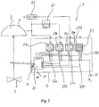
- Figur 1
- eine schematische Darstellung eines erfindungsgemäßen pneumatischen Antriebssystems;
- Figur 2
- eine schematische Darstellung einer weiteren bevorzugten Ausführung des pneumatischen Antriebssystems gemäß der Erfindung;
- Figur 3
- eine schematische Darstellung einer weiteren Ausführung eines erfindungsgemäßen pneumatischen Antriebssystems.
- In
Figur 1 ist ein pneumatisch betriebenes, erfindungsgemäßes Antriebssystem im Allgemeinen mit der Bezugsziffer 1 versehen. Mittels des Antriebssystems ist ein Stellventil 5 betätigt, welches zur Regelung einer Prozessfluidströmung einer nicht dargestellten prozesstechnischen Anlage, wie einer petrochemischen Anlage, einer Lebensmittel verarbeitenden Anlage, wie einer Bauerei, oder dergleichen eingesetzt wird. Das Stellventil kann auch ein Pumpgrenzventil eines Kompressors oder ein Sicherheitsschnellabschaltventil sein. Das pneumatische Antriebssystem 1 umfasst einen pneumatischen Stellantrieb 4 mit einer Arbeitskammer 3, der auf das Stellventil 5 zum Regeln der Prozessfluidströmung der nicht dargestellten prozesstechnischen Anlage einwirkt, und eine Strom-Druckwandlung 7, die als Stellungsregler ausgebildet ist und an die ein pneumatisches Leitungssystem 11 zur Verbindung mit der Arbeitskammer 3 des Stellantriebs 4 anschließt. - Das Stellventil 5 ist mit dem pneumatischen Stellantrieb 4 über eine Spindel oder Welle 13 verbunden. Ein Positionssensor 15, der teilweise innerhalb eines Gehäuses 17 der Strom-Druckwandlung 7 angeordnet ist, greift die Momentanstellung X des Stellventils 5 ab. Der Positionssensor 15 gibt ein Positionssignal an einen Mikroprozessor 21 ab, der darstellungsgemäß in einem Innenraum des Gehäuses 17 untergebracht ist und über einen Feldeingang 18 ein Soll-Stell-Signal w von einer nicht näher dargestellten Leitstelle der prozesstechnischen Anlage empfängt. Neben dem elektrischen Feldeingang 18 weist die Strom-Druckwandlung einen pneumatischen Feldeingang 33 auf, der an eine pneumatische Versorgungsquelle 31 angeschlossen ist, sowie vier Ausgänge A1-4, welche die pneumatischen oder elektrischen Ausgangssignale S1-4 der Steck- oder Einschubplätze 23a, 23b, 23c, 23d extern der Strom-Druckwandlung 7 bereitstellen.
- Die Strom-Druckwandlung 7 oder der Stellungsregler hat vier, im Wesentlichen gleich aufgebaute, von außen frei zugängliche Steck- oder Einschubplätze 23a, 23b, 23c, 23d, welche optional mit vier einzelnen Elektronikkomponenten unterschiedlichster Bauart belegbar sind. Die Elektronikkomponente kann ein I/P-Wandler, ein Datenspeicher, ein pneumatisch betriebener Stromgenerator, der Mikroprozessor 21 und/oder ein Elektronikschalter sein, wobei auch Elektronikkomponenten gleicher Bauart unterschiedlicher Funktionsweise oder Leistungsparameter in den Steckplätzen eingesetzt werden können. Die Steckplätze 23a bis 23d sind derart modular angepasst, dass sie je nachdem, welche vorbestimmte elektronische Komponente eingesetzt wird, die Funktion der Elektronikkomponente durch Herstellung von Kommunikationsleitungen zu den jeweils anderen Bauelementen gewährleisten.
- Die Steckplätze 23a bis 23d haben eine pneumatische Eingangsschnittstelle 25a bis 25d, die mit einer Versorgungsleitung 27 verbunden ist, sowie elektrische Eingangsschnittstellen 35a bis 35d, die mit dem Mikroprozessor 21 verbunden sind, und Ausgangsschnittstellen 33a bis 33d. Jeder Steckplatz 23a bis 23d hat außerdem eine Ausgangsschnittstelle 37a bis 37d, über die Ausgangssignale entweder elektrischer Natur (nicht in
Figur 1 dargestellt) oder pneumatischer Natur S1-4 an dem jeweiligen Ausgang A1 bis A4 abgegeben werden kann. Bei der inFigur 1 dargestellten Ausführung sind in den Steckplätzen 23a bis 23d vier I/p-Wandler vorgesehen, die über die Ausgänge A1-4 pneumatische Stelldrucksignale S1-4 abgegeben. - Die pneumatische Ausgänge A1-4 münden in einer gemeinsamen Leitung 41 zur Ansteuerung der Arbeitskammer 3. Wenngleich nicht dargestellt, können ein oder zwei Ausgänge auch über separate Leitungen direkt mit einer oder mehreren Arbeitskammern eines Stellantriebs verbunden sein.
- Je nachdem welche Luftleistung dem elektropneumatischen Feldgerät 7 zugeordnet sein soll, können die Steckplätze 23a bis 23d auch mit vier unterschiedlichsten I/P-Wandlern belegt sein. Wird ein Steckplatz 23a bis 23d mit einem I/P-Wandler belegt, so erkennt der Mikroprozessor 21 die Belegung über beispielsweise eine geeignete, nicht dargestellte Sensorik und/oder über die jeweilige die elektrische Eingangsschnittstelle 35a bis 35d mit dem elektrischen Mikroprozessorausgang O1-4 verbindenden Leitung.
- Durch vier separate in die Steckplätze 23a bis 23d eingesetzte I/p-Wandler lässt sich eine Stellantriebsbeschaltung mit vier entkoppelten Stelldrucksignalen erreichen, die bei gemeinsamer Ansteuerung und gleicher jeweiliger Luftleistung des I/p-Wandlers eine vierfach zugeführte Luftleitung realisieren. Somit lässt sich das Stellventil auch bei großen Lasten vergleichsweise schnell die gewünschte Position bringen, wobei zur Feinregelung nach Bedarf ein-, zwei- oder drei Stelldrucksignale abgeschaltet werden können, um eventuelles Überschwingen beim Anfahren der gewünschten Stellposition zu vermeiden.
- Sollten mehrere Steckplätze 23a bis 23d mit unterschiedlichen I/P-Wandlern belegt sein, so kann der Mikroprozessor 21 einen dieser zum Betrieb des Stellantriebs 3 auswählen oder mehrere simultan ansteuern. Wählt der Mikroprozessor 21 beispielweise den in dem Steckplatz 23c angeordneten I/P-Wandler mit einer bestimmten Luftleistung aus, so gibt der Mikroprozessor 21 über seinen Ausgang I3 ein entsprechendes elektrisches Regelsignal an den in dem Steckplatz 23c angeordneten I/P-Wandler ab, der ein entsprechendes Luftdrucksignal S3 über die pneumatische Ausgangsschnittstelle 37c an den pneumatischen Stellantrieb 3 abgibt, wobei die restlichen I/P-Wandler in den Steckplätzen 23a, 23b, 23d durch den Mikroprozessor 21 deaktiviert oder zumindest unangesprochen bleiben.
- Anstatt mehrerer I/P-Wandler können in dem Steckplatz 23a bis 23d auch andere Komponenten der Strom-Druckwandlung eingesetzt sein, wie der Mikroprozessor 21, ein Datenspeicher, ein Funkmodul oder eine elektrische Schaltung zur Kommunikation mit externen elektrischen Baukomponenten.
- In
Figur 2 sind drei der modularen Steckplätzen 23a bis 23d der Strom-Druckwandlung 7 mit einem I/P-Wandler 55a, 55b, 55c belegt sowie einer der modularen Steckplätze 23d mit einem funktionslosen Leermodul 57. - Die I/p-Wandler 55a, 55b, 55c erzeugen drei pneumatische Stelldrucksignale S1-3. Das Stelldrucksignal S1 wird direkt zur Zuführleitung des Stellantriebs 3 geführt. Das Stelldrucksignal S2 wird über einen Volumenverstärker 61 verstärkt und als Signal mit größerem Volumenstrom mit der Zuführleitung des Stellantriebs 3 gekoppelt. Das dritte Stelldrucksignal S3 dient im Wesentlichen der Schaltung eines Schnellentlüfters 63 für den Stellantrieb 3, der bei einem vorbestimmten Stelldrucksignalabfall am Ausgang A3 zum Entlüften der pneumatischen Leitungen zum Stellantrieb 3 führt.
- In
Figur 3 ist die Stromdruckwandlung 7 derart ausgebildet, dass in dem Steckplatz 23a eine elektrische Ausgangsstufe 65 zur Ansteuerung eines Magnetventils 67 angeordnet ist. Des Weiteren sind in den Steckplätzen 23b und 23c zwei I/p-Wandler 55b, 55c eingesetzt. Die Ausgänge A2-3 der I/p-Wandler 55b, 55c sind in einer gemeinsamen Zuleitung zum Stellantrieb 3 gekoppelt. Im vierten Steckplatz 23d ist beispielhaft ein Datenspeicher M vorgesehen. Das Magnetventil 67 kann so angesteuert werden, dass die Stelldrucksignale S2-3 der I/p-Wandler zum Stellantrieb geleitet werden können oder zur Entlüftung des Stellantriebs. Das bei durchgeschaltetem Magnetventil 67 zum Stellantrieb geführte Stelldrucksignal kann je nach Ansteuerung der I/p-Wandler lediglich eines der Stelldrucksignale S2 und S3 umfassen oder eine Kombination beider Stelldrucksignale S2 und S3 sein. In der Regel ist eines der Stelldrucksignale als Hochdrucksignal und eines der Stelldrucksignale als Niederdruckstellsignal ausgeführt, um eine größere Variabilität bei der Ansteuerung des Stellantriebs zu erreichen. - Abhängig von den Leistungsparametern und der Anzahl der eingesetzten I/p-Wandlermodule können gleiche Stelldrucksignale, oder ein oder mehrere Hochdruck- und/oder Niederdruckstellsignale kombiniert oder als Paare von je einem Hochdruck- und Niederdruckstellsignal einer oder mehreren Arbeitskammern zugeführt werden.
- Mit den Anordnungen gemäß den
Figuren 1 bis 3 kann beispielsweise eine schnelle Druckregelung in der Antriebskammer des Stellantriebs 3 erfolgen. Dazu kann optional in einem der Steckplätze 23a bis 23d eine Druckerfassungskomponente vorgesehen sein. Bei großer Drucksollwertänderung lässt sich eine schnelle Druckanpassung beispielsweise dadurch erreichen, dass mehrere Stelldrucksignale dem Stellantrieb zugeführt werden, z.B. alle Stelldrucksignale S1-4 gemäßFigur 1 oder das Signal S2, großer Volumenstrom, mit dem Signal S1 gemäßFigur 2 oder beide Stelldrucksignale S2-3 gemäßFigur 3 . - Um eine exakte Druckregelung zu ermöglichen, kann eines der Drucksignale, bei ungleichen Drucksignalen dasjenige größeren Volumenstroms, nur für eine kurze Zeitspanne zugeschaltet werden und die Feinregelung im Wesentlichen über das weitere Stelldrucksignal erfolgen. Bei kleinen Drucksollwertänderungen kann auch ausschließlich eine Niederdruckstellsignal oder ein Signal kleinen Volumenstroms eingesetzt werden. Bei mehr als zwei zusammen geschalteten Stelldrucksignalen, können andere Signalkombinationen vorteilhaft sein, z.B. schnelle Druckänderung mit drei Signalen und Feinregelung mit zwei Signalen oder einem Signal.
- In gleicher Weise kann eine schnelle Regelung der Ventilposition des Stellventils 5 beispielsweise gemäß
Figur 2 erreicht werden, wobei zur schnellen Überwindung des Ventilwegs ein großer Volumenstrom durch Kombination des verstärkten Stelldrucksignals S2 mit dem Stelldrucksignal S1 erreicht wird, und die Feinregelung unter Reduktion des Volumenstroms durch das unverstärkte Signal S1 erfolgt. - Des Weiteren kann beispielsweise gemäß
Figur 3 eine simultane Ansteuerung mit zwei Stelldrucksignalen S2-3 helfen, bei einem Ventil die Haftreibung zu überwinden und damit die durch das Haften resultierende Verzugszeit zu vermindern, die üblicherweise die Regelung erschwert. Eines der Stelldrucksignale wird dabei nach Überwindung der Haftreibung durch Deaktivierung des I/p-Wandlers abgeschaltet. Der Zeitpunkt der Überwindung der Haftreibung kann durch einen Referenzversuch bestimmt und im Mikroprozessor abgelegt sein oder durch geeignete Messtechnik, die ebenfalls als Modul in einem Einsteckplatz vorgesehen sein kann, festgestellt werden. Die letztendliche Feinregelung der Ventilposition erfolgt auf Basis eines Stelldrucksignals, nämlich des Niederdruckstellsignals. - Die Regelzuverlässigkeit mit der Anordnung gemäß dem Ausführungsbeispiel der
Figur 3 dadurch verbessert werden, dass bei einer schnellen Positionsregelung unter Verwendung beider Stelldrucksignale S2-3 im Fall einer Schwinganregung durch das Prozessmedium eines der Stelldrucksignale abgeschaltet wird und die Regelung ausschließlich auf Basis nur eines Signals, in der Regel des Niederdruckstellsignals, erfolgt, bis die Schwingneigung abgenommen hat. - Die in der vorstehenden Beschreibung, den Figuren und den Ansprüchen offenbarten Merkmale können sowohl einzeln als auch in beliebiger Kombination für die Realisierung der Erfindung in den verschiedenen Ausgestaltungen von Bedeutung sein.
-
- 1
- Pneumatisches Antriebssystem
- 3
- Arbeitskammer
- 4
- pneumatischer Stellantrieb
- 5
- Stellventil
- 7
- Strom-Druckwandlung
- 11
- pneumatische Leitungssystem
- 13
- Spindel
- 15
- Positionssensor
- 17
- Gehäuse
- 18,33
- Feldeingang
- 21
- Mikroprozessor
- 23a,b,c,d
- Steck- und Einschubplätze
- 25a,b,c,d
- pneumatische Eingangsschnittstelle
- 33a,b,c,d
- elektrische Ausgangschnittstelle
- 35a,b,c,d
- elektrische Eingangschnittstelle
- 37a,b,c,d
- Ausgangsschnittstelle
- 55a,b,c
- I/p-Wandler
- 27
- Versorgungsleitung
- 31
- Versorgungsquelle
- 41
- Leitungen
- 43
- Andockmechanismus
- 45
- Elektronikkomponente
- 47
- elektrischer Eingang
- 49
- elektrischer Ausgang
- 61
- Volumenstromverstärker
- 63
- Schnellentlüfter
- 65
- Ausgangsstufe
- 65
- Magnetventil
- A1-4
- Ausgänge
- I1-4
- Mikroprozessoreingang
- M
- Datenspeicher
- O1-4
- Mikroprozessorausgang
- PZ
- Versorgungsdruck
- S1-4
- Ausgangssignal
- W
- Soll-Stell-Signal
- X
- Momentanstellung
Claims (13)
- Pneumatisches Antriebssystem (1) zum Betätigen eines Stellventils (5), insbesondere eines Regelungsstellventils oder eines Sicherheitsventils, einer prozesstechnischen Anlage, umfassend eine pneumatische Arbeitskammer (3) und eine mit der Arbeitskammer (3) gekoppelte Strom-Druckwandlung (7) zum Beaufschlagen der Arbeitskammer (3) mit einem Pneumatikdruck, durch den das Stellventil (5) verfahren werden kann,
wobei die Strom-Druckwandlung (7) wenigstens einen elektrischen Eingang (w) zum Empfangen eines elektrischen Stellsignals aufweistwobei die Strom-Druckwandlung (7) wenigstens zwei pneumatische Stellsignale (S1, S2, S3, S4) erzeugt, mit denen die eine Arbeitskammer (3) beaufschlagt ist, dadurch gekennzeichnet, dass die Strom-Druckwandlung wenigstens zwei pneumatisch getrennte Pneumatikausgänge (A1, A2, A3, A4) aufweist, die mit der einen Arbeitskammer (3) verbunden sind und an denen die wenigstens zwei Stellsignale getrennt voneinander die Strom-Druckwandlung verlassen. - Antriebssystem nach Anspruch 1, dadurch gekennzeichnet, dass die Strom-Druckwandlung (7) die wenigstens zwei Stellsignale (S1, S2, S3, S4) unabhängig von einander erzeugt und/oder die wenigstens zwei Stellsignale (S1, S2, S3, S4) unabhängig voneinander der einen Arbeitskammer (3) zuführt und/oder die wenigstens zwei Stelldrucksignale gemäß einer vorgegebenen oder geregelten Taktung insbesondere gleichzeitig, nacheinander aufsummierend oder nacheinander abwechselnd der Arbeitskammer (3) zuführt.
- Antriebssystem nach Anspruch 1 oder 2, dadurch gekennzeichnet, dass Luftdurchflüsse der wenigstens zwei Stellsignale (S1, S2, S3, S4) voreingestellt sind und/oder von den wenigstens zwei Stellsignalen eines einen geringen Luftdurchfluss und ein anderes einen großen Luftdurchfluss aufweist, wobei insbesondere der große Luftdurchfluss wenigstens doppelt so groß wie der geringe Luftdurchfluss ist, wobei insbesondere die Strom-Druckwandlung (7) derart gesteuert ist, dass für eine Schnellverlagerung des Stellventils (5) zuerst das Stellsignal mit großem Luftdurchfluss oder beide Stellsignale und anschließend lediglich das Stellsignal mit geringem Luftdurchfluss der Arbeitskammer (3) zugeführt ist.
- Antriebssystem nach einem der vorstehenden Ansprüche, dadurch gekennzeichnet, dass die Strom-Druckwandlung (7) eine Regelungselektronik, wie einen Mikrorechner (21), aufweist, die anhand eines empfangenen Sollstellwerts (w) und/oder Iststellwerts (X) die Erzeugung und/oder Zuführung der wenigstens zwei Stellsignale (S1, S2, S3, S4) regelt, wobei insbesondere die Regelungselektronik mit wenigstens zwei I/p-Wandlern der Strom-Druckwandlung (7) regelungsgemäß gekoppelt ist, die unabhängig voneinander arbeitend das jeweilige Stellsignal (S1, S2, S3, S4) erzeugen insbesondere nach Empfang eines für den jeweiligen I/p-Wandler spezifizierten elektrischen Stellsignals der Regelungselektronik, wobei insbesondere die wenigstens zwei I/p-Wandler an eine Druckluftquelle vorzugsweise konstanten Versorgungsdrucks angeschlossen sind.
- Antriebssystem nach Anspruch 4, dadurch gekennzeichnet, dass die Regelungselektronik einen Taktgeber aufweist, der die Beaufschlagung der Arbeitskammer (3) mit wenigstens zwei Stellsignalen (S1, S2, S3, S4) derart zeitlich taktet, dass die Stellsignale (S1, S2, S3, S4) gleichzeitig oder sukzessive sich überlagernd oder sich ausschließend in einem regelungsgemäßen Zeitabstand der Arbeitskammer (3) zugeführt werden.
- Antriebssystem nach einem der vorstehenden Ansprüche, , dadurch gekennzeichnet, dass die wenigstens zwei Pneumatikausgänge (A1, A2, A3, A4) durch den Einzelausgang (37a, 37b, 37c, 37d) eines I/p-Wandlers gebildet sind.
- Antriebssystem nach einem der vorstehenden Ansprüche, dadurch gekennzeichnet, dass von der Strom-Druckwandlung (7) ein Leitungsnetz (11) mit Parallelleitungen anschließt, die jeweils ein Stellsignal (S1, S2, S3, S4) führen, wobei insbesondere an den wenigstens zwei pneumatisch getrennten Pneumatikausgängen jeweils eine separate Parallelleitung angeschlossen ist, die insbesondere jede für sich in die Arbeitskammer (3) insbesondere jeweils an einer eigenen Öffnung mündet, die in einem die Arbeitskammer begrenzenden Antriebsgehäuse ausgebildet ist, oder die Parallelleitungen in eine Hauptzuführleitung mündet, die in die Arbeitskammer (3) führt.
- Verfahren zum Betreiben eines pneumatischen Antriebssystems (1) zur Betätigung eines Stellventils (5), insbesondere eines Regelungsstellventils oder eines Sicherheitsventils, einer prozesstechnischen Anlage, wobei eine pneumatische Arbeitskammer (3) mit Pneumatikdruck beaufschlagt wird, um das Stellventil (5) in eine Sollstellung zu verfahren, wobei anhand elektropneumatischer Umwandlung zwei oder mehrere, pneumatische Stellsignale (S1, S2, S3, S4) der einen Arbeitskammer (3) zugeführt werden, dadurch gekennzeichnet, dass die wenigstens zwei Stellsignale die Strom-Druckwandlung getrennt voneinander an wenigstens zwei pneumatisch getrennten Pneumatikausgängen (A1, A2, A3, A4) der Strom-Druckwandlung verlassen, die mit der einen Arbeitskammer (3) verbunden sind.
- Verfahren nach Anspruch 8, dadurch gekennzeichnet, dass jedes Stellsignal (S1, S2, S3, S4) durch eine individuelle Strom-Druckwandlungsprozedur erzeugt wird und/oder die wenigstens zwei Stellsignale sich überlagernd oder sich ausschließend, gleichzeitig oder nacheinander der einen Arbeitskammer (3) zugeführt werden.
- Verfahren nach Anspruch 8 oder 9, dadurch gekennzeichnet, dass Luftdurchflüsse der wenigstens zwei Stellsignale (S1, S2, S3, S4) voreingestellt werden und/oder von den wenigstens zwei Stellsignalen eines mit einem geringen Luftdurchfluss und ein anderes mit hohem Luftdurchfluss versehen werden, wobei insbesondere der hohe Lustdurchfluss wenigstens doppelt so groß wie der geringe Luftdurchfluss ist, wobei insbesondere für eine Schnellverlagerung des Stellventils (5) zuerst das Stellsignal mit hohem Luftdurchfluss oder beide Stellsignale und anschließend lediglich das Stellsignal mit geringem Luftdurchfluss der Arbeitskammer (3) zugeführt werden.
- Verfahren nach einem der Ansprüche 8 bis 10, dadurch gekennzeichnet, dass zum Regeln der Stellung des Stellventils (5) die wenigstens zwei Stellsignale (S1, S2, S3, S4) mit unterschiedlich großen Luftdurchflüssen versehen werden, wobei die wenigstens zwei pneumatischen Stellsignale gleichzeitig der Arbeitskammer (3) zugeführt werden und im Falle, dass eine zulässige Schwingungsamplitudengrenze und/oder -Frequenzgrenze an dem Stellventil überschritten wird, das Stellsignal mit hohem Luftdurchfluss unter Aufrechterhaltung des Stellsignals mit geringem Luftdurchfluss abgeschaltet wird und gegebenenfalls nach Unterschreitung der zulässigen Grenze das Stellsignal mit hohem Luftdurchfluss wieder zugeschaltet wird.
- Verfahren nach einem der Ansprüche 8 bis 11, dadurch gekennzeichnet, dass die wenigstens zwei Stellsignale (S1, S2, S3, S4) mit unterschiedlich großen Druckbeträgen oder Luftdurchflüssen versehen werden, wobei zum Öffnen oder Schließen eines Sicherheitsventils insbesondere nur das Hochdruckstellsignal oder Stellsignal mit hohem Luftdurchfluss eingeschaltet wird und/oder zum Durchführen eines Partial-Stroke-Tests nur das Niederdruckstellsignal oder das Stellsignal mit geringem Luftdurchfluss eingeschaltet wird.
- Verfahren nach einem der Ansprüche 8 bis 12, dadurch gekennzeichnet, dass zum Verlagern des Stellventils (5), insbesondere eines Pumpgrenzregelventils, zwei Stellsignale insbesondere mit unterschiedlich großen Druckbeträgen gleichzeitig der einen Arbeitskammer (3) während eines vorzugsweise vorab festgelegten Impulszeitraums, insbesondere von weniger als 1 Sekunde, oder solange zugeführt wird, bis das Stellventil anspricht, und anschließend eines der Stellsignale, insbesondere das Hochdruckstellsignal, abgeschaltet wird und insbesondere nur noch ein Niederdruckstellsignal wirkt, wobei insbesondere die Länge des Impulszeitraums beispielsweise aus Erfahrungsreferenzen eingestellt wird.
Applications Claiming Priority (1)
| Application Number | Priority Date | Filing Date | Title |
|---|---|---|---|
| DE102012021388.3A DE102012021388B4 (de) | 2012-10-31 | 2012-10-31 | Pneumatisches Antriebssystem und Verfahren zum Betreiben des pneumatischen Antriebssystems |
Publications (3)
| Publication Number | Publication Date |
|---|---|
| EP2728202A2 EP2728202A2 (de) | 2014-05-07 |
| EP2728202A3 EP2728202A3 (de) | 2017-04-05 |
| EP2728202B1 true EP2728202B1 (de) | 2019-10-23 |
Family
ID=49322130
Family Applications (1)
| Application Number | Title | Priority Date | Filing Date |
|---|---|---|---|
| EP13004695.6A Active EP2728202B1 (de) | 2012-10-31 | 2013-09-27 | Pneumatisches Antriebssystem und Verfahren zum Betreiben des pneumatischen Antriebssystems |
Country Status (3)
| Country | Link |
|---|---|
| US (1) | US9500293B2 (de) |
| EP (1) | EP2728202B1 (de) |
| DE (1) | DE102012021388B4 (de) |
Families Citing this family (14)
| Publication number | Priority date | Publication date | Assignee | Title |
|---|---|---|---|---|
| EP2829379A1 (de) * | 2013-07-22 | 2015-01-28 | Eugen Seitz AG | Ventilanordnung |
| DE102014211258A1 (de) * | 2014-06-12 | 2015-12-17 | Materialforschungs- und -prüfanstalt an der Bauhaus-Universität Weimar | Vorrichtung zur Erzeugung definierter Druckverläufe |
| DE102014013098B3 (de) | 2014-09-03 | 2015-12-03 | Samson Aktiengesellschaft | Stellungsregler für ein pneumatisches Stellgerät |
| DE102014019575B4 (de) | 2014-12-23 | 2017-03-16 | Samson Aktiengesellschaft | Fluidbetriebener Antrieb einer prozesstechnischen Anlage sowie Verfahren zum Betreiben eines fluidbetriebenen Antriebs einer prozesstechnischen Anlage |
| DE102015007147A1 (de) | 2015-06-03 | 2016-12-08 | Samson Aktiengesellschaft | Elektro-pneumatischer Aktor |
| JP2017194122A (ja) * | 2016-04-21 | 2017-10-26 | アズビル株式会社 | ポジショナおよびバルブ制御システム |
| DE202016106017U1 (de) * | 2016-10-26 | 2018-01-28 | Samson Aktiengesellschaft | Elektropneumatischer Stellungsregler und Feldgerät mit einem elektropneumatischen Stellungsregler |
| US10634003B2 (en) | 2017-01-20 | 2020-04-28 | Emerson Process Management Regulator Technologies, Inc. | Methods and apparatus to control the actuation of regulators including a loading chamber |
| EP3252547B1 (de) * | 2017-05-02 | 2019-07-03 | Primetals Technologies Austria GmbH | Verfahren zum steuern einer bewegung eines beweglich gelagerten körpers eines mechanischen systems |
| DE102017207414A1 (de) * | 2017-05-03 | 2018-11-08 | Festo Ag & Co. Kg | Pneumatische Steuervorrichtung und damit ausgestattete Prozesssteuervorrichtung |
| US10724555B2 (en) | 2017-07-28 | 2020-07-28 | Dresser, Llc | Generating two pneumatic signals to operate an actuator on a valve assembly |
| US10746314B2 (en) * | 2018-09-14 | 2020-08-18 | Fisher Controls International Llc | Positioner apparatus for use with fluid valves |
| EP4083441A1 (de) * | 2021-04-30 | 2022-11-02 | ABB Schweiz AG | Stellungsreglerantrieb zur steuerung eines ventilstellungsreglers mit pneumatischem ausgang |
| CN118881607B (zh) * | 2024-07-17 | 2025-11-25 | 中国煤炭科工集团太原研究院有限公司 | 一种自适应钻孔无级调速系统 |
Family Cites Families (15)
| Publication number | Priority date | Publication date | Assignee | Title |
|---|---|---|---|---|
| US3038449A (en) * | 1959-06-03 | 1962-06-12 | Gen Dynamics Corp | Hydraulic control system |
| US3813990A (en) * | 1972-04-12 | 1974-06-04 | Gen Electric | Servo system including flow voting redundant failure correcting hydraulic actuator |
| FR2506904A1 (fr) * | 1981-05-29 | 1982-12-03 | Applic Catalytiques Ste Ly | Procede de regulation d'une installation de chauffage et dispositif pour sa mise en oeuvre |
| EP0126291B1 (de) * | 1983-05-19 | 1988-07-27 | GebràDer Sulzer Aktiengesellschaft | Druckmediumbetätigtes Ventil |
| US4763560A (en) * | 1984-05-25 | 1988-08-16 | Tokyo Precision Instruments Co., Ltd. | Method and apparatus of controlling and positioning fluid actuator |
| US4723474A (en) * | 1986-02-05 | 1988-02-09 | Smith International, Inc. | Pneumatic stepping actuator positioner |
| US4815694A (en) * | 1987-03-31 | 1989-03-28 | The Bran Ferren Corporation | High speed, high volume gas pulse generator |
| DE19540441A1 (de) * | 1995-10-27 | 1997-04-30 | Schubert & Salzer Control Syst | Mikroprozessorgesteuerter Stellungsregler |
| DE60205049T2 (de) * | 2001-03-07 | 2006-04-13 | Max Co. Ltd. | Druckluftversorgungsgerät mit einem Verdichter |
| US8515692B2 (en) * | 2006-10-25 | 2013-08-20 | Panasonic Corporation | Flow rate measuring apparatus and program thereof |
| DE102008007651B3 (de) | 2008-02-06 | 2009-09-24 | Samson Aktiengesellschaft | Stellungsregler für doppeltwirkenden, pneumatischen Stellantrieb, doppeltwirkender, pneumatischer Stellantrieb und Verfahren zum Betreiben des doppeltwirkenden, pneumatischen Stellantriebs |
| DE102010007152B4 (de) * | 2010-02-05 | 2017-03-30 | Hoerbiger Automatisierungstechnik Holding Gmbh | Fluidbetätigter Stellantrieb an einer Armatur |
| US8517335B2 (en) * | 2010-05-21 | 2013-08-27 | Sti Srl | Fail-freeze device for positioner |
| DE102010035747B4 (de) * | 2010-08-28 | 2013-05-29 | Festo Ag & Co. Kg | Ventileinheit |
| DE102010054878A1 (de) * | 2010-12-17 | 2012-06-21 | Samson Aktiengesellschaft | Elektropneumatisches Feldgerät |
-
2012
- 2012-10-31 DE DE102012021388.3A patent/DE102012021388B4/de active Active
-
2013
- 2013-09-27 EP EP13004695.6A patent/EP2728202B1/de active Active
- 2013-10-28 US US14/064,416 patent/US9500293B2/en active Active
Non-Patent Citations (1)
| Title |
|---|
| None * |
Also Published As
| Publication number | Publication date |
|---|---|
| EP2728202A3 (de) | 2017-04-05 |
| EP2728202A2 (de) | 2014-05-07 |
| DE102012021388A1 (de) | 2014-04-30 |
| US20140117263A1 (en) | 2014-05-01 |
| US9500293B2 (en) | 2016-11-22 |
| DE102012021388B4 (de) | 2022-02-03 |
Similar Documents
| Publication | Publication Date | Title |
|---|---|---|
| DE102012021388B4 (de) | Pneumatisches Antriebssystem und Verfahren zum Betreiben des pneumatischen Antriebssystems | |
| DE102008007651B3 (de) | Stellungsregler für doppeltwirkenden, pneumatischen Stellantrieb, doppeltwirkender, pneumatischer Stellantrieb und Verfahren zum Betreiben des doppeltwirkenden, pneumatischen Stellantriebs | |
| EP2182221B1 (de) | Elektro-pneumatisches System zum Steuern eines doppelt wirkenden pneumatischen Stellantriebs | |
| DE102008038723B3 (de) | Verfahren und Einrichtung zur Ansteuerung eines elektropneumatischen Ventils eines druckmittelbetätigten Stellungsreglers | |
| EP1502010B1 (de) | Dampfturbine | |
| EP2466175A1 (de) | Elektropneumatisches Feldgerät | |
| EP2161640A2 (de) | Verfahren zur Überwachung der Funktionsfähigkeit eines Stellgeräts mit pneumatischem Antrieb | |
| EP3339992A1 (de) | Regelungs- und/oder steuerungsverfahren für ein elektropneumatisches feldgerät | |
| DE10222890B4 (de) | Elektrische Einrichtung für die Ansteuerung eines Mehrwegeventils mit einer Verschleißzustandserkennung | |
| EP1857361B1 (de) | Klimaanlage mit einer redundanten zuführung von versorgungsluft | |
| EP3318769B1 (de) | Elektropneumatischer stellungsregler und feldgerät mit einem eletropneumatischen stellungsregler | |
| EP2706424B1 (de) | Vorrichtung zur Druck- und/oder Massenstromregelung für einen Raumfahrtantrieb | |
| EP3592991B1 (de) | Verfahren zum ansteuern eines hydraulischen stellantriebes, steuereinrichtung und stellantriebsteuerung | |
| WO2006072377A1 (de) | Redundante elektrohydraulische ventilanordnung | |
| DE602004007138T2 (de) | Elektromagnetisch betriebene Ventilvorrichtung die mit variabler Funktion schaltet und luftbetriebene Ventilaktuatoren aufweist und ein Testverfahren dafür | |
| EP4636259A1 (de) | Ventilanordnung | |
| EP2850234B1 (de) | Luftduesenwebmaschine mit einer vorrichtung zur druckluftversorgung | |
| DE102020205446B4 (de) | Arbeitseinrichtung zur Durchführung eines Arbeitsvorgangs und Verfahren zum Betreiben einer Arbeitseinrichtung | |
| DE102011116819B4 (de) | Verfahren zum Ansteuern eines elektrisch betreibbaren Stellmittels für ein Fluidsteuerventil und Ventileinrichtung | |
| EP2502598A1 (de) | Dentalstrahlgerätevorrichtung mit einem Druckluftversorgungssystem | |
| DE102019213908A1 (de) | Fluidisches System und Verfahren | |
| EP4279738B1 (de) | Pneumatische betätigungsvorrichtung und einheit | |
| DE102014202558A1 (de) | Digitalhydraulischer druckregler und überprüfungsverfahren eines digitalhydraulischen druckreglers | |
| DE2413104B2 (de) | Sicherheitssteuereinrichtung | |
| DE102010063121A1 (de) | Vorrichtung zum Betreiben eines CVT-Getriebes |
Legal Events
| Date | Code | Title | Description |
|---|---|---|---|
| PUAI | Public reference made under article 153(3) epc to a published international application that has entered the european phase |
Free format text: ORIGINAL CODE: 0009012 |
|
| 17P | Request for examination filed |
Effective date: 20130927 |
|
| AK | Designated contracting states |
Kind code of ref document: A2 Designated state(s): AL AT BE BG CH CY CZ DE DK EE ES FI FR GB GR HR HU IE IS IT LI LT LU LV MC MK MT NL NO PL PT RO RS SE SI SK SM TR |
|
| AX | Request for extension of the european patent |
Extension state: BA ME |
|
| PUAL | Search report despatched |
Free format text: ORIGINAL CODE: 0009013 |
|
| AK | Designated contracting states |
Kind code of ref document: A3 Designated state(s): AL AT BE BG CH CY CZ DE DK EE ES FI FR GB GR HR HU IE IS IT LI LT LU LV MC MK MT NL NO PL PT RO RS SE SI SK SM TR |
|
| AX | Request for extension of the european patent |
Extension state: BA ME |
|
| RIC1 | Information provided on ipc code assigned before grant |
Ipc: G05B 19/44 20060101ALI20170224BHEP Ipc: F15B 5/00 20060101AFI20170224BHEP Ipc: G05D 7/06 20060101ALI20170224BHEP Ipc: G05D 7/00 20060101ALI20170224BHEP |
|
| STAA | Information on the status of an ep patent application or granted ep patent |
Free format text: STATUS: REQUEST FOR EXAMINATION WAS MADE |
|
| 17P | Request for examination filed |
Effective date: 20170412 |
|
| RBV | Designated contracting states (corrected) |
Designated state(s): AL AT BE BG CH CY CZ DE DK EE ES FI FR GB GR HR HU IE IS IT LI LT LU LV MC MK MT NL NO PL PT RO RS SE SI SK SM TR |
|
| GRAP | Despatch of communication of intention to grant a patent |
Free format text: ORIGINAL CODE: EPIDOSNIGR1 |
|
| STAA | Information on the status of an ep patent application or granted ep patent |
Free format text: STATUS: GRANT OF PATENT IS INTENDED |
|
| INTG | Intention to grant announced |
Effective date: 20190513 |
|
| GRAS | Grant fee paid |
Free format text: ORIGINAL CODE: EPIDOSNIGR3 |
|
| GRAA | (expected) grant |
Free format text: ORIGINAL CODE: 0009210 |
|
| STAA | Information on the status of an ep patent application or granted ep patent |
Free format text: STATUS: THE PATENT HAS BEEN GRANTED |
|
| AK | Designated contracting states |
Kind code of ref document: B1 Designated state(s): AL AT BE BG CH CY CZ DE DK EE ES FI FR GB GR HR HU IE IS IT LI LT LU LV MC MK MT NL NO PL PT RO RS SE SI SK SM TR |
|
| REG | Reference to a national code |
Ref country code: GB Ref legal event code: FG4D Free format text: NOT ENGLISH |
|
| REG | Reference to a national code |
Ref country code: CH Ref legal event code: EP |
|
| REG | Reference to a national code |
Ref country code: IE Ref legal event code: FG4D Free format text: LANGUAGE OF EP DOCUMENT: GERMAN |
|
| REG | Reference to a national code |
Ref country code: DE Ref legal event code: R096 Ref document number: 502013013787 Country of ref document: DE |
|
| REG | Reference to a national code |
Ref country code: AT Ref legal event code: REF Ref document number: 1193954 Country of ref document: AT Kind code of ref document: T Effective date: 20191115 |
|
| REG | Reference to a national code |
Ref country code: NL Ref legal event code: MP Effective date: 20191023 |
|
| REG | Reference to a national code |
Ref country code: LT Ref legal event code: MG4D |
|
| PG25 | Lapsed in a contracting state [announced via postgrant information from national office to epo] |
Ref country code: SE Free format text: LAPSE BECAUSE OF FAILURE TO SUBMIT A TRANSLATION OF THE DESCRIPTION OR TO PAY THE FEE WITHIN THE PRESCRIBED TIME-LIMIT Effective date: 20191023 Ref country code: NL Free format text: LAPSE BECAUSE OF FAILURE TO SUBMIT A TRANSLATION OF THE DESCRIPTION OR TO PAY THE FEE WITHIN THE PRESCRIBED TIME-LIMIT Effective date: 20191023 Ref country code: PL Free format text: LAPSE BECAUSE OF FAILURE TO SUBMIT A TRANSLATION OF THE DESCRIPTION OR TO PAY THE FEE WITHIN THE PRESCRIBED TIME-LIMIT Effective date: 20191023 Ref country code: LT Free format text: LAPSE BECAUSE OF FAILURE TO SUBMIT A TRANSLATION OF THE DESCRIPTION OR TO PAY THE FEE WITHIN THE PRESCRIBED TIME-LIMIT Effective date: 20191023 Ref country code: ES Free format text: LAPSE BECAUSE OF FAILURE TO SUBMIT A TRANSLATION OF THE DESCRIPTION OR TO PAY THE FEE WITHIN THE PRESCRIBED TIME-LIMIT Effective date: 20191023 Ref country code: BG Free format text: LAPSE BECAUSE OF FAILURE TO SUBMIT A TRANSLATION OF THE DESCRIPTION OR TO PAY THE FEE WITHIN THE PRESCRIBED TIME-LIMIT Effective date: 20200123 Ref country code: FI Free format text: LAPSE BECAUSE OF FAILURE TO SUBMIT A TRANSLATION OF THE DESCRIPTION OR TO PAY THE FEE WITHIN THE PRESCRIBED TIME-LIMIT Effective date: 20191023 Ref country code: NO Free format text: LAPSE BECAUSE OF FAILURE TO SUBMIT A TRANSLATION OF THE DESCRIPTION OR TO PAY THE FEE WITHIN THE PRESCRIBED TIME-LIMIT Effective date: 20200123 Ref country code: GR Free format text: LAPSE BECAUSE OF FAILURE TO SUBMIT A TRANSLATION OF THE DESCRIPTION OR TO PAY THE FEE WITHIN THE PRESCRIBED TIME-LIMIT Effective date: 20200124 Ref country code: LV Free format text: LAPSE BECAUSE OF FAILURE TO SUBMIT A TRANSLATION OF THE DESCRIPTION OR TO PAY THE FEE WITHIN THE PRESCRIBED TIME-LIMIT Effective date: 20191023 Ref country code: PT Free format text: LAPSE BECAUSE OF FAILURE TO SUBMIT A TRANSLATION OF THE DESCRIPTION OR TO PAY THE FEE WITHIN THE PRESCRIBED TIME-LIMIT Effective date: 20200224 |
|
| PG25 | Lapsed in a contracting state [announced via postgrant information from national office to epo] |
Ref country code: IS Free format text: LAPSE BECAUSE OF FAILURE TO SUBMIT A TRANSLATION OF THE DESCRIPTION OR TO PAY THE FEE WITHIN THE PRESCRIBED TIME-LIMIT Effective date: 20200224 Ref country code: RS Free format text: LAPSE BECAUSE OF FAILURE TO SUBMIT A TRANSLATION OF THE DESCRIPTION OR TO PAY THE FEE WITHIN THE PRESCRIBED TIME-LIMIT Effective date: 20191023 Ref country code: HR Free format text: LAPSE BECAUSE OF FAILURE TO SUBMIT A TRANSLATION OF THE DESCRIPTION OR TO PAY THE FEE WITHIN THE PRESCRIBED TIME-LIMIT Effective date: 20191023 |
|
| PG25 | Lapsed in a contracting state [announced via postgrant information from national office to epo] |
Ref country code: AL Free format text: LAPSE BECAUSE OF FAILURE TO SUBMIT A TRANSLATION OF THE DESCRIPTION OR TO PAY THE FEE WITHIN THE PRESCRIBED TIME-LIMIT Effective date: 20191023 |
|
| REG | Reference to a national code |
Ref country code: DE Ref legal event code: R097 Ref document number: 502013013787 Country of ref document: DE |
|
| PG2D | Information on lapse in contracting state deleted |
Ref country code: IS |
|
| PG25 | Lapsed in a contracting state [announced via postgrant information from national office to epo] |
Ref country code: CZ Free format text: LAPSE BECAUSE OF FAILURE TO SUBMIT A TRANSLATION OF THE DESCRIPTION OR TO PAY THE FEE WITHIN THE PRESCRIBED TIME-LIMIT Effective date: 20191023 Ref country code: RO Free format text: LAPSE BECAUSE OF FAILURE TO SUBMIT A TRANSLATION OF THE DESCRIPTION OR TO PAY THE FEE WITHIN THE PRESCRIBED TIME-LIMIT Effective date: 20191023 Ref country code: EE Free format text: LAPSE BECAUSE OF FAILURE TO SUBMIT A TRANSLATION OF THE DESCRIPTION OR TO PAY THE FEE WITHIN THE PRESCRIBED TIME-LIMIT Effective date: 20191023 Ref country code: DK Free format text: LAPSE BECAUSE OF FAILURE TO SUBMIT A TRANSLATION OF THE DESCRIPTION OR TO PAY THE FEE WITHIN THE PRESCRIBED TIME-LIMIT Effective date: 20191023 Ref country code: IS Free format text: LAPSE BECAUSE OF FAILURE TO SUBMIT A TRANSLATION OF THE DESCRIPTION OR TO PAY THE FEE WITHIN THE PRESCRIBED TIME-LIMIT Effective date: 20200223 |
|
| PLBE | No opposition filed within time limit |
Free format text: ORIGINAL CODE: 0009261 |
|
| STAA | Information on the status of an ep patent application or granted ep patent |
Free format text: STATUS: NO OPPOSITION FILED WITHIN TIME LIMIT |
|
| PG25 | Lapsed in a contracting state [announced via postgrant information from national office to epo] |
Ref country code: SK Free format text: LAPSE BECAUSE OF FAILURE TO SUBMIT A TRANSLATION OF THE DESCRIPTION OR TO PAY THE FEE WITHIN THE PRESCRIBED TIME-LIMIT Effective date: 20191023 Ref country code: SM Free format text: LAPSE BECAUSE OF FAILURE TO SUBMIT A TRANSLATION OF THE DESCRIPTION OR TO PAY THE FEE WITHIN THE PRESCRIBED TIME-LIMIT Effective date: 20191023 Ref country code: IT Free format text: LAPSE BECAUSE OF FAILURE TO SUBMIT A TRANSLATION OF THE DESCRIPTION OR TO PAY THE FEE WITHIN THE PRESCRIBED TIME-LIMIT Effective date: 20191023 |
|
| 26N | No opposition filed |
Effective date: 20200724 |
|
| PG25 | Lapsed in a contracting state [announced via postgrant information from national office to epo] |
Ref country code: SI Free format text: LAPSE BECAUSE OF FAILURE TO SUBMIT A TRANSLATION OF THE DESCRIPTION OR TO PAY THE FEE WITHIN THE PRESCRIBED TIME-LIMIT Effective date: 20191023 |
|
| PG25 | Lapsed in a contracting state [announced via postgrant information from national office to epo] |
Ref country code: MC Free format text: LAPSE BECAUSE OF FAILURE TO SUBMIT A TRANSLATION OF THE DESCRIPTION OR TO PAY THE FEE WITHIN THE PRESCRIBED TIME-LIMIT Effective date: 20191023 |
|
| REG | Reference to a national code |
Ref country code: CH Ref legal event code: PL |
|
| REG | Reference to a national code |
Ref country code: BE Ref legal event code: MM Effective date: 20200930 |
|
| PG25 | Lapsed in a contracting state [announced via postgrant information from national office to epo] |
Ref country code: LU Free format text: LAPSE BECAUSE OF NON-PAYMENT OF DUE FEES Effective date: 20200927 |
|
| PG25 | Lapsed in a contracting state [announced via postgrant information from national office to epo] |
Ref country code: IE Free format text: LAPSE BECAUSE OF NON-PAYMENT OF DUE FEES Effective date: 20200927 Ref country code: LI Free format text: LAPSE BECAUSE OF NON-PAYMENT OF DUE FEES Effective date: 20200930 Ref country code: CH Free format text: LAPSE BECAUSE OF NON-PAYMENT OF DUE FEES Effective date: 20200930 Ref country code: BE Free format text: LAPSE BECAUSE OF NON-PAYMENT OF DUE FEES Effective date: 20200930 |
|
| REG | Reference to a national code |
Ref country code: AT Ref legal event code: MM01 Ref document number: 1193954 Country of ref document: AT Kind code of ref document: T Effective date: 20200927 |
|
| PG25 | Lapsed in a contracting state [announced via postgrant information from national office to epo] |
Ref country code: AT Free format text: LAPSE BECAUSE OF NON-PAYMENT OF DUE FEES Effective date: 20200927 |
|
| PG25 | Lapsed in a contracting state [announced via postgrant information from national office to epo] |
Ref country code: TR Free format text: LAPSE BECAUSE OF FAILURE TO SUBMIT A TRANSLATION OF THE DESCRIPTION OR TO PAY THE FEE WITHIN THE PRESCRIBED TIME-LIMIT Effective date: 20191023 Ref country code: MT Free format text: LAPSE BECAUSE OF FAILURE TO SUBMIT A TRANSLATION OF THE DESCRIPTION OR TO PAY THE FEE WITHIN THE PRESCRIBED TIME-LIMIT Effective date: 20191023 Ref country code: CY Free format text: LAPSE BECAUSE OF FAILURE TO SUBMIT A TRANSLATION OF THE DESCRIPTION OR TO PAY THE FEE WITHIN THE PRESCRIBED TIME-LIMIT Effective date: 20191023 |
|
| PG25 | Lapsed in a contracting state [announced via postgrant information from national office to epo] |
Ref country code: MK Free format text: LAPSE BECAUSE OF FAILURE TO SUBMIT A TRANSLATION OF THE DESCRIPTION OR TO PAY THE FEE WITHIN THE PRESCRIBED TIME-LIMIT Effective date: 20191023 |
|
| REG | Reference to a national code |
Ref country code: DE Ref legal event code: R082 Ref document number: 502013013787 Country of ref document: DE Representative=s name: SKM-IP SCHMID KRAUSS KUTTENKEULER MALESCHA SCH, DE |
|
| P01 | Opt-out of the competence of the unified patent court (upc) registered |
Effective date: 20230713 |
|
| PGFP | Annual fee paid to national office [announced via postgrant information from national office to epo] |
Ref country code: DE Payment date: 20250919 Year of fee payment: 13 |
|
| PGFP | Annual fee paid to national office [announced via postgrant information from national office to epo] |
Ref country code: GB Payment date: 20250918 Year of fee payment: 13 |
|
| PGFP | Annual fee paid to national office [announced via postgrant information from national office to epo] |
Ref country code: FR Payment date: 20250922 Year of fee payment: 13 |