EP2728198A1 - Turbocompressor - Google Patents
Turbocompressor Download PDFInfo
- Publication number
- EP2728198A1 EP2728198A1 EP12804727.1A EP12804727A EP2728198A1 EP 2728198 A1 EP2728198 A1 EP 2728198A1 EP 12804727 A EP12804727 A EP 12804727A EP 2728198 A1 EP2728198 A1 EP 2728198A1
- Authority
- EP
- European Patent Office
- Prior art keywords
- case
- cooling area
- air
- turbocompressor
- fed
- Prior art date
- Legal status (The legal status is an assumption and is not a legal conclusion. Google has not performed a legal analysis and makes no representation as to the accuracy of the status listed.)
- Granted
Links
Images


Classifications
-
- F—MECHANICAL ENGINEERING; LIGHTING; HEATING; WEAPONS; BLASTING
- F04—POSITIVE - DISPLACEMENT MACHINES FOR LIQUIDS; PUMPS FOR LIQUIDS OR ELASTIC FLUIDS
- F04D—NON-POSITIVE-DISPLACEMENT PUMPS
- F04D29/00—Details, component parts, or accessories
- F04D29/58—Cooling; Heating; Diminishing heat transfer
- F04D29/582—Cooling; Heating; Diminishing heat transfer specially adapted for elastic fluid pumps
- F04D29/5826—Cooling at least part of the working fluid in a heat exchanger
-
- F—MECHANICAL ENGINEERING; LIGHTING; HEATING; WEAPONS; BLASTING
- F04—POSITIVE - DISPLACEMENT MACHINES FOR LIQUIDS; PUMPS FOR LIQUIDS OR ELASTIC FLUIDS
- F04D—NON-POSITIVE-DISPLACEMENT PUMPS
- F04D17/00—Radial-flow pumps, e.g. centrifugal pumps; Helico-centrifugal pumps
- F04D17/08—Centrifugal pumps
- F04D17/10—Centrifugal pumps for compressing or evacuating
- F04D17/12—Multi-stage pumps
-
- F—MECHANICAL ENGINEERING; LIGHTING; HEATING; WEAPONS; BLASTING
- F04—POSITIVE - DISPLACEMENT MACHINES FOR LIQUIDS; PUMPS FOR LIQUIDS OR ELASTIC FLUIDS
- F04D—NON-POSITIVE-DISPLACEMENT PUMPS
- F04D25/00—Pumping installations or systems
- F04D25/16—Combinations of two or more pumps ; Producing two or more separate gas flows
- F04D25/163—Combinations of two or more pumps ; Producing two or more separate gas flows driven by a common gearing arrangement
-
- F—MECHANICAL ENGINEERING; LIGHTING; HEATING; WEAPONS; BLASTING
- F04—POSITIVE - DISPLACEMENT MACHINES FOR LIQUIDS; PUMPS FOR LIQUIDS OR ELASTIC FLUIDS
- F04D—NON-POSITIVE-DISPLACEMENT PUMPS
- F04D29/00—Details, component parts, or accessories
- F04D29/58—Cooling; Heating; Diminishing heat transfer
-
- F—MECHANICAL ENGINEERING; LIGHTING; HEATING; WEAPONS; BLASTING
- F04—POSITIVE - DISPLACEMENT MACHINES FOR LIQUIDS; PUMPS FOR LIQUIDS OR ELASTIC FLUIDS
- F04D—NON-POSITIVE-DISPLACEMENT PUMPS
- F04D29/00—Details, component parts, or accessories
- F04D29/58—Cooling; Heating; Diminishing heat transfer
- F04D29/582—Cooling; Heating; Diminishing heat transfer specially adapted for elastic fluid pumps
-
- F—MECHANICAL ENGINEERING; LIGHTING; HEATING; WEAPONS; BLASTING
- F04—POSITIVE - DISPLACEMENT MACHINES FOR LIQUIDS; PUMPS FOR LIQUIDS OR ELASTIC FLUIDS
- F04D—NON-POSITIVE-DISPLACEMENT PUMPS
- F04D29/00—Details, component parts, or accessories
- F04D29/66—Combating cavitation, whirls, noise, vibration or the like; Balancing
-
- F—MECHANICAL ENGINEERING; LIGHTING; HEATING; WEAPONS; BLASTING
- F04—POSITIVE - DISPLACEMENT MACHINES FOR LIQUIDS; PUMPS FOR LIQUIDS OR ELASTIC FLUIDS
- F04D—NON-POSITIVE-DISPLACEMENT PUMPS
- F04D29/00—Details, component parts, or accessories
- F04D29/66—Combating cavitation, whirls, noise, vibration or the like; Balancing
- F04D29/661—Combating cavitation, whirls, noise, vibration or the like; Balancing especially adapted for elastic fluid pumps
- F04D29/663—Sound attenuation
-
- F—MECHANICAL ENGINEERING; LIGHTING; HEATING; WEAPONS; BLASTING
- F04—POSITIVE - DISPLACEMENT MACHINES FOR LIQUIDS; PUMPS FOR LIQUIDS OR ELASTIC FLUIDS
- F04D—NON-POSITIVE-DISPLACEMENT PUMPS
- F04D29/00—Details, component parts, or accessories
- F04D29/66—Combating cavitation, whirls, noise, vibration or the like; Balancing
- F04D29/661—Combating cavitation, whirls, noise, vibration or the like; Balancing especially adapted for elastic fluid pumps
- F04D29/663—Sound attenuation
- F04D29/664—Sound attenuation by means of sound absorbing material
Definitions
- the present invention relates to a turbocompressor used as a power source in a factory or a process compressor, or particularly to a turbocompressor provided with a blowoff silencer.
- PTL 1 proposes a two-stage turbocompressor configured to: compress a fluid by a first stage compressor, then further compress the fluid by a second stage compressor, and discharge the fluid.
- This turbocompressor includes a case formed from a casting, and the first stage compressor and the second stage compressor which are disposed on the case.
- An impeller of the first stage compressor and an impeller of the second stage compressor are connected to each other with a rotating shaft.
- the rotating shaft is disposed parallel to an output shaft of a drive motor, and is driven by the drive motor through a gear system located at a central portion of the rotating shaft.
- turbocompressor external air is taken in from an intake port, and the external air is compressed by the first stage compressor and then fed to a first cooling area of the case.
- a first cooling device is housed in the first cooler.
- the compressed air is cooled by the first cooling device, fed from the first cooler to the second stage compressor, and further compressed.
- the air compressed by the second stage compressor is fed to a second cooler of the case.
- a second cooling device is housed in the second cooler.
- the compressed air is cooled by the second cooling device and is discharged from the second cooler through an exhaust port.
- the turbocompressor described in PTL 1 is devised in a layout inside the case in order to achieve a reduction in size.
- the first cooler which houses the first cooling device, the second cooler which houses the second cooling device, and an oil tank which houses lubricant oil are arranged close to each other inside the case.
- a blowoff valve installed at an outlet of the second cooler is opened and the compressed air is discharged to the external air.
- a blowoff silencer is installed at a position between the blowoff valve and a blowoff port to the atmosphere in order to reduce noise caused by opening the blowoff valve.
- a silencer with a low pressure loss has to be used as the blowoff silencer for the turbocompressor as described above in order to avoid surging.
- the surging is a phenomenon that backflow of air occurs inside an impeller. The occurrence of the surging leads to severe pulsation and disables normal operation.
- a noise reduction effect increases in proportion to the size of the blowoff silencer, there is a problem that a centrifugal turbocompressor made in a compact size cannot suppress blowoff noise sufficiently.
- An object of the present invention is to provide a turbocompressor capable of being installed in a small space together with a blowoff silencer and sufficiently decreasing noise caused when compressed air is discharged to the external air.
- a turbocompressor includes any of the following configurations.
- a turbocompressor includes a case, a centrifugal first stage compressing unit disposed on the case, a centrifugal second stage compressing unit disposed on the case, and a driver unit configured to drive the first stage compressing unit and the second stage compressing unit.
- the case is partitioned into: a first cooling area which houses a first cooling device and to which external air compressed by the first stage compressing unit is fed; a second cooling area which houses a second cooling device and to which air that passes through the first cooling area and is further compressed by the second stage compressing unit is fed; an oil tank which houses lubricant oil that is fed to the driver unit; and a blowoff silencer chamber to which the air that passes through the second cooling area and is discharged to an atmosphere is fed, and, in the interior of the case, the blowoff silencer chamber houses a blowoff silencer and is located between the oil tank and the first cooling area as well as the second cooling area.
- the case includes partition plates which partition the interior of the case into the first cooling area, the second cooling area, the oil tank, and the blowoff silencer chamber. Moreover, the second cooling area, the oil tank, and the blowoff silencer chamber are integrally formed from a casting.
- the blowoff silencer chamber is located between the oil tank and the first cooling area as well as the second cooling area in the interior of the case.
- a silencing effect by the blowoff silencer can be increased.
- heat transfer occurring between the air inside the cooling areas and the lubricant oil inside the oil tank is suppressed.
- the turbocompressor can achieve lower manufacturing costs by a reduction in the number of components, and can be installed in a small space together with the blowoff silencer.
- the turbocompressor since the turbocompressor has Configuration 2, the case is formed from the casting integrally with the partition plates to partition the interior of the case. Thus, the silencing effect of the blowoff silencer can be increased.
- turbocompressor which can be installed in a small space together with the blowoff silencer, and sufficiently reduce noise when exhaust air is discharged to the external air.
- Fig. 1 is a plan view of a turbocompressor according to an embodiment of the present invention
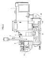
- Fig. 2 is a side view of the turbocompressor in Fig. 1
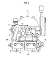
- Fig. 3 is a front view of the turbocompressor in Fig. 1 .
- the turbocompressor according to the embodiment of the present invention is a so-called geared turbocompressor.
- the turbocompressor is a two-stage compressor including a case 46 formed from a casting, and a centrifugal first stage compressing unit 5 as well as a centrifugal second stage compressing unit 6 which are disposed on the case 46.
- the turbocompressor rotates impellers of the first stage and second stage compressing units 5, 6 at a high speed by using an output shaft 2 of a drive motor 1 serving as driving means and through a gear system 3, imparts kinetic energy to air (gas) that is taken in, efficiently decelerates the air thus taken in and converts the air into pressure, and thereby compresses the air.
- the turbocompressor is configured to improve overall compression efficiency by performing intermediate cooling and approaching isothermal compression.
- the drive motor 1 is a so-called flange motor, which is fixed on the case 46 with a flange 1a interposed in between.
- a rotating shaft 4 is disposed parallel to an output shaft 2 of the drive motor 1 and is connected to the output shaft 2 through the gear system (a speed-up gear) 3.
- the first stage compressing unit 5 is provided at an end portion of the rotating shaft 4 near the drive motor 1.
- the second stage compressing unit 6 is provided at the other end of the rotating shaft 4.
- a drive force is transmitted to a central portion of the rotating shaft 4 through the gear system 3.
- the impeller of the first stage compressing unit 5 is attached to the end side of the rotating shaft 4 near the drive motor 1 while the impeller of the second stage compressing unit 6 is attached to the other end side thereof.
- Each of the first stage and second stage compressing units 5, 6 includes a diffuser and a scroll chamber which are located around the impeller attached to the rotating shaft 4. With the impellers subjected to rotation at the high speed, each of the first stage and second stage compressing units 5, 6 accelerates the air (gas), which is sucked in a central portion of the corresponding impeller, outward in the radial direction. The accelerated air passes through the corresponding diffuser and scroll chamber for deceleration, whereby the kinetic energy imparted to the air is converted into pressure energy.
- a large gear (a bull gear) is connected to the output shaft 2 of the drive motor 1.
- a small gear (a pinion gear) meshing with the large gear rotates with increased speed and transmits the drive force to the rotating shaft 4.
- Fig. 4 is a transverse sectional view showing a configuration of the case of the turbocompressor in Fig. 1 .
- the interior of the case 46 is partitioned into first and second cooling areas 44, 45 serving as air-guiding passages, an oil tank 60 filled with lubricant oil necessary for bearings in the rotating shaft 4 and for the gear system 3, and a blowoff silencer chamber (a blow tank) 80.
- a first cooling device (an intercooler) 47 and a second cooling device (an aftercooler) 48 for cooling the air are housed in the first cooling area 44 and the second cooling area 45, respectively.
- the case 46 is formed from the casting integrally with partition plates.
- the partition plates partition the interior of the case 46 into the first cooling area 44, the second cooling area 45, the oil tank 60, and the blowoff silencer chamber 80.
- the blowoff silencer chamber 80 houses a blowoff silencer 82, and is located between the oil tank 60 and the first cooling area 44 as well as the second cooling area 45.
- an intake pipe 7 and an intake filter 8 of the first stage compressing unit 5 are disposed beside the drive motor 1.
- the intake filter 8 is provided for avoiding intake of a foreign object in atmospheric air.
- external air is taken in from the intake pipe 7 by the first stage compressing unit 5, and the external air is compressed by the first stage compressing unit 5.
- the compressed air passes through an air passage unit of the case 46 and is fed from an inlet 44a of the first cooling area 44 into the first cooling area 44 of the case 46.
- the air cooled by the first cooling device 47 is fed from the first cooling area 44 to the second stage compressing unit 6 through an outlet 44b of the first cooling area 44 and piping 9.
- the second stage compressor 6 further compresses the air thus fed, and then feeds the compressed air from an inlet 45a of the second cooling area 45 into the second cooling area 45 of the case 46 through an air passage unit 10 of the case 46.
- the air at about 200°C fed to the second cooling area 45 is cooled down to about 40°C by the second cooling device 48.
- the air cooled by the second cooling device 48 is discharged from the second cooling area 45 through an outlet 45b of the second cooling area 45.
- the air discharged from the outlet 45b of the second cooling area 45 is fed through not-illustrated piping for use in a factory or the like.
- a blowoff valve 83 is opened when a pressure value detected with a sensor installed at an outlet portion of the compressor exceeds a preset value.
- the compressed exhaust air not for use is fed into the blowoff silencer chamber 80 through piping 81 that connects the outlet 45b of the second cooling area 45 and a blowoff silencer chamber inlet 80a.
- the exhaust air fed to the blowoff silencer chamber 80 passes through the blowoff silencer 82 housed in the blowoff silencer chamber 80, and is discharged from a blowoff silencer chamber outlet 80b to the external air.
- the blowoff silencer 82 is configured to reduce noise at a blowoff port of the turbocompressor by silencing and discharging the compressed air inside the blowoff silencer chamber 80 and decelerating a flow rate of the exhaust air.
- the blowoff silencer 82 has a structure including a muffler with a small pressure loss and a duct to which a noise absorption material is attached, and is configured to suppress the noise.
- turbocompressor all other units constituting the turbocompressor, namely, an intake control valve for controlling a flow rate of the air, a control panel for controlling a control valve as well as operation and shutdown, an oil supply system necessary for lubricating the bearings and the gears, a flue gas system configured to keep the interior of the case 46 at negative pressure in order to prevent the lubricant oil from leaking out of the case 46, and the like are installed on the case 46, and thereby space saving is achieved.
- the blowoff silencer 82 is housed in the case 46 and the number of components is thereby reduced.
- the turbocompressor can achieve lower manufacturing costs and can also be installed in a small space together with the blowoff silencer.
- the blowoff silencer chamber 80 is located between the oil tank 60 and the first as well as the second cooling areas 44, 45.
- the case 46 is integrally formed from the casting.
- the present invention is applicable to a turbocompressor used as a power source or for a process in a factory, or more specifically, is applicable to a turbocompressor which is made in a compact size and suppresses noise by building a blowoff silencer chamber inside a case.
Landscapes
- Engineering & Computer Science (AREA)
- Mechanical Engineering (AREA)
- General Engineering & Computer Science (AREA)
- Physics & Mathematics (AREA)
- Thermal Sciences (AREA)
- Structures Of Non-Positive Displacement Pumps (AREA)
- Applications Or Details Of Rotary Compressors (AREA)
Abstract
Description
- The present invention relates to a turbocompressor used as a power source in a factory or a process compressor, or particularly to a turbocompressor provided with a blowoff silencer.
- PTL 1 proposes a two-stage turbocompressor configured to: compress a fluid by a first stage compressor, then further compress the fluid by a second stage compressor, and discharge the fluid. This turbocompressor includes a case formed from a casting, and the first stage compressor and the second stage compressor which are disposed on the case. An impeller of the first stage compressor and an impeller of the second stage compressor are connected to each other with a rotating shaft. The rotating shaft is disposed parallel to an output shaft of a drive motor, and is driven by the drive motor through a gear system located at a central portion of the rotating shaft.
- In the turbocompressor, external air is taken in from an intake port, and the external air is compressed by the first stage compressor and then fed to a first cooling area of the case. A first cooling device is housed in the first cooler. The compressed air is cooled by the first cooling device, fed from the first cooler to the second stage compressor, and further compressed. The air compressed by the second stage compressor is fed to a second cooler of the case. A second cooling device is housed in the second cooler. The compressed air is cooled by the second cooling device and is discharged from the second cooler through an exhaust port.
- The turbocompressor described in PTL 1 is devised in a layout inside the case in order to achieve a reduction in size. The first cooler which houses the first cooling device, the second cooler which houses the second cooling device, and an oil tank which houses lubricant oil are arranged close to each other inside the case.
- In a general centrifugal turbocompressor, pressure at an outlet of the compressor rises when the compressed air becomes excessive in a factory or the like and an amount of the compressed air consumed becomes smaller than an amount of the external air taken-in. In this case, when a pressure value detected by a sensor installed at an outlet portion of the compressor exceeds a preset value, a blowoff valve installed at an outlet of the second cooler is opened and the compressed air is discharged to the external air. In addition, in the above-described compressor, a blowoff silencer is installed at a position between the blowoff valve and a blowoff port to the atmosphere in order to reduce noise caused by opening the blowoff valve.
- [PTL 1] Japanese Patent No.
3470410 - In the meantime, a silencer with a low pressure loss has to be used as the blowoff silencer for the turbocompressor as described above in order to avoid surging. The surging is a phenomenon that backflow of air occurs inside an impeller. The occurrence of the surging leads to severe pulsation and disables normal operation. In this regard, it is common practice to silence and decelerate the air in the blowoff silencer by using a muffler with a small pressure loss, a duct to which a noise absorption material is attached, and the like. However, since a noise reduction effect increases in proportion to the size of the blowoff silencer, there is a problem that a centrifugal turbocompressor made in a compact size cannot suppress blowoff noise sufficiently.
- The present invention has been made in view of the above-described circumstances. An object of the present invention is to provide a turbocompressor capable of being installed in a small space together with a blowoff silencer and sufficiently decreasing noise caused when compressed air is discharged to the external air.
- To solve the problem and to attain the object, a turbocompressor according to an embodiment of the present invention includes any of the following configurations.
- A turbocompressor includes a case, a centrifugal first stage compressing unit disposed on the case, a centrifugal second stage compressing unit disposed on the case, and a driver unit configured to drive the first stage compressing unit and the second stage compressing unit. The case is partitioned into: a first cooling area which houses a first cooling device and to which external air compressed by the first stage compressing unit is fed; a second cooling area which houses a second cooling device and to which air that passes through the first cooling area and is further compressed by the second stage compressing unit is fed; an oil tank which houses lubricant oil that is fed to the driver unit; and a blowoff silencer chamber to which the air that passes through the second cooling area and is discharged to an atmosphere is fed, and, in the interior of the case, the blowoff silencer chamber houses a blowoff silencer and is located between the oil tank and the first cooling area as well as the second cooling area.
- In the turbocompressor having Configuration 1, the case includes partition plates which partition the interior of the case into the first cooling area, the second cooling area, the oil tank, and the blowoff silencer chamber. Moreover, the second cooling area, the oil tank, and the blowoff silencer chamber are integrally formed from a casting.
- Since the turbocompressor has Configuration 1, the blowoff silencer chamber is located between the oil tank and the first cooling area as well as the second cooling area in the interior of the case. Thus, a silencing effect by the blowoff silencer can be increased. In addition, since there is an air layer between the oil tank and the first as well as the second cooling areas, heat transfer occurring between the air inside the cooling areas and the lubricant oil inside the oil tank is suppressed.
- Moreover, the turbocompressor can achieve lower manufacturing costs by a reduction in the number of components, and can be installed in a small space together with the blowoff silencer.
- Meanwhile, since the turbocompressor has Configuration 2, the case is formed from the casting integrally with the partition plates to partition the interior of the case. Thus, the silencing effect of the blowoff silencer can be increased.
- In other words, it is possible to provide the turbocompressor, which can be installed in a small space together with the blowoff silencer, and sufficiently reduce noise when exhaust air is discharged to the external air.
-
- [
Fig. 1 ]
Fig. 1 is a plan view of a turbocompressor according to an embodiment of the present invention. - [
Fig. 2 ]
Fig. 2 is a side view of the turbocompressor inFig. 1 . - [
Fig. 3 ]
Fig. 3 is a front view of the turbocompressor inFig. 1 . - [
Fig. 4 ]
Fig. 4 is a transverse sectional view showing a configuration of a case of the turbocompressor inFig. 1 . - An embodiment of the present invention will be described below on the basis of the drawings.
-
Fig. 1 is a plan view of a turbocompressor according to an embodiment of the present invention,Fig. 2 is a side view of the turbocompressor inFig. 1 , andFig. 3 is a front view of the turbocompressor inFig. 1 . - The turbocompressor according to the embodiment of the present invention is a so-called geared turbocompressor. As shown in
Fig. 1 to Fig. 3 , the turbocompressor is a two-stage compressor including acase 46 formed from a casting, and a centrifugal first stage compressing unit 5 as well as a centrifugal second stage compressing unit 6 which are disposed on thecase 46. - The turbocompressor rotates impellers of the first stage and second stage compressing units 5, 6 at a high speed by using an output shaft 2 of a drive motor 1 serving as driving means and through a
gear system 3, imparts kinetic energy to air (gas) that is taken in, efficiently decelerates the air thus taken in and converts the air into pressure, and thereby compresses the air. The turbocompressor is configured to improve overall compression efficiency by performing intermediate cooling and approaching isothermal compression. - The drive motor 1 is a so-called flange motor, which is fixed on the
case 46 with aflange 1a interposed in between. A rotatingshaft 4 is disposed parallel to an output shaft 2 of the drive motor 1 and is connected to the output shaft 2 through the gear system (a speed-up gear) 3. The first stage compressing unit 5 is provided at an end portion of the rotatingshaft 4 near the drive motor 1. The second stage compressing unit 6 is provided at the other end of the rotatingshaft 4. A drive force is transmitted to a central portion of the rotatingshaft 4 through thegear system 3. The impeller of the first stage compressing unit 5 is attached to the end side of the rotatingshaft 4 near the drive motor 1 while the impeller of the second stage compressing unit 6 is attached to the other end side thereof. - Each of the first stage and second stage compressing units 5, 6 includes a diffuser and a scroll chamber which are located around the impeller attached to the rotating
shaft 4. With the impellers subjected to rotation at the high speed, each of the first stage and second stage compressing units 5, 6 accelerates the air (gas), which is sucked in a central portion of the corresponding impeller, outward in the radial direction. The accelerated air passes through the corresponding diffuser and scroll chamber for deceleration, whereby the kinetic energy imparted to the air is converted into pressure energy. - In the
gear system 3, a large gear (a bull gear) is connected to the output shaft 2 of the drive motor 1. A small gear (a pinion gear) meshing with the large gear rotates with increased speed and transmits the drive force to therotating shaft 4. -
Fig. 4 is a transverse sectional view showing a configuration of the case of the turbocompressor inFig. 1 . - The interior of the
case 46 is partitioned into first andsecond cooling areas oil tank 60 filled with lubricant oil necessary for bearings in therotating shaft 4 and for thegear system 3, and a blowoff silencer chamber (a blow tank) 80. A first cooling device (an intercooler) 47 and a second cooling device (an aftercooler) 48 for cooling the air are housed in thefirst cooling area 44 and thesecond cooling area 45, respectively. Thecase 46 is formed from the casting integrally with partition plates. Here, the partition plates partition the interior of thecase 46 into thefirst cooling area 44, thesecond cooling area 45, theoil tank 60, and theblowoff silencer chamber 80. Theblowoff silencer chamber 80 houses ablowoff silencer 82, and is located between theoil tank 60 and thefirst cooling area 44 as well as thesecond cooling area 45. - Meanwhile, as shown in
Fig. 1 , an intake pipe 7 and anintake filter 8 of the first stage compressing unit 5 are disposed beside the drive motor 1. Theintake filter 8 is provided for avoiding intake of a foreign object in atmospheric air. In the turbocompressor, external air is taken in from the intake pipe 7 by the first stage compressing unit 5, and the external air is compressed by the first stage compressing unit 5. Then, as shown inFig. 4 , the compressed air passes through an air passage unit of thecase 46 and is fed from aninlet 44a of thefirst cooling area 44 into thefirst cooling area 44 of thecase 46. - While the compressed air is heated to about 200°C at the time of being fed to the
first cooling area 44, the air is cooled down to about 40°C by thefirst cooling device 47. The air cooled by thefirst cooling device 47 is fed from thefirst cooling area 44 to the second stage compressing unit 6 through anoutlet 44b of thefirst cooling area 44 andpiping 9. - The second stage compressor 6 further compresses the air thus fed, and then feeds the compressed air from an
inlet 45a of thesecond cooling area 45 into thesecond cooling area 45 of thecase 46 through anair passage unit 10 of thecase 46. The air at about 200°C fed to thesecond cooling area 45 is cooled down to about 40°C by thesecond cooling device 48. The air cooled by thesecond cooling device 48 is discharged from thesecond cooling area 45 through anoutlet 45b of thesecond cooling area 45. The air discharged from theoutlet 45b of thesecond cooling area 45 is fed through not-illustrated piping for use in a factory or the like. - In the turbocompressor, pressure at an outlet of the compressor rises when the compressed air becomes excessive in a factory or the like and an amount of the compressed air consumed becomes smaller than an amount of the external air taken-in. Then, a
blowoff valve 83 is opened when a pressure value detected with a sensor installed at an outlet portion of the compressor exceeds a preset value. In this case, the compressed exhaust air not for use is fed into theblowoff silencer chamber 80 through piping 81 that connects theoutlet 45b of thesecond cooling area 45 and a blowoffsilencer chamber inlet 80a. The exhaust air fed to theblowoff silencer chamber 80 passes through theblowoff silencer 82 housed in theblowoff silencer chamber 80, and is discharged from a blowoffsilencer chamber outlet 80b to the external air. Theblowoff silencer 82 is configured to reduce noise at a blowoff port of the turbocompressor by silencing and discharging the compressed air inside theblowoff silencer chamber 80 and decelerating a flow rate of the exhaust air. Theblowoff silencer 82 has a structure including a muffler with a small pressure loss and a duct to which a noise absorption material is attached, and is configured to suppress the noise. - In the turbocompressor, all other units constituting the turbocompressor, namely, an intake control valve for controlling a flow rate of the air, a control panel for controlling a control valve as well as operation and shutdown, an oil supply system necessary for lubricating the bearings and the gears, a flue gas system configured to keep the interior of the
case 46 at negative pressure in order to prevent the lubricant oil from leaking out of thecase 46, and the like are installed on thecase 46, and thereby space saving is achieved. - Moreover, in the turbocompressor, the
blowoff silencer 82 is housed in thecase 46 and the number of components is thereby reduced. Thus, the turbocompressor can achieve lower manufacturing costs and can also be installed in a small space together with the blowoff silencer. - Furthermore, in the turbocompressor, the
blowoff silencer chamber 80 is located between theoil tank 60 and the first as well as thesecond cooling areas case 46 is integrally formed from the casting. Thus, it is possible to increase a silencing effect of theblowoff silencer 82. When the compressed air is discharged to the atmosphere, its sound pressure level reaches 120 dB or higher. This blowoff sound can be shielded and attenuated by theblowoff silencer chamber 80. Thus, it is possible to sufficiently reduce the noise outside the turbocompressor. - If the
oil tank 60 is built in thecase 46, heat exchange will occur at its partition walls with the first andsecond cooling areas oil tank 60 is suppressed, and it is therefore unnecessary to increase the capacity of the oil cooler. In addition, no deterioration in efficiency of the compressor occurs due to a rise in temperature of the air. - The present invention is applicable to a turbocompressor used as a power source or for a process in a factory, or more specifically, is applicable to a turbocompressor which is made in a compact size and suppresses noise by building a blowoff silencer chamber inside a case.
Claims (2)
- A turbocompressor comprising:a case;a centrifugal first stage compressing unit disposed on the case;a centrifugal second stage compressing unit disposed on the case; anda driver unit configured to drive the first stage compressing unit and the second stage compressing unit, whereinthe case is partitioned into a first cooling area which houses a first cooling device and to which external air compressed by the first stage compressing unit is fed, a second cooling area which houses a second cooling device and to which air that passes through the first cooling area and is further compressed by the second stage compressing unit is fed, an oil tank which houses lubricant oil to be fed to the driver unit, and a blowoff silencer chamber to which the air that passes through the second cooling area and is to be discharged to atmosphere is fed, andthe blowoff silencer chamber houses a blowoff silencer, and is located between the oil tank and the first cooling area as well as the second cooling area in an interior of the case.
- The turbocompressor of claim 1, wherein
the case comprises partition plates which partition the interior of the case into the first cooling area, the second cooling area, the oil tank, and the blowoff silencer chamber, and
the first cooling area, the second cooling area, the oil tank, and the blowoff silencer chamber are integrally formed from a casting.
Applications Claiming Priority (2)
| Application Number | Priority Date | Filing Date | Title |
|---|---|---|---|
| JP2011142600A JP5672171B2 (en) | 2011-06-28 | 2011-06-28 | Turbo compressor |
| PCT/JP2012/066239 WO2013002204A1 (en) | 2011-06-28 | 2012-06-26 | Turbocompressor |
Publications (3)
| Publication Number | Publication Date |
|---|---|
| EP2728198A1 true EP2728198A1 (en) | 2014-05-07 |
| EP2728198A4 EP2728198A4 (en) | 2015-04-15 |
| EP2728198B1 EP2728198B1 (en) | 2017-06-14 |
Family
ID=47424096
Family Applications (1)
| Application Number | Title | Priority Date | Filing Date |
|---|---|---|---|
| EP12804727.1A Active EP2728198B1 (en) | 2011-06-28 | 2012-06-26 | Turbocompressor |
Country Status (6)
| Country | Link |
|---|---|
| US (1) | US20140105734A1 (en) |
| EP (1) | EP2728198B1 (en) |
| JP (1) | JP5672171B2 (en) |
| KR (1) | KR20140018416A (en) |
| CN (1) | CN103620230B (en) |
| WO (1) | WO2013002204A1 (en) |
Families Citing this family (3)
| Publication number | Priority date | Publication date | Assignee | Title |
|---|---|---|---|---|
| KR102592232B1 (en) | 2016-07-15 | 2023-10-20 | 한화파워시스템 주식회사 | Air cooling system for fluidic machine |
| CN107246388A (en) * | 2017-07-11 | 2017-10-13 | 温州胜波汽车零部件有限公司 | Scroll compressor component and two-stage compression oil-free scroll air compressor machine |
| US11261871B2 (en) | 2018-12-13 | 2022-03-01 | Regal Beloit America, Inc. | Dual stage blower assembly |
Family Cites Families (11)
| Publication number | Priority date | Publication date | Assignee | Title |
|---|---|---|---|---|
| JPS521554A (en) * | 1975-06-24 | 1977-01-07 | Hitachi Ltd | Heat exchanger for turbo fluid machine |
| JP3470410B2 (en) | 1994-09-28 | 2003-11-25 | 石川島播磨重工業株式会社 | Turbo compressor |
| US6692235B2 (en) * | 2001-07-30 | 2004-02-17 | Cooper Cameron Corporation | Air cooled packaged multi-stage centrifugal compressor system |
| JP4082009B2 (en) * | 2001-09-25 | 2008-04-30 | 株式会社日立プラントテクノロジー | Turbo compressor |
| EP1997548A1 (en) * | 2003-03-26 | 2008-12-03 | IHI Corporation | Suction filter |
| JP4635408B2 (en) * | 2003-03-26 | 2011-02-23 | 株式会社Ihi | Suction filter |
| JP4483194B2 (en) * | 2003-04-03 | 2010-06-16 | 株式会社Ihi | Turbo compressor and packaging method thereof |
| JP2005248832A (en) * | 2004-03-04 | 2005-09-15 | Ishikawajima Harima Heavy Ind Co Ltd | Turbo compressor |
| GB2443421B (en) * | 2006-08-30 | 2009-02-18 | Compair Uk Ltd | Improvements in compressors units |
| JP5327865B2 (en) * | 2009-09-10 | 2013-10-30 | Necカシオモバイルコミュニケーションズ株式会社 | Portable terminal device and program |
| JP5668371B2 (en) * | 2010-08-31 | 2015-02-12 | 株式会社Ihi | Turbo compressor |
-
2011
- 2011-06-28 JP JP2011142600A patent/JP5672171B2/en active Active
-
2012
- 2012-06-26 KR KR1020137035154A patent/KR20140018416A/en not_active Ceased
- 2012-06-26 CN CN201280031377.2A patent/CN103620230B/en active Active
- 2012-06-26 WO PCT/JP2012/066239 patent/WO2013002204A1/en not_active Ceased
- 2012-06-26 EP EP12804727.1A patent/EP2728198B1/en active Active
-
2013
- 2013-12-18 US US14/132,023 patent/US20140105734A1/en not_active Abandoned
Also Published As
| Publication number | Publication date |
|---|---|
| KR20140018416A (en) | 2014-02-12 |
| US20140105734A1 (en) | 2014-04-17 |
| EP2728198A4 (en) | 2015-04-15 |
| WO2013002204A1 (en) | 2013-01-03 |
| CN103620230B (en) | 2016-03-02 |
| JP5672171B2 (en) | 2015-02-18 |
| EP2728198B1 (en) | 2017-06-14 |
| CN103620230A (en) | 2014-03-05 |
| JP2013011174A (en) | 2013-01-17 |
Similar Documents
| Publication | Publication Date | Title |
|---|---|---|
| US8313312B2 (en) | Screw compressor | |
| JP5774455B2 (en) | Oil-free compressor | |
| CN105222980A (en) | A kind of wind tunnel body pumped vacuum systems | |
| WO2015027825A1 (en) | Multi-stage centrifugal compressor and air conditioning unit | |
| EP2728198B1 (en) | Turbocompressor | |
| CN111120364A (en) | High-speed centrifugal compressor | |
| JP2007332826A (en) | Centrifugal compressor | |
| CN205669505U (en) | A kind of centrifugal compressor of band Series Connection Type Dry Gas | |
| JP2015172371A (en) | Oilless screw compressor | |
| CN114576178A (en) | An integrated high-speed centrifugal compressor | |
| CN103899538B (en) | A kind of twin-screw two-stage supercharging air compressor | |
| CN201723477U (en) | Rectangular low-noise centrifugal pipeline fan | |
| CN219911153U (en) | Internally cooled Roots pump device | |
| JP7218319B2 (en) | air compressor | |
| JP4745208B2 (en) | Oil-free screw compressor | |
| CN220748630U (en) | Magnetic suspension air compressor | |
| JP4876868B2 (en) | Turbo compressor | |
| CN219691772U (en) | Oilless air compressor | |
| CN217002314U (en) | Integrated high-speed centrifugal compressor | |
| CN101545471A (en) | Pneumatic diving pump | |
| WO2014192851A1 (en) | Two-shaft rotary pump | |
| CN201090442Y (en) | Air blasting or air inducing equipment | |
| CN204327450U (en) | Refrigeration compressor body | |
| CN104728115A (en) | Industrial refrigeration compressor body | |
| CN215058166U (en) | Permanent magnet frequency conversion low-voltage screw machine |
Legal Events
| Date | Code | Title | Description |
|---|---|---|---|
| PUAI | Public reference made under article 153(3) epc to a published international application that has entered the european phase |
Free format text: ORIGINAL CODE: 0009012 |
|
| 17P | Request for examination filed |
Effective date: 20140109 |
|
| AK | Designated contracting states |
Kind code of ref document: A1 Designated state(s): AL AT BE BG CH CY CZ DE DK EE ES FI FR GB GR HR HU IE IS IT LI LT LU LV MC MK MT NL NO PL PT RO RS SE SI SK SM TR |
|
| DAX | Request for extension of the european patent (deleted) | ||
| RA4 | Supplementary search report drawn up and despatched (corrected) |
Effective date: 20150316 |
|
| RIC1 | Information provided on ipc code assigned before grant |
Ipc: F04D 17/12 20060101ALI20150310BHEP Ipc: F04D 29/66 20060101ALI20150310BHEP Ipc: F04D 29/58 20060101AFI20150310BHEP |
|
| RIC1 | Information provided on ipc code assigned before grant |
Ipc: F04D 29/58 20060101AFI20161213BHEP Ipc: F04D 25/16 20060101ALI20161213BHEP Ipc: F04D 17/12 20060101ALI20161213BHEP Ipc: F04D 29/66 20060101ALI20161213BHEP |
|
| GRAP | Despatch of communication of intention to grant a patent |
Free format text: ORIGINAL CODE: EPIDOSNIGR1 |
|
| INTG | Intention to grant announced |
Effective date: 20170126 |
|
| GRAS | Grant fee paid |
Free format text: ORIGINAL CODE: EPIDOSNIGR3 |
|
| GRAA | (expected) grant |
Free format text: ORIGINAL CODE: 0009210 |
|
| AK | Designated contracting states |
Kind code of ref document: B1 Designated state(s): AL AT BE BG CH CY CZ DE DK EE ES FI FR GB GR HR HU IE IS IT LI LT LU LV MC MK MT NL NO PL PT RO RS SE SI SK SM TR |
|
| REG | Reference to a national code |
Ref country code: GB Ref legal event code: FG4D |
|
| REG | Reference to a national code |
Ref country code: CH Ref legal event code: EP Ref country code: AT Ref legal event code: REF Ref document number: 901268 Country of ref document: AT Kind code of ref document: T Effective date: 20170615 |
|
| REG | Reference to a national code |
Ref country code: IE Ref legal event code: FG4D |
|
| REG | Reference to a national code |
Ref country code: DE Ref legal event code: R096 Ref document number: 602012033494 Country of ref document: DE |
|
| REG | Reference to a national code |
Ref country code: NL Ref legal event code: MP Effective date: 20170614 |
|
| REG | Reference to a national code |
Ref country code: LT Ref legal event code: MG4D |
|
| PG25 | Lapsed in a contracting state [announced via postgrant information from national office to epo] |
Ref country code: FI Free format text: LAPSE BECAUSE OF FAILURE TO SUBMIT A TRANSLATION OF THE DESCRIPTION OR TO PAY THE FEE WITHIN THE PRESCRIBED TIME-LIMIT Effective date: 20170614 Ref country code: NO Free format text: LAPSE BECAUSE OF FAILURE TO SUBMIT A TRANSLATION OF THE DESCRIPTION OR TO PAY THE FEE WITHIN THE PRESCRIBED TIME-LIMIT Effective date: 20170914 Ref country code: LT Free format text: LAPSE BECAUSE OF FAILURE TO SUBMIT A TRANSLATION OF THE DESCRIPTION OR TO PAY THE FEE WITHIN THE PRESCRIBED TIME-LIMIT Effective date: 20170614 Ref country code: HR Free format text: LAPSE BECAUSE OF FAILURE TO SUBMIT A TRANSLATION OF THE DESCRIPTION OR TO PAY THE FEE WITHIN THE PRESCRIBED TIME-LIMIT Effective date: 20170614 Ref country code: GR Free format text: LAPSE BECAUSE OF FAILURE TO SUBMIT A TRANSLATION OF THE DESCRIPTION OR TO PAY THE FEE WITHIN THE PRESCRIBED TIME-LIMIT Effective date: 20170915 |
|
| REG | Reference to a national code |
Ref country code: AT Ref legal event code: MK05 Ref document number: 901268 Country of ref document: AT Kind code of ref document: T Effective date: 20170614 |
|
| PG25 | Lapsed in a contracting state [announced via postgrant information from national office to epo] |
Ref country code: BG Free format text: LAPSE BECAUSE OF FAILURE TO SUBMIT A TRANSLATION OF THE DESCRIPTION OR TO PAY THE FEE WITHIN THE PRESCRIBED TIME-LIMIT Effective date: 20170914 Ref country code: LV Free format text: LAPSE BECAUSE OF FAILURE TO SUBMIT A TRANSLATION OF THE DESCRIPTION OR TO PAY THE FEE WITHIN THE PRESCRIBED TIME-LIMIT Effective date: 20170614 Ref country code: NL Free format text: LAPSE BECAUSE OF FAILURE TO SUBMIT A TRANSLATION OF THE DESCRIPTION OR TO PAY THE FEE WITHIN THE PRESCRIBED TIME-LIMIT Effective date: 20170614 Ref country code: RS Free format text: LAPSE BECAUSE OF FAILURE TO SUBMIT A TRANSLATION OF THE DESCRIPTION OR TO PAY THE FEE WITHIN THE PRESCRIBED TIME-LIMIT Effective date: 20170614 Ref country code: SE Free format text: LAPSE BECAUSE OF FAILURE TO SUBMIT A TRANSLATION OF THE DESCRIPTION OR TO PAY THE FEE WITHIN THE PRESCRIBED TIME-LIMIT Effective date: 20170614 |
|
| REG | Reference to a national code |
Ref country code: DE Ref legal event code: R119 Ref document number: 602012033494 Country of ref document: DE |
|
| PG25 | Lapsed in a contracting state [announced via postgrant information from national office to epo] |
Ref country code: EE Free format text: LAPSE BECAUSE OF FAILURE TO SUBMIT A TRANSLATION OF THE DESCRIPTION OR TO PAY THE FEE WITHIN THE PRESCRIBED TIME-LIMIT Effective date: 20170614 Ref country code: AT Free format text: LAPSE BECAUSE OF FAILURE TO SUBMIT A TRANSLATION OF THE DESCRIPTION OR TO PAY THE FEE WITHIN THE PRESCRIBED TIME-LIMIT Effective date: 20170614 Ref country code: RO Free format text: LAPSE BECAUSE OF FAILURE TO SUBMIT A TRANSLATION OF THE DESCRIPTION OR TO PAY THE FEE WITHIN THE PRESCRIBED TIME-LIMIT Effective date: 20170614 Ref country code: CZ Free format text: LAPSE BECAUSE OF FAILURE TO SUBMIT A TRANSLATION OF THE DESCRIPTION OR TO PAY THE FEE WITHIN THE PRESCRIBED TIME-LIMIT Effective date: 20170614 Ref country code: SK Free format text: LAPSE BECAUSE OF FAILURE TO SUBMIT A TRANSLATION OF THE DESCRIPTION OR TO PAY THE FEE WITHIN THE PRESCRIBED TIME-LIMIT Effective date: 20170614 |
|
| REG | Reference to a national code |
Ref country code: CH Ref legal event code: PL |
|
| PG25 | Lapsed in a contracting state [announced via postgrant information from national office to epo] |
Ref country code: IS Free format text: LAPSE BECAUSE OF FAILURE TO SUBMIT A TRANSLATION OF THE DESCRIPTION OR TO PAY THE FEE WITHIN THE PRESCRIBED TIME-LIMIT Effective date: 20171014 Ref country code: PL Free format text: LAPSE BECAUSE OF FAILURE TO SUBMIT A TRANSLATION OF THE DESCRIPTION OR TO PAY THE FEE WITHIN THE PRESCRIBED TIME-LIMIT Effective date: 20170614 Ref country code: ES Free format text: LAPSE BECAUSE OF FAILURE TO SUBMIT A TRANSLATION OF THE DESCRIPTION OR TO PAY THE FEE WITHIN THE PRESCRIBED TIME-LIMIT Effective date: 20170614 Ref country code: IT Free format text: LAPSE BECAUSE OF FAILURE TO SUBMIT A TRANSLATION OF THE DESCRIPTION OR TO PAY THE FEE WITHIN THE PRESCRIBED TIME-LIMIT Effective date: 20170614 Ref country code: SM Free format text: LAPSE BECAUSE OF FAILURE TO SUBMIT A TRANSLATION OF THE DESCRIPTION OR TO PAY THE FEE WITHIN THE PRESCRIBED TIME-LIMIT Effective date: 20170614 |
|
| REG | Reference to a national code |
Ref country code: IE Ref legal event code: MM4A |
|
| PG25 | Lapsed in a contracting state [announced via postgrant information from national office to epo] |
Ref country code: MC Free format text: LAPSE BECAUSE OF FAILURE TO SUBMIT A TRANSLATION OF THE DESCRIPTION OR TO PAY THE FEE WITHIN THE PRESCRIBED TIME-LIMIT Effective date: 20170614 |
|
| PLBE | No opposition filed within time limit |
Free format text: ORIGINAL CODE: 0009261 |
|
| STAA | Information on the status of an ep patent application or granted ep patent |
Free format text: STATUS: NO OPPOSITION FILED WITHIN TIME LIMIT |
|
| PG25 | Lapsed in a contracting state [announced via postgrant information from national office to epo] |
Ref country code: LI Free format text: LAPSE BECAUSE OF NON-PAYMENT OF DUE FEES Effective date: 20170630 Ref country code: LU Free format text: LAPSE BECAUSE OF NON-PAYMENT OF DUE FEES Effective date: 20170626 Ref country code: DK Free format text: LAPSE BECAUSE OF FAILURE TO SUBMIT A TRANSLATION OF THE DESCRIPTION OR TO PAY THE FEE WITHIN THE PRESCRIBED TIME-LIMIT Effective date: 20170614 Ref country code: IE Free format text: LAPSE BECAUSE OF NON-PAYMENT OF DUE FEES Effective date: 20170626 Ref country code: CH Free format text: LAPSE BECAUSE OF NON-PAYMENT OF DUE FEES Effective date: 20170630 Ref country code: DE Free format text: LAPSE BECAUSE OF NON-PAYMENT OF DUE FEES Effective date: 20180103 |
|
| REG | Reference to a national code |
Ref country code: FR Ref legal event code: ST Effective date: 20180409 |
|
| 26N | No opposition filed |
Effective date: 20180315 |
|
| GBPC | Gb: european patent ceased through non-payment of renewal fee |
Effective date: 20170914 |
|
| PG25 | Lapsed in a contracting state [announced via postgrant information from national office to epo] |
Ref country code: GB Free format text: LAPSE BECAUSE OF NON-PAYMENT OF DUE FEES Effective date: 20170914 |
|
| PG25 | Lapsed in a contracting state [announced via postgrant information from national office to epo] |
Ref country code: SI Free format text: LAPSE BECAUSE OF FAILURE TO SUBMIT A TRANSLATION OF THE DESCRIPTION OR TO PAY THE FEE WITHIN THE PRESCRIBED TIME-LIMIT Effective date: 20170614 Ref country code: FR Free format text: LAPSE BECAUSE OF NON-PAYMENT OF DUE FEES Effective date: 20170816 |
|
| REG | Reference to a national code |
Ref country code: BE Ref legal event code: PD Owner name: IHI ROTATING MACHINERY ENGINEERING CO., LTD.; JP Free format text: DETAILS ASSIGNMENT: CHANGE OF OWNER(S), CESSION; FORMER OWNER NAME: IHI CORPORATION Effective date: 20180704 |
|
| PG25 | Lapsed in a contracting state [announced via postgrant information from national office to epo] |
Ref country code: MT Free format text: LAPSE BECAUSE OF NON-PAYMENT OF DUE FEES Effective date: 20170626 |
|
| PG25 | Lapsed in a contracting state [announced via postgrant information from national office to epo] |
Ref country code: HU Free format text: LAPSE BECAUSE OF FAILURE TO SUBMIT A TRANSLATION OF THE DESCRIPTION OR TO PAY THE FEE WITHIN THE PRESCRIBED TIME-LIMIT; INVALID AB INITIO Effective date: 20120626 |
|
| PG25 | Lapsed in a contracting state [announced via postgrant information from national office to epo] |
Ref country code: CY Free format text: LAPSE BECAUSE OF NON-PAYMENT OF DUE FEES Effective date: 20170614 |
|
| PG25 | Lapsed in a contracting state [announced via postgrant information from national office to epo] |
Ref country code: MK Free format text: LAPSE BECAUSE OF FAILURE TO SUBMIT A TRANSLATION OF THE DESCRIPTION OR TO PAY THE FEE WITHIN THE PRESCRIBED TIME-LIMIT Effective date: 20170614 |
|
| PG25 | Lapsed in a contracting state [announced via postgrant information from national office to epo] |
Ref country code: PT Free format text: LAPSE BECAUSE OF FAILURE TO SUBMIT A TRANSLATION OF THE DESCRIPTION OR TO PAY THE FEE WITHIN THE PRESCRIBED TIME-LIMIT Effective date: 20170614 |
|
| PG25 | Lapsed in a contracting state [announced via postgrant information from national office to epo] |
Ref country code: AL Free format text: LAPSE BECAUSE OF FAILURE TO SUBMIT A TRANSLATION OF THE DESCRIPTION OR TO PAY THE FEE WITHIN THE PRESCRIBED TIME-LIMIT Effective date: 20170614 |
|
| PGFP | Annual fee paid to national office [announced via postgrant information from national office to epo] |
Ref country code: BE Payment date: 20250516 Year of fee payment: 14 |
|
| PGFP | Annual fee paid to national office [announced via postgrant information from national office to epo] |
Ref country code: TR Payment date: 20250620 Year of fee payment: 14 |