EP2728177A1 - Windmill repair timing determination support device and repair timing determination support method - Google Patents
Windmill repair timing determination support device and repair timing determination support method Download PDFInfo
- Publication number
- EP2728177A1 EP2728177A1 EP12804480.7A EP12804480A EP2728177A1 EP 2728177 A1 EP2728177 A1 EP 2728177A1 EP 12804480 A EP12804480 A EP 12804480A EP 2728177 A1 EP2728177 A1 EP 2728177A1
- Authority
- EP
- European Patent Office
- Prior art keywords
- repair
- output
- wind turbine
- cost
- case
- Prior art date
- Legal status (The legal status is an assumption and is not a legal conclusion. Google has not performed a legal analysis and makes no representation as to the accuracy of the status listed.)
- Withdrawn
Links
- 238000000034 method Methods 0.000 title claims description 10
- 230000005611 electricity Effects 0.000 claims abstract description 55
- 230000006735 deficit Effects 0.000 claims abstract description 48
- 230000001932 seasonal effect Effects 0.000 claims description 3
- 230000005856 abnormality Effects 0.000 abstract description 14
- 238000012544 monitoring process Methods 0.000 description 28
- 238000010248 power generation Methods 0.000 description 16
- 238000012423 maintenance Methods 0.000 description 14
- 238000001514 detection method Methods 0.000 description 10
- 230000003247 decreasing effect Effects 0.000 description 8
- 238000007689 inspection Methods 0.000 description 6
- 239000002184 metal Substances 0.000 description 6
- 238000013480 data collection Methods 0.000 description 5
- 238000004891 communication Methods 0.000 description 3
- 238000003745 diagnosis Methods 0.000 description 2
- 238000010586 diagram Methods 0.000 description 2
- 238000005461 lubrication Methods 0.000 description 2
- 239000002245 particle Substances 0.000 description 2
- 238000012545 processing Methods 0.000 description 2
- 238000006243 chemical reaction Methods 0.000 description 1
- 230000006866 deterioration Effects 0.000 description 1
- 230000000694 effects Effects 0.000 description 1
- 239000000284 extract Substances 0.000 description 1
- 238000011084 recovery Methods 0.000 description 1
- 238000010187 selection method Methods 0.000 description 1
- 230000001131 transforming effect Effects 0.000 description 1
Images



Classifications
-
- F—MECHANICAL ENGINEERING; LIGHTING; HEATING; WEAPONS; BLASTING
- F03—MACHINES OR ENGINES FOR LIQUIDS; WIND, SPRING, OR WEIGHT MOTORS; PRODUCING MECHANICAL POWER OR A REACTIVE PROPULSIVE THRUST, NOT OTHERWISE PROVIDED FOR
- F03D—WIND MOTORS
- F03D7/00—Controlling wind motors
- F03D7/02—Controlling wind motors the wind motors having rotation axis substantially parallel to the air flow entering the rotor
- F03D7/04—Automatic control; Regulation
- F03D7/042—Automatic control; Regulation by means of an electrical or electronic controller
-
- F—MECHANICAL ENGINEERING; LIGHTING; HEATING; WEAPONS; BLASTING
- F03—MACHINES OR ENGINES FOR LIQUIDS; WIND, SPRING, OR WEIGHT MOTORS; PRODUCING MECHANICAL POWER OR A REACTIVE PROPULSIVE THRUST, NOT OTHERWISE PROVIDED FOR
- F03D—WIND MOTORS
- F03D80/00—Details, components or accessories not provided for in groups F03D1/00 - F03D17/00
- F03D80/50—Maintenance or repair
-
- F—MECHANICAL ENGINEERING; LIGHTING; HEATING; WEAPONS; BLASTING
- F05—INDEXING SCHEMES RELATING TO ENGINES OR PUMPS IN VARIOUS SUBCLASSES OF CLASSES F01-F04
- F05B—INDEXING SCHEME RELATING TO WIND, SPRING, WEIGHT, INERTIA OR LIKE MOTORS, TO MACHINES OR ENGINES FOR LIQUIDS COVERED BY SUBCLASSES F03B, F03D AND F03G
- F05B2270/00—Control
- F05B2270/10—Purpose of the control system
- F05B2270/20—Purpose of the control system to optimise the performance of a machine
-
- Y—GENERAL TAGGING OF NEW TECHNOLOGICAL DEVELOPMENTS; GENERAL TAGGING OF CROSS-SECTIONAL TECHNOLOGIES SPANNING OVER SEVERAL SECTIONS OF THE IPC; TECHNICAL SUBJECTS COVERED BY FORMER USPC CROSS-REFERENCE ART COLLECTIONS [XRACs] AND DIGESTS
- Y02—TECHNOLOGIES OR APPLICATIONS FOR MITIGATION OR ADAPTATION AGAINST CLIMATE CHANGE
- Y02E—REDUCTION OF GREENHOUSE GAS [GHG] EMISSIONS, RELATED TO ENERGY GENERATION, TRANSMISSION OR DISTRIBUTION
- Y02E10/00—Energy generation through renewable energy sources
- Y02E10/70—Wind energy
- Y02E10/72—Wind turbines with rotation axis in wind direction
Definitions
- the present invention relates to a technique for determining an appropriate repair timing of a wind turbine.
- the stop period of the wind turbine generator apparatus from the trouble to the recovery becomes longer, which results in a problem of further decreasing of the electricity selling income.
- Patent Literature 1 For the purpose of solving the above problem, in Patent Literature 1, a technique for a monitoring apparatus of wind turbine generator equipment is described.
- the trouble of a part is predicted in advance, by determining whether or not the actual operation condition reaches the operation amount at which maintenance is required, based on: the actual operation history of the wind turbine generator equipment obtained by an operation state monitoring means; and the maintenance condition of the wind turbine equipment set in advance.
- Patent Literature 1 Japanese Patent Application Publication JP2006-342766A
- the wind condition varies depending on the seasons, and a strong wind tends to blow in winter. Therefore, in the wind turbine generator, the power generation amount has a tendency to be larger in winter, and be small in summer. As a result, if the wind turbine generator apparatus is stopped for maintenance in winter, the decrease amount of the electricity selling income is large. It is desired to reduce the maintenance which requires the stop of the wind turbine generator apparatus in winter, with ensuring the soundness of the wind turbine generator apparatus.
- main parts of a wind turbine generator apparatus are installed mainly in high places, such as the nacelle mounted on the upper edge of the tower installed on the bedding, the rotor head mounted on the nacelle, and the like. Therefore, for implementing a work for repairing or replacing parts of the wind turbine generator apparatus, work in high places using crane equipment and the like is required.
- the wind turbine generator apparatus is an apparatus for transforming the wind power into the electric power, so that it is installed in a windy location. Further, as mentioned above, main parts of the wind turbine generator apparatus are installed in high places, which is exposed to wind.
- the present invention is invented from the above backgrounds, and an object of the present invention is to provide a work timing selection apparatus and a work timing selection method which enables the specification of an appropriate timing for implementing a work for a wind turbine generator apparatus.
- a repair timing determination support apparatus includes: a repair cost storage section configured to store a repair cost estimation value being a time-series estimation value of a cost for repairing a part of a wind turbine from an occurrence of a predetermined behavior of the part to a repair of the part for a case where the wind turbine operates at a first output and a case where the wind turbine operates at a second output lower than the first output; an electricity selling income storage section configured to store an electricity selling income estimation value being a time-series estimation value of an income from electricity selling of an electricity generated by the wind turbine for a case of the first output and a case of the second output; and a total surplus/deficit calculation section configured to calculate and output a total surplus/deficit from the occurrence of the predetermined behavior to the repair of the part for a case where the wind turbine operates at the first output and a case where the wind turbine operates at the second output at a plurality of repairing candidate timings by referring to the repair cost storage section and the electricity selling
- a repair timing determination support method includes: a repair cost calculation step of calculating a repair cost estimation value being a time-series estimation value of a cost for repairing a part of a wind turbine from an occurrence of a predetermined behavior of the part to a repair of the part for a case where the wind turbine operates at a first output and a case where the wind turbine operates at a second output lower than the first output; an electricity selling income calculation step of calculating an electricity selling income estimation value being a time-series estimation value of an income from electricity selling of an electricity generated by the wind turbine for a case of the first output and a case of the second output; and a total surplus/deficit calculation step of calculating and outputting a total surplus/deficit from the occurrence of the predetermined behavior to the repair of the part for a case where the wind turbine operates at the first output and a case where the wind turbine operates at the second output at a plurality of repairing candidate timings by referring to the repair cost estimation value and the electricity
- a repair timing determination support apparatus and a repair timing determination support method which enable the selection of work timing which is advantageous in cost with ensuring the soundness of the wind turbine generator apparatus.
- Fig. 1 shows a wind turbine 1.
- the wind turbine 1 of the present embodiment is an upwind type, it may be a wind turbine of other types such as a downwind type wind turbine.
- a nacelle is mounted on a tower such that its rotation angle around a vertical line being its center axis can be controlled.
- a main shaft is mounted on the nacelle such that it is rotatable around a rotation axis, which is arranged approximately in the horizontal direction, as its center, and a rotor head is mounted on the main shaft.
- a plurality of blades are mounted at a predetermined pitch in the circumferential direction of the rotor head.
- the main shaft is rotated by receiving wind by the blades.
- the wind power generation is performed by increasing the rotation speed of the main shaft by a gearbox in the nacelle and by rotating the main shaft of an electricity generator.
- the produced electric power is subjected to the power conversion and the connection with the system to be sold.
- a monitoring apparatus 2 is mounted on the wind turbine 1.
- a vibration sensor which detects the vibration of the bearing of the gearbox, or a metal scan (a wear particle detecting apparatus) 60 of an oil lubrication apparatus which supplies oil to various bearings is mounted.
- the vibration sensor detects the vibration generated at a bearing, and the metal scan detected the amount of the wear particles in the oil lubrication apparatus.
- the operation of the vibration sensor or the metal scan is controlled by the data collection apparatus 62 installed in each wind turbine 1.
- the data collection apparatus operates the vibration sensor or the metal scan at a predetermined interval (for example, one time in a day and about five minutes), and receives the input of the detection signal from the vibration sensor or the metal scan.
- the data collection apparatus performs an analysis based on the detection signal, and transmits the result of the analysis to the remote monitoring apparatus 3-1 via a communication apparatus and a communication line (for example, the Internet) as a part state data.
- the data collection apparatus and the communication apparatus are installed in the nacelle or in the tower, for example.
- the remote monitoring apparatus 3-1 includes a storage device such as an HDD (Hard Disk Drive) and stores a remote monitoring database in the storage device.
- the part state data transmitted from the data collection apparatus is stored in time-series and represented in a table format for every wind turbine power generation apparatus and for every main part.
- a state monitoring apparatus is connected to the remote monitoring apparatus 3-1.
- the state monitoring apparatus diagnoses the state of each main part mounted on the wind turbine power generator apparatus based on the contents of the remote monitoring database stored in the storage device of the remote monitoring apparatus 3-1, and stores the state monitoring database which represents the diagnosis results for every main part in the storage device.
- the diagnosis of the state of a main part means that estimating the timing at which a trouble occurs for the main part, or outputting the abnormality level suggested by the predetermined detected behavior, based on the time variation of the detection signal outputted by the state detection apparatus (for example, a vibration sensor or a metal scan) which detects the state of the main parts mounted on the wind turbine power generation apparatus.
- the state monitoring apparatus further diagnoses the state of main parts as follows. It is assumed that, for a certain part, the relation between the state detected by the monitoring apparatus 2 and the required maintenance level is determined. For example, it is assumed to be predetermined that the state is normal at the level 0, a slight maintenance is required at the level I, a medium level maintenance is required at the level II, and a part replacement is required at the level III.
- the state monitoring apparatus determines the maintenance level for each part based on the detection signal of the monitoring apparatus 2 in accordance with a predetermined standard. The repair cost of each part is determined by its maintenance level.
- a repair timing determination support apparatus 3 is connected to the remote monitoring apparatus 3-1.
- an abnormality occurs for a part of the wind turbine 1, there is a case that an instant repair is not required and it can be further operated in a certain period. If a trouble is detected in winter, since the electricity selling income is large in winter, stopping the operation for repairing the part is not preferred. In such a case, the repair cost may be reduced by decreasing the output of the wind turbine 1 for reducing the load on the part and postponing the repair of the part which requires the stopping of the wind turbine 1 to the timing when the electricity selling income is relatively small.
- the repair timing determination support apparatus 3 performs the calculation for determining the repair timing at which the cost becomes low.
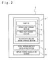
- Fig. 2 is a functional block diagram of the repair timing determination support apparatus 3.
- the repair timing determination support apparatus 3 includes a database 4, a total surplus/deficit calculation section 9, and a repair timing calculation section 10.
- This repair timing determination support apparatus 3 can be realized by a computer such as a PC or a server similarly to the remote monitoring apparatus 3-1 or the state monitoring apparatus.
- the total surplus/deficit calculation section 9 and the repair timing calculation section 10 can be realized by a CPU reading out and executing a program preliminary stored in a non-transitory storing medium such as a disk apparatus.
- a part ID 5 stores an identifier which specifies each part whose state is monitored by the monitoring apparatus 2.
- the repair cost storage section 6 represents the repair cost of each part specified by the part ID 5 in time-series.
- the work cost storage section 7 indicates the work cost for each part specified by the part ID 5 in time-series.
- the electricity selling income storage section 8 stores an estimated value of the electricity income which depends on the season.
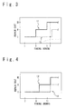
- Fig. 3 shows an example of the repair cost data stored in the repair cost storage section 6.
- the horizontal axis indicates the season.
- the vertical axis indicates the repair cost.
- Fig. 3 is an example of the repair cost data used in a case where the state monitoring apparatus detects a trouble corresponding to the level I in January.
- the repair cost curve 11 indicates the estimated repair cost after the level I state is detected in January in a case where the rated operation of the wind turbine 1 is continued.
- the repair cost curve 12 in lower right indicates the estimated repair cost after the level I trouble is detected in a case where the wind turbine 1 is operated in the safe mode in which the output is decreased by a predetermined percentage (for example, the output of 90%).
- repair cost curves 11, 12 are preliminary registered in the repair cost storage section 6 based on past experiences.
- Fig. 4 shows the estimated value of the repair cost when the level I state is detected in different seasons for a part same to the case of Fig. 3 .
- a wind turbine power generation apparatus has a tendency that the output becomes large in winter, so that the load on the part has a seasonal variation, which is heavy in winter. Therefore, the repair cost curve varies depending on the season.
- the repair cost curve 13 is estimated to be level II in October, and level III in December. If the level I state is detected in July, and the operation is continued with the output decreased to 90%, the level II state is estimated in December as represented by the repair cost curve 14.
- the repair cost curve 14 As shown in Fig. 3 and Fig.
- the repair cost storage section 6 stores the future estimation values of the repair costs such as shown in Fig. 3 and Fig. 4 for each part being a monitoring target of the monitoring apparatus 2.
- Fig. 5 shows an example of data stored in the electricity selling income storage section 8.
- the horizontal axis indicates the season, and the vertical axis indicates the income.
- the electricity selling income curve 15 indicates the estimated value of the electricity selling income under the rated operation.
- the output of the wind turbine 1 has a tendency to become large in winter, and the electricity selling income curve 15 reflects the variation depending on the season.
- the lower electricity selling income curve 16 indicates the estimated value of the electricity selling income when the wind turbine 1 is operated at the output of 90%.
- the estimated values of the electricity selling income determined based on the past actual performance or the like are preliminary stored in the electricity selling income storage section 8 for each wind turbine 1.
- Fig. 6 shows an example of data stored in the work cost storage section 7.
- the horizontal axis indicates the season, and the vertical axis indicates the cost of the work for repairing a part.
- the work cost curve 17 indicates the estimated value of the work cost.
- the work cost has a tendency to be larger in winter, and the work cost curve 17 reflects the variation depending on the season.
- the estimated values of the work cost being determined based on past experiences are preliminary stored in the work cost storage section 7.
- Fig. 7 is a flowchart of a repair timing determination support method according to the present embodiment.
- STEP S1 The monitoring apparatus 2, when an abnormality of a part is detected, transmits an abnormality detection signal which indicates the part ID specifying the part, the degree of the abnormality, and the type of the abnormality to the repair timing determination support apparatus 3.
- STEP S2 The repair timing determination support apparatus 3, when the abnormality detection signal is received, performs the initial setting of the repair timing.
- the time information such as the present year, month, and day is inputted by a built-in calendar function, or by an inputting operation to the input device by an operator.
- STEP S4 The setting of the power generation output is performed. For example, the rated operation (100% output) is set as the initial setting.
- the total surplus/deficit calculation section 9 performs the calculation of the repair cost. By this calculation, future repair costs are calculated at a predetermined time interval (for example, per month).
- the total surplus/deficit calculation section 9 refers to the database 4 and reads out the repair cost corresponding to the part ID 5 indicated by the abnormality detection signal from the repair cost storage section 6.
- a plurality of future timings (the total surplus/deficit estimation timings) which become targets of the estimated value calculation of the total surplus/deficit are set. For example, in a case where the set timing is January and the preliminary set calculation period is 6 months at STEP S2, the estimated value of the repair cost of each month from January to July is read out.
- the repair cost curve as shown in Fig. 3 is read out.
- the total surplus/deficit calculation section 9 calculates the electricity selling income. By this calculation, the future electricity selling income is calculated at a predetermined time interval (for example, every month).
- the total surplus/deficit calculation section 9 refers to the database 4 and reads out the estimated value of the electricity selling from the electricity selling income storage section 8. Also with respect to this electricity selling income, similarly to the repair cost, the estimated value for each month from January to July is read out, for example.
- the electricity selling income curve as shown in Fig. 5 is read out.
- the total surplus/deficit calculation section 9 further calculates the values of integral of the estimated values of the electricity selling income from the present time to each of the plurality of future estimation timings. By this calculation, in a case where the present time is January for example, the estimated values of the summation of the electricity selling incomes until respective months between February and July are obtained.
- the total surplus/deficit calculation section 9 performs a calculation of the work cost. By this calculation, the future work costs are calculated at a predetermined time interval (for example, per month).
- the total surplus/deficit calculation section 9 refers to the database 4 and reads out the work cost corresponding to the part ID 5 indicated by the abnormality detection signal from the work cost storage section 6. With respect to this work cost, similarly to the repair cost, the estimated value of each month from January to July, for example, is read out. As a result, with respect to the power generation output set at the STEP S4, the repair cost curve as shown in Fig. 4 is read out.
- the total surplus/deficit calculation section 9 calculates the estimation values of the future surplus/deficit in time-series by summing the respective estimated values in time-series of: the repair cost calculated at the STEPs S6 to S10; the values of integral of the electricity selling income; and the work cost, and outputs the calculation result as the total surplus/deficit curve.
- An operator can determine the repair timing of the part by referring to the estimated value of the total surplus/deficit in time-series corresponding to the power generation output set at the STEP S4.
- the repair timing calculation section 10 selects the estimated value at which the total surplus/deficit is best, namely, the surplus is the largest or the deficit is the smallest, among the estimated value of the total surplus/deficit in time-series, and extracts the timing corresponding to the selected estimated value. Consequently, a timing at which the repair cost and the work cost are relatively small, and the value of integral of the electricity selling income is relatively large, can be automatically selected.
- the repair timing calculation section 10 preliminary stores a plurality of candidates of the power generation output value (for example, 100%, 95%, 90%) of the wind turbine 1 after an abnormality is detected for a part of the wind turbine 1. As these candidates, it is enough to set at least a predetermined first output and a second output smaller than the first output.
- the repair timing calculation section 10 repeatedly executes the operation of the STEPs S6 to S16 with switching these output value candidates in turn (STEP S20).
- STEP S22 According to the above-described operation, the estimated value of the total surplus/deficit is obtained in time-series for each of the plurality of output value candidates.
- the repair timing calculation section 10 calculates and outputs the optimal (the total surplus/deficit is the best) power generation output and the repair timing. An operator determines the repair timing with taking the total surplus/deficit curve for each output value candidate, the optimal power generation output, and the optimal repair timing into consideration.
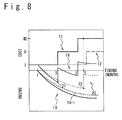
- the horizontal axis indicates the season.
- the upper half of the vertical axis indicates the repair cost.
- the lower half of the vertical axis indicates the summation (the value of integral) of the electricity selling income, and lower side indicates that the summation of the electricity selling income is larger.
- the total surplus/deficit curve 19, being the summation of the repair cost curve 11 and the electricity selling income curve 18 under the operation of 100% output of the wind turbine 1, indicates the total surplus/deficit in time-series at 100% output.
- the timing when the total surplus/deficit curve becomes the lowest value is the optimal timing of the total surplus/deficit.
- the repair timing 21 is indicated as the repair timing 21.
- the timing when the total surplus/deficit curve becomes the lowest value is the optimal timing of the total surplus/deficit.
- This timing is indicated as the repair timing 22.
- the repair timing 22 in the case of 90% output indicates the repair timing at which the total surplus/deficit is the optimal. Therefore, at the STEP S22 of Fig. 7 , the output of 90% is outputted as the optimal power generation output, and the repair timing 22 is outputted as the optimal repair timing.
- the total surplus/deficit calculation section 9 preliminary stores the implementation timings of the regular inspection.
- the processing of the STEPs S6 to S22 in Fig. 7 is performed for the period from the timing at which an abnormality of a part is detected to the timing of the regular inspection.
- the power generation output and the repair timing at which the total surplus/deficit becomes the optimal before the regular inspection is calculated.
- an operator determines whether the repair is to be performed at the calculated timing or the repair is to be performed at the regular inspection.
- the estimated values of the respective months which are continuous are calculated at a predetermined time interval (for example, every month).
- the estimated value may be calculated in a different manner. For example, by calculating the estimated values of the total surplus/deficit similar to the above-explained embodiment for a plurality of candidate timings, the optimal (the total surplus/deficit is best) power generation output and the repair timing can be calculated and outputted by referring to those estimated values.
- the plurality of candidate timings are not required to be continuous timings.
- the timings at which the work can be implemented may preliminary set as the first to n-th candidate timings (n is an integer of 2 or more), and the repair candidate timing may be calculated for each of the candidate timings.
Landscapes
- Engineering & Computer Science (AREA)
- Life Sciences & Earth Sciences (AREA)
- Sustainable Development (AREA)
- Sustainable Energy (AREA)
- Chemical & Material Sciences (AREA)
- Combustion & Propulsion (AREA)
- Mechanical Engineering (AREA)
- General Engineering & Computer Science (AREA)
- Wind Motors (AREA)
Abstract
Selecting work timing advantageous in cost with ensuring the soundness of the wind turbine generator is desired. The estimated value of the repair cost for a part of a wind turbine in time-series from an abnormality occurrence of the part is calculated in a case where the wind turbine operates at a first output and at a smaller second output. The estimated value of the electricity selling income of the wind turbine is calculated in cases of the first output and the second output. By referring to the repair cost estimated value and the electricity selling income estimated value, the total surplus/deficit from the abnormality occurrence to the repair of the part are calculated and outputted for each of the first and second outputs and for a plurality of repair timings. The output and repair timing at which the total surplus/deficit becomes optimal can be recognized.
Description
- The present invention relates to a technique for determining an appropriate repair timing of a wind turbine.
- When a trouble occurs in main parts for a wind turbine generator apparatus such as a bearing, a gearbox, an electric power generator and the like which are used in a wind turbine generator, it is required to stop the operation of the wind turbine generator apparatus until the work of replacement or repair of the part in trouble (a maintenance operation) is finished, which results in a problem that the electricity selling income is decreased.
- Further, in a case where the procedure of replacement or repair of a part is performed after the part became in trouble, the stop period of the wind turbine generator apparatus from the trouble to the recovery becomes longer, which results in a problem of further decreasing of the electricity selling income.
- For the purpose of solving the above problem, in
Patent Literature 1, a technique for a monitoring apparatus of wind turbine generator equipment is described. In the technique, the trouble of a part is predicted in advance, by determining whether or not the actual operation condition reaches the operation amount at which maintenance is required, based on: the actual operation history of the wind turbine generator equipment obtained by an operation state monitoring means; and the maintenance condition of the wind turbine equipment set in advance. By performing maintenance of the wind turbine generator apparatus in accordance with the estimation result, it is possible to reduce the stop period of the wind turbine generator apparatus. - Patent Literature 1: Japanese Patent Application Publication
JP2006-342766A - The wind condition varies depending on the seasons, and a strong wind tends to blow in winter. Therefore, in the wind turbine generator, the power generation amount has a tendency to be larger in winter, and be small in summer. As a result, if the wind turbine generator apparatus is stopped for maintenance in winter, the decrease amount of the electricity selling income is large. It is desired to reduce the maintenance which requires the stop of the wind turbine generator apparatus in winter, with ensuring the soundness of the wind turbine generator apparatus.
- Further, main parts of a wind turbine generator apparatus are installed mainly in high places, such as the nacelle mounted on the upper edge of the tower installed on the bedding, the rotor head mounted on the nacelle, and the like. Therefore, for implementing a work for repairing or replacing parts of the wind turbine generator apparatus, work in high places using crane equipment and the like is required.
- However, the wind turbine generator apparatus is an apparatus for transforming the wind power into the electric power, so that it is installed in a windy location. Further, as mentioned above, main parts of the wind turbine generator apparatus are installed in high places, which is exposed to wind.
- Therefore, there is a case where crane equipment and the like cannot be used caused by the influence of the wind. Depending on the season, there are date and hour when a work cannot be implemented, so that the work period becomes longer. In such a case, the period of stopping the wind turbine generator apparatus becomes longer.
- Further, when the work period of a wind turbine generator apparatus becomes longer, the cost for using crane equipment (namely, the rental fee of crane equipment) and the like increases, so that there is a case where the work cost is also increased.
- In particular, a strong wind tends to blow in winter. Therefore, when a work for maintenance is implemented in winter, the work period tends to be longer, and the work cost tends to increase. Also from the viewpoint of the work cost, the maintenance in winter is desired to be decreased.
- The present invention is invented from the above backgrounds, and an object of the present invention is to provide a work timing selection apparatus and a work timing selection method which enables the specification of an appropriate timing for implementing a work for a wind turbine generator apparatus.
- According to an aspect of the present invention, a repair timing determination support apparatus includes: a repair cost storage section configured to store a repair cost estimation value being a time-series estimation value of a cost for repairing a part of a wind turbine from an occurrence of a predetermined behavior of the part to a repair of the part for a case where the wind turbine operates at a first output and a case where the wind turbine operates at a second output lower than the first output; an electricity selling income storage section configured to store an electricity selling income estimation value being a time-series estimation value of an income from electricity selling of an electricity generated by the wind turbine for a case of the first output and a case of the second output; and a total surplus/deficit calculation section configured to calculate and output a total surplus/deficit from the occurrence of the predetermined behavior to the repair of the part for a case where the wind turbine operates at the first output and a case where the wind turbine operates at the second output at a plurality of repairing candidate timings by referring to the repair cost storage section and the electricity selling income storage section.
- According to another aspect of the present invention, a repair timing determination support method includes: a repair cost calculation step of calculating a repair cost estimation value being a time-series estimation value of a cost for repairing a part of a wind turbine from an occurrence of a predetermined behavior of the part to a repair of the part for a case where the wind turbine operates at a first output and a case where the wind turbine operates at a second output lower than the first output; an electricity selling income calculation step of calculating an electricity selling income estimation value being a time-series estimation value of an income from electricity selling of an electricity generated by the wind turbine for a case of the first output and a case of the second output; and a total surplus/deficit calculation step of calculating and outputting a total surplus/deficit from the occurrence of the predetermined behavior to the repair of the part for a case where the wind turbine operates at the first output and a case where the wind turbine operates at the second output at a plurality of repairing candidate timings by referring to the repair cost estimation value and the electricity selling income estimation value.
- According to the present invention, a repair timing determination support apparatus and a repair timing determination support method which enable the selection of work timing which is advantageous in cost with ensuring the soundness of the wind turbine generator apparatus.
- The above objects, other objects, effects, and characteristics of the present invention will become clearer by the description of embodiments with the accompany drawings, in which:
-
Fig. 1 shows a wind turbine, a remote monitoring apparatus, and a repair timing determination support apparatus; -
Fig. 2 is a functional block diagram of the repair timing determination support apparatus; -
Fig. 3 shows repair cost data; -
Fig. 4 shows repair cost data; -
Fig. 5 shows electricity selling income data; -
Fig. 6 shows work cost data; -
Fig. 7 is a flowchart of a repair timing determination support method; and -
Fig. 8 shows an example of a repair cost curve. - Some embodiments of the present invention will be explained below.
Fig. 1 shows awind turbine 1. Though thewind turbine 1 of the present embodiment is an upwind type, it may be a wind turbine of other types such as a downwind type wind turbine. A nacelle is mounted on a tower such that its rotation angle around a vertical line being its center axis can be controlled. A main shaft is mounted on the nacelle such that it is rotatable around a rotation axis, which is arranged approximately in the horizontal direction, as its center, and a rotor head is mounted on the main shaft. Around the rotation axis as the center, a plurality of blades are mounted at a predetermined pitch in the circumferential direction of the rotor head. The main shaft is rotated by receiving wind by the blades. The wind power generation is performed by increasing the rotation speed of the main shaft by a gearbox in the nacelle and by rotating the main shaft of an electricity generator. The produced electric power is subjected to the power conversion and the connection with the system to be sold. - A
monitoring apparatus 2 is mounted on thewind turbine 1. As themonitoring apparatus 2, for example, a vibration sensor which detects the vibration of the bearing of the gearbox, or a metal scan (a wear particle detecting apparatus) 60 of an oil lubrication apparatus which supplies oil to various bearings is mounted. The vibration sensor detects the vibration generated at a bearing, and the metal scan detected the amount of the wear particles in the oil lubrication apparatus. - The operation of the vibration sensor or the metal scan is controlled by the data collection apparatus 62 installed in each
wind turbine 1. - In particular, the data collection apparatus operates the vibration sensor or the metal scan at a predetermined interval (for example, one time in a day and about five minutes), and receives the input of the detection signal from the vibration sensor or the metal scan. When the detection signal is inputted, the data collection apparatus performs an analysis based on the detection signal, and transmits the result of the analysis to the remote monitoring apparatus 3-1 via a communication apparatus and a communication line (for example, the Internet) as a part state data. Here, the data collection apparatus and the communication apparatus are installed in the nacelle or in the tower, for example.
- The remote monitoring apparatus 3-1 includes a storage device such as an HDD (Hard Disk Drive) and stores a remote monitoring database in the storage device. In the remote monitoring database, the part state data transmitted from the data collection apparatus is stored in time-series and represented in a table format for every wind turbine power generation apparatus and for every main part.
- A state monitoring apparatus is connected to the remote monitoring apparatus 3-1. The state monitoring apparatus diagnoses the state of each main part mounted on the wind turbine power generator apparatus based on the contents of the remote monitoring database stored in the storage device of the remote monitoring apparatus 3-1, and stores the state monitoring database which represents the diagnosis results for every main part in the storage device. The diagnosis of the state of a main part means that estimating the timing at which a trouble occurs for the main part, or outputting the abnormality level suggested by the predetermined detected behavior, based on the time variation of the detection signal outputted by the state detection apparatus (for example, a vibration sensor or a metal scan) which detects the state of the main parts mounted on the wind turbine power generation apparatus.
- The state monitoring apparatus further diagnoses the state of main parts as follows. It is assumed that, for a certain part, the relation between the state detected by the
monitoring apparatus 2 and the required maintenance level is determined. For example, it is assumed to be predetermined that the state is normal at the level 0, a slight maintenance is required at the level I, a medium level maintenance is required at the level II, and a part replacement is required at the level III. The state monitoring apparatus determines the maintenance level for each part based on the detection signal of themonitoring apparatus 2 in accordance with a predetermined standard. The repair cost of each part is determined by its maintenance level. - A repair timing
determination support apparatus 3 is connected to the remote monitoring apparatus 3-1. When an abnormality occurs for a part of thewind turbine 1, there is a case that an instant repair is not required and it can be further operated in a certain period. If a trouble is detected in winter, since the electricity selling income is large in winter, stopping the operation for repairing the part is not preferred. In such a case, the repair cost may be reduced by decreasing the output of thewind turbine 1 for reducing the load on the part and postponing the repair of the part which requires the stopping of thewind turbine 1 to the timing when the electricity selling income is relatively small. The repair timingdetermination support apparatus 3 performs the calculation for determining the repair timing at which the cost becomes low. -
Fig. 2 is a functional block diagram of the repair timingdetermination support apparatus 3. The repair timingdetermination support apparatus 3 includes adatabase 4, a total surplus/deficit calculation section 9, and a repairtiming calculation section 10. This repair timingdetermination support apparatus 3 can be realized by a computer such as a PC or a server similarly to the remote monitoring apparatus 3-1 or the state monitoring apparatus. The total surplus/deficit calculation section 9 and the repairtiming calculation section 10 can be realized by a CPU reading out and executing a program preliminary stored in a non-transitory storing medium such as a disk apparatus. - In the
database 4, apart ID 5, a repaircost storage section 6, a workcost storage section 7, and an electricity sellingincome storage section 8 are stored. Thepart ID 5 stores an identifier which specifies each part whose state is monitored by themonitoring apparatus 2. The repaircost storage section 6 represents the repair cost of each part specified by thepart ID 5 in time-series. The workcost storage section 7 indicates the work cost for each part specified by thepart ID 5 in time-series. The electricity sellingincome storage section 8 stores an estimated value of the electricity income which depends on the season. - Next, the data stored in the repair cost storage section is explained in detail.
Fig. 3 shows an example of the repair cost data stored in the repaircost storage section 6. The horizontal axis indicates the season. The vertical axis indicates the repair cost.Fig. 3 is an example of the repair cost data used in a case where the state monitoring apparatus detects a trouble corresponding to the level I in January. - The
repair cost curve 11 indicates the estimated repair cost after the level I state is detected in January in a case where the rated operation of thewind turbine 1 is continued. Therepair cost curve 12 in lower right indicates the estimated repair cost after the level I trouble is detected in a case where thewind turbine 1 is operated in the safe mode in which the output is decreased by a predetermined percentage (for example, the output of 90%). - In a case where the rated operation is continued without implementing a maintenance work for the part after the level I state is detected in January, In
Fig. 3 , it is estimated that the state of the part becomes level II in March, and level III in May. Therewith, the repair cost increases in March, and further increases in May. On the other hand, in a case where the output is decreased to 90%, the load on a bearing, a gear and the like is reduced, so that the deterioration of the part is relaxed. In therepair cost curve 13 inFig. 3 , in a case where the output is decreased to 90% after the level I state is detected in January, the state is estimated to be level II in the period near after May. Therefore, if the repair is implemented at a timing T just after May, the repair cost can be suppressed by (the repair cost for level III) - (the repair cost for level I). These repair costcurves cost storage section 6 based on past experiences. -
Fig. 4 shows the estimated value of the repair cost when the level I state is detected in different seasons for a part same to the case ofFig. 3 . A wind turbine power generation apparatus has a tendency that the output becomes large in winter, so that the load on the part has a seasonal variation, which is heavy in winter. Therefore, the repair cost curve varies depending on the season. In the example ofFig. 4 , in a case where the level I state is detected in July and the rated operation is continued, therepair cost curve 13 is estimated to be level II in October, and level III in December. If the level I state is detected in July, and the operation is continued with the output decreased to 90%, the level II state is estimated in December as represented by the repair cost curve 14. As shown inFig. 3 and Fig. 4 , it is preferable to preliminary register two or more repair cost curves whose trouble occurrence timing is different from each other in the repaircost storage section 6. The repaircost storage section 6 stores the future estimation values of the repair costs such as shown inFig. 3 and Fig. 4 for each part being a monitoring target of themonitoring apparatus 2. -
Fig. 5 shows an example of data stored in the electricity sellingincome storage section 8. The horizontal axis indicates the season, and the vertical axis indicates the income. The electricityselling income curve 15 indicates the estimated value of the electricity selling income under the rated operation. The output of thewind turbine 1 has a tendency to become large in winter, and the electricityselling income curve 15 reflects the variation depending on the season. The lower electricityselling income curve 16 indicates the estimated value of the electricity selling income when thewind turbine 1 is operated at the output of 90%. The estimated values of the electricity selling income determined based on the past actual performance or the like are preliminary stored in the electricity sellingincome storage section 8 for eachwind turbine 1. -
Fig. 6 shows an example of data stored in the workcost storage section 7. The horizontal axis indicates the season, and the vertical axis indicates the cost of the work for repairing a part. Thework cost curve 17 indicates the estimated value of the work cost. The work cost has a tendency to be larger in winter, and thework cost curve 17 reflects the variation depending on the season. The estimated values of the work cost being determined based on past experiences are preliminary stored in the workcost storage section 7. - Next, an operation of the repair timing
determination support apparatus 3 having the above-explained structure is explained.Fig. 7 is a flowchart of a repair timing determination support method according to the present embodiment. - STEP S1: The
monitoring apparatus 2, when an abnormality of a part is detected, transmits an abnormality detection signal which indicates the part ID specifying the part, the degree of the abnormality, and the type of the abnormality to the repair timingdetermination support apparatus 3. - STEP S2: The repair timing
determination support apparatus 3, when the abnormality detection signal is received, performs the initial setting of the repair timing. The time information such as the present year, month, and day is inputted by a built-in calendar function, or by an inputting operation to the input device by an operator. - STEP S4: The setting of the power generation output is performed. For example, the rated operation (100% output) is set as the initial setting.
- STEP S6: The total surplus/
deficit calculation section 9 performs the calculation of the repair cost. By this calculation, future repair costs are calculated at a predetermined time interval (for example, per month). The total surplus/deficit calculation section 9 refers to thedatabase 4 and reads out the repair cost corresponding to thepart ID 5 indicated by the abnormality detection signal from the repaircost storage section 6. At this stage, a plurality of future timings (the total surplus/deficit estimation timings) which become targets of the estimated value calculation of the total surplus/deficit are set. For example, in a case where the set timing is January and the preliminary set calculation period is 6 months at STEP S2, the estimated value of the repair cost of each month from January to July is read out. As a result, with regard to the power generation output set at the STEP S4, the repair cost curve as shown inFig. 3 is read out. - STEP S8: The total surplus/
deficit calculation section 9 calculates the electricity selling income. By this calculation, the future electricity selling income is calculated at a predetermined time interval (for example, every month). The total surplus/deficit calculation section 9 refers to thedatabase 4 and reads out the estimated value of the electricity selling from the electricity sellingincome storage section 8. Also with respect to this electricity selling income, similarly to the repair cost, the estimated value for each month from January to July is read out, for example. As a result, with respect to the power generation output set at the STEP S4, the electricity selling income curve as shown inFig. 5 is read out. The total surplus/deficit calculation section 9 further calculates the values of integral of the estimated values of the electricity selling income from the present time to each of the plurality of future estimation timings. By this calculation, in a case where the present time is January for example, the estimated values of the summation of the electricity selling incomes until respective months between February and July are obtained. - STEP S10: The total surplus/
deficit calculation section 9 performs a calculation of the work cost. By this calculation, the future work costs are calculated at a predetermined time interval (for example, per month). The total surplus/deficit calculation section 9 refers to thedatabase 4 and reads out the work cost corresponding to thepart ID 5 indicated by the abnormality detection signal from the workcost storage section 6. With respect to this work cost, similarly to the repair cost, the estimated value of each month from January to July, for example, is read out. As a result, with respect to the power generation output set at the STEP S4, the repair cost curve as shown inFig. 4 is read out. - STEP S14: The total surplus/
deficit calculation section 9 calculates the estimation values of the future surplus/deficit in time-series by summing the respective estimated values in time-series of: the repair cost calculated at the STEPs S6 to S10; the values of integral of the electricity selling income; and the work cost, and outputs the calculation result as the total surplus/deficit curve. An operator can determine the repair timing of the part by referring to the estimated value of the total surplus/deficit in time-series corresponding to the power generation output set at the STEP S4. - STEP S16: The repair
timing calculation section 10 selects the estimated value at which the total surplus/deficit is best, namely, the surplus is the largest or the deficit is the smallest, among the estimated value of the total surplus/deficit in time-series, and extracts the timing corresponding to the selected estimated value. Consequently, a timing at which the repair cost and the work cost are relatively small, and the value of integral of the electricity selling income is relatively large, can be automatically selected. - STEP S18: The repair
timing calculation section 10 preliminary stores a plurality of candidates of the power generation output value (for example, 100%, 95%, 90%) of thewind turbine 1 after an abnormality is detected for a part of thewind turbine 1. As these candidates, it is enough to set at least a predetermined first output and a second output smaller than the first output. The repairtiming calculation section 10 repeatedly executes the operation of the STEPs S6 to S16 with switching these output value candidates in turn (STEP S20). - STEP S22: According to the above-described operation, the estimated value of the total surplus/deficit is obtained in time-series for each of the plurality of output value candidates. The repair
timing calculation section 10 calculates and outputs the optimal (the total surplus/deficit is the best) power generation output and the repair timing. An operator determines the repair timing with taking the total surplus/deficit curve for each output value candidate, the optimal power generation output, and the optimal repair timing into consideration. - With reference to
Fig. 8 , an example of the repair timing decision is explained. In the example ofFig. 8 , the work cost is eliminated for simplifying the explanation. The horizontal axis indicates the season. The upper half of the vertical axis indicates the repair cost. The lower half of the vertical axis indicates the summation (the value of integral) of the electricity selling income, and lower side indicates that the summation of the electricity selling income is larger. The total surplus/deficit curve 19, being the summation of therepair cost curve 11 and the electricityselling income curve 18 under the operation of 100% output of thewind turbine 1, indicates the total surplus/deficit in time-series at 100% output. The timing when the total surplus/deficit curve becomes the lowest value is the optimal timing of the total surplus/deficit. This timing is indicated as therepair timing 21. The total surplus/deficit curve 20, being the summation of therepair cost curve 12 and the electricity selling income curve 18-1 under the operation of 90% output of thewind turbine 1, indicates the total surplus/deficit in time-series at 90% output. The timing when the total surplus/deficit curve becomes the lowest value is the optimal timing of the total surplus/deficit. This timing is indicated as therepair timing 22. In the example shown inFig. 8 , therepair timing 22 in the case of 90% output indicates the repair timing at which the total surplus/deficit is the optimal. Therefore, at the STEP S22 ofFig. 7 , the output of 90% is outputted as the optimal power generation output, and therepair timing 22 is outputted as the optimal repair timing. - In a case where a regular inspection of the
wind turbine 1 is performed at timing relatively near the timing when themonitoring apparatus 2 detects an abnormality of a part, it is preferred that the repair of the part is performed at the same time with the regular inspection. Therefore, the total surplus/deficit calculation section 9 preliminary stores the implementation timings of the regular inspection. In such a case, the processing of the STEPs S6 to S22 inFig. 7 is performed for the period from the timing at which an abnormality of a part is detected to the timing of the regular inspection. By this processing, the power generation output and the repair timing at which the total surplus/deficit becomes the optimal before the regular inspection is calculated. By referring to the output, an operator determines whether the repair is to be performed at the calculated timing or the repair is to be performed at the regular inspection. - In the above explanation, the estimated values of the respective months which are continuous are calculated at a predetermined time interval (for example, every month). However, the estimated value may be calculated in a different manner. For example, by calculating the estimated values of the total surplus/deficit similar to the above-explained embodiment for a plurality of candidate timings, the optimal (the total surplus/deficit is best) power generation output and the repair timing can be calculated and outputted by referring to those estimated values. The plurality of candidate timings are not required to be continuous timings. For example, in a case where the timings at which the work can be implemented are limited for some reasons, the timings at which the work can be implemented may preliminary set as the first to n-th candidate timings (n is an integer of 2 or more), and the repair candidate timing may be calculated for each of the candidate timings.
- It is easily understood for those skilled in the art that the above-explained embodiments can be implemented by any combination thereof in an extent that no contradiction occurs.
- The present application claims a priority based on Japanese Patent Application No.
2011-144443
Claims (6)
- A repair timing determination support apparatus comprising:a repair cost storage section configured to store a repair cost estimation value being a time-series estimation value of a cost for repairing a part of a wind turbine from an occurrence of a predetermined behavior of the part to a repair of the part for a case where the wind turbine operates at a first output and a case where the wind turbine operates at a second output lower than the first output;an electricity selling income storage section configured to store an electricity selling income estimation value being a time-series estimation value of an income from electricity selling of an electricity generated by the wind turbine for a case of the first output and a case of the second output; anda total surplus/deficit calculation section configured to calculate and output a total surplus/deficit from the occurrence of the predetermined behavior to the repair of the part for a case where the wind turbine operates at the first output and a case where the wind turbine operates at the second output at a plurality of repairing candidate timings by referring to the repair cost storage section and the electricity selling income storage section.
- The repair timing determination support apparatus according to claim 1, wherein the electricity selling income estimation value depends on a seasonal variation.
- The repair timing determination support apparatus according to claim 1 or 2, further comprising:a work cost storage section which stores a work cost estimation value being a time-series estimation value of a work cost for the repair of the part,wherein the total surplus/deficit calculation section is configured to calculate the total surplus/deficit by including the work cost by referring to the work cost storage section.
- The repair timing determination support apparatus according to claim 3, wherein the work cost estimation value depends on a seasonal variation.
- The repair timing determination support apparatus according to any of claims 1 to 4, further comprising:a repair timing calculation section configured to calculate and output a timing at which the total surplus/deficit calculated by the total surplus/deficit calculation section becomes an optimal value as an exchange timing of the part.
- A repair timing determination support method comprising:a repair cost calculation step of calculating a repair cost estimation value being a time-series estimation value of a cost for repairing a part of a wind turbine from an occurrence of a predetermined behavior of the part to a repair of the part for a case where the wind turbine operates at a first output and a case where the wind turbine operates at a second output lower than the first output;an electricity selling income calculation step of calculating an electricity selling income estimation value being a time-series estimation value of an income from electricity selling of an electricity generated by the wind turbine for a case of the first output and a case of the second output; anda total surplus/deficit calculation step of calculating and outputting a total surplus/deficit from the occurrence of the predetermined behavior to the repair of the part for a case where the wind turbine operates at the first output and a case where the wind turbine operates at the second output at a plurality of repairing candidate timings by referring to the repair cost estimation value and the electricity selling income estimation value.
Applications Claiming Priority (2)
| Application Number | Priority Date | Filing Date | Title |
|---|---|---|---|
| JP2011144443A JP2013011232A (en) | 2011-06-29 | 2011-06-29 | Windmill repair timing determination support device and repair timing determination support method |
| PCT/JP2012/066509 WO2013002316A1 (en) | 2011-06-29 | 2012-06-28 | Windmill repair timing determination support device and repair timing determination support method |
Publications (1)
| Publication Number | Publication Date |
|---|---|
| EP2728177A1 true EP2728177A1 (en) | 2014-05-07 |
Family
ID=47424202
Family Applications (1)
| Application Number | Title | Priority Date | Filing Date |
|---|---|---|---|
| EP12804480.7A Withdrawn EP2728177A1 (en) | 2011-06-29 | 2012-06-28 | Windmill repair timing determination support device and repair timing determination support method |
Country Status (3)
| Country | Link |
|---|---|
| EP (1) | EP2728177A1 (en) |
| JP (1) | JP2013011232A (en) |
| WO (1) | WO2013002316A1 (en) |
Families Citing this family (5)
| Publication number | Priority date | Publication date | Assignee | Title |
|---|---|---|---|---|
| KR20160017681A (en) | 2014-07-31 | 2016-02-17 | 두산중공업 주식회사 | System and method for managing wind plant |
| CN109751196B (en) * | 2017-11-03 | 2020-05-29 | 北京金风科创风电设备有限公司 | Wind generating set identification method and device |
| JP7433052B2 (en) * | 2020-01-06 | 2024-02-19 | Ntn株式会社 | Condition monitoring device and wind power generator equipped with condition monitoring device |
| KR102569043B1 (en) * | 2023-03-06 | 2023-08-24 | 주식회사 에이투엠 | Dismantling and recycling management system for wind power generation facilities |
| JP2025103490A (en) * | 2023-12-27 | 2025-07-09 | Ntn株式会社 | Diagnostic device and diagnostic method |
Family Cites Families (7)
| Publication number | Priority date | Publication date | Assignee | Title |
|---|---|---|---|---|
| JP3801063B2 (en) * | 2001-02-27 | 2006-07-26 | 株式会社日立製作所 | Power generation facility operation and maintenance plan support system |
| JP2002349413A (en) * | 2001-05-24 | 2002-12-04 | Mitsubishi Electric Corp | Wind power generation system |
| JP4449597B2 (en) * | 2004-06-25 | 2010-04-14 | 東京電力株式会社 | Information processing method and apparatus for evaluating the effect of investment in power generation facilities |
| JP2006342766A (en) | 2005-06-10 | 2006-12-21 | Mitsubishi Electric Corp | Wind power generation equipment monitoring device |
| JP4699344B2 (en) * | 2005-12-07 | 2011-06-08 | 三菱重工業株式会社 | Equipment maintenance planning method for plant equipment |
| JP5270963B2 (en) * | 2008-05-29 | 2013-08-21 | 株式会社日立製作所 | Wind power generation facility remote monitoring device, wind power generation remote management method, and wind power generation remote management program |
| JP5388713B2 (en) * | 2008-06-18 | 2014-01-15 | 一般財団法人電力中央研究所 | Power distribution facility maintenance support device, power distribution facility maintenance support method, and power distribution facility maintenance support program |
-
2011
- 2011-06-29 JP JP2011144443A patent/JP2013011232A/en not_active Withdrawn
-
2012
- 2012-06-28 EP EP12804480.7A patent/EP2728177A1/en not_active Withdrawn
- 2012-06-28 WO PCT/JP2012/066509 patent/WO2013002316A1/en not_active Ceased
Non-Patent Citations (1)
| Title |
|---|
| See references of WO2013002316A1 * |
Also Published As
| Publication number | Publication date |
|---|---|
| WO2013002316A1 (en) | 2013-01-03 |
| JP2013011232A (en) | 2013-01-17 |
Similar Documents
| Publication | Publication Date | Title |
|---|---|---|
| US10600036B2 (en) | Wind power plant management system and method thereof | |
| Bangalore et al. | Analysis of SCADA data for early fault detection, with application to the maintenance management of wind turbines | |
| Yang et al. | Wind turbine condition monitoring: technical and commercial challenges | |
| Santelo et al. | Wind turbine failures review and trends | |
| US20120203704A1 (en) | Servicing-timing selecting apparatus and servicing-timing selecting method | |
| Andrawus | Maintenance optimisation for wind turbines. | |
| JP6783110B2 (en) | Predictive diagnostic device and power generation device control system with it | |
| KR20160073945A (en) | System and method for managing wind plant | |
| EP3608538A1 (en) | Model-based repowering solutions for wind turbines | |
| US20200040873A1 (en) | Method for Operating a Wind Turbine and a Wind Turbine System | |
| Pinar Pérez et al. | Economic viability analytics for wind energy maintenance management | |
| EP3796016B1 (en) | System and method for detecting battery faults in a pitch system of a wind turbine | |
| CN117738851A (en) | Wind turbine generator system fault diagnosis method based on dynamic load | |
| WO2013002316A1 (en) | Windmill repair timing determination support device and repair timing determination support method | |
| CN119103012A (en) | A health status prediction method for high-end equipment | |
| Puglia | Life cycle cost analysis on wind turbines | |
| Dinh et al. | Implementation of digital twin-assisted condition monitoring and fault diagnosis for wind turbines | |
| EP3855019A1 (en) | System and method for operating a wind turbine | |
| Bangalore | Load and risk based maintenance management of wind turbines | |
| Barberá et al. | State of the art of maintenance applied to wind turbines | |
| Zhang et al. | Probability warning for wind turbine gearbox incipient faults based on SCADA data | |
| Ambühl et al. | On different maintenance strategies for casted components of offshore wind turbines | |
| Ferrari et al. | Statistical analysis of component failures: A 16 year survey on more than 550 wind turbines | |
| Rademakers et al. | Operation and maintenance of offshore wind energy systems | |
| Zappalá | Advanced algorithms for automatic wind turbine condition monitoring |
Legal Events
| Date | Code | Title | Description |
|---|---|---|---|
| PUAI | Public reference made under article 153(3) epc to a published international application that has entered the european phase |
Free format text: ORIGINAL CODE: 0009012 |
|
| 17P | Request for examination filed |
Effective date: 20131129 |
|
| AK | Designated contracting states |
Kind code of ref document: A1 Designated state(s): AL AT BE BG CH CY CZ DE DK EE ES FI FR GB GR HR HU IE IS IT LI LT LU LV MC MK MT NL NO PL PT RO RS SE SI SK SM TR |
|
| DAX | Request for extension of the european patent (deleted) | ||
| STAA | Information on the status of an ep patent application or granted ep patent |
Free format text: STATUS: THE APPLICATION HAS BEEN WITHDRAWN |
|
| 18W | Application withdrawn |
Effective date: 20141006 |