EP2728168A2 - Wind turbine blades with tension fabric skin structure - Google Patents
Wind turbine blades with tension fabric skin structure Download PDFInfo
- Publication number
- EP2728168A2 EP2728168A2 EP13190272.8A EP13190272A EP2728168A2 EP 2728168 A2 EP2728168 A2 EP 2728168A2 EP 13190272 A EP13190272 A EP 13190272A EP 2728168 A2 EP2728168 A2 EP 2728168A2
- Authority
- EP
- European Patent Office
- Prior art keywords
- wise members
- fabric
- members
- span
- wind blade
- Prior art date
- Legal status (The legal status is an assumption and is not a legal conclusion. Google has not performed a legal analysis and makes no representation as to the accuracy of the status listed.)
- Granted
Links
Images



Classifications
-
- F—MECHANICAL ENGINEERING; LIGHTING; HEATING; WEAPONS; BLASTING
- F03—MACHINES OR ENGINES FOR LIQUIDS; WIND, SPRING, OR WEIGHT MOTORS; PRODUCING MECHANICAL POWER OR A REACTIVE PROPULSIVE THRUST, NOT OTHERWISE PROVIDED FOR
- F03D—WIND MOTORS
- F03D1/00—Wind motors with rotation axis substantially parallel to the air flow entering the rotor
- F03D1/06—Rotors
- F03D1/065—Rotors characterised by their construction elements
- F03D1/0675—Rotors characterised by their construction elements of the blades
-
- F—MECHANICAL ENGINEERING; LIGHTING; HEATING; WEAPONS; BLASTING
- F05—INDEXING SCHEMES RELATING TO ENGINES OR PUMPS IN VARIOUS SUBCLASSES OF CLASSES F01-F04
- F05B—INDEXING SCHEME RELATING TO WIND, SPRING, WEIGHT, INERTIA OR LIKE MOTORS, TO MACHINES OR ENGINES FOR LIQUIDS COVERED BY SUBCLASSES F03B, F03D AND F03G
- F05B2280/00—Materials; Properties thereof
- F05B2280/40—Organic materials
- F05B2280/4003—Synthetic polymers, e.g. plastics
-
- F—MECHANICAL ENGINEERING; LIGHTING; HEATING; WEAPONS; BLASTING
- F05—INDEXING SCHEMES RELATING TO ENGINES OR PUMPS IN VARIOUS SUBCLASSES OF CLASSES F01-F04
- F05B—INDEXING SCHEME RELATING TO WIND, SPRING, WEIGHT, INERTIA OR LIKE MOTORS, TO MACHINES OR ENGINES FOR LIQUIDS COVERED BY SUBCLASSES F03B, F03D AND F03G
- F05B2280/00—Materials; Properties thereof
- F05B2280/50—Intrinsic material properties or characteristics
- F05B2280/5001—Elasticity
-
- F—MECHANICAL ENGINEERING; LIGHTING; HEATING; WEAPONS; BLASTING
- F05—INDEXING SCHEMES RELATING TO ENGINES OR PUMPS IN VARIOUS SUBCLASSES OF CLASSES F01-F04
- F05B—INDEXING SCHEME RELATING TO WIND, SPRING, WEIGHT, INERTIA OR LIKE MOTORS, TO MACHINES OR ENGINES FOR LIQUIDS COVERED BY SUBCLASSES F03B, F03D AND F03G
- F05B2280/00—Materials; Properties thereof
- F05B2280/60—Properties or characteristics given to material by treatment or manufacturing
- F05B2280/6001—Fabrics
- F05B2280/6002—Woven fabrics
-
- F—MECHANICAL ENGINEERING; LIGHTING; HEATING; WEAPONS; BLASTING
- F05—INDEXING SCHEMES RELATING TO ENGINES OR PUMPS IN VARIOUS SUBCLASSES OF CLASSES F01-F04
- F05B—INDEXING SCHEME RELATING TO WIND, SPRING, WEIGHT, INERTIA OR LIKE MOTORS, TO MACHINES OR ENGINES FOR LIQUIDS COVERED BY SUBCLASSES F03B, F03D AND F03G
- F05B2280/00—Materials; Properties thereof
- F05B2280/60—Properties or characteristics given to material by treatment or manufacturing
- F05B2280/6013—Fibres
-
- Y—GENERAL TAGGING OF NEW TECHNOLOGICAL DEVELOPMENTS; GENERAL TAGGING OF CROSS-SECTIONAL TECHNOLOGIES SPANNING OVER SEVERAL SECTIONS OF THE IPC; TECHNICAL SUBJECTS COVERED BY FORMER USPC CROSS-REFERENCE ART COLLECTIONS [XRACs] AND DIGESTS
- Y02—TECHNOLOGIES OR APPLICATIONS FOR MITIGATION OR ADAPTATION AGAINST CLIMATE CHANGE
- Y02E—REDUCTION OF GREENHOUSE GAS [GHG] EMISSIONS, RELATED TO ENERGY GENERATION, TRANSMISSION OR DISTRIBUTION
- Y02E10/00—Energy generation through renewable energy sources
- Y02E10/70—Wind energy
- Y02E10/72—Wind turbines with rotation axis in wind direction
-
- Y—GENERAL TAGGING OF NEW TECHNOLOGICAL DEVELOPMENTS; GENERAL TAGGING OF CROSS-SECTIONAL TECHNOLOGIES SPANNING OVER SEVERAL SECTIONS OF THE IPC; TECHNICAL SUBJECTS COVERED BY FORMER USPC CROSS-REFERENCE ART COLLECTIONS [XRACs] AND DIGESTS
- Y10—TECHNICAL SUBJECTS COVERED BY FORMER USPC
- Y10T—TECHNICAL SUBJECTS COVERED BY FORMER US CLASSIFICATION
- Y10T29/00—Metal working
- Y10T29/49—Method of mechanical manufacture
- Y10T29/49316—Impeller making
- Y10T29/49336—Blade making
Definitions
- the present application relates generally to wind turbines and more particularly relates to wind turbine rotor blades having a tension fabric skin structure.
- Wind turbines generate electricity by effectively harnessing energy in the wind via a rotor having a set of rotor blades that turns a gearbox and generator, thereby converting mechanical energy to electrical energy that may be deployed to a utility grid.
- the construction of a modem rotor blade generally includes skin or shell components, span-wise extending spar caps, and one or more shear webs.
- Present technology uses several molds to fabricate the various pieces of the blade that are bonded together in large resin-infused molds. Such finished blades are relatively heavy and includes a hardened shell encasing the molded hardened shear webs or spar caps.
- a wind blade in accordance with an embodiment of the invention, includes a self-supporting structural framework, having multiple chord-wise members and one or more span-wise members. Each of the multiple chord-wise members and the one or more span-wise members have an aerodynamic contour.
- the wind blade also comprises a fabric skin located over the self-supporting structural framework in a tensioned state to generate an aerodynamic surface, wherein the fabric skin is attached via multiple tensioning members to both the chord wise members and span wise members.
- a method of manufacturing a wind blade includes forming a self-supporting structural framework, having multiple chord-wise members and one or more span-wise members, wherein each of the plurality of the chord-wise members and the one or more span-wise members have an aerodynamic contour.
- the method also includes configuring a fabric skin having multiple fabric strips over the self-supporting structural framework in a tensioned state to generate an aerodynamic outer surface by attaching the fabric skin to both the chord wise members and the one or more span wise members.
- a wind turbine in accordance with an embodiment of the invention, includes multiple wind blades, wherein each of the blades comprises a self-supporting structural framework, having multiple chord-wise members and one or more span-wise members. Each of the multiple chord-wise members and the one or more span-wise members have an aerodynamic contour.
- the wind turbine also includes a fabric skin located over the self-supporting structural framework in a tensioned state to generate an aerodynamic surface, wherein the fabric skin is attached via multiple tensioning members to both the chord wise members and span wise members.
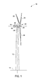
- FIG. 1 is a perspective view of an exemplary wind turbine 10 in accordance with an embodiment of the present invention.
- the wind turbine 10 is a horizontal-axis wind turbine.
- the wind turbine 10 may be a vertical-axis wind turbine.
- the wind turbine 10 includes a tower 12 that extends from a support surface 14, a nacelle 16 mounted on the tower 12, a generator 18 positioned within the nacelle 16, a gearbox 20 coupled to the generator 18, and a rotor 22 that is rotatably coupled to the gearbox 20 with a rotor shaft 24.
- the rotor 22 includes a rotatable hub 26 and at least one rotor blade 28 coupled to and extending outward from the rotatable hub 26.
- FIG. 2 is a perspective view of a rotor blade 28 in accordance with an embodiment of the present invention.
- the rotor blade 28 includes a pressure side 32 and a suction side 34 extending between a leading edge 36 and a trailing edge 38, and may extend from a blade tip 42 to a blade root 44.
- the exterior surfaces may be generally aerodynamic surfaces having generally aerodynamic contours, as is generally known in the art.
- the rotor blade 28 further includes a fabric skin with multiple individual fabric sections 50 between the blade tip 42 and the blade root 44.
- Each of fabric sections 50 may be uniquely configured so that the multiple fabric sections 50 define a complete rotor blade 28 having a designed aerodynamic profile.
- each of the fabric sections 50 may have an aerodynamic profile that corresponds to the aerodynamic profile of adjacent section 50.
- the aerodynamic profiles of the fabric sections 50 may form a continuous aerodynamic profile of the rotor blade 28.
- the rotor blade 28 may further define a chord 52 and a span 54 extending in chord-wise and span-wise directions, respectively. As shown, the chord 52 may vary throughout the span 54 of the rotor blade 28.
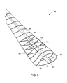
- FIG. 3 illustrates further details of the rotor blade 28 in accordance with an embodiment of the present invention.
- the rotor blade 28 includes a self-supporting structural framework 60 that extents span-wise from the blade root 44 (shown in FIG. 2 ) towards the blade tip 42 (as shown in FIG. 2 ).
- the self-supporting structural framework 60 includes multiple chord-wise members and one or more span-wise members. Each of the multiple chord-wise members and the one or more span-wise members have an aerodynamic contour.
- the one or more span-wise members include an internal support structure 62, a leading edge reinforcement member 64 and a trailing edge reinforcement member 66.
- the internal support structure 62 is formed from a single shear web 68 and associated spar caps 70 that run span-wise along the pressure side 32 and suction side 34 of the blade 28.
- This internal support structure 62 provides for rigidity and dimensional stability to the wind blade 28.
- the internal support structure 62 includes a cross-section geometry with an I-beam shape or hat shape, C-shape, U-shape, T-shape, or combinations thereof.
- the multiple chord-wise members include multiple airfoil shaped reinforcing ribs 72 arranged in chord-wise orientation. The ribs 72 are attached to the leading edge reinforcement member 64 on one side, the trailing edge reinforcement member 66 on the other side and spaced along the internal support structure 62.
- the multiple chord wise members include multiple airfoil shaped solid or hollow hoops.
- the airfoil shaped reinforcing ribs 72 are connected via multiple truss elements 80 that provide additional strength to the overall self-supporting structural framework 60 of the wind blade 28.
- FIG. 3 shows the rotor blade 28 having the fabric skin with multiple individual fabric sections 50 located over the self-supporting structural framework in a tensioned state to generate an aerodynamic surface.
- the fabric skin is attached via multiple tensioning members to both the chord wise members and span wise members.
- the fabric skin also includes multiple fabric strips 74 attached to the multiple chord-wise members and/or the one or more span-wise members via the tensioning members.
- Non-limiting examples of materials of the tensioning members include extruded metal, roll formed metal and molded or pultruded polymer matrix composites.
- each of the fabric strips 74 includes a fabric dimension smaller than a dimension of each of the chord-wise members and/or the one or more span-wise members such that the multiple fabric strips 74 are in tension when attached with the chord-wise members and/or the one or more span-wise members.
- the fabric skin of the wind blade 28 includes reinforcing fibers and stretchable matrix materials.
- the stretchable matrix material of the fabric skin has an elongation of greater than 10%.
- the stretchable matrix materials include elastomers, PTFE, ETFE, PU, PVC, silicone, nitrile rubber, EPDM rubber, natural rubber, thermoplastic elastomers, thermoplastic vulcanizates, and combinations thereof.
- the natural rubber may be unsaturated rubbers and saturated rubbers, wherein non-limiting examples of the unsaturated rubbers comprises Natural polyisoprene: cis-1,4-polyisoprene natural rubber (NR) and trans-1,4-polyisoprene gutta-percha, Synthetic polyisoprene (IR for Isoprene Rubber), Polybutadiene (BR for Butadiene Rubber), Chloroprene rubber (CR), polychloroprene, Neoprene, Baypren; Butyl rubber (copolymer of isobutylene and isoprene, IIR), Halogenated butyl rubbers (chloro butyl rubber: CIIR; bromo butyl rubber: BIIR), Styrene-butadiene Rubber (copolymer of styrene and butadiene, SBR), Nitrile rubber (copolymer of butadiene and acrylonitrile, NBR), also called Buna N
- Non-limiting examples of saturated rubbers include EPM (ethylene propylene rubber, a copolymer of ethylene and propylene) and EPDM rubber (ethylene propylene diene rubber, a terpolymer of ethylene, propylene and a diene-component); Epichlorohydrin rubber (ECO), Polyacrylic rubber (ACM, ABR), Silicone rubber (SI, Q, VMQ), Fluorosilicone Rubber (FVMQ), Fluoroelastomers (FKM, and FEPM) Viton, Tecnoflon, Fluorel, Aflas and Dai-El, Perfluoroelastomers (FFKM) Tecnoflon PFR, Kalrez, Chemraz, Perlast, Polyether block amides (PEBA), Chlorosulfonated polyethylene (CSM), (Hypalon) and Ethylene-vinyl acetate (EVA).
- EPM ethylene propylene rubber, a copolymer of ethylene
- the reinforcing fibers of the fabric skin may include a first layer of woven fabric material or non-crimp woven fabric material.
- Non-limiting examples of the reinforcing fibers comprises a glass-fiber, carbon fiber, Kevlar fiber, a natural fiber, a polymeric fiber and combinations thereof.
- non-limiting examples of the natural fibers include flax, hemp, keneaf, bamboo, jute, banana, silk, sisal, pineapple, rime, and cotton.
- non-limiting examples of the polymeric fiber include Kevlar, polyester, ultem, propylene, and polyethylene.
- the fabric skin of the wind blade 28 also includes one or more layers of coatings.
- the one or more layers of coatings include stretchable matrix materials.
- the fabric skin of the wind blade 28 includes the one or more layer of coatings on either side of the first layer of woven fabric material or non-crimp woven fabric material.
- the fabric skin of the wind blade 28 may include only one layer of coating.
- the fabric skin thickness may be about 0.05 millimeters to about 5 millimeters.
- FIG. 5 shows an assembly of a wind blade 100 that includes pre-fabricated sections in accordance with an embodiment of the present invention.
- the wind blade 100 includes one or more pre-fabricated span-wise members 102.
- the one or more pre-fabricated span-wise members 102 include a prefabricated spar cap with co-infused metal flange encapsulated with biax fabric.
- the wind blade 100 includes multiple pre-fabricated leading edge sections 104 having a fabric skin 106 with a gasket 108 sewn into the edges of the fabric skin 106.
- the wind blade 100 also includes a leading edge form layer 110 adjacent to the fabric skin 106 for maintaining the shape of the leading edge of the pre-fabricated leading edge section 104.
- the wind blade 100 also includes one or more pre-fabricated trailing edge sections 112 having the fabric skin 114 with a gasket 116 sewn into the edges of the fabric skin 114.
- the fabric skin 114 is a precut tension fabric with a smaller geometry for setting the tension in the pre-fabricated trailing edge section 112.
- the pre-fabricated trailing edge section 112 further includes support braces 117 that help in transfer pressure loads evenly in the trailing edge sections of the wind blade 100.
- the wind blade 100 includes metal or plastic frames 118 with rivet holes 120 for mounting onto the self-supporting structure framework for simple on-tower replacement and local tension control.
- the wind blade 100 also includes a trailing edge reinforcement section 122 for providing rigidity to the trailing edge of the blade.
- each of the multiple pre-fabricated leading edge sections 104 comprises a first precut tension fabric skin attached to a plurality of leading flexible strips at edges of the first precut tension fabric skin.
- each of the multiple pre-fabricated trailing edge sections 118 comprises a second precut tension fabric skin attached to a plurality of trailing flexible strips at edges of the second precut tension fabric skin.
- FIG. 6 shows a cross-section side view of the assembly of the wind blade 100.
- the wind blade 100 includes a prefabricated cast rubber trailing edge 124 assembled by riveting with the trailing edge reinforcement section 122 using the metal or plastic frames 118.
- FIG. 7 shows an assembly of a wind blade 150 that includes pre-fabricated sections in accordance with another embodiment of the present invention.
- the pre-fabricated trailing edge section 112 further includes support braces 121 that help in transfer pressure loads evenly in the trailing edge sections of the wind blade 100.
- the wind blade 150 includes the prefabricated cast rubber trailing edge 124 assembled by riveting with the trailing edge reinforcement section 122 using the metal or plastic frames 118.
- each of the plurality of pre-fabricated leading edge sections 104 comprises a first precut tension fabric skin attached to a rigid frame at the edges of the first precut tension fabric skin.
- each of the plurality of pre-fabricated trailing edge sections 112 comprises a second precut tension fabric skin attached to a rigid frame at the edges of the second precut tension fabric skin.
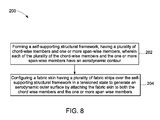
- FIG. 8 is flow chart 200 of a method of manufacturing a wind blade in accordance with an embodiment of the present invention.
- the method includes forming a self-supporting structural framework, having multiple chord-wise members and one or more span-wise members, wherein each of the plurality of the chord-wise members and the one or more span-wise members have an aerodynamic contour.
- the method includes integrating the chord-wise members and the one or more span-wise members, the plurality of pre-fabricated trailing edge and leading edge sections at root section of the wind blade.
- the method also includes forming the self-supporting structural framework by interconnecting opposing spar caps with a shear web structure, wherein the plurality of ribs are connected with spar caps.
- the method also includes configuring a fabric skin having multiple fabric strips over the self-supporting structural framework in a tensioned state to generate an aerodynamic outer surface by attaching the fabric skin to both the chord wise members and the one or more span wise members.
- the method includes assembling a plurality of pre-fabricated trailing edge and leading edge sections, wherein each of the sections comprise a precut tension fabric skin attached to a plurality of leading flexible strips and a plurality of trailing flexible strips at edges of the precut tension fabric skin.
- the method includes assembling a plurality of pre-fabricated trailing edge and leading edge sections, wherein each of the sections comprise a precut tension fabric skin attached to a rigid frame at the edges of the precut tension fabric skin.
Landscapes
- Engineering & Computer Science (AREA)
- Life Sciences & Earth Sciences (AREA)
- Sustainable Development (AREA)
- Sustainable Energy (AREA)
- Chemical & Material Sciences (AREA)
- Combustion & Propulsion (AREA)
- Mechanical Engineering (AREA)
- General Engineering & Computer Science (AREA)
- Wind Motors (AREA)
Abstract
Description
- The present application relates generally to wind turbines and more particularly relates to wind turbine rotor blades having a tension fabric skin structure.
- Most environment friendly energy sources presently available come from wind power that is considered to be one of the cleanest. In this regard, wind turbines have gained increased attention. Wind turbines generate electricity by effectively harnessing energy in the wind via a rotor having a set of rotor blades that turns a gearbox and generator, thereby converting mechanical energy to electrical energy that may be deployed to a utility grid. The construction of a modem rotor blade generally includes skin or shell components, span-wise extending spar caps, and one or more shear webs. Present technology uses several molds to fabricate the various pieces of the blade that are bonded together in large resin-infused molds. Such finished blades are relatively heavy and includes a hardened shell encasing the molded hardened shear webs or spar caps. This leads to difficulty in transportation and assembly of the wind turbines. Further, the size, shape, and weight of rotor blades are factors that contribute to energy efficiencies of wind turbines. An increase in rotor blade size increases the energy production of a wind turbine, while a decrease in weight furthers the efficiency of a wind turbine. Furthermore, as rotor blade sizes grow, extra attention needs to be given to the structural integrity of the rotor blades. Accordingly, efforts to increase rotor blade length, decrease rotor blade weight, and increase rotor blade strength, while also improving rotor blade aerodynamics, aid in the continuing growth of wind turbine technology and the adoption of wind energy as an alternative energy source.
- There is therefore a desire for an improved rotor blade and method for assembling such a rotor blade for a wind turbine would be desired in the art. Such wind blades should improve overall system efficiency while being inexpensive to fabricate and providing a long lifetime.
- In accordance with an embodiment of the invention, a wind blade is provided. The wind blade includes a self-supporting structural framework, having multiple chord-wise members and one or more span-wise members. Each of the multiple chord-wise members and the one or more span-wise members have an aerodynamic contour. The wind blade also comprises a fabric skin located over the self-supporting structural framework in a tensioned state to generate an aerodynamic surface, wherein the fabric skin is attached via multiple tensioning members to both the chord wise members and span wise members.
- In accordance with an embodiment of the invention, a method of manufacturing a wind blade is provided. The method includes forming a self-supporting structural framework, having multiple chord-wise members and one or more span-wise members, wherein each of the plurality of the chord-wise members and the one or more span-wise members have an aerodynamic contour. The method also includes configuring a fabric skin having multiple fabric strips over the self-supporting structural framework in a tensioned state to generate an aerodynamic outer surface by attaching the fabric skin to both the chord wise members and the one or more span wise members.
- In accordance with an embodiment of the invention, a wind turbine is provided. The wind turbine includes multiple wind blades, wherein each of the blades comprises a self-supporting structural framework, having multiple chord-wise members and one or more span-wise members. Each of the multiple chord-wise members and the one or more span-wise members have an aerodynamic contour. The wind turbine also includes a fabric skin located over the self-supporting structural framework in a tensioned state to generate an aerodynamic surface, wherein the fabric skin is attached via multiple tensioning members to both the chord wise members and span wise members.
- Various features, aspects, and advantages of the present invention will become better understood when the following detailed description is read with reference to the accompanying drawings in which like characters represent like parts throughout the drawings, wherein:
-
FIG. 1 is a side view of a wind turbine in accordance with an embodiment of the present invention. -
FIG. 2 is a perspective view of a rotor blade in accordance with an embodiment of the present invention. -
FIG. 3 is a perspective view of the rotor blade with chord-wise and span-wise members and tension fabric skin in accordance with an embodiment of the present invention. -
FIG. 4 shows a portion of the rotor blade having airfoil shaped reinforcing ribs connected via multiple truss elements in accordance with an embodiment of the present invention. -
FIG. 5 shows an assembly of a wind blade that includes pre-fabricated sections in accordance with an embodiment of the present invention. -
FIG. 6 shows a cross-section side view of the assembly of the wind blade in accordance with an embodiment of the present invention. -
FIG. 7 shows an assembly of a wind blade that includes pre-fabricated sections in accordance with another embodiment of the present invention. -
FIG. 8 is flow chart of a method of manufacturing a wind blade in accordance with an embodiment of the present invention. - When introducing elements of various embodiments of the present invention, the articles "a," "an," "the," and "said" are intended to mean that there are one or more of the elements. The terms "comprising," "including," and "having" are intended to be inclusive and mean that there may be additional elements other than the listed elements. Any examples of operating parameters are not exclusive of other parameters of the disclosed embodiments.
-
FIG. 1 is a perspective view of anexemplary wind turbine 10 in accordance with an embodiment of the present invention. In this embodiment, thewind turbine 10 is a horizontal-axis wind turbine. Alternatively, thewind turbine 10 may be a vertical-axis wind turbine. In the present embodiment, thewind turbine 10 includes atower 12 that extends from asupport surface 14, anacelle 16 mounted on thetower 12, agenerator 18 positioned within thenacelle 16, agearbox 20 coupled to thegenerator 18, and arotor 22 that is rotatably coupled to thegearbox 20 with arotor shaft 24. Therotor 22 includes arotatable hub 26 and at least onerotor blade 28 coupled to and extending outward from therotatable hub 26. -
FIG. 2 is a perspective view of arotor blade 28 in accordance with an embodiment of the present invention. Therotor blade 28 includes apressure side 32 and a suction side 34 extending between a leadingedge 36 and atrailing edge 38, and may extend from ablade tip 42 to ablade root 44. The exterior surfaces may be generally aerodynamic surfaces having generally aerodynamic contours, as is generally known in the art. Therotor blade 28 further includes a fabric skin with multipleindividual fabric sections 50 between theblade tip 42 and theblade root 44. Each offabric sections 50 may be uniquely configured so that themultiple fabric sections 50 define acomplete rotor blade 28 having a designed aerodynamic profile. For example, each of thefabric sections 50 may have an aerodynamic profile that corresponds to the aerodynamic profile ofadjacent section 50. Thus, the aerodynamic profiles of thefabric sections 50 may form a continuous aerodynamic profile of therotor blade 28. Therotor blade 28 may further define achord 52 and aspan 54 extending in chord-wise and span-wise directions, respectively. As shown, thechord 52 may vary throughout thespan 54 of therotor blade 28. -
FIG. 3 illustrates further details of therotor blade 28 in accordance with an embodiment of the present invention. Therotor blade 28 includes a self-supportingstructural framework 60 that extents span-wise from the blade root 44 (shown inFIG. 2 ) towards the blade tip 42 (as shown inFIG. 2 ). The self-supportingstructural framework 60 includes multiple chord-wise members and one or more span-wise members. Each of the multiple chord-wise members and the one or more span-wise members have an aerodynamic contour. As shown, the one or more span-wise members include aninternal support structure 62, a leadingedge reinforcement member 64 and a trailingedge reinforcement member 66. Further, theinternal support structure 62 is formed from a single shear web 68 and associatedspar caps 70 that run span-wise along thepressure side 32 and suction side 34 of theblade 28. Thisinternal support structure 62 provides for rigidity and dimensional stability to thewind blade 28. In a non-limiting example, theinternal support structure 62 includes a cross-section geometry with an I-beam shape or hat shape, C-shape, U-shape, T-shape, or combinations thereof. The multiple chord-wise members include multiple airfoil shaped reinforcingribs 72 arranged in chord-wise orientation. Theribs 72 are attached to the leadingedge reinforcement member 64 on one side, the trailingedge reinforcement member 66 on the other side and spaced along theinternal support structure 62. In one embodiment, the multiple chord wise members include multiple airfoil shaped solid or hollow hoops. In one embodiment as shown inFIG. 4 , the airfoil shapedreinforcing ribs 72 are connected viamultiple truss elements 80 that provide additional strength to the overall self-supportingstructural framework 60 of thewind blade 28. - Further,
FIG. 3 shows therotor blade 28 having the fabric skin with multipleindividual fabric sections 50 located over the self-supporting structural framework in a tensioned state to generate an aerodynamic surface. The fabric skin is attached via multiple tensioning members to both the chord wise members and span wise members. The fabric skin also includes multiple fabric strips 74 attached to the multiple chord-wise members and/or the one or more span-wise members via the tensioning members. Non-limiting examples of materials of the tensioning members include extruded metal, roll formed metal and molded or pultruded polymer matrix composites. Further, each of the fabric strips 74 includes a fabric dimension smaller than a dimension of each of the chord-wise members and/or the one or more span-wise members such that the multiple fabric strips 74 are in tension when attached with the chord-wise members and/or the one or more span-wise members. - Furthermore, the fabric skin of the
wind blade 28 includes reinforcing fibers and stretchable matrix materials. In one embodiment, the stretchable matrix material of the fabric skin has an elongation of greater than 10%. Non-limiting examples of the stretchable matrix materials include elastomers, PTFE, ETFE, PU, PVC, silicone, nitrile rubber, EPDM rubber, natural rubber, thermoplastic elastomers, thermoplastic vulcanizates, and combinations thereof. The natural rubber may be unsaturated rubbers and saturated rubbers, wherein non-limiting examples of the unsaturated rubbers comprises Natural polyisoprene: cis-1,4-polyisoprene natural rubber (NR) and trans-1,4-polyisoprene gutta-percha, Synthetic polyisoprene (IR for Isoprene Rubber), Polybutadiene (BR for Butadiene Rubber), Chloroprene rubber (CR), polychloroprene, Neoprene, Baypren; Butyl rubber (copolymer of isobutylene and isoprene, IIR), Halogenated butyl rubbers (chloro butyl rubber: CIIR; bromo butyl rubber: BIIR), Styrene-butadiene Rubber (copolymer of styrene and butadiene, SBR), Nitrile rubber (copolymer of butadiene and acrylonitrile, NBR), also called Buna N rubbers, Hydrogenated Nitrile Rubbers (HNBR) Therban and Zetpol. The unsaturated rubbers can be cured by sulfur vulcanization or non-sulfur vulcanization. - Non-limiting examples of saturated rubbers include EPM (ethylene propylene rubber, a copolymer of ethylene and propylene) and EPDM rubber (ethylene propylene diene rubber, a terpolymer of ethylene, propylene and a diene-component); Epichlorohydrin rubber (ECO), Polyacrylic rubber (ACM, ABR), Silicone rubber (SI, Q, VMQ), Fluorosilicone Rubber (FVMQ), Fluoroelastomers (FKM, and FEPM) Viton, Tecnoflon, Fluorel, Aflas and Dai-El, Perfluoroelastomers (FFKM) Tecnoflon PFR, Kalrez, Chemraz, Perlast, Polyether block amides (PEBA), Chlorosulfonated polyethylene (CSM), (Hypalon) and Ethylene-vinyl acetate (EVA). Advantageously, the fabric skin does not break under buckling conditions due the compliant nature of the stretchable matrix material.
- The reinforcing fibers of the fabric skin may include a first layer of woven fabric material or non-crimp woven fabric material. Non-limiting examples of the reinforcing fibers comprises a glass-fiber, carbon fiber, Kevlar fiber, a natural fiber, a polymeric fiber and combinations thereof. Further, non-limiting examples of the natural fibers include flax, hemp, keneaf, bamboo, jute, banana, silk, sisal, pineapple, rime, and cotton. Furthermore, non-limiting examples of the polymeric fiber include Kevlar, polyester, ultem, propylene, and polyethylene.
- The fabric skin of the
wind blade 28 also includes one or more layers of coatings. The one or more layers of coatings include stretchable matrix materials. In one embodiment, the fabric skin of thewind blade 28 includes the one or more layer of coatings on either side of the first layer of woven fabric material or non-crimp woven fabric material. In another embodiment, the fabric skin of thewind blade 28 may include only one layer of coating. Further, the fabric skin thickness may be about 0.05 millimeters to about 5 millimeters. -
FIG. 5 shows an assembly of awind blade 100 that includes pre-fabricated sections in accordance with an embodiment of the present invention. Thewind blade 100 includes one or more pre-fabricatedspan-wise members 102. In one embodiment, the one or more pre-fabricatedspan-wise members 102 include a prefabricated spar cap with co-infused metal flange encapsulated with biax fabric. Further, thewind blade 100 includes multiple pre-fabricatedleading edge sections 104 having afabric skin 106 with agasket 108 sewn into the edges of thefabric skin 106. Thewind blade 100 also includes a leadingedge form layer 110 adjacent to thefabric skin 106 for maintaining the shape of the leading edge of the pre-fabricatedleading edge section 104. Thewind blade 100 also includes one or more pre-fabricatedtrailing edge sections 112 having thefabric skin 114 with agasket 116 sewn into the edges of thefabric skin 114. Thefabric skin 114 is a precut tension fabric with a smaller geometry for setting the tension in the pre-fabricatedtrailing edge section 112. The pre-fabricatedtrailing edge section 112 further includes support braces 117 that help in transfer pressure loads evenly in the trailing edge sections of thewind blade 100. As shown, thewind blade 100 includes metal orplastic frames 118 withrivet holes 120 for mounting onto the self-supporting structure framework for simple on-tower replacement and local tension control. Thewind blade 100 also includes a trailingedge reinforcement section 122 for providing rigidity to the trailing edge of the blade. In one embodiment, each of the multiple pre-fabricatedleading edge sections 104 comprises a first precut tension fabric skin attached to a plurality of leading flexible strips at edges of the first precut tension fabric skin. In another embodiment, each of the multiple pre-fabricatedtrailing edge sections 118 comprises a second precut tension fabric skin attached to a plurality of trailing flexible strips at edges of the second precut tension fabric skin. -
FIG. 6 shows a cross-section side view of the assembly of thewind blade 100. As shown, thewind blade 100 includes a prefabricated castrubber trailing edge 124 assembled by riveting with the trailingedge reinforcement section 122 using the metal or plastic frames 118. -
FIG. 7 shows an assembly of awind blade 150 that includes pre-fabricated sections in accordance with another embodiment of the present invention. In this embodiment, the pre-fabricatedtrailing edge section 112 further includes support braces 121 that help in transfer pressure loads evenly in the trailing edge sections of thewind blade 100. Thewind blade 150 includes the prefabricated castrubber trailing edge 124 assembled by riveting with the trailingedge reinforcement section 122 using the metal or plastic frames 118. In one embodiment, each of the plurality of pre-fabricatedleading edge sections 104 comprises a first precut tension fabric skin attached to a rigid frame at the edges of the first precut tension fabric skin. In another embodiment, each of the plurality of pre-fabricatedtrailing edge sections 112 comprises a second precut tension fabric skin attached to a rigid frame at the edges of the second precut tension fabric skin. -
FIG. 8 isflow chart 200 of a method of manufacturing a wind blade in accordance with an embodiment of the present invention. Atstep 202, the method includes forming a self-supporting structural framework, having multiple chord-wise members and one or more span-wise members, wherein each of the plurality of the chord-wise members and the one or more span-wise members have an aerodynamic contour. The method includes integrating the chord-wise members and the one or more span-wise members, the plurality of pre-fabricated trailing edge and leading edge sections at root section of the wind blade. The method also includes forming the self-supporting structural framework by interconnecting opposing spar caps with a shear web structure, wherein the plurality of ribs are connected with spar caps. Further, atstep 204, the method also includes configuring a fabric skin having multiple fabric strips over the self-supporting structural framework in a tensioned state to generate an aerodynamic outer surface by attaching the fabric skin to both the chord wise members and the one or more span wise members. In one embodiment, the method includes assembling a plurality of pre-fabricated trailing edge and leading edge sections, wherein each of the sections comprise a precut tension fabric skin attached to a plurality of leading flexible strips and a plurality of trailing flexible strips at edges of the precut tension fabric skin. In a second embodiment, the method includes assembling a plurality of pre-fabricated trailing edge and leading edge sections, wherein each of the sections comprise a precut tension fabric skin attached to a rigid frame at the edges of the precut tension fabric skin. - Furthermore, the skilled artisan will recognize the interchangeability of various features from different embodiments. Similarly, the various method steps and features described, as well as other known equivalents for each such methods and feature, can be mixed and matched by one of ordinary skill in this art to construct additional systems and techniques in accordance with principles of this disclosure. Of course, it is to be understood that not necessarily all such objects or advantages described above may be achieved in accordance with any particular embodiment. Thus, for example, those skilled in the art will recognize that the systems and techniques described herein may be embodied or carried out in a manner that achieves or optimizes one advantage or group of advantages as taught herein without necessarily achieving other objects or advantages as may be taught or suggested herein.
- While only certain features of the invention have been illustrated and described herein, many modifications and changes will occur to those skilled in the art. It is, therefore, to be understood that the appended claims are intended to cover all such modifications and changes as fall within the true spirit of the invention.
- Various aspects and embodiments of the present invention are defined by the following numbered clauses:
- 1. A wind blade comprising:
- a self-supporting structural framework, having a plurality of chord-wise members and one or more span-wise members, wherein each of the plurality of the chord-wise members and the one or more span-wise members have an aerodynamic contour; and
- a fabric skin located over the self-supporting structural framework in a tensioned state to generate an aerodynamic surface, wherein the fabric skin is attached via a plurality of tensioning members to both the chord wise members and span wise members.
- 2. The wind blade of clause 1, wherein the fabric skin comprises reinforcing fibers and stretchable matrix materials.
- 3. The wind blade of any preceding clause, wherein the stretchable matrix material has an elongation of greater than 10%.
- 4. The wind blade of any preceding clause, wherein the stretchable matrix material is selected from the group consisting of elastomers, PTFE, ETFE, PU, PVC, silicone, nitrile rubber, EPDM rubber, natural rubber, thermoplastic elastomers, thermoplastic vulcanizates, and combinations thereof.
- 5. The wind blade of any preceding clause, wherein the reinforcing fibers include a first layer of woven fabric material or non-crimp woven fabric.
- 6. The wind blade of any preceding clause, wherein the reinforcing fibers in the first layer of woven fabric material or non-crimp woven fabric has a modulus greater than 1msi.
- 7. The wind blade of any preceding clause, wherein the reinforcing fibers is selected from the group consisting of a glass-fiber, carbon fiber, Kevlar fiber, a natural fiber, a polymeric fiber and combinations thereof.
- 8. The wind blade of any preceding clause, wherein the fabric skin comprises one or more layers of coatings on either side of the first layer of woven fabric material or non-crimp woven fabric, wherein the one or more layers of coatings include stretchable matrix materials.
- 9. The wind blade of any preceding clause, wherein a thickness of the fabric skin is about 0.05 millimeters to about 5 millimeters.
- 10. The wind blade of any preceding clause, wherein the fabric skin does not break under buckling conditions.
- 11. The wind blade of any preceding clause, wherein the fabric skin comprises a plurality of fabric strips attached to the plurality of chord-wise members and the one or more span-wise members via the tensioning members.
- 12. The wind blade of any preceding clause, wherein each of the fabric strips comprises a fabric dimension smaller than a dimension of each of the chord-wise members and the one or more span-wise members such that the plurality of fabric strips are in tension when attached with the chord-wise members and/or the one or more span-wise members.
- 13. The wind blade of any preceding clause, wherein the plurality of the chord wise members comprises a plurality of airfoil shaped reinforcing ribs.
- 14. The wind blade of any preceding clause, wherein each of the reinforcing ribs are attached to the one or more span-wise members, which one or more span-wise members includes an internal support structure with a cross-section geometry of an I-beam shape or hat shape, C-shape, U-shape, T-shape, solid or hollow rectangular bar, or combinations thereof.
- 15. The wind blade of any preceding clause, wherein the plurality of airfoil shaped reinforcing ribs are connected via a plurality of truss elements.
- 16. The wind blade of any preceding clause, wherein the plurality of the chord wise members comprises a plurality of airfoil shaped solid or hollow hoops.
- 17. The wind blade of any preceding clause, wherein the tensioning members comprises a material selected from a group of extruded metal, roll formed metal, and molded or pultruded polymer matrix composites.
- 18. The wind blade of any preceding clause, further comprising a plurality of pre-fabricated leading edge sections, wherein each of the plurality of pre-fabricated leading edge sections comprises a first precut tension fabric skin attached to a plurality of leading flexible strips at edges of the first precut tension fabric skin.
- 19. The wind blade of any preceding clause, further comprising a plurality of pre-fabricated trailing edge sections, wherein each of the plurality of pre-fabricated trailing edge sections comprises a second precut tension fabric skin attached to a plurality of trailing flexible strips at edges of the second precut tension fabric skin.
- 20. The wind blade of any preceding clause, further comprising a plurality of pre-fabricated leading edge sections, wherein each of the plurality of pre-fabricated leading edge sections comprises a first precut tension fabric skin attached to a rigid frame at the edges of the first precut tension fabric skin.
- 21. The wind blade of any preceding clause, further comprising a plurality of pre-fabricated trailing edge sections, wherein each of the plurality of pre-fabricated trailing edge sections comprises a second precut tension fabric skin attached to a rigid frame at the edges of the second precut tension fabric skin.
- 22. A method of manufacturing a wind blade, the method comprising:
- forming a self-supporting structural framework, having a plurality of chord-wise members and one or more span-wise members, wherein each of the plurality of the chord-wise members and the one or more span-wise members have an aerodynamic contour; and
- configuring a fabric skin having a plurality of fabric strips over the self-supporting structural framework in a tensioned state to generate an aerodynamic outer surface by attaching the fabric skin to both the chord wise members and the one or more span wise members.
- 23. The method of any preceding clause, further comprising assembling a plurality of pre-fabricated trailing edge and leading edge sections, wherien each of the sections comprise a precut tension fabric skin attached to a plurality of leading flexible strips and a plurality of trailing flexible strips at edges of the precut tension fabric skin.
- 24. The method of any preceding clause, further comprising integrating the chord-wise members and the one or more span-wise members, the plurality of pre-fabricated trailing edge and leading edge sections at root section of the wind blade.
- 25. The method of any preceding clause, further comprising forming the self-supporting structural framework by interconnecting opposing spar caps with a shear web structure , wherein the plurality of ribs are connected with spar caps.
- 26. A wind turbine comprising:
- a plurality of wind blades, wherein each of the blade comprises:
- a self-supporting structural framework, having a plurality of chord-wise members and one or more span-wise members, wherein each of the plurality of the chord-wise members and the one or more span-wise members have an aerodynamic contour; and
- a fabric skin located over the self-supporting structural framework in a tensioned state to generate an aerodynamic surface, wherein the fabric skin is attached via a plurality of tensioning members to both the chord wise members and span wise members.
- a plurality of wind blades, wherein each of the blade comprises:
Claims (15)
- A wind blade (28) comprising:a self-supporting structural framework (60), having a plurality of chord-wise members and one or more span-wise members (62), wherein each of the plurality of the chord-wise members and the one or more span-wise members (62) have an aerodynamic contour; anda fabric skin (50) located over the self-supporting structural framework in a tensioned state to generate an aerodynamic surface, wherein the fabric skin (50) is attached via a plurality of tensioning members to both the chord wise members and span wise members (62).
- The wind blade (28) of claim 1, wherein the fabric skin (50) comprises reinforcing fibers and stretchable matrix materials.
- The wind blade (28) of claim 2, wherein the stretchable matrix material has an elongation of greater than 10%.
- The wind blade (28) of claim 2 or claim 3, wherein the stretchable matrix material is selected from the group consisting of elastomers, PTFE, ETFE, PU, PVC, silicone, nitrile rubber, EPDM rubber, natural rubber, thermoplastic elastomers, thermoplastic vulcanizates, and combinations thereof.
- The wind blade (28) of any of claims 2 to 4, wherein the reinforcing fibers include a first layer of woven fabric material or non-crimp woven fabric.
- The wind blade (28) of claim 5, wherein the reinforcing fibers in the first layer of woven fabric material or non-crimp woven fabric has a modulus greater than 1msi.
- The wind blade (28) of claim 5 or claim 6, wherein the reinforcing fibers is selected from the group consisting of a glass-fiber, carbon fiber, Kevlar fiber, a natural fiber, a polymeric fiber and combinations thereof.
- The wind blade (28) of any preceding claim, wherein the fabric skin comprises one or more layers of coatings on either side of the first layer of woven fabric material or non-crimp woven fabric, wherein the one or more layers of coatings include stretchable matrix materials.
- The wind blade (28) of any preceding claim, wherein a thickness of the fabric skin (50) is about 0.05 millimeters to about 5 millimeters.
- The wind blade (28) of any preceding claim, wherein the fabric skin (50) does not break under buckling conditions.
- The wind blade (28) of any preceding claim, wherein the fabric skin (50) comprises a plurality of fabric strips attached to the plurality of chord-wise members and the one or more span-wise members via the tensioning members.
- The wind blade (28) of claim 11, wherein each of the fabric strips comprises a fabric dimension smaller than a dimension of each of the chord-wise members (62) and the one or more span-wise members such that the plurality of fabric strips are in tension when attached with the chord-wise members and/or the one or more span-wise members.
- A method (200) of manufacturing a wind blade (28), the method comprising:forming (202) a self-supporting structural framework (60), having a plurality of chord-wise members and one or more span-wise members, wherein each of the plurality of the chord-wise members and the one or more span-wise members have an aerodynamic contour; andconfiguring (204) a fabric skin (50) having a plurality of fabric strips (74) over the self-supporting structural framework in a tensioned state to generate an aerodynamic outer surface by attaching the fabric skin to both the chord wise members and the one or more span wise members (62).
- The method (200) of claim 13, further comprising assembling a plurality of pre-fabricated trailing edge and leading edge sections, wherien each of the sections comprise a precut tension fabric skin attached to a plurality of leading flexible strips and a plurality of trailing flexible strips at edges of the precut tension fabric skin (50).
- The method (200) of claim 13 or claim 14, further comprising integrating the chord-wise members and the one or more span-wise members, the plurality of pre-fabricated trailing edge and leading edge sections at root section of the wind blade (28).
Applications Claiming Priority (1)
| Application Number | Priority Date | Filing Date | Title |
|---|---|---|---|
| US13/665,148 US9188102B2 (en) | 2012-10-31 | 2012-10-31 | Wind turbine blades with tension fabric skin structure |
Publications (3)
| Publication Number | Publication Date |
|---|---|
| EP2728168A2 true EP2728168A2 (en) | 2014-05-07 |
| EP2728168A3 EP2728168A3 (en) | 2018-04-11 |
| EP2728168B1 EP2728168B1 (en) | 2023-05-31 |
Family
ID=49486357
Family Applications (1)
| Application Number | Title | Priority Date | Filing Date |
|---|---|---|---|
| EP13190272.8A Active EP2728168B1 (en) | 2012-10-31 | 2013-10-25 | Wind turbine blades with tension fabric skin structure |
Country Status (4)
| Country | Link |
|---|---|
| US (1) | US9188102B2 (en) |
| EP (1) | EP2728168B1 (en) |
| CN (1) | CN103790788B (en) |
| AU (1) | AU2013248200B2 (en) |
Families Citing this family (17)
| Publication number | Priority date | Publication date | Assignee | Title |
|---|---|---|---|---|
| US10150233B2 (en) * | 2013-03-19 | 2018-12-11 | The Boeing Company | Method and apparatus for reducing ply wrinkling of composite laminates during forming |
| CN104728056B (en) * | 2015-03-27 | 2018-04-13 | 丁健威 | A kind of blade of wind-driven generator of Combined bamboo offset plate structure |
| KR101731951B1 (en) * | 2016-06-21 | 2017-05-11 | 한국항공대학교산학협력단 | Blade for wind power generator |
| KR101694432B1 (en) * | 2016-06-21 | 2017-01-09 | 한국항공대학교산학협력단 | Blade for wind power generator |
| KR101746643B1 (en) * | 2016-06-21 | 2017-06-13 | 한국항공대학교산학협력단 | Skin for blade suitable for fluid structure and blade suitable for fluid structure with same |
| CN106670731B (en) * | 2016-07-14 | 2018-07-31 | 安徽安凯汽车股份有限公司 | A kind of production method examined for car windshield with the tooling of covering positioning |
| GB201620543D0 (en) | 2016-12-02 | 2017-01-18 | Act Blade Ltd | Wind turbine blade |
| US10794358B2 (en) | 2017-03-17 | 2020-10-06 | Primo Energy, Inc. | High torque wind turbine blade, turbine, and associated systems and methods |
| US9797370B1 (en) | 2017-03-17 | 2017-10-24 | Primo Wind, Inc. | High torque wind turbine blade, turbine, and associated systems and methods |
| US11433632B2 (en) * | 2017-06-06 | 2022-09-06 | Vestas Wind Systems A/S | Relating to wind turbine blade manufacture |
| CN109931211A (en) * | 2017-12-19 | 2019-06-25 | 天津松英科技发展有限公司 | High stability protective device for blade of wind-driven generator |
| US11143164B1 (en) | 2018-04-26 | 2021-10-12 | Epic Metals Corporation | Vertical windmill blade |
| CA3098715A1 (en) * | 2018-04-28 | 2019-10-31 | The Research Foundation For The State University Of New York | Flexible wind turbine blade with actively variable twist distribution |
| CN112883503B (en) * | 2020-11-05 | 2021-08-03 | 中国长江三峡集团有限公司 | Numerical simulation method based on the influence of PTFE membrane on the aerodynamic characteristics of fan blades |
| CN119731079A (en) * | 2022-06-27 | 2025-03-28 | 螺旋体工业有限公司 | High impact resistance reinforcing fibers for leading edge protection of aerodynamic structures |
| CN116557206A (en) * | 2023-06-07 | 2023-08-08 | 远大可建科技有限公司 | A wind power generation blade structure |
| US12320328B1 (en) * | 2024-12-05 | 2025-06-03 | King Saud University | Wind turbine blade made with date palm tree material |
Family Cites Families (20)
| Publication number | Priority date | Publication date | Assignee | Title |
|---|---|---|---|---|
| US4697988A (en) | 1986-02-04 | 1987-10-06 | Her Majesty The Queen In Right Of Canada, As Represented By The Minister Of Energy & Natural Resources | Reinforced delta-wing blade for wind turbine |
| DK175718B1 (en) * | 2002-04-15 | 2005-02-07 | Ssp Technology As | Möllevinge |
| US20080159870A1 (en) * | 2006-12-14 | 2008-07-03 | Hontek Corporation | Method and coating for protecting and repairing an airfoil surface using molded boots, sheet or tape |
| US7517198B2 (en) * | 2006-03-20 | 2009-04-14 | Modular Wind Energy, Inc. | Lightweight composite truss wind turbine blade |
| US7896609B2 (en) | 2006-08-09 | 2011-03-01 | Sri Vawt, Inc. | Vertical axis wind turbine system |
| WO2008070151A2 (en) | 2006-12-06 | 2008-06-12 | Windtronix Energy, Inc. | Improved renewable energy apparatus and method for operating the same |
| ES2342638B1 (en) * | 2007-02-28 | 2011-05-13 | GAMESA INNOVATION & TECHNOLOGY, S.L. | A MULTI-PANEL AIRPLANE SHOVEL. |
| GB0717690D0 (en) * | 2007-09-11 | 2007-10-17 | Blade Dynamics Ltd | Wind turbine blade |
| US8171633B2 (en) * | 2007-12-19 | 2012-05-08 | General Electric Company | Method for assembling a multi-segment wind turbine blade |
| FR2927377B1 (en) | 2008-02-12 | 2010-06-11 | Thales Sa | PROCESS FOR ACTIVE DEFORMATION OF AERODYNAMIC PROFILE |
| US8678324B2 (en) * | 2008-02-21 | 2014-03-25 | Cornerstone Research Group, Inc. | Passive adaptive structures |
| US8899923B2 (en) | 2008-10-14 | 2014-12-02 | Vestas Wind Systems A/S | Wind turbine blade with device for changing the aerodynamic surface or shape |
| DK2358998T3 (en) | 2008-12-05 | 2017-10-30 | Vestas Wind Sys As | EFFICIENT WINDOWS, WINDOWS, AND ASSOCIATED SYSTEMS AND PROCEDURES FOR MANUFACTURING, INSTALLING AND USING |
| US20120045332A1 (en) | 2009-03-09 | 2012-02-23 | Windjoule Ltd | Vertical axis wind turbine |
| US7938623B2 (en) * | 2009-03-26 | 2011-05-10 | General Electric Company | Inflatable wind turbine blade and method for forming said rotor blade |
| US7854594B2 (en) * | 2009-04-28 | 2010-12-21 | General Electric Company | Segmented wind turbine blade |
| GB2469854A (en) | 2009-04-30 | 2010-11-03 | Vestas Wind Sys As | Wind turbine rotor blade |
| US8178987B2 (en) | 2009-05-20 | 2012-05-15 | E-Net, Llc | Wind turbine |
| KR101315841B1 (en) * | 2011-01-26 | 2013-10-14 | 후지쿠라 고무 코교 가부시끼가이샤 | Wing blade and laminated protective sheet thereof |
| US8360732B2 (en) * | 2011-05-25 | 2013-01-29 | General Electric Company | Rotor blade section and method for assembling a rotor blade for a wind turbine |
-
2012
- 2012-10-31 US US13/665,148 patent/US9188102B2/en active Active
-
2013
- 2013-10-24 AU AU2013248200A patent/AU2013248200B2/en active Active
- 2013-10-25 EP EP13190272.8A patent/EP2728168B1/en active Active
- 2013-10-31 CN CN201310529725.5A patent/CN103790788B/en active Active
Non-Patent Citations (1)
| Title |
|---|
| None |
Also Published As
| Publication number | Publication date |
|---|---|
| AU2013248200A1 (en) | 2014-05-15 |
| CN103790788A (en) | 2014-05-14 |
| AU2013248200B2 (en) | 2016-12-22 |
| US9188102B2 (en) | 2015-11-17 |
| US20140119940A1 (en) | 2014-05-01 |
| EP2728168A3 (en) | 2018-04-11 |
| CN103790788B (en) | 2018-11-13 |
| EP2728168B1 (en) | 2023-05-31 |
Similar Documents
| Publication | Publication Date | Title |
|---|---|---|
| EP2728168B1 (en) | Wind turbine blades with tension fabric skin structure | |
| US8430638B2 (en) | Noise reducer for rotor blade in wind turbine | |
| US9605650B2 (en) | Wind blades with mechanical elements for pretensioning in tension fabrics | |
| US9399919B2 (en) | Extension tip sleeve for wind turbine blade | |
| US8047784B2 (en) | Lift device for rotor blade in wind turbine | |
| US9745956B2 (en) | Spar cap for a wind turbine rotor blade | |
| US10710321B2 (en) | Rotor blade mold assembly and method for forming rotor blade | |
| US10690111B2 (en) | Wind turbine rotor blade | |
| DK178020B1 (en) | SAVE CAP UNIT FOR A WINDOW MILLER CIRCUIT | |
| US10605227B2 (en) | Segmented wind turbine rotor blade with welded joint | |
| US8622707B2 (en) | Root attachment for a rotor blade assembly | |
| EP2463514A2 (en) | Spar assembly for a wind turbine rotor blade | |
| US9890764B2 (en) | Trailing edge cap for a rotor blade and method of manufacturing same | |
| CA2869803C (en) | Noise reducing extension plate for rotor blade in wind turbine | |
| CN105799184A (en) | Methods of manufacturing rotor blade components for a wind turbine | |
| DK201570507A1 (en) | METHODS OF MANUFACTURING ROTOR BLADES OF A WIND TURBINE | |
| US10072632B2 (en) | Spar cap for a wind turbine rotor blade formed from pre-cured laminate plates of varying thicknesses | |
| CA2806793A1 (en) | Blade insert for a wind turbine rotor blade and related methods | |
| CN107676232B (en) | Modularized wind turbine blade structure and assembly method thereof | |
| US9651024B2 (en) | Rotor blade assembly having internal loading features | |
| WO2019018131A1 (en) | Airflow configuration for a wind turbine rotor blade | |
| AU2011226066A1 (en) | Wind turbine rotor blade | |
| BR102014000013A2 (en) | wind blade, wind turbine and wind turbine manufacturing method |
Legal Events
| Date | Code | Title | Description |
|---|---|---|---|
| PUAI | Public reference made under article 153(3) epc to a published international application that has entered the european phase |
Free format text: ORIGINAL CODE: 0009012 |
|
| 17P | Request for examination filed |
Effective date: 20131025 |
|
| AK | Designated contracting states |
Kind code of ref document: A2 Designated state(s): AL AT BE BG CH CY CZ DE DK EE ES FI FR GB GR HR HU IE IS IT LI LT LU LV MC MK MT NL NO PL PT RO RS SE SI SK SM TR |
|
| AX | Request for extension of the european patent |
Extension state: BA ME |
|
| PUAL | Search report despatched |
Free format text: ORIGINAL CODE: 0009013 |
|
| AK | Designated contracting states |
Kind code of ref document: A3 Designated state(s): AL AT BE BG CH CY CZ DE DK EE ES FI FR GB GR HR HU IE IS IT LI LT LU LV MC MK MT NL NO PL PT RO RS SE SI SK SM TR |
|
| AX | Request for extension of the european patent |
Extension state: BA ME |
|
| RIC1 | Information provided on ipc code assigned before grant |
Ipc: F03D 1/06 20060101AFI20180308BHEP |
|
| STAA | Information on the status of an ep patent application or granted ep patent |
Free format text: STATUS: REQUEST FOR EXAMINATION WAS MADE |
|
| 17P | Request for examination filed |
Effective date: 20181011 |
|
| RBV | Designated contracting states (corrected) |
Designated state(s): AL AT BE BG CH CY CZ DE DK EE ES FI FR GB GR HR HU IE IS IT LI LT LU LV MC MK MT NL NO PL PT RO RS SE SI SK SM TR |
|
| STAA | Information on the status of an ep patent application or granted ep patent |
Free format text: STATUS: EXAMINATION IS IN PROGRESS |
|
| 17Q | First examination report despatched |
Effective date: 20191022 |
|
| GRAP | Despatch of communication of intention to grant a patent |
Free format text: ORIGINAL CODE: EPIDOSNIGR1 |
|
| STAA | Information on the status of an ep patent application or granted ep patent |
Free format text: STATUS: GRANT OF PATENT IS INTENDED |
|
| INTG | Intention to grant announced |
Effective date: 20230109 |
|
| GRAS | Grant fee paid |
Free format text: ORIGINAL CODE: EPIDOSNIGR3 |
|
| GRAA | (expected) grant |
Free format text: ORIGINAL CODE: 0009210 |
|
| STAA | Information on the status of an ep patent application or granted ep patent |
Free format text: STATUS: THE PATENT HAS BEEN GRANTED |
|
| AK | Designated contracting states |
Kind code of ref document: B1 Designated state(s): AL AT BE BG CH CY CZ DE DK EE ES FI FR GB GR HR HU IE IS IT LI LT LU LV MC MK MT NL NO PL PT RO RS SE SI SK SM TR |
|
| REG | Reference to a national code |
Ref country code: GB Ref legal event code: FG4D Ref country code: CH Ref legal event code: EP |
|
| REG | Reference to a national code |
Ref country code: DE Ref legal event code: R096 Ref document number: 602013083862 Country of ref document: DE |
|
| REG | Reference to a national code |
Ref country code: AT Ref legal event code: REF Ref document number: 1571068 Country of ref document: AT Kind code of ref document: T Effective date: 20230615 |
|
| REG | Reference to a national code |
Ref country code: IE Ref legal event code: FG4D |
|
| P01 | Opt-out of the competence of the unified patent court (upc) registered |
Effective date: 20230522 |
|
| REG | Reference to a national code |
Ref country code: LT Ref legal event code: MG9D |
|
| REG | Reference to a national code |
Ref country code: NL Ref legal event code: MP Effective date: 20230531 |
|
| REG | Reference to a national code |
Ref country code: AT Ref legal event code: MK05 Ref document number: 1571068 Country of ref document: AT Kind code of ref document: T Effective date: 20230531 |
|
| PG25 | Lapsed in a contracting state [announced via postgrant information from national office to epo] |
Ref country code: SE Free format text: LAPSE BECAUSE OF FAILURE TO SUBMIT A TRANSLATION OF THE DESCRIPTION OR TO PAY THE FEE WITHIN THE PRESCRIBED TIME-LIMIT Effective date: 20230531 Ref country code: NO Free format text: LAPSE BECAUSE OF FAILURE TO SUBMIT A TRANSLATION OF THE DESCRIPTION OR TO PAY THE FEE WITHIN THE PRESCRIBED TIME-LIMIT Effective date: 20230831 Ref country code: ES Free format text: LAPSE BECAUSE OF FAILURE TO SUBMIT A TRANSLATION OF THE DESCRIPTION OR TO PAY THE FEE WITHIN THE PRESCRIBED TIME-LIMIT Effective date: 20230531 Ref country code: AT Free format text: LAPSE BECAUSE OF FAILURE TO SUBMIT A TRANSLATION OF THE DESCRIPTION OR TO PAY THE FEE WITHIN THE PRESCRIBED TIME-LIMIT Effective date: 20230531 |
|
| PG25 | Lapsed in a contracting state [announced via postgrant information from national office to epo] |
Ref country code: RS Free format text: LAPSE BECAUSE OF FAILURE TO SUBMIT A TRANSLATION OF THE DESCRIPTION OR TO PAY THE FEE WITHIN THE PRESCRIBED TIME-LIMIT Effective date: 20230531 Ref country code: PL Free format text: LAPSE BECAUSE OF FAILURE TO SUBMIT A TRANSLATION OF THE DESCRIPTION OR TO PAY THE FEE WITHIN THE PRESCRIBED TIME-LIMIT Effective date: 20230531 Ref country code: NL Free format text: LAPSE BECAUSE OF FAILURE TO SUBMIT A TRANSLATION OF THE DESCRIPTION OR TO PAY THE FEE WITHIN THE PRESCRIBED TIME-LIMIT Effective date: 20230531 Ref country code: LV Free format text: LAPSE BECAUSE OF FAILURE TO SUBMIT A TRANSLATION OF THE DESCRIPTION OR TO PAY THE FEE WITHIN THE PRESCRIBED TIME-LIMIT Effective date: 20230531 Ref country code: LT Free format text: LAPSE BECAUSE OF FAILURE TO SUBMIT A TRANSLATION OF THE DESCRIPTION OR TO PAY THE FEE WITHIN THE PRESCRIBED TIME-LIMIT Effective date: 20230531 Ref country code: IS Free format text: LAPSE BECAUSE OF FAILURE TO SUBMIT A TRANSLATION OF THE DESCRIPTION OR TO PAY THE FEE WITHIN THE PRESCRIBED TIME-LIMIT Effective date: 20230930 Ref country code: HR Free format text: LAPSE BECAUSE OF FAILURE TO SUBMIT A TRANSLATION OF THE DESCRIPTION OR TO PAY THE FEE WITHIN THE PRESCRIBED TIME-LIMIT Effective date: 20230531 Ref country code: GR Free format text: LAPSE BECAUSE OF FAILURE TO SUBMIT A TRANSLATION OF THE DESCRIPTION OR TO PAY THE FEE WITHIN THE PRESCRIBED TIME-LIMIT Effective date: 20230901 |
|
| RAP2 | Party data changed (patent owner data changed or rights of a patent transferred) |
Owner name: GENERAL ELECTRIC RENOVABLES ESPANA, S.L. |
|
| REG | Reference to a national code |
Ref country code: GB Ref legal event code: 732E Free format text: REGISTERED BETWEEN 20231123 AND 20231129 |
|
| PG25 | Lapsed in a contracting state [announced via postgrant information from national office to epo] |
Ref country code: FI Free format text: LAPSE BECAUSE OF FAILURE TO SUBMIT A TRANSLATION OF THE DESCRIPTION OR TO PAY THE FEE WITHIN THE PRESCRIBED TIME-LIMIT Effective date: 20230531 |
|
| REG | Reference to a national code |
Ref country code: DE Ref legal event code: R081 Ref document number: 602013083862 Country of ref document: DE Owner name: GENERAL ELECTRIC RENOVABLES ESPANA S.L., ES Free format text: FORMER OWNER: GENERAL ELECTRIC COMPANY, SCHENECTADY, NY, US Ref country code: DE Ref legal event code: R081 Ref document number: 602013083862 Country of ref document: DE Owner name: LM WIND POWER A/S, DK Free format text: FORMER OWNER: GENERAL ELECTRIC COMPANY, SCHENECTADY, NY, US Ref country code: DE Ref legal event code: R082 Ref document number: 602013083862 Ref country code: DE Ref legal event code: R082 Ref document number: 602013083862 Country of ref document: DE Representative=s name: ZIMMERMANN & PARTNER PATENTANWAELTE MBB, DE |
|
| PG25 | Lapsed in a contracting state [announced via postgrant information from national office to epo] |
Ref country code: SK Free format text: LAPSE BECAUSE OF FAILURE TO SUBMIT A TRANSLATION OF THE DESCRIPTION OR TO PAY THE FEE WITHIN THE PRESCRIBED TIME-LIMIT Effective date: 20230531 |
|
| PG25 | Lapsed in a contracting state [announced via postgrant information from national office to epo] |
Ref country code: SM Free format text: LAPSE BECAUSE OF FAILURE TO SUBMIT A TRANSLATION OF THE DESCRIPTION OR TO PAY THE FEE WITHIN THE PRESCRIBED TIME-LIMIT Effective date: 20230531 Ref country code: SK Free format text: LAPSE BECAUSE OF FAILURE TO SUBMIT A TRANSLATION OF THE DESCRIPTION OR TO PAY THE FEE WITHIN THE PRESCRIBED TIME-LIMIT Effective date: 20230531 Ref country code: RO Free format text: LAPSE BECAUSE OF FAILURE TO SUBMIT A TRANSLATION OF THE DESCRIPTION OR TO PAY THE FEE WITHIN THE PRESCRIBED TIME-LIMIT Effective date: 20230531 Ref country code: PT Free format text: LAPSE BECAUSE OF FAILURE TO SUBMIT A TRANSLATION OF THE DESCRIPTION OR TO PAY THE FEE WITHIN THE PRESCRIBED TIME-LIMIT Effective date: 20231002 Ref country code: EE Free format text: LAPSE BECAUSE OF FAILURE TO SUBMIT A TRANSLATION OF THE DESCRIPTION OR TO PAY THE FEE WITHIN THE PRESCRIBED TIME-LIMIT Effective date: 20230531 Ref country code: DK Free format text: LAPSE BECAUSE OF FAILURE TO SUBMIT A TRANSLATION OF THE DESCRIPTION OR TO PAY THE FEE WITHIN THE PRESCRIBED TIME-LIMIT Effective date: 20230531 Ref country code: CZ Free format text: LAPSE BECAUSE OF FAILURE TO SUBMIT A TRANSLATION OF THE DESCRIPTION OR TO PAY THE FEE WITHIN THE PRESCRIBED TIME-LIMIT Effective date: 20230531 |
|
| REG | Reference to a national code |
Ref country code: DE Ref legal event code: R097 Ref document number: 602013083862 Country of ref document: DE |
|
| REG | Reference to a national code |
Ref country code: DE Ref legal event code: R082 Ref document number: 602013083862 Country of ref document: DE Representative=s name: ZIMMERMANN & PARTNER PATENTANWAELTE MBB, DE |
|
| PLBE | No opposition filed within time limit |
Free format text: ORIGINAL CODE: 0009261 |
|
| STAA | Information on the status of an ep patent application or granted ep patent |
Free format text: STATUS: NO OPPOSITION FILED WITHIN TIME LIMIT |
|
| PG25 | Lapsed in a contracting state [announced via postgrant information from national office to epo] |
Ref country code: SI Free format text: LAPSE BECAUSE OF FAILURE TO SUBMIT A TRANSLATION OF THE DESCRIPTION OR TO PAY THE FEE WITHIN THE PRESCRIBED TIME-LIMIT Effective date: 20230531 |
|
| 26N | No opposition filed |
Effective date: 20240301 |
|
| PG25 | Lapsed in a contracting state [announced via postgrant information from national office to epo] |
Ref country code: SI Free format text: LAPSE BECAUSE OF FAILURE TO SUBMIT A TRANSLATION OF THE DESCRIPTION OR TO PAY THE FEE WITHIN THE PRESCRIBED TIME-LIMIT Effective date: 20230531 Ref country code: IT Free format text: LAPSE BECAUSE OF FAILURE TO SUBMIT A TRANSLATION OF THE DESCRIPTION OR TO PAY THE FEE WITHIN THE PRESCRIBED TIME-LIMIT Effective date: 20230531 Ref country code: MC Free format text: LAPSE BECAUSE OF FAILURE TO SUBMIT A TRANSLATION OF THE DESCRIPTION OR TO PAY THE FEE WITHIN THE PRESCRIBED TIME-LIMIT Effective date: 20230531 |
|
| REG | Reference to a national code |
Ref country code: CH Ref legal event code: PL |
|
| REG | Reference to a national code |
Ref country code: BE Ref legal event code: MM Effective date: 20231031 |
|
| PG25 | Lapsed in a contracting state [announced via postgrant information from national office to epo] |
Ref country code: LU Free format text: LAPSE BECAUSE OF NON-PAYMENT OF DUE FEES Effective date: 20231025 |
|
| PG25 | Lapsed in a contracting state [announced via postgrant information from national office to epo] |
Ref country code: LU Free format text: LAPSE BECAUSE OF NON-PAYMENT OF DUE FEES Effective date: 20231025 |
|
| PG25 | Lapsed in a contracting state [announced via postgrant information from national office to epo] |
Ref country code: CH Free format text: LAPSE BECAUSE OF NON-PAYMENT OF DUE FEES Effective date: 20231031 |
|
| PG25 | Lapsed in a contracting state [announced via postgrant information from national office to epo] |
Ref country code: CH Free format text: LAPSE BECAUSE OF NON-PAYMENT OF DUE FEES Effective date: 20231031 |
|
| PG25 | Lapsed in a contracting state [announced via postgrant information from national office to epo] |
Ref country code: BE Free format text: LAPSE BECAUSE OF NON-PAYMENT OF DUE FEES Effective date: 20231031 |
|
| PG25 | Lapsed in a contracting state [announced via postgrant information from national office to epo] |
Ref country code: IE Free format text: LAPSE BECAUSE OF NON-PAYMENT OF DUE FEES Effective date: 20231025 |
|
| REG | Reference to a national code |
Ref country code: DE Ref legal event code: R082 Ref document number: 602013083862 Country of ref document: DE Ref country code: DE Ref legal event code: R081 Ref document number: 602013083862 Country of ref document: DE Owner name: GENERAL ELECTRIC RENOVABLES ESPANA S.L., ES Free format text: FORMER OWNER: LM WIND POWER A/S, KOLDING, DK |
|
| REG | Reference to a national code |
Ref country code: GB Ref legal event code: 732E Free format text: REGISTERED BETWEEN 20241003 AND 20241009 |
|
| PG25 | Lapsed in a contracting state [announced via postgrant information from national office to epo] |
Ref country code: IE Free format text: LAPSE BECAUSE OF NON-PAYMENT OF DUE FEES Effective date: 20231025 |
|
| PG25 | Lapsed in a contracting state [announced via postgrant information from national office to epo] |
Ref country code: BG Free format text: LAPSE BECAUSE OF FAILURE TO SUBMIT A TRANSLATION OF THE DESCRIPTION OR TO PAY THE FEE WITHIN THE PRESCRIBED TIME-LIMIT Effective date: 20230531 |
|
| PG25 | Lapsed in a contracting state [announced via postgrant information from national office to epo] |
Ref country code: BG Free format text: LAPSE BECAUSE OF FAILURE TO SUBMIT A TRANSLATION OF THE DESCRIPTION OR TO PAY THE FEE WITHIN THE PRESCRIBED TIME-LIMIT Effective date: 20230531 |
|
| PG25 | Lapsed in a contracting state [announced via postgrant information from national office to epo] |
Ref country code: CY Free format text: LAPSE BECAUSE OF FAILURE TO SUBMIT A TRANSLATION OF THE DESCRIPTION OR TO PAY THE FEE WITHIN THE PRESCRIBED TIME-LIMIT; INVALID AB INITIO Effective date: 20131025 |
|
| PG25 | Lapsed in a contracting state [announced via postgrant information from national office to epo] |
Ref country code: HU Free format text: LAPSE BECAUSE OF FAILURE TO SUBMIT A TRANSLATION OF THE DESCRIPTION OR TO PAY THE FEE WITHIN THE PRESCRIBED TIME-LIMIT; INVALID AB INITIO Effective date: 20131025 |
|
| PGFP | Annual fee paid to national office [announced via postgrant information from national office to epo] |
Ref country code: GB Payment date: 20250923 Year of fee payment: 13 |
|
| PGFP | Annual fee paid to national office [announced via postgrant information from national office to epo] |
Ref country code: FR Payment date: 20250925 Year of fee payment: 13 |
|
| PG25 | Lapsed in a contracting state [announced via postgrant information from national office to epo] |
Ref country code: TR Free format text: LAPSE BECAUSE OF FAILURE TO SUBMIT A TRANSLATION OF THE DESCRIPTION OR TO PAY THE FEE WITHIN THE PRESCRIBED TIME-LIMIT Effective date: 20230531 |
|
| PGFP | Annual fee paid to national office [announced via postgrant information from national office to epo] |
Ref country code: DE Payment date: 20250923 Year of fee payment: 13 |