EP2728143A2 - Inlet bleed heat system with integrated air knife/siliencer panels - Google Patents
Inlet bleed heat system with integrated air knife/siliencer panels Download PDFInfo
- Publication number
- EP2728143A2 EP2728143A2 EP13191626.4A EP13191626A EP2728143A2 EP 2728143 A2 EP2728143 A2 EP 2728143A2 EP 13191626 A EP13191626 A EP 13191626A EP 2728143 A2 EP2728143 A2 EP 2728143A2
- Authority
- EP
- European Patent Office
- Prior art keywords
- air
- flow
- bleed
- inlet
- heat system
- Prior art date
- Legal status (The legal status is an assumption and is not a legal conclusion. Google has not performed a legal analysis and makes no representation as to the accuracy of the status listed.)
- Withdrawn
Links
Images

Classifications
-
- F—MECHANICAL ENGINEERING; LIGHTING; HEATING; WEAPONS; BLASTING
- F01—MACHINES OR ENGINES IN GENERAL; ENGINE PLANTS IN GENERAL; STEAM ENGINES
- F01D—NON-POSITIVE DISPLACEMENT MACHINES OR ENGINES, e.g. STEAM TURBINES
- F01D25/00—Component parts, details, or accessories, not provided for in, or of interest apart from, other groups
- F01D25/08—Cooling; Heating; Heat-insulation
-
- F—MECHANICAL ENGINEERING; LIGHTING; HEATING; WEAPONS; BLASTING
- F02—COMBUSTION ENGINES; HOT-GAS OR COMBUSTION-PRODUCT ENGINE PLANTS
- F02C—GAS-TURBINE PLANTS; AIR INTAKES FOR JET-PROPULSION PLANTS; CONTROLLING FUEL SUPPLY IN AIR-BREATHING JET-PROPULSION PLANTS
- F02C7/00—Features, components parts, details or accessories, not provided for in, or of interest apart form groups F02C1/00 - F02C6/00; Air intakes for jet-propulsion plants
- F02C7/04—Air intakes for gas-turbine plants or jet-propulsion plants
- F02C7/045—Air intakes for gas-turbine plants or jet-propulsion plants having provisions for noise suppression
-
- F—MECHANICAL ENGINEERING; LIGHTING; HEATING; WEAPONS; BLASTING
- F02—COMBUSTION ENGINES; HOT-GAS OR COMBUSTION-PRODUCT ENGINE PLANTS
- F02C—GAS-TURBINE PLANTS; AIR INTAKES FOR JET-PROPULSION PLANTS; CONTROLLING FUEL SUPPLY IN AIR-BREATHING JET-PROPULSION PLANTS
- F02C7/00—Features, components parts, details or accessories, not provided for in, or of interest apart form groups F02C1/00 - F02C6/00; Air intakes for jet-propulsion plants
- F02C7/04—Air intakes for gas-turbine plants or jet-propulsion plants
- F02C7/057—Control or regulation
-
- F—MECHANICAL ENGINEERING; LIGHTING; HEATING; WEAPONS; BLASTING
- F01—MACHINES OR ENGINES IN GENERAL; ENGINE PLANTS IN GENERAL; STEAM ENGINES
- F01D—NON-POSITIVE DISPLACEMENT MACHINES OR ENGINES, e.g. STEAM TURBINES
- F01D25/00—Component parts, details, or accessories, not provided for in, or of interest apart from, other groups
- F01D25/08—Cooling; Heating; Heat-insulation
- F01D25/10—Heating, e.g. warming-up before starting
-
- F—MECHANICAL ENGINEERING; LIGHTING; HEATING; WEAPONS; BLASTING
- F02—COMBUSTION ENGINES; HOT-GAS OR COMBUSTION-PRODUCT ENGINE PLANTS
- F02C—GAS-TURBINE PLANTS; AIR INTAKES FOR JET-PROPULSION PLANTS; CONTROLLING FUEL SUPPLY IN AIR-BREATHING JET-PROPULSION PLANTS
- F02C6/00—Plural gas-turbine plants; Combinations of gas-turbine plants with other apparatus; Adaptations of gas- turbine plants for special use
- F02C6/04—Gas-turbine plants providing heated or pressurised working fluid for other apparatus, e.g. without mechanical power output
- F02C6/06—Gas-turbine plants providing heated or pressurised working fluid for other apparatus, e.g. without mechanical power output providing compressed gas
-
- F—MECHANICAL ENGINEERING; LIGHTING; HEATING; WEAPONS; BLASTING
- F05—INDEXING SCHEMES RELATING TO ENGINES OR PUMPS IN VARIOUS SUBCLASSES OF CLASSES F01-F04
- F05D—INDEXING SCHEME FOR ASPECTS RELATING TO NON-POSITIVE-DISPLACEMENT MACHINES OR ENGINES, GAS-TURBINES OR JET-PROPULSION PLANTS
- F05D2260/00—Function
- F05D2260/96—Preventing, counteracting or reducing vibration or noise
Definitions
- the present application and resultant patent relate generally to gas turbine engines and more particularly relate to an inlet bleed heat system for a gas turbine engine having integrated air knife/silencer panels for an improved air flow uniformity and pressure drop.
- Gas turbine engine compressors often include air inlet systems with heating devices for raising the temperature of the incoming air stream.
- Compressor IGV icing, surge/stall, combustion lean blowout, and the like may result due to cold ambient conditions and/or due to other types of operating parameters.
- the compressor pressure ratio may be accommodated by bleeding an amount of compressor discharge air and recirculating the air back to the compressor inlet. Mixing the cooler ambient air with the bleed portion of the hot compressor discharge air reduces the air density and the mass flow to the gas turbine.
- Current inlet bleed heat systems may use impingement holes for air injection in a direction perpendicular to the main airflow direction.
- Other known inlet heat bleed systems may use acoustical nozzles in a filter house transition section for injection in the airflow direction. Many other types of inlet bleed heat control systems and methods of bleed injection also may be used.
- an improved inlet bleed heat system for a gas turbine engine.
- an improved bleed heat system may adequately heat the incoming airflow with a reduced the pressure drop thereacross so as to provide temperature and flow uniformity while complying with relevant noise limitations and other operational parameters.
- the present application and the resultant patent thus provide an inlet bleed heat system for supplying a flow of bleed air to a flow of incoming air into a compressor of a gas turbine engine.
- the inlet bleed heat system may include an air knife and a silencer panel.
- the air knife may include a compressor bleed air port in communication with the flow of bleed air and a discharge gap to discharge the flow of bleed air into the flow of incoming air.
- the air knife and the silencer panel may form an integrated air knife/silencer panel.
- the present application and the resultant patent further may describe a method of providing inlet bleed heat control in a gas turbine engine.
- the method may include the steps of providing a flow of incoming air towards a compressor of the gas turbine engine, flowing the flow of incoming air through a number of integrated air knife/silencer panels, providing a flow of bleed air to the integrated air knife/silencer panels, forcing the flow of bleed air through a discharge gap in each of the integrated air knife/silencer panels, and entraining the flow of the incoming air with the flow of bleed air.
- the present application and the resultant patent further provide a turbine inlet system for providing a flow of incoming air to a compressor of a gas turbine engine.
- the turbine inlet system may include an inlet duct leading to the compressor and an inlet bleed heat system positioned within the inlet duct.
- the inlet bleed heat system may be in communication with a flow of bleed air.
- the inlet bleed heat system may include a number of integrated air knife/silencer panels in communication with the flow of bleed air.
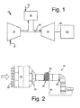
- Fig. 1 shows a schematic view of gas turbine engine 10 as may be used herein.
- the gas turbine engine 10 may include a compressor 15.
- the compressor 15 compresses an incoming flow of air 20.
- the compressor 15 delivers the compressed flow of air 20 to a combustor 25.
- the combustor 25 mixes the compressed flow of air 20 with a pressurized flow of fuel 30 and ignites the mixture to create a flow of combustion gases 35.
- the gas turbine engine 10 may include any number of combustors 25.
- the flow of combustion gases 35 is in turn delivered to a turbine 40.
- the flow of combustion gases 35 drives the turbine 40 so as to produce mechanical work.
- the mechanical work produced in the turbine 40 drives the compressor 15 via a shaft 45 and an external load 50 such as an electrical generator and the like.
- the gas turbine engine 10 may use natural gas, various types of syngas, and/or other types of fuels.
- the gas turbine engine 10 may be any one of a number of different gas turbine engines offered by General Electric Company of Schenectady, New York, including, but not limited to, those such as a 7 or a 9 series heavy duty gas turbine engine and the like.
- the gas turbine engine 10 may have different configurations and may use other types of components.
- Other types of gas turbine engines also may be used herein.
- Multiple gas turbine engines, other types of turbines, and other types of power generation equipment also may be used herein together.
- Fig. 2 is a schematic diagram of a turbine inlet system 55.
- the turbine inlet system 55 may be integrated with the compressor 15 of the gas turbine engine 10 described above and the like.
- the turbine inlet system 55 may include a weatherhood 60.
- the weatherhood 60 may prevent weather elements such as rain, snow, hail, and the like in the flow of air 20 from entering the compressor 15.
- the flow of air 20 then may flow through an inlet filter house 65.
- the inlet filter house 65 may remove foreign objects and debris from the flow of air 20.
- a transition piece 70 may extend downstream of the inlet filter house 65 and extend into an inlet duct 75.
- a silencer section 80 and an inlet bleed heat system 85 may be positioned within the inlet duct 75 or elsewhere in the turbine inlet system 55.
- the silencer section 80 may have any suitable size, shape, or configuration that effectively attenuates, damps, and/or reflects the acoustical energy from the compressor 15.
- the inlet bleed heat system 85 may heat the incoming flow of air 20 with a flow of compressor bleed air 90. As described above, the inlet bleed heat system 85 may use an impingement flow and the like.
- a trash screen 95 and the like may be located downstream of the inlet duct 75 so as to prevent debris from entering the compressor 15.
- the turbine inlet system 55 described herein is for the purposes of example only. Turbine inlet systems of many other configurations and with different components also may be known.
- Fig. 3 shows a turbine inlet system 100 as may be described herewith.
- the turbine inlet system 100 may include a weatherhood 110, an inlet filter house 120, a transition piece 130, and an inlet duct 140.
- the size, shape, and configuration of these components may vary.
- the turbine inlet system 100 may be used with the compressor 15 of the gas turbine engine 10 and the like. Other components and other configurations may be used herein.
- the turbine inlet system 100 also may include an inlet bleed heat system 150.
- the inlet bleed heat system 150 may be positioned within the inlet duct 140 or elsewhere in the turbine inlet system 100.
- the inlet bleed heat system 150 may include a number of air knives 160.
- An "air knife” produces a largely laminar or diffused air flow along its length using a "Coanda” effect that entrains a large volume of air from surrounding areas by a smaller amount of compressed bleed air 90.
- an air knife has no moving parts, is driven by air as opposed to electricity, and may be very quiet. Examples of air knives are sold by Nex Flow Air Products Corporation of Richmond Hill, Ontario, Canada under the designation "Silent X-Stream Air Blade Air Knife and the like. Other types of air injection devices may be used herein.
- the air knife 160 may include a compressor bleed port 170 in communication with the flow of compressor bleed air 90.
- the air knife 160 also may include an internal plenum 180 in communication with the compressor bleed port 170.
- the internal plenum 180 may lead to a discharge gap 190.
- the discharge gap 190 may run along the length of the air knife 160.
- the discharge gap 190 may be sized to accelerate the flow of compressor bleed air 90 therethrough.
- the size, shape, configuration, and angle of the discharge gap 190 may vary and may be optimized herein.
- the discharge gap 190 may be positioned about one or more inwardly curved ends 200.
- the shape and radius of the curved ends 200 may vary.
- the air knives 160 and the elements thereof may have any suitable size, shape, or configuration. Although a horizontal orientation is shown, a vertical orientation also may be used. Any number of the air knives 160 may be used herein. Air knives 160 of differing sizes and configuration also may be used herein together.
- the compressor bleed air 90 thus enters the air knife 160 through the compressor bleed port 170 and exits through the discharge gap 190 about the inwardly curved ends 200.
- the incoming flow of air 20 thus may be entrained about the inwardly curved ends 200 of the air knife 160 by the compressor bleed air 90 exiting the discharge gap 190 under pressure into an entrained flow 210.
- the entrained flow 210 may have a higher velocity and pumping force in a well-defined main flow.
- the entrained flow 210 thus may reduce the pressure drop thereacross because the entrained flow 210 may act largely as an air pump for the incoming flow of air 20.
- Other components and other configurations may be used herein.
- the air nozzle 160 may be integrated within a silencer panel 230 at a downstream end 240 thereof as an integrated air knife/silencer panel 250.
- the silencer panel 230 may have any suitable size, shape, or configuration that effectively attenuates, damps, and/or reflects the acoustical energy from the compressor 15.
- the integrated air knife/silencer panels 250 may have a generally countered shape 260 in any configuration.
- the inlet bleed heat system 150 may include any number of integrated air knife/silencer panels 250. Other components and other configurations may be used herein.
- the air knives 160 may inject the compressor bleed air 90 into the main inlet airflow direction from about zero degrees (0°) to about ninety degrees (90°). Although the air knives 160 are shown in the horizontal section of the inlet duct 140, the vertical section or other locations in the turbine inlet system 100 also may be used. Given the position behind the silencer panels 230, the air knives 160 generally may have no adverse impact on the flow of air 20 when the inlet bleed heat system 150 is not operational.
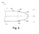
- FIG. 6 shows an alternative embodiment of an integrated air knife/silencer panel 300 as may be described herein.
- an air knife 310 may have a pair of side discharge gaps 320.
- the side discharge gaps 320 may be positioned just upstream of a pair of inwardly curved ends 330.
- the side discharge gaps 320 may similarly entrain the incoming air flow 20 and the bleed heat flow 90 into the entrained flow 210.
- Other components and other configurations may be used herein.
- discharge gaps may be positioned herein in stages. These discharge gaps may be controlled independently to maintain the maximum airflow velocity while the bleed heat flow 90 may vary. Moreover, the discharge gaps may be positioned elsewhere along the silencer panel 230.
- the use of the air knives 160 of the integrated air knife/silencer panels 250 thus entrains a large amount of the incoming airflow 20 with the bleed air 90 as the entrained flow 210 so as to decrease the pressure drop thereacross.
- the use of the integrated air knife/silencer panels 250 with the contoured shape 260 also may aid in reducing the airflow pressure drop. Overall gas turbine efficiency and output therefore may be increased.
- the air knifes 160 also provide overall pressure and temperature uniformity. Moreover, the air knives 160 may generate less noise than known impingement or other types of bleed heat systems.
- the air knives 160 also should have a long component lifetime given the lack of moving parts therein. For syngas based turbines, the inlet airflow rate may be decreased due to the heating effect for increased efficiency given a decrease in the over bleed airflow.
Applications Claiming Priority (1)
| Application Number | Priority Date | Filing Date | Title |
|---|---|---|---|
| US13/669,478 US9157333B2 (en) | 2012-11-06 | 2012-11-06 | Inlet bleed heat system with integrated air knife/silencer panels |
Publications (1)
| Publication Number | Publication Date |
|---|---|
| EP2728143A2 true EP2728143A2 (en) | 2014-05-07 |
Family
ID=49517404
Family Applications (1)
| Application Number | Title | Priority Date | Filing Date |
|---|---|---|---|
| EP13191626.4A Withdrawn EP2728143A2 (en) | 2012-11-06 | 2013-11-05 | Inlet bleed heat system with integrated air knife/siliencer panels |
Country Status (4)
| Country | Link |
|---|---|
| US (1) | US9157333B2 (ja) |
| EP (1) | EP2728143A2 (ja) |
| JP (1) | JP2014092157A (ja) |
| CN (1) | CN203962214U (ja) |
Cited By (1)
| Publication number | Priority date | Publication date | Assignee | Title |
|---|---|---|---|---|
| CN114320606A (zh) * | 2021-12-13 | 2022-04-12 | 中国船舶重工集团公司第七0三研究所 | 一种自动调节的h-25燃气轮机发电机组ibh装置 |
Families Citing this family (10)
| Publication number | Priority date | Publication date | Assignee | Title |
|---|---|---|---|---|
| US9551282B2 (en) | 2014-10-17 | 2017-01-24 | General Electric Company | Media pads with mist elimination features |
| US9771865B2 (en) * | 2014-10-28 | 2017-09-26 | General Electric Company | Inlet bleed heat manifold including acoustically treated feed pipe |
| US9890713B2 (en) * | 2015-03-04 | 2018-02-13 | General Electric Company | Heavy duty gas turbine inlet system |
| US10704464B2 (en) | 2016-02-16 | 2020-07-07 | General Electric Company | Acoustic nozzles for inlet bleed heat systems |
| US10273881B2 (en) * | 2016-04-06 | 2019-04-30 | General Electric Company | Foreign object damage screen for gas turbine system |
| US20170292456A1 (en) * | 2016-04-12 | 2017-10-12 | General Electric Company | Integrated gas turbine inlet silencer and bleed heat system |
| US10260418B2 (en) | 2017-03-20 | 2019-04-16 | General Electric Company | Evaporative cooling systems and methods |
| US10495000B2 (en) | 2017-03-20 | 2019-12-03 | General Electric Company | Contoured evaporative cooling medium |
| US10260421B2 (en) | 2017-03-20 | 2019-04-16 | General Electric Company | Fibrous media drift eliminator |
| US10669935B2 (en) * | 2018-04-17 | 2020-06-02 | Sammy Kayara | Wind-funneling for gas turbines |
Family Cites Families (22)
| Publication number | Priority date | Publication date | Assignee | Title |
|---|---|---|---|---|
| US2663993A (en) * | 1945-10-10 | 1953-12-29 | Westinghouse Electric Corp | Deicing apparatus |
| US3572960A (en) * | 1969-01-02 | 1971-03-30 | Gen Electric | Reduction of sound in gas turbine engines |
| JPS5045503U (ja) * | 1973-08-27 | 1975-05-08 | ||
| US6004095A (en) * | 1996-06-10 | 1999-12-21 | Massachusetts Institute Of Technology | Reduction of turbomachinery noise |
| US5974802A (en) | 1997-01-27 | 1999-11-02 | Alliedsignal Inc. | Exhaust gas recirculation system employing a fluidic pump |
| US6027304A (en) | 1998-05-27 | 2000-02-22 | General Electric Co. | High pressure inlet bleed heat system for the compressor of a turbine |
| US6260658B1 (en) * | 1998-10-23 | 2001-07-17 | Donaldson Company, Inc. | Silencer for a gas turbine |
| WO2004101975A1 (de) * | 2003-05-15 | 2004-11-25 | Alstom Technology Ltd | Vorrichtung zur schalldämpfung in einem strömungskanal |
| FR2857699B1 (fr) * | 2003-07-17 | 2007-06-29 | Snecma Moteurs | Dispositif de degivrage pour aube de roue directrice d'entree de turbomachine, aube dotee d'un tel dispositif de degivrage, et moteur d'aeronef equipe de telles aubes |
| US7549282B2 (en) | 2005-10-25 | 2009-06-23 | General Electric Company | Multi-slot inter-turbine duct assembly for use in a turbine engine |
| GB2451261B (en) | 2007-07-25 | 2011-08-24 | Anthony Gregory Smith | Gas turbine engine nozzle |
| KR100940788B1 (ko) | 2007-10-26 | 2010-02-10 | 김영훈 | 반도체소자 제조설비의 배기덕트용 배기활성장치 |
| US8312726B2 (en) | 2007-12-21 | 2012-11-20 | United Technologies Corp. | Gas turbine engine systems involving I-beam struts |
| US8001789B2 (en) * | 2008-03-26 | 2011-08-23 | Alstom Technologies Ltd., Llc | Utilizing inlet bleed heat to improve mixing and engine turndown |
| EP2119891B1 (en) * | 2008-05-15 | 2023-09-13 | Mitsubishi Heavy Industries, Ltd. | Control of working fluid flow of a two-shaft gas turbine |
| CN201241751Y (zh) | 2008-08-12 | 2009-05-20 | 路兴荣 | 发动机进气增压装置 |
| US20100205967A1 (en) | 2009-02-16 | 2010-08-19 | General Electric Company | Pre-heating gas turbine inlet air using an external fired heater and reducing overboard bleed in low-btu applications |
| US8083466B2 (en) | 2009-03-13 | 2011-12-27 | General Electric Company | Turbomachine inlet heating system |
| US8647057B2 (en) | 2009-06-02 | 2014-02-11 | Siemens Energy, Inc. | Turbine exhaust diffuser with a gas jet producing a coanda effect flow control |
| CH701236A1 (de) * | 2009-06-09 | 2010-12-15 | Alstom Technology Ltd | Vorrichtung zur Schalldämpfung in einem Strömungskanal einer Gasturbine, welche Vorrichtung Zuführungselemente für rezirkulierte Abgase in den Ansaugluftstrom aufweist. |
| US8196907B2 (en) | 2009-08-18 | 2012-06-12 | General Electric Company | System for conditioning the airflow entering a turbomachine |
| US8272222B2 (en) * | 2010-01-04 | 2012-09-25 | General Electric Company | Inlet bleed heat system with ejector/mixer nozzles for noise reduction |
-
2012
- 2012-11-06 US US13/669,478 patent/US9157333B2/en not_active Expired - Fee Related
-
2013
- 2013-10-30 JP JP2013224824A patent/JP2014092157A/ja active Pending
- 2013-11-05 EP EP13191626.4A patent/EP2728143A2/en not_active Withdrawn
- 2013-11-06 CN CN201320697810.8U patent/CN203962214U/zh not_active Expired - Fee Related
Non-Patent Citations (1)
| Title |
|---|
| None |
Cited By (1)
| Publication number | Priority date | Publication date | Assignee | Title |
|---|---|---|---|---|
| CN114320606A (zh) * | 2021-12-13 | 2022-04-12 | 中国船舶重工集团公司第七0三研究所 | 一种自动调节的h-25燃气轮机发电机组ibh装置 |
Also Published As
| Publication number | Publication date |
|---|---|
| US20140123674A1 (en) | 2014-05-08 |
| CN203962214U (zh) | 2014-11-26 |
| JP2014092157A (ja) | 2014-05-19 |
| US9157333B2 (en) | 2015-10-13 |
Similar Documents
| Publication | Publication Date | Title |
|---|---|---|
| US9157333B2 (en) | Inlet bleed heat system with integrated air knife/silencer panels | |
| US9085996B2 (en) | System for managing exhaust flow for a gas turbine | |
| US20190153938A1 (en) | Gas turbine blower/pump | |
| US10066632B2 (en) | Inlet bleed heat control system | |
| JP5638301B2 (ja) | ガスタービン燃焼器のためのシステム及び方法 | |
| CA2811818C (en) | High bleed flow muffling system | |
| JP6431725B2 (ja) | ガスタービンエンジン吸気スクリーンを除氷し、吸気エアフィルタを除湿するためのシステムおよび方法 | |
| EP1731734A3 (en) | Counterrotating turbofan engine | |
| EP2354493A2 (en) | Ejector/mixer nozzle for noise reduction | |
| US20150322861A1 (en) | Enhanced Turbine Cooling System Using a Blend of Compressor Bleed Air and Ambient Air | |
| EP3064742B1 (en) | Heavy duty gas turbine inlet system | |
| US9644496B2 (en) | Radial diffuser exhaust system | |
| US9097136B2 (en) | Contoured honeycomb seal for turbine shroud | |
| US20140321967A1 (en) | Gas Turbine Power Augmentation System | |
| CN107448293B (zh) | 用于燃气涡轮发动机的排气扩压器 | |
| US20130170962A1 (en) | Forward Step Honeycomb Seal for Turbine Shroud | |
| JP2017020505A (ja) | ガスタービン出力増大システム | |
| JP2015214978A (ja) | 圧縮機吐出空気とタービン区画空気との混合物を用いる強化されたタービン冷却システム | |
| US20170234239A1 (en) | Acoustic Nozzles for Inlet Bleed Heat Systems | |
| RU2495269C2 (ru) | Способ работы компрессорного воздушно-реактивного двигателя | |
| EP3418525A1 (en) | Backflow prevention system for a gas turbine engine | |
| US9441540B2 (en) | Inducer guide vanes | |
| KR20120055520A (ko) | 다축 다단 제트엔진 |
Legal Events
| Date | Code | Title | Description |
|---|---|---|---|
| PUAI | Public reference made under article 153(3) epc to a published international application that has entered the european phase |
Free format text: ORIGINAL CODE: 0009012 |
|
| 17P | Request for examination filed |
Effective date: 20131105 |
|
| AK | Designated contracting states |
Kind code of ref document: A2 Designated state(s): AL AT BE BG CH CY CZ DE DK EE ES FI FR GB GR HR HU IE IS IT LI LT LU LV MC MK MT NL NO PL PT RO RS SE SI SK SM TR |
|
| AX | Request for extension of the european patent |
Extension state: BA ME |
|
| STAA | Information on the status of an ep patent application or granted ep patent |
Free format text: STATUS: THE APPLICATION IS DEEMED TO BE WITHDRAWN |
|
| 18D | Application deemed to be withdrawn |
Effective date: 20180602 |