EP2728089B1 - Sequenced chamber wave generator controller and method - Google Patents
Sequenced chamber wave generator controller and method Download PDFInfo
- Publication number
- EP2728089B1 EP2728089B1 EP13190442.7A EP13190442A EP2728089B1 EP 2728089 B1 EP2728089 B1 EP 2728089B1 EP 13190442 A EP13190442 A EP 13190442A EP 2728089 B1 EP2728089 B1 EP 2728089B1
- Authority
- EP
- European Patent Office
- Prior art keywords
- wave
- chambers
- chamber
- pool
- controller
- Prior art date
- Legal status (The legal status is an assumption and is not a legal conclusion. Google has not performed a legal analysis and makes no representation as to the accuracy of the status listed.)
- Active
Links
Images


Classifications
-
- A—HUMAN NECESSITIES
- A63—SPORTS; GAMES; AMUSEMENTS
- A63G—MERRY-GO-ROUNDS; SWINGS; ROCKING-HORSES; CHUTES; SWITCHBACKS; SIMILAR DEVICES FOR PUBLIC AMUSEMENT
- A63G31/00—Amusement arrangements
- A63G31/007—Amusement arrangements involving water
-
- E—FIXED CONSTRUCTIONS
- E04—BUILDING
- E04H—BUILDINGS OR LIKE STRUCTURES FOR PARTICULAR PURPOSES; SWIMMING OR SPLASH BATHS OR POOLS; MASTS; FENCING; TENTS OR CANOPIES, IN GENERAL
- E04H4/00—Swimming or splash baths or pools
- E04H4/0006—Devices for producing waves in swimming pools
-
- G—PHYSICS
- G06—COMPUTING OR CALCULATING; COUNTING
- G06F—ELECTRIC DIGITAL DATA PROCESSING
- G06F3/00—Input arrangements for transferring data to be processed into a form capable of being handled by the computer; Output arrangements for transferring data from processing unit to output unit, e.g. interface arrangements
- G06F3/01—Input arrangements or combined input and output arrangements for interaction between user and computer
- G06F3/048—Interaction techniques based on graphical user interfaces [GUI]
- G06F3/0481—Interaction techniques based on graphical user interfaces [GUI] based on specific properties of the displayed interaction object or a metaphor-based environment, e.g. interaction with desktop elements like windows or icons, or assisted by a cursor's changing behaviour or appearance
- G06F3/04817—Interaction techniques based on graphical user interfaces [GUI] based on specific properties of the displayed interaction object or a metaphor-based environment, e.g. interaction with desktop elements like windows or icons, or assisted by a cursor's changing behaviour or appearance using icons
-
- G—PHYSICS
- G06—COMPUTING OR CALCULATING; COUNTING
- G06F—ELECTRIC DIGITAL DATA PROCESSING
- G06F3/00—Input arrangements for transferring data to be processed into a form capable of being handled by the computer; Output arrangements for transferring data from processing unit to output unit, e.g. interface arrangements
- G06F3/01—Input arrangements or combined input and output arrangements for interaction between user and computer
- G06F3/048—Interaction techniques based on graphical user interfaces [GUI]
- G06F3/0481—Interaction techniques based on graphical user interfaces [GUI] based on specific properties of the displayed interaction object or a metaphor-based environment, e.g. interaction with desktop elements like windows or icons, or assisted by a cursor's changing behaviour or appearance
- G06F3/0482—Interaction with lists of selectable items, e.g. menus
-
- G—PHYSICS
- G06—COMPUTING OR CALCULATING; COUNTING
- G06F—ELECTRIC DIGITAL DATA PROCESSING
- G06F3/00—Input arrangements for transferring data to be processed into a form capable of being handled by the computer; Output arrangements for transferring data from processing unit to output unit, e.g. interface arrangements
- G06F3/01—Input arrangements or combined input and output arrangements for interaction between user and computer
- G06F3/048—Interaction techniques based on graphical user interfaces [GUI]
- G06F3/0484—Interaction techniques based on graphical user interfaces [GUI] for the control of specific functions or operations, e.g. selecting or manipulating an object, an image or a displayed text element, setting a parameter value or selecting a range
- G06F3/04842—Selection of displayed objects or displayed text elements
-
- G—PHYSICS
- G06—COMPUTING OR CALCULATING; COUNTING
- G06F—ELECTRIC DIGITAL DATA PROCESSING
- G06F3/00—Input arrangements for transferring data to be processed into a form capable of being handled by the computer; Output arrangements for transferring data from processing unit to output unit, e.g. interface arrangements
- G06F3/01—Input arrangements or combined input and output arrangements for interaction between user and computer
- G06F3/048—Interaction techniques based on graphical user interfaces [GUI]
- G06F3/0484—Interaction techniques based on graphical user interfaces [GUI] for the control of specific functions or operations, e.g. selecting or manipulating an object, an image or a displayed text element, setting a parameter value or selecting a range
- G06F3/04847—Interaction techniques to control parameter settings, e.g. interaction with sliders or dials
-
- G—PHYSICS
- G06—COMPUTING OR CALCULATING; COUNTING
- G06F—ELECTRIC DIGITAL DATA PROCESSING
- G06F3/00—Input arrangements for transferring data to be processed into a form capable of being handled by the computer; Output arrangements for transferring data from processing unit to output unit, e.g. interface arrangements
- G06F3/01—Input arrangements or combined input and output arrangements for interaction between user and computer
- G06F3/048—Interaction techniques based on graphical user interfaces [GUI]
- G06F3/0484—Interaction techniques based on graphical user interfaces [GUI] for the control of specific functions or operations, e.g. selecting or manipulating an object, an image or a displayed text element, setting a parameter value or selecting a range
- G06F3/0486—Drag-and-drop
-
- A—HUMAN NECESSITIES
- A63—SPORTS; GAMES; AMUSEMENTS
- A63B—APPARATUS FOR PHYSICAL TRAINING, GYMNASTICS, SWIMMING, CLIMBING, OR FENCING; BALL GAMES; TRAINING EQUIPMENT
- A63B69/00—Training appliances or apparatus for special sports
- A63B69/0093—Training appliances or apparatus for special sports for surfing, i.e. without a sail; for skate or snow boarding
-
- B—PERFORMING OPERATIONS; TRANSPORTING
- B63—SHIPS OR OTHER WATERBORNE VESSELS; RELATED EQUIPMENT
- B63B—SHIPS OR OTHER WATERBORNE VESSELS; EQUIPMENT FOR SHIPPING
- B63B34/00—Vessels specially adapted for water sports or leisure; Body-supporting devices specially adapted for water sports or leisure
- B63B34/70—Arrangements on vessels specially adapted for generating waves for surfing, wakeboarding or the like, e.g. ballast tanks
Definitions
- the present application relates to wave generators, such as, for example, wave generators for making waves in pools for recreational purposes.
- Wave generators are often used for recreational purposes. Wave generators create one or more waves in a pool or the like, and people typically either play in the waves or use the waves for aquatic sports such as board sports. Aquatic board sports, such as surfing and bodyboarding, require that the waves be rideable. Enthusiasts in these types of sports often use wave generators for competition, practice and entertainment.
- Existing wave generators typically use wave generating chambers to produce a wave that travels in a direction where the peak of the wave is substantially parallel to the chambers and the beach as it travels from the chambers toward the beach to the wave generating apparatus, and the wave is produced when the wave generating chambers (either one chamber or multiple chambers) are all activated simultaneously, resulting in the water being pushed away from the wave generating chambers, which then travels at an angle away from the chambers. The wave then travels away from the chamber until it reaches the opposite end of the pool, breaking at some point between the wave generating chamber and the opposite end of the pool.
- the waves that are created from these chambers however, always require single or multiple chambers to actuate simultaneously in unison.
- Japan App. No. 04-037314 JPO Publication No. 05-202626 discloses a pool that produce waves that travel in a perpendicular direction from one side toward the other side of the pool.
- the side walls of the pool are in a fan shape to allow persons to ride the wave longer and avoid hitting the wall.
- This apparatus only produces single waves that travel perpendicularly away from generating apparatus until the wave reaches the opposite end of the pool, and does not teach sequencing. That apparatus attempts to provide for a longer ride on the wave by simply angling the walls in a fan shape, but does not compensate for the wave losing amplitude and strength.
- a caisson wave generator for generating high quality surfing waves includes pressure means in the form of a mechanical plunger that moves vertically within the caisson and is controlled by hydraulic rams that move the plunger using a controlling computer or PLC electronics.
- a software interface allows the preferred wave profile to be specified.
- What is needed is an apparatus that overcomes the shortcomings of the prior art, including providing an apparatus that can create a variety of rideable waves, and further providing the rider the ability to customize the wave characteristics - including size, shape, and pattern.
- an aquatic sports amusement apparatus that includes a pool, a plurality of wave generating chambers that communicate with the pool so as to release water into the pool and a mobile application controller that operates the chambers, such that each chamber in the plurality releases water to create waves.
- the controller is connected to the plurality of chambers via a network connection, such a connection could include a local area network, a wireless network, the internet and a virtual private network.
- the controller could be at a distant location from the pool and chamber complex, and the controller may be a smart phone, personal computer, personal digital assistant, laptop and tablet computer.
- the controller also has a graphical user interface (GUI) with a wave creation module, and maybe a wave ride module and a viewing module. Through these modules, users can create wave profiles and graphically model these wave profiles before actually creating the wave. The wave profiles can be shared with others.
- GUI may also allow the user to video capture the wave, and then allow the user to view and share that video with others.
- the system can also have a scheduling module to ensure that the controller operation of the chambers is based on a single wave profile at a time. This further allows a user to create a wave profile, save that profile, schedule a time to create and ride a wave based on that profile. This minimizes the user's dissatisfaction in waiting for the wave machine to be available, while maximizing the use of the wave machine with fewer down periods.
- the water valve 24 may be closed during the initial air fill phase to create a larger air volume in the chamber which, when released, creates a larger depression in the pool.
- air valve 26 can rapidly supply pressurized air to the chamber after the chamber is filled with water to push water out and amplify the wave peak. This process of pushing water out of the chamber and into the pool is known as releasing water.
- vent valve 28 may be connected to a vacuum source such as a vacuum pump, or may be a vent outlet connected via suitable valving either to atmosphere or to a vacuum source.
- the wave is created by a surging motion in the pool 50 that changes the characteristics of the waves to create a considerably hollow barreling wave.
- the flow of water created by the sequence resembles a diamond pattern and additional patterns would resemble diamonds linked at the vertices. This pattern effectively reduces the depth of the water in the pool 50 between successive waves, which cause the waves to pitch away from the chambers and create a considerably hollow barrel, as seen in FIG. 8 .
- This type of sequencing can produce waves where the peak of the wave is substantially parallel to the chambers 54 and the beach 42 as it travels from the chambers 54 toward the beach 42.
- the pattern of the waves may resemble diamonds from a top view, and additional patterns may resemble diamonds linked at the vertices.
- the diamond effect is a result of the multiple wave segments generated in the sequence.
- This diamond pattern 125 creates a surging motion 115 in the entire pool 50 due to the sequence creating multiple waves 105, 110.
- the surging motion changes the breaking characteristics of waves' natural flow. Indeed, the diamond pattern 125 reduces the depth of the water between successive waves because the previous wave will push the water away from the chambers 54 and towards the beach end 42. This causes waves to pitch away from the chambers 54 and create a considerably hollow barrel 120. Additionally, the surge 115 interacts with the wave 110 near the end of its break, which increases the wave height or amplitude, just as backwash interacts with waves in the ocean.
- a chamber 54 Immediately after a chamber 54 is activated, it creates a trough in the body of water 52 by allowing the water to enter the chamber space 56. The trough is created outside of the chamber 54 where the water entered the chamber 54. When the chamber 54 pushes or releases the water out to create a wave, the water flows into the area previously vacated and is now a trough. The sequencing allows the wave to travel not substantially perpendicular to the chamber 54 and break to create a wave.
- the controller operates the sequenced fashion or sequencing, which comprises each chamber in the plurality actuating after a delay and completing a chamber period.
- the fraction of the chamber period that is used as the delay by the controller 62 is approximately between 0.75 and 0.10.
- the amount of delay in the sequence can be adjusted within this range to adjust the amplitude of the wave and the direction the peak may travel. Also, the delay may vary between adjacent chambers.
- the amplitude or height of the peak of the wave created generally depends on the size of the wave generating apparatus.
- the peak traveling in direction A has an amplitude of nearly twice that of the peak traveling perpendicular to the chambers 54 in direction C.
- the peak of the wave may increase as it builds through the first few chambers in the sequence until it reaches its maximum height. For example, using chambers 54 that are 150 cubic feet, the wave reaches about six feet in height.
- a wave without sequencing that travels in a direction perpendicular to the wave generating chambers 54, in direction C may reach a height of about three feet.
- step 1615 the system enters the wave creation module 1611 and proceeds to step 1615.
- the details for this step will be discussed below with reference to FIGS. 17-19 .
- he user at step 1615 may select a previously saved profile or a shared profile to modify.
- the user may also select a preset profile that the system may offer, and modify that profile. This is discussed in greater detail below. Since this is a system where multiple devices can be used, the user may have created a wave profile on his personal computer and saved that profile, however, when he arrives at that wave generating facility he may want to make some final tweaks to the wave profile on this smart phone. The system allows for this flexibility.
- the user After creating the wave profile, the user has the option at step 1620 to have the application render a computer model of the wave profile to fully visualize what the wave will look like (see step 1620). This is an optional, but preferable step in the system.
- the user then may choose to modify the wave profile by returning to step 1615 or save the wave profile at step 1630.
- the system may then ask at step 1635 whether the user would like to share this profile with another, and if the user so desires, the user would enter the email address or other identifying information at step 1640 such that the system can transmit the wave profile to that third party.
- the system would then request whether the user would like to create another wave profile at step 1645, and if so the user is returned to step 1615, otherwise the user may return to step 1610, or may simply log out.
- the system enters the wave ride module and the user must then select which wave he would like to ride at step 1675.
- the user must also select or determine the wave generating facility on which the selected wave will be produced and ridden. This is shown at step 1680, and may be accomplished by a number of ways including a pull down menu on the mobile application controller. Another non-limiting example is that the mobile application controller could use GPS or the network identification codes to automatically determine which facility is closest and use that facility as the one to create the wave.
- the user may also at this time schedule a time with the wave generating facility so that he does not needlessly wait for his opportunity to ride the wave.
- the present wave profile of blocks 1820 provide instructions to actuate first chamber 1, then after a delay chamber 2, then after a delay chamber 3, then after a delay chamber 4 and finally after a delay chamber 5. And each actuation of each chamber is of the same magnitude.
- the user may then choose to add other chambers to actuate. For example, on a smartphone application this may entail touching an icon of a block1825 and dragging it (as shown by arrow 1830) to an appropriate location to actuate chamber 6. After making these selections, the user may view a computer rendering of the wave profile at step 1620.
- FIG. 19 illustrates that not only can the user add new chamber actuations, but the user can also move, modify and delete existing chamber actuations.
- the user as shown in FIG 19 starts with a profile shown by the gray blocks, with chambers 1 and 9 actuating simultaneously, then after a delay chambers 8 and 2 actuating simultaneously, then after a delay chambers 7 and 3 actuating simultaneously, then after a delay chambers 6 and 4 actuating simultaneously and finally after a delay chamber 5 actuating.
- the user may choose to delay the actuation of chamber 9 by moving the block along the arrow labeled 1905.
- the user also chooses to delay the actuation of chamber 8 by moving the block along the arrow labeled 1910.
- the user also shortens the length of the actuation block of chamber 8 (shown at position 1915) so chamber 8 will not expel as much water.
- the user also desires to add an actuation of chamber 7 with the same magnitude as that of chamber 8 as shown at position 1920.
- the user adds a larger magnitude actuation of chamber 6 at position 1925.
- the interface may accomplish these movements, modifications and deletions by allowing the user to drag existing actuations blocks to new locations, and by allowing a user to modify the magnitude of a block by touching that block on the screen and setting the size (with the size of zero representing a deletion). After making these selections, the user may view a computer rendering of the wave profile at step 1620.
Landscapes
- Engineering & Computer Science (AREA)
- General Engineering & Computer Science (AREA)
- Theoretical Computer Science (AREA)
- Human Computer Interaction (AREA)
- Physics & Mathematics (AREA)
- General Physics & Mathematics (AREA)
- Architecture (AREA)
- Structural Engineering (AREA)
- Civil Engineering (AREA)
- Other Liquid Machine Or Engine Such As Wave Power Use (AREA)
- Structures Of Non-Positive Displacement Pumps (AREA)
- Revetment (AREA)
- Studio Devices (AREA)
- Time Recorders, Dirve Recorders, Access Control (AREA)
- Fittings On The Vehicle Exterior For Carrying Loads, And Devices For Holding Or Mounting Articles (AREA)
- Control Of Position, Course, Altitude, Or Attitude Of Moving Bodies (AREA)
Description
- The present application relates to wave generators, such as, for example, wave generators for making waves in pools for recreational purposes.
- Wave generators are often used for recreational purposes. Wave generators create one or more waves in a pool or the like, and people typically either play in the waves or use the waves for aquatic sports such as board sports. Aquatic board sports, such as surfing and bodyboarding, require that the waves be rideable. Enthusiasts in these types of sports often use wave generators for competition, practice and entertainment.
- Existing wave generators typically use wave generating chambers to produce a wave that travels in a direction where the peak of the wave is substantially parallel to the chambers and the beach as it travels from the chambers toward the beach to the wave generating apparatus, and the wave is produced when the wave generating chambers (either one chamber or multiple chambers) are all activated simultaneously, resulting in the water being pushed away from the wave generating chambers, which then travels at an angle away from the chambers. The wave then travels away from the chamber until it reaches the opposite end of the pool, breaking at some point between the wave generating chamber and the opposite end of the pool. The waves that are created from these chambers, however, always require single or multiple chambers to actuate simultaneously in unison. The waves can only be ridden for only a short period of time and distance because after the wave is created, it begins to decrease in amplitude and quickly becomes unrideable. Japan App. No.
04-037314 05-202626 - Other types of wave generating pools use a high velocity sheet of water shot over a bed form in the shape of a wave. These are not "true" waves; rather water shaped into a wave. An example includes
U.S. Pat. No. 5,236,280 which discloses a "Sheet Flow Water Ride." There are several shortcoming with this prior art. First, a conventional surf board with fins cannot be used because the fins would extend too deeply into the sheet flow of water and touch the bed form underneath. Second, the bed form is static, such that only one type of "wave" can be produced. - From the international patent application published under the publication number
WO 2009/058031 A1 a caisson wave generator for generating high quality surfing waves is known that includes pressure means in the form of a mechanical plunger that moves vertically within the caisson and is controlled by hydraulic rams that move the plunger using a controlling computer or PLC electronics. A software interface allows the preferred wave profile to be specified. - From the United States patent
US 4,999,860 an aquatic sports amusement apparatus according to the precharacterizing part ofclaim 1 is known. - What is needed is an apparatus that overcomes the shortcomings of the prior art, including providing an apparatus that can create a variety of rideable waves, and further providing the rider the ability to customize the wave characteristics - including size, shape, and pattern.
- This and other objects are achieved by the aquatic sports amusement apparatus with the features in the characterizing part of
claim 1 and accordingly by a method of creating waves according toclaim 10 in the aquatic sports amusement apparatus according toclaim 1. Advantageous embodiments are claimed in the dependent claims 2 - 9 and 11 - 14. - What is provided herein is an aquatic sports amusement apparatus that includes a pool, a plurality of wave generating chambers that communicate with the pool so as to release water into the pool and a mobile application controller that operates the chambers, such that each chamber in the plurality releases water to create waves. The controller is connected to the plurality of chambers via a network connection, such a connection could include a local area network, a wireless network, the internet and a virtual private network. The controller could be at a distant location from the pool and chamber complex, and the controller may be a smart phone, personal computer, personal digital assistant, laptop and tablet computer.
- The controller also has a graphical user interface (GUI) with a wave creation module, and maybe a wave ride module and a viewing module. Through these modules, users can create wave profiles and graphically model these wave profiles before actually creating the wave. The wave profiles can be shared with others. The GUI may also allow the user to video capture the wave, and then allow the user to view and share that video with others.
- The system can also have a scheduling module to ensure that the controller operation of the chambers is based on a single wave profile at a time. This further allows a user to create a wave profile, save that profile, schedule a time to create and ride a wave based on that profile. This minimizes the user's dissatisfaction in waiting for the wave machine to be available, while maximizing the use of the wave machine with fewer down periods.
- Other aspects of the invention are disclosed herein as discussed in the following Drawings and Detailed Description.
- The invention can be better understood with reference to the following figures. The components within the figures are not necessarily to scale, emphasis instead being placed on clearly illustrating example aspects of the invention. In the figures, like reference numerals designate corresponding parts throughout the different views. It may be understood that certain components and details may not appear in the figures to assist in more clearly describing the invention.
-
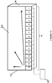
FIG. 1 is a top view of one example embodiment of a wave generator apparatus in a wave pool with sixteen chambers. -
FIG. 2 is a cross-section ofFIG. 1 , illustrating one example embodiment of a wave generating chamber in a wave pool. -
FIG. 2A is a schematic block diagram of a control system for controlling operation of the sequencing of delay between actuating each chamber in the apparatus inFIGS. 1-2 . -
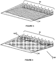
FIG. 3 is a top view of one example embodiment of a wave generator apparatus in a wave pool before any of the chambers have been actuated. -
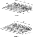
FIGS. 4-6 are top views of one example embodiment of a wave generator apparatus in a wave pool showing the chambers being actuated in sequence to generate waves. -
FIG. 7 is a top view of one example embodiment of a wave generator apparatus in a wave pool showing the diamond pattern created during the sequence with the diamond patterns linked at the vertices. -
FIG. 8 is a perspective view of one example embodiment of a wave generator apparatus in a wave pool showing a considerably hollow barrel wave pitching away from the chambers that is created from the surge effect. -
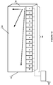
FIG. 9 is a top view of one example embodiment of a wave generator apparatus in a wave pool showing the direction that the wave may travel; -
FIGS. 10-11 are top views of one example embodiment of a wave generator apparatus in a wave pool showing multiple directions that the wave can flow depending on the amount of delay in the sequence; -
FIG. 12 is a view from the beach side or the side opposite the wave generating chambers of the pool. It shows the progression of the wave as it flows and how the height increases at various instances. -
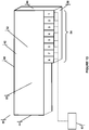
FIG. 13 is a top view of one example embodiment of a wave generator apparatus in a wave pool with the side wall extending beyond the wave generating chambers. -
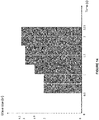
FIG. 14 is a graph showing the size of the wave and the amount of time it takes the wave to reach that size for a small-scale version of the apparatus with nine chambers. -
FIG. 15 illustrates the wave generator apparatus connected to a network along with mobile application controllers connected to the network. -
FIG. 16 is a flow chart that describes the method for controlling the wave generating apparatus from a mobile application controller. -
FIG. 17 illustrates an embodiment of the step for creating a wave profile. -
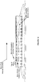
FIG. 18 illustrates an embodiment of the step for creating and modifying a wave profile. -
FIG. 19 illustrates an embodiment of the step for creating and modifying a wave profile. - Following is a non-limiting written description of example embodiments illustrating various aspects of the invention. These examples are provided to enable a person of ordinary skill in the art to practice the full scope of the invention without having to engage in an undue amount of experimentation. As may be apparent to persons skilled in the art, further modifications and adaptations can be made without departing from the scope of the invention, which is limited only by the claims.
- The apparatus disclosed herein in various example embodiments provides a sequenced-chamber wave-generating apparatus that may be adapted for use with aquatic board sports or any other suitable purpose, such as miniature modeling of wave formations. The apparatus overcomes the deficiencies in the prior art by creating a surging motion in the pool that changes the characteristics of the waves to create a considerably hollow barreling wave. The flow of water created by the presently-disclosed sequencing can resemble a diamond pattern and additional patterns such as diamonds linked at the vertices. These patterns effectively reduce the depth of the water between successive waves, which causes them to pitch away from the chambers and create a considerably hollow barrel. Additionally, the wave may travel in a direction that is not perpendicular to the wave generating apparatus such that the wave strength continues to be replenished as the waves move across the pool. These are only two examples of waves that the wave generator apparatus.
-
FIG. 1 illustrates an example embodiment of a wave generator apparatus, which comprises a pool orcontainer 50, a body ofwater 52, a plurality of wave generating chambers 54 (each chamber is individually numbered 1-16), and acontroller 62 to operate thechambers 54. In this example embodiment, there are sixteenwave generating chambers 54. Although there is no specifically required number of wave generating chambers 54 (other example embodiments include twenty-four and thirty-two chambers, for instance), toofew chambers 54 in the apparatus may not be able to produce sufficient resolution to create a wave that can be ridden. In one example embodiment, each chamber is 10 feet by 5 feet by 3 feet, giving each chamber a capacity of 150 cubic feet. Other example embodiments may have wave generating chambers as big as 260 cubic feet or more. It would be apparent to those skilled in the art to modify the size and water displacement of the chambers as needed for specific applications. - The
pool 50 may be rectangular shaped and holds the body ofwater 52. Thepool 50 has afirst end 58, asecond end 60, twosides floor 36. Thefirst end 58 is comprised of a plurality ofchambers 54 adjacent to one another and thesecond end 60 is at the opposite end of the pool where thebeach 42 is located. The twosides pool 50. Thefirst end 58,second end 60, and twosides pool 50 to contain the body ofwater 52 along with thefloor 36 that is under the body ofwater 52. The body ofwater 52 rests in thepool 50 and may be in a still state until thechambers 54 begin to actuate in sequence and create a wave using the body ofwater 52 in thepool 50. -
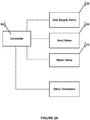
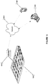
FIG. 2 illustrates an example embodiment of a singlewave generating chamber 54, which can comprise a chamber space 56 having aback wall 18, anupper wall 20, and a reflectingwall 22 at the rear wall of the pool that faces the body ofwater 52 in thepool 50. An example may be that ofU.S. Pat. No. 7,815,396 to McFarland , the same inventor of the present application. Apassageway 30 at the lower end ofwall 22 allows communication of water between thechamber 54 and the body ofwater 52 in the pool. A mechanical two-way valve 24 may be located inpassageway 30. - The
chambers 54 may be connected to an air supply throughinlet valve 26 located close to the upper end of the chamber backwall 18 and is also connected to avent valve 28 in the upper wall 32, which may be connected to a vacuum pump. Thefloor 36 of the pool may have a first, upwardlyinclined portion 38 extending frompassageway 30 away from thewave reflecting wall 22, a generallyflat portion 40, and an upwardly inclined portion orbeach 42 at the opposite,second end 60 of thepool 50. - In operation of this example embodiment, the
chamber 54 is first filled with air throughvalve 26, thereby displacing water into thepool 50.Valve 26 is then closed and the chamber air is vented suddenly throughvent valve 28, causing thewater 52 to flow from thepool 50 throughpassageway 30 into the now empty space 56 in thechamber 54. The water level in pool drops suddenly, creating a depression or trough in the water that reflects against the back orwave reflecting wall 22 of thepool 50. This creates a circulating motion of the water, which is enhanced by the design of theback wall 22. Thevent valve 28 in the air chamber is shut at the proper time to prevent immediate water resurgence back into thepool 50, which enhances the second trough behind the peak. The mechanical two-way valve 24 can also be used to prevent immediate resurgence. Thewater valve 24 may be closed during the initial air fill phase to create a larger air volume in the chamber which, when released, creates a larger depression in the pool. Alternatively,air valve 26 can rapidly supply pressurized air to the chamber after the chamber is filled with water to push water out and amplify the wave peak. This process of pushing water out of the chamber and into the pool is known as releasing water. Alternatively, ventvalve 28 may be connected to a vacuum source such as a vacuum pump, or may be a vent outlet connected via suitable valving either to atmosphere or to a vacuum source. - As illustrated schematically in
FIG. 2A , theelectronic controller 62 may be electrically connected with thevalves controller 62 may control this operation for each chamber, such that thecontroller 62 actuates each of the chambers in sequence. Thecontroller 62 may begin by actuating the first chamber or the first set of chambers in the plurality. After a predetermined delay, thecontroller 62 actuates the second chamber or second set of chambers in the plurality, and, after another predetermined delay, actuates the third chamber or third set of chambers in the plurality. This may continue for a fourth chamber or fourth set of chambers, or any number of additional chambers or set of chambers. Thecontroller 62 continues actuating each chamber in the plurality after a delay.FIG. 2A illustrates that thecontroller 62 controls the valves in each chamber so that after actuating the first chamber or first set of chambers, it can control the valves in that chamber or set of chambers and, after a delay, actuate the second chamber or second set of chambers and control its valves. Thecontroller 62 can actuate each chamber in sequence after a delay and control the valves. - The wave generator apparatus has the ability to create waves where the peak of the wave travels in a direction where the peak of the wave is substantially parallel to the
chambers 54 and thebeach 42 as it travels from thechambers 54 toward thebeach 42. The peak of the wave is defined as the highest water level in the pool. The direction the peak travels is the path that the peak of the wave flows during the life of the wave. - To create the wave, the
controller 62 may actuate thechambers 54 in a sequence with a delay between actuating each chamber or set ofchambers 54, as described above. The delay is approximately a fraction of the chamber period. In the present example embodiment a seen inFIGS. 3-6 , nine chambers 1-9 are used to produce a wave that can be ridden where the peak of the wave is substantially parallel to thechambers 54 and thebeach 54 as it travels from thechambers 54 toward thebeach 42. - The wave is created by a surging motion in the
pool 50 that changes the characteristics of the waves to create a considerably hollow barreling wave. As seen inFIG. 7 , the flow of water created by the sequence resembles a diamond pattern and additional patterns would resemble diamonds linked at the vertices. This pattern effectively reduces the depth of the water in thepool 50 between successive waves, which cause the waves to pitch away from the chambers and create a considerably hollow barrel, as seen inFIG. 8 . - By way of example, the sequence may begin with
chambers 54 on the edges of the pool to initiate thefirst wave segment 105 shown inFIG. 4 . Chambers 1-2 and 8-9 actuate to begin the sequence. After the delay, asecond wave segment 110 shown inFIG. 5 is generated in the sequence from center chambers between the edge segments (i.e., actuating chambers 3-7). The sequence continues to actuate the chambers to generate the first and second wave segment steps using the same delay. Therefore, the chambers operate in sequence, not all in unison. - This sequence creates the surging
effect 115 in thepool 50 that creates barreling waves that are more hollow, i.e., the barrel-shapedwave 120 preferred by wave riding enthusiasts, as seen inFIG. 8 . In other embodiments, the sequence can begin with the inner chambers and continue with the outer chambers. For example, the sequence may begin withchambers 54 in the center of the pool initiating a first wave segment. Chambers 3-7 could actuate to begin the sequence. After the delay, a second wave segment may be generated in the sequence from both sides of the first, center wave segment. This could be chambers 1-2 and 8-9. After a delay of the same or similar length, a third wave segment could be generated in the sequence from chambers 3-7, for instance. In either example embodiment, the sequence may continue to actuate the chambers to generate the second and third wave segment steps using the same or similar delay. Also, each segment can be produced by a single chamber or two or more chambers, and the sequence can include more than two segments. - Moreover, when multiple
adjacent chambers 54 actuate during each segment, there can be a secondary delay for each chamber. For instance, using the example sequence seen inFIGS. 4-5 , during segment one, chambers 1-2 and 8-9 will all actuate using the primary delay, but with the secondary delay, they do not have to all actuate simultaneously. The secondary delay can actuatechambers chambers - This type of sequencing can produce waves where the peak of the wave is substantially parallel to the
chambers 54 and thebeach 42 as it travels from thechambers 54 toward thebeach 42. As seen inFIG. 7 , the pattern of the waves may resemble diamonds from a top view, and additional patterns may resemble diamonds linked at the vertices. The diamond effect is a result of the multiple wave segments generated in the sequence. Thisdiamond pattern 125 creates a surgingmotion 115 in theentire pool 50 due to the sequence creatingmultiple waves diamond pattern 125 reduces the depth of the water between successive waves because the previous wave will push the water away from thechambers 54 and towards thebeach end 42. This causes waves to pitch away from thechambers 54 and create a considerablyhollow barrel 120. Additionally, thesurge 115 interacts with thewave 110 near the end of its break, which increases the wave height or amplitude, just as backwash interacts with waves in the ocean. - The fraction of delay between actuating each
chamber 54 or set of chambers may be proportional to the chamber period. The chamber period is the time it takes a chamber to release the water and refill to the predetermined level. To refill, thechamber 54 may permit a fixed amount of water, if any, to reenter thechamber 54. When a chamber completes its period, the chamber is prepared to actuate again. To produce waves where the peak of the wave is substantially parallel to thechambers 54 and thebeach 42 as it travels from thechambers 54 toward thebeach 42, the controller operation may actuate eachchamber 54 or set of chambers, using a delay, in sequenced fashion. For example, just after the first segment (first chamber or first set of chambers) completes the wave production portion of its period, thecontroller 62 may actuate the second segment (second chamber or second set of chambers), and it begins its period. This sequence may be repeated with each segment (chamber or set of chambers) using the same or similar delay, with thecontroller 62 operating the sequencing. - The
controller 62 operates the sequenced fashion or sequencing, which comprises each chamber in the plurality actuating after a delay and completing a chamber period. The chamber period that is used as the delay by thecontroller 62 may be approximately one chamber period. The amount of delay in the sequence can be adjusted to as low as 0.10 of a chamber period to adjust the amplitude of the wave and the direction the peak may travel. The delay may be more than one chamber period. Also, the delay may vary between adjacent chambers. - When a
chamber 54 or set of chambers has completed the process of pushing out the water or air needed to create a wave (for example, after half of the entire chamber period), the subsequent chamber or set of chambers can activate in the sequence. This allows the waves to continue to flow and create a surging effect. For example, in the example embodiment shown inFIGS. 4-5 , each chamber period may be completed in two seconds. Therefore, the delay in the sequence would be set at one second, which is half of the chamber period. When each segment is completed, a new wave segment is then produced in sequence. While this example uses half of the chamber period as the delay in the sequence, similar sequences may be created with timing delays that are sequenced to actuate achamber 54 or set of chambers during or soon after the previous chamber's or set of chambers' period. - The amplitude or height of the
peak 130 of thewave 110 created generally depends on the size of the wave generating apparatus. However, the surge that is created using the present system increases the height of the wave over other designs because thesurge 115 interacts with thewave 110 near the end of its break, as shown inFIG. 8 , e.g. barreling perspective view following the sequence inFIG. 6 . This interaction pushes the wave up to create a higher, bigger wave that tends to have desirable barreling characteristics. - The wave generator apparatus has the ability to create waves where the peak of the wave travels in a direction that is not substantially perpendicular to the ends of the pool and the chambers, as illustrated in
FIG. 9 . The peak of the wave is defined as the highest water level in the pool. The direction the peak travels is the path that the peak of the wave flows during the life of the wave. Although the wave may reach thebeach end 42 of the pool opposite the chambers, the wave peak may continue to travel in a direction that is not perpendicular to thechambers 54. - To create a wave where the peak travels in a direction that is not substantially perpendicular to the
chambers 54, thecontroller 62 may actuate thechambers 54 in a sequence with a delay between actuating each chamber, as described above. The delay is approximately a fraction of the chamber period. In the present example embodiment, sixteen chambers 1-16 are used to produce a wave that can be ridden and the peak travels not substantially perpendicular to thechambers 54 in direction A. - The sequence starts with
chamber 1 and continues sequentially (in lowest to highest numerical order of the chambers) down the plurality of chambers, which determines the direction of the wave. The wave breaks nearly right out of the chamber, and the break of the wave allows the peak to travel in a direction not substantially perpendicular to the chambers. Thus, a rider is able to ride the wave over much of the pool's water surface area. The peak continues until it reaches theside 44 of thepool 50. Although the path that the peak of the wave travels is not exactly parallel to thechambers 54, the pool may be constructed such that the peak may reach theside wall 44 before the peak could reach the opposite, beach end 42 of the pool. As each chamber actuates, the apparatus replenishes the wave to continue its momentum such that the wave can continue to be ridden. - Immediately after a
chamber 54 is activated, it creates a trough in the body ofwater 52 by allowing the water to enter the chamber space 56. The trough is created outside of thechamber 54 where the water entered thechamber 54. When thechamber 54 pushes or releases the water out to create a wave, the water flows into the area previously vacated and is now a trough. The sequencing allows the wave to travel not substantially perpendicular to thechamber 54 and break to create a wave. - The fraction of delay between actuating each chamber may be proportional to the chamber period. The chamber period is the time it takes a chamber to release the water and refill to the predetermined level. To refill, the
chamber 54 may permit a fixed amount of water, if any, to reenter thechamber 54. When a chamber completes its period, the chamber is prepared to actuate again. To create a peak that travels not substantially perpendicular to thechambers 54, in A direction, the controller operation may actuate each chamber, using a delay, in sequenced fashion. For example, whilechamber 1 is in the wave production portion of its period, thecontroller 62 actuateschamber 2 and it begins its period. This sequence is repeated with each chamber using the same delay, with thecontroller 62 operating the sequencing. - The controller operates the sequenced fashion or sequencing, which comprises each chamber in the plurality actuating after a delay and completing a chamber period. The fraction of the chamber period that is used as the delay by the
controller 62 is approximately between 0.75 and 0.10. The amount of delay in the sequence can be adjusted within this range to adjust the amplitude of the wave and the direction the peak may travel. Also, the delay may vary between adjacent chambers. - By way of example only, a delay of 0.25 can create a wave traveling in direction A as illustrated in
FIG. 9 . The 0.25 delay means that thecontroller 62 may actuatechamber 2 whenchamber 1 has completed 0.25 of its chamber period. Likewise, thecontroller 62 may actuatechamber 3 whenchamber 2 has completed 0.25 of its chamber period. This delay may continue in the entire sequence. - When a
chamber 54 is half of the way completed with the process of pushing out the water or air needed to create a wave (i.e., 0.25 of the entire chamber period), the subsequent chamber can activate in the sequence. This allows the wave to continue in the desired direction A. For example, in the example embodiment inFIG. 9 , each chamber period is completed in four seconds. Therefore, the delay in the sequence would be set at one second, which is 0.25 of the chamber period. When the entire sequence is completed, a new wave can then be produced using the same sequence. While this example uses 0.25 of the chamber period as the delay in the sequence, similar waves can be created with timing delays that are sequenced to actuate achamber 54 when theprevious chamber 54 is in the process of the wave generating phase of the chamber period. - The amplitude or height of the peak of the wave created generally depends on the size of the wave generating apparatus. However, using this sequencing method, the peak traveling in direction A has an amplitude of nearly twice that of the peak traveling perpendicular to the
chambers 54 in direction C. The peak of the wave may increase as it builds through the first few chambers in the sequence until it reaches its maximum height. For example, usingchambers 54 that are 150 cubic feet, the wave reaches about six feet in height. Conversely, a wave without sequencing that travels in a direction perpendicular to thewave generating chambers 54, in direction C, may reach a height of about three feet. - For example, using a small version of the wave generating apparatus with only nine chamber yielded the results presented in
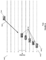
FIG. 14 . When a sequence with 0.25 delay is performed, a trough is created at 0.5 seconds, and the wave dramatically starts to build at 0.75 seconds, which is roughly when the third chamber is actuated. The wave has a peak of 2 inches at this point, which is a dramatic increase from 0.5 seconds when the wave size was 0 inches. At about 1.25 seconds, the wave starts to crest just past the third chamber, when the peak reaches 2.5 inches. The wave's peak heightens to 3 inches when it reaches the fourth chamber. This occurs at 1.5 seconds, which coincides with when the sixth chamber is actuated by thecontroller 62. At 2 seconds, the peak reaches its maximum height of 3.2 inches. Conversely, a wave traveling perpendicular to thechambers 54 has a maximum peak height of only 2 inches. - As illustrated in
FIG. 12 , the wave increases in height as it continues to flow and thechambers 54 continue to push the wave. The wave size increases as a result of eachchamber 54 releasing water into the pool, which pushes into the same piece of wave, causing it to amplify. The same piece of wave is pushed when the each chamber actuates. This process continues through the beginning portion of the sequence or first few chambers until the wave reaches its maximum height. If there are toofew chambers 54, the wave may not be smooth enough to ride. Likewise, if thechambers 54 produce a wave too big, it may be too choppy and not smooth enough to ride. - The direction of the peak is determined by the delay in the sequencing of the chambers.
FIG. 10 illustrates the different directions the peak can travel depending on the delay between the chambers. For example, if there is no delay and eachchamber 54 actuates at the same time, the peak may travel perpendicular to the chambers in direction C towards thebeach 42. When thecontroller 62 uses sequencing for a delay between eachchamber 54, the peak may travel in more of an angled direction in order of the sequence. Here, inFIG. 10 , the sequence starts withchamber 1 actuating, thenchamber 2, thenchamber 3, and continuing down the plurality ofchambers 54 untilchamber 16 actuates. The peak may flow towardsside 44 when this sequence continues. - An increase in the delay sequence may cause the peak to travel in a direction that is more angled towards
side 44. For example, a shortened delay in the sequence would result in the peak traveling in direction B, which flows more towardsside 44. When increasing the delay even more, the peak can travel not substantially perpendicular to thechambers 54 towardsside 44 in direction A - As illustrated in
FIG. 11 , the peak can also travel in the other direction towardsside 46. To do so, the sequence would have to start atchamber 16 and end atchamber 1. A shortened delay between thecontroller 62 actuating the chambers may result in the peak traveling in somewhat of an angle towardsside 46, in direction E. A longer delay between thecontroller 62 actuating the chambers can result in the peak traveling not substantially perpendicular to the chambers in direction D, towardsside 46. Also,chambers Fig. 11 ) and one moving in direction A (Fig. 10 ). -
FIG. 13 illustrates an example embodiment where thepool 52 extends beyond thechambers 54. This allows the wave to continue to travel after the sequence is complete, thus allowing a rider more time to ride the created wave. - As discussed above, the wave generator can produce a variety of waves because the sequencing of the individual chambers by the controller. The controller has until now been described as residing at the wave generator facility. This however need not be the case. The wave generator apparatus may actually be controlled by the user through a mobile application controller. The mobile application controller may be used on a variety platforms, such as smartphones (e.g., iPhone, Droid, etc.), tablets (e.g., iPad, Nexus, etc.), laptops, personal digital assistants and personal computers. Referring to
FIG. 15 , thecontroller 1510 of thewave generator apparatus 1505 may be connected to the internet, local area network ("LAN"), virtual private network,wireless network 1515, andmobile application controllers wave generator apparatus 1505. By providingmobile application controllers wave generator apparatus 1505 through the internet orLAN 1515, produce the actual wave and rider that wave. Never before has a user been able to create a wave and ride that wave. Now they can. - In one embodiment, the interface on the mobile application controller may include a custom wave profile creator. The user may customize the lag between the chambers of the wave generator apparatus, the actuation of chambers, the sequence of actuation, and experiment with different wave creations. The interface may also include a wave modeling screen such that the user can see what the customized wave profile would look like prior to communicating the wave profile to controller 1410 and producing an actual wave on the wave generator apparatus 1405. The user, therefore, can create precisely the wave he desires. Moreover, the user can save the customized wave profiles, such that when the user arrives at the wave generator apparatus, the user can select that wave profile, execute the profile on the apparatus and ride the wave. Alternatively, he user can create a wave profile and actuate the wave generator apparatus remotely for someone else to ride. Imagine, creating a custom wave and having a professional surfer ride your creation.
- One embodiment of the system is shown in
Fig. 16 . In thefirst step 1605, the user can enter a username and password so as to retrieve previous wave profiles and videos the user has made. The login step is preferably, but optional. After login, the user is asked atstep 1610 what action he would like to take: enter thewave creation module 1611 to create a wave, enter theviewing module 1612 to view a wave video/photograph or enter thewave ride module 1613 to ride a wave. - If the user selects create a wave profile, the system enters the
wave creation module 1611 and proceeds to step 1615. The details for this step will be discussed below with reference toFIGS. 17-19 . It should further be noted that he user atstep 1615 may select a previously saved profile or a shared profile to modify. The user may also select a preset profile that the system may offer, and modify that profile. This is discussed in greater detail below. Since this is a system where multiple devices can be used, the user may have created a wave profile on his personal computer and saved that profile, however, when he arrives at that wave generating facility he may want to make some final tweaks to the wave profile on this smart phone. The system allows for this flexibility. After creating the wave profile, the user has the option atstep 1620 to have the application render a computer model of the wave profile to fully visualize what the wave will look like (see step 1620). This is an optional, but preferable step in the system. The user then may choose to modify the wave profile by returning to step 1615 or save the wave profile atstep 1630. The system may then ask atstep 1635 whether the user would like to share this profile with another, and if the user so desires, the user would enter the email address or other identifying information atstep 1640 such that the system can transmit the wave profile to that third party. The system would then request whether the user would like to create another wave profile atstep 1645, and if so the user is returned tostep 1615, otherwise the user may return to step 1610, or may simply log out. - If the user selects at
step 1610 to view a video, the system enters theviewing module 1612 and the user must then select which video he would like to view atstep 1650. These videos could include videos taken of the user riding a particular wave, or video of third parties riding waves that have been shared with the user. After viewing the video, the system may then asks atstep 1660 whether the user would like to share this video with another, and if the user so desires, the user would enter the email address or other identifying information atstep 1665 such that the system can transmit the wave video to that third party. Optionally, the system can allow users to assign sharing rights, such that a video from a third party cannot be shared if that third party so chooses. The system would then request whether the user would like to view another wave video atstep 1670, and if so the user is returned tostep 1650, otherwise the user may return to step 1610, or may simply log out. It should be noted that the language used herein is a video, however, it would be apparent to those skilled in the art that still frame photographs could be captured and used in the system. - If the user selects at
step 1610 to ride a wave, the system enters the wave ride module and the user must then select which wave he would like to ride atstep 1675. The user must also select or determine the wave generating facility on which the selected wave will be produced and ridden. This is shown atstep 1680, and may be accomplished by a number of ways including a pull down menu on the mobile application controller. Another non-limiting example is that the mobile application controller could use GPS or the network identification codes to automatically determine which facility is closest and use that facility as the one to create the wave. Atstep 1682, the user may also at this time schedule a time with the wave generating facility so that he does not needlessly wait for his opportunity to ride the wave. After selecting the wave, the user may optionally be asked whether he would like to have the ride videotaped (or photographed) atstep 1685. If so, the user should then determine which camera or cameras should be used. For example, the wave generator facility may have cameras available and the user's mobile application controller may also have a camera. After selecting the cameras the user may then actuate the wave generator apparatus based on the selected wave profile. Then the system would associate the wave profile with the video or photographs and post those videos for later viewing and/or sharing atsteps step 1699, and if so the user is returned tostep 1675, otherwise the user may return to step 1610, or may simply log out. - It should be noted, that the wave profile can be transmitted and actuated by a user that is remote to the wave generating facility. This feature could be used, for example, to allow surfing fans to create waves for professional surfers to ride. The fan could see the wave ride in real time. There are countless promotional activities that can be realized using this user defined, remotely actuated, custom wave creation. It should also be noted that it is not intended that the modules and steps detailed above be in precisely the order described. The order detailed is simply to illustrate the various features of the system.
- Turning now to
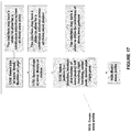
FIG. 17 , the steps in creating the wave profile will be discussed. In one embodiment, the system may allow the user to select only three attributes of the wave profile - i.e., (1) size, (2) shape, and (3) pattern (i.e., location/direction and peak number). For example atstep 1705, the user would select the size of the wave from small, medium or large. Then at step 1710 the used selects the shape of the wave: mushy or hollow. And finally atstep 1715 the user selects the pattern of the wave (i.e., direction, location and number of wave peaks): left traveling, right traveling, center peak, double peak, triple peak. Each of these selections may be discrete, but the graphical user interface of the system may provide a slider such that these selections are more continuous across a range. After making these selections, the user may view a computer rendering of the wave profile atstep 1620. -
FIG. 18 provides a more complex interface that a user may use to create a wave profile. The user may for example, select a present wave profile or may use the interface describe with reference toFIG 17 to create a wave profile. The interface could then represent that wave profile on a twodimensional graph 1805 with the chamber numbers on one axis 1810 and time on theother axis 1815. The wave profile may be represented as a number ofblocks 1820 wherein the left size of the block represents the time along the time axis when that particular chamber is actuated, and the length of the block is the magnitude of the water expelled by that particular chamber. So the present wave profile ofblocks 1820 provide instructions to actuatefirst chamber 1, then after adelay chamber 2, then after adelay chamber 3, then after adelay chamber 4 and finally after adelay chamber 5. And each actuation of each chamber is of the same magnitude. The user may then choose to add other chambers to actuate. For example, on a smartphone application this may entail touching an icon of a block1825 and dragging it (as shown by arrow 1830) to an appropriate location to actuatechamber 6. After making these selections, the user may view a computer rendering of the wave profile atstep 1620. -
FIG. 19 illustrates that not only can the user add new chamber actuations, but the user can also move, modify and delete existing chamber actuations. Again, the user as shown inFIG 19 starts with a profile shown by the gray blocks, withchambers delay chambers delay chambers delay chambers delay chamber 5 actuating. The user may choose to delay the actuation ofchamber 9 by moving the block along the arrow labeled 1905. The user also chooses to delay the actuation ofchamber 8 by moving the block along the arrow labeled 1910. The user also shortens the length of the actuation block of chamber 8 (shown at position 1915) sochamber 8 will not expel as much water. The user also desires to add an actuation ofchamber 7 with the same magnitude as that ofchamber 8 as shown atposition 1920. Finally the user adds a larger magnitude actuation ofchamber 6 atposition 1925. The interface may accomplish these movements, modifications and deletions by allowing the user to drag existing actuations blocks to new locations, and by allowing a user to modify the magnitude of a block by touching that block on the screen and setting the size (with the size of zero representing a deletion). After making these selections, the user may view a computer rendering of the wave profile atstep 1620. - As described above, several users can share their wave profiles. For example, if a professional surfer creates a particular wave profile, other can following in their footsteps and attempt to ride that wave. This creates a community of surfers and promotes competition that is very alive in the surfing community. Users can also attempt to improve upon wave profiles that have been shared.
- The system may also have a scheduling module such that a user can create and submit a particular wave profile and schedule a time to ride that wave. This is shown in
FIG. 16 step 1682. This minimizes the user's dissatisfaction in waiting for the wave machine to be available, while maximizing the use of the wave machine with fewer down periods. - The above description of the disclosed example embodiments is provided to enable any person skilled in the art to make or use the invention. Various modifications to these example embodiments will be readily apparent to those skilled in the art. Thus, it is to be understood that the description and drawings presented herein represent a presently preferred example embodiment of the invention and are therefore representative of the subject matter which is broadly contemplated by the present invention.
Claims (14)
- An aquatic sports amusement apparatus, comprising:a pool (50);a plurality of wave generating chambers (54) that communicate with the pool (50) so as to release water into the pool (50);each of the plurality of chambers (54) having a valve structure (24,26,28), wherein each valve structure (24,26,28) is connected to an application controller (62) wherein the connection is constructed to allow for the actuation of each valve structure (24,26,28) independently of the other valve structures (24,26,28); andwherein the controller is configured to perform the following chamber control steps:a. actuating the valve structure (24,26,28) of a first chamber (54) or valve structures (24,26,28) of a first set of chambers (54) in the plurality to release water into the pool (50), during step (a) the valve structure (24,26,28) of a second chamber (54) or the valve structures (24,26,28) of a second set of chambers (54) of the plurality are actuated so as to prevent the release water into the pool (50); andb. after a delay, actuating the valve structure (24,26,28) of the second chamber (54) or the valve structures (24,26,28) of the second set of chambers (54) in the plurality to release water into the pool (50);wherein the release of water into the pool (50) creates a wave (110) that can be ridden by a user;characterized in thatthe application controller (62, 1520, 1525) is a mobile application controller (62, 1520, 1525) that connects to the plurality of chambers (54) via a network connection (1515) and further has a graphical user interface that further comprises a wave creation module (1611) adapted to create a wave profile; andwherein the mobile application controller (62) is electrically connected with the valve structure (24,26,28) in order to control their operation by first filling the chamber (54) with air through a gas supply valve (26), thereby displacing water into the pool (50), then closing the gas supply valve (26) and then venting the chamber air suddenly through a vent valve (28), causing the water (52) to flow from the pool (50) through passageway (30) into the now empty space (56) in the chamber (54).
- The apparatus of claim 1, wherein the network connection (1515) is selected from a group consisting of a local area network, a wireless network, the internet and a virtual private network.
- The apparatus of claim 1, wherein the pool (50) and chambers (54) are located at one location and the controller (62) is at least partially located at a second location, wherein the first location and second location are separated by at least 1.61 km (1 mile).
- The apparatus of claim 1, wherein the controller (62) is selected from a group consisting of a smart phone, personal computer, personal digital assistant, laptop and tablet computer.
- The apparatus of claim 1, wherein the graphical user interface is further adapted to graphically model a wave profile (1620).
- The apparatus of claim 1, wherein the wave creation module (1611) is adapted to share the wave profile (1635) with a specified entity.
- The apparatus of claim 1, wherein the controller (62) is a computing device that comprises a graphical user interface that is adapted to capture data (1685) selected from the group consisting of video, audio and photographs.
- The apparatus of claim 1, wherein the controller (62) is a computing device that comprises a graphical user interface that is adapted to share data (1660) selected from the group consisting of video, audio and photographs with a specified entity.
- The apparatus of claim 1, wherein the controller (62) is a computing device that comprises a graphical user interface that further comprises a wave ride module (1613) wherein a user selects a wave profile (1675) and the controller (62) operation of the chambers (54) is based on the wave profile (1675).
- A method of creating a rideable wave (110) in the aquatic sports amusement apparatus according to claim 1, the method comprising:a. providing an aquatic sports amusement apparatus according to claim 1 comprising the mobile application controller (1520, 1525) that operates the chambers (54) such that each chamber (54) in the plurality releases water to create waves, the controller (1520, 1525) further having the graphical user interface (GUI), the graphical user interface further comprises a wave creation module (1611) adapted to create a wave profile;b. creating a wave profile on the graphical user interface (1615);c. actuating a first chamber (54) or first set of chambers (54) in the plurality to release water into the pool (50) based on the wave profile;d. during step (b) actuating a second chamber (54) or second set of chambers (54) in the plurality to prevent the release water into the pool (50) based on the wave profile; ande. after a delay, actuating the second chamber (54) or second set of chambers (54) in the plurality to release water into the pool (50) based on the wave profile.
- The method of claim 10 wherein the graphical user interface is operated by dragging and dropping icons, the method further comprising:
dragging and dropping icons (1830) as part of creating the wave profile. - The method of claim 10 wherein the graphical user interface represents the chambers as icons and the icons can be moved along an axis of time, the method further comprising:moving the icons (1905) along the time axis to create a particular sequence for actuations of the chambers;creating a wave profile based on the sequence.
- The method of claim 10, wherein the step of creating a wave profile further comprises:
generating a graphical model (1620) of the wave based on the wave profile. - The method of claim 13, wherein the step of creating a wave profile further comprises;
modifying the wave profile (1625) after generating the graphical model.
Applications Claiming Priority (2)
| Application Number | Priority Date | Filing Date | Title |
|---|---|---|---|
| US201261721304P | 2012-11-01 | 2012-11-01 | |
| US13/740,419 US9103133B2 (en) | 2012-11-01 | 2013-01-14 | Sequenced chamber wave generator controller and method |
Publications (3)
| Publication Number | Publication Date |
|---|---|
| EP2728089A2 EP2728089A2 (en) | 2014-05-07 |
| EP2728089A3 EP2728089A3 (en) | 2017-08-09 |
| EP2728089B1 true EP2728089B1 (en) | 2020-09-09 |
Family
ID=49513760
Family Applications (1)
| Application Number | Title | Priority Date | Filing Date |
|---|---|---|---|
| EP13190442.7A Active EP2728089B1 (en) | 2012-11-01 | 2013-10-28 | Sequenced chamber wave generator controller and method |
Country Status (3)
| Country | Link |
|---|---|
| US (7) | US9103133B2 (en) |
| EP (1) | EP2728089B1 (en) |
| ES (1) | ES2820512T3 (en) |
Cited By (1)
| Publication number | Priority date | Publication date | Assignee | Title |
|---|---|---|---|---|
| WO2024119282A1 (en) * | 2022-12-09 | 2024-06-13 | Whitewater West Industries Ltd. | Caisson height profiler system and method |
Families Citing this family (20)
| Publication number | Priority date | Publication date | Assignee | Title |
|---|---|---|---|---|
| EP2707558B1 (en) * | 2011-05-04 | 2017-10-11 | Stagger Reef Pte. Ltd. | Wave pool and method for producing periodic waves in such a wave pool |
| US11478719B2 (en) * | 2012-11-01 | 2022-10-25 | American Wave Machines, Inc. | Sequenced chamber wave generator controller and method |
| US9454829B2 (en) * | 2013-03-14 | 2016-09-27 | Google Technology Holdings LLC | Systems and methods for obtaining a digital wallpaper |
| USD879795S1 (en) * | 2016-06-07 | 2020-03-31 | Amadeus S.A.S. | Display screen with graphical user interface |
| JP7083520B2 (en) | 2016-11-08 | 2022-06-13 | カアナ ウェーブ カンパニー インコーポレイテッド | Wave-making method and equipment |
| US10119285B2 (en) | 2017-01-20 | 2018-11-06 | The Wave Pool Company, LLC | Systems and methods for generating waves |
| US10738492B1 (en) * | 2019-03-02 | 2020-08-11 | American Wave Machines, Inc. | Aquatic sports amusement apparatus |
| CN110056215B (en) * | 2019-04-25 | 2021-02-12 | 中国科学院电工研究所 | Interactive artificial wave making device and method |
| KR102378608B1 (en) * | 2020-01-07 | 2022-03-24 | 김기태 | A wave generating system |
| FR3106500A1 (en) * | 2020-01-28 | 2021-07-30 | Laurent HEQUILY | Installation with dynamic artificial waves for surfing |
| US10760290B1 (en) | 2020-02-10 | 2020-09-01 | Walter Judson Bennett | Plunger wave making apparatus |
| BR112022019731A2 (en) | 2020-02-14 | 2022-10-25 | Whitewater West Ind Ltd | WAVE GENERATOR IN POOL |
| US12404688B2 (en) | 2020-05-18 | 2025-09-02 | Whitewater West Industries Ltd. | Return channel for a surf pool |
| EP4153827A4 (en) | 2020-05-18 | 2024-07-17 | Whitewater West Industries Ltd | Pool wave generator |
| US12486685B2 (en) | 2021-01-25 | 2025-12-02 | Walter Judson Bennett | Diverging and converging swells to make surfing waves |
| CN119434716B (en) * | 2021-02-25 | 2026-01-27 | 白水西部工业有限公司 | Chamber and control system and method for generating waves |
| US12448800B2 (en) | 2022-10-19 | 2025-10-21 | Whitewater West Industries Ltd. | Butterfly fan inlet and chamber exhaust valve controllers for wave making system |
| AU2023394119A1 (en) * | 2022-12-12 | 2025-06-19 | Whitewater West Industries Ltd. | Adaptive experience and wave generation |
| EP4618060A1 (en) | 2024-03-13 | 2025-09-17 | Instant Sport, S.L. | Method and system for customising a surf session. |
| DE102024118798A1 (en) * | 2024-07-02 | 2026-01-08 | Unit Surf Pool Gmbh | Device and method for generating a surfable wave |
Family Cites Families (46)
| Publication number | Priority date | Publication date | Assignee | Title |
|---|---|---|---|---|
| US2406413A (en) | 1941-11-29 | 1946-08-27 | Skiles E Test | Terraced combination pool and reservoir |
| US3105456A (en) | 1954-08-09 | 1963-10-01 | Aerojet General Co | Pressure wave generator |
| US3350724A (en) | 1964-07-07 | 1967-11-07 | Walter J Leigh | Method and apparatus for generating artificial waves in a body of water |
| US3474334A (en) | 1965-10-07 | 1969-10-21 | Hewlett Packard Yokogawa | Automatic nulling measurement bridge using double phase angle detection |
| FR1580805A (en) | 1967-03-08 | 1969-09-12 | ||
| US3473334A (en) | 1968-06-24 | 1969-10-21 | Phillip Dexter | Apparatus and method for producing waves |
| US3629877A (en) | 1969-08-07 | 1971-12-28 | Siegfried A Schuster | Method and apparatus for wave formation in swim pools |
| US3913332A (en) | 1973-08-30 | 1975-10-21 | Arnold H Forsman | Continuous wave surfing facility |
| US4062192A (en) | 1974-06-03 | 1977-12-13 | Offshore Technology Corporation | Method of and mechanism for generating waves suitable for surfing |
| US4276664A (en) | 1979-01-30 | 1981-07-07 | Baker William H | Apparatus for wave-making |
| NL8203906A (en) | 1982-10-08 | 1984-05-01 | Handelsmaatschappij Edoch B V | PNEUMATIC WAVE GENERATOR. |
| US4558474A (en) | 1982-10-08 | 1985-12-17 | Ecopool Design Limited | Wave generator |
| US4522535A (en) | 1983-08-08 | 1985-06-11 | Ecopool Design Limited | Surf wave generator |
| US4515500A (en) * | 1983-11-15 | 1985-05-07 | Ecopool Design Limited | Combustion powered wave generator |
| US4730807A (en) | 1983-11-30 | 1988-03-15 | Wavetek International, Inc. | Surf pool gate valve |
| FR2564534A1 (en) * | 1984-05-21 | 1985-11-22 | Lahlou Jean Claude | Pneumatic device for producing waves in a liquid medium and process for its application |
| USRE34407E (en) | 1984-11-22 | 1993-10-12 | Light Wave, Ltd. | Water sports apparatus |
| EP0182923B1 (en) * | 1984-11-22 | 1987-09-23 | Otto Frenzl | Appliance for practising aquatic sports |
| GB8805480D0 (en) | 1988-03-08 | 1988-04-07 | Chutter G P | Apparatus for generating waves in swimming pool |
| US4692949A (en) * | 1985-12-11 | 1987-09-15 | Wavetek International, Inc. | High-head, low-volume surfing wave pool |
| US4730355A (en) | 1986-05-08 | 1988-03-15 | Kreinbihl Mark L | Pneumatic wave generator employing four-way valve arrangement |
| US5236280A (en) | 1987-05-27 | 1993-08-17 | Blade Loch, Inc. | Method and apparatus for improving sheet flow water rides |
| US4812077A (en) | 1987-12-17 | 1989-03-14 | The Great Wave Company, Inc. | Pneumatic/hydraulic wave generator |
| US4979244A (en) * | 1988-05-23 | 1990-12-25 | Dirk Bastenhof | Wave valve |
| US5098222A (en) | 1989-10-02 | 1992-03-24 | Wet Design | Wave generator |
| JPH0437314A (en) | 1990-06-01 | 1992-02-07 | Mitsubishi Electric Corp | Frequency division circuit |
| CA2081381C (en) | 1991-02-14 | 2000-06-20 | Alan Keith Vowles | Wave energy generator |
| US5186578A (en) | 1991-09-20 | 1993-02-16 | Space Biospheres Venture | Wave generator |
| JP3035056B2 (en) | 1992-01-28 | 2000-04-17 | 三菱重工業株式会社 | Wave pool |
| US5342145A (en) | 1993-04-21 | 1994-08-30 | Cohen Albert D | System for producing surfing waves for tube riding or wind surfing |
| US5833393A (en) | 1995-03-30 | 1998-11-10 | Carnahan; Richard P. | Wave cannon |
| US5535702A (en) | 1995-04-03 | 1996-07-16 | Idbeis; Badr | Aquarium sea current generator |
| US7091948B2 (en) * | 1997-04-25 | 2006-08-15 | Immersion Corporation | Design of force sensations for haptic feedback computer interfaces |
| US6256625B1 (en) * | 1998-09-15 | 2001-07-03 | National Instruments Corporation | Video acquisition system including objects with dynamic communication capabilities |
| US6475095B1 (en) | 1999-08-06 | 2002-11-05 | Nbgs International, Inc. | Amusement park water lock system and method of use |
| DE60029133T2 (en) | 1999-12-13 | 2007-01-11 | Kerry Peter Black | wave CONSTRUCTION |
| WO2002039862A1 (en) | 2000-11-16 | 2002-05-23 | Lochtefeld Thomas J | Method and apparatus for a wave pools |
| US6729799B1 (en) | 2001-09-28 | 2004-05-04 | George W. Raike | Pneumatic wave generator |
| BRPI0309828A2 (en) | 2002-05-02 | 2016-08-09 | Surf Pools Ltd | apparatus and method for the control of wave characteristics |
| US6920651B2 (en) | 2003-06-05 | 2005-07-26 | Michael Kevin Roberts | Surfing ring wave pool for generating multiple simultaneous endless traveling waves looping around a center island |
| US6964069B2 (en) | 2003-12-11 | 2005-11-15 | Anthony Thomas English | Floating wave making apparatus |
| US7815396B2 (en) | 2006-10-04 | 2010-10-19 | American Wave Machines, Inc. | Reflecting wave generator apparatus and method |
| WO2009058031A1 (en) * | 2007-10-30 | 2009-05-07 | Kerry Peter Black | Improvements in and relating to wave generation |
| DE102008057785A1 (en) * | 2008-11-17 | 2010-05-20 | Action Team Veranstaltungs Gmbh | Artificial surfing facility |
| US8644960B2 (en) * | 2010-10-22 | 2014-02-04 | Gecko Alliance Group Inc. | Method and system for providing ambiance settings in a bathing system |
| EP2707558B1 (en) | 2011-05-04 | 2017-10-11 | Stagger Reef Pte. Ltd. | Wave pool and method for producing periodic waves in such a wave pool |
-
2013
- 2013-01-14 US US13/740,419 patent/US9103133B2/en not_active Ceased
- 2013-10-28 ES ES13190442T patent/ES2820512T3/en active Active
- 2013-10-28 EP EP13190442.7A patent/EP2728089B1/en active Active
-
2015
- 2015-07-24 US US14/808,076 patent/US10145135B2/en active Active
-
2017
- 2017-08-09 US US15/672,759 patent/USRE47023E1/en active Active
-
2018
- 2018-10-01 US US16/149,051 patent/US10280640B2/en active Active
-
2019
- 2019-05-02 US US16/402,070 patent/US10612256B2/en active Active
-
2020
- 2020-02-19 US US16/795,492 patent/US11131107B2/en active Active
-
2021
- 2021-09-03 US US17/467,042 patent/US11660546B2/en active Active
Non-Patent Citations (1)
| Title |
|---|
| None * |
Cited By (3)
| Publication number | Priority date | Publication date | Assignee | Title |
|---|---|---|---|---|
| WO2024119282A1 (en) * | 2022-12-09 | 2024-06-13 | Whitewater West Industries Ltd. | Caisson height profiler system and method |
| US12180738B2 (en) | 2022-12-09 | 2024-12-31 | Whitewater West Industries Ltd. | Caisson height profiler system and method |
| US12540479B2 (en) | 2022-12-09 | 2026-02-03 | Whitewater West Industries Ltd. | Caisson height profiler system and method |
Also Published As
| Publication number | Publication date |
|---|---|
| US10612256B2 (en) | 2020-04-07 |
| US20190257101A1 (en) | 2019-08-22 |
| US10280640B2 (en) | 2019-05-07 |
| ES2820512T3 (en) | 2021-04-21 |
| EP2728089A3 (en) | 2017-08-09 |
| EP2728089A2 (en) | 2014-05-07 |
| US20210396029A1 (en) | 2021-12-23 |
| USRE47023E1 (en) | 2018-09-04 |
| US9103133B2 (en) | 2015-08-11 |
| US20190032350A1 (en) | 2019-01-31 |
| US11660546B2 (en) | 2023-05-30 |
| US20150330093A1 (en) | 2015-11-19 |
| US20200181929A1 (en) | 2020-06-11 |
| US11131107B2 (en) | 2021-09-28 |
| US20140115770A1 (en) | 2014-05-01 |
| US10145135B2 (en) | 2018-12-04 |
Similar Documents
| Publication | Publication Date | Title |
|---|---|---|
| US11660546B2 (en) | Sequenced chamber wave generator controller and method | |
| US12029990B2 (en) | Sequenced chamber wave generator controller and method | |
| JP6875535B2 (en) | Information processing methods and devices, storage media, electronic devices | |
| JP6783395B2 (en) | Information processing methods and devices, storage media, electronic devices | |
| EP2634327B1 (en) | Sequenced chamber wave generator apparatus and method | |
| CN111566651A (en) | Virtual/Augmented Reality Modeling Applications for Architecture | |
| CN110147231A (en) | Combine special efficacy generation method, device and storage medium | |
| CA3185238C (en) | Sequenced chamber wave generator controller and method | |
| Xu et al. | A procedural method for irregular tree models | |
| JP7403632B2 (en) | Enhanced granule effect | |
| CN118370983A (en) | Interactive control method and device for game, electronic equipment and readable storage medium | |
| CN117122928A (en) | Particle animation display methods, devices, equipment, media and program products | |
| CN113119626B (en) | Method and system for making 3D (three-dimensional) book | |
| CN120837933A (en) | A shooting control method and related device for a virtual character | |
| KR20260019933A (en) | System for creating pet avatars | |
| Hoyle | Compsci 94 Fall 2013 | |
| Ginslov | 10 Temporal Scaffolding | |
| CN107679376A (en) | A kind of mobile terminal dynamic unlocking method, mobile terminal and storage medium |
Legal Events
| Date | Code | Title | Description |
|---|---|---|---|
| PUAI | Public reference made under article 153(3) epc to a published international application that has entered the european phase |
Free format text: ORIGINAL CODE: 0009012 |
|
| 17P | Request for examination filed |
Effective date: 20131028 |
|
| AK | Designated contracting states |
Kind code of ref document: A2 Designated state(s): AL AT BE BG CH CY CZ DE DK EE ES FI FR GB GR HR HU IE IS IT LI LT LU LV MC MK MT NL NO PL PT RO RS SE SI SK SM TR |
|
| AX | Request for extension of the european patent |
Extension state: BA ME |
|
| PUAL | Search report despatched |
Free format text: ORIGINAL CODE: 0009013 |
|
| AK | Designated contracting states |
Kind code of ref document: A3 Designated state(s): AL AT BE BG CH CY CZ DE DK EE ES FI FR GB GR HR HU IE IS IT LI LT LU LV MC MK MT NL NO PL PT RO RS SE SI SK SM TR |
|
| AX | Request for extension of the european patent |
Extension state: BA ME |
|
| RIC1 | Information provided on ipc code assigned before grant |
Ipc: A63G 31/00 20060101ALI20170704BHEP Ipc: E04H 4/00 20060101AFI20170704BHEP Ipc: A63B 69/00 20060101ALI20170704BHEP Ipc: B63B 35/85 20060101ALI20170704BHEP |
|
| STAA | Information on the status of an ep patent application or granted ep patent |
Free format text: STATUS: REQUEST FOR EXAMINATION WAS MADE |
|
| 17P | Request for examination filed |
Effective date: 20180208 |
|
| RBV | Designated contracting states (corrected) |
Designated state(s): AL AT BE BG CH CY CZ DE DK EE ES FI FR GB GR HR HU IE IS IT LI LT LU LV MC MK MT NL NO PL PT RO RS SE SI SK SM TR |
|
| STAA | Information on the status of an ep patent application or granted ep patent |
Free format text: STATUS: EXAMINATION IS IN PROGRESS |
|
| 17Q | First examination report despatched |
Effective date: 20181004 |
|
| GRAP | Despatch of communication of intention to grant a patent |
Free format text: ORIGINAL CODE: EPIDOSNIGR1 |
|
| STAA | Information on the status of an ep patent application or granted ep patent |
Free format text: STATUS: GRANT OF PATENT IS INTENDED |
|
| RIC1 | Information provided on ipc code assigned before grant |
Ipc: A63B 69/00 20060101ALI20200311BHEP Ipc: E04H 4/00 20060101AFI20200311BHEP Ipc: A63G 31/00 20060101ALI20200311BHEP Ipc: B63B 34/70 20200101ALI20200311BHEP |
|
| INTG | Intention to grant announced |
Effective date: 20200407 |
|
| GRAS | Grant fee paid |
Free format text: ORIGINAL CODE: EPIDOSNIGR3 |
|
| GRAA | (expected) grant |
Free format text: ORIGINAL CODE: 0009210 |
|
| STAA | Information on the status of an ep patent application or granted ep patent |
Free format text: STATUS: THE PATENT HAS BEEN GRANTED |
|
| AK | Designated contracting states |
Kind code of ref document: B1 Designated state(s): AL AT BE BG CH CY CZ DE DK EE ES FI FR GB GR HR HU IE IS IT LI LT LU LV MC MK MT NL NO PL PT RO RS SE SI SK SM TR |
|
| REG | Reference to a national code |
Ref country code: GB Ref legal event code: FG4D |
|
| REG | Reference to a national code |
Ref country code: AT Ref legal event code: REF Ref document number: 1311757 Country of ref document: AT Kind code of ref document: T Effective date: 20200915 Ref country code: CH Ref legal event code: EP |
|
| REG | Reference to a national code |
Ref country code: IE Ref legal event code: FG4D |
|
| REG | Reference to a national code |
Ref country code: DE Ref legal event code: R096 Ref document number: 602013072326 Country of ref document: DE |
|
| REG | Reference to a national code |
Ref country code: LT Ref legal event code: MG4D |
|
| PG25 | Lapsed in a contracting state [announced via postgrant information from national office to epo] |
Ref country code: LT Free format text: LAPSE BECAUSE OF FAILURE TO SUBMIT A TRANSLATION OF THE DESCRIPTION OR TO PAY THE FEE WITHIN THE PRESCRIBED TIME-LIMIT Effective date: 20200909 Ref country code: GR Free format text: LAPSE BECAUSE OF FAILURE TO SUBMIT A TRANSLATION OF THE DESCRIPTION OR TO PAY THE FEE WITHIN THE PRESCRIBED TIME-LIMIT Effective date: 20201210 Ref country code: HR Free format text: LAPSE BECAUSE OF FAILURE TO SUBMIT A TRANSLATION OF THE DESCRIPTION OR TO PAY THE FEE WITHIN THE PRESCRIBED TIME-LIMIT Effective date: 20200909 Ref country code: FI Free format text: LAPSE BECAUSE OF FAILURE TO SUBMIT A TRANSLATION OF THE DESCRIPTION OR TO PAY THE FEE WITHIN THE PRESCRIBED TIME-LIMIT Effective date: 20200909 Ref country code: SE Free format text: LAPSE BECAUSE OF FAILURE TO SUBMIT A TRANSLATION OF THE DESCRIPTION OR TO PAY THE FEE WITHIN THE PRESCRIBED TIME-LIMIT Effective date: 20200909 Ref country code: NO Free format text: LAPSE BECAUSE OF FAILURE TO SUBMIT A TRANSLATION OF THE DESCRIPTION OR TO PAY THE FEE WITHIN THE PRESCRIBED TIME-LIMIT Effective date: 20201209 Ref country code: BG Free format text: LAPSE BECAUSE OF FAILURE TO SUBMIT A TRANSLATION OF THE DESCRIPTION OR TO PAY THE FEE WITHIN THE PRESCRIBED TIME-LIMIT Effective date: 20201209 |
|
| REG | Reference to a national code |
Ref country code: AT Ref legal event code: MK05 Ref document number: 1311757 Country of ref document: AT Kind code of ref document: T Effective date: 20200909 |
|
| REG | Reference to a national code |
Ref country code: NL Ref legal event code: MP Effective date: 20200909 |
|
| PG25 | Lapsed in a contracting state [announced via postgrant information from national office to epo] |
Ref country code: RS Free format text: LAPSE BECAUSE OF FAILURE TO SUBMIT A TRANSLATION OF THE DESCRIPTION OR TO PAY THE FEE WITHIN THE PRESCRIBED TIME-LIMIT Effective date: 20200909 Ref country code: PL Free format text: LAPSE BECAUSE OF FAILURE TO SUBMIT A TRANSLATION OF THE DESCRIPTION OR TO PAY THE FEE WITHIN THE PRESCRIBED TIME-LIMIT Effective date: 20200909 Ref country code: LV Free format text: LAPSE BECAUSE OF FAILURE TO SUBMIT A TRANSLATION OF THE DESCRIPTION OR TO PAY THE FEE WITHIN THE PRESCRIBED TIME-LIMIT Effective date: 20200909 |
|
| REG | Reference to a national code |
Ref country code: ES Ref legal event code: FG2A Ref document number: 2820512 Country of ref document: ES Kind code of ref document: T3 Effective date: 20210421 |
|
| PG25 | Lapsed in a contracting state [announced via postgrant information from national office to epo] |
Ref country code: EE Free format text: LAPSE BECAUSE OF FAILURE TO SUBMIT A TRANSLATION OF THE DESCRIPTION OR TO PAY THE FEE WITHIN THE PRESCRIBED TIME-LIMIT Effective date: 20200909 Ref country code: CZ Free format text: LAPSE BECAUSE OF FAILURE TO SUBMIT A TRANSLATION OF THE DESCRIPTION OR TO PAY THE FEE WITHIN THE PRESCRIBED TIME-LIMIT Effective date: 20200909 Ref country code: PT Free format text: LAPSE BECAUSE OF FAILURE TO SUBMIT A TRANSLATION OF THE DESCRIPTION OR TO PAY THE FEE WITHIN THE PRESCRIBED TIME-LIMIT Effective date: 20210111 Ref country code: NL Free format text: LAPSE BECAUSE OF FAILURE TO SUBMIT A TRANSLATION OF THE DESCRIPTION OR TO PAY THE FEE WITHIN THE PRESCRIBED TIME-LIMIT Effective date: 20200909 Ref country code: RO Free format text: LAPSE BECAUSE OF FAILURE TO SUBMIT A TRANSLATION OF THE DESCRIPTION OR TO PAY THE FEE WITHIN THE PRESCRIBED TIME-LIMIT Effective date: 20200909 Ref country code: SM Free format text: LAPSE BECAUSE OF FAILURE TO SUBMIT A TRANSLATION OF THE DESCRIPTION OR TO PAY THE FEE WITHIN THE PRESCRIBED TIME-LIMIT Effective date: 20200909 |
|
| PG25 | Lapsed in a contracting state [announced via postgrant information from national office to epo] |
Ref country code: AT Free format text: LAPSE BECAUSE OF FAILURE TO SUBMIT A TRANSLATION OF THE DESCRIPTION OR TO PAY THE FEE WITHIN THE PRESCRIBED TIME-LIMIT Effective date: 20200909 Ref country code: AL Free format text: LAPSE BECAUSE OF FAILURE TO SUBMIT A TRANSLATION OF THE DESCRIPTION OR TO PAY THE FEE WITHIN THE PRESCRIBED TIME-LIMIT Effective date: 20200909 Ref country code: IS Free format text: LAPSE BECAUSE OF FAILURE TO SUBMIT A TRANSLATION OF THE DESCRIPTION OR TO PAY THE FEE WITHIN THE PRESCRIBED TIME-LIMIT Effective date: 20210109 |
|
| REG | Reference to a national code |
Ref country code: CH Ref legal event code: PL |
|
| REG | Reference to a national code |
Ref country code: DE Ref legal event code: R097 Ref document number: 602013072326 Country of ref document: DE |
|
| PG25 | Lapsed in a contracting state [announced via postgrant information from national office to epo] |
Ref country code: LU Free format text: LAPSE BECAUSE OF NON-PAYMENT OF DUE FEES Effective date: 20201028 Ref country code: MC Free format text: LAPSE BECAUSE OF FAILURE TO SUBMIT A TRANSLATION OF THE DESCRIPTION OR TO PAY THE FEE WITHIN THE PRESCRIBED TIME-LIMIT Effective date: 20200909 Ref country code: SK Free format text: LAPSE BECAUSE OF FAILURE TO SUBMIT A TRANSLATION OF THE DESCRIPTION OR TO PAY THE FEE WITHIN THE PRESCRIBED TIME-LIMIT Effective date: 20200909 |
|
| REG | Reference to a national code |
Ref country code: BE Ref legal event code: MM Effective date: 20201031 |
|
| PLBE | No opposition filed within time limit |
Free format text: ORIGINAL CODE: 0009261 |
|
| STAA | Information on the status of an ep patent application or granted ep patent |
Free format text: STATUS: NO OPPOSITION FILED WITHIN TIME LIMIT |
|
| 26N | No opposition filed |
Effective date: 20210610 |
|
| PG25 | Lapsed in a contracting state [announced via postgrant information from national office to epo] |
Ref country code: LI Free format text: LAPSE BECAUSE OF NON-PAYMENT OF DUE FEES Effective date: 20201031 Ref country code: SI Free format text: LAPSE BECAUSE OF FAILURE TO SUBMIT A TRANSLATION OF THE DESCRIPTION OR TO PAY THE FEE WITHIN THE PRESCRIBED TIME-LIMIT Effective date: 20200909 Ref country code: CH Free format text: LAPSE BECAUSE OF NON-PAYMENT OF DUE FEES Effective date: 20201031 Ref country code: DK Free format text: LAPSE BECAUSE OF FAILURE TO SUBMIT A TRANSLATION OF THE DESCRIPTION OR TO PAY THE FEE WITHIN THE PRESCRIBED TIME-LIMIT Effective date: 20200909 Ref country code: BE Free format text: LAPSE BECAUSE OF NON-PAYMENT OF DUE FEES Effective date: 20201031 |
|
| PG25 | Lapsed in a contracting state [announced via postgrant information from national office to epo] |
Ref country code: IT Free format text: LAPSE BECAUSE OF FAILURE TO SUBMIT A TRANSLATION OF THE DESCRIPTION OR TO PAY THE FEE WITHIN THE PRESCRIBED TIME-LIMIT Effective date: 20200909 Ref country code: IE Free format text: LAPSE BECAUSE OF NON-PAYMENT OF DUE FEES Effective date: 20201028 |
|
| PG25 | Lapsed in a contracting state [announced via postgrant information from national office to epo] |
Ref country code: TR Free format text: LAPSE BECAUSE OF FAILURE TO SUBMIT A TRANSLATION OF THE DESCRIPTION OR TO PAY THE FEE WITHIN THE PRESCRIBED TIME-LIMIT Effective date: 20200909 Ref country code: MT Free format text: LAPSE BECAUSE OF FAILURE TO SUBMIT A TRANSLATION OF THE DESCRIPTION OR TO PAY THE FEE WITHIN THE PRESCRIBED TIME-LIMIT Effective date: 20200909 Ref country code: CY Free format text: LAPSE BECAUSE OF FAILURE TO SUBMIT A TRANSLATION OF THE DESCRIPTION OR TO PAY THE FEE WITHIN THE PRESCRIBED TIME-LIMIT Effective date: 20200909 |
|
| PG25 | Lapsed in a contracting state [announced via postgrant information from national office to epo] |
Ref country code: MK Free format text: LAPSE BECAUSE OF FAILURE TO SUBMIT A TRANSLATION OF THE DESCRIPTION OR TO PAY THE FEE WITHIN THE PRESCRIBED TIME-LIMIT Effective date: 20200909 |
|
| P01 | Opt-out of the competence of the unified patent court (upc) registered |
Effective date: 20230529 |
|
| P04 | Withdrawal of opt-out of the competence of the unified patent court (upc) registered |
Free format text: CASE NUMBER: APP_67455/2024 Effective date: 20241220 |
|
| PGFP | Annual fee paid to national office [announced via postgrant information from national office to epo] |
Ref country code: DE Payment date: 20251030 Year of fee payment: 13 |
|
| PGFP | Annual fee paid to national office [announced via postgrant information from national office to epo] |
Ref country code: GB Payment date: 20251024 Year of fee payment: 13 |
|
| PGFP | Annual fee paid to national office [announced via postgrant information from national office to epo] |
Ref country code: FR Payment date: 20251022 Year of fee payment: 13 |
|
| PGFP | Annual fee paid to national office [announced via postgrant information from national office to epo] |
Ref country code: ES Payment date: 20251114 Year of fee payment: 13 |