EP0182923B1 - Appliance for practising aquatic sports - Google Patents
Appliance for practising aquatic sports Download PDFInfo
- Publication number
- EP0182923B1 EP0182923B1 EP84114072A EP84114072A EP0182923B1 EP 0182923 B1 EP0182923 B1 EP 0182923B1 EP 84114072 A EP84114072 A EP 84114072A EP 84114072 A EP84114072 A EP 84114072A EP 0182923 B1 EP0182923 B1 EP 0182923B1
- Authority
- EP
- European Patent Office
- Prior art keywords
- water
- container
- sport apparatus
- pool
- rising
- Prior art date
- Legal status (The legal status is an assumption and is not a legal conclusion. Google has not performed a legal analysis and makes no representation as to the accuracy of the status listed.)
- Expired
Links
- XLYOFNOQVPJJNP-UHFFFAOYSA-N water Substances O XLYOFNOQVPJJNP-UHFFFAOYSA-N 0.000 claims abstract description 142
- 230000000630 rising effect Effects 0.000 claims abstract description 27
- 230000009182 swimming Effects 0.000 description 10
- 238000000034 method Methods 0.000 description 6
- 238000010992 reflux Methods 0.000 description 4
- 238000005192 partition Methods 0.000 description 3
- 230000007704 transition Effects 0.000 description 2
- 230000001133 acceleration Effects 0.000 description 1
- 230000004888 barrier function Effects 0.000 description 1
- 230000015572 biosynthetic process Effects 0.000 description 1
- 230000015556 catabolic process Effects 0.000 description 1
- 230000003111 delayed effect Effects 0.000 description 1
- 230000000694 effects Effects 0.000 description 1
- 230000005484 gravity Effects 0.000 description 1
- 238000009434 installation Methods 0.000 description 1
- 239000007788 liquid Substances 0.000 description 1
- JTJMJGYZQZDUJJ-UHFFFAOYSA-N phencyclidine Chemical compound C1CCCCN1C1(C=2C=CC=CC=2)CCCCC1 JTJMJGYZQZDUJJ-UHFFFAOYSA-N 0.000 description 1
- 238000005381 potential energy Methods 0.000 description 1
- 238000002360 preparation method Methods 0.000 description 1
- 238000005086 pumping Methods 0.000 description 1
- 230000001105 regulatory effect Effects 0.000 description 1
- 238000000926 separation method Methods 0.000 description 1
- 239000007787 solid Substances 0.000 description 1
- 238000011144 upstream manufacturing Methods 0.000 description 1
Images


Classifications
-
- A—HUMAN NECESSITIES
- A63—SPORTS; GAMES; AMUSEMENTS
- A63G—MERRY-GO-ROUNDS; SWINGS; ROCKING-HORSES; CHUTES; SWITCHBACKS; SIMILAR DEVICES FOR PUBLIC AMUSEMENT
- A63G31/00—Amusement arrangements
- A63G31/007—Amusement arrangements involving water
-
- A—HUMAN NECESSITIES
- A63—SPORTS; GAMES; AMUSEMENTS
- A63B—APPARATUS FOR PHYSICAL TRAINING, GYMNASTICS, SWIMMING, CLIMBING, OR FENCING; BALL GAMES; TRAINING EQUIPMENT
- A63B69/00—Training appliances or apparatus for special sports
- A63B69/0093—Training appliances or apparatus for special sports for surfing, i.e. without a sail; for skate or snow boarding
-
- A—HUMAN NECESSITIES
- A63—SPORTS; GAMES; AMUSEMENTS
- A63B—APPARATUS FOR PHYSICAL TRAINING, GYMNASTICS, SWIMMING, CLIMBING, OR FENCING; BALL GAMES; TRAINING EQUIPMENT
- A63B69/00—Training appliances or apparatus for special sports
- A63B69/12—Arrangements in swimming pools for teaching swimming or for training
- A63B69/125—Devices for generating a current of water in swimming pools
-
- A—HUMAN NECESSITIES
- A63—SPORTS; GAMES; AMUSEMENTS
- A63B—APPARATUS FOR PHYSICAL TRAINING, GYMNASTICS, SWIMMING, CLIMBING, OR FENCING; BALL GAMES; TRAINING EQUIPMENT
- A63B69/00—Training appliances or apparatus for special sports
- A63B69/18—Training appliances or apparatus for special sports for skiing
- A63B69/187—Training appliances or apparatus for special sports for skiing for water-skiing
Definitions
- the invention relates to a water sports device with a water tank with a rising bottom surface, with a lockable inflow nozzle along the lower edge of the bottom surface, from which the water is directed upwards in a flowing flow over the rising bottom surface, with a return line, which over the upper edge of the Water flowing from the bottom surface leads back to the inflow nozzle, and the entrance of which is covered by a grille, with an elevated tank arranged above the inflow nozzle for receiving the amount of water required for the starting process, and with a circulating pump in the return flow line.
- DE-C-17 03 746 (Fig. 5) describes a water sports device which is particularly suitable for practicing gliding sports, such as surfing, water skiing, etc.
- the water is directed upwards over the rising bottom of the water tank at a flow speed that is greater than the fundamental wave speed, whereby the opposing flow resistance is at least partially compensated for by the athlete's weight component on the gliding device, which can be changed by shifting the center of gravity . Therefore, hands-free, longer-lasting practice of the sports is also possible.
- the water is preferably recirculated from a lower inflow nozzle via the rising bottom surface upwards in a flowing flow and back to the inflow nozzle via a reflux line arranged under the container.
- the circulating pump used in the return line may only begin to return the water when the entrance to the return line is sufficiently above the upper edge of the floor area overflowing amount of water flows.
- the acceleration of the water present in the reflux line by the circulating pump until the required flow rate is reached requires a certain amount of time, which is not available, since the upstream flow breaks down earlier.
- the grille covering the entrance of the return line extends along the upper edge of the rising floor surface and is required for safety reasons.
- This grille prevents fallen water athletes and their sports equipment (surfboards, water skis etc.) from being sucked into the return line. It has been shown, however, that the exit of fallen water sports enthusiasts in the area of the grating and, above all, the removal of the water sports equipment is relatively difficult, so that external help usually has to be claimed. Furthermore, there is a risk that the water cycle will be disturbed so that the shooting current breaks down on the rising surface of the floor. For a new start of the facility, however, it is necessary to return the water above the rising floor area to the elevated tank after the inlet nozzle has been closed.
- the invention has now set itself the task of developing a water sports device of the type mentioned so that not only trouble-free start and operation, but preferably also getting out of the water sports enthusiasts, especially after a fall, and the removal of sports equipment are possible without difficulty. Furthermore, a possibility is to be found to use the water sports facility as an integrated part of a large pool To train leisure facilities.
- an additional basin is connected to the side of the water basin opposite the elevated basin, the capacity of which corresponds at least to the filling volume of the elevated basin, the upper edge of the rising floor area forming an overflow into the additional basin, from which the return line going out.
- the additional basin can be designed in any size and shape. This now makes it possible to create a simple and problem-free exit from the water sports device outside the rising floor area in that the overflow is formed by a threshold and in a first subsequent region of the additional pool a shallow water depth and an inclination initially slightly away from the threshold Bottom surface is provided, the inlet of the return line being arranged in a more distant area of the additional basin, in which the water depth is preferably greater.
- the water sports facility can be left without disturbing the shooting current along the rising floor area and without the water sports enthusiasts and their sports equipment being sucked into the water the return line coming from the further away area.
- the grille is advantageously provided as the vertical termination of this first shallow area.
- a start wave forms in the first area of the additional pool, which increases the water level in the additional pool.
- this water depth can also be maintained after the circulation pump has been stopped and the water remaining above the rising floor area has been emptied, if a backflow flap is arranged downstream of the grille.
- This backflow flap can now be arranged pivotable about a horizontal axis, so that it is opened by the water front arriving at the start of the flow, kept open by the subsequent overflow, and is closed again when the inlet nozzle is shut off and the circulation pump is shut off, which further increases the water level in the overflow distant area of the additional pool is preserved.
- the water can then be pumped out over the rising surface of the floor to allow the flow to start again.
- the additional pool has no upper limit of its capacity, a further advantageous design of the water sports device can be derived from this. It is thus possible to design a large part of the return line as an open channel, which extends in any shape around the water tank with the rising floor area, and thus has its other end directly at the elevated tank, into which it is on the side opposite the inflow nozzle flows. A closed section of the return line, in which the circulating pump is inserted, is thus kept as short as possible in this mouth region. In the open channel, cross-sectional changes and suitable lines can be used to achieve various effects that increase the appeal of the entire system. So z. B.
- the flow rate can be increased by changes in cross-section (known from DE-A-22 22 594), whirlpools for children and adults and non-swimmer pools are provided, etc., so that the water sports device according to the invention forms an integrated part of a large pool.
- the open channel be a parallel swimming channel is provided, which is divided by a longitudinal partition, wherein whose first section has a height that can be submerged by the starting wave.
- the excess water caused by the start wave flows in this case via this longitudinal partition wall, which preferably separates the swimming channel from the non-swimmer pool, in a shorter way to the elevated tank.
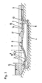
- the water sports device shown in FIGS. 1 to 3 in each case in longitudinal section has a water tank 1 as shown in DE-C-17 03 746 mentioned at the beginning.
- the water tank 1 which has an obliquely upwardly extending, in particular concavely curved bottom surface 2, adjoins a high tank 5 with a lower outlet extending over the entire width.
- the outlet of the elevated tank 1 forms the inflow nozzle 3, which is arranged at the lower edge of the bottom surface 2.
- the upper edge 8 of the bottom surface 2 forms an overflow 9 into an additional basin 7, the capacity of which corresponds at least to the filling volume of the tall container 5, but is preferably substantially larger.
- the end of the first area 10 is formed by a vertically arranged grille 14, on the downstream side of which a backflow flap 15 is arranged.
- the grid 14 divides the first area 10 from an area 11 further away from the overflow 9, in which the inlet 13 is arranged to a return line 4, which in this exemplary embodiment is formed by a closed pipeline running below the water tank 1, which runs from below into the outlet area of the tall container 5 opens.
- a circulation pump 6 is inserted into the return line 4. In the rest position shown in FIG.
- the backflow flap 15 receives the water in the area 11 at a higher level than in the area 10, from which it could partially flow back via the overflow 9 when the water tank 1 is emptied by pumping devices (not shown).
- the water tank 1 is delimited by walls 16 ′, which end approximately at the seat height above the water level of the shooting flow, in order to enable easy entry and exit into the water tank 1.
- An outer pair of side walls 16 ′′ delimits the water tank 1 and the additional pool 7 at a height above the level of the start shaft 17, the side walls 16 ′ being at least at the lowest point from the one above the floor surface 2 when the device is at a standstill before the high tank 5 is filled
- the additional pool 7 is of course provided with a transverse wall at the end, since the area 11 of the additional pool 7 and the elevated tank 5 communicate via the return line 4, the water level in the elevated tank 5 corresponds to that in the area 11 of the additional pool 7, ie the elevated tank 5 is only partially filled.
- the circulation pump 6 is initially activated, which comes from the area 11 of the additional pool 7 Sucks off water and fills the elevated tank 5, as shown in Fig.2. Initially, the inlet nozzle 3 remains closed until the required water level in the elevated tank 5 is reached.
- the area 11 of the additional basin still contains a sufficient water supply, from which water can be withdrawn at least as long as there is no large lowering of the mirror, until the water that shoots up over the bottom surface 2 re-enters the area 11 of the additional basin 7 from the inflow nozzle 3 that is now to be opened, so that the water cycle continues continuously.
- 3 shows the situation in which the start wave 17 formed by the flow start has reached the first area 10 of the additional basin 7, in which water is therefore still drawn from the area 11 without replenishment, the elevated tank 5 again partially emptied.
- the starting wave 17, which widens in the direction of flow, will subsequently reach the grating 14 and open the backflow flap 15, so that the water enters area 11, with which the water cycle can begin.
- the water tank 1 can be used to practice the sliding sports.
- the glider enters via one of the lower side walls 16 'on which he initially sits and can leave the water, container 1 again via the opposite lower side wall 16 ". If the athlete falls or his skill is still too low, he will over the Overflow 9 rinsed into the first area 10 of the additional basin 7, in which a noticeable there is a reduced flow velocity at a shallower water depth. He can therefore get out of the water sports device laterally in this area without disturbing the shooting flow in the water tank 1 and recover his sports equipment, which is caught on the grille 14. A practiced or lying surfer can also go out over the overflow 9 and get out in the same way.
- FIG. 1 A top view of a preferred embodiment is shown in FIG.
- the water tank 1 is here part of a leisure facility with a swimming channel 31, a children's pool 32, a non-swimmer pool 33 and a swirl pool 34.
- the elevated tank 5 is arranged on the left side of the water tank 1 in the drawing, whose outlet forms the inflow nozzle 3 to the rising bottom surface 2.
- the overflow 9 at the upper edge 8 of the rising floor surface 2 leads into the additional pool 7, which is divided by the grille 14 into the first area 10 adjoining the overflow 9, which is provided for the athletes' exit, and into the further area 11, from which the return line 4 starts.
- This is designed as an open channel and extends in any line around the water tank 1 again to the elevated tank 5 on the side opposite the feed line 3.
- the water circulation between the additional basin 7 and the inflow nozzle 3 necessary for the operation of the water sports device is utilized in various ways by the open channel. Cross-sectional changes in the swimming channel 31 thus result in different flow velocities, so that it is also possible to successfully swim against the current with, across and in places.
- the non-swimmer pool 33 and the start of the swimming channel 31 there is a partition 37 which can be flooded by the starting shaft 17, so that the starting shaft 17 is broken down and the starting process in the return channel is thus delayed.
- the adjoining walls of the swimming channel 31 can be kept lower.
- the swimming channel 31 can also be very long because it absorbs less water during the starting process.
- the water in the children's pool 32 is driven by an exchange of impulses from the swimming channel, with a separation 39 which prevents the exchange of energy as little as possible.
- the non-swimmer pool 33 is separated from the swirl pool 34 by a rope 40 carried by a float.
- the end section of the open channel is covered by an accessible cover 38 and separated from the vortex pool 34 by a slider 41.
- the circulating pump 6 is arranged in the transition between the end section of the return flow line and the elevated tank 5, the operation of the water sports device running as described above.
- the grid 14 in the additional basin 7 is again associated with the mentioned backflow flap 15, which prevents the backflow of water from the open channel into the emptied water tank 1. If the channel is long and resistant, the water level 19 can lie below the floor in the overflow 9 when the device is at rest (dash-dotted lines in FIG. 5), so that the arrangement of a backflow flap 15 can also be dispensed with.
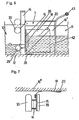
- the grille 14 with the backflow flap 15 is shown in detail in FIGS. 6 and 7, the situation corresponding to FIG. 2 being shown in the two areas 10, 11.
- the grid 14 consists of a number of vertical flat bars, on which a floating body 30 is loosely suspended, pointing towards the floor 11, which serves to protect the washed-up sports equipment.
- a hose 29 or the like is provided in the area of the grille 14 near the bottom.
- the cross-sectional shape as shown in dashed lines, can be changed by a pressure medium.
- the resistance of the grating 14 during operation of the device can be varied continuously, as a result of which the position of the transition stage from shooting into normal flow in the first region 10 of the additional basin 7 can also be changed.
- the backflow flap 15 is movably connected to the bottom and a seal 18 to the side wall 16 by means of a waterproof hinge 28, both the hinge 28 and the seal 18 each consisting of flexible film.
- the side seal 18 is fixed by means of a bar 20 "attached obliquely to the side wall 16", so that the backflow flap 15 folds down into the dash-dot position when the flow starts, and is pushed up again by a buoyancy body 39 when the water container 1 is emptied Access barrier referred to, which consists for example of individual vertical bars to which a cross bar 43 is attached as a handle.
- Backflow flaps 26 are connected to the grid 24 of the first additional basin 7 and are opened when the flow starts and are closed again by the water pumped back into the second elevated tank 25 when the second water tank 21 is emptied.
- the circulation pump 6 is arranged at the foot of the first elevated tank 5, and a connecting line 27 provided by a flap 44 is formed between the two elevated tanks 5, 25.
- both high tanks 5 and 25 are filled to the same height with water. Then the flap 44 is closed and the inflow nozzles 3 and 23 are opened in such a chronological order that when the start wave arrives from the water tank 1 the level in the elevated tank 25 is just below that of the start wave, as a result of which the backflow flaps 26 open.
- the water sports device allows the problem-free installation of gearless submersible pumps 6, which are preferably produced in series, and the simultaneous practice of various water sports by numerous people.
Landscapes
- Farming Of Fish And Shellfish (AREA)
- Special Spraying Apparatus (AREA)
- Structures Of Non-Positive Displacement Pumps (AREA)
- Massaging Devices (AREA)
Abstract
Description
Die Erfindung betrifft eine Wassersporteinrichtung mit einem Wasserbehälter mit einer ansteigenden Bodenfläche, mit einer sperrbaren Zuflußdüse entlang des unteren Randes der Bodenfläche, aus der das Wasser über die ansteigende Bodenfläche in schießender Strömung aufwärts geleitet wird, mit einer Rückflußleitung, die das über den oberen Rand der Bodenfläche strömende Wasser wieder zurück zur Zuflußdüse führt, und deren Eingang durch ein Gitter abgedeckt ist, mit einem oberhalb der Zuflußdüse angeordneten Hochbehälter zur Aufnahme der für den Startvorgang erforderlichen Wassermenge, und mit einer Umwalzpumpe in der Rückflußleitung.The invention relates to a water sports device with a water tank with a rising bottom surface, with a lockable inflow nozzle along the lower edge of the bottom surface, from which the water is directed upwards in a flowing flow over the rising bottom surface, with a return line, which over the upper edge of the Water flowing from the bottom surface leads back to the inflow nozzle, and the entrance of which is covered by a grille, with an elevated tank arranged above the inflow nozzle for receiving the amount of water required for the starting process, and with a circulating pump in the return flow line.
In der DE-C-17 03 746 (Fig.5) ist eine Wassersporteinrichtung beschrieben, die insbesondere zur Ausübung von Gleitsportarten, wie Wellenreiten, Wasserschilauf usw. geeignet ist.DE-C-17 03 746 (Fig. 5) describes a water sports device which is particularly suitable for practicing gliding sports, such as surfing, water skiing, etc.
In dieser Wassersporteinrichtung wird das Wasser über den ansteigenden Boden des Wasserbehälters mit einer Strömungsgeschwindigkeit aufwärts geleitet, die größer als die Grundwellengeschwindigkeit ist, wobei durch die schräg nach unten gerichtete, durch Schwerpunktverlagerung veränderbare Gewichtskomponente des Sportlers auf dem Gleitsportgerät der entgegengesetzt gerichtete Strömungswiderstand zumindest teilweise kompensiert wird. Es ist daher auch die freihändige, länger andauernde Ausübung der Sportarten möglich. Bevorzugt wird das Wasser dabei im Kreislauf von einer unteren Zuflußdüse aus über die ansteigende Bodenfläche nach oben in schießender Strömung nach oben und über eine unter dem Behälter angeordnete Rückflußleitung zur Zuflußdüse zurückgeführt. Ein wesentliches Merkmal ist dabei, daß die beim Austreten aus der Zuflußdüse hohe kinetische Energie des Wassers während des Hochschießens großteils in potentielle Energie umgewandelt wird, die dank der Rückflußleitung wiederverwertet werden kann. Zur Förderung des Wassers im Kreislauf ist daher nur eine geringe Energiezufuhr zur Umwälzpumpe nötig, da diese nur die Strömungsverluste decken muß.In this water sports device, the water is directed upwards over the rising bottom of the water tank at a flow speed that is greater than the fundamental wave speed, whereby the opposing flow resistance is at least partially compensated for by the athlete's weight component on the gliding device, which can be changed by shifting the center of gravity . Therefore, hands-free, longer-lasting practice of the sports is also possible. The water is preferably recirculated from a lower inflow nozzle via the rising bottom surface upwards in a flowing flow and back to the inflow nozzle via a reflux line arranged under the container. An important feature is that the high kinetic energy of the water when it emerges from the inflow nozzle is largely converted into potential energy during the shooting up, which energy can be reused thanks to the return line. To pump the water in the circuit, only a small amount of energy is required to the circulating pump, since this only has to cover the flow losses.
Es ergeben sich jedoch mitunter Schwierigkeiten beim Startvorgang, da, soll der Zusammenbruch des Wasserkreislaufes vermieden werden, die in die Rückflußleitung eingesetzte Umwälzpumpe erst dann mit der Rückförderung des Wassers beginnen darf, wenn dem Eingang der Rückflußleitung eine im ausreichenden Ausmaß über den oberen Rand der Bodenfläche überlaufende Wassermenge zufließt. Andererseits erfordert aber die Beschleunigung des in der Rückflußleitung vorhandenen Wassers durch die Umwälzpumpe bis zur Erreichung der erforderlichen Strömungsgeschwindigkeit eine gewisse Zeit, die nicht zur Verfügung steht, da die hochlaufende Strömung früher zusammenbricht.However, there are sometimes difficulties in the starting process, because if the breakdown of the water circuit is to be avoided, the circulating pump used in the return line may only begin to return the water when the entrance to the return line is sufficiently above the upper edge of the floor area overflowing amount of water flows. On the other hand, however, the acceleration of the water present in the reflux line by the circulating pump until the required flow rate is reached requires a certain amount of time, which is not available, since the upstream flow breaks down earlier.
Eine weitere dieses Prinzip enthaltende Wassersporteinrichtung beschreibt die EP-A-96 216. Hierbei wird bei unveränderter Energiezufuhr eine Vergrößerung des Neigungswinkels der ansteigenden Bodenfläche erzielt, indem vor allem an der Bodenfläche infolge Reibung abgebremste Wassermengen, die einen vorzeitigen Zusammenbruch der Strömung bewirken würden, abgesaugt und/oder durch Zuführung von Wasser mit erhöhter Strömungsgeschwindigkeit beschleunigt werden. Bei einer Ausführung dieser Einrichtung (Fig.8) ist ein Hochbehälter, der die zum Start benötigte Wassermenge aufnimmt, an der Seite des oberen Randes der Bodenfläche angeordnet, wobei das Wasser beim Startvorgang aus dem Hochbehälter über die Rückflußleitung zur Zuflußdüse gelangt. Hier wird die Umwälzpumpe vor der Öffnung der Zuflußdüse in Tätigkeit gesetzt, sodaß die Schwierigkeiten beim Startvorgang verringert sind, doch sind auch hier verschiedene Nachteile gegeben, die einen attraktiven Einsatz in der Praxis erschweren.Another water sports device containing this principle is described in EP-A-96 216. Here, with unchanged energy supply, an increase in the angle of inclination of the rising floor area is achieved by suctioning off, especially on the floor area, water which has been braked due to friction and which would cause the flow to collapse prematurely and / or accelerated by supplying water at an increased flow rate. In one embodiment of this device (FIG. 8), an elevated tank, which holds the amount of water required for starting, is arranged on the side of the upper edge of the bottom surface, the water reaching the inflow nozzle from the overhead tank via the return line during the starting process. Here the circulation pump is activated before the opening of the inlet nozzle, so that the difficulties during the starting process are reduced, but here too there are various disadvantages which make it difficult to use in practice.
Bei beiden bekannten Wassersporteinrichtungen erstreckt sich entlang des oberen Randes der ansteigenden Bodenfläche das den Eingang der Rückflußleitung überdeckende Gitter, das aus Sicherheitsgründen erforderlich ist. Durch dieses Gitter werden gestürzte Wassersportler und deren Sportgerät (Surfbretter, Wasser-ski etc.) davor bewahrt, in die Rückflußleitung eingesaugt zu werden. Es hat sich dabei aber gezeigt, daß der Ausstieg gestürzter Wassersportler im Bereich des Gitters und vor allem die Entnahme der Wassersportgeräte verhältnismäßig schwierig ist, so daß meist äußere Hilfe beansprucht werden muß. Weiters besteht die Gefahr, daß dabei der Wasserkreislauf so gestört wird, daß die schießende Strömung an der ansteigenden Bodenfläche zusammenbricht. Für einen neuen Start der Einrichtung ist aber nach der Schließung der Zuflußdüse die Rückführung des über der ansteigenden Bodenfläche stehenden Wassers in den Hochbehälter erforderlich.In both known water sports devices, the grille covering the entrance of the return line extends along the upper edge of the rising floor surface and is required for safety reasons. This grille prevents fallen water athletes and their sports equipment (surfboards, water skis etc.) from being sucked into the return line. It has been shown, however, that the exit of fallen water sports enthusiasts in the area of the grating and, above all, the removal of the water sports equipment is relatively difficult, so that external help usually has to be claimed. Furthermore, there is a risk that the water cycle will be disturbed so that the shooting current breaks down on the rising surface of the floor. For a new start of the facility, however, it is necessary to return the water above the rising floor area to the elevated tank after the inlet nozzle has been closed.
Ein weiterer Nachteil derartiger Wassersporteinrichtungen besteht darin, daß sie ausschließlich für die beschriebenen Sportarten geeignet sind, und daher unabhängig von bestehenden oder neu zu bauenden Schwimmbecken, etwa in Freizeitanlagen zu erstellen sind.Another disadvantage of such water sports facilities is that they are only suitable for the sports described and are therefore to be created independently of existing or new swimming pools, for example in leisure facilities.
Die Erfindung hat es sich nun zur Aufgabe gestellt, eine Wassersporteinrichtung der eingangs genannten Art so weiterzubilden, daß nicht nur störungsfreier Start und Betrieb, sondern bevorzugt auch das Aussteigen der Wassersportler, insbesondere nach einem Sturz, und die Entfernung der Sportgeräte ohne Schwierigkeiten möglich sind. Des weiteren soll eine Möglichkeit gefunden werden, die Wassersporteinrichtung als integrierten Bestandteil eines Großbeckens in einer Freizeitanlage auszubilden.The invention has now set itself the task of developing a water sports device of the type mentioned so that not only trouble-free start and operation, but preferably also getting out of the water sports enthusiasts, especially after a fall, and the removal of sports equipment are possible without difficulty. Furthermore, a possibility is to be found to use the water sports facility as an integrated part of a large pool To train leisure facilities.
Erfindungsgemäß wird dies nun dadurch gelöst, daß an der dem Hochbehälter gegenüberliegenden Seite des Wasserbehälters an diesen ein Zusatzbecken angeschlossen ist, dessen Fassungsvermögen zumindest dem Füllvolumen des Hochbehälters entspricht, wobei der obere Rand der ansteigenden Bodenfläche einen Überlauf in das Zusatzbecken bildet, von dem die Rückflußleitung ausgeht.According to the invention, this is now achieved in that an additional basin is connected to the side of the water basin opposite the elevated basin, the capacity of which corresponds at least to the filling volume of the elevated basin, the upper edge of the rising floor area forming an overflow into the additional basin, from which the return line going out.
Die Ausbildung eines Zusatzbeckens an der dem Hochbehälter gegenüberliegenden Seite der ansteigenden Bodenfläche schafft nun an dieser Seite der Wassersporteinrichtung einen ausreichenden Wasservorrat, um die Umwälzpumpe in der Rückflußleitung bereits vor oder spätestens unmittelbar bei der Öffnung der Zuflußdüse einzuschalten, da aus diesem Wasservorrat Wasser rückgeleitet werden kann, bis das aus dem Hochbehälter und der Zuflußdüse austretende Wasser den Überlauf erreicht hat, so daß die kontinuierliche Wasserzirkulation ungestört erreicht wird. Eine gesonderte Sperre an der Mündung der Rückflußleitung in den Hochbehälter kann sich dabei dann erübrigen, wenn für den Strömungsstart ein Teil des Wasservorrates zuerst in den Hochbehälter gepumpt und erst bei Erreichen eines bestimmten Wasserstandes die Zuflußdüse geöffnet wird. Da, um diesen Zweck zu erreichen, ein bestimmtes Wasservolumen im Zusatzbecken nicht unterschritten werden darf, jedoch eine obere Begrenzung nicht unmittelbar existiert, kann das Zusatzbecken in beliebiger Größe und Form ausgebildet werden. Dies ermöglicht es nun, einen einfachen und problemlosen Ausstieg aus der Wassersporteinrichtung außerhalb der ansteigenden Bodenfläche dadurch zu schaffen, daß der Überlauf durch eine Bodenschwelle gebildet ist, und in einem ersten anschließenden Bereich des Zusatzbeckens eine geringe Wassertiefe und eine anfangs geringfügig von der Bodenschwelle weg geneigte Bodenfläche vorgesehen ist, wobei der Eingang der Rückflußleitung in einem weiter entfernten Bereich des Zusatzbeckens angeordnet ist, in dem vorzugsweise die Wassertiefe größer ist.The formation of an additional basin on the side of the rising floor surface opposite the elevated tank now creates a sufficient water supply on this side of the water sports device in order to switch on the circulation pump in the reflux line before or at the latest when the inflow nozzle is opened, since water can be returned from this water supply until the water emerging from the elevated tank and the inflow nozzle has reached the overflow, so that the continuous water circulation is achieved undisturbed. A separate lock at the mouth of the reflux line into the elevated tank can be dispensed with if part of the water supply is first pumped into the elevated tank for the start of the flow and the inflow nozzle is only opened when a certain water level is reached. Since, in order to achieve this purpose, a certain water volume in the additional basin must not be undercut, but an upper limit does not immediately exist, the additional basin can be designed in any size and shape. This now makes it possible to create a simple and problem-free exit from the water sports device outside the rising floor area in that the overflow is formed by a threshold and in a first subsequent region of the additional pool a shallow water depth and an inclination initially slightly away from the threshold Bottom surface is provided, the inlet of the return line being arranged in a more distant area of the additional basin, in which the water depth is preferably greater.
In diesem ersten seichten Bereich des Zusatzbeckens, in dem die Strömungsgeschwindigkeit des Wassers nicht mehr allzu größ ist, kann also die Wassersporteinrichtung verlassen werden, ohne daß die schießende Strömung entlang der ansteigenden Bodenfläche gestört wird, und ohne daß die Wassersportler und ihre Sportgeräte in den Sog der aus dem weiter entfernten Bereich ausgehenden Rückflußleitung geraten. Das Fanggitter ist dabei vorteilhaft als lotrechter Abschluß dieses ersten seichten Bereiches vorgesehen.In this first shallow area of the additional pool, in which the flow speed of the water is no longer too great, the water sports facility can be left without disturbing the shooting current along the rising floor area and without the water sports enthusiasts and their sports equipment being sucked into the water the return line coming from the further away area. The grille is advantageously provided as the vertical termination of this first shallow area.
Beim Strömungsstart der Wassersporteinrichtung bildet sich im ersten Bereich des Zusatzbeckens eine Startwelle, die den Wasserstand im Zusatzbecken erhöht. Im zweiten Bereich, in dem bevorzugt durch Bodenabsenkung eine zum Schwimmen geeignete Wassertiefe gegeben ist, kann diese Wassertiefe auch nach Stillsetzung der Umwälzpumpe und Entleerung des über der ansteigenden Bodenfläche verbleibenden Wassers gehalten werden, wenn stromabwärts des Gitters eine Rückstauklappe angeordnet ist. Diese Rückstauklappe kann nun um eine horizontale Achse schwenkbar angeordnet sein, sodaß sie durch die beim Strömungsstart ankommende Wasserfront geöffnet, durch die nachfolgende Überströmung offengehalten, und bei Absperrung der Zuflußdüse und Stillsetzung der Umwälzpumpe wieder geschlossen wird, wodurch der höhere Wasserstand in dem vom Überlauf weiter entfernten Bereich des Zusatzbeckens erhalten bleibt. Das Wasser kann dann über der ansteigenden Bodenfläche abgepumpt werden, um den neuerlichen Strömungsstart zu ermöglichen.When the flow of the water sports device starts, a start wave forms in the first area of the additional pool, which increases the water level in the additional pool. In the second area, in which a water depth suitable for swimming is preferably provided by lowering the floor, this water depth can also be maintained after the circulation pump has been stopped and the water remaining above the rising floor area has been emptied, if a backflow flap is arranged downstream of the grille. This backflow flap can now be arranged pivotable about a horizontal axis, so that it is opened by the water front arriving at the start of the flow, kept open by the subsequent overflow, and is closed again when the inlet nozzle is shut off and the circulation pump is shut off, which further increases the water level in the overflow distant area of the additional pool is preserved. The water can then be pumped out over the rising surface of the floor to allow the flow to start again.
Da das Zusatzbecken keine obere Begrenzung seines Fassungsvermögens aufweist, kann daraus eine weitere vorteilhafte Ausbildung der Wassersporteinrichtung abgeleitet werden. Es wird so nämlich möglich, einen großen Teil der Rückflußleitung als offenes Gerinne auszubilden, das sich in beliebiger Formgebung um den Wasserbehälter mit der ansteigenden Bodenfläche herum erstreckt, und sein anderes Ende somit unmittelbar beim Hochbehälter aufweist, in den es an der der Zuflußdüse gegenüberliegenden Seite mündet. Es verbleibt somit in diesem Mündungsbereich ein so kurz als möglich gehaltener geschlossener Abschnitt der Rückflußleitung, in den die Umwälzpumpe eingesetzt ist. In dem offenen Gerinne können durch Querschnittsänderungen, und geeignete Linienführungen verschiedene, den Anreiz der gesamten Anlage erhöhende Effekte erzielt werden. So kann z. B. die Strömungsgeschwindigkeit durch Querschnittsänderungen erhöht werden (aus der DE-A-22 22 594 bekannt), Wirbelbecken für Kinder und Erwachsene und Nichtschwimmerbecken vorgesehen werden, usw., sodaß die erfindungsgemäße Wassersporteinrichtung einen integrierten Bestandteil eines Großbeckens bildet. Dabei ist auch die Serienschaltung von zumindest zwei Wasserbehältern mit ansteigender Bodenfläche möglich, wobei der den Eingang der Rückflußleitung aufweisende Bereich des Zusatzbeckens den zweiten Hochbehälter darstellt.Since the additional pool has no upper limit of its capacity, a further advantageous design of the water sports device can be derived from this. It is thus possible to design a large part of the return line as an open channel, which extends in any shape around the water tank with the rising floor area, and thus has its other end directly at the elevated tank, into which it is on the side opposite the inflow nozzle flows. A closed section of the return line, in which the circulating pump is inserted, is thus kept as short as possible in this mouth region. In the open channel, cross-sectional changes and suitable lines can be used to achieve various effects that increase the appeal of the entire system. So z. B. the flow rate can be increased by changes in cross-section (known from DE-A-22 22 594), whirlpools for children and adults and non-swimmer pools are provided, etc., so that the water sports device according to the invention forms an integrated part of a large pool. In this case, it is also possible to connect at least two water tanks with an increasing floor area in series, the area of the additional tank having the inlet of the return line representing the second elevated tank.
Ist das offene Gerinne in einer längeren Linienführung ausgebildet oder soll ein Abschnitt erhöhter Strömungsgeschwindigkeit eingebaut werden, so ist, um die Seitenwände in diesem Abschnitt niederhalten zu können, und eine Fokalisierung der Startwelle zu vermeiden, in einer bevorzugten Ausführung vorgesehen, daß das offene Gerinne mit einem parallel geschalteten Schwimmkanal versehen ist, der durch eine Längstrennwand abgeteilt ist, wobei deren erster Abschnitt eine von der Startwelle überflutbare Höhe aufweist. Der durch die Startwelle hervorgerufene Wasserüberschuß strömt in diesem Fall über diese Längstrennwand, die den Schwimmkanal vorzugsweise vom Nichtschwimmerbecken abtrennt, auf kürzerem Wege zum Hochbehälter.If the open channel is designed in a longer line or if a section of increased flow speed is to be installed, in order to be able to hold down the side walls in this section and to avoid focalization of the start wave, it is provided in a preferred embodiment that the open channel be a parallel swimming channel is provided, which is divided by a longitudinal partition, wherein whose first section has a height that can be submerged by the starting wave. The excess water caused by the start wave flows in this case via this longitudinal partition wall, which preferably separates the swimming channel from the non-swimmer pool, in a shorter way to the elevated tank.
Nachstehend wird nun die Erfindung an Hand der Figuren der beiliegenden Zeichnungen näher beschrieben, ohne darauf beschränkt zu sein.The invention will now be described in more detail below with reference to the figures in the accompanying drawings, without being limited thereto.
Es zeigen:
- Fig.1 bis 3 eine erste schematische Ausführung der Wassersporteinrichtung im Längsschnitt, wobei Fig.1 die Einrichtung in Ruhestellung, Fig.2 nach dem Einschalten der Umwälzpumpe, und Fig.3 beim Strömungsstart zeigt,
- Fig.4 eine Draufsicht auf eine bevorzugte Ausführung einer Wassersporteinrichtung als Teil einer Freizeitanlage,
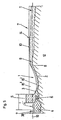
- Fig.5 einen Längsschnitt nach der Linie V-V der Fig.4,
- Fig.6 im Detail die Ausbildung des Gitters und der Rückstaubklappe im Vertikalschnitt,
- Fig.7 Gitter und Rückstauklappe im Horizontalschnitt, und
- Fig.8 eine schematische Darstellung zweier in Serie angeordneter Wassersporteinrichtungen als Teil einer Freizeitanlage ähnlich Fig.4.
- 1 to 3 a first schematic embodiment of the water sports device in longitudinal section, FIG. 1 showing the device in the rest position, FIG. 2 after the circulation pump has been switched on, and FIG. 3 when the flow starts,
- 4 shows a plan view of a preferred embodiment of a water sports facility as part of a leisure facility,
- 5 shows a longitudinal section along the line VV of Figure 4,
- 6 shows in detail the design of the grille and the backflow flap in vertical section,
- Fig.7 grille and backflow flap in horizontal section, and
- 8 shows a schematic representation of two water sports facilities arranged in series as part of a leisure facility similar to FIG. 4.
Die in den Fig.1 bis 3 jeweils im Längsschnitt gezeigte Wassersporteinrichtung weist einen Wasserbehälter 1 auf, wie er in der eingangs erwähnten DE-C-17 03 746 gezeigt ist. An einen Hochbehälter 5 mit einem unteren, über die gesamte Breite reichenden Auslaß schließt der Wasserbehälter 1 an, der eine schräg aufwärts verlaufende, insbesondere konkav gewölbte Bodenfläche 2 aufweist. Der Auslaß des Hochbehälters 1 bildet die Zuflußdüse 3, die am unteren Rand der Bodenfläche 2 angeordnet ist. Der obere Rand 8 der Bodenfläche 2 bildet einen Überlauf 9 in ein Zusatzbecken 7, dessen Fassungsvermögen zumindest dem Füllvolumen des Hochbehälters 5 entspricht, vorzugsweise jedoch wesentlich größer ist. In einem ersten Bereich 10 des Zusatzbeckens 7, der unmittelbar an den Überlauf 9 anschließt, ist die Tiefe des Zusatzbeckens 7 sehr gering, wobei die Bodenfläche 12 anfangs geringfügig abfällt und anschließend horizontal verläuft. Den Abschluß des ersten Bereiches 10 bildet ein vertikal angeordnetes Gitter 14, an dessen stromabwärts gelegener Seite eine Rückstauklappe 15 angeordnet ist. Das Gitter 14 teilt den ersten Bereich 10 von einem vom Überlauf 9 weiter entfernten Bereich 11, in dem der Eingang 13 zu einer Rückflußleitung 4 angeordnet ist, die in diesem Ausführungsbeispiel durch eine geschlossene unterhalb des Wasserbehälters 1 verlaufende Rohrleitung gebildet ist, die von unten in den Auslaßbereich des Hochbehälters 5 mündet. In die Rückflußleitung 4 ist eine Umwälzpumpe 6 eingesetzt. Die Rückstauklappe 15 erhält dabei in der in Fig.1 gezeigten Ruhestellung das Wasser im Bereich 11 auf einem höheren Niveau als im Bereich 10, aus dem es ja bei Entleerung des Wasserbehälters 1 durch nicht gezeigte Pumpeinrichtungen über den Überlauf 9 teilweise zurückfließen könnte. An den Längsseiten ist der Wasserbehälter 1 durch Wände 16' begrenzt, die etwa in Sitzhöhe über dem Wasserspiegel der schießenden Strömung enden, um einen bequemen Ein- und Ausstieg in den Wasserbehälter 1 zu ermöglichen. Ein äußeres Seitenwandpaar 16" begrenzt den Wasserbehälter 1 und das Zusatzbecken 7 in einer Höhe über dem Niveau der Startwelle 17, wobei bei Stillstand der Einrichtung vor der Füllung des Hochbehälters 5 die Seitenwände 16' zumindest an der tiefsten Stelle von dem über der Bodenfläche 2 stehenden Wasser überflutet sind. Das Zusatzbecken 7 ist am Ende selbstverständlich mit einer Querwand versehen. Da der Bereich 11 des Zusatzbeckens 7 und der Hochbehälter 5 über die Rückflußleitung 4 kommunizieren, entspricht der Wasserstand im Hochbehälter 5 jenem im Bereich 11 des Zusatzbeckens 7, d.h. der Hochbehälter 5 ist nur zu einem kleinen Teil gefüllt.The water sports device shown in FIGS. 1 to 3 in each case in longitudinal section has a
Um nun die Wassersporteinrichtung zu starten, die im Wasserbehälter 1 zur Ausübung von Gleitsportarten, wie Wellenreiten, Wasserschilauf usw. eine über die ansteigende Bodenfläche 2 aufwärts schießende Strömung benötigt, wird vorerst die Umwälzpumpe 6 in Tätigkeit gesetzt, die aus dem Bereich 11 des Zusatzbeckens 7 Wasser absaugt und den Hochbehälter 5 füllt, wie dies in Fig.2 gezeigt ist. Dabei bleibt anfangs die Zuflußdüse 3 noch verschlossen, bis der erforderliche Wasserstand im Hochbehälter 5 erreicht ist. Dabei enthält der Bereich 11 des Zusatzbeckens noch einen ausreichenden Wasservorrat, dem zumindest solange noch Wasser ohne große Spiegelabsenkung entnommen werden kann, bis aus der nunmehr zu öffnenden Zuflußdüse 3 das über die Bodenfläche 2 hochschießende Wasser wieder in den Bereich 11 des Zusatzbeckens 7 eintritt, sodaß der Wasserkreislauf kontinuierlich fortgesetzt wird. In Fig. 3 ist jene Situation gezeigt, in der die durch den Strömungsstart sich bildende Startwelle 17 den ersten Bereich 10 des Zusatzbecken 7 errsicht hat, in der also noch Wasser aus dem Bereich 11 ohne Nachschub abgezogen wird, wobei sich der Hochbehälter 5 wieder teilweise entleert. Die sich in Strömungsrichtung verbreiternde Startwelle 17 wird in weiterer Folge das Gitter 14 erreichen und die Rückstauklappe 15 öffnen, so daß das Wasser in den Bereich 11 eintritt, womit der Wasserkreislauf beginnen kann. Sobald dies erfolgt ist, kann der Wasserbehälter 1 zur Ausübung der Gleitsportarten benützt werden. Der Gleitsportler steigt über eine der niederen Seitenwände 16' ein, auf der er anfänglich sitzt und kann den Wasser, Behälter 1 wieder über die gegenüberliegende niedere Seitenwand 16" verlassen. Stürzt der Sportler oder ist sein Können noch zu gering, so wird er über den Überlauf 9 in den ersten Bereich 10 des Zusatzbeckens 7 gespült, in dem eine merklich verringerte Strömungsgeschwindigkeit bei geringerer Wassertiefe gegeben ist. Er kann daher in diesem Bereich ohne Probleme, und ohne die schießende Strömung im Wasserbehälter 1 zu stören, aus der Wassersporteinrichtung seitlich aussteigen und sein Sportgerät bergen, das am Gitter 14 aufgefangen wird. Ein geübter oder liegender Surfer kann über den Überlauf 9 auch ausfahren, und in gleicher Weise aussteigen.In order to start the water sports device that requires a flow that shoots upwards over the rising
In Fig.4 ist eine Draufsicht auf eine bevorzugte Ausführung gezeigt. Der Wasserbehälter 1 ist hier Teil einer Freizeitanlage mit einem Schwimmkanal 31, einem Kinderbecken 32, einem Nichtschwimmerbecken 33 und einem Wirbelbecken 34. Wie vor allem aus Fig.5 ersichtlich, ist an der in der Zeichnung linken Seite des Wasserbehälters 1 der Hochbehälter 5 angeordnet, dessen Auslauf die Zuflußdüse 3 zur ansteigenden Bodenfläche 2 bildet. Der Überlauf 9 am oberen Rand 8 der ansteigenden Bodenfläche 2 führt in das Zusatzbecken 7, das durch das Gitter 14 in den ersten an den Überlauf 9 anschließenden Bereich 10, der zum Ausstieg der Sportler vorgesehen ist, und in den weiteren Bereich 11 unterteilt ist, von dem die Rückflußleitung 4 ausgeht. Diese ist dabei als offenes Gerinne ausgebildet, und erstreckt sich in beliebiger Linienführung um den Wasserbehälter 1 herum wieder zum Hochbehälter 5 an derder Zuführleitung 3 gegenüberliegenden Seite. Die zum Betrieb der Wassersporteinrichtung notwendige Wasserumwälzung zwischen dem Zusatzbecken 7 und der Zuflußdüse 3 wird durch das offene Gerinne in verschiedener Weise ausgenützt. So entstehen durch Querschnittsänderungen im Schwimmkanal 31 unterschiedliche Strömungsgeschwindigkeiten, sodaß mit, quer und stellenweise auch erfolgreich gegen die Strömung geschwommen werden kann. Gleiches gilt für das Wirbelbecken 34, dessen Kern 36 flüssig oder fest sein kann, wobei am Eingang in das Wirbelbecken 34 eine Klappe 35 um eine vertikale Achse verstellbar ist, durch die die Wassergeschwindigkeit im Wirbelbecken 34 geregelt werden kann. Zwischen dem Nichtschwimmerbecken 33 und dem Beginn des Schwimmkanals 31 ist eine von der Startwelle 17 überflutbare Trennwand 37 angeordnet, so daß die Startwelle 17 abgebaut und damit der Startvorgang im Rücklaufkanal verzögert wird. Dies führt zu einer temporären Durchströmung des Nichtschwimmerbeckens 33 (strichlierte Pfeile), was Wasser auf kurzem Wege der Pumpe 6 zuführt. Dadurch können die anschließenden Wände des Schwimmkanals 31 niederer gehalten werden. Der Schwimmkanal 31 kann dadurch auch sehr lang sein, da er beim Startvorgang weniger Wasser aufnimmt. Das Wasser im Kinderbecken 32 wird durch Impulsaustausch vom Schwimmkanal aus angetrieben, wobei eine den Energieaustausch möglichst wenig hindernde Abtrennung 39 vorgesehen ist. Das Nichtschwimmerbecken 33 ist vom Wirbelbecken 34 durch ein schwimmkörpergetragenes Seil 40 abgetrennt. Der Endabschnitt des offenen Gerinnes ist durch eine begenhbare Überdeckung 38 abgedeckt und durch ein Gittel 41 vom Wirbelbecken 34 abgeteilt. Wie aus Fig.5 ersichtlich, ist im Übergang zwischen dem Endabschnitt der Rückflußletung und dem Hochbehälter 5 die Umwälzpumpe 6 angeordnet, wobei der Betrieb der Wassersporteinrichtung wie oben beschrieben abläuft.A top view of a preferred embodiment is shown in FIG. The
In Fig.4 ist dem Gitter 14 im Zusatzbecken 7 wieder die erwähnte Rückstauklappe 15 zugeordnet, die den Rückfluß des Wassers aus dem offenen Gerinne in den entleerten Wasserbehälter 1 verhindert. Ist das Gerinne lang und widerstandsreich, so kann der Wasserspiegel 19 bei ruhender Einrichtung (in Fig.5 strichpunktiert gezeichnet), unterhalb des Bodens im Überlauf 9 liegen, sodaß sich die Anordnung einer Rückstauklappe 15 auch erübrigen kann. Das Gitter 14 mit Rückstauklappe 15 ist im Detail in den Fig. 6 und 7 dargestellt, wobei hier in den beiden Bereichen 10, 11 etwa die Situation entsprechend Fig.2 gezeigt ist. Das Gitter 14 besteht aus einer Anzahl lotrechter flacher Stäbe, an denen zum Boden 11 weisend ein Schwimmkörper 30 lose aufgehängt ist, der zur Schonung der angespülten Sportgeräte dient. Im bodennahen Bereich des Gitters 14 ist ein Schlauch 29 od.dgl. angeordnet, dessen Querschnittsform, wie strichliert gezeigt, durch ein Druckmedium veränderbar ist. Dadurch läßt sich der Widerstand des Gitters 14 beim Betrieb der Einrichtung kontinuierlich variieren, wodurch sich auch die Lage der Übergangsstufe von schießender in normale Strömung im ersten Bereich 10 des Zusatzbeckens 7 verändern läßt.In Figure 4, the
Die Rückstauklappe 15 ist über ein wasserdichtes Scharnier 28 mit dem Boden und eine Dichtung 18 mit der Seitenwand 16 beweglich verbunden, wobei sowohl das Scharnier 28 als auch die Dichtung 18 jeweils aus biegsamer Folie bestehen. Die seitliche Dichtung 18 ist mittels einer schräg an der Seitenwand 16" befestigten Leiste 20 fixiert, sodaß die Rückstauklappe 15 beim Strömungsstart in die strichpunktierte Stellung nach unten klappt, und beim Entleeren des Wasserbehälters 1 durch einen Auftriebskörper 39 wieder hochgedrückt wird. Mit 42 ist eine Zugangssperre bezeichnet, die beispielsweise aus einzelnen vertikalen Stäben besteht, an denen eine als Haltegriff ausgebildete Querstange 43 befestigt ist.The
In der Ausführung nach Fig.8, bei der die Rückflußleitung 4 ebenfalls wieder durch ein offenes Gerinne in beliebiger Linienführung zum Hochbehälter 5 geführt ist, sind zwei für die Gleitsportausübung geeignete Wasserbehälter 1, 21 in Serie angeordnet. Dabei wird das erste Zusatzbecken 7 wiederum durch ein Gitter 14 in zwei Bereiche 10, 11 unterteilt. Im überlaufnahen Bereich 10 ist wiederum der Ausstieg möglich, und der überlaufferne Bereich 11 ist in dieser Ausführung durch einen zweiten Hochbehälter 25 gebildet, der an den zweiten Wasserbehälter 21 angeschlossen ist. Auch dieser weist eine ansteigende Bodenfläche 22 auf, über die das Wasser aus der Zuflußdüse 23 hochschießt und in das zweite Zusatzbecken 7 gelangt, das durch das Gitter 14 mit Rückstauklappe 15 wieder in den Ausstiegsbereich 10 und den vom Überlauf 9 entfernten Bereich 11 unterteilt ist, von dem das Gerinne seinen Anfang nimmt. Am Gitter 24 des ersten Zusatzbeckens 7 sind Rückstauklappen 26 angeschlossen, die bei Strömungsstart geöffnet und bei Entleerung des zweiten Wasserbehälters 21 durch das in den zweiten Hochbehälter 25 zurückgepumpte Wasser wieder verschlossen werden. Die Umwälzpumpe 6 ist am Fuße des ersten Hochbechälters 5 angeordnet, und zwischen den beiden Hochbehältern 5, 25 ist eine mittels einer Klappe 44 versehene Verbindungsleitung 27 ausgebildet.In the embodiment according to FIG. 8, in which the
Als Startvorbereitung werden bei geschlossenen Zuflußdüsen 3 und 23 und entleerten Wasserbehältern 1 und 21 beide Hochbehälter 5 und 25 gleich hoch mit Wasser gefüllt. Anschließend wird die Klappe 44 geschlossen und die Zuflußdüsen 3 und 23 werden in einer solchen zeitlichen Reihenfolge geöffnet, daß beim Ankommen der Startwelle aus dem Wasserbehälter 1 das Niveau im Hochbehälter 25 gerade knapp unter dem der Startwelle liegt, wodurch sich die Rückstauklappen 26 öffnen.As a preparation for the start, when the
Die erfindungsgemäße Wassersporteinrichtung erlaubt den problemlosen Einbau vorzugsweise serienmäßig erzeugter getriebeloser Tauchpumpen 6 und die gleichzeitige Ausübung verschiedener Wassersportarten durch zahlreiche Personen.The water sports device according to the invention allows the problem-free installation of gearless submersible pumps 6, which are preferably produced in series, and the simultaneous practice of various water sports by numerous people.
Claims (8)
Priority Applications (5)
| Application Number | Priority Date | Filing Date | Title |
|---|---|---|---|
| AT84114072T ATE29842T1 (en) | 1984-11-22 | 1984-11-22 | WATER SPORTS FACILITIES. |
| EP84114072A EP0182923B1 (en) | 1984-11-22 | 1984-11-22 | Appliance for practising aquatic sports |
| DE8484114072T DE3466353D1 (en) | 1984-11-22 | 1984-11-22 | Appliance for practising aquatic sports |
| US07/265,318 US4905987A (en) | 1984-11-22 | 1988-10-27 | Water sports apparatus |
| US07/843,950 USRE34407E (en) | 1984-11-22 | 1992-02-21 | Water sports apparatus |
Applications Claiming Priority (1)
| Application Number | Priority Date | Filing Date | Title |
|---|---|---|---|
| EP84114072A EP0182923B1 (en) | 1984-11-22 | 1984-11-22 | Appliance for practising aquatic sports |
Publications (2)
| Publication Number | Publication Date |
|---|---|
| EP0182923A1 EP0182923A1 (en) | 1986-06-04 |
| EP0182923B1 true EP0182923B1 (en) | 1987-09-23 |
Family
ID=8192296
Family Applications (1)
| Application Number | Title | Priority Date | Filing Date |
|---|---|---|---|
| EP84114072A Expired EP0182923B1 (en) | 1984-11-22 | 1984-11-22 | Appliance for practising aquatic sports |
Country Status (4)
| Country | Link |
|---|---|
| US (1) | US4905987A (en) |
| EP (1) | EP0182923B1 (en) |
| AT (1) | ATE29842T1 (en) |
| DE (1) | DE3466353D1 (en) |
Families Citing this family (67)
| Publication number | Priority date | Publication date | Assignee | Title |
|---|---|---|---|---|
| US5401117A (en) * | 1987-05-27 | 1995-03-28 | Lochtefeld; Thomas J. | Method and apparatus for containerless sheet flow water rides |
| US5271692A (en) * | 1987-05-27 | 1993-12-21 | Light Wave, Ltd. | Method and apparatus for a sheet flow water ride in a single container |
| US5171101A (en) * | 1987-05-27 | 1992-12-15 | Light Wave, Ltd. | Surfing-wave generators |
| US5236280A (en) * | 1987-05-27 | 1993-08-17 | Blade Loch, Inc. | Method and apparatus for improving sheet flow water rides |
| US5421782A (en) * | 1990-08-15 | 1995-06-06 | Light Wave, Inc. | Action river water attraction |
| US5667445A (en) * | 1988-12-19 | 1997-09-16 | Light Wave Ltd. | Jet river rapids water attraction |
| US5213547A (en) * | 1990-08-15 | 1993-05-25 | Light Wave, Ltd. | Method and apparatus for improved water rides by water injection and flume design |
| DE69114013T3 (en) | 1990-09-04 | 2002-04-18 | Light Wave, Ltd. | WAVE RIDING ATTRACTION. |
| FR2671977A1 (en) * | 1991-01-24 | 1992-07-31 | Int Indoor Productions | Installation for practising water gliding sports of the board sailing type |
| US5766082A (en) * | 1993-05-20 | 1998-06-16 | Lochtefeld; Thomas J. | Wave river water attraction |
| US5503597A (en) * | 1994-03-09 | 1996-04-02 | Lochtefeld; Thomas J. | Method and apparatus for injected water corridor attractions |
| US5637025A (en) * | 1995-12-12 | 1997-06-10 | Aquaplay Ab | Gate and harbor for water activity toy |
| US5899634A (en) * | 1996-10-22 | 1999-05-04 | Light Wave, Ltd. | Simulated wave water sculpture |
| US6161771A (en) * | 1997-05-23 | 2000-12-19 | Water Ride Concepts, Inc. | Water fountain system and method |
| US6758231B1 (en) | 1998-06-17 | 2004-07-06 | Light Wave Ltd. | Redundant array control system for water rides |
| US6261186B1 (en) * | 1998-07-24 | 2001-07-17 | Nbgs International, Inc. | Water amusement system and method |
| US6036603A (en) * | 1998-09-29 | 2000-03-14 | Universal Studios, Inc. | Whirlpool simulation effect |
| ATE312253T1 (en) | 1999-08-02 | 2005-12-15 | Light Wave Ltd | MOBILE WAVE RIDING ATTRACTION WITH A SLIDABLE COVER FOR A LOCK |
| US6454659B1 (en) | 2000-06-14 | 2002-09-24 | Forrest Noble | Kayaking simulation device for creating a recirculating hydraulic hole effect within a receiving pool |
| US6702687B1 (en) | 2000-06-23 | 2004-03-09 | Nbgs International, Inc. | Controller system for water amusement devices |
| WO2002022227A2 (en) * | 2000-09-11 | 2002-03-21 | Nbgs International, Inc. | Water amusement system and method |
| AU2689402A (en) | 2000-11-16 | 2002-05-27 | Thomas J Lochtefeld | Method and apparatus for a wave pools |
| US7179173B2 (en) * | 2002-03-25 | 2007-02-20 | Nbgs International Inc. | Control system for water amusement devices |
| US6920651B2 (en) * | 2003-06-05 | 2005-07-26 | Michael Kevin Roberts | Surfing ring wave pool for generating multiple simultaneous endless traveling waves looping around a center island |
| US7229359B2 (en) | 2003-10-24 | 2007-06-12 | Henry, Schooley & Associates, L.L.C. | Continuous water ride |
| US20050114706A1 (en) * | 2003-11-26 | 2005-05-26 | Destefano Jason Michael | System and method for the collection and transmission of log data over a wide area network |
| US7497784B2 (en) * | 2004-11-24 | 2009-03-03 | Water Ride Concepts, Inc. | Rollable carrier ride |
| US7597630B2 (en) * | 2004-11-24 | 2009-10-06 | Water Ride Concepts, Inc. | Water amusement park conveyors |
| US7921601B2 (en) * | 2005-04-20 | 2011-04-12 | Water Ride Concepts, Inc. | Water amusement system with trees |
| US7727077B2 (en) * | 2005-08-03 | 2010-06-01 | Water Ride Concepts, Inc. | Water amusement park water channel flow system |
| US7775895B2 (en) * | 2005-08-03 | 2010-08-17 | Water Ride Concepts, Inc. | Water amusement park water channel and adjustable flow controller |
| US7815514B2 (en) * | 2005-08-30 | 2010-10-19 | Water Ride Concepts, Inc. | Water amusement park conveyor barriers |
| US7371183B2 (en) * | 2005-08-30 | 2008-05-13 | Henry, Schooley & Associates, L.L.C. | Water amusement park conveyors |
| US7762899B2 (en) | 2005-08-30 | 2010-07-27 | Water Ride Concepts, Inc. | Water amusement park conveyor support elements |
| US20070049386A1 (en) * | 2005-08-30 | 2007-03-01 | Henry Jeffery W | Adjusting participant flow rate in water amusement parks |
| US8282497B2 (en) * | 2005-08-30 | 2012-10-09 | Water Ride Concepts, Inc. | Modular water amusement park conveyors |
| US8210954B2 (en) | 2005-09-02 | 2012-07-03 | Water Ride Concepts, Inc. | Amusement water rides involving exercise circuits |
| US7758435B2 (en) | 2005-09-02 | 2010-07-20 | Water Ride Concepts, Inc. | Amusement water rides involving interactive user environments |
| US20070054745A1 (en) * | 2005-09-02 | 2007-03-08 | Henry Jeffery W | Methods and systems for thermal control systems for self-contained floating marine parks |
| US7857704B2 (en) | 2005-09-15 | 2010-12-28 | Water Ride Concepts, Inc. | Amusement water rides involving games of chance |
| US7762900B2 (en) | 2006-03-14 | 2010-07-27 | Water Ride Concepts, Inc. | Method and system of positionable covers for water amusement parks |
| FR2906287B1 (en) * | 2006-09-26 | 2012-08-10 | Hydrostadium | INSTALLATION FOR THE PRACTICE OF AQUATIC ACTIVITIES |
| US9103133B2 (en) * | 2012-11-01 | 2015-08-11 | American Wave Machines, Inc. | Sequenced chamber wave generator controller and method |
| US20080286048A1 (en) * | 2007-03-09 | 2008-11-20 | Brandon Carnahan | Sheet flow water ride apparatus and method |
| US20080286047A1 (en) * | 2007-03-09 | 2008-11-20 | Brandon Carnahan | River water ride apparatus and method |
| WO2008112123A2 (en) * | 2007-03-09 | 2008-09-18 | Waveyard Development, Llc | Set wave system for wave generation |
| US20090169305A1 (en) * | 2007-11-13 | 2009-07-02 | Lochtefeld Thomas J | Method and apparatus for varying water flow for stationary sheet flow water rides |
| CN102307507B (en) * | 2008-11-25 | 2014-10-29 | 托马斯·J·勒希特费尔德 | Method and apparatus for dampening waves in a wave pool |
| US9550127B2 (en) | 2013-03-21 | 2017-01-24 | Thomas J. Lochtefeld | Padded grate drainage system for water rides |
| US9506259B2 (en) | 2008-11-25 | 2016-11-29 | Thomas J. Lochtefeld | Method and apparatus for dampening waves in a wave pool |
| US9856665B2 (en) | 2008-11-25 | 2018-01-02 | Thomas J. Lochtefeld | Method and apparatus for dampening waves in a wave pool |
| US9879438B2 (en) | 2008-11-25 | 2018-01-30 | Thomas J. Lochtefeld | Method and apparatus for dampening waves in a wave pool using padded grate drainage system |
| US8079916B2 (en) | 2008-12-18 | 2011-12-20 | Water Ride Concepts, Inc. | Themed amusement river ride system |
| CA3072158C (en) | 2013-10-30 | 2023-05-09 | Oriol A. Vicente | Inflatable surfing apparatus and method |
| US10458136B2 (en) | 2014-08-25 | 2019-10-29 | Thomas J. Lochtefeld | Method and apparatus for producing waves suitable for surfing using wave-forming caissons with floating wave attenuator |
| US9511297B2 (en) * | 2015-04-07 | 2016-12-06 | Universal City Studios Llc | Slide entry system |
| CA3221253A1 (en) | 2015-11-12 | 2017-05-12 | Whitewater West Industries Ltd. | Method and apparatus for fastening of inflatable ride surfaces |
| US10195535B2 (en) | 2015-11-12 | 2019-02-05 | Whitewater West Industries Ltd. | Transportable inflatable surfing apparatus and method |
| US10376799B2 (en) | 2015-11-13 | 2019-08-13 | Whitewater West Industries Ltd. | Inflatable surfing apparatus and method of providing reduced fluid turbulence |
| WO2017218902A1 (en) * | 2016-06-17 | 2017-12-21 | Davis Allen Tanner | System and method of generating wave |
| DE102017125738A1 (en) * | 2016-11-04 | 2018-05-09 | L + T Lengermann + Trieschmann GmbH + Co. KG | Wave plant for generating an artificial wave |
| CA3059049A1 (en) | 2016-11-08 | 2018-05-17 | 1090690 B.C. Ltd. | Wave producing method and apparatus |
| US10119285B2 (en) | 2017-01-20 | 2018-11-06 | The Wave Pool Company, LLC | Systems and methods for generating waves |
| US11273383B2 (en) | 2017-11-10 | 2022-03-15 | Whitewater West Industries Ltd. | Water ride attraction incorporating a standing wave |
| AT523412B1 (en) * | 2020-01-24 | 2021-08-15 | Gmeiner Tobias | Device and method for generating an artificial surf wave |
| US20240279947A1 (en) * | 2020-05-18 | 2024-08-22 | Whitewater West Industries Ltd. | Return channel for a surf pool |
| MX2022014589A (en) * | 2020-05-18 | 2023-05-15 | Whitewater West Ind Ltd | Pool wave generator. |
Family Cites Families (17)
| Publication number | Priority date | Publication date | Assignee | Title |
|---|---|---|---|---|
| DE159793C (en) * | ||||
| US490484A (en) * | 1893-01-24 | Steele mackaye | ||
| US1536875A (en) * | 1924-07-03 | 1925-05-05 | Edgar W Bowen | Swimming pool |
| GB375684A (en) * | 1930-12-02 | 1932-06-30 | Bamag Meguin Ag | Production of artificial waves in swimming pools and the like |
| US1884075A (en) * | 1931-06-15 | 1932-10-25 | Ericsson H Merritt | Consistency responsive device |
| FR761489A (en) * | 1933-09-19 | 1934-03-20 | Fairground attraction | |
| US2815951A (en) * | 1956-01-19 | 1957-12-10 | Nicholas T Baldanza | Water skiing training device |
| US3038760A (en) * | 1959-11-06 | 1962-06-12 | Donald W Crooke | Fish ladder |
| GB935054A (en) * | 1962-04-27 | 1963-08-28 | Flygts Pumpar Ab | Apparatus for studying of swimmers |
| GB1090262A (en) * | 1964-02-04 | 1967-11-08 | Frederick Hugh Percy Buckner | Improvements in and relating to apparatus for amusements and instructional purposes |
| GB1118083A (en) * | 1965-03-30 | 1968-06-26 | Gerald Douglas Marvin | Ski training and practising apparatus |
| GB1159269A (en) * | 1966-12-02 | 1969-07-23 | Richard Bobart Buswell | Apparatus for producing a Moving Fluid Surface |
| FR1539959A (en) * | 1967-08-11 | 1968-09-20 | Water sport apparatus | |
| US3473334A (en) * | 1968-06-24 | 1969-10-21 | Phillip Dexter | Apparatus and method for producing waves |
| DE2222594A1 (en) * | 1972-05-09 | 1973-11-29 | Karl Guenter Hoppe | SWIMMING POOL WITH CIRCULATING CURRENT |
| US3913332A (en) * | 1973-08-30 | 1975-10-21 | Arnold H Forsman | Continuous wave surfing facility |
| AT379513B (en) * | 1982-06-07 | 1986-01-27 | Frenzl Otto | WATER SPORTS EQUIPMENT |
-
1984
- 1984-11-22 EP EP84114072A patent/EP0182923B1/en not_active Expired
- 1984-11-22 DE DE8484114072T patent/DE3466353D1/en not_active Expired
- 1984-11-22 AT AT84114072T patent/ATE29842T1/en not_active IP Right Cessation
-
1988
- 1988-10-27 US US07/265,318 patent/US4905987A/en not_active Ceased
Also Published As
| Publication number | Publication date |
|---|---|
| DE3466353D1 (en) | 1987-10-29 |
| ATE29842T1 (en) | 1987-10-15 |
| US4905987A (en) | 1990-03-06 |
| EP0182923A1 (en) | 1986-06-04 |
Similar Documents
| Publication | Publication Date | Title |
|---|---|---|
| EP0182923B1 (en) | Appliance for practising aquatic sports | |
| EP0096216B1 (en) | Method for the practice of watersports in which water is directed upwardly over an inclined surface and watersport equipment for carrying out such a method | |
| DE69310719T2 (en) | METHOD AND DEVICE FOR A WATER SLIDE IN A SINGLE CONTAINER | |
| DE60027172T2 (en) | MOBILE WAVE RACE ATTRACTION WITH A SLIP-ON COVER FOR A SLAUGHTER | |
| DE19917507C2 (en) | Swimming pool with counter-current swimming system | |
| DE1808906A1 (en) | Device for generating waves for surfing | |
| DE1684877B2 (en) | Device for creating a movement of water in a swimming pool or other pool of water | |
| DE2222594A1 (en) | SWIMMING POOL WITH CIRCULATING CURRENT | |
| DE2130967C3 (en) | Device for separating two liquid components contained in a heterogeneous liquid | |
| DE102008057785A1 (en) | Artificial surfing facility | |
| DE2534242A1 (en) | WATER SLIDE AND THE PROCEDURE FOR CREATING AND OPERATING THE SAME | |
| DE3441491A1 (en) | METHOD AND DEVICE FOR OIL CONCENTRATION | |
| EP0429593A1 (en) | Device for separating light liquids. | |
| EP2788563A2 (en) | Apparatus and method for generating a wave profile in water | |
| DE60036947T2 (en) | DEVICE AND METHOD FOR PRODUCING WAVES | |
| DE3403718A1 (en) | Light liquid separator | |
| DE69122400T2 (en) | WATER SLIDE WITH WATER JET DEVICES | |
| DE102007032615A1 (en) | Artificial surfing facility | |
| DE1964208A1 (en) | Method and device for the recovery of a substance floating in the form of a thin layer on the surface of a liquid mass | |
| DE3447161A1 (en) | Nozzle spray basin | |
| DE19711558A1 (en) | Water slide for public swimming baths | |
| AT522329A4 (en) | Device for automatic water level regulation for a water reservoir | |
| DE3518951A1 (en) | Storage and flushing device for a periodically filled tank, in particular for a stormwater tank | |
| DE29724379U1 (en) | Waterslide | |
| DE7346166U (en) | Oil separator |
Legal Events
| Date | Code | Title | Description |
|---|---|---|---|
| PUAI | Public reference made under article 153(3) epc to a published international application that has entered the european phase |
Free format text: ORIGINAL CODE: 0009012 |
|
| 17P | Request for examination filed |
Effective date: 19860205 |
|
| AK | Designated contracting states |
Kind code of ref document: A1 Designated state(s): AT BE CH DE FR GB IT LI NL SE |
|
| 17Q | First examination report despatched |
Effective date: 19870319 |
|
| GRAA | (expected) grant |
Free format text: ORIGINAL CODE: 0009210 |
|
| AK | Designated contracting states |
Kind code of ref document: B1 Designated state(s): AT BE CH DE FR GB IT LI NL SE |
|
| REF | Corresponds to: |
Ref document number: 29842 Country of ref document: AT Date of ref document: 19871015 Kind code of ref document: T |
|
| PG25 | Lapsed in a contracting state [announced via postgrant information from national office to epo] |
Ref country code: SE Effective date: 19870930 |
|
| REF | Corresponds to: |
Ref document number: 3466353 Country of ref document: DE Date of ref document: 19871029 |
|
| ITF | It: translation for a ep patent filed | ||
| ET | Fr: translation filed | ||
| GBT | Gb: translation of ep patent filed (gb section 77(6)(a)/1977) | ||
| PLBE | No opposition filed within time limit |
Free format text: ORIGINAL CODE: 0009261 |
|
| STAA | Information on the status of an ep patent application or granted ep patent |
Free format text: STATUS: NO OPPOSITION FILED WITHIN TIME LIMIT |
|
| 26N | No opposition filed | ||
| ITTA | It: last paid annual fee | ||
| REG | Reference to a national code |
Ref country code: GB Ref legal event code: 746 |
|
| ITPR | It: changes in ownership of a european patent |
Owner name: OFFERTA DI LICENZA AL PUBBLICO |
|
| REG | Reference to a national code |
Ref country code: FR Ref legal event code: DL |
|
| NLS | Nl: assignments of ep-patents |
Owner name: LOTEC B.V. TE EINDHOVEN. |
|
| REG | Reference to a national code |
Ref country code: CH Ref legal event code: PUE Owner name: LOTEC B.V. |
|
| REG | Reference to a national code |
Ref country code: GB Ref legal event code: 732E |
|
| ITPR | It: changes in ownership of a european patent |
Owner name: CESSIONE;LOTEC B.V. |
|
| REG | Reference to a national code |
Ref country code: FR Ref legal event code: TP |
|
| PGFP | Annual fee paid to national office [announced via postgrant information from national office to epo] |
Ref country code: NL Payment date: 20000524 Year of fee payment: 16 |
|
| PGFP | Annual fee paid to national office [announced via postgrant information from national office to epo] |
Ref country code: FR Payment date: 20000526 Year of fee payment: 16 |
|
| PGFP | Annual fee paid to national office [announced via postgrant information from national office to epo] |
Ref country code: AT Payment date: 20000531 Year of fee payment: 16 |
|
| PGFP | Annual fee paid to national office [announced via postgrant information from national office to epo] |
Ref country code: BE Payment date: 20000609 Year of fee payment: 16 |
|
| PG25 | Lapsed in a contracting state [announced via postgrant information from national office to epo] |
Ref country code: AT Free format text: LAPSE BECAUSE OF NON-PAYMENT OF DUE FEES Effective date: 20001122 |
|
| PG25 | Lapsed in a contracting state [announced via postgrant information from national office to epo] |
Ref country code: BE Free format text: LAPSE BECAUSE OF NON-PAYMENT OF DUE FEES Effective date: 20001130 |
|
| PGFP | Annual fee paid to national office [announced via postgrant information from national office to epo] |
Ref country code: GB Payment date: 20010522 Year of fee payment: 17 |
|
| PGFP | Annual fee paid to national office [announced via postgrant information from national office to epo] |
Ref country code: CH Payment date: 20010528 Year of fee payment: 17 |
|
| BERE | Be: lapsed |
Owner name: LOTEC B.V. Effective date: 20001130 |
|
| PG25 | Lapsed in a contracting state [announced via postgrant information from national office to epo] |
Ref country code: NL Free format text: LAPSE BECAUSE OF NON-PAYMENT OF DUE FEES Effective date: 20010601 |
|
| PGFP | Annual fee paid to national office [announced via postgrant information from national office to epo] |
Ref country code: DE Payment date: 20010725 Year of fee payment: 17 |
|
| PG25 | Lapsed in a contracting state [announced via postgrant information from national office to epo] |
Ref country code: FR Free format text: LAPSE BECAUSE OF NON-PAYMENT OF DUE FEES Effective date: 20010731 |
|
| NLV4 | Nl: lapsed or anulled due to non-payment of the annual fee |
Effective date: 20010601 |
|
| REG | Reference to a national code |
Ref country code: FR Ref legal event code: ST |
|
| PG25 | Lapsed in a contracting state [announced via postgrant information from national office to epo] |
Ref country code: GB Free format text: LAPSE BECAUSE OF NON-PAYMENT OF DUE FEES Effective date: 20011122 |
|
| PG25 | Lapsed in a contracting state [announced via postgrant information from national office to epo] |
Ref country code: LI Free format text: LAPSE BECAUSE OF NON-PAYMENT OF DUE FEES Effective date: 20011130 Ref country code: CH Free format text: LAPSE BECAUSE OF NON-PAYMENT OF DUE FEES Effective date: 20011130 |
|
| REG | Reference to a national code |
Ref country code: GB Ref legal event code: IF02 |
|
| PG25 | Lapsed in a contracting state [announced via postgrant information from national office to epo] |
Ref country code: DE Free format text: LAPSE BECAUSE OF NON-PAYMENT OF DUE FEES Effective date: 20020702 |
|
| GBPC | Gb: european patent ceased through non-payment of renewal fee |
Effective date: 20011122 |
|
| REG | Reference to a national code |
Ref country code: CH Ref legal event code: PL |