EP2728075A1 - Working machine - Google Patents
Working machine Download PDFInfo
- Publication number
- EP2728075A1 EP2728075A1 EP12805151.3A EP12805151A EP2728075A1 EP 2728075 A1 EP2728075 A1 EP 2728075A1 EP 12805151 A EP12805151 A EP 12805151A EP 2728075 A1 EP2728075 A1 EP 2728075A1
- Authority
- EP
- European Patent Office
- Prior art keywords
- control device
- emission control
- exhaust emission
- engine
- compartment
- Prior art date
- Legal status (The legal status is an assumption and is not a legal conclusion. Google has not performed a legal analysis and makes no representation as to the accuracy of the status listed.)
- Granted
Links
Images


Classifications
-
- B—PERFORMING OPERATIONS; TRANSPORTING
- B60—VEHICLES IN GENERAL
- B60K—ARRANGEMENT OR MOUNTING OF PROPULSION UNITS OR OF TRANSMISSIONS IN VEHICLES; ARRANGEMENT OR MOUNTING OF PLURAL DIVERSE PRIME-MOVERS IN VEHICLES; AUXILIARY DRIVES FOR VEHICLES; INSTRUMENTATION OR DASHBOARDS FOR VEHICLES; ARRANGEMENTS IN CONNECTION WITH COOLING, AIR INTAKE, GAS EXHAUST OR FUEL SUPPLY OF PROPULSION UNITS IN VEHICLES
- B60K13/00—Arrangement in connection with combustion air intake or gas exhaust of propulsion units
- B60K13/04—Arrangement in connection with combustion air intake or gas exhaust of propulsion units concerning exhaust
-
- E—FIXED CONSTRUCTIONS
- E02—HYDRAULIC ENGINEERING; FOUNDATIONS; SOIL SHIFTING
- E02F—DREDGING; SOIL-SHIFTING
- E02F3/00—Dredgers; Soil-shifting machines
- E02F3/04—Dredgers; Soil-shifting machines mechanically-driven
- E02F3/28—Dredgers; Soil-shifting machines mechanically-driven with digging tools mounted on a dipper- or bucket-arm, i.e. there is either one arm or a pair of arms, e.g. dippers, buckets
- E02F3/34—Dredgers; Soil-shifting machines mechanically-driven with digging tools mounted on a dipper- or bucket-arm, i.e. there is either one arm or a pair of arms, e.g. dippers, buckets with bucket-arms, i.e. a pair of arms, e.g. manufacturing processes, form, geometry, material of bucket-arms directly pivoted on the frames of tractors or self-propelled machines
- E02F3/3405—Dredgers; Soil-shifting machines mechanically-driven with digging tools mounted on a dipper- or bucket-arm, i.e. there is either one arm or a pair of arms, e.g. dippers, buckets with bucket-arms, i.e. a pair of arms, e.g. manufacturing processes, form, geometry, material of bucket-arms directly pivoted on the frames of tractors or self-propelled machines and comprising an additional linkage mechanism
- E02F3/3411—Dredgers; Soil-shifting machines mechanically-driven with digging tools mounted on a dipper- or bucket-arm, i.e. there is either one arm or a pair of arms, e.g. dippers, buckets with bucket-arms, i.e. a pair of arms, e.g. manufacturing processes, form, geometry, material of bucket-arms directly pivoted on the frames of tractors or self-propelled machines and comprising an additional linkage mechanism of the Z-type
-
- E—FIXED CONSTRUCTIONS
- E02—HYDRAULIC ENGINEERING; FOUNDATIONS; SOIL SHIFTING
- E02F—DREDGING; SOIL-SHIFTING
- E02F9/00—Component parts of dredgers or soil-shifting machines, not restricted to one of the kinds covered by groups E02F3/00 - E02F7/00
- E02F9/08—Superstructures; Supports for superstructures
- E02F9/0858—Arrangement of component parts installed on superstructures not otherwise provided for, e.g. electric components, fenders, air-conditioning units
- E02F9/0866—Engine compartment, e.g. heat exchangers, exhaust filters, cooling devices, silencers, mufflers, position of hydraulic pumps in the engine compartment
-
- F—MECHANICAL ENGINEERING; LIGHTING; HEATING; WEAPONS; BLASTING
- F01—MACHINES OR ENGINES IN GENERAL; ENGINE PLANTS IN GENERAL; STEAM ENGINES
- F01N—GAS-FLOW SILENCERS OR EXHAUST APPARATUS FOR MACHINES OR ENGINES IN GENERAL; GAS-FLOW SILENCERS OR EXHAUST APPARATUS FOR INTERNAL COMBUSTION ENGINES
- F01N13/00—Exhaust or silencing apparatus characterised by constructional features ; Exhaust or silencing apparatus, or parts thereof, having pertinent characteristics not provided for in, or of interest apart from, groups F01N1/00 - F01N5/00, F01N9/00, F01N11/00
- F01N13/08—Other arrangements or adaptations of exhaust conduits
- F01N13/082—Other arrangements or adaptations of exhaust conduits of tailpipe, e.g. with means for mixing air with exhaust for exhaust cooling, dilution or evacuation
-
- F—MECHANICAL ENGINEERING; LIGHTING; HEATING; WEAPONS; BLASTING
- F01—MACHINES OR ENGINES IN GENERAL; ENGINE PLANTS IN GENERAL; STEAM ENGINES
- F01N—GAS-FLOW SILENCERS OR EXHAUST APPARATUS FOR MACHINES OR ENGINES IN GENERAL; GAS-FLOW SILENCERS OR EXHAUST APPARATUS FOR INTERNAL COMBUSTION ENGINES
- F01N13/00—Exhaust or silencing apparatus characterised by constructional features ; Exhaust or silencing apparatus, or parts thereof, having pertinent characteristics not provided for in, or of interest apart from, groups F01N1/00 - F01N5/00, F01N9/00, F01N11/00
- F01N13/18—Construction facilitating manufacture, assembly, or disassembly
- F01N13/1805—Fixing exhaust manifolds, exhaust pipes or pipe sections to each other, to engine or to vehicle body
-
- F—MECHANICAL ENGINEERING; LIGHTING; HEATING; WEAPONS; BLASTING
- F01—MACHINES OR ENGINES IN GENERAL; ENGINE PLANTS IN GENERAL; STEAM ENGINES
- F01N—GAS-FLOW SILENCERS OR EXHAUST APPARATUS FOR MACHINES OR ENGINES IN GENERAL; GAS-FLOW SILENCERS OR EXHAUST APPARATUS FOR INTERNAL COMBUSTION ENGINES
- F01N3/00—Exhaust or silencing apparatus having means for purifying, rendering innocuous, or otherwise treating exhaust
- F01N3/02—Exhaust or silencing apparatus having means for purifying, rendering innocuous, or otherwise treating exhaust for cooling, or for removing solid constituents of, exhaust
- F01N3/021—Exhaust or silencing apparatus having means for purifying, rendering innocuous, or otherwise treating exhaust for cooling, or for removing solid constituents of, exhaust by means of filters
- F01N3/0211—Arrangements for mounting filtering elements in housing, e.g. with means for compensating thermal expansion or vibration
-
- F—MECHANICAL ENGINEERING; LIGHTING; HEATING; WEAPONS; BLASTING
- F01—MACHINES OR ENGINES IN GENERAL; ENGINE PLANTS IN GENERAL; STEAM ENGINES
- F01N—GAS-FLOW SILENCERS OR EXHAUST APPARATUS FOR MACHINES OR ENGINES IN GENERAL; GAS-FLOW SILENCERS OR EXHAUST APPARATUS FOR INTERNAL COMBUSTION ENGINES
- F01N2450/00—Methods or apparatus for fitting, inserting or repairing different elements
- F01N2450/16—Methods or apparatus for fitting, inserting or repairing different elements by using threaded joints
-
- F—MECHANICAL ENGINEERING; LIGHTING; HEATING; WEAPONS; BLASTING
- F01—MACHINES OR ENGINES IN GENERAL; ENGINE PLANTS IN GENERAL; STEAM ENGINES
- F01N—GAS-FLOW SILENCERS OR EXHAUST APPARATUS FOR MACHINES OR ENGINES IN GENERAL; GAS-FLOW SILENCERS OR EXHAUST APPARATUS FOR INTERNAL COMBUSTION ENGINES
- F01N2590/00—Exhaust or silencing apparatus adapted to particular use, e.g. for military applications, airplanes, submarines
- F01N2590/08—Exhaust or silencing apparatus adapted to particular use, e.g. for military applications, airplanes, submarines for heavy duty applications, e.g. trucks, buses, tractors, locomotives
-
- Y—GENERAL TAGGING OF NEW TECHNOLOGICAL DEVELOPMENTS; GENERAL TAGGING OF CROSS-SECTIONAL TECHNOLOGIES SPANNING OVER SEVERAL SECTIONS OF THE IPC; TECHNICAL SUBJECTS COVERED BY FORMER USPC CROSS-REFERENCE ART COLLECTIONS [XRACs] AND DIGESTS
- Y02—TECHNOLOGIES OR APPLICATIONS FOR MITIGATION OR ADAPTATION AGAINST CLIMATE CHANGE
- Y02T—CLIMATE CHANGE MITIGATION TECHNOLOGIES RELATED TO TRANSPORTATION
- Y02T10/00—Road transport of goods or passengers
- Y02T10/10—Internal combustion engine [ICE] based vehicles
- Y02T10/12—Improving ICE efficiencies
Landscapes
- Engineering & Computer Science (AREA)
- General Engineering & Computer Science (AREA)
- Mechanical Engineering (AREA)
- Chemical & Material Sciences (AREA)
- Combustion & Propulsion (AREA)
- Mining & Mineral Resources (AREA)
- Civil Engineering (AREA)
- Structural Engineering (AREA)
- Transportation (AREA)
- Component Parts Of Construction Machinery (AREA)
- Exhaust Gas After Treatment (AREA)
- Processes For Solid Components From Exhaust (AREA)
Abstract
Description
- The present invention relates to a work machine such as a wheel loader.
- A work machine such as a wheel loader or a hydraulic excavator includes a machine compartment defined by a compartment cover where an engine, engine accessories and the like are disposed. The engine accessories may include, for instance, a radiator used to cool the engine and an exhaust emission control device equipped with a filter that collects particulates contained in the exhaust gas discharged from the engine. Among such accessories, the exhaust emission control device is fastened to a mount that may be attached to, for instance, the engine (see patent literature 1).
- Patent Literature 1: Japanese laid open patent publication No.
2010-138832 - An exhaust emission control device fastened to a mount attached to the engine, as in the work machine described in patent literature 1 cited above, is installed at a position set apart from the engine, and this positional arrangement tends to allow the exhaust emission control device to vibrate readily as the engine vibrates. Thus, there is a concern that the extent of such vibration of the exhaust emission control device may exceed the acceleration tolerance of the filter in the exhaust emission control device or the various sensors mounted at the exhaust emission control device. In addition, as work machines today often come equipped with a greater variety of accessory devices including a supercharger and an EGR cooler, it is becoming increasingly difficult to attach the mount, to which the exhaust emission control device is to be fastened, to the engine within the very limited space.
- A work machine according to a first aspect of the present invention comprises: a frame of the work machine; an engine supported by the frame inside a machine compartment of the work machine; an exhaust emission control device including a filter that collects particulates contained in exhaust gas discharged from the engine; a compartment cover that defines the machine compartment; a compartment cover supporting member that supports the compartment cover and is disposed on the frame; an engine hood that is supported by at least the compartment cover supporting member and includes a top plate shielding the machine compartment above the engine, an opening formed at the top plate, through which the exhaust emission control device is lifted up out of the machine compartment, and a reinforcing member disposed at an edge of the opening, that bears a supporting load of the exhaust emission control device; an exhaust emission control device supporting member that suspends the exhaust emission control device downward through the opening and supports the exhaust emission control device in a suspended state; and an opening cover that is detachably mounted at the engine hood and closes off or opens up the opening, wherein: the exhaust emission control device supporting member includes a mounting portion that is attached to the exhaust emission control device and a fastening portion that is supported by, and fastened to, the reinforcing member, and when the fastening portion is unfastened, the exhaust emission control device supporting member is removable above the opening together with the exhaust emission control device attached to the mounting portion.
- According to a second aspect of the present invention, in the work machine according to the first aspect, it is preferable that an L-shaped member that includes a frontward ranging portion ranging frontward and a downward ranging portion ranging downward, intersecting each other at a substantially right angle so as to form a substantially L-shaped section viewed from a side of the work machine, is disposed at a front end of the engine hood, and a front end of the reinforcing member extending along a front/rear direction is connected to a surface of the downward ranging portion located on a rear side; the front end of the engine hood is supported with a lower surface of the frontward ranging portion set in contact with an upper surface of a hydraulic oil tank; and a rear end of the engine hood is supported by the compartment cover supporting member.
- According to a third aspect of the present invention, in the work machine according to the first or second aspect, it is preferable that a height of the top plate is set smaller than the height of an upper surface of the opening cover.
- According to a fourth aspect of the present invention, in the work machine according to the first through aspects, the exhaust emission control device supporting member may include a fastening member as the fastening portion, a mounting member as the mounting portion and an elastic member disposed between the fastening member and the mounting member, and the mounting member may be supported by the fastening member via the elastic member.
- According to the present invention, the extent of vibration of the exhaust emission control device can be minimized, and thus, improvements in the durability and reliability of the exhaust emission control device are achieved.
-
- (
FIG. 1) FIG. 1 is a side elevation of a wheel loader achieved in an embodiment of the present invention. - (
FIG. 2) FIG. 2 provides a view of the rear body of the wheel loader inFIG. 1 , from the left side. - (
FIG. 3) FIG. 3 shows the engine hood in a perspective. - (
FIG. 4) FIG. 4 provides a perspective illustrating how the engine hood is installed. - (
FIG. 5) FIG. 5 provides a perspective illustrating how the engine hood is installed. - (
FIG. 6) FIG. 6 shows the engine hood without the opening cover in a perspective. - (
FIG. 7) FIG. 7 illustrates how the exhaust emission control device is installed. - (
FIG. 8) FIG. 8 illustrates how the exhaust emission control device is installed. - (
FIG. 9) FIG. 9 illustrates how the exhaust emission control device is installed. - In reference to
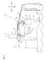
FIGS. 1 through 9 , an embodiment of a work machine according to the present invention will be described.FIG. 1 presents a side elevation of a wheel loader embodying the work machine. Thewheel loader 100 comprises afront body 110 that includes anarm 111, abucket 112,tires 113 and the like, and arear body 120 that includes an operator'scab 121, a machine compartment (engine compartment) 122,tires 123 and the like. Theengine compartment 122 is shielded with anengine hood 140 at its top and acompartment cover 130, which can be opened and closed, at a side thereof. Acounterweight 124 is attached at the rear of therear body 120. Ahydraulic oil tank 125 is disposed to the front of theengine compartment 122. - An
arm cylinder 117 drives thearm 111 so that the arm swings up/down (so that the arm is elevated/lowered), whereas thebucket 112, driven by abucket cylinder 115, swings up/down (excavates/dumps). Thefront body 110 and therear body 120 are linked to each other via acenter pin 101 so as to be able to rotate relative to each other and as asteering cylinder 116 extends/contracts, thefront body 110 articulates left/right relative to therear body 120. In order to describe the embodiment clearly, directional terms such as front, rear, left, right, up and down are used as defined in the various figures. In addition, a given drawing, in reference to which the embodiment will be described below, may not include an illustration of some members in part or in their entirety, among the members configuring thewheel loader 100, the illustration of which needs to be omitted in order to facilitate the explanation. -
FIG. 2 provides a side elevation of therear body 120 viewed from the left side, with thecompartment cover 130 disengaged from the left side surface thereof. In theengine compartment 122, anengine 301 is mounted at an engine mounting bracket (not shown) at aframe 120A of therear body 120. It is to be noted that various accessories, including an EGR (exhaust gas recirculation) cooler, are mounted at theengine 301. A supercharger (turbocharger) 302 is one of such accessories. - An exhaust
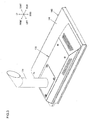
emission control device 320, suspended from theengine hood 140 and supported in this suspended state as will be described later, is disposed above theengine 301 in theengine compartment 122. As explained earlier, theengine hood 140 is disposed at the top of theengine compartment 122.FIG. 3 shows theengine hood 140 in a perspective, andFIGS. 4 and5 provide perspectives of theengine hood 140 in reference to which the installation of theengine hood 140 will be described. It is to be noted that in order to assure better clarity in the illustration,FIG. 5 does not show atop plate 141, which is part of theengine hood 140, as will be described below. Theengine hood 140 includes thetop plate 141, which shields theengine compartment 122 and reinforcingmembers 142 through 146, which reinforce theengine hood 140. In addition, anopening cover 170, which will be described in detail later, is mounted at the engine hood 140 (seeFIG. 3 ). - The
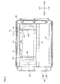
top plate 141 is a plate member having the left and right side ends thereof and the rear end thereof all bent downward. An exhaust emission controldevice installation opening 141a is formed in thetop plate 141. As will be explained later, the exhaust gas scrubbing device installation opening 141 a is formed at theengine hood 140 so as to allow the exhaustemission control device 320 to be mounted/dismounted without having to disengage theengine hood 140. AsFIG. 5 indicates, the reinforcingmembers 142 through 146 are disposed at the lower surface of thetop plate 141. - The reinforcing
member 142 is an L-shaped member that includes a frontward rangingportion 142a ranging frontward and a downward rangingportion 142b ranging downward, which intersect each other at a substantially right angle so as to form a substantially L-shaped section viewed from a side of thewheel loader 100. The reinforcingmember 142, disposed at the front end of theengine hood 140, extends along the left/right direction. The front ends of the reinforcingmembers 143 through 145, all extending along the front/rear direction, are connected to the rear surface of the downward rangingportion 142b. The reinforcingmember 143 is a right-side member that extends along the front/rear direction, whereas the reinforcingmember 144 is a left-side member that extends along the front/rear direction. The reinforcingmember 145 disposed further rightward relative to the exhaust emission control device installation opening 141a, extends along the front/rear direction without interfering with the exhaust emission controldevice installation opening 141a. The rear ends of the reinforcingmembers 143 through 145 are connected to the reinforcingmember 146, which is located at the rear end of theengine hood 140 and extends along the left/right direction. - At its front end, the
engine hood 140 is supported with the lower surface of the frontward rangingportion 142a of the reinforcingmember 142 set in contact with the upper surface of thehydraulic oil tank 125, whereas at its rear end, the reinforcingmember 146 is supported by a compartmentcover supporting member 160. The compartmentcover supporting member 160 includes a pair ofsupport posts 161, one disposed on the left side and the other disposed on the right side, each extending upright from theframe 120A of therear body 120. It is to be noted that the compartmentcover supporting member 160 provides additional strength to theengine hood 140 and, in particular, to the reinforcingmember 146. - As
FIGS. 3 and4 clearly indicate, the exhaust emission control device installation opening 141 a at thetop plate 141 of theengine hood 140 is closed off by anopening cover 170. Theopening cover 170, at which an exhaust outlet port (not shown) is formed, is detachably mounted with bolts or the like, at theengine hood 140 viabrackets 172 shown inFIG. 6 . It is to be noted thatFIG. 6 shows theengine hood 140 without theopening cover 170 in a perspective. At the exhaust outlet port formed in theopening cover 170, through which exhaust gas, having undergone a cleaning and noise reduction process in the exhaustemission control device 320, is emitted to the outside, atailpipe 171 via which the exhaust gas is discharged is mounted. The exhaust gas travels from theengine compartment 122 through thetailpipe 171 before it is emitted into the atmosphere. - In the embodiment, the height of the upper surface of the
opening cover 170 is set greater than the height of the upper surface of thetop plate 141 at theengine hood 140, as indicated inFIG. 3 . By adjusting the heights of the upper surfaces in this manner, it is ensured that theopening cover 170 and exhaust emission controldevice mounting brackets 150 do not interfere with each other. As will be explained later, the exhaust emission controldevice mounting brackets 150 are configured so that they support the exhaustemission control device 320 suspended therefrom through the exhaust emission control device installation opening 141 a at thetop plate 141. In other words, the height of theengine hood 140 is minimized outside the areal range over which it must be ensured that theengine hood 140 does not interfere with the exhaust emission controldevice mounting brackets 150 in the embodiment. These measures are taken so as to assure good rearward visibility by minimizing the height of theengine hood 140 located to the rear of the operator'scab 121. -
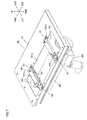
FIGS. 7 through 9 show essential components relevant to an explanation of the installation of the exhaustemission control device 320 in relation to theengine hood 140.FIG. 7 provides a perspective,FIG. 8 provides a side elevation andFIG. 9 provides a bottom view. It is to be noted thatFIG. 8 does not include an illustration of the reinforcingmember 144. As explained earlier, the exhaust emission controldevice mounting brackets 150 are brackets used to suspend the exhaustemission control device 320 from theengine hood 140 and support the exhaustemission control device 320 in the suspended state. The exhaust emission controldevice mounting brackets 150 are mounted at two locations in the embodiment, at a position near the front of the exhaustemission control device 320 and at a position near the rear of the exhaustemission control device 320. The exhaust emission controldevice mounting brackets 150 each include afastening member 151 that is fastened to theengine hood 140, amountingmember 152 that is attached to the exhaustemission control device 320 and a vibration-proofingmember 153 that is inserted between the fasteningmember 151 and the mountingmember 152 so as to absorb vibration. - The
fastening member 151 fulfills the role of a fastening portion at which the exhaust emission controldevice mounting bracket 150 is fastened to theengine hood 140. Thefastening member 151 extends along the left/right direction above the exhaust emission controldevice installation opening 141a. The right end of thefastening member 151, set above the reinforcingmember 145, and the left end of thefastening member 151, set above the reinforcingmember 144, are placed on theengine hood 140 in this state and thefastening member 151 is fastened to theengine hood 140 via, for instance,bolts 181 or the like. - The mounting
member 152 fulfills the role of a mounting portion that is attached to the exhaustemission control device 320. The mountingmember 152 includes a suspendingmember 1521 for suspending the exhaustemission control device 320 via thefastening member 151 and the vibration-proofingmember 153 and a U-bolt 1522 used to attach the exhaustemission control device 320 to a lower portion of the suspendingmember 1521. The suspendingmember 1521 includes abent portion 1521a located at the top thereof, which is bent at a substantially right angle, and a strap-like portion 1521b, which is located at a lower area, forming a circular arc so as to range along the outer circumference of the exhaustemission control device 320 assuming a substantially cylindrical shape. The exhaustemission control device 320 is held between the lower surface of the strap-like portion 1521b and theU-bolt 1522 supporting the exhaustemission control device 320 at the bottom thereof and is attached to the mountingmember 152 in this state. It is to be noted that a belt-shaped member forming a circular arc so as to range along the outer circumference of the exhaustemission control device 320 may be disposed between the exhaustemission control device 320 and theU-bolt 1522, as shown inFIGS. 8 and9 . - The vibration-proofing
member 153 includes a portion constituted of an elastic material such as rubber, which absorbs vibration, and a portion fastened to thefastening member 151 and the mountingmember 152. - As the exhaust emission control
device mounting brackets 150 structured as described above are fastened to theengine hood 140, the right ends of thefastening members 151, set above the reinforcingmember 145, and the left end of thefastening member 151, set above the reinforcingmember 144, are placed on theengine hood 140, as explained earlier. Thus, as the exhaust emission controldevice mounting brackets 150 are fastened to theengine hood 140, the exhaustemission control device 320 becomes supported by the reinforcingmembers engine hood 140 via the exhaust emission controldevice mounting brackets 150. In other words, the load of the exhaustemission control device 320 is borne by the reinforcingmembers - The front ends and the rear ends of the reinforcing
members member 142 and the reinforcingmember 146 respectively. In addition, the reinforcingmember 142 is supported with the lower surface of its frontward rangingportion 142a set in contact with the upper surface of thehydraulic oil tank 125, and the reinforcingmember 146 is supported by the compartmentcover supporting member 160. - The exhaust
emission control device 320, which assumes a substantially cylindrical shape, as described earlier, includes an oxidation catalyst portion (not shown), a DPF (diesel particulate filter) portion (not shown) and a noise reducing portion (not shown), which are connected in this order along the flow of the exhaust gas, starting from the upstream side. In the oxidation catalyst portion, an oxidation catalyst (not shown) is housed. In the DPF portion, a particulate removing filter (not shown) is housed. The noise reducing portion is configured with a device that reduces exhaust noise generated at theengine 301. Anexhaust pipe 324 is mounted at an exhaust gas outlet of the noise reducing portion. As shown inFIG. 2 , a gap is formed between theexhaust pipe 324 and thetailpipe 171 mounted at theopening cover 170. It is to be noted thatFIG. 2 also shows anexhaust pipe 325 that connects thesupercharger 302 with the exhaustemission control device 320. The exhaustemission control device 320, assuming a substantially cylindrical shape, is disposed so as to set the direction along which the axis of the cylinder extends in substantial alignment with the front/rear direction of thewheel loader 100 on the upper left side of theengine compartment 122. - When the exhaust
emission control device 320 needs to be inspected or replaced, theopening cover 170 can be disengaged from theengine hood 140, as shown inFIG. 6 , so as to expose the exhaustemission control device 320 through the exhaust emission controldevice installation opening 141a. In this state, a pressure difference sensor (not shown), which detects the pressure difference between the exhaust gas pressure on the intake side of the particulate removing filter and the exhaust gas pressure on the outlet side of the particulate removing filter, for instance, and the like can be inspected with ease. In addition, by disengaging thebrackets 172 from theengine hood 140, as shown inFIG. 7 , loosening thebolts 181 that fasten thefastening members 151 of the exhaust emission controldevice mounting brackets 150 to theengine hood 140 and disconnecting the exhaustemission control device 320 from theexhaust pipe 325, the exhaustemission control device 320 mounted at the exhaust emission controldevice mounting brackets 150 can be dismounted with ease via the exhaust emission control device installation opening 141 a without having to disengage theengine hood 140. - The
wheel loader 100 in the embodiment described above achieves the following advantages. - (1) At the
engine hood 140, with the front-end reinforcing member 142 and the rear-end reinforcing member 146 thereof respectively supported by thehydraulic oil tank 125 and the compartmentcover supporting member 160, the exhaustemission control device 320, suspended by the exhaust emission controldevice mounting brackets 150 through the exhaust emission controldevice installation opening 141a, is supported in the suspended state. Since vibration of theengine 301 is not readily transmitted to the exhaustemission control device 320 installed as described above, vibration of the exhaustemission control device 320 is minimized. As a result, malfunction of the particulate removing filter, the sensors (not shown) and the like attributable to vibration can be effectively prevented, which, in turn, makes it possible to reduce costs associated with replacement of the particulate removing filter, the sensors and the like. Moreover, an improvement in the durability and reliability of the exhaustemission control device 320 is achieved. - Furthermore, the exhaust
emission control device 320 can be installed without requiring a mount or the like at theengine 301. Thus, since a mount or the like, which would need to be installed in a very limited installation space so as not to interfere with the installation of the accessories for theengine 301, does not need to be installed, the restrictions imposed with respect to the installation position of the exhaustemission control device 320 are lessened and the installation layout for the accessories for theengine 301 can be designed with a higher level of freedom. - (2) Once the
opening cover 170 and thebrackets 172 are disengaged from theengine hood 140, thebolts 181 fastening thefastening members 151 of the exhaust emission controldevice mounting brackets 150 to theengine hood 140 are loosened and the exhaustemission control device 320 and theexhaust pipe 325 are disengaged from each other, the exhaustemission control device 320 can be dismounted with ease via the exhaust emission control device installation opening 141 a without having to disengage theengine hood 140. As a result, maintenance work on the exhaustemission control device 320 can be performed with better ease. - (3) The front end of the
engine hood 140 is supported with the lower surface of the frontward rangingportion 142a of the reinforcingmember 142 set in contact with the upper surface of thehydraulic oil tank 125. In addition, the front ends of the reinforcingmembers 143 through 145 are connected to the rear surface of the rearward rangingportion 142b of the reinforcingmember 142. Through these measures, the height of the upper surface of thetop plate 141 at theengine hood 140 can be set substantially equal to the height of the upper surface of thehydraulic oil tank 125. As a result, good rearward visibility from the operator'scab 121 is assured by minimizing the height of the upper surface of thetop plate 141 at theengine hood 140 while, at the same time, sustaining a high level of strength at theengine hood 140. - (4) The height of the upper surface of the
top plate 141 at theengine hood 140 is set smaller than the height of the upper surface of theopening cover 170. As a result, good rearward visibility from the operator'scab 121 is assured by minimizing the height of theengine hood 140 outside the areal range over which interference with the exhaust emission controldevice mounting brackets 150 must be avoided. - (5) The exhaust emission control
device mounting brackets 150 each include a vibration-proofingmember 153 disposed between the fasteningmember 151 and the mountingmember 152 to absorb vibration. Since the presence of the vibration-proofingmember 153 disallows a ready transmission of vibration from theengine hood 140 toward the exhaustemission control device 320, malfunction of the particulate removing filter, the sensors (not shown) and the like attributable to vibration is prevented so as to minimize costs associated with replacing the particulate removing filter, the sensors and the like and improve the durability and the reliability of the exhaustemission control device 320. -
- (1) While the exhaust emission control
device mounting brackets 150 are disposed at two locations, one at a position near the front of the exhaustemission control device 320 and the other at a position near the rear of the exhaustemission control device 320, in the embodiment described above, the present invention is not limited to this example. An exhaust emission controldevice mounting bracket 150 may be disposed at a single location or exhaust emission controldevice mounting brackets 150 may be disposed at three or more locations. - (2) While the vibration-proofing
member 153 is inserted between the fasteningmember 151 and the mountingmember 152 in the embodiment described above, the present invention is not limited to this example. For instance, thefastening member 151 and the mountingmember 152 may be formed as an integrated unit and in this case, an elastic member for vibration absorption may be inserted between the lower surface of thefastening member 151 and the upper surface of thetop plate 141. - (3) While the work machine according to the present invention is embodied as the
wheel loader 100 in the description provided above, the present invention may be adopted in another type of work machine such as a hydraulic excavator. - (4) The embodiment and variations thereof described above may be adopted in any combination.
- It is to be noted that the present invention is in no way limited to any of the particulars of the embodiment described above and that work machines adopting various structures, including a frame for a work machine, an engine supported by the frame inside a machine compartment of the work machine, an exhaust emission control device that includes a filter that collects particulates contained in exhaust gas discharged from the engine, a compartment cover that forms (defines) the external shape of the machine compartment, a compartment cover supporting member that supports the compartment cover and is disposed on the frame, an engine hood that includes a top plate shielding the machine compartment above the engine, an opening formed at the top plate, through which the exhaust emission control device is lifted up out of the machine compartment and a reinforcing member disposed at an edge of the opening and is load-bearing member supporting the exhaust emission control device, that includes and is supported at least by the compartment cover supporting member, an exhaust emission control device supporting member that suspends the exhaust emission control device downward through the opening and supports the exhaust emission control device in a suspended state and an opening cover detachably mounted at the engine hood, which closes off or opens up the opening, and characterized in that the exhaust emission control device supporting member includes a mounting portion that is attached to the exhaust emission control device and a fastening portion supported by and fastened to the reinforcing member, and that once the fastening portion is unfastened, the exhaust emission control device supporting member can be disengaged and removed upward and out of the opening together with the exhaust emission control device attached to the mounting portion, are all within the scope of the present invention.
- The work machine achieved in the embodiment described above includes an engine hood having a top plate shielding the machine compartment above the engine, an opening formed at the top plate, through which the exhaust emission control device is lifted up out of the machine compartment and a reinforcing member disposed at an edge of the opening and bearing the supporting load of the exhaust emission control device. The engine hood is supported by at least a compartment cover supporting member. The exhaust emission control device is suspended downward by an exhaust emission control device supporting member via the opening at the engine hood and is supported in the suspended state. These structural features make it possible to damp vibration of the exhaust emission control device, and thus, the durability and the reliability of the exhaust emission control device can be improved.
- While the embodiment and variations thereof are described above, the present invention is in no way limited to the particulars of the embodiment and the variations and any modes conceivable within the scope of the technical teachings of the present invention are also within the scope of the present invention.
- The disclosure of the following priority application is herein incorporated by reference:
Japanese Patent Application No.2011-145471 filed June 30, 2011
Claims (4)
- A work machine comprising:a frame of the work machine;an engine supported by the frame inside a machine compartment of the work machine;an exhaust emission control device including a filter that collects particulates contained in exhaust gas discharged from the engine;a compartment cover that defines the machine compartment;a compartment cover supporting member that supports the compartment cover and is disposed on the frame;an engine hood that is supported by at least the compartment cover supporting member and includes a top plate shielding the machine compartment above the engine, an opening formed at the top plate, through which the exhaust emission control device is lifted up out of the machine compartment, and a reinforcing member disposed at an edge of the opening, that bears a supporting load of the exhaust emission control device;an exhaust emission control device supporting member that suspends the exhaust emission control device downward through the opening and supports the exhaust emission control device in a suspended state; andan opening cover that is detachably mounted at the engine hood and closes off or opens up the opening, wherein:the exhaust emission control device supporting member includes a mounting portion that is attached to the exhaust emission control device and a fastening portion that is supported by, and fastened to, the reinforcing member, and when the fastening portion is unfastened, the exhaust emission control device supporting member is removable above the opening together with the exhaust emission control device attached to the mounting portion.
- A work machine according to claim 1, wherein:an L-shaped member that includes a frontward ranging portion ranging frontward and a downward ranging portion ranging downward, intersecting each other at a substantially right angle so as to form a substantially L-shaped section viewed from a side of the work machine, is disposed at a front end of the engine hood, and a front end of the reinforcing member extending along a front/rear direction is connected to a surface of the downward ranging portion located on a rear side;the front end of the engine hood is supported with a lower surface of the frontward ranging portion set in contact with an upper surface of a hydraulic oil tank; anda rear end of the engine hood is supported by the compartment cover supporting member.
- A work machine according to claim 1 or claim 2, wherein:a height of the top plate is set smaller than the height of an upper surface of the opening cover.
- A work machine according to any one of claims 1 through 3, wherein:the exhaust emission control device supporting member includes a fastening member as the fastening portion, a mounting member as the mounting portion and an elastic member disposed between the fastening member and the mounting member, and the mounting member is supported by the fastening member via the elastic member.
Applications Claiming Priority (2)
| Application Number | Priority Date | Filing Date | Title |
|---|---|---|---|
| JP2011145471A JP5508351B2 (en) | 2011-06-30 | 2011-06-30 | Work machine |
| PCT/JP2012/066774 WO2013002390A1 (en) | 2011-06-30 | 2012-06-29 | Working machine |
Publications (3)
| Publication Number | Publication Date |
|---|---|
| EP2728075A1 true EP2728075A1 (en) | 2014-05-07 |
| EP2728075A4 EP2728075A4 (en) | 2015-03-11 |
| EP2728075B1 EP2728075B1 (en) | 2018-02-21 |
Family
ID=47424275
Family Applications (1)
| Application Number | Title | Priority Date | Filing Date |
|---|---|---|---|
| EP12805151.3A Active EP2728075B1 (en) | 2011-06-30 | 2012-06-29 | Working machine |
Country Status (5)
| Country | Link |
|---|---|
| US (1) | US9056547B2 (en) |
| EP (1) | EP2728075B1 (en) |
| JP (1) | JP5508351B2 (en) |
| CN (1) | CN103649422B (en) |
| WO (1) | WO2013002390A1 (en) |
Cited By (2)
| Publication number | Priority date | Publication date | Assignee | Title |
|---|---|---|---|---|
| EP3020872A3 (en) * | 2014-11-17 | 2016-06-01 | Kobelco Construction Machinery Co., Ltd. | Construction machine |
| EP3178998A4 (en) * | 2014-09-03 | 2018-04-04 | Shantui Construction Machinery Co., Ltd. | Bulldozer |
Families Citing this family (17)
| Publication number | Priority date | Publication date | Assignee | Title |
|---|---|---|---|---|
| GB2466483A (en) * | 2008-12-19 | 2010-06-30 | Agco Gmbh & Co | A vertical exhaust system for a vehicle |
| JP5731426B2 (en) * | 2012-02-28 | 2015-06-10 | 日立建機株式会社 | Work machine |
| JP5882158B2 (en) * | 2012-07-26 | 2016-03-09 | ヤンマー株式会社 | Engine equipment |
| WO2014024929A1 (en) * | 2012-08-08 | 2014-02-13 | ヤンマー株式会社 | Engine device for mounting on working machine |
| US9097168B2 (en) * | 2012-08-23 | 2015-08-04 | Electro-Motive Diesel, Inc. | Bracket for an after-treatment component |
| US9353502B2 (en) * | 2012-10-26 | 2016-05-31 | Komatsu Ltd. | Wheel loader |
| US9033095B2 (en) | 2013-02-15 | 2015-05-19 | Komatsu Ltd. | Exhaust treatment unit, manufacturing method of exhaust treatment unit, and work vehicle |
| CN104302844B (en) * | 2013-02-22 | 2016-01-20 | 株式会社小松制作所 | Wheel loader |
| JP6262440B2 (en) * | 2013-04-08 | 2018-01-17 | 株式会社Kcm | Wheel loader |
| JP6120689B2 (en) * | 2013-06-14 | 2017-04-26 | ヤンマー株式会社 | Tractor |
| JP6170848B2 (en) * | 2014-02-28 | 2017-07-26 | 日立住友重機械建機クレーン株式会社 | Construction machinery |
| CN104153409B (en) * | 2014-09-03 | 2016-08-24 | 山推工程机械股份有限公司 | A kind of bull-dozer |
| JP6438341B2 (en) * | 2014-10-15 | 2018-12-12 | ヤンマー株式会社 | Work vehicle |
| JP6440453B2 (en) * | 2014-10-29 | 2018-12-19 | 日立建機株式会社 | Heat insulation structure of rolling machine |
| CN105109557A (en) * | 2015-08-07 | 2015-12-02 | 力士德工程机械股份有限公司 | Excavator covering part supporting framework |
| US10800225B2 (en) * | 2016-08-03 | 2020-10-13 | Komatsu Ltd. | Working vehicle |
| CN113665681B (en) * | 2021-08-23 | 2022-07-22 | 广东皓耘科技有限公司 | Installing support and tractor |
Family Cites Families (19)
| Publication number | Priority date | Publication date | Assignee | Title |
|---|---|---|---|---|
| US4131172A (en) * | 1977-07-11 | 1978-12-26 | Caterpillar Tractor Co. | Access panel for enclosures |
| JP2002021565A (en) * | 2000-07-11 | 2002-01-23 | Komatsu Ltd | Engine enclosure for construction vehicle |
| JP3952972B2 (en) * | 2003-03-07 | 2007-08-01 | コベルコ建機株式会社 | Construction machine cooling system |
| JP4539133B2 (en) * | 2004-03-01 | 2010-09-08 | コベルコ建機株式会社 | Exhaust structure of construction machinery |
| US20080006460A1 (en) * | 2006-07-05 | 2008-01-10 | Mario Giovannini | Hood assembly for a machine and a method of use thereof |
| US7717205B2 (en) * | 2006-11-28 | 2010-05-18 | Caterpillar Inc. | Engine hood assembly enclosure with exhaust aftertreatment device integrated therein, and machine using same |
| ATE522671T1 (en) * | 2006-11-28 | 2011-09-15 | Hitachi Construction Machinery | CONSTRUCTION MACHINERY |
| WO2008136203A1 (en) * | 2007-05-01 | 2008-11-13 | Hitachi Construction Machinery Co., Ltd. | Construction machine |
| JP4900163B2 (en) | 2007-09-26 | 2012-03-21 | コベルコ建機株式会社 | Construction machinery |
| JP5101324B2 (en) * | 2008-02-07 | 2012-12-19 | 日立建機株式会社 | Arrangement structure of NOx reduction device for construction machinery |
| JP5172381B2 (en) * | 2008-02-22 | 2013-03-27 | 日立建機株式会社 | Construction machinery |
| WO2009142058A1 (en) * | 2008-05-22 | 2009-11-26 | 日立建機株式会社 | Construction machine |
| KR101539130B1 (en) | 2008-07-10 | 2015-07-23 | 히다찌 겐끼 가부시키가이샤 | Construction machine |
| JP5026393B2 (en) | 2008-10-30 | 2012-09-12 | 住友建機株式会社 | Construction machine muffler installation structure |
| JP5169766B2 (en) * | 2008-11-20 | 2013-03-27 | コベルコ建機株式会社 | Muffler mounting device for construction machinery |
| JP4981016B2 (en) | 2008-12-12 | 2012-07-18 | 日立建機株式会社 | Exhaust gas purification device |
| JP2010215122A (en) * | 2009-03-17 | 2010-09-30 | Hitachi Constr Mach Co Ltd | Engine cover for construction machine |
| JP5178923B2 (en) * | 2010-01-26 | 2013-04-10 | 株式会社小松製作所 | Engine hood for construction machinery |
| JP5033226B2 (en) * | 2010-08-02 | 2012-09-26 | 株式会社小松製作所 | Work vehicle |
-
2011
- 2011-06-30 JP JP2011145471A patent/JP5508351B2/en active Active
-
2012
- 2012-06-29 WO PCT/JP2012/066774 patent/WO2013002390A1/en active Application Filing
- 2012-06-29 US US14/128,361 patent/US9056547B2/en active Active
- 2012-06-29 EP EP12805151.3A patent/EP2728075B1/en active Active
- 2012-06-29 CN CN201280031136.8A patent/CN103649422B/en active Active
Cited By (3)
| Publication number | Priority date | Publication date | Assignee | Title |
|---|---|---|---|---|
| EP3178998A4 (en) * | 2014-09-03 | 2018-04-04 | Shantui Construction Machinery Co., Ltd. | Bulldozer |
| EP3020872A3 (en) * | 2014-11-17 | 2016-06-01 | Kobelco Construction Machinery Co., Ltd. | Construction machine |
| US9657459B2 (en) | 2014-11-17 | 2017-05-23 | Kobelco Construction Machinery Co., Ltd. | Construction machine |
Also Published As
| Publication number | Publication date |
|---|---|
| EP2728075A4 (en) | 2015-03-11 |
| CN103649422B (en) | 2016-03-09 |
| WO2013002390A1 (en) | 2013-01-03 |
| US20140124285A1 (en) | 2014-05-08 |
| CN103649422A (en) | 2014-03-19 |
| US9056547B2 (en) | 2015-06-16 |
| JP2013011126A (en) | 2013-01-17 |
| JP5508351B2 (en) | 2014-05-28 |
| EP2728075B1 (en) | 2018-02-21 |
Similar Documents
| Publication | Publication Date | Title |
|---|---|---|
| EP2728075B1 (en) | Working machine | |
| EP2746464B1 (en) | Wheel loader | |
| JP5641984B2 (en) | Work machine | |
| US8997915B2 (en) | Wheel loader | |
| KR101495587B1 (en) | Exhaust treatment unit | |
| JP5382669B1 (en) | Excavator | |
| WO2014125622A1 (en) | Hydraulic shovel | |
| CN103374934B (en) | Bulldozer | |
| KR20120088764A (en) | Work vehicle | |
| JP5676827B1 (en) | Support mechanism, exhaust treatment unit, wheel loader | |
| JP5501424B2 (en) | Exhaust treatment unit | |
| EP3020872B1 (en) | Construction machine | |
| KR20150013220A (en) | Hydraulic shovel | |
| JP5414871B1 (en) | Excavator | |
| JP5325357B1 (en) | Wheel loader | |
| JP2020157866A (en) | Work vehicle | |
| US9809954B2 (en) | Bulldozer |
Legal Events
| Date | Code | Title | Description |
|---|---|---|---|
| PUAI | Public reference made under article 153(3) epc to a published international application that has entered the european phase |
Free format text: ORIGINAL CODE: 0009012 |
|
| 17P | Request for examination filed |
Effective date: 20140130 |
|
| AK | Designated contracting states |
Kind code of ref document: A1 Designated state(s): AL AT BE BG CH CY CZ DE DK EE ES FI FR GB GR HR HU IE IS IT LI LT LU LV MC MK MT NL NO PL PT RO RS SE SI SK SM TR |
|
| DAX | Request for extension of the european patent (deleted) | ||
| A4 | Supplementary search report drawn up and despatched |
Effective date: 20150206 |
|
| RIC1 | Information provided on ipc code assigned before grant |
Ipc: B60K 13/04 20060101ALI20150202BHEP Ipc: F01N 3/28 20060101ALI20150202BHEP Ipc: F01N 3/021 20060101ALI20150202BHEP Ipc: E02F 3/34 20060101ALI20150202BHEP Ipc: F01N 13/18 20100101ALI20150202BHEP Ipc: F01N 13/08 20100101ALI20150202BHEP Ipc: E02F 9/00 20060101AFI20150202BHEP Ipc: E02F 9/08 20060101ALI20150202BHEP |
|
| RAP1 | Party data changed (applicant data changed or rights of an application transferred) |
Owner name: KCM CORPORATION |
|
| GRAP | Despatch of communication of intention to grant a patent |
Free format text: ORIGINAL CODE: EPIDOSNIGR1 |
|
| INTG | Intention to grant announced |
Effective date: 20171106 |
|
| GRAS | Grant fee paid |
Free format text: ORIGINAL CODE: EPIDOSNIGR3 |
|
| GRAA | (expected) grant |
Free format text: ORIGINAL CODE: 0009210 |
|
| AK | Designated contracting states |
Kind code of ref document: B1 Designated state(s): AL AT BE BG CH CY CZ DE DK EE ES FI FR GB GR HR HU IE IS IT LI LT LU LV MC MK MT NL NO PL PT RO RS SE SI SK SM TR |
|
| REG | Reference to a national code |
Ref country code: GB Ref legal event code: FG4D |
|
| RIN1 | Information on inventor provided before grant (corrected) |
Inventor name: KIMIJIMA, KOUJI Inventor name: AKUTSU, YUUJI |
|
| REG | Reference to a national code |
Ref country code: CH Ref legal event code: EP |
|
| REG | Reference to a national code |
Ref country code: AT Ref legal event code: REF Ref document number: 971864 Country of ref document: AT Kind code of ref document: T Effective date: 20180315 |
|
| REG | Reference to a national code |
Ref country code: IE Ref legal event code: FG4D |
|
| REG | Reference to a national code |
Ref country code: DE Ref legal event code: R096 Ref document number: 602012043114 Country of ref document: DE |
|
| REG | Reference to a national code |
Ref country code: SE Ref legal event code: TRGR |
|
| REG | Reference to a national code |
Ref country code: NL Ref legal event code: MP Effective date: 20180221 |
|
| REG | Reference to a national code |
Ref country code: LT Ref legal event code: MG4D |
|
| REG | Reference to a national code |
Ref country code: AT Ref legal event code: MK05 Ref document number: 971864 Country of ref document: AT Kind code of ref document: T Effective date: 20180221 |
|
| PG25 | Lapsed in a contracting state [announced via postgrant information from national office to epo] |
Ref country code: ES Free format text: LAPSE BECAUSE OF FAILURE TO SUBMIT A TRANSLATION OF THE DESCRIPTION OR TO PAY THE FEE WITHIN THE PRESCRIBED TIME-LIMIT Effective date: 20180221 Ref country code: NL Free format text: LAPSE BECAUSE OF FAILURE TO SUBMIT A TRANSLATION OF THE DESCRIPTION OR TO PAY THE FEE WITHIN THE PRESCRIBED TIME-LIMIT Effective date: 20180221 Ref country code: HR Free format text: LAPSE BECAUSE OF FAILURE TO SUBMIT A TRANSLATION OF THE DESCRIPTION OR TO PAY THE FEE WITHIN THE PRESCRIBED TIME-LIMIT Effective date: 20180221 Ref country code: LT Free format text: LAPSE BECAUSE OF FAILURE TO SUBMIT A TRANSLATION OF THE DESCRIPTION OR TO PAY THE FEE WITHIN THE PRESCRIBED TIME-LIMIT Effective date: 20180221 Ref country code: NO Free format text: LAPSE BECAUSE OF FAILURE TO SUBMIT A TRANSLATION OF THE DESCRIPTION OR TO PAY THE FEE WITHIN THE PRESCRIBED TIME-LIMIT Effective date: 20180521 Ref country code: FI Free format text: LAPSE BECAUSE OF FAILURE TO SUBMIT A TRANSLATION OF THE DESCRIPTION OR TO PAY THE FEE WITHIN THE PRESCRIBED TIME-LIMIT Effective date: 20180221 Ref country code: CY Free format text: LAPSE BECAUSE OF FAILURE TO SUBMIT A TRANSLATION OF THE DESCRIPTION OR TO PAY THE FEE WITHIN THE PRESCRIBED TIME-LIMIT Effective date: 20180221 |
|
| PG25 | Lapsed in a contracting state [announced via postgrant information from national office to epo] |
Ref country code: LV Free format text: LAPSE BECAUSE OF FAILURE TO SUBMIT A TRANSLATION OF THE DESCRIPTION OR TO PAY THE FEE WITHIN THE PRESCRIBED TIME-LIMIT Effective date: 20180221 Ref country code: GR Free format text: LAPSE BECAUSE OF FAILURE TO SUBMIT A TRANSLATION OF THE DESCRIPTION OR TO PAY THE FEE WITHIN THE PRESCRIBED TIME-LIMIT Effective date: 20180522 Ref country code: AT Free format text: LAPSE BECAUSE OF FAILURE TO SUBMIT A TRANSLATION OF THE DESCRIPTION OR TO PAY THE FEE WITHIN THE PRESCRIBED TIME-LIMIT Effective date: 20180221 Ref country code: RS Free format text: LAPSE BECAUSE OF FAILURE TO SUBMIT A TRANSLATION OF THE DESCRIPTION OR TO PAY THE FEE WITHIN THE PRESCRIBED TIME-LIMIT Effective date: 20180221 Ref country code: BG Free format text: LAPSE BECAUSE OF FAILURE TO SUBMIT A TRANSLATION OF THE DESCRIPTION OR TO PAY THE FEE WITHIN THE PRESCRIBED TIME-LIMIT Effective date: 20180521 |
|
| PG25 | Lapsed in a contracting state [announced via postgrant information from national office to epo] |
Ref country code: RO Free format text: LAPSE BECAUSE OF FAILURE TO SUBMIT A TRANSLATION OF THE DESCRIPTION OR TO PAY THE FEE WITHIN THE PRESCRIBED TIME-LIMIT Effective date: 20180221 Ref country code: AL Free format text: LAPSE BECAUSE OF FAILURE TO SUBMIT A TRANSLATION OF THE DESCRIPTION OR TO PAY THE FEE WITHIN THE PRESCRIBED TIME-LIMIT Effective date: 20180221 Ref country code: PL Free format text: LAPSE BECAUSE OF FAILURE TO SUBMIT A TRANSLATION OF THE DESCRIPTION OR TO PAY THE FEE WITHIN THE PRESCRIBED TIME-LIMIT Effective date: 20180221 Ref country code: EE Free format text: LAPSE BECAUSE OF FAILURE TO SUBMIT A TRANSLATION OF THE DESCRIPTION OR TO PAY THE FEE WITHIN THE PRESCRIBED TIME-LIMIT Effective date: 20180221 |
|
| PGFP | Annual fee paid to national office [announced via postgrant information from national office to epo] |
Ref country code: IT Payment date: 20180622 Year of fee payment: 7 |
|
| REG | Reference to a national code |
Ref country code: DE Ref legal event code: R097 Ref document number: 602012043114 Country of ref document: DE |
|
| PG25 | Lapsed in a contracting state [announced via postgrant information from national office to epo] |
Ref country code: DK Free format text: LAPSE BECAUSE OF FAILURE TO SUBMIT A TRANSLATION OF THE DESCRIPTION OR TO PAY THE FEE WITHIN THE PRESCRIBED TIME-LIMIT Effective date: 20180221 Ref country code: SM Free format text: LAPSE BECAUSE OF FAILURE TO SUBMIT A TRANSLATION OF THE DESCRIPTION OR TO PAY THE FEE WITHIN THE PRESCRIBED TIME-LIMIT Effective date: 20180221 Ref country code: CZ Free format text: LAPSE BECAUSE OF FAILURE TO SUBMIT A TRANSLATION OF THE DESCRIPTION OR TO PAY THE FEE WITHIN THE PRESCRIBED TIME-LIMIT Effective date: 20180221 Ref country code: SK Free format text: LAPSE BECAUSE OF FAILURE TO SUBMIT A TRANSLATION OF THE DESCRIPTION OR TO PAY THE FEE WITHIN THE PRESCRIBED TIME-LIMIT Effective date: 20180221 |
|
| PLBE | No opposition filed within time limit |
Free format text: ORIGINAL CODE: 0009261 |
|
| STAA | Information on the status of an ep patent application or granted ep patent |
Free format text: STATUS: NO OPPOSITION FILED WITHIN TIME LIMIT |
|
| 26N | No opposition filed |
Effective date: 20181122 |
|
| REG | Reference to a national code |
Ref country code: CH Ref legal event code: PL |
|
| GBPC | Gb: european patent ceased through non-payment of renewal fee |
Effective date: 20180629 |
|
| PG25 | Lapsed in a contracting state [announced via postgrant information from national office to epo] |
Ref country code: SI Free format text: LAPSE BECAUSE OF FAILURE TO SUBMIT A TRANSLATION OF THE DESCRIPTION OR TO PAY THE FEE WITHIN THE PRESCRIBED TIME-LIMIT Effective date: 20180221 |
|
| REG | Reference to a national code |
Ref country code: BE Ref legal event code: MM Effective date: 20180630 |
|
| PG25 | Lapsed in a contracting state [announced via postgrant information from national office to epo] |
Ref country code: LU Free format text: LAPSE BECAUSE OF NON-PAYMENT OF DUE FEES Effective date: 20180629 Ref country code: MC Free format text: LAPSE BECAUSE OF FAILURE TO SUBMIT A TRANSLATION OF THE DESCRIPTION OR TO PAY THE FEE WITHIN THE PRESCRIBED TIME-LIMIT Effective date: 20180221 |
|
| REG | Reference to a national code |
Ref country code: IE Ref legal event code: MM4A |
|
| PG25 | Lapsed in a contracting state [announced via postgrant information from national office to epo] |
Ref country code: GB Free format text: LAPSE BECAUSE OF NON-PAYMENT OF DUE FEES Effective date: 20180629 Ref country code: CH Free format text: LAPSE BECAUSE OF NON-PAYMENT OF DUE FEES Effective date: 20180630 Ref country code: IE Free format text: LAPSE BECAUSE OF NON-PAYMENT OF DUE FEES Effective date: 20180629 Ref country code: FR Free format text: LAPSE BECAUSE OF NON-PAYMENT OF DUE FEES Effective date: 20180630 Ref country code: LI Free format text: LAPSE BECAUSE OF NON-PAYMENT OF DUE FEES Effective date: 20180630 |
|
| PG25 | Lapsed in a contracting state [announced via postgrant information from national office to epo] |
Ref country code: BE Free format text: LAPSE BECAUSE OF NON-PAYMENT OF DUE FEES Effective date: 20180630 |
|
| REG | Reference to a national code |
Ref country code: DE Ref legal event code: R082 Ref document number: 602012043114 Country of ref document: DE Representative=s name: MERH-IP MATIAS ERNY REICHL HOFFMANN PATENTANWA, DE Ref country code: DE Ref legal event code: R081 Ref document number: 602012043114 Country of ref document: DE Owner name: HITACHI CONSTRUCTION MACHINERY CO., LTD., JP Free format text: FORMER OWNER: KCM CORP., HYOGO, JP |
|
| PG25 | Lapsed in a contracting state [announced via postgrant information from national office to epo] |
Ref country code: MT Free format text: LAPSE BECAUSE OF NON-PAYMENT OF DUE FEES Effective date: 20180629 |
|
| PG25 | Lapsed in a contracting state [announced via postgrant information from national office to epo] |
Ref country code: TR Free format text: LAPSE BECAUSE OF FAILURE TO SUBMIT A TRANSLATION OF THE DESCRIPTION OR TO PAY THE FEE WITHIN THE PRESCRIBED TIME-LIMIT Effective date: 20180221 |
|
| PG25 | Lapsed in a contracting state [announced via postgrant information from national office to epo] |
Ref country code: IT Free format text: LAPSE BECAUSE OF NON-PAYMENT OF DUE FEES Effective date: 20190629 |
|
| PG25 | Lapsed in a contracting state [announced via postgrant information from national office to epo] |
Ref country code: PT Free format text: LAPSE BECAUSE OF FAILURE TO SUBMIT A TRANSLATION OF THE DESCRIPTION OR TO PAY THE FEE WITHIN THE PRESCRIBED TIME-LIMIT Effective date: 20180221 Ref country code: HU Free format text: LAPSE BECAUSE OF FAILURE TO SUBMIT A TRANSLATION OF THE DESCRIPTION OR TO PAY THE FEE WITHIN THE PRESCRIBED TIME-LIMIT; INVALID AB INITIO Effective date: 20120629 |
|
| PG25 | Lapsed in a contracting state [announced via postgrant information from national office to epo] |
Ref country code: MK Free format text: LAPSE BECAUSE OF NON-PAYMENT OF DUE FEES Effective date: 20180221 |
|
| PG25 | Lapsed in a contracting state [announced via postgrant information from national office to epo] |
Ref country code: IS Free format text: LAPSE BECAUSE OF FAILURE TO SUBMIT A TRANSLATION OF THE DESCRIPTION OR TO PAY THE FEE WITHIN THE PRESCRIBED TIME-LIMIT Effective date: 20180621 |
|
| PGFP | Annual fee paid to national office [announced via postgrant information from national office to epo] |
Ref country code: DE Payment date: 20230502 Year of fee payment: 12 |
|
| PGFP | Annual fee paid to national office [announced via postgrant information from national office to epo] |
Ref country code: SE Payment date: 20230510 Year of fee payment: 12 |