EP2728060A1 - Wandmontierte trommelwaschmaschine - Google Patents
Wandmontierte trommelwaschmaschine Download PDFInfo
- Publication number
- EP2728060A1 EP2728060A1 EP12855802.0A EP12855802A EP2728060A1 EP 2728060 A1 EP2728060 A1 EP 2728060A1 EP 12855802 A EP12855802 A EP 12855802A EP 2728060 A1 EP2728060 A1 EP 2728060A1
- Authority
- EP
- European Patent Office
- Prior art keywords
- wall
- tub
- washing machine
- drum type
- type washing
- Prior art date
- Legal status (The legal status is an assumption and is not a legal conclusion. Google has not performed a legal analysis and makes no representation as to the accuracy of the status listed.)
- Granted
Links
- 238000005406 washing Methods 0.000 title claims abstract description 152
- XLYOFNOQVPJJNP-UHFFFAOYSA-N water Substances O XLYOFNOQVPJJNP-UHFFFAOYSA-N 0.000 claims abstract description 127
- 230000008878 coupling Effects 0.000 claims description 33
- 238000010168 coupling process Methods 0.000 claims description 33
- 238000005859 coupling reaction Methods 0.000 claims description 33
- 230000006698 induction Effects 0.000 claims description 31
- 238000013016 damping Methods 0.000 description 5
- 230000005540 biological transmission Effects 0.000 description 4
- 238000010586 diagram Methods 0.000 description 4
- 238000003780 insertion Methods 0.000 description 4
- 230000037431 insertion Effects 0.000 description 4
- 238000000034 method Methods 0.000 description 3
- 239000003599 detergent Substances 0.000 description 2
- 230000000694 effects Effects 0.000 description 2
- 238000001746 injection moulding Methods 0.000 description 2
- 238000009434 installation Methods 0.000 description 2
- 238000004519 manufacturing process Methods 0.000 description 2
- 238000000465 moulding Methods 0.000 description 2
- 238000007789 sealing Methods 0.000 description 2
- 238000009736 wetting Methods 0.000 description 2
- 238000007792 addition Methods 0.000 description 1
- 230000002411 adverse Effects 0.000 description 1
- 230000003111 delayed effect Effects 0.000 description 1
- 239000013013 elastic material Substances 0.000 description 1
- 239000000463 material Substances 0.000 description 1
- 238000012986 modification Methods 0.000 description 1
- 230000004048 modification Effects 0.000 description 1
- 230000001737 promoting effect Effects 0.000 description 1
- 239000000243 solution Substances 0.000 description 1
- 238000006467 substitution reaction Methods 0.000 description 1
- 229920003002 synthetic resin Polymers 0.000 description 1
- 239000000057 synthetic resin Substances 0.000 description 1
Images


Classifications
-
- D—TEXTILES; PAPER
- D06—TREATMENT OF TEXTILES OR THE LIKE; LAUNDERING; FLEXIBLE MATERIALS NOT OTHERWISE PROVIDED FOR
- D06F—LAUNDERING, DRYING, IRONING, PRESSING OR FOLDING TEXTILE ARTICLES
- D06F37/00—Details specific to washing machines covered by groups D06F21/00 - D06F25/00
- D06F37/26—Casings; Tubs
- D06F37/267—Tubs specially adapted for mounting thereto components or devices not provided for in preceding subgroups
-
- D—TEXTILES; PAPER
- D06—TREATMENT OF TEXTILES OR THE LIKE; LAUNDERING; FLEXIBLE MATERIALS NOT OTHERWISE PROVIDED FOR
- D06F—LAUNDERING, DRYING, IRONING, PRESSING OR FOLDING TEXTILE ARTICLES
- D06F37/00—Details specific to washing machines covered by groups D06F21/00 - D06F25/00
- D06F37/26—Casings; Tubs
- D06F37/261—Tubs made by a specially selected manufacturing process or characterised by their assembly from elements
- D06F37/262—Tubs made by a specially selected manufacturing process or characterised by their assembly from elements made of plastic material, e.g. by injection moulding
-
- D—TEXTILES; PAPER
- D06—TREATMENT OF TEXTILES OR THE LIKE; LAUNDERING; FLEXIBLE MATERIALS NOT OTHERWISE PROVIDED FOR
- D06F—LAUNDERING, DRYING, IRONING, PRESSING OR FOLDING TEXTILE ARTICLES
- D06F37/00—Details specific to washing machines covered by groups D06F21/00 - D06F25/00
- D06F37/26—Casings; Tubs
- D06F37/266—Gaskets mounted between tub and casing around the loading opening
-
- D—TEXTILES; PAPER
- D06—TREATMENT OF TEXTILES OR THE LIKE; LAUNDERING; FLEXIBLE MATERIALS NOT OTHERWISE PROVIDED FOR
- D06F—LAUNDERING, DRYING, IRONING, PRESSING OR FOLDING TEXTILE ARTICLES
- D06F39/00—Details of washing machines not specific to a single type of machines covered by groups D06F9/00 - D06F27/00
- D06F39/08—Liquid supply or discharge arrangements
- D06F39/088—Liquid supply arrangements
-
- D—TEXTILES; PAPER
- D06—TREATMENT OF TEXTILES OR THE LIKE; LAUNDERING; FLEXIBLE MATERIALS NOT OTHERWISE PROVIDED FOR
- D06F—LAUNDERING, DRYING, IRONING, PRESSING OR FOLDING TEXTILE ARTICLES
- D06F37/00—Details specific to washing machines covered by groups D06F21/00 - D06F25/00
- D06F37/20—Mountings, e.g. resilient mountings, for the rotary receptacle, motor, tub or casing; Preventing or damping vibrations
- D06F37/22—Mountings, e.g. resilient mountings, for the rotary receptacle, motor, tub or casing; Preventing or damping vibrations in machines with a receptacle rotating or oscillating about a horizontal axis
-
- D—TEXTILES; PAPER
- D06—TREATMENT OF TEXTILES OR THE LIKE; LAUNDERING; FLEXIBLE MATERIALS NOT OTHERWISE PROVIDED FOR
- D06F—LAUNDERING, DRYING, IRONING, PRESSING OR FOLDING TEXTILE ARTICLES
- D06F37/00—Details specific to washing machines covered by groups D06F21/00 - D06F25/00
- D06F37/26—Casings; Tubs
- D06F37/261—Tubs made by a specially selected manufacturing process or characterised by their assembly from elements
- D06F37/263—Tubs made by a specially selected manufacturing process or characterised by their assembly from elements assembled from at least two elements connected to each other; Connecting or sealing means therefor
-
- D—TEXTILES; PAPER
- D06—TREATMENT OF TEXTILES OR THE LIKE; LAUNDERING; FLEXIBLE MATERIALS NOT OTHERWISE PROVIDED FOR
- D06F—LAUNDERING, DRYING, IRONING, PRESSING OR FOLDING TEXTILE ARTICLES
- D06F39/00—Details of washing machines not specific to a single type of machines covered by groups D06F9/00 - D06F27/00
- D06F39/04—Heating arrangements
-
- D—TEXTILES; PAPER
- D06—TREATMENT OF TEXTILES OR THE LIKE; LAUNDERING; FLEXIBLE MATERIALS NOT OTHERWISE PROVIDED FOR
- D06F—LAUNDERING, DRYING, IRONING, PRESSING OR FOLDING TEXTILE ARTICLES
- D06F39/00—Details of washing machines not specific to a single type of machines covered by groups D06F9/00 - D06F27/00
- D06F39/12—Casings; Tubs
-
- Y—GENERAL TAGGING OF NEW TECHNOLOGICAL DEVELOPMENTS; GENERAL TAGGING OF CROSS-SECTIONAL TECHNOLOGIES SPANNING OVER SEVERAL SECTIONS OF THE IPC; TECHNICAL SUBJECTS COVERED BY FORMER USPC CROSS-REFERENCE ART COLLECTIONS [XRACs] AND DIGESTS
- Y10—TECHNICAL SUBJECTS COVERED BY FORMER USPC
- Y10T—TECHNICAL SUBJECTS COVERED BY FORMER US CLASSIFICATION
- Y10T29/00—Metal working
- Y10T29/49—Method of mechanical manufacture
- Y10T29/49826—Assembling or joining
Definitions
- the present invention relates to a wall-mounted drum type washing machine, and more particularly, to a wall-mounted drum washing that has a small size and weight so as to be stably mounted on the wall, that may reduce vibrations and noise, and that includes parts that are easily attached and detached.
- a wall-mounted drum type washing machine may be used in a narrow space, and may be used when it is mounted on the wall.
- the wall-mounted drum type washing machine includes a washing machine body and a door which is installed at the front of the washing machine body so as to be opened/closed.
- the washing machine body forms the exterior of the washing machine, and may be divided into an intermediate case, a rear case, and a front case.
- the washing machine body includes a cylindrical tub therein.
- the tub includes a drum therein that rotates.
- the drum is rotated by power of a forward/reverse motor inside the washing machine body.
- the drum has a pulley on a shaft that is, in turn, attached to the drum, and the forward/reverse motor also has a pulley on a shaft that is generally driven by the motor.
- the respective pulleys are connected through a power transmission belt to transmit power.
- the drum has a smaller depth than the diameter thereof. Therefore, the front-to-rear length of the washing machine body may be set to a small value.
- the washing machine body has a key input unit on the front surface thereof, that is, the front case. Therefore, when the washing machine body is mounted on the wall or installed at a predetermined height from the bottom surface using a table or the like, a user may easily manipulate the key input unit.
- the conventional drum type washing machine includes a tub installed in a cabinet. Therefore, since a separate member is required to support the tub inside the cabinet, it is difficult to reduce the size of the wall-mounted drum type washing machine. Accordingly, the wall-mounted drum type washing machine cannot be installed in certain places.
- the conventional wall-mounted drum type washing machine includes a driving unit installed in the cabinet. Therefore, since valuable internal space of the cabinet is occupied by the driving unit, there are difficulties in reducing the size of the conventional wall-mounted drum type washing machine.
- the conventional wall-mounted drum type washing machine includes a power transmission unit installed between the motor and the drum. Therefore, as the power transmission unit occupies space between the motor and the drum, there are difficulties in reducing the size of the conventional wall-mounted drum type washing machine.
- the tub has a cylindrical shape, but the cabinet has a hexahedral shape. Therefore, space remains in the cabinet. Therefore, it may be difficult to reduce the size of the wall-mounted drum type washing machine, and the wall-mounted drum type washing machine cannot be installed in certain spaces.
- the conventional wall-mounted drum type washing machine includes a drain pipe connected to the rear surface of the cabinet so as to drain wash water. As a result, there can be difficulties in installing the conventional wall-mounted drum type washing machine in certain spaces.
- the conventional wall-mounted drum type washing machine does not include a heater therein. Therefore, the conventional wall-mounted drum type washing machine cannot perform a hot water washing operation.
- the conventional wall-mounted drum type washing machine has a complex sealing structure to cover a gap between the tub and the opening of the cabinet over which the door is installed. Therefore, there may be difficulties in reducing the number of parts and the size of the conventional wall-mounted drum type washing machine.
- the present invention is conceived and/or created to solve such problems of the related art, and an aspect of the invention is to provide a wall-mounted drum type washing machine which has a small size and weight, that is stably mounted on the wall, that may reduce vibrations and noise, and that includes parts that are easily attached and detached.
- Another aspect of the invention is to provide a wall-mounted drum type washing machine that may be directly mounted on the wall surface and that reduces or minimizes protrusion(s) in the front of the washing machine.
- the wall-mounted drum type washing machine includes a rear panel forming a rear surface of a cabinet, configured to be mounted on a wall surface; a tub installed in the cabinet so as to contain wash water, integrated with the rear panel, and having a rotatable drum therein; a box unit connected to a cover unit having a door thereon, forming an outer wall of the cabinet, and coupled to the rear panel and surrounding the tub; a water supply device configured to supply wash water into the tub through the top surface of the cabinet; and a drain device configured to discharge wash water from the tub to the bottom of the box unit, wherein the water supply device is installed on the rear panel, and a driving unit is installed on the rear panel and configured to provide power for washing operations.
- the wall-mounted drum type washing machine may further include a gasket having one end coupled to the tub and another end in contact with the door, configured to prevent leakage of wash water to close a gap between the cabinet and the tub.
- the tub may have a mounting hole into which the gasket is inserted and a lock portion which is formed to protrude from an outer circumferential surface of the tub and to which the gasket is locked and fixed, wherein the lock portion comprises: a coupling protrusion that protrudes from an outer circumferential surface of the tub; and a lock protrusion extending from an end of the coupling protrusion in a lateral direction.
- the gasket may include a hooked body on an inside of the lock portion and surrounding outer walls of the coupling protrusion and the lock protrusion; a passing body protruding to the outside of the tub through the mounting hole and connected to the hooked body; a coupling body connected to the passing body and in contact with the door; and a ring spring in an end of the hooked body configured to attach the hooked body to the tub.
- the water supply device may have a water supply pipe on a top or upper surface of the rear panel, configured to supply wash water to the tub through the rear panel.
- the rear panel may have a concave mounting groove on a rear surface thereof, forming a space between the wall surface and the rear surface of the rear panel, and the driving unit is connected to the drum through the rear panel and is in the mounting groove.
- the water supply pipe may be in a connection portion formed by cutting the top circumference of the mounting groove, and has an upper end protruding from a top surface of the connection portion and a lower end connected to a rear surface of the tub, and the wall-mounted drum type washing machine further comprises: a water supply valve connected to the water supply pipe in the connection portion, and a cover on the connection portion that covers the water supply valve.
- the drain device may include a first drain pipe at a bottom of the tub, configured to discharge wash water; a second drain pipe under the first drain pipe and having a larger diameter than the first drain pipe; and a siphon positioned between the first and second drain pipes and connecting the first and second drain pipes such that a siphon pressure is applied to the first drain pipe by wash water discharged from the second drain pipe.
- the siphon may include a body having an introduction port connected to the first drain pipe and a discharge port connected to the second drain pipe; a drain induction member having a cap shape inside the body and a space at a bottom thereof; and a siphon induction pipe protruding upward from the bottom surface of the body such that wash water is moved upward and then discharged while dropping along the discharge port, and maintaining an interval from the drain induction member so as to form a flow path.
- the rear panel may further comprise one or more holes
- the washing machine further comprises a fastening member configured to fasten the rear panel to the wall surface through at least one of the one or more holes.
- the wall-mounted drum type washing machine may further include a buffer member between the rear panel and the wall surface configured to reduce or suppress vibrations from a washing process from being transmitted to the wall surface.
- the wall-mounted drum type washing machine since the tub is integral with the rear panel mounted on the wall surface, the wall-mounted drum type washing machine does not require a separate buffer device. Therefore, the size of the drum type washing machine may be reduced, and may be installed in various places.
- the water supply device is on the top surface of the cabinet, the rear surface of the cabinet may be close to the wall surface. Therefore, it is possible to reduce the distance that the front surface of the wall-mounted drum type washing machine protrudes or extends from the wall.
- the cabinet has a cylindrical shape, space between the tub and the cabinet can be reduced or minimized. Therefore, it is possible to reduce the size of the wall-mounted drum type washing machine.
- the wall-mounted drum type washing machine since the driving unit providing power to the drum is outside the cabinet, the wall-mounted drum type washing machine does not require installation of the driving unit inside the cabinet. Therefore, it is possible to reduce the size of the wall-mounted drum type washing machine.
- the wall-mounted drum type washing machine since the driving unit is directly connected to the drum, the wall-mounted drum type washing machine does not require a separate power transmission unit, and it is possible to reduce the number of parts and the size of the wall-mounted drum type washing machine.
- the drain device does not interfere with the wall surface or another device on the side or bottom surface of the cabinet when the wall-mounted drum type washing machine is mounted on the wall. Therefore, the wall-mounted drum type washing machine may be installed in various places.
- the wall-mounted drum type washing machine includes a heater that may facilitate performing a hot water washing operation. Therefore, it is possible to improve the washing efficiency of the wall-mounted drum type washing machine.
- the gasket between the tub and the cabinet serves as the front panel, it is possible to reduce the number of parts and the size of the wall-mounted drum type washing machine.
- the water supply device and the heater are easily attached and detached, it is possible to reduce the time and cost of replacing or repairing parts of the wall-mounted drum type washing machine.
- the tub of the wall-mounted drum type washing machine has a cylindrical or conical shape, the diameter of which gradually increases toward the door, it is possible to simplify the manufacturing process of the tub.
- wash water remaining in the tub may be easily discharged.
- the driving unit is in the mounting groove in the rear surface of the rear panel, the installation space of the driving unit may be reduced. Therefore, it is possible to effectively reduce the size of the drum type washing machine.
- the rear panel may be fixed to the wall surface by the coupling member when the buffer member is between the rear panel and the wall surface, it is possible to reduce or suppress vibrations of the drum from being transmitted to the wall surface. Accordingly, it is possible to reduce vibrations and noise occurring during washing operations.
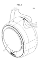
- FIG. 1 is a perspective view of an exemplary wall-mounted drum type washing machine in accordance with one or more embodiment(s) of the present invention.
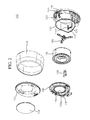
- FIG. 2 is an exploded perspective view of the exemplary wall-mounted drum type washing machine in accordance with embodiment(s) of the present invention.
- FIG. 3 is an exploded perspective view of an exemplary front panel mounting structure for a wall-mounted drum type washing machine in accordance with embodiment(s) of the present invention.
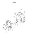
- FIG. 4 is an exploded perspective view of an exemplary gasket and heater mounting structure for a wall-mounted drum type washing machine in accordance with embodiment(s) of the present invention.
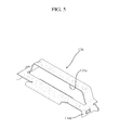
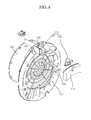
- FIG. 5 is a perspective view of an exemplary bracket for a wall-mounted drum type washing machine in accordance with embodiment(s) of the present invention.
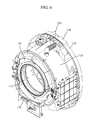
- FIG. 6 is a perspective view illustrating an exemplary tub, front panel, and gasket mounting structure for a wall-mounted drum type washing machine in accordance with embodiment(s) of the present invention.
- FIG. 7 is a rear perspective view of the exemplary tub for the exemplary wall-mounted drum type washing machine in accordance with embodiment(s) of the present invention.
- FIG. 8 is an exploded perspective view of an exemplary water supply device for a wall-mounted drum type washing machine in accordance with embodiment(s) of the present invention.
- FIG. 9 is a rear perspective view of an exemplary connection portion for a wall-mounted drum type washing machine in accordance with embodiment(s) of the present invention.
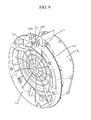
- FIG. 10 is a perspective view of the exemplary front panel of a wall-mounted drum type washing machine in accordance with embodiment(s) of the present invention.
- FIG. 11 is a cross-sectional view of the exemplary tub, front panel, and gasket mounting structure for the wall-mounted drum type washing machine in accordance with embodiment(s) of the present invention.
- FIG. 12 is a cross-sectional view of the exemplary wall-mounted drum type washing machine in accordance with embodiment(s) of the present invention.
- the exemplary wall-mounted drum type washing machine in accordance with embodiment(s) of the present invention includes a cabinet 110, a tub 130, a drum 156, a water supply device 150, and a drain device 30, 40, and 50.
- the tub 130 is in the cabinet 110 and is configured to contain water.
- the drum 156 is rotatable and is inside the tub 130.
- the water supply device 150 serves to supply wash water into the tub 130 through a top surface of the cabinet 110.
- the drain device 30, 40, and 50 serves to discharge the wash water in the tub 130 to the outside.
- wash water is supplied to the tub 130 by the water supply device 150.
- the water supply device 150 is at an upper or top surface of the cabinet 110. Therefore, the wash water is supplied to the tub 130 through the upper or top surface of the cabinet 110.
- the water supply device 150 is connected to the rear surface of the cabinet.
- the cabinet 110 since the water supply device 150 is in/on the upper or top surface of the cabinet 110, the cabinet 110 may be mounted or installed so that the rear surface thereof is closely attached to a wall surface W. Accordingly, the wall-mounted drum type washing machine may be easily implemented.
- the water supply device 150 includes a water supply pipe 152 between an upper or top surface of the cabinet 110 and the rear surface of the tub 130.
- the water supply pipe 152 may extend from the top or upper surface of the cabinet 110. Therefore, when a water supply hose is connected to the water supply pipe 152, wash water may be supplied into the interior of the cabinet 110 by the water supply pipe 152. The wash water supplied by the water supply pipe 152 is supplied into the tub 130 through the rear side of the tub 130.
- the wash water supplied by the water supply pipe 152 flows onto the outer wall of the drum 156 from the rear side of the drum 156, and then flows into the drum 156 through a plurality of holes in the wall of the drum 156.
- the wash water flowing onto the outer wall of the drum 156 is supplied into the drum 156 through the holes in the wall of the drum 156, the wash water may be uniformly supplied to the laundry in the drum 156, which makes it possible to increase wetting efficiency.
- the cabinet 110 includes a rear panel 120, a box unit 118, and a cover unit 112.
- the rear panel 120 is mounted on the wall surface W and is integral with the tub 130.
- the box unit 118 is detachably coupled to the rear panel 120 and configured to surround the tub 130.
- the cover unit 112 is installed in and/or on the box unit 118 and has a door 114 provided thereon.
- the rear panel 120 is coupled to the wall surface W using a coupling member 190, and is integral with the tub 130.
- the rear panel 120 is integral with the tub 130, a damper or damping spring is not required to support the tub 130, unlike the conventional wall-mounted washing machine. Therefore, the number of parts and the size of the wall-mounted drum type washing machine may be reduced.
- the rear panel 120 serves as a support member for supporting the tub 130 and as a mounting member for mounting the cabinet 110 on the wall surface W. Therefore, the structure of the cabinet 110 is simplified, and the support structure of the tub 130 is simplified.
- the rear panel 120 has a front side (i.e., away from the wall) having a circular shape, and the cylindrical tub 130 may be integral with the front surface of the rear panel 120.
- the front shape of the rear panel 120 may be replaced with another shape, instead of a circular shape.
- the tub 130 has a cylindrical or conical shape, of which the diameter may gradually increase toward the door 114. Accordingly, the wash water supplied into the tub 130 flows toward the front side of the tub 130 from the rear side of the tub 130.
- the box unit 118 has a cylindrical shape, of which front and rear surfaces are opened.
- the box unit 118 has a larger diameter than the tub 130, to enable the box unit 118 to surround the circumferential surface of the tub 130.
- the rear end portion or rear surface of the box unit 118 is detachably coupled to the rear panel 120 using one or more screws or the like. That is, the tub 130 is surrounded by the box unit 118 when the box unit 118 is coupled to the rear panel 120.
- the cover unit 112 is installed at the front opening of the box unit 118.
- the cover unit 112 has a circular panel shape and/or a circular plane shape, and includes an opening in the central portion thereof. The opening is opened and/or closed by the door 114 attached to the cover unit 112.
- the wall of the tub 130 is covered by a detachable front panel 136 having a housing hole 136a therein, and the box unit 118 is coupled to the rear panel 120 and surrounds the tub 130.
- the cover unit 112 is at the front side of the box unit 118 and covers the front panel 136.
- the front panel 136 is at least partially surrounded by the cover unit 112.
- the cover unit 112 is reliably fixed and elastically coupled to the box unit 118, and the box unit 118 is coupled to the rear panel 120 mounted on the wall surface W using a coupling member or the like. Therefore, it is possible to support the tub 130 while reducing vibrations of the front portion of the tub 130, without a damper or damping spring to support the front portion of the tub 130.
- the exterior shape of the wall-mounted drum type washing machine is not limited to a hexahedral shape, but may be changed to various shapes.
- a cabinet 110 forming a circular exterior shape of the wall-mounted drum type washing machine is taken as an example.
- the tub 130 is formed integrally with the rear panel 120 by insert injection molding or the like. Furthermore, the rear panel 120 is reliably mounted on the wall surface W using one or more coupling members 190. Since the tub 130 is integral with the rear panel 120, which is directly coupled and fixed to the wall surface W, a damper or damping spring for damping vibrations of the tub 130 may be omitted.
- drum 156 in accordance with embodiment(s) of the present invention is manufactured with a small capacity to house and wash only a small amount of laundry, vibrations generated by the rotation of the drum 156 may be sufficiently offset by the coupling force between the rear panel 120 and the wall W through the coupling member(s) 190.
- the rear panel 120 has a mounting groove 122 that forms a space between the wall surface W and the rear panel 120.
- the mounting groove 122 is concave toward the front side from the rear-side circumference of the rear panel 120.
- a driving unit 180 may be located in the space in the mounting groove 122 between the wall surface W and the rear surface of the rear panel 120. Therefore, since a separate space for the driving unit 180 within the cabinet 110 in front of the rear panel 120 is not absolutely necessary, the distance of the front of the wall-mounted drum type washing machine from the wall surface W may be reduced or minimized. As a result, it is possible to reduce the size of the wall-mounted drum type washing machine.
- the water supply pipe 152 protrudes upward from the top surface of the cabinet 110. Specifically, the water supply pipe 152 is in a connection portion 124 in a partitioned portion of the mounting groove 122. The water supply pipe 152 in or on an upper or top surface of the rear panel 120 does not interfere with the box unit 118.
- the water supply device 150 may be examined, replaced or repaired when the box unit 118 is in place on the rear panel 120.
- a water supply valve 154 is in the connection portion 124 and connected to the water supply pipe 152.
- a cover 128 is detachably mounted on or over the connection portion 124.
- the cover 128 is configured to cover the water supply pipe 152 and the water supply valve 154. Accordingly, when the cover 128 is separated or removed from the connection portion 124, the operation of examining, replacing or repairing the water supply pipe 152 or the water supply valve 154 may be immediately performed.
- a plurality of coupling holes 126 having a pillar or other suitable shape are on the top or upper surface of the rear panel 120.
- One or more of the coupling holes 126 may be configured to fix or attach the water supply valve 154 to the connection portion 124 using a screw or the like.
- the cover 128 is coupled to any one (e.g., 126a) of the coupling holes 126 using a screw or the like.
- the box unit 118 is reliably coupled to the rear panel 120 using any one (e.g., 126b) of the coupling holes 126 using a screw or the like.
- the cover 128 When the screw or the like in the coupling hole 126 is removed, the cover 128 may be separated or removed from the connection portion 124. Furthermore, the water supply valve 154 exposed to the outside by removing the cover 128 may be easily separated or removed from the water supply pipe 152.
- the water supply valve 154 When the water supply valve 154 is broken, the water supply valve 154 may be immediately replaced by removing the cover 128 from the connection portion 124 when the box unit 118 is in place on the rear panel 120.
- the rear panel 120 and the tub 130 may comprise a synthetic resin material. Furthermore, since the rear panel 120 and the tub 130 may be manufactured by insert injection molding, the tub 130 and the rear panel 120 may be simultaneously manufactured by one molding operation, and the tub 130 and the rear panel 120 are integrated by the molding process. Accordingly, it is possible to reduce the time and cost for manufacturing the tub 130 and the rear panel 120.
- the driving unit 180 is configured to provide power to the drum 156, and is at, in and/or on the rear side of the rear panel 120.
- the driving unit 180 includes a motor 182, a rotating shaft 184, and a support 186.
- the motor 182 is at the rear side of the rear panel 120, or specifically, in the mounting groove 122.
- the rotating shaft 184 transmits power from the motor 182, and extends through the real panel 120.
- the support 186 connects the rotating shaft 184 and the drum 156.
- the support 186 may have a tripod shape and be attached to the outer wall of the rear surface of the drum 156.
- the rotating shaft 184 is coupled or attached to the center of the support 186, and the power of the motor 182 is transmitted to the drum 156 through the rotating shaft 184 and the support 186.
- the tub 130 includes a receiving groove 132 having a heater 139 thereon.
- a slidable bracket 134 configured to support the heater 139 is coupled to or mounted on the receiving groove 132.
- the receiving groove 132 is formed on a bottom or lower part of the tub 130 direction.
- the receiving groove 132 includes a pair of rails 132a therein such that the bracket 134 may be slidably inserted into the rails 132a.
- the bracket 134 includes a pair of protrusions 134b and an insertion hole 134a.
- the protrusions 134b slide along the rails 132a.
- the insertion hole 134a is between the protrusions 134b, and one end portion of the heater 139 is inserted into the insertion hole 134a.
- the front panel 136 is at the front of the tub 130, and has a connection hole 138 therein to support the heater 139. Therefore, the heater 139 may be inserted through the connection hole portion 138 when the front panel 136 is on or over the tub 130, and one end portion of the heater 139 is supported by the insertion hole 134a, while another end portion of the heater 139 is supported by the connection hole portion 138.
- an operator may immediately remove the heater 139 through the connection hole portion 138, without removing the front panel 136 from the tub 130.
- the cover unit 112 having the door 114 thereon may be on the box unit 118, and the gasket 116 is in or around the housing hole 136a of the front panel 136 facing the door 114.
- FIG. 13 is a perspective view of an exemplary drain device mounting structure for a wall-mounted drum type washing machine in accordance with embodiment(s) of the present invention.
- FIG. 14 is an exploded perspective view of the exemplary drain device mounting structure in accordance with embodiment(s) of the present invention.
- FIG. 15 is an exploded perspective view of an exemplary drain device for a wall-mounted drum type washing machine in accordance with embodiment(s) of the present invention.
- FIG. 16 is a side cross-sectional view illustrating an exemplary assembled drain device in accordance with embodiment(s) of the present invention.
- FIG. 17 is a plan cross-sectional view of the exemplary drain device in accordance with embodiment(s) of the present invention.
- the drain device 30, 40, and 50 at the bottom of the tub 130 is configured to discharge wash water collected at the bottom of the tub 130 and/or the drum 156.
- the drain device 30, 40, and 50 in accordance with embodiment(s) of the present invention includes a first drain pipe 30, a second drain pipe 40, and a siphon drain unit 50.
- the first drain pipe 30 is at the bottom of the tub 130.
- the wash water supplied to the drum 156 is discharged from the tub 130 and/or the cabinet 110 through the first drain pipe 30 after the washing operation is performed or completed.
- the second drain pipe 40 is under the first drain pipe 30, and has a larger diameter than the first drain pipe 30.
- the second drain pipe 40 is connected to the first drain pipe 30 through the siphon drain unit 50.
- the second drain pipe 40 includes a drain valve 42 to control the amount of wash water discharged from the washing machine.
- the drain valve 42 may include a solenoid valve.
- the first and second drain pipes 30 and 40 are arranged in such a manner that the central lines or axes thereof vertically coincide with each other.
- the siphon drain unit 50 is between the first and second drain pipes 30 and 40.
- the siphon drain unit 50 applies siphon pressure to the first drain pipe 30 using wash water in the second drain pipe 40, thereby promoting the discharge of the wash water.
- the siphon drain unit 50 includes a body 52, a drain induction member 70, and a siphon induction pipe 74.
- the body 52 includes an inlet 55 connected to the first drain pipe 30 and an outlet 61 connected to the second drain pipe 40, and has an internal space to store wash water.
- the body 52 is divided into a first body 54, a second body 60, and one or more fixing members 66.
- the first body 54 includes the inlet 55 and a first flange 56 on the lower circumference thereof.
- the second body 60 includes the outlet 61 and a second flange 62 contacting with the first flange 56.
- the fixing member(s) 66 couples the first and second flanges 56 and 62.
- an O-ring 68 for sealing may be provided on corresponding inner surfaces of the first and second flanges 56 and 62.
- the O-ring 68 may have a circular or polygonal cross-section. In this embodiment of the present invention, the O-ring 68 has a circular cross-section.
- the O-ring 68 is in a first receiving groove 58 in the first flange 56 and a second receiving groove 64 in the second flange 62.
- the first and second receiving grooves 58 and 64 face each other.
- the fixing member(s) 66 include a bolt inserted into holes in the first and second flanges 56 and 62, respectively, and a nut coupled or fastened to the bolt. If necessary, another fixing member such as a screw may be used.
- the drain induction member 70 is in the body 52, and may have a cap shape.
- the drain induction member 70 has a space therein.
- the drain induction member 70 is supported by a plurality of support members 72 between an inner surface of the body 52 and an outer surface of the drain induction member 70.
- the lower circumferential surface of the drain induction member 70 is a predetermined distance from the bottom surface of the second body 60. This structure may be implemented by connecting the outer surface of the drain induction member 70 and the inner surface of the second body 52 through the support members 72.
- the siphon induction pipe 74 is fixed to the body 52 such that wash water rises and is then discharged through the outlet 61.
- the inner wall of the drain induction member 70 is separate from and/or surrounding the outer wall of the siphon induction pipe 74, and the wash water rises through a flow path 76 in the space between the inner wall of the drain induction member 70 and the outer wall of the siphon induction pipe 74.
- the siphon induction pipe 74 extends upward from the bottom surface of the body 52 and is connected to the outlet 61.
- the siphon induction pipe 74 may have an inner diameter equal to that of the outlet 61.
- the outlet 61 may also have an inner diameter equal to that of the second drain pipe 40.
- the drain induction member 70 surrounds the upper portion of the siphon induction pipe 74, and the gap between the inner wall of the drain induction member 70 and the outer wall of the siphon induction member 74 serves as the flow path 76.
- wash water introduced into the body 52 through the first drain pipe 30 strikes the drain induction member 70 and then moves toward the outer edge of the drain induction member 70 (that is, the inner wall of the body 52). Then, the wash water drops toward the bottom of the body 52, rises along the flow path 76 between the drain induction member 70 and the siphon induction pipe 74, and then flows through the outlet 61 via the siphon induction pipe 74.
- siphon pressure can be applied to the first drain pipe 30.
- FIG. 18 is a diagram illustrating an example in which the wall-mounted drum type washing machine in accordance with embodiment(s) of the present invention is installed on a wall surface.
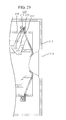
- FIG. 19 is a diagram illustrating a modified example in which the wall-mounted drum type washing machine in accordance with embodiment(s) of the present invention is installed on a wall surface.
- the rear panel 120 is installed on the wall surface W using a plurality of coupling members 190. Specifically, when the rear panel 120 is attached to the wall surface W, a planar surface at the edge of the rear surface thereof is in contact with the wall surface W.
- the coupling member 190 is coupled, attached or fixed to the wall surface W through a hole 121 in the rear panel 120.
- the rear panel 120 may be reliably fixed to the wall surface W. Therefore, even when an external force is applied to the wall-mounted drum type washing machine, it is possible to prevent the wall-mounted drum type washing machine from falling down or falling off the wall. Furthermore, since a separate bracket for fixing the wall-mounted drum type washing machine to the wall is not needed, the number of parts and weight of the wall-mounted drum type washing machine may be reduced.
- an additional buffer member 192 may be between the rear panel 120 and the wall surface W. Since the rear panel 120 and the wall surface W are not in direct contact with each other because of the buffer member 192, it is possible to reduce, minimize or prevent vibrations of the drum 156 from being transmitted to the wall surface W through the rear panel 120 during the operation of the wall-mounted drum type washing machine. Accordingly, it is possible to reduce adverse effects of vibrations and noise occurring during the washing operation of the wall-mounted drum type washing machine.
- wash water is supplied into the tub 130 through the water supply pipe 152 by the operation of the water supply valve 154.
- the wash water supplied along the water supply pipe 152 on the top or upper surface of the cabinet 110 is supplied to the tub 130 through the rear panel 120.
- the wash water is supplied to the tub 130 through the concave mounting groove 122 in the rear panel 120 (refer to FIGS. 11 and 12 ).
- the wash water flows the water supply pipe 152 and passes through the rear panel 120, the wash water flows to the rear side of the tub 130. Then, the wash water is supplied to the front side of the tub 130 from the rear side of the tub 130.
- the wash water supplied from the rear surface of the tub 130 is supplied to both of the rear surface and the circumferential surface of the drum 156, the wash water may wash foreign matters remaining on the inner wall of the tub 130 and the outer wall of the drum 156.
- the body 52 and the second drain pipe 40 may already store some wash water before the drain valve 42 is opened.
- a negative pressure is generated to pull the wash water in the body 52 through the outlet 61, the siphon induction pipe 74, and the flow path 76.
- siphon pressure is applied to the wash water flowing to the first drain pipe 30 having a smaller diameter than the diameter of the second drain pipe 40, thereby increasing the drain pressure. Accordingly, the discharge of detergent bubbles and wash water remaining in the drum 156 or the tub 130 may be promoted.
- the drain device 30, 40, and 50 in accordance with embodiment(s) of the present invention promotes the process of draining wash water using the siphon principle, unlike the conventional drain device using the free fall principle. Therefore, it is possible to not only drain the wash water more smoothly, but also reduce the drain time.
- FIG. 20 is an exploded perspective view of an exemplary gasket mounting structure for a wall-mounted drum type washing machine in accordance with one or more other embodiments of the present invention.
- FIG. 21 is a cross-sectional view of the exemplary gasket mounting structure in accordance with embodiment(s) of the present invention.
- FIG. 22 is a cross-sectional view illustrating an exemplary protrusion gasket added to the exemplary gasket of FIG. 21 in accordance with embodiment(s) of the present invention.
- FIG. 23 is a cross-sectional view illustrating an exemplary ring spring is added to an exemplary gasket for a wall-mounted drum type washing machine in accordance with embodiment(s) of the present invention.
- a gasket 220 in accordance with embodiment(s) of the present invention has one end portion coupled to a tub 230 and another end portion in contact with a door 314 on a cover unit 312.
- the gasket 220 comprises an elastic material such as rubber, and has a wrinkled surface. Therefore, the length of the gasket 220 may vary when vibration occurs in the tub 230.
- the tub 230 includes a plurality of mounting holes 213 in the front end portion thereof and a plurality of lock portions 214 that protrude or extend from the outer circumference of the tub 230.
- the gasket 220 is locked and fixed to the lock portions 214 and extends through the mounting holes 213.
- Each of the lock portions 214 may include a coupling protrusion 215 and a lock protrusion 216.
- the coupling protrusion 215 extends or protrudes outward from the outer surface of the tub 230.
- the coupling protrusion 215 is adjacent to the mounting hole 213.
- the plurality of mounting holes 213 are arranged along the circumferential surface of the tub 230.
- the lock protrusion 216 extends from the end of the coupling protrusion 215 in the opposite direction of the mounting hole 213.
- the lock portion 214 may include only the coupling protrusion 215, without the lock protrusion 216.
- the gasket 220 in accordance with embodiment(s) of the present invention includes a bent, hooked or curved body 221, a passing body 222, and a coupling body 223.
- the hooked body 221 has a bent, curved and/or hooked shape configured to lock to or mate with the lock portion 214.
- the hooked body 221 is bent or curved to fit or mate closely with the coupling protrusion 215, and has an end locked and fixed to the lock protrusion 216.
- the passing body 222 is connected to the hooked body 221, and passes through the mounting hole 213.
- the passing body 222 may be integral with the hooked body 221.
- the passing body 222 may additionally include a separate seal to prevent leakage of wash water through the mounting hole 213.
- the coupling body 223 is connected to the passing body 222.
- the coupling body 223 may be integral with the passing body 222.
- the coupling body 223 generally contacts the door 314 and is configured to prevent wash water from leaking through a gap between the tub 230 and the door 314.
- the gasket 220 in accordance with embodiment(s) of the present invention may further include a protrusion body 224.
- the protrusion body 224 is coupled, fixed or attached to the hooked body 221, and protrudes or extends in a side direction so as to lock to the tub 230.
- the protrusion body 224 may be bonded or adhered to the hooked body 221 or integral with the hooked body 221.
- the protrusion body 224 is configured to contact the outer surface of the tub 230.
- the end portion of the hooked body 221 inserted into the lock portion 214 may have a U shape, and the gasket 220 may further include a ring spring 225.
- the ring spring 225 is inserted into an end portion of the hooked body 221, and fixes, secures and/or closely attaches the hooked body 221 to the circumferential surface of the tub 230 and/or to the lock portion 214.
- the ring spring 225 has a diameter corresponding to or slightly greater than or less than, the tub 230, is configured to surround the tub 230, and expands by an external force.
- the end portion of the hooked body 221 is bent or curved to fit or mate closely with the lock protrusion 216, the coupling protrusion 215, and the tub 230, and may form a space into which the ring spring 225 can be inserted.
- the shape of the cabinet, the connection structure of the tub, and the mounting structure of the driving unit may be improved to reduce the size of and the number of parts in the wall-mounted drum type washing machine. Accordingly, it is possible to provide a wall-mounted drum type washing machine which may be mounted in various places and perform a hot water washing operation.
- the wall-mounted drum type washing machine has been taken as an example for description. However, this is only an example, and the wall-mounted drum type washing machine in accordance with embodiment(s) of the present invention may be applied to other products.
Landscapes
- Engineering & Computer Science (AREA)
- Textile Engineering (AREA)
- Main Body Construction Of Washing Machines And Laundry Dryers (AREA)
- Detail Structures Of Washing Machines And Dryers (AREA)
Applications Claiming Priority (3)
| Application Number | Priority Date | Filing Date | Title |
|---|---|---|---|
| KR1020110131335A KR101861338B1 (ko) | 2011-12-08 | 2011-12-08 | 벽걸이형 미니 드럼세탁기 |
| KR1020110146687A KR20130077994A (ko) | 2011-12-30 | 2011-12-30 | 벽걸이형 미니 드럼세탁기 |
| PCT/KR2012/010513 WO2013085292A1 (ko) | 2011-12-08 | 2012-12-06 | 벽걸이형 드럼세탁기 |
Publications (3)
| Publication Number | Publication Date |
|---|---|
| EP2728060A1 true EP2728060A1 (de) | 2014-05-07 |
| EP2728060A4 EP2728060A4 (de) | 2015-02-25 |
| EP2728060B1 EP2728060B1 (de) | 2016-08-17 |
Family
ID=48574579
Family Applications (1)
| Application Number | Title | Priority Date | Filing Date |
|---|---|---|---|
| EP12855802.0A Not-in-force EP2728060B1 (de) | 2011-12-08 | 2012-12-06 | Wandmontierte trommelwaschmaschine |
Country Status (5)
| Country | Link |
|---|---|
| US (1) | US9708743B2 (de) |
| EP (1) | EP2728060B1 (de) |
| CN (1) | CN103958761B (de) |
| ES (1) | ES2592539T3 (de) |
| WO (1) | WO2013085292A1 (de) |
Families Citing this family (7)
| Publication number | Priority date | Publication date | Assignee | Title |
|---|---|---|---|---|
| CN107419475A (zh) * | 2016-05-24 | 2017-12-01 | 王军 | 一种壁挂式滚筒洗衣机 |
| KR20180136087A (ko) * | 2017-06-14 | 2018-12-24 | 주식회사 대우전자 | 벽걸이형 세탁기 및 그의 도어 개스킷 |
| KR20180136088A (ko) * | 2017-06-14 | 2018-12-24 | 주식회사 대우전자 | 벽걸이형 세탁기 및 그의 도어 개스킷 |
| KR20180136091A (ko) * | 2017-06-14 | 2018-12-24 | 주식회사 대우전자 | 벽걸이형 세탁기 및 그의 리어 패널 |
| KR20180136687A (ko) * | 2017-06-15 | 2018-12-26 | 주식회사 대우전자 | 벽걸이형 드럼 세탁기 |
| CN109576949A (zh) * | 2017-09-28 | 2019-04-05 | 青岛海尔洗衣机有限公司 | 一种壁挂式洗衣机 |
| CN112111936A (zh) * | 2020-10-22 | 2020-12-22 | 上海优未科技有限公司 | 一种壁挂式迷你洗衣机 |
Citations (2)
| Publication number | Priority date | Publication date | Assignee | Title |
|---|---|---|---|---|
| US5421175A (en) * | 1994-02-10 | 1995-06-06 | Niu; Chi-Chou | Stocking washing machine |
| EP2317001A1 (de) * | 2009-10-29 | 2011-05-04 | Electrolux Home Products Corporation N.V. | Haushaltsgerät mit Wandbefestigung |
Family Cites Families (9)
| Publication number | Priority date | Publication date | Assignee | Title |
|---|---|---|---|---|
| US2292787A (en) * | 1940-06-21 | 1942-08-11 | American Laundry Mach Co | Washing machine |
| DE1801873A1 (de) * | 1967-11-17 | 1969-08-07 | Maytag Co | Einrichtung zum Trocknen von Waeschestuecken od.dgl. |
| US5868011A (en) * | 1997-04-04 | 1999-02-09 | General Electric Company | Water traps for washing machines |
| CN2419235Y (zh) * | 1999-12-13 | 2001-02-14 | 山东小鸭电器股份有限公司 | 滚筒洗衣机驱动装置 |
| KR200305578Y1 (ko) * | 2002-11-21 | 2003-02-26 | 김성곤 | 벽걸이 소형 드럼 세탁기 |
| KR100826174B1 (ko) * | 2004-12-30 | 2008-04-30 | 엘지전자 주식회사 | 벽걸이용 세탁 장치 |
| KR20060125298A (ko) * | 2005-06-02 | 2006-12-06 | 추성엽 | 드럼 세탁기 |
| JP4368898B2 (ja) * | 2007-04-02 | 2009-11-18 | 日立アプライアンス株式会社 | ドラム式洗濯機 |
| EP2317002B1 (de) | 2009-10-29 | 2012-05-16 | Electrolux Home Products Corporation N.V. | Haushaltsgerät zur Wandanbringung |
-
2012
- 2012-12-06 WO PCT/KR2012/010513 patent/WO2013085292A1/ko active Application Filing
- 2012-12-06 EP EP12855802.0A patent/EP2728060B1/de not_active Not-in-force
- 2012-12-06 ES ES12855802.0T patent/ES2592539T3/es active Active
- 2012-12-06 CN CN201280021246.6A patent/CN103958761B/zh not_active Expired - Fee Related
- 2012-12-06 US US14/119,437 patent/US9708743B2/en not_active Expired - Fee Related
Patent Citations (2)
| Publication number | Priority date | Publication date | Assignee | Title |
|---|---|---|---|---|
| US5421175A (en) * | 1994-02-10 | 1995-06-06 | Niu; Chi-Chou | Stocking washing machine |
| EP2317001A1 (de) * | 2009-10-29 | 2011-05-04 | Electrolux Home Products Corporation N.V. | Haushaltsgerät mit Wandbefestigung |
Non-Patent Citations (1)
| Title |
|---|
| See also references of WO2013085292A1 * |
Also Published As
| Publication number | Publication date |
|---|---|
| CN103958761A (zh) | 2014-07-30 |
| WO2013085292A1 (ko) | 2013-06-13 |
| EP2728060B1 (de) | 2016-08-17 |
| US9708743B2 (en) | 2017-07-18 |
| CN103958761B (zh) | 2017-04-05 |
| EP2728060A4 (de) | 2015-02-25 |
| US20140102150A1 (en) | 2014-04-17 |
| ES2592539T3 (es) | 2016-11-30 |
Similar Documents
| Publication | Publication Date | Title |
|---|---|---|
| EP2728060A1 (de) | Wandmontierte trommelwaschmaschine | |
| US10472758B2 (en) | Wall-mounted drum-type washing machine | |
| US10428452B2 (en) | Wall-mounted drum type washing machine | |
| US10260190B2 (en) | Wall-mounted drum type washing machine | |
| US10465326B2 (en) | Wall-mounted drum type washing machine | |
| US10301758B2 (en) | Wall-mounted drum-type washing machine | |
| US9783924B2 (en) | Wall-mounted drum-type washing machine | |
| US10174451B2 (en) | Wall-mounted drum-type washing machine | |
| KR101864844B1 (ko) | 벽걸이형 미니 드럼세탁기 | |
| KR101861338B1 (ko) | 벽걸이형 미니 드럼세탁기 | |
| KR101864832B1 (ko) | 벽걸이형 미니 드럼세탁기 | |
| KR101861336B1 (ko) | 벽걸이형 미니 드럼세탁기 | |
| KR101861339B1 (ko) | 벽걸이형 미니 드럼세탁기 |
Legal Events
| Date | Code | Title | Description |
|---|---|---|---|
| PUAI | Public reference made under article 153(3) epc to a published international application that has entered the european phase |
Free format text: ORIGINAL CODE: 0009012 |
|
| 17P | Request for examination filed |
Effective date: 20131112 |
|
| AK | Designated contracting states |
Kind code of ref document: A1 Designated state(s): AL AT BE BG CH CY CZ DE DK EE ES FI FR GB GR HR HU IE IS IT LI LT LU LV MC MK MT NL NO PL PT RO RS SE SI SK SM TR |
|
| RAP1 | Party data changed (applicant data changed or rights of an application transferred) |
Owner name: DONGBU DAEWOO ELECTRONICS CORPORATION |
|
| A4 | Supplementary search report drawn up and despatched |
Effective date: 20150123 |
|
| RIC1 | Information provided on ipc code assigned before grant |
Ipc: D06F 39/08 20060101ALI20150119BHEP Ipc: D06F 39/12 20060101AFI20150119BHEP Ipc: D06F 37/20 20060101ALI20150119BHEP Ipc: D06F 39/14 20060101ALI20150119BHEP |
|
| DAX | Request for extension of the european patent (deleted) | ||
| GRAP | Despatch of communication of intention to grant a patent |
Free format text: ORIGINAL CODE: EPIDOSNIGR1 |
|
| INTG | Intention to grant announced |
Effective date: 20160309 |
|
| GRAS | Grant fee paid |
Free format text: ORIGINAL CODE: EPIDOSNIGR3 |
|
| GRAA | (expected) grant |
Free format text: ORIGINAL CODE: 0009210 |
|
| AK | Designated contracting states |
Kind code of ref document: B1 Designated state(s): AL AT BE BG CH CY CZ DE DK EE ES FI FR GB GR HR HU IE IS IT LI LT LU LV MC MK MT NL NO PL PT RO RS SE SI SK SM TR |
|
| REG | Reference to a national code |
Ref country code: GB Ref legal event code: FG4D |
|
| REG | Reference to a national code |
Ref country code: CH Ref legal event code: EP |
|
| REG | Reference to a national code |
Ref country code: IE Ref legal event code: FG4D |
|
| REG | Reference to a national code |
Ref country code: AT Ref legal event code: REF Ref document number: 821210 Country of ref document: AT Kind code of ref document: T Effective date: 20160915 |
|
| REG | Reference to a national code |
Ref country code: DE Ref legal event code: R096 Ref document number: 602012022057 Country of ref document: DE |
|
| REG | Reference to a national code |
Ref country code: NL Ref legal event code: FP |
|
| REG | Reference to a national code |
Ref country code: ES Ref legal event code: FG2A Ref document number: 2592539 Country of ref document: ES Kind code of ref document: T3 Effective date: 20161130 |
|
| REG | Reference to a national code |
Ref country code: FR Ref legal event code: PLFP Year of fee payment: 5 |
|
| REG | Reference to a national code |
Ref country code: LT Ref legal event code: MG4D |
|
| REG | Reference to a national code |
Ref country code: AT Ref legal event code: MK05 Ref document number: 821210 Country of ref document: AT Kind code of ref document: T Effective date: 20160817 |
|
| PG25 | Lapsed in a contracting state [announced via postgrant information from national office to epo] |
Ref country code: FI Free format text: LAPSE BECAUSE OF FAILURE TO SUBMIT A TRANSLATION OF THE DESCRIPTION OR TO PAY THE FEE WITHIN THE PRESCRIBED TIME-LIMIT Effective date: 20160817 Ref country code: RS Free format text: LAPSE BECAUSE OF FAILURE TO SUBMIT A TRANSLATION OF THE DESCRIPTION OR TO PAY THE FEE WITHIN THE PRESCRIBED TIME-LIMIT Effective date: 20160817 Ref country code: HR Free format text: LAPSE BECAUSE OF FAILURE TO SUBMIT A TRANSLATION OF THE DESCRIPTION OR TO PAY THE FEE WITHIN THE PRESCRIBED TIME-LIMIT Effective date: 20160817 Ref country code: LT Free format text: LAPSE BECAUSE OF FAILURE TO SUBMIT A TRANSLATION OF THE DESCRIPTION OR TO PAY THE FEE WITHIN THE PRESCRIBED TIME-LIMIT Effective date: 20160817 Ref country code: NO Free format text: LAPSE BECAUSE OF FAILURE TO SUBMIT A TRANSLATION OF THE DESCRIPTION OR TO PAY THE FEE WITHIN THE PRESCRIBED TIME-LIMIT Effective date: 20161117 |
|
| PG25 | Lapsed in a contracting state [announced via postgrant information from national office to epo] |
Ref country code: SE Free format text: LAPSE BECAUSE OF FAILURE TO SUBMIT A TRANSLATION OF THE DESCRIPTION OR TO PAY THE FEE WITHIN THE PRESCRIBED TIME-LIMIT Effective date: 20160817 Ref country code: GR Free format text: LAPSE BECAUSE OF FAILURE TO SUBMIT A TRANSLATION OF THE DESCRIPTION OR TO PAY THE FEE WITHIN THE PRESCRIBED TIME-LIMIT Effective date: 20161118 Ref country code: LV Free format text: LAPSE BECAUSE OF FAILURE TO SUBMIT A TRANSLATION OF THE DESCRIPTION OR TO PAY THE FEE WITHIN THE PRESCRIBED TIME-LIMIT Effective date: 20160817 Ref country code: PT Free format text: LAPSE BECAUSE OF FAILURE TO SUBMIT A TRANSLATION OF THE DESCRIPTION OR TO PAY THE FEE WITHIN THE PRESCRIBED TIME-LIMIT Effective date: 20161219 Ref country code: PL Free format text: LAPSE BECAUSE OF FAILURE TO SUBMIT A TRANSLATION OF THE DESCRIPTION OR TO PAY THE FEE WITHIN THE PRESCRIBED TIME-LIMIT Effective date: 20160817 Ref country code: AT Free format text: LAPSE BECAUSE OF FAILURE TO SUBMIT A TRANSLATION OF THE DESCRIPTION OR TO PAY THE FEE WITHIN THE PRESCRIBED TIME-LIMIT Effective date: 20160817 |
|
| PG25 | Lapsed in a contracting state [announced via postgrant information from national office to epo] |
Ref country code: RO Free format text: LAPSE BECAUSE OF FAILURE TO SUBMIT A TRANSLATION OF THE DESCRIPTION OR TO PAY THE FEE WITHIN THE PRESCRIBED TIME-LIMIT Effective date: 20160817 Ref country code: EE Free format text: LAPSE BECAUSE OF FAILURE TO SUBMIT A TRANSLATION OF THE DESCRIPTION OR TO PAY THE FEE WITHIN THE PRESCRIBED TIME-LIMIT Effective date: 20160817 |
|
| REG | Reference to a national code |
Ref country code: DE Ref legal event code: R097 Ref document number: 602012022057 Country of ref document: DE |
|
| PG25 | Lapsed in a contracting state [announced via postgrant information from national office to epo] |
Ref country code: DK Free format text: LAPSE BECAUSE OF FAILURE TO SUBMIT A TRANSLATION OF THE DESCRIPTION OR TO PAY THE FEE WITHIN THE PRESCRIBED TIME-LIMIT Effective date: 20160817 Ref country code: BG Free format text: LAPSE BECAUSE OF FAILURE TO SUBMIT A TRANSLATION OF THE DESCRIPTION OR TO PAY THE FEE WITHIN THE PRESCRIBED TIME-LIMIT Effective date: 20161117 Ref country code: CZ Free format text: LAPSE BECAUSE OF FAILURE TO SUBMIT A TRANSLATION OF THE DESCRIPTION OR TO PAY THE FEE WITHIN THE PRESCRIBED TIME-LIMIT Effective date: 20160817 Ref country code: SK Free format text: LAPSE BECAUSE OF FAILURE TO SUBMIT A TRANSLATION OF THE DESCRIPTION OR TO PAY THE FEE WITHIN THE PRESCRIBED TIME-LIMIT Effective date: 20160817 Ref country code: SM Free format text: LAPSE BECAUSE OF FAILURE TO SUBMIT A TRANSLATION OF THE DESCRIPTION OR TO PAY THE FEE WITHIN THE PRESCRIBED TIME-LIMIT Effective date: 20160817 Ref country code: BE Free format text: LAPSE BECAUSE OF FAILURE TO SUBMIT A TRANSLATION OF THE DESCRIPTION OR TO PAY THE FEE WITHIN THE PRESCRIBED TIME-LIMIT Effective date: 20160817 |
|
| PLBE | No opposition filed within time limit |
Free format text: ORIGINAL CODE: 0009261 |
|
| STAA | Information on the status of an ep patent application or granted ep patent |
Free format text: STATUS: NO OPPOSITION FILED WITHIN TIME LIMIT |
|
| 26N | No opposition filed |
Effective date: 20170518 |
|
| REG | Reference to a national code |
Ref country code: CH Ref legal event code: PL |
|
| PG25 | Lapsed in a contracting state [announced via postgrant information from national office to epo] |
Ref country code: SI Free format text: LAPSE BECAUSE OF FAILURE TO SUBMIT A TRANSLATION OF THE DESCRIPTION OR TO PAY THE FEE WITHIN THE PRESCRIBED TIME-LIMIT Effective date: 20160817 |
|
| PG25 | Lapsed in a contracting state [announced via postgrant information from national office to epo] |
Ref country code: MC Free format text: LAPSE BECAUSE OF FAILURE TO SUBMIT A TRANSLATION OF THE DESCRIPTION OR TO PAY THE FEE WITHIN THE PRESCRIBED TIME-LIMIT Effective date: 20160817 |
|
| REG | Reference to a national code |
Ref country code: IE Ref legal event code: MM4A |
|
| PG25 | Lapsed in a contracting state [announced via postgrant information from national office to epo] |
Ref country code: LI Free format text: LAPSE BECAUSE OF NON-PAYMENT OF DUE FEES Effective date: 20161231 Ref country code: CH Free format text: LAPSE BECAUSE OF NON-PAYMENT OF DUE FEES Effective date: 20161231 Ref country code: LU Free format text: LAPSE BECAUSE OF NON-PAYMENT OF DUE FEES Effective date: 20161206 |
|
| REG | Reference to a national code |
Ref country code: FR Ref legal event code: PLFP Year of fee payment: 6 |
|
| PG25 | Lapsed in a contracting state [announced via postgrant information from national office to epo] |
Ref country code: IE Free format text: LAPSE BECAUSE OF NON-PAYMENT OF DUE FEES Effective date: 20161206 |
|
| PG25 | Lapsed in a contracting state [announced via postgrant information from national office to epo] |
Ref country code: CY Free format text: LAPSE BECAUSE OF FAILURE TO SUBMIT A TRANSLATION OF THE DESCRIPTION OR TO PAY THE FEE WITHIN THE PRESCRIBED TIME-LIMIT Effective date: 20160817 Ref country code: HU Free format text: LAPSE BECAUSE OF FAILURE TO SUBMIT A TRANSLATION OF THE DESCRIPTION OR TO PAY THE FEE WITHIN THE PRESCRIBED TIME-LIMIT; INVALID AB INITIO Effective date: 20121206 |
|
| PG25 | Lapsed in a contracting state [announced via postgrant information from national office to epo] |
Ref country code: IS Free format text: LAPSE BECAUSE OF FAILURE TO SUBMIT A TRANSLATION OF THE DESCRIPTION OR TO PAY THE FEE WITHIN THE PRESCRIBED TIME-LIMIT Effective date: 20160817 Ref country code: MK Free format text: LAPSE BECAUSE OF FAILURE TO SUBMIT A TRANSLATION OF THE DESCRIPTION OR TO PAY THE FEE WITHIN THE PRESCRIBED TIME-LIMIT Effective date: 20160817 |
|
| PG25 | Lapsed in a contracting state [announced via postgrant information from national office to epo] |
Ref country code: MT Free format text: LAPSE BECAUSE OF NON-PAYMENT OF DUE FEES Effective date: 20161206 |
|
| PG25 | Lapsed in a contracting state [announced via postgrant information from national office to epo] |
Ref country code: TR Free format text: LAPSE BECAUSE OF FAILURE TO SUBMIT A TRANSLATION OF THE DESCRIPTION OR TO PAY THE FEE WITHIN THE PRESCRIBED TIME-LIMIT Effective date: 20160817 Ref country code: AL Free format text: LAPSE BECAUSE OF FAILURE TO SUBMIT A TRANSLATION OF THE DESCRIPTION OR TO PAY THE FEE WITHIN THE PRESCRIBED TIME-LIMIT Effective date: 20160817 |
|
| PGFP | Annual fee paid to national office [announced via postgrant information from national office to epo] |
Ref country code: DE Payment date: 20211130 Year of fee payment: 10 Ref country code: FR Payment date: 20211217 Year of fee payment: 10 Ref country code: GB Payment date: 20211206 Year of fee payment: 10 |
|
| PGFP | Annual fee paid to national office [announced via postgrant information from national office to epo] |
Ref country code: IT Payment date: 20211213 Year of fee payment: 10 |
|
| PGFP | Annual fee paid to national office [announced via postgrant information from national office to epo] |
Ref country code: NL Payment date: 20211216 Year of fee payment: 10 |
|
| PGFP | Annual fee paid to national office [announced via postgrant information from national office to epo] |
Ref country code: ES Payment date: 20220203 Year of fee payment: 10 |
|
| REG | Reference to a national code |
Ref country code: DE Ref legal event code: R119 Ref document number: 602012022057 Country of ref document: DE |
|
| REG | Reference to a national code |
Ref country code: NL Ref legal event code: MM Effective date: 20230101 |
|
| GBPC | Gb: european patent ceased through non-payment of renewal fee |
Effective date: 20221206 |
|
| PG25 | Lapsed in a contracting state [announced via postgrant information from national office to epo] |
Ref country code: NL Free format text: LAPSE BECAUSE OF NON-PAYMENT OF DUE FEES Effective date: 20230101 |
|
| PG25 | Lapsed in a contracting state [announced via postgrant information from national office to epo] |
Ref country code: GB Free format text: LAPSE BECAUSE OF NON-PAYMENT OF DUE FEES Effective date: 20221206 Ref country code: DE Free format text: LAPSE BECAUSE OF NON-PAYMENT OF DUE FEES Effective date: 20230701 |
|
| PG25 | Lapsed in a contracting state [announced via postgrant information from national office to epo] |
Ref country code: FR Free format text: LAPSE BECAUSE OF NON-PAYMENT OF DUE FEES Effective date: 20221231 |
|
| REG | Reference to a national code |
Ref country code: ES Ref legal event code: FD2A Effective date: 20240126 |
|
| PG25 | Lapsed in a contracting state [announced via postgrant information from national office to epo] |
Ref country code: IT Free format text: LAPSE BECAUSE OF NON-PAYMENT OF DUE FEES Effective date: 20221206 |
|
| PG25 | Lapsed in a contracting state [announced via postgrant information from national office to epo] |
Ref country code: ES Free format text: LAPSE BECAUSE OF NON-PAYMENT OF DUE FEES Effective date: 20221207 |
|
| PG25 | Lapsed in a contracting state [announced via postgrant information from national office to epo] |
Ref country code: ES Free format text: LAPSE BECAUSE OF NON-PAYMENT OF DUE FEES Effective date: 20221207 |