EP2727818A1 - Ship maneuvering device - Google Patents
Ship maneuvering device Download PDFInfo
- Publication number
- EP2727818A1 EP2727818A1 EP20120804380 EP12804380A EP2727818A1 EP 2727818 A1 EP2727818 A1 EP 2727818A1 EP 20120804380 EP20120804380 EP 20120804380 EP 12804380 A EP12804380 A EP 12804380A EP 2727818 A1 EP2727818 A1 EP 2727818A1
- Authority
- EP
- European Patent Office
- Prior art keywords
- outdrive
- angle
- rotation speed
- pair
- rotation
- Prior art date
- Legal status (The legal status is an assumption and is not a legal conclusion. Google has not performed a legal analysis and makes no representation as to the accuracy of the status listed.)
- Granted
Links
- 239000013598 vector Substances 0.000 claims abstract description 92
- 239000000203 mixture Substances 0.000 claims description 51
- 238000001514 detection method Methods 0.000 claims description 41
- 230000009467 reduction Effects 0.000 claims description 20
- 230000035945 sensitivity Effects 0.000 abstract description 2
- MEFOUWRMVYJCQC-UHFFFAOYSA-N rimsulfuron Chemical compound CCS(=O)(=O)C1=CC=CN=C1S(=O)(=O)NC(=O)NC1=NC(OC)=CC(OC)=N1 MEFOUWRMVYJCQC-UHFFFAOYSA-N 0.000 description 10
- 238000010276 construction Methods 0.000 description 4
- 238000000034 method Methods 0.000 description 4
- 230000009471 action Effects 0.000 description 3
- 238000004364 calculation method Methods 0.000 description 3
- 230000008859 change Effects 0.000 description 3
- 230000008569 process Effects 0.000 description 3
- 230000000694 effects Effects 0.000 description 2
- 239000000446 fuel Substances 0.000 description 2
- 238000002347 injection Methods 0.000 description 2
- 239000007924 injection Substances 0.000 description 2
- XLYOFNOQVPJJNP-UHFFFAOYSA-N water Substances O XLYOFNOQVPJJNP-UHFFFAOYSA-N 0.000 description 2
- 238000010586 diagram Methods 0.000 description 1
- 230000007246 mechanism Effects 0.000 description 1
- 230000007935 neutral effect Effects 0.000 description 1
Images





Classifications
-
- B—PERFORMING OPERATIONS; TRANSPORTING
- B63—SHIPS OR OTHER WATERBORNE VESSELS; RELATED EQUIPMENT
- B63H—MARINE PROPULSION OR STEERING
- B63H25/00—Steering; Slowing-down otherwise than by use of propulsive elements; Dynamic anchoring, i.e. positioning vessels by means of main or auxiliary propulsive elements
- B63H25/42—Steering or dynamic anchoring by propulsive elements; Steering or dynamic anchoring by propellers used therefor only; Steering or dynamic anchoring by rudders carrying propellers
-
- B—PERFORMING OPERATIONS; TRANSPORTING
- B63—SHIPS OR OTHER WATERBORNE VESSELS; RELATED EQUIPMENT
- B63H—MARINE PROPULSION OR STEERING
- B63H21/00—Use of propulsion power plant or units on vessels
- B63H21/21—Control means for engine or transmission, specially adapted for use on marine vessels
- B63H21/213—Levers or the like for controlling the engine or the transmission, e.g. single hand control levers
Definitions
- the present invention relates to an art of a ship maneuvering device.
- a ship having an inboard motor (inboard engine, outboard drive) in which a pair of left and right engines are arranged inside a hull and power is transmitted to a pair of left and right outdrive devices arranged outside the hull.
- the outdrive devices are propulsion devices rotating screw propellers so as to propel the hull, and are rudder devices rotated concerning a traveling direction of the hull so as to make the hull turn.
- Such outdrive devices are rotated with hydraulic steering actuators provided in the outdrive devices (for example, see the Patent Literature 1). Then, a rotation angle of each of the outdrive devices, that is, a steering angle is grasped based on detection results of an angle detection sensor and the like provided in a linkage mechanism constituting the outdrive device.
- the ship has an operation means setting a traveling direction of the ship.
- the ship is controlled with a control device so as to travel to the direction set with the operation means.
- Patent Literature 1 the Japanese Patent Laid Open Gazette Hei. 1-285486
- the operation means has an oblique sailing component determination unit and a turning component determination unit. Conventionally, when the oblique sailing component determination unit and the turning component determination unit are operated simultaneously, priority is not set and action of the hull is unnatural, whereby smooth maneuvering cannot be performed.
- the purpose of the present invention is to provide a ship maneuvering device that can increase operation sensitivity and enables smooth operation when simultaneously operating the oblique sailing component determination unit and the turning component determination unit of an operation means.
- a ship maneuvering device includes a pair of left and right engines, rotation speed changing actuators independently changing engine rotation speeds of the pair of left and right engines, a pair of left and right outdrive devices respectively connected to the pair of left and right engines and rotating screw propellers so as to propel a hull, forward/reverse switching clutches disposed between the engines and the screw propellers, a pair of left and right steering actuators respectively independently rotating the pair of left and right outdrive devices laterally within a predetermined angle range, an operation means setting a traveling direction of a ship, an operation amount detection means detecting the operation amount of the operation means, and a control device controlling the rotation speed changing actuators, the forward/reverse switching clutches, and the steering actuators so as to travel to a direction set by the operation means.
- the control device calculates oblique sailing component propulsion power vectors for oblique sailing of the left and right outdrive devices and turning component propulsion power vectors for the turning from the operation amount of the operation means, and composes the oblique sailing component propulsion power vectors and the turning component propulsion power vectors of the left and right outdrive devices so as to calculates composition vectors, thereby calculating propulsion powers and directions of the left and right outdrive devices.
- the outdrive device when directions of the composition vector is within a range over a predetermined angle range of the outdrive device, the outdrive device is controlled so as to be made a predetermined limiting angle mode and the engine rotation speed is reduced to a set rotation speed.
- a rotation angle of the outdrive device is fixed at a state of a predetermined limiting angle.
- the engine rotation speed of the engine is reduced following reduction of a minor angle between the direction of the composition vector and a lateral direction of the hull.
- the present invention brings the following effects.
- the present invention in comparison with the case of calculating the propulsion powers and the directions of the left and right outdrive devices based on only the oblique sailing component propulsion power vectors and subsequently calculating the propulsion powers and the directions of the left and right outdrive devices based on only the turning component propulsion power vectors, by calculating the composition vectors based on the oblique sailing component propulsion power vectors and the turning component propulsion power vectors, smooth operation is obtained and operability is improved. Since the oblique sailing component propulsion power and the turning component propulsion power can be controlled independently, the components do not interfere with each other, whereby a turning moment generated at the time of the turning operation has always the same characteristics regardless of the input of the oblique sailing operation. Accordingly, in the ship having this control, accuracy of correction of the turning direction is improved.
- the steering of the outdrive device can be corrected.
- the switching of forward/reverse rotation of the outdrive devices can be performed smoothly.
- a ship maneuvering device 1 has a pair of left and right engines 3A and 3B, rotation speed changing actuators 4A and 4B independently changing engine rotation speeds N A and N B of the pair of left and right engines 3A and 3B, a pair of left and right outdrive devices 10A and 10B respectively connected to the pair of left and right engines 3A and 3B and rotating screw propellers 15A and 15B so as to propel a hull 2, forward/reverse switching clutches 16A and 16B disposed between the engines 3A and 3B and the screw propellers 15A and 15B, a pair of left and right hydraulic steering actuators 17A and 17B respectively independently rotating the pair of left and right outdrive devices 10A and 10B laterally, electromagnetic valves 17Aa and 17Ba controlling hydraulic pressure in the hydraulic steering actuators 17A and 17B, a joystick 21, accelerator levers 22A and 22B and an operation wheel 23 as operation means setting a traveling direction of the ship, an operation amount detection sensor 39 (see
- the engines 3A and 3B are arranged in a rear portion of the hull 2 as a pair laterally, and are connected to the outdrive devices 10A and 10B arranged outside the ship.
- the engines 3A and 3B have output shafts 41A and 41B for outputting rotation power.
- the rotation speed changing actuators 4A and 4B are means controlling the engine rotation power, and changes a fuel injection amount of a fuel injection device and the like so as to control engine rotation speeds of the engines 3A and 3B.
- the outdrive devices 10A and 10B are propulsion devices rotating the screw propellers 15A and 15B so as to propel the hull 2, and are provided outside the rear portion of the hull 2 as a pair laterally.
- the pair of left and right outdrive devices 10A and 10B are respectively connected to the pair of left and right engines 3A and 3B.
- the outdrive devices 10A and 10B are rudder devices which are rotated concerning the traveling direction of the hull 2 so as to make the hull 2 turn.
- the outdrive devices 10A and 10B mainly include input shafts 11A and 11B, the forward/reverse switching clutches 16A and 16B, drive shafts 13A and 13B, final output shaft 14A and 14B, and the rotating screw propellers 15A and 15B.
- the input shafts 11A and 11B transmit rotation power.
- the input shafts 11A and 11B transmit rotation power of the engines 3A and 3B, transmitted from the output shafts 41A and 41B of the engines 3A and 3B via universal joints 5A and 5B, to the forward/reverse switching clutches 16A and 16B.
- One of ends of each of the input shafts 11A and 11B is connected to corresponding one of the universal joints 5A and 5B attached to the output shafts 41A and 41B of the engines 3A and 3B, and the other end thereof is connected to corresponding one of the forward/reverse switching clutches 16A and 16B.
- the forward/reverse switching clutches 16A and 16B are arranged between the engines 3A and 3B and the rotating screw propellers 15A and 15B, and switch rotation direction of the rotation power.
- the forward/reverse switching clutches 16A and 16B are rotation direction switching devices which switch the rotation power of the engines 3A and 3B, transmitted via the input shafts 11A and 11B and the like, to forward or reverse direction.
- the forward/reverse switching clutches 16A and 16B have forward bevel gears and reverse bevel gears which are connected to inner drums having disc plates, and pressure plates of outer drums connected to the input shafts 11A and 11B is pressed against the disc plates of the forward bevel gears or the reverse bevel gears so as to switch the rotation direction.
- the drive shafts 13A and 13B transmit the rotation power.
- the drive shafts 13A and 13B are rotation shafts which transmit the rotation power of the engines 3A and 3B, transmitted via the forward/reverse switching clutches 16A and 16B and the like, to the final output shaft 14A and 14B.
- a bevel gear provided at one of ends of each of the drive shafts 13A and 13B is meshed with the forward bevel gear and the reverse bevel gear provided on corresponding one of the forward/reverse switching clutches 16A and 16B, and a bevel gear provided at the other end is meshed with a bevel gear provided on corresponding one of the final output shaft 14A and 14B.
- the final output shaft 14A and 14B transmit the rotation power.
- the final output shaft 14A and 14B are rotation shafts which transmit the rotation power of the engines 3A and 3B, transmitted via the drive shafts 13A and 13B and the like, to the screw propellers 15A and 15B.
- the bevel gear provided at one of ends of each of the final output shaft 14A and 14B is meshed with the bevel gear of corresponding one of the drive shafts 13A and 13B, and the other end is attached thereto with corresponding one of the screw propellers 15A and 15B.
- the screw propellers 15A and 15B are rotated so as to generate propulsion power.
- the screw propellers 15A and 15B are driven by the rotation power of the engines 3A and 3B transmitted via the final output shaft 14A and 14B and the like so that a plurality of blades arranged around the rotation shafts paddle surrounding water, whereby the propulsion power is generated.
- the hydraulic steering actuators 17A and 17B are hydraulic devices which drive steering arms 18A and 18B so as to rotate the outdrive devices 10A and 10B.
- the hydraulic steering actuators 17A and 17B are provided therein with the electromagnetic valves 17Aa and 17Ba for controlling hydraulic pressure, and the electromagnetic valves 17Aa and 17Ba are connected to the control device 31.
- the hydraulic steering actuators 17A and 17B are so-called single rod type hydraulic actuators. However, the hydraulic steering actuators 17A and 17B may alternatively be double rod type.
- the joystick 21 as the operation means is a device determining the traveling direction of the ship, and is provided near an operator's seat of the hull 2.
- a plane operation surface of the joystick 21 is an oblique sailing component determination part 21a, and a torsion operation surface thereof is a turning component determination part 21b.
- the joystick 21 can be moved free within the operation surface parallel to an X-Y plane shown in Fig. 4 , and a center of the operation surface is used as a neutral starting point. Longitudinal and lateral directions in the operation surface correspond to the traveling direction, and an inclination amount of the joystick 21 corresponds to a target hull speed. The target hull speed is increased corresponding to increase of the inclination amount of the joystick 21.
- the torsion operation surface is provided with the joystick 21, and by twisting the joystick 21 concerning a Z axis extended substantially perpendicularly to the plane operation surface as a turning axis, a turning speed can be changed.
- a torsion amount of the joystick 21 corresponds to a target turning speed.
- a maximum target lateral turning speed is set at fixed turning angle positions of the joystick 21.
- the accelerator levers 22A and 22B as the operation means are devices determining the target hull speed of the ship, and are provided near the operator's seat of the hull 2.
- the two accelerator levers 22A and 22B are provided so as to correspond respectively to the left and right engines 3A and 3B.
- the rotation speed of the engine 3A is changed by operating the accelerator lever 22A, and the rotation speed of the engine 3B is changed by operating the accelerator lever 22B.
- the operation wheel 23 as the operation means is a device determining the traveling direction of the ship, and is provided near the operator's seat of the hull 2.
- the traveling direction is changed widely following increase of a rotation amount of the operation wheel 23.
- a correction control start switch 42 (see Fig. 5 ) is a switch for starting correction control of turning action of the hull 2.
- the correction control start switch 42 is provided near the joystick 21 and is connected to the control device 31.
- Rotation speed detection sensors 35A and 35B as rotation speed detection means are means for detecting engine rotation speeds N A and N B of the engines 3A and 3B and are provided in the engines 3A and 3B.
- An elevation angle sensor 36 as an elevation angle detection means is a means for detecting an elevation angle ⁇ of the hull 2.
- the elevation angle indicates inclination of the hull in the water concerning a flow.
- a hull speed sensor 37 as a hull speed detection means is a means for detecting a hull speed V, and is an electromagnetic log, a Doppler sonar or a GPS for example.
- Lateral rotation angle detection sensors 38A and 38B as lateral rotation angle detection means are means for detecting lateral rotation angles ⁇ A and ⁇ B of the outdrive devices 10A and 10B.
- the lateral rotation angle detection sensors 38A and 38B are provided near the hydraulic steering actuators 17A and 17B, and detect the lateral rotation angles ⁇ A and ⁇ B of the outdrive devices 10A and 10B based on the drive amounts of the hydraulic steering actuators 17A and 17B.
- the operation amount detection sensor 39 as the operation amount detection means is a sensor for detecting the operation amount in the plane operation surface and the operation amount in the torsion operation surface of the joystick 21.
- the operation amount detection sensor 39 detects an inclination angle and an inclination direction of the joystick 21.
- the operation amount detection sensor 39 detects the torsion amount of the joystick 21.
- the operation amount detection sensors 43A and 43B as the operation amount detection means are sensors for detecting the operation amounts of the accelerator levers 22A and 22B.
- the operation amount detection sensors 43A and 43B detect inclination angles of the accelerator levers 22A and 22B.
- the operation amount detection sensor 44 as the operation amount detection means is a sensor for detecting the operation amount of the operation wheel 23.
- the operation amount detection sensor 44 detects the rotation amount of the operation wheel 23.
- Outdrive device rotation speed detection sensors 40A and 40B as rotation speed detection means of the outdrive devices 10A and 10B are sensors for detecting rotation speeds of the screw propellers 15A and 15B of the outdrive devices 10A and 10B, and are provided at middle portions of the final output shaft 14A and 14B.
- the outdrive device rotation speed detection sensors 40A and 40B detect outdrive device rotation speeds ND A and ND B .
- the control device 31 controls the rotation speed changing actuators 4A and 4B, the forward/reverse switching clutches 16A and 16B and the hydraulic steering actuators 17A and 17B so that the ship travels to the direction set by the joystick 21.
- the control device 31 is connected respectively to the rotation speed changing actuators 4A and 4B, the forward/reverse switching clutches 16A and 16B, the hydraulic steering actuators 17A and 17B, the electromagnetic valves 17Aa and 17Ba, the joystick 21, the accelerator levers 22A and 22B, the operation wheel 23, the rotation speed detection sensors 35A and 35B, the elevation angle sensor 36, the hull speed sensor 37, the lateral rotation angle detection sensors 38A and 38B, the operation amount detection sensor 39, the operation amount detection sensors 43A and 43B, the operation amount detection sensor 44, and the outdrive device rotation speed detection sensors 40A and 40B.
- the control device 31 includes a calculation means 32 having a CPU (central processing unit) and a storage means 33 such as a ROM, a RAM or a HD
- step S10 an operation amount of the joystick 21 is detected (step S10), and based on the operation amount of the joystick 21, oblique sailing component propulsion power vectors T Atrans and T Btrans for the oblique sailing and turning component propulsion power vectors T Arot and T Brot for the turning of the left and right outdrive devices 10A and 10B are calculated respectively (step S20).
- the operation amount of the joystick 21 is the inclination angle, the inclination direction and a torsion amount of the joystick 21, and detected with the operation amount detection sensor 39. Then, based on the operation amounts, the control device 31 calculates the oblique sailing component propulsion power vectors T Atrans and T Btrans for the oblique sailing and the turning component propulsion power vectors T Arot and T Brot for the turning of the left and right outdrive devices 10A and 10B.
- the oblique sailing component propulsion power vectors T Atrans and T Btrans of the left and right outdrive devices 10A and 10B are calculated as shown in Fig. 7(A) .
- the turning component propulsion power vectors T Arot and T Brot of the left and right outdrive devices 10A and 10B are calculated as shown in Fig. 7(B) .
- the oblique sailing component propulsion power vectors T Atrans and T Btrans and the turning component propulsion power vectors T Arot and T Brot of the left and right outdrive devices 10A and 10B are composed respectively so as to calculate the propulsion powers and the directions of the left and right outdrive devices 10A and 10B (step S30).
- vectors T A and T B are calculated by composing the oblique sailing component propulsion power vectors T Atrans and T Btrans and the turning component propulsion power vectors T Arot and T Brot of the left and right outdrive devices 10A and 10B calculated at the step S20.
- the control device 31 calculates a rotation speed N of each of the left and right engines 3A and 3B (step S40), the forward/reverse switching clutches 16A and 16B are switched, and the left and right engines 3A and 3B are driven.
- the lateral rotation angles ⁇ A and ⁇ B of the outdrive devices 10A and 10B are calculated respectively (step S50), and the hydraulic steering actuators 17A and 17B are driven.
- the outdrive device 10A is controlled so as to be at a predetermined limiting angle mode.
- the predetermined angle range is a range shown with slashes in Fig. 8 , and is an angle range in which the outdrive device 10A can be rotated. Since the hydraulic steering actuator 17A is constructed by a hydraulic cylinder and its rotation range is limited, the predetermined angle range is provided.
- ⁇ 1 a limiting angle is referred to as ⁇
- ⁇ the rear side is regarded as 0°, the relation thereof is - ⁇ ⁇ ⁇ 1 ⁇ ⁇ .
- the lateral angle is -180° ⁇ ⁇ 1 ⁇ 180°-(- ⁇ ), 180°- ⁇ ⁇ ⁇ 1 ⁇ 180°.
- the predetermined angle range is -180° ⁇ ⁇ 1 ⁇ -150°, -30° ⁇ ⁇ 1 ⁇ 30°, 150° ⁇ ⁇ 1 ⁇ 180°.
- the driving is performed with reduced propulsion power.
- the engine rotation speed N A is reduced to a set rotation speed N set .
- the rotation angle ⁇ A of the outdrive device 10A is fixed at a state of a predetermined limiting angle. Concretely, by the angle (direction) ⁇ of the composition vectors T A determined with the control device 31, the lateral rotation angle ⁇ A of the outdrive device 10A is determined. As shown in Fig.
- the lateral rotation angle ⁇ A of the outdrive device 10A is ⁇ .
- the angle ⁇ of the composition vector T A is within a range of 90° ⁇ ⁇ ⁇ 180°- ⁇
- the lateral rotation angle ⁇ A of the outdrive device 10A is 180°- ⁇ .
- a play tolerance (hysteresis) is set so as to prevent frequent change of the rotation angle ⁇ A of the outdrive device 10A.
- the rotation angle ⁇ A of the outdrive device 10A is (- ⁇ ).
- the rotation angle ⁇ A of the outdrive device 10A is -180°-(- ⁇ ).
- the rotation angle ⁇ A of the outdrive device 10A is 180°- ⁇ .
- the rotation angle ⁇ A of the outdrive device 10A is ⁇ .
- the engine rotation speed N A of the engine 3A may alternatively be reduced following reduction of a minor angle between the direction of the composition vector T A and the lateral direction of the hull 2. Following the reduction of the angle between the direction of the composition vector T A and the lateral direction of the hull (90° and -90°), that is, following approach of the angle ⁇ of the composition vector T A to 90° or -90°, the engine rotation speed N A of the engine 3A is reduced.
- An area shown with slashes in Fig. 10 is a rotation speed reduction area in which the engine rotation speed N A is reduced gradually, and a colored area is a reduction rate 100% area in which the reduction rate of the engine rotation speed N A is 100%.
- the reduction rate is increased following the increase of the angle ⁇ of the composition vector T A , and at ⁇ 1, the reduction rate is 100%, that is, the engine rotation speed N A is a low idling rotation speed.
- the reduction rate is reduced following the increase of the angle ⁇ .
- the reduction rate is 0%, that is, the engine rotation speed N A is the engine rotation speed calculated at the step S40.
- ⁇ 1 and ⁇ 2 are angles are linearly symmetrical with -90°. For example, when ⁇ 1 is -100°, ⁇ 2 is -80°.
- the reduction rate is increased following the increase of the angle ⁇ .
- the reduction rate is 100%, that is, the engine rotation speed N A is the low idling rotation speed.
- the reduction rate is reduced following the increase of the angle ⁇ .
- the reduction rate is 0%, that is, the engine rotation speed N A is the engine rotation speed calculated at the step S40.
- ⁇ 3 and ⁇ 4 are angles are linearly symmetrical with 90°.
- ⁇ 3 is 80°
- ⁇ 4 is 100°.
- ⁇ 1, ⁇ 2, ⁇ 3 and ⁇ 4 can be changed within the ranges of -180°-(- ⁇ ) ⁇ ⁇ 1 ⁇ -90°, -90° ⁇ ⁇ 2 ⁇ - ⁇ , ⁇ ⁇ ⁇ 3 ⁇ 90°, and 90° ⁇ ⁇ 4 ⁇ 180°- ⁇ .
- the ship maneuvering device 1 has the pair of left and right engines 3A and 3B, the rotation speed changing actuators 4A and 4B independently changing engine rotation speeds N of the pair of left and right engines 3A and 3B, the pair of left and right outdrive devices 10A and 10B respectively connected to the pair of left and right engines 3A and 3B and rotating the screw propellers 15A and 15B so as to propel the hull 2, the forward/reverse switching clutches 16A and 16B disposed between the engines 3A and 3B and the screw propellers 15A and 15B, the pair of left and right hydraulic steering actuators 17A and 17B respectively independently rotating the pair of left and right outdrive devices 10A and 10B laterally, the joystick 21 setting the traveling direction of the ship, the operation amount detection sensor 39 detecting the operation amount of the joystick 21, and the control device 31 controlling the rotation speed changing actuators 4A and 4B, the forward/reverse switching clutches 16A and 16B, and the hydraulic steering actuators 17A and 17B so as to travel to a direction
- the control device 31 calculates the oblique sailing component propulsion power vectors T Atrans and T Btrans for the oblique sailing of the left and right outdrive devices 10A and 10B and the turning component propulsion power vectors T Arot and T Brot for the turning, and composes the oblique sailing component propulsion power vectors T Atrans and T Btrans and the turning component propulsion power vectors T Arot and T Brot of the left and right outdrive devices 10A and 10B so as to calculates the composition vectors T A and T B , thereby calculating the propulsion powers and the directions of the left and right outdrive devices 10A and 10B.
- the final propulsion powers and the final directions can be calculated, whereby smooth operation is obtained without setting priority and operability is improved.
- the outdrive devices 10A and 10B are controlled so as to be made the predetermined limiting angle mode and the engine rotation speed N A (N B ) is reduced to the set rotation speed N set .
- the engine rotation speed N A (N B ) of the engine 3A (3B) is reduced following the reduction of the minor angle between the direction ⁇ of the composition vector T A (T B ) and the lateral direction of the hull.
- the present invention can be used for a ship having an inboard motor in which a pair of left and right engines are arranged inside a hull and power is transmitted to a pair of left and right outdrive devices arranged outside the hull.
Landscapes
- Chemical & Material Sciences (AREA)
- Engineering & Computer Science (AREA)
- Combustion & Propulsion (AREA)
- Mechanical Engineering (AREA)
- Ocean & Marine Engineering (AREA)
- Control Of Vehicle Engines Or Engines For Specific Uses (AREA)
- Non-Deflectable Wheels, Steering Of Trailers, Or Other Steering (AREA)
Abstract
Description
- The present invention relates to an art of a ship maneuvering device.
- Conventionally, a ship is known having an inboard motor (inboard engine, outboard drive) in which a pair of left and right engines are arranged inside a hull and power is transmitted to a pair of left and right outdrive devices arranged outside the hull. The outdrive devices are propulsion devices rotating screw propellers so as to propel the hull, and are rudder devices rotated concerning a traveling direction of the hull so as to make the hull turn.
- Such outdrive devices are rotated with hydraulic steering actuators provided in the outdrive devices (for example, see the Patent Literature 1). Then, a rotation angle of each of the outdrive devices, that is, a steering angle is grasped based on detection results of an angle detection sensor and the like provided in a linkage mechanism constituting the outdrive device.
- The ship has an operation means setting a traveling direction of the ship. The ship is controlled with a control device so as to travel to the direction set with the operation means.
- Patent Literature 1: the Japanese Patent Laid Open Gazette
Hei. 1-285486 - The operation means has an oblique sailing component determination unit and a turning component determination unit. Conventionally, when the oblique sailing component determination unit and the turning component determination unit are operated simultaneously, priority is not set and action of the hull is unnatural, whereby smooth maneuvering cannot be performed.
- In consideration of the above problems, the purpose of the present invention is to provide a ship maneuvering device that can increase operation sensitivity and enables smooth operation when simultaneously operating the oblique sailing component determination unit and the turning component determination unit of an operation means.
- The problems to be solved by the present invention have been described above, and subsequently, the means of solving the problems will be described below.
- According to the present invention, a ship maneuvering device includes a pair of left and right engines, rotation speed changing actuators independently changing engine rotation speeds of the pair of left and right engines, a pair of left and right outdrive devices respectively connected to the pair of left and right engines and rotating screw propellers so as to propel a hull, forward/reverse switching clutches disposed between the engines and the screw propellers, a pair of left and right steering actuators respectively independently rotating the pair of left and right outdrive devices laterally within a predetermined angle range, an operation means setting a traveling direction of a ship, an operation amount detection means detecting the operation amount of the operation means, and a control device controlling the rotation speed changing actuators, the forward/reverse switching clutches, and the steering actuators so as to travel to a direction set by the operation means. The control device calculates oblique sailing component propulsion power vectors for oblique sailing of the left and right outdrive devices and turning component propulsion power vectors for the turning from the operation amount of the operation means, and composes the oblique sailing component propulsion power vectors and the turning component propulsion power vectors of the left and right outdrive devices so as to calculates composition vectors, thereby calculating propulsion powers and directions of the left and right outdrive devices.
- According to the present invention, when directions of the composition vector is within a range over a predetermined angle range of the outdrive device, the outdrive device is controlled so as to be made a predetermined limiting angle mode and the engine rotation speed is reduced to a set rotation speed.
- According to the present invention, when the direction of the composition vector is within a range over a predetermined angle range of the outdrive device, a rotation angle of the outdrive device is fixed at a state of a predetermined limiting angle.
- According to the present invention, when a direction of the composition vector is within a range over a predetermined angle range of the outdrive device, the engine rotation speed of the engine is reduced following reduction of a minor angle between the direction of the composition vector and a lateral direction of the hull.
- The present invention brings the following effects.
- According to the present invention, in comparison with the case of calculating the propulsion powers and the directions of the left and right outdrive devices based on only the oblique sailing component propulsion power vectors and subsequently calculating the propulsion powers and the directions of the left and right outdrive devices based on only the turning component propulsion power vectors, by calculating the composition vectors based on the oblique sailing component propulsion power vectors and the turning component propulsion power vectors, smooth operation is obtained and operability is improved. Since the oblique sailing component propulsion power and the turning component propulsion power can be controlled independently, the components do not interfere with each other, whereby a turning moment generated at the time of the turning operation has always the same characteristics regardless of the input of the oblique sailing operation. Accordingly, in the ship having this control, accuracy of correction of the turning direction is improved.
- According to the present invention, even if the direction of the composition vector is over the predetermined angle range of the outdrive device, the steering of the outdrive device can be corrected.
- According to the present invention, when the direction of the composition vector is over the predetermined angle range of the outdrive devices, frequent change of the rotation angle and frequent switching of forward/reverse rotation of the outdrive device is prevented.
- According to the present invention, when the direction of the composition vector is over the predetermined angle range of the outdrive devices, the switching of forward/reverse rotation of the outdrive devices can be performed smoothly.
-
- [
Fig. 1] Fig. 1 is a drawing of a ship according to an embodiment of the present invention. - [
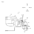
Fig. 2] Fig. 2 is a left side view partially in section of an outdrive device according to the embodiment of the present invention. - [
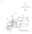
Fig. 3] Fig. 3 is a right side view partially in section of the outdrive device according to the embodiment of the present invention. - [
Fig. 4] Fig. 4 is a drawing of an operation device. - [
Fig. 5] Fig. 5 is a block diagram of a control device. - [
Fig. 6] Fig. 6 is a flow chart of a calculation method of propulsion powers and directions of left and right outdrive devices. - [
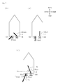
Fig. 7] Fig. 7(A) is a drawing of oblique sailing component propulsion power vectors of the outdrive devices.Fig. 7(B) is a drawing of turning component propulsion power vectors of the outdrive devices.Fig. 7(C) is a drawing of composition vectors of the outdrive devices. - [
Fig. 8] Fig. 8 is a plan view of a rotation angle of the outdrive device. - [
Fig. 9] Fig. 9 is a graph of relation of the angle of the composition vector and the rotation angle of the outdrive device. - [
Fig. 10] Fig. 10 is a plan view of the rotation angle of the outdrive device. - [
Fig. 11] Fig. 11 is a graph of relation of the rotation angle of the outdrive device and a reduction rate of an engine rotation speed. -
- 1 ship maneuvering device
- 2 hull
- 3A and 3B engines
- 4A and 4B rotation speed changing actuators
- 10A and 10B outdrive devices
- 15A and 15B screw propellers
- 16A and 16B forward/reverse switching clutches
- 17A and 17B hydraulic steering actuators
- 21 joystick (operation means)
- 31 control device
- 39 operation amount detection sensor (operation amount detection means)
- TAtrans and TBtrans oblique sailing component propulsion power vectors
- Tarot and TBrot turning component propulsion power vectors
- TA and TB composition vectors
- β angles of composition vectors
- θA and θB rotation angles of outdrive devices
- Firstly, an explanation will be given on a ship maneuvering device according to an embodiment of the present invention.
- As shown in
Figs. 1 ,2 and3 , aship maneuvering device 1 has a pair of left andright engines speed changing actuators right engines right outdrive devices right engines screw propellers hull 2, forward/reverse switching clutches engines screw propellers hydraulic steering actuators outdrive devices hydraulic steering actuators joystick 21, accelerator levers 22A and 22B and anoperation wheel 23 as operation means setting a traveling direction of the ship, an operation amount detection sensor 39 (seeFig. 5 ) as an operation amount detection means detecting an operation amount of thejoystick 21, operationamount detection sensor Fig. 5 ) as operation amount detection means detecting operation amounts of the accelerator levers 22A and 22B, an operation amount detection sensor 44 (seeFig. 5 ) as an operation amount detection means detecting an operation amount of theoperation wheel 23, and a control device 31 (seeFig. 5 ) controlling the rotationspeed changing actuators reverse switching clutches hydraulic steering actuators joystick 21, the accelerator levers 22A and 22B and theoperation wheel 23. - The
engines hull 2 as a pair laterally, and are connected to theoutdrive devices engines output shafts - The rotation
speed changing actuators engines - The
outdrive devices screw propellers hull 2, and are provided outside the rear portion of thehull 2 as a pair laterally. The pair of left andright outdrive devices right engines outdrive devices hull 2 so as to make thehull 2 turn. Theoutdrive devices input shafts 11A and 11B, the forward/reverse switching clutches drive shafts final output shaft 14A and 14B, and therotating screw propellers - The
input shafts 11A and 11B transmit rotation power. In detail, theinput shafts 11A and 11B transmit rotation power of theengines output shafts engines universal joints reverse switching clutches input shafts 11A and 11B is connected to corresponding one of theuniversal joints output shafts engines reverse switching clutches - The forward/
reverse switching clutches engines rotating screw propellers reverse switching clutches engines input shafts 11A and 11B and the like, to forward or reverse direction. The forward/reverse switching clutches input shafts 11A and 11B is pressed against the disc plates of the forward bevel gears or the reverse bevel gears so as to switch the rotation direction. - The
drive shafts drive shafts engines reverse switching clutches final output shaft 14A and 14B. A bevel gear provided at one of ends of each of thedrive shafts reverse switching clutches final output shaft 14A and 14B. - The
final output shaft 14A and 14B transmit the rotation power. In detail, thefinal output shaft 14A and 14B are rotation shafts which transmit the rotation power of theengines drive shafts screw propellers final output shaft 14A and 14B is meshed with the bevel gear of corresponding one of thedrive shafts screw propellers - The
screw propellers screw propellers engines final output shaft 14A and 14B and the like so that a plurality of blades arranged around the rotation shafts paddle surrounding water, whereby the propulsion power is generated. - The
hydraulic steering actuators arms outdrive devices hydraulic steering actuators control device 31. - The
hydraulic steering actuators hydraulic steering actuators - The
joystick 21 as the operation means is a device determining the traveling direction of the ship, and is provided near an operator's seat of thehull 2. A plane operation surface of thejoystick 21 is an oblique sailingcomponent determination part 21a, and a torsion operation surface thereof is a turningcomponent determination part 21b. - The
joystick 21 can be moved free within the operation surface parallel to an X-Y plane shown inFig. 4 , and a center of the operation surface is used as a neutral starting point. Longitudinal and lateral directions in the operation surface correspond to the traveling direction, and an inclination amount of thejoystick 21 corresponds to a target hull speed. The target hull speed is increased corresponding to increase of the inclination amount of thejoystick 21. - The torsion operation surface is provided with the
joystick 21, and by twisting thejoystick 21 concerning a Z axis extended substantially perpendicularly to the plane operation surface as a turning axis, a turning speed can be changed. A torsion amount of thejoystick 21 corresponds to a target turning speed. A maximum target lateral turning speed is set at fixed turning angle positions of thejoystick 21. - The accelerator levers 22A and 22B as the operation means are devices determining the target hull speed of the ship, and are provided near the operator's seat of the
hull 2. The twoaccelerator levers right engines engine 3A is changed by operating theaccelerator lever 22A, and the rotation speed of theengine 3B is changed by operating theaccelerator lever 22B. - The
operation wheel 23 as the operation means is a device determining the traveling direction of the ship, and is provided near the operator's seat of thehull 2. The traveling direction is changed widely following increase of a rotation amount of theoperation wheel 23. - A correction control start switch 42 (see
Fig. 5 ) is a switch for starting correction control of turning action of thehull 2. - The correction control start
switch 42 is provided near thejoystick 21 and is connected to thecontrol device 31. - Next, an explanation will be given on various kinds of detection means referring to
Fig. 5 . - Rotation
speed detection sensors engines engines - An
elevation angle sensor 36 as an elevation angle detection means is a means for detecting an elevation angle α of thehull 2. The elevation angle indicates inclination of the hull in the water concerning a flow. - A
hull speed sensor 37 as a hull speed detection means is a means for detecting a hull speed V, and is an electromagnetic log, a Doppler sonar or a GPS for example. - Lateral rotation
angle detection sensors outdrive devices angle detection sensors hydraulic steering actuators outdrive devices hydraulic steering actuators - The operation
amount detection sensor 39 as the operation amount detection means is a sensor for detecting the operation amount in the plane operation surface and the operation amount in the torsion operation surface of thejoystick 21. The operationamount detection sensor 39 detects an inclination angle and an inclination direction of thejoystick 21. The operationamount detection sensor 39 detects the torsion amount of thejoystick 21. - The operation
amount detection sensors amount detection sensors - The operation
amount detection sensor 44 as the operation amount detection means is a sensor for detecting the operation amount of theoperation wheel 23. The operationamount detection sensor 44 detects the rotation amount of theoperation wheel 23. - Outdrive device rotation
speed detection sensors outdrive devices screw propellers outdrive devices final output shaft 14A and 14B. The outdrive device rotationspeed detection sensors - The
control device 31 controls the rotationspeed changing actuators reverse switching clutches hydraulic steering actuators joystick 21. Thecontrol device 31 is connected respectively to the rotationspeed changing actuators reverse switching clutches hydraulic steering actuators joystick 21, the accelerator levers 22A and 22B, theoperation wheel 23, the rotationspeed detection sensors elevation angle sensor 36, thehull speed sensor 37, the lateral rotationangle detection sensors amount detection sensor 39, the operationamount detection sensors amount detection sensor 44, and the outdrive device rotationspeed detection sensors control device 31 includes a calculation means 32 having a CPU (central processing unit) and a storage means 33 such as a ROM, a RAM or a HDD. - Next, an explanation will be given on a method for calculating the propulsion powers and directions of the left and
right outdrive devices control device 31 referring toFig. 6 . - Firstly, an operation amount of the
joystick 21 is detected (step S10), and based on the operation amount of thejoystick 21, oblique sailing component propulsion power vectors TAtrans and TBtrans for the oblique sailing and turning component propulsion power vectors TArot and TBrot for the turning of the left andright outdrive devices - The operation amount of the
joystick 21 is the inclination angle, the inclination direction and a torsion amount of thejoystick 21, and detected with the operationamount detection sensor 39. Then, based on the operation amounts, thecontrol device 31 calculates the oblique sailing component propulsion power vectors TAtrans and TBtrans for the oblique sailing and the turning component propulsion power vectors TArot and TBrot for the turning of the left andright outdrive devices right outdrive devices Fig. 7(A) . The turning component propulsion power vectors TArot and TBrot of the left andright outdrive devices Fig. 7(B) . - Next, the oblique sailing component propulsion power vectors TAtrans and TBtrans and the turning component propulsion power vectors TArot and TBrot of the left and
right outdrive devices right outdrive devices - As shown in
Fig. 7(C) , vectors TA and TB are calculated by composing the oblique sailing component propulsion power vectors TAtrans and TBtrans and the turning component propulsion power vectors TArot and TBrot of the left andright outdrive devices - Next, based on norms of the composited vectors TA and TB, the
control device 31 calculates a rotation speed N of each of the left andright engines reverse switching clutches right engines outdrive devices hydraulic steering actuators - Next, an explanation will be given on a process of restriction of the lateral rotation angles of the pair of left and
right outdrive devices right outdrive devices outdrive device 10A is described. - When the angle (direction) β of the composition vectors TA is over a predetermined angle range of the
outdrive device 10A at the step S50 in the flow chart, theoutdrive device 10A is controlled so as to be at a predetermined limiting angle mode. - Herein, the predetermined angle range is a range shown with slashes in
Fig. 8 , and is an angle range in which theoutdrive device 10A can be rotated. Since thehydraulic steering actuator 17A is constructed by a hydraulic cylinder and its rotation range is limited, the predetermined angle range is provided. When the predetermined angle range is referred to as θ1, a limiting angle is referred to as α, and the rear side is regarded as 0°, the relation thereof is -α < θ1 ≦ α. Since the rotation of theengine 3A can be switched between forward and reverse rotations with the forward/reverse switching clutch 16A, centering on the front side, in other words, 180° (-180°), the lateral angle is -180° < θ1 ≦ 180°-(-α), 180°-α < θ1 ≦ 180°. For example, when α is 30°, the predetermined angle range is -180° < θ1 ≦ -150°, -30° < θ1 ≦ 30°, 150° < θ1 ≦ 180°. - Next, an explanation will be given on the limiting angle mode.
- In the limiting angle mode, for obtaining smooth action following the operation of the
joystick 21, the driving is performed with reduced propulsion power. Namely, the engine rotation speed NA is reduced to a set rotation speed Nset. In the limiting angle mode, the rotation angle θA of theoutdrive device 10A is fixed at a state of a predetermined limiting angle. Concretely, by the angle (direction) β of the composition vectors TA determined with thecontrol device 31, the lateral rotation angle θA of theoutdrive device 10A is determined. As shown inFig. 9 , in the case in which an X axis indicates the angle β of the composition vector TA and a Y axis indicates the lateral rotation angle θA of theoutdrive device 10A, when the angle β of the composition vector T is within a range of -180°-(-α) < β ≦ -90°, the lateral rotation angle θA of theoutdrive device 10A is -180°-(-α). When the angle β of the composition vector T is within a range of -90° < β ≦ -α, the lateral rotation angle θA of theoutdrive device 10A is (-α). When the angle β of the composition vector TA is within a range of α < β≦ 90°, the lateral rotation angle θA of theoutdrive device 10A is α. When the angle β of the composition vector TA is within a range of 90° < β ≦ 180°-α, the lateral rotation angle θA of theoutdrive device 10A is 180°-α. - As shown in
Fig. 9 , in the limiting angle mode, a play tolerance (hysteresis) is set so as to prevent frequent change of the rotation angle θA of theoutdrive device 10A. - In the case in which the angle β of the composition vector TA is within a range of -180°-(-α) < β ≦ -90°, when the angle β of the composition vector TA is larger than -90°+γ, the rotation angle θA of the
outdrive device 10A is (-α). In the case in which the angle β of the composition vector TA is within a range of -90° < β ≦ -α, when the angle β of the composition vector TA is not more than -90°-γ, the rotation angle θA of theoutdrive device 10A is -180°-(-α). - In the case in which the angle β of the composition vector TA is within a range of α < β ≦ 90°, when the angle β of the composition vector TA is larger than 90°+γ, the rotation angle θA of the
outdrive device 10A is 180°-α. In the case in which the angle β of the composition vector TA is within a range of 90° < β ≦ 180°-α, when the direction of the composition vector TA is not more than 90°-γ, the rotation angle θA of theoutdrive device 10A is α. - In the limiting angle mode, the engine rotation speed NA of the
engine 3A may alternatively be reduced following reduction of a minor angle between the direction of the composition vector TA and the lateral direction of thehull 2. Following the reduction of the angle between the direction of the composition vector TA and the lateral direction of the hull (90° and -90°), that is, following approach of the angle β of the composition vector TA to 90° or -90°, the engine rotation speed NA of theengine 3A is reduced. - As shown in
Figs. 10 and11 , in the limiting angle mode, by increasing a rotation reduction rate of theengine 3A, the engine rotation speed NA is reduced. - An area shown with slashes in
Fig. 10 is a rotation speed reduction area in which the engine rotation speed NA is reduced gradually, and a colored area is areduction rate 100% area in which the reduction rate of the engine rotation speed NA is 100%. - Concretely, as shown in
Fig. 11 , within a range larger than -180°-(-α) and not more than Φ1, the reduction rate is increased following the increase of the angle β of the composition vector TA, and at Φ1, the reduction rate is 100%, that is, the engine rotation speed NA is a low idling rotation speed. - When the angle β of the composition vector TA is larger than Φ1 and not more than Φ2, the reduction rate is maintained at 100%.
- When the angle β of the composition vector TA is larger than Φ2 and not more than -α, the reduction rate is reduced following the increase of the angle β. At -α, the reduction rate is 0%, that is, the engine rotation speed NA is the engine rotation speed calculated at the step S40.
- Herein, Φ1 and Φ2 are angles are linearly symmetrical with -90°. For example, when Φ1 is -100°, Φ2 is -80°.
- When the angle β3 of the composition vector TA is larger than α and not more than Φ3, the reduction rate is increased following the increase of the angle β. At Φ3, the reduction rate is 100%, that is, the engine rotation speed NA is the low idling rotation speed.
- When the angle β3 of the composition vector TA is larger than Φ3 and not more than Φ4, the reduction rate is maintained at 100%.
- When the angle β3 of the composition vector TA is larger than Φ4 and not more than 180°-α, the reduction rate is reduced following the increase of the angle β. At 180°-α, the reduction rate is 0%, that is, the engine rotation speed NA is the engine rotation speed calculated at the step S40.
- Herein, Φ3 and Φ4 are angles are linearly symmetrical with 90°. For example, when Φ3 is 80°, Φ4 is 100°.
Φ1, Φ2, Φ3 and Φ4 can be changed within the ranges of -180°-(-α) ≦ Φ1 < -90°, -90° ≦ Φ2 < -α, α ≦ Φ3 < 90°, and 90° ≦ Φ4 < 180°-α. - As mentioned above, the
ship maneuvering device 1 has the pair of left andright engines speed changing actuators right engines right outdrive devices right engines screw propellers hull 2, the forward/reverse switching clutches engines screw propellers hydraulic steering actuators right outdrive devices joystick 21 setting the traveling direction of the ship, the operationamount detection sensor 39 detecting the operation amount of thejoystick 21, and thecontrol device 31 controlling the rotationspeed changing actuators reverse switching clutches hydraulic steering actuators joystick 21. From the operation amount of thejoystick 21, thecontrol device 31 calculates the oblique sailing component propulsion power vectors TAtrans and TBtrans for the oblique sailing of the left andright outdrive devices right outdrive devices right outdrive devices - According to the construction, in comparison with the case of calculating the propulsion powers and the directions of the left and
right outdrive devices right outdrive devices - When the angle β of the composition vector TA (TB) is over the predetermined angle range of the
outdrive devices outdrive devices - According to the construction, even if the angle β of the composition vector TA (TB) is over the predetermined angle range of the
outdrive device 10A (10B), the steering of theoutdrive devices 10A (10B) can be corrected. - When the angle β of the composition vector TA (TB) is over the predetermined angle range of the
outdrive device 10A (10B), the rotation angle θA (θB) of theoutdrive device 10A (10B) is fixed at the state of the predetermined limiting angle. - According to the construction, when the angle of the composition vector TA (TB) is over the predetermined angle range of the
outdrive devices 10A (10B), frequent change of the rotation angle and frequent switching of forward/reverse rotation of theoutdrive device 10A (10B) is prevented. - When the angle β of the composition vector TA (TB) is over the predetermined angle range of the
outdrive device 10A (10B), the engine rotation speed NA (NB) of theengine 3A (3B) is reduced following the reduction of the minor angle between the direction β of the composition vector TA (TB) and the lateral direction of the hull. - According to the construction, when the angle β of the composition vector TA (TB) is over the predetermined angle range of the
outdrive devices 10A (10B), the switching of forward/reverse rotation of theoutdrive devices 10A (10B) can be performed smoothly. - The present invention can be used for a ship having an inboard motor in which a pair of left and right engines are arranged inside a hull and power is transmitted to a pair of left and right outdrive devices arranged outside the hull.
Claims (4)
- A ship maneuvering device comprising:a pair of left and right engines;rotation speed changing actuators independently changing engine rotation speeds of the pair of left and right engines;a pair of left and right outdrive devices respectively connected to the pair of left and right engines and rotating screw propellers so as to propel a hull;forward/reverse switching clutches disposed between the engines and the screw propellers;a pair of left and right steering actuators respectively independently rotating the pair of left and right outdrive devices laterally within a predetermined angle range;an operation means setting a traveling direction of a ship;an operation amount detection means detecting the operation amount of the operation means; anda control device controlling the rotation speed changing actuators, the forward/reverse switching clutches, and the steering actuators so as to travel to a direction set by the operation means,characterized in thatthe control device calculates oblique sailing component propulsion power vectors for oblique sailing of the left and right outdrive devices and turning component propulsion power vectors for the turning from the operation amount of the operation means, and composes the oblique sailing component propulsion power vectors and the turning component propulsion power vectors of the left and right outdrive devices so as to calculates composition vectors, thereby calculating propulsion powers and directions of the left and right outdrive devices.
- The ship maneuvering device according to claim 1, wherein when directions of the composition vector is over a predetermined angle range of the outdrive device, the outdrive device is controlled so as to be made a predetermined limiting angle mode and the engine rotation speed is reduced to a set rotation speed.
- The ship maneuvering device according to claim 1 or 2, wherein when the direction of the composition vector is over a predetermined angle range of the outdrive device, a rotation angle of the outdrive device is fixed at a state of a predetermined limiting angle.
- The ship maneuvering device according to claim 1, wherein when a direction of the composition vector is over a predetermined angle range of the outdrive device, the engine rotation speed of the engine is reduced following reduction of a minor angle between the direction of the composition vector and a lateral direction of the hull.
Applications Claiming Priority (2)
| Application Number | Priority Date | Filing Date | Title |
|---|---|---|---|
| JP2011146743A JP5809862B2 (en) | 2011-06-30 | 2011-06-30 | Ship handling equipment |
| PCT/JP2012/058456 WO2013001876A1 (en) | 2011-06-30 | 2012-03-29 | Ship maneuvering device |
Publications (3)
| Publication Number | Publication Date |
|---|---|
| EP2727818A1 true EP2727818A1 (en) | 2014-05-07 |
| EP2727818A4 EP2727818A4 (en) | 2015-05-20 |
| EP2727818B1 EP2727818B1 (en) | 2019-05-08 |
Family
ID=47423787
Family Applications (1)
| Application Number | Title | Priority Date | Filing Date |
|---|---|---|---|
| EP12804380.9A Active EP2727818B1 (en) | 2011-06-30 | 2012-03-29 | Ship maneuvering device |
Country Status (4)
| Country | Link |
|---|---|
| US (1) | US9180951B2 (en) |
| EP (1) | EP2727818B1 (en) |
| JP (1) | JP5809862B2 (en) |
| WO (1) | WO2013001876A1 (en) |
Cited By (1)
| Publication number | Priority date | Publication date | Assignee | Title |
|---|---|---|---|---|
| CN110177741A (en) * | 2016-11-14 | 2019-08-27 | 沃尔沃遍达公司 | Method for operating the ship including multiple propulsion units |
Families Citing this family (9)
| Publication number | Priority date | Publication date | Assignee | Title |
|---|---|---|---|---|
| WO2014119423A1 (en) * | 2013-02-01 | 2014-08-07 | ヤンマー株式会社 | Steering mechanism for outdrive device, and vessel provided with steering mechanism for outdrive device |
| JP5965849B2 (en) * | 2013-02-01 | 2016-08-10 | ヤンマー株式会社 | Steering mechanism for outdrive device and ship equipped with steering mechanism for outdrive device |
| FR3011225B1 (en) * | 2013-10-01 | 2015-11-06 | Dcns | NAVAL PLATFORM HAVING AT LEAST ONE HULL EQUIPPED WITH ORIENTABLE PROPELLERS |
| JP6430985B2 (en) * | 2016-03-25 | 2018-11-28 | ヤンマー株式会社 | Ship maneuvering apparatus and ship equipped with the same |
| US10472039B2 (en) | 2016-04-29 | 2019-11-12 | Brp Us Inc. | Hydraulic steering system for a watercraft |
| US10232925B1 (en) | 2016-12-13 | 2019-03-19 | Brunswick Corporation | System and methods for steering a marine vessel |
| KR101884534B1 (en) * | 2016-12-19 | 2018-08-01 | 한국해양과학기술원 | A hull pressure fluctuation reduction method for a ship with twin propellers using propeller rotation angle control |
| CN108762263B (en) * | 2018-05-22 | 2021-07-23 | 中国船舶工业集团公司第七0八研究所 | A vector motion control method for a double-machine double-water-jet propulsion boat |
| US11628920B2 (en) | 2021-03-29 | 2023-04-18 | Brunswick Corporation | Systems and methods for steering a marine vessel |
Family Cites Families (9)
| Publication number | Priority date | Publication date | Assignee | Title |
|---|---|---|---|---|
| JPH01285486A (en) | 1988-05-12 | 1989-11-16 | Yanmar Diesel Engine Co Ltd | Maneuvering device for ship |
| US6848382B1 (en) | 2002-12-23 | 2005-02-01 | Joannes Raymond Mari Bekker | Portable dynamic positioning system with self-contained electric thrusters |
| US20070017426A1 (en) * | 2003-12-16 | 2007-01-25 | Hirotaka Kaji | Marine vessel maneuvering supporting apparatus, marine vessel including the marine vessel maneuvering supporting apparatus, and marine vessel maneuvering supporting method |
| JP4907935B2 (en) * | 2005-09-20 | 2012-04-04 | ヤマハ発動機株式会社 | Ship |
| US7267068B2 (en) * | 2005-10-12 | 2007-09-11 | Brunswick Corporation | Method for maneuvering a marine vessel in response to a manually operable control device |
| JP4256418B2 (en) * | 2006-10-05 | 2009-04-22 | 三菱電機株式会社 | Ship cruise control system |
| US20090197486A1 (en) * | 2008-01-31 | 2009-08-06 | Ab Volvo Penta | Method and system for maneuvering aquatic vessels |
| JP5481059B2 (en) | 2008-11-28 | 2014-04-23 | ヤマハ発動機株式会社 | Maneuvering support apparatus and ship equipped with the same |
| JP5243978B2 (en) | 2009-01-27 | 2013-07-24 | ヤマハ発動機株式会社 | Marine propulsion system and ship maneuvering method |
-
2011
- 2011-06-30 JP JP2011146743A patent/JP5809862B2/en active Active
-
2012
- 2012-03-29 WO PCT/JP2012/058456 patent/WO2013001876A1/en not_active Ceased
- 2012-03-29 US US14/129,823 patent/US9180951B2/en active Active
- 2012-03-29 EP EP12804380.9A patent/EP2727818B1/en active Active
Cited By (3)
| Publication number | Priority date | Publication date | Assignee | Title |
|---|---|---|---|---|
| CN110177741A (en) * | 2016-11-14 | 2019-08-27 | 沃尔沃遍达公司 | Method for operating the ship including multiple propulsion units |
| CN110177741B (en) * | 2016-11-14 | 2021-05-25 | 沃尔沃遍达公司 | Method for operating a vessel comprising a plurality of propulsion units |
| US11072409B2 (en) | 2016-11-14 | 2021-07-27 | Volvo Penta Corporation | Method for operating a marine vessel comprising a plurality of propulsion units |
Also Published As
| Publication number | Publication date |
|---|---|
| WO2013001876A1 (en) | 2013-01-03 |
| US9180951B2 (en) | 2015-11-10 |
| EP2727818B1 (en) | 2019-05-08 |
| US20140174331A1 (en) | 2014-06-26 |
| EP2727818A4 (en) | 2015-05-20 |
| JP2013014174A (en) | 2013-01-24 |
| JP5809862B2 (en) | 2015-11-11 |
Similar Documents
| Publication | Publication Date | Title |
|---|---|---|
| EP2727818B1 (en) | Ship maneuvering device | |
| US9193431B2 (en) | Ship steering device and ship steering method | |
| EP2727817B1 (en) | Ship maneuvering device | |
| EP3437986B1 (en) | Method of using a ship handling device | |
| US8589004B1 (en) | Boat propulsion system and method for controlling boat propulsion system | |
| JP5133637B2 (en) | Ship | |
| US10766589B1 (en) | System for and method of controlling watercraft | |
| JP6667935B2 (en) | Ship | |
| JP5764411B2 (en) | Ship handling equipment | |
| JP6421111B2 (en) | Maneuvering equipment | |
| JP2019516623A (en) | Method and control device for operating a ship | |
| WO2016063606A1 (en) | Ship handling device | |
| EP3434580B1 (en) | Ship | |
| EP3434582B1 (en) | Ship | |
| US10661872B1 (en) | System for and method of controlling watercraft | |
| JP2016083974A (en) | Ship steering device |
Legal Events
| Date | Code | Title | Description |
|---|---|---|---|
| PUAI | Public reference made under article 153(3) epc to a published international application that has entered the european phase |
Free format text: ORIGINAL CODE: 0009012 |
|
| 17P | Request for examination filed |
Effective date: 20140130 |
|
| AK | Designated contracting states |
Kind code of ref document: A1 Designated state(s): AL AT BE BG CH CY CZ DE DK EE ES FI FR GB GR HR HU IE IS IT LI LT LU LV MC MK MT NL NO PL PT RO RS SE SI SK SM TR |
|
| DAX | Request for extension of the european patent (deleted) | ||
| RIC1 | Information provided on ipc code assigned before grant |
Ipc: B63H 25/42 20060101AFI20150312BHEP Ipc: B63H 20/00 20060101ALI20150312BHEP Ipc: B63H 21/21 20060101ALI20150312BHEP |
|
| RA4 | Supplementary search report drawn up and despatched (corrected) |
Effective date: 20150421 |
|
| RIC1 | Information provided on ipc code assigned before grant |
Ipc: B63H 25/42 20060101AFI20150415BHEP Ipc: B63H 20/00 20060101ALI20150415BHEP Ipc: B63H 21/21 20060101ALI20150415BHEP |
|
| STAA | Information on the status of an ep patent application or granted ep patent |
Free format text: STATUS: EXAMINATION IS IN PROGRESS |
|
| 17Q | First examination report despatched |
Effective date: 20171220 |
|
| GRAP | Despatch of communication of intention to grant a patent |
Free format text: ORIGINAL CODE: EPIDOSNIGR1 |
|
| STAA | Information on the status of an ep patent application or granted ep patent |
Free format text: STATUS: GRANT OF PATENT IS INTENDED |
|
| INTG | Intention to grant announced |
Effective date: 20180904 |
|
| GRAJ | Information related to disapproval of communication of intention to grant by the applicant or resumption of examination proceedings by the epo deleted |
Free format text: ORIGINAL CODE: EPIDOSDIGR1 |
|
| STAA | Information on the status of an ep patent application or granted ep patent |
Free format text: STATUS: EXAMINATION IS IN PROGRESS |
|
| GRAP | Despatch of communication of intention to grant a patent |
Free format text: ORIGINAL CODE: EPIDOSNIGR1 |
|
| STAA | Information on the status of an ep patent application or granted ep patent |
Free format text: STATUS: GRANT OF PATENT IS INTENDED |
|
| INTC | Intention to grant announced (deleted) | ||
| RIN1 | Information on inventor provided before grant (corrected) |
Inventor name: HARA NAOHIRO Inventor name: HITACHI JUNICHI |
|
| INTG | Intention to grant announced |
Effective date: 20181130 |
|
| GRAS | Grant fee paid |
Free format text: ORIGINAL CODE: EPIDOSNIGR3 |
|
| GRAA | (expected) grant |
Free format text: ORIGINAL CODE: 0009210 |
|
| STAA | Information on the status of an ep patent application or granted ep patent |
Free format text: STATUS: THE PATENT HAS BEEN GRANTED |
|
| AK | Designated contracting states |
Kind code of ref document: B1 Designated state(s): AL AT BE BG CH CY CZ DE DK EE ES FI FR GB GR HR HU IE IS IT LI LT LU LV MC MK MT NL NO PL PT RO RS SE SI SK SM TR |
|
| REG | Reference to a national code |
Ref country code: GB Ref legal event code: FG4D |
|
| REG | Reference to a national code |
Ref country code: CH Ref legal event code: EP Ref country code: AT Ref legal event code: REF Ref document number: 1129736 Country of ref document: AT Kind code of ref document: T Effective date: 20190515 |
|
| REG | Reference to a national code |
Ref country code: DE Ref legal event code: R096 Ref document number: 602012059949 Country of ref document: DE Ref country code: IE Ref legal event code: FG4D |
|
| REG | Reference to a national code |
Ref country code: NL Ref legal event code: FP |
|
| REG | Reference to a national code |
Ref country code: LT Ref legal event code: MG4D |
|
| PG25 | Lapsed in a contracting state [announced via postgrant information from national office to epo] |
Ref country code: HR Free format text: LAPSE BECAUSE OF FAILURE TO SUBMIT A TRANSLATION OF THE DESCRIPTION OR TO PAY THE FEE WITHIN THE PRESCRIBED TIME-LIMIT Effective date: 20190508 Ref country code: LT Free format text: LAPSE BECAUSE OF FAILURE TO SUBMIT A TRANSLATION OF THE DESCRIPTION OR TO PAY THE FEE WITHIN THE PRESCRIBED TIME-LIMIT Effective date: 20190508 Ref country code: ES Free format text: LAPSE BECAUSE OF FAILURE TO SUBMIT A TRANSLATION OF THE DESCRIPTION OR TO PAY THE FEE WITHIN THE PRESCRIBED TIME-LIMIT Effective date: 20190508 Ref country code: FI Free format text: LAPSE BECAUSE OF FAILURE TO SUBMIT A TRANSLATION OF THE DESCRIPTION OR TO PAY THE FEE WITHIN THE PRESCRIBED TIME-LIMIT Effective date: 20190508 Ref country code: PT Free format text: LAPSE BECAUSE OF FAILURE TO SUBMIT A TRANSLATION OF THE DESCRIPTION OR TO PAY THE FEE WITHIN THE PRESCRIBED TIME-LIMIT Effective date: 20190908 Ref country code: NO Free format text: LAPSE BECAUSE OF FAILURE TO SUBMIT A TRANSLATION OF THE DESCRIPTION OR TO PAY THE FEE WITHIN THE PRESCRIBED TIME-LIMIT Effective date: 20190808 Ref country code: AL Free format text: LAPSE BECAUSE OF FAILURE TO SUBMIT A TRANSLATION OF THE DESCRIPTION OR TO PAY THE FEE WITHIN THE PRESCRIBED TIME-LIMIT Effective date: 20190508 Ref country code: SE Free format text: LAPSE BECAUSE OF FAILURE TO SUBMIT A TRANSLATION OF THE DESCRIPTION OR TO PAY THE FEE WITHIN THE PRESCRIBED TIME-LIMIT Effective date: 20190508 |
|
| PG25 | Lapsed in a contracting state [announced via postgrant information from national office to epo] |
Ref country code: BG Free format text: LAPSE BECAUSE OF FAILURE TO SUBMIT A TRANSLATION OF THE DESCRIPTION OR TO PAY THE FEE WITHIN THE PRESCRIBED TIME-LIMIT Effective date: 20190808 Ref country code: GR Free format text: LAPSE BECAUSE OF FAILURE TO SUBMIT A TRANSLATION OF THE DESCRIPTION OR TO PAY THE FEE WITHIN THE PRESCRIBED TIME-LIMIT Effective date: 20190809 Ref country code: LV Free format text: LAPSE BECAUSE OF FAILURE TO SUBMIT A TRANSLATION OF THE DESCRIPTION OR TO PAY THE FEE WITHIN THE PRESCRIBED TIME-LIMIT Effective date: 20190508 Ref country code: RS Free format text: LAPSE BECAUSE OF FAILURE TO SUBMIT A TRANSLATION OF THE DESCRIPTION OR TO PAY THE FEE WITHIN THE PRESCRIBED TIME-LIMIT Effective date: 20190508 |
|
| REG | Reference to a national code |
Ref country code: AT Ref legal event code: MK05 Ref document number: 1129736 Country of ref document: AT Kind code of ref document: T Effective date: 20190508 |
|
| PG25 | Lapsed in a contracting state [announced via postgrant information from national office to epo] |
Ref country code: AT Free format text: LAPSE BECAUSE OF FAILURE TO SUBMIT A TRANSLATION OF THE DESCRIPTION OR TO PAY THE FEE WITHIN THE PRESCRIBED TIME-LIMIT Effective date: 20190508 Ref country code: EE Free format text: LAPSE BECAUSE OF FAILURE TO SUBMIT A TRANSLATION OF THE DESCRIPTION OR TO PAY THE FEE WITHIN THE PRESCRIBED TIME-LIMIT Effective date: 20190508 Ref country code: RO Free format text: LAPSE BECAUSE OF FAILURE TO SUBMIT A TRANSLATION OF THE DESCRIPTION OR TO PAY THE FEE WITHIN THE PRESCRIBED TIME-LIMIT Effective date: 20190508 Ref country code: CZ Free format text: LAPSE BECAUSE OF FAILURE TO SUBMIT A TRANSLATION OF THE DESCRIPTION OR TO PAY THE FEE WITHIN THE PRESCRIBED TIME-LIMIT Effective date: 20190508 Ref country code: SK Free format text: LAPSE BECAUSE OF FAILURE TO SUBMIT A TRANSLATION OF THE DESCRIPTION OR TO PAY THE FEE WITHIN THE PRESCRIBED TIME-LIMIT Effective date: 20190508 Ref country code: DK Free format text: LAPSE BECAUSE OF FAILURE TO SUBMIT A TRANSLATION OF THE DESCRIPTION OR TO PAY THE FEE WITHIN THE PRESCRIBED TIME-LIMIT Effective date: 20190508 |
|
| REG | Reference to a national code |
Ref country code: DE Ref legal event code: R097 Ref document number: 602012059949 Country of ref document: DE |
|
| PG25 | Lapsed in a contracting state [announced via postgrant information from national office to epo] |
Ref country code: SM Free format text: LAPSE BECAUSE OF FAILURE TO SUBMIT A TRANSLATION OF THE DESCRIPTION OR TO PAY THE FEE WITHIN THE PRESCRIBED TIME-LIMIT Effective date: 20190508 Ref country code: IT Free format text: LAPSE BECAUSE OF FAILURE TO SUBMIT A TRANSLATION OF THE DESCRIPTION OR TO PAY THE FEE WITHIN THE PRESCRIBED TIME-LIMIT Effective date: 20190508 |
|
| PLBE | No opposition filed within time limit |
Free format text: ORIGINAL CODE: 0009261 |
|
| STAA | Information on the status of an ep patent application or granted ep patent |
Free format text: STATUS: NO OPPOSITION FILED WITHIN TIME LIMIT |
|
| PG25 | Lapsed in a contracting state [announced via postgrant information from national office to epo] |
Ref country code: TR Free format text: LAPSE BECAUSE OF FAILURE TO SUBMIT A TRANSLATION OF THE DESCRIPTION OR TO PAY THE FEE WITHIN THE PRESCRIBED TIME-LIMIT Effective date: 20190508 |
|
| 26N | No opposition filed |
Effective date: 20200211 |
|
| PG25 | Lapsed in a contracting state [announced via postgrant information from national office to epo] |
Ref country code: PL Free format text: LAPSE BECAUSE OF FAILURE TO SUBMIT A TRANSLATION OF THE DESCRIPTION OR TO PAY THE FEE WITHIN THE PRESCRIBED TIME-LIMIT Effective date: 20190508 |
|
| PG25 | Lapsed in a contracting state [announced via postgrant information from national office to epo] |
Ref country code: SI Free format text: LAPSE BECAUSE OF FAILURE TO SUBMIT A TRANSLATION OF THE DESCRIPTION OR TO PAY THE FEE WITHIN THE PRESCRIBED TIME-LIMIT Effective date: 20190508 |
|
| REG | Reference to a national code |
Ref country code: DE Ref legal event code: R082 Ref document number: 602012059949 Country of ref document: DE Representative=s name: JOSTARNDT PATENTANWALTS-AG, DE Ref country code: DE Ref legal event code: R081 Ref document number: 602012059949 Country of ref document: DE Owner name: YANMAR POWER TECHNOLOGY CO., LTD., JP Free format text: FORMER OWNER: YANMAR CO., LTD., OSAKA, JP |
|
| PG25 | Lapsed in a contracting state [announced via postgrant information from national office to epo] |
Ref country code: MC Free format text: LAPSE BECAUSE OF FAILURE TO SUBMIT A TRANSLATION OF THE DESCRIPTION OR TO PAY THE FEE WITHIN THE PRESCRIBED TIME-LIMIT Effective date: 20190508 |
|
| REG | Reference to a national code |
Ref country code: CH Ref legal event code: PL |
|
| REG | Reference to a national code |
Ref country code: NL Ref legal event code: HC Owner name: YANMAR POWER TECHNOLOGY CO, LTD.; JP Free format text: DETAILS ASSIGNMENT: CHANGE OF OWNER(S), CHANGE OF OWNER(S) NAME; FORMER OWNER NAME: YANMAR CO., LTD. Effective date: 20201126 |
|
| REG | Reference to a national code |
Ref country code: BE Ref legal event code: MM Effective date: 20200331 |
|
| PG25 | Lapsed in a contracting state [announced via postgrant information from national office to epo] |
Ref country code: LU Free format text: LAPSE BECAUSE OF NON-PAYMENT OF DUE FEES Effective date: 20200329 |
|
| PG25 | Lapsed in a contracting state [announced via postgrant information from national office to epo] |
Ref country code: IE Free format text: LAPSE BECAUSE OF NON-PAYMENT OF DUE FEES Effective date: 20200329 Ref country code: CH Free format text: LAPSE BECAUSE OF NON-PAYMENT OF DUE FEES Effective date: 20200331 Ref country code: LI Free format text: LAPSE BECAUSE OF NON-PAYMENT OF DUE FEES Effective date: 20200331 |
|
| PG25 | Lapsed in a contracting state [announced via postgrant information from national office to epo] |
Ref country code: BE Free format text: LAPSE BECAUSE OF NON-PAYMENT OF DUE FEES Effective date: 20200331 |
|
| PGFP | Annual fee paid to national office [announced via postgrant information from national office to epo] |
Ref country code: FR Payment date: 20210323 Year of fee payment: 10 Ref country code: NL Payment date: 20210319 Year of fee payment: 10 |
|
| PGFP | Annual fee paid to national office [announced via postgrant information from national office to epo] |
Ref country code: GB Payment date: 20210324 Year of fee payment: 10 Ref country code: DE Payment date: 20210319 Year of fee payment: 10 |
|
| PG25 | Lapsed in a contracting state [announced via postgrant information from national office to epo] |
Ref country code: MT Free format text: LAPSE BECAUSE OF FAILURE TO SUBMIT A TRANSLATION OF THE DESCRIPTION OR TO PAY THE FEE WITHIN THE PRESCRIBED TIME-LIMIT Effective date: 20190508 Ref country code: CY Free format text: LAPSE BECAUSE OF FAILURE TO SUBMIT A TRANSLATION OF THE DESCRIPTION OR TO PAY THE FEE WITHIN THE PRESCRIBED TIME-LIMIT Effective date: 20190508 |
|
| PG25 | Lapsed in a contracting state [announced via postgrant information from national office to epo] |
Ref country code: MK Free format text: LAPSE BECAUSE OF FAILURE TO SUBMIT A TRANSLATION OF THE DESCRIPTION OR TO PAY THE FEE WITHIN THE PRESCRIBED TIME-LIMIT Effective date: 20190508 Ref country code: IS Free format text: LAPSE BECAUSE OF FAILURE TO SUBMIT A TRANSLATION OF THE DESCRIPTION OR TO PAY THE FEE WITHIN THE PRESCRIBED TIME-LIMIT Effective date: 20190908 |
|
| REG | Reference to a national code |
Ref country code: DE Ref legal event code: R119 Ref document number: 602012059949 Country of ref document: DE |
|
| REG | Reference to a national code |
Ref country code: NL Ref legal event code: MM Effective date: 20220401 |
|
| GBPC | Gb: european patent ceased through non-payment of renewal fee |
Effective date: 20220329 |
|
| PG25 | Lapsed in a contracting state [announced via postgrant information from national office to epo] |
Ref country code: NL Free format text: LAPSE BECAUSE OF NON-PAYMENT OF DUE FEES Effective date: 20220401 Ref country code: GB Free format text: LAPSE BECAUSE OF NON-PAYMENT OF DUE FEES Effective date: 20220329 Ref country code: FR Free format text: LAPSE BECAUSE OF NON-PAYMENT OF DUE FEES Effective date: 20220331 Ref country code: DE Free format text: LAPSE BECAUSE OF NON-PAYMENT OF DUE FEES Effective date: 20221001 |