EP2727677A1 - Procédé pour dresser au moins une électrode d'érosion et système de dressage - Google Patents
Procédé pour dresser au moins une électrode d'érosion et système de dressage Download PDFInfo
- Publication number
- EP2727677A1 EP2727677A1 EP12190783.6A EP12190783A EP2727677A1 EP 2727677 A1 EP2727677 A1 EP 2727677A1 EP 12190783 A EP12190783 A EP 12190783A EP 2727677 A1 EP2727677 A1 EP 2727677A1
- Authority
- EP
- European Patent Office
- Prior art keywords
- workpiece
- sacrificial element
- holding device
- erosion
- erosion electrode
- Prior art date
- Legal status (The legal status is an assumption and is not a legal conclusion. Google has not performed a legal analysis and makes no representation as to the accuracy of the status listed.)
- Withdrawn
Links
Images


Classifications
-
- B—PERFORMING OPERATIONS; TRANSPORTING
- B23—MACHINE TOOLS; METAL-WORKING NOT OTHERWISE PROVIDED FOR
- B23H—WORKING OF METAL BY THE ACTION OF A HIGH CONCENTRATION OF ELECTRIC CURRENT ON A WORKPIECE USING AN ELECTRODE WHICH TAKES THE PLACE OF A TOOL; SUCH WORKING COMBINED WITH OTHER FORMS OF WORKING OF METAL
- B23H1/00—Electrical discharge machining, i.e. removing metal with a series of rapidly recurring electrical discharges between an electrode and a workpiece in the presence of a fluid dielectric
- B23H1/04—Electrodes specially adapted therefor or their manufacture
Definitions
- the invention relates to a method for recontouring at least one erosion electrode, which is arranged for erosive material removal by voltage pulses in the region of a workpiece to be machined. Furthermore, the invention relates to a Rekonturiersystem for recontouring at least one erosion electrode and the use of the method and Rekonturiersystems in the production of at least one sealing slot in an aerodynamic structural component.
- Erosion methods are abrasive manufacturing methods for conductive materials that are based on electrical discharges between at least one erosion electrode and a workpiece to be machined from an electrically conductive material.
- workpieces made of high-temperature-resistant alloys for example running or guide vanes for gas turbines, can often no longer be machined with machining processes without further ado. Therefore, such workpieces are given for erosion in a dielectric liquid such as mineral oil or deionized water or lapped with a dielectric liquid.
- an erosion electrode is arranged in the region to be machined of the workpiece, so that forms a narrow gap. If the gap is too large, there is no sufficient ionization of the dielectric fluid and thus no material removal.
- the erosion electrode and the workpiece will weld together.
- sparking sparks are generated between the erosion electrode and the workpiece, causing the material of the workpiece to melt or vaporize and be transported away by the dielectric fluid.
- the intensity, frequency, duration, length, gap width and polarity of the voltage pulses this results in different surface contours in the workpiece.
- the contour of the erosion electrode is decisive for the contour to be generated in the workpiece.
- the material of Erosion electrode usually depends on the material to be machined and is usually made of copper or graphite.
- a disadvantage of the known method is the fact that there is a certain risk that the workpiece will be damaged.
- no erosion electrodes can be recontoured, which protrude beyond the workpiece.
- such erosion electrodes are required, for example, to introduce open slots in the workpiece.
- the process is very complex, since the recontouring must be constantly monitored in order to set the electrical parameters correctly and to control the progress of the recontouring of the erosion electrode and the state of the workpiece.
- a first aspect of the invention relates to a method for recontouring at least one erosion electrode, the method being more flexible and time-consuming and cost-effective by arranging a sacrificial element between the erosion electrode and the workpiece, after which a recontouring of the erosion electrode by erosion occurs by applying a voltage a sacrificial element facing surface of the erosion electrode is performed on the sacrificial anode acting as a sacrificial element until the sacrificial element is eroded through.
- an erosion electrode as a sacrificial anode sacrificial element, which is eroded instead of the workpiece, wherein the recontouring is terminated only when the sacrificial element is completely eroded through in the region of the eroded surface of the erosion electrode.
- the recontouring of the erosion electrode thus takes place by the simultaneous erosion of the erosion electrode and the sacrificial element.
- a dielectric liquid is also to be provided between the erosion electrode and the sacrificial element during recontouring. The process can be force-free and therefore carried out without damaging the workpiece.
- the sacrificial element Due to the simple adaptability of the sacrificial element also a particularly simple and precise recontouring of the erosion electrode is made possible, which additionally results in significant savings of electrode material.
- the material and the geometry of the sacrificial element and the electrical parameters during recontouring are fundamentally selected such that it is ensured that the erosion electrode has the desired contour at the latest when the sacrificial element has been completely eroded through. Since the method according to the invention can be easily integrated into already established erosion methods and since neither an installation or removal of the erosion electrode, nor an expansion of the eroded sacrificial element are required, results in a particularly low time and personnel costs. In addition, the process is fully automated and can therefore be carried out in a particularly simple, reliable and precise manner.
- the erosion electrode penetrates into the workpiece arranged below the sacrificial element and that the erosion electrode has the correct contour when it penetrates into the workpiece. Accordingly, it is advantageously possible to dispense with additional measurement and control technology for process control.
- a plurality of individual sacrificial elements can be used to recontour an erosion electrode in principle.
- a plurality of sacrificial elements are used for recontouring a plurality of erosion electrodes.
- a sacrificial element is used for several Rekontur réellesvor réelle.
- the sacrificial element since the sacrificial element is completely eroded at each re-contouring, it must be re-aligned with respect to the erosion electrode for each subsequent re-contouring process in order to be able to face a surface of the eroding electrode which is to be recontoured in a correspondingly erodible surface of the sacrificial element.
- a sacrificial element is used only for a single Rekontur réellesclar and then replaced.
- the sacrificial element for recontouring the erosion electrode is arranged by means of a holding device between the erosion electrode and the workpiece and / or that the sacrificial element is left in the holding device after re-contouring.
- the sacrificial element can be positioned or removed in a simple manner for re-contouring between the workpiece and the erosion electrode.
- a holding device allows a particularly fast, precise and automatable arrangement and alignment of the sacrificial element, wherein preferably a holding device is used, in which the sacrificial element simply inserted or from which the consumed sacrificial element can be pulled out again.
- a holding device which has a holding device with corresponding sliding guide elements.
- Special time and cost advantages result from the fact that the sacrificial element is left in the holding device after re-contouring. This allows the workpiece arranged below the sacrificial element to be further processed immediately after the recontouring of the erosion electrode and the complete eroding of the sacrificial element by continued lowering of the erosion electrode, without the need for further installation or removal measures.
- the entire holding device is movably mounted on the erosion electrode and / or on the workpiece and as required between a rest position in which the sacrificial element is removed from the area between the erosion electrode and the workpiece, and a Rekontur istsposition in which the Victim element between the erosion electrode and the workpiece is arranged, pivoted, moved or otherwise moved.
- a sacrificial element with a polygonal and / or round and / or oval cross-sectional geometry is used.
- a rectangular sacrificial element is particularly easy to produce and can be pushed purely translatorily between the erosion electrode and the workpiece.
- This allows a particularly simple, fast and easily automatable arrangement of the sacrificial element between the erosion electrode and the workpiece.
- the shape of the sacrificial sheet can also be adapted specifically to the respective geometrical conditions, for example to specific shapes of the erosion electrode and / or of the workpiece.
- the sacrificial element rests against the workpiece during the recontouring.
- a gap is formed between sacrificial element and workpiece, which could lead to inhomogeneities or other impairments of the erosion process.
- a sacrificial element which consists of the same material as the erosion electrode and / or which consists of a material which is selected from a group consisting of tungsten carbide, tungsten-copper alloys, Tungsten-silver alloys, tungsten, copper, brass, hard metals, graphite, zinc alloys and chromium-plated materials.
- the erosion behavior of the sacrificial element can be adapted particularly precisely to the respective material properties of the erosion electrode and optionally of the workpiece, so that particularly rapid and precise recontouring of the erosion electrode is made possible.
- the use of a sacrificial element made of the same material as the erosion electrode offers the advantage that no foreign ions are transferred into the dielectric fluid.
- the sacrificial element together with and / or independently of the workpiece during the recontouring can be pivoted relative to the erosion electrode by a predeterminable angle or displaced along a predeterminable distance.
- a holding device is used for the sacrificial element, which is designed to pivot the sacrificial element relative to the erosion electrode to move or otherwise move.
- a sacrificial element which has a surface contour which is adapted to a surface contour of the eroding electrode to be recontoured.
- the sacrificial element has a structured surface. This also represents a structurally simple and cost-effective way to optimally consider different electrode contours and to recontour as quickly and precisely as possible.
- an aerodynamic structural component in particular a blade and / or a blade segment of a compressor and / or a turbine and / or a compressor is used as the workpiece.
- the erosion electrode after re-contouring is used for eroding the workpiece, in particular for producing a sealing slot in the workpiece.
- the erosion electrode for this purpose after eroding the sacrificial element, can simply be moved further through the resulting opening in the sacrificial element in the direction of the underlying workpiece, which allows considerable time, personnel and cost savings.
- a second aspect of the invention relates to a recontouring system for recontouring at least one erosion electrode which can be arranged for erosive material removal by voltage pulses in the region of a workpiece to be machined.
- the recontouring system according to the invention in this case comprises a holding device, which has a base body with at least one mounting opening for arranging the erosion electrode on the holding device and at least one holding device for holding a sacrificial element on the holding device, wherein the Rekonturiersystem is designed, the sacrificial element as a sacrificial anode between the erosion electrode and the To arrange workpiece andteurererode the sacrificial element erosion of a sacrificial element facing surface of the erosion electrode.
- the recontouring system according to the invention makes it possible to recontour the at least one eroding electrode in a particularly flexible and time-consuming and cost-effective manner, since a sacrificial element which can be simply adapted to the respective erosion electrode is used and arranged as sacrificial anode only between the erosion electrode and the workpiece to be machined must become.
- the sacrificial element can then be completely eroded by recontouring the surface of the erosion electrode facing the sacrificial element, so that the erosion electrode can be used immediately after the recontouring for eroding the workpiece arranged below the sacrificial element.
- the sacrificial element does not need to be removed after re-contouring, resulting in significant time, personnel and cost savings.
- the holding device can basically as a separate component or be integrated in the body. Further advantages arising are to be taken from the descriptions of the first aspect of the invention, wherein advantageous embodiments of the first aspect of the invention are to be regarded as advantageous embodiments of the second aspect of the invention and vice versa.
- the main body of the holding device comprises at least one mounting hole and / or at least one holding element for releasably fixing the holding device on the workpiece.
- the at least one mounting hole can be used for example for screwing or otherwise fixing the holding device to the erosion electrode, the workpiece or another component. In this way, a particularly precise alignment and arrangement of the holding device and thus of the erosion electrode and the sacrificial element can be achieved. If the holding device is always to be fastened to the same or similar workpieces, a correspondingly designed holding element allows a particularly simple and rapid arrangement and detachable fixing of the holding device on the workpiece.
- the holding device comprises at least one spring element, by means of which the sacrificial element arranged in the holding device can be acted upon by a holding force.
- This represents a structurally particularly simple and cost-effective way to releasably fix the sacrificial element relative to the holding device at this by a kind of clamping connection.
- the sacrificial element is pressed by means of the at least one spring element against the workpiece, so that it rests flat against this.
- the sacrificial element can otherwise be fastened to the holding device, for example by screwing or the like.
- the holding device comprises at least one clamping screw, by means of which the sacrificial element arranged in the holding device can be detachably fixed to the holding device.
- This is a structurally particularly simple and quick way to releasably fix the sacrificial element after its positioning and reposition or replace as needed.
- the mounting opening has a corresponding with a cross-sectional contour of the erosion electrode cross-sectional contour and / or a slot-like, T-shaped, L-shaped, C-shaped, S-shaped, round, oval or polygonal cross-sectional contour ,
- the erosion electrode can be positioned particularly simply and precisely on or in the holding device, for example, by attaching the holding device to the erosion electrode.
- the recontouring system comprising guide means by means of which the holding device can be positioned relative to the workpiece and fixed in the set position on the workpiece.
- the guide means can be designed such that the sacrificial element can be re-aligned one or more times against the erosion electrode during recontouring.
- the guide means may also be designed such that subsequent to the recontouring an erosion process can be carried out.
- a third aspect of the invention relates to the use of a method according to one of the preceding embodiments and / or a Rekonturiersystems according to one of the preceding embodiments in the production of at least one sealing slot in an aerodynamic structural component, in particular in the context of an engine construction, in the manufacture of a turbine, in particular a Gas turbine, and / or in the manufacture of a compressor.
- the aerodynamic structural component can be, for example, a blade and / or a blade segment of a compressor and / or a turbine and / or a compressor.
- the time and cost advantages that can be realized by the method according to the invention and / or by the recontouring system according to the invention can be realized in connection with the production of particularly complex and demanding workpieces from otherwise difficult-to-process materials.
- Due to the high achievable manufacturing precision due to the easily rekonturierbaren EDM electrode is thereby ensured that the aerodynamic structural component has a high dimensional stability, resulting in a correspondingly improved efficiency of the aerodynamic structural component associated turbine, in particular a gas turbine, an aircraft engine or the like, and / or a the aerodynamic structural component associated compressor can be realized.
- Fig. 1 a schematic perspective view of a blade segment 10 for an aircraft engine and will be in the following in conjunction with Fig. 2 and Fig. 3 be explained, wherein Fig. 2 an enlarged view of the in Fig. 1 shown details II and Fig. 3 an enlarged view of the in Fig. 1 show details III shown.
- the basic structure of the blade segment 10, which is an aerodynamic structural component, is known from the prior art and will therefore not be explained in detail. It can be seen that the blade segment 10 has an open sealing slot 14a laterally on its radially upper shroud 12a and a sealing slot 14b closed on the outside on its radially inner shroud 12b.
- the sealing slots 14a, 14b by means of a conventional erosion process in the sides of the shrouds 12a , 12b introduced.
- the erosion electrodes 16 used for this purpose wear over time and wear depending on the sealing slot contour (s. Fig. 9 ).
- FIG. 4 shows a schematic perspective view of a holding device 18 according to the invention for a Rekonturiersystem 20 (s. Fig. 6 ) for recontouring one or more erosion electrodes 16.
- the holding device 18 comprises a main body 22, which has a presently T-shaped mounting opening 24, through which one or more erosion electrodes 16 can be pushed through.
- the base body 22 also has on its underside a holding device 26 for holding a usable as a sacrificial anode sacrificial element 28 (s. Fig. 6 ) on the holding device 18.
- the holding device 26 acts as a kind of insertion or sliding guide, so that the sacrificial element 28 into the holding device 26 purely translationally and can be pushed out of the holding device 26. Furthermore, the sacrificial element 28, depending on its design within the holding device 26 new be positioned to arrange, for example, non-eroded regions under the eroding electrode 16 to be recontoured.
- the movement of the sacrificial element 28 in the holding device 26 is limited in the embodiment shown by a basically optional stop 30.
- the holding device 18 on the underside of the base body 22 and on the sides of the holding device 26 a plurality of spring elements 32, by means of which arranged in the holding device 26 sacrificial element 28 can be acted upon in the manner of a clamping device with a holding force.
- the sacrificial element 28 can be pressed against the workpiece 38 with the aid of the spring elements 32, so that the sacrificial element 28, with its side facing away from the erosion electrode 16, rests flat on the workpiece 38.
- the base body 22 further has a plurality of mounting holes 34, which can be used for screwing, riveting, etc. of the holding device 18.
- the base body 22 For carrying out the erosive recontouring and an optionally subsequent erosion process, for cooling the holding device 18 and for removing eroded material, the base body 22 comprises a plurality of lateral cooling channels 36 in the region of the holding device 26, which allow the supply and exit of cooling medium to the sacrificial element 28. An inlet and outlet of cooling medium is also possible through a central opening in the stop 30 and in the insertion direction of the sacrificial element 28.
- Fig. 6 shows a schematic perspective view of a Rekonturiersystems invention 20 and will be in conjunction with Fig. 7 in which a schematic sectional side view of the recontouring system 20 is shown.
- two parallelepiped erosion electrodes 16 are provided through slot-shaped mounting openings 24 in the main body 22 of the holding device 18 are inserted.
- a presently designed as a rectangular sacrificial sheet sacrificial element 28 is inserted.
- the holding device 18 is also arranged on a workpiece 38 to be machined and can be fixed directly or indirectly thereto.
- the holding device 18 is movably mounted on the workpiece 38 and / or on the Erodierelektroden 16 and only as needed pivots in the position shown, moved or otherwise moved. Alternatively, the holding device 18 can remain permanently arranged in the position shown.
- the workpiece 38 may be, for example, the in Fig. 1 Shovel segment 10 shown act.
- Fig. 7 As can be seen, the ends of the erosion electrodes 16 protrude beyond the workpiece 38.
- the sacrificial element 28 is pressed by means of the spring elements 32 against the sliding guide elements 40 and held in its adjusted position.
- the sliding guide elements 40 prevent bending of the sacrificial element 28 and ensure a surface contact of the sacrificial element 28 on the workpiece 38.
- Fig. 8 shows a schematic perspective view of the in Fig. 1 illustrated blade segment 10, which serves as a workpiece 38 for an erosion process and on which the in Fig. 6 and Fig. 7 shown Rekonturiersystem 20 is arranged.
- the recontouring system 20 comprises guide means 42, by means of which the holding device 18 is positioned relative to the workpiece 38 and fixed in the set position on the workpiece 38.
- the relative arrangement of the holding device 18 with respect to the workpiece 38 is changed one or more times during erosion by means of the guide means 42.
- Fig. 9 shows a schematic side sectional view of the Rekonturiersystems 20 with a worn erosion electrode 16. It can be seen that the erosion electrode 16 protrudes through the further arranged in the holding device 26 and isterodiertator in the context of Rekonturierens the erosion electrode 16 sacrificial element 28 and due to the erosive material removal in the workpiece 38, in particular in the areas marked IX, has a strongly deviating from a flat target surface actual surface and therefore must be recontoured. Since the sacrificial element 28 has been completely eroded during the preceding recontouring, it does not have to be removed from the holding device 26 during the erosion process in an advantageous manner. This results in considerable time, personnel and cost advantages.
- the sacrificial element 28 which is already through-eroded, is positioned in the holding device 26 such that a non-eroded region of the sacrificial element 28 is arranged between the erosion electrode 16 or the erosion electrodes 16 and the workpiece 38.
- the eroded sacrificial element 28 may be replaced with a new sacrificial element 28.
- voltage pulses are generated between the erosion electrode 16 and the erosion electrodes 16 and the sacrificial element 28, so that the erosion electrode (s) 16 are partially erosion of the erosion electrode (s) 16 and complete erosion of the sacrificial element 28 at least in regions on the other hand is rekonturiert.
- Fig. 10 shows a schematic perspective view and a schematic lateral sectional view of the Rekonturiersystems 20, which illustrate in particular the relative arrangement of the Erodierelektrode (s) 16, the sacrificial element 28 and the workpiece 38 at the beginning of Rekonturierens.
- Fig. 11 a schematic cross section through the Rekonturiersystem 20 at the beginning of the recontouring of erosion electrodes 16
- Fig. 12 a schematic plan view of the Rekonturiersystems 20 during the recontouring of the erosion electrodes 16 shows.
- the thickness of the sacrificial element 28 is selected such that the erosion electrodes 16 are recontoured at the latest when the eroded element 28 is in the eroded state.
- the erosion electrodes 16 again have the desired contour when they enter into operative connection with the workpiece 38 arranged directly below the sacrificial element 28 in the course of the subsequent erosion process.
- Fig. 13 shows a schematic sectional side view of the Rekonturiersystems 20 after the recontouring of the Erodierelektroden 16.
- the required for Rekontur Schlieren material removal at the erosion electrodes 16 can be kept minimal, which, for example, in contrast to mechanical Rekontur réelleshunt a significant extension of the life of the Erodierelektroden 16 results. Also due to the non-contact recontouring process damage to the erosion electrodes 16 is excluded. It can be seen that the erosion electrodes 16 in their region facing the workpiece 38 now again have a planar surface and can be used directly for the erosive machining of the workpiece 38. In addition, it is visible that the re-contoured erosion electrodes 16 protrude through the openings formed in the eroded sacrificial element 28 and are thus arranged in the vicinity of the surface of the workpiece 38 to be machined.
- Fig. 14 shows a schematic cross section through the Rekonturiersystem 20 during a subsequent to the recontouring erosion process, it can be seen that the erosion electrodes 16 are sunk for producing the sealing slits 14a, 14b in the workpiece 38, while passing through the eroded sacrificial element 28.
- FIGS. 15 and 16 show schematic perspective views of another embodiment of the holding device 18 from different angles.
- the holding device 18 is provided with holding elements 44, by means of which the holding device 18 can be releasably fixed to the workpiece 38 to be machined.
- the holding elements 44 can be movably mounted on the holding device 18 or fixed in dependence on the geometry of the workpiece 38. It can be seen that the geometry of the base body 22 is advantageously adapted to the geometry of the workpiece 38 to be machined. As in particular in Fig. 16 can be seen, the holding elements 44 may preferably be formed so that they take advantage of specific geometries of the workpiece to be machined 38 for fixing the holding device 18.
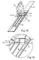
- Fig. 17 shows a schematic perspective view of another embodiment of the Rekonturiersystems 20, which is arranged on a workpiece 38.
- the workpiece 38 shown is a blade of a turbine.
- Fig. 17 is described below in synopsis with FIGS. 18 and 19 be explained, wherein Fig. 18 a schematic sectional view of in Fig. 17 shown arrangement of the Rekonturiersystems 20 on the workpiece 38 and Fig. 19 an enlarged view of the in Fig. 18 Show details shown XIX.
- the Rekonturiersystem 20 and its holding device 18 in the embodiment shown a plurality of clamping screws 46, by means of which arranged in the holding device 18 sacrificial element 28 is releasably fixed to the holding device 18.
Landscapes
- Engineering & Computer Science (AREA)
- Manufacturing & Machinery (AREA)
- Mechanical Engineering (AREA)
- Electrical Discharge Machining, Electrochemical Machining, And Combined Machining (AREA)
Priority Applications (1)
| Application Number | Priority Date | Filing Date | Title |
|---|---|---|---|
| EP12190783.6A EP2727677A1 (fr) | 2012-10-31 | 2012-10-31 | Procédé pour dresser au moins une électrode d'érosion et système de dressage |
Applications Claiming Priority (1)
| Application Number | Priority Date | Filing Date | Title |
|---|---|---|---|
| EP12190783.6A EP2727677A1 (fr) | 2012-10-31 | 2012-10-31 | Procédé pour dresser au moins une électrode d'érosion et système de dressage |
Publications (1)
| Publication Number | Publication Date |
|---|---|
| EP2727677A1 true EP2727677A1 (fr) | 2014-05-07 |
Family
ID=47172438
Family Applications (1)
| Application Number | Title | Priority Date | Filing Date |
|---|---|---|---|
| EP12190783.6A Withdrawn EP2727677A1 (fr) | 2012-10-31 | 2012-10-31 | Procédé pour dresser au moins une électrode d'érosion et système de dressage |
Country Status (1)
| Country | Link |
|---|---|
| EP (1) | EP2727677A1 (fr) |
Citations (5)
| Publication number | Priority date | Publication date | Assignee | Title |
|---|---|---|---|---|
| JPS547699A (en) * | 1977-06-20 | 1979-01-20 | Hitachi Ltd | Method of dressing wire-out electric-discharge processing electrodes |
| WO1988003452A1 (fr) * | 1986-03-11 | 1988-05-19 | Extrude Hone Corporation | Usinage a decharge electrique par rectification d'electrodes |
| JPH0230431A (ja) * | 1988-07-18 | 1990-01-31 | Hoden Seimitsu Kako Kenkyusho Ltd | 放電加工用電源装置 |
| EP1779952A2 (fr) * | 2005-10-27 | 2007-05-02 | United Technologies Corporation | Gabarit pour rectifier des électrodes. |
| EP1808251A1 (fr) * | 2006-01-16 | 2007-07-18 | Siemens Aktiengesellschaft | Procédé de dressage d'un électrode d'érosion et procédé d'usinage par électro-érosion |
-
2012
- 2012-10-31 EP EP12190783.6A patent/EP2727677A1/fr not_active Withdrawn
Patent Citations (5)
| Publication number | Priority date | Publication date | Assignee | Title |
|---|---|---|---|---|
| JPS547699A (en) * | 1977-06-20 | 1979-01-20 | Hitachi Ltd | Method of dressing wire-out electric-discharge processing electrodes |
| WO1988003452A1 (fr) * | 1986-03-11 | 1988-05-19 | Extrude Hone Corporation | Usinage a decharge electrique par rectification d'electrodes |
| JPH0230431A (ja) * | 1988-07-18 | 1990-01-31 | Hoden Seimitsu Kako Kenkyusho Ltd | 放電加工用電源装置 |
| EP1779952A2 (fr) * | 2005-10-27 | 2007-05-02 | United Technologies Corporation | Gabarit pour rectifier des électrodes. |
| EP1808251A1 (fr) * | 2006-01-16 | 2007-07-18 | Siemens Aktiengesellschaft | Procédé de dressage d'un électrode d'érosion et procédé d'usinage par électro-érosion |
Similar Documents
| Publication | Publication Date | Title |
|---|---|---|
| EP2181792B1 (fr) | Dispositif et procédé destinés à la fabrication de forages dans l'angle d'une aube de turbine | |
| EP2623246B1 (fr) | Électrode et installation destinés au traitement électrochimique ainsi que le procédé à cet effet | |
| DE102013108604A1 (de) | Vorrichtung und Verfahren zum Erzeugen von Mikrostrukturen in zylindrischen Oberflächen | |
| EP1837113A1 (fr) | Agencement d'électrode et procédé pour usiner par électro-érosion des materiaux électriquement non-conducteur | |
| DE1237713B (de) | Verfahren und Vorrichtung zur Metallbearbeitung mittels Elektro-Erosion | |
| DE102010032326A1 (de) | Elektrode und Verfahren zum elektrochemischen Bearbeiten eines Bauteils | |
| EP2237912B1 (fr) | Lame pour l'usinage d'électrodes de soudage par points, outil de fraisage et fraise à capot | |
| DE102004054587B3 (de) | Verfahren zum Herstellen von reproduzierbaren Mikrobohrungen sowie Vorrichtung dafür | |
| EP3281728A1 (fr) | Procédé de fabrication d'un composant d'une machine rotative et composant fabriqué selon un tel procédé | |
| DE102007000516A1 (de) | Hitzeschutzschild für eine Turbomaschine | |
| EP2727677A1 (fr) | Procédé pour dresser au moins une électrode d'érosion et système de dressage | |
| DE102008004776A1 (de) | Verfahren zur Herstellung von integral beschaufelten Rotoren | |
| DE10343760B4 (de) | Verfahren zur Herstellung oder Reparatur eines beschaufelten Rotors für eine Strömungsmaschine sowie dafür geeignete Schaufeln bzw. Ersatzschaufelabschnitte | |
| DE102015015162A1 (de) | Fluiddynamisches Lager | |
| EP1518631B1 (fr) | Méthode pour le reformage et/ou l'enlèvement de dépôts, en particulier pour les électrodes de soudage par résistance. | |
| DE102015216844A1 (de) | Vorrichtung und Verfahren zur Herstellung eines Schaufelblattes | |
| DE10319020A1 (de) | Verfahren und Vorrichtung zum Verrunden von Kanten an Bauteilen | |
| DE202017007570U1 (de) | Vorrichtung zur Herstellung von Zügen in Läufen von Feuerwaffen | |
| EP3291939A1 (fr) | Érosion de la denture intérieure sur des extrudeuses planétaires | |
| DE102006034116A1 (de) | Verfahren und Vorrichtung zur elektrochemischen Verarbeitung | |
| EP4045219A1 (fr) | Procédé et électrode pour usiner des pièces par usinage électrochimique | |
| DE102007062559A1 (de) | Verfahren zur Herstellung und Reparatur eines Bauteils und Bauteil einer Gasturbine | |
| EP3608047A1 (fr) | Procédé d'alésage dans des matériaux difficiles à usiner par enlèvement de copeaux | |
| EP1655091A1 (fr) | Méthode pour l'usinage par électrochimie d'une pièce et pièce de travail ayant un passage. | |
| EP1808251B1 (fr) | Procédé de dressage d'un électrode d'érosion et d'usinage par électro-érosion |
Legal Events
| Date | Code | Title | Description |
|---|---|---|---|
| PUAI | Public reference made under article 153(3) epc to a published international application that has entered the european phase |
Free format text: ORIGINAL CODE: 0009012 |
|
| 17P | Request for examination filed |
Effective date: 20121031 |
|
| AK | Designated contracting states |
Kind code of ref document: A1 Designated state(s): AL AT BE BG CH CY CZ DE DK EE ES FI FR GB GR HR HU IE IS IT LI LT LU LV MC MK MT NL NO PL PT RO RS SE SI SK SM TR |
|
| AX | Request for extension of the european patent |
Extension state: BA ME |
|
| RAP1 | Party data changed (applicant data changed or rights of an application transferred) |
Owner name: MTU AERO ENGINES GMBH |
|
| 17P | Request for examination filed |
Effective date: 20141008 |
|
| RBV | Designated contracting states (corrected) |
Designated state(s): AL AT BE BG CH CY CZ DE DK EE ES FI FR GB GR HR HU IE IS IT LI LT LU LV MC MK MT NL NO PL PT RO RS SE SI SK SM TR |
|
| RAP1 | Party data changed (applicant data changed or rights of an application transferred) |
Owner name: MTU AERO ENGINES AG |
|
| 17Q | First examination report despatched |
Effective date: 20161107 |
|
| STAA | Information on the status of an ep patent application or granted ep patent |
Free format text: STATUS: THE APPLICATION IS DEEMED TO BE WITHDRAWN |
|
| 18D | Application deemed to be withdrawn |
Effective date: 20170318 |