EP2726781B1 - Light guide - Google Patents
Light guide Download PDFInfo
- Publication number
- EP2726781B1 EP2726781B1 EP12742952.0A EP12742952A EP2726781B1 EP 2726781 B1 EP2726781 B1 EP 2726781B1 EP 12742952 A EP12742952 A EP 12742952A EP 2726781 B1 EP2726781 B1 EP 2726781B1
- Authority
- EP
- European Patent Office
- Prior art keywords
- light
- luminaire
- light source
- light guide
- cone part
- Prior art date
- Legal status (The legal status is an assumption and is not a legal conclusion. Google has not performed a legal analysis and makes no representation as to the accuracy of the status listed.)
- Active
Links
Images

Classifications
-
- F—MECHANICAL ENGINEERING; LIGHTING; HEATING; WEAPONS; BLASTING
- F21—LIGHTING
- F21V—FUNCTIONAL FEATURES OR DETAILS OF LIGHTING DEVICES OR SYSTEMS THEREOF; STRUCTURAL COMBINATIONS OF LIGHTING DEVICES WITH OTHER ARTICLES, NOT OTHERWISE PROVIDED FOR
- F21V7/00—Reflectors for light sources
- F21V7/04—Optical design
- F21V7/041—Optical design with conical or pyramidal surface
-
- F—MECHANICAL ENGINEERING; LIGHTING; HEATING; WEAPONS; BLASTING
- F21—LIGHTING
- F21V—FUNCTIONAL FEATURES OR DETAILS OF LIGHTING DEVICES OR SYSTEMS THEREOF; STRUCTURAL COMBINATIONS OF LIGHTING DEVICES WITH OTHER ARTICLES, NOT OTHERWISE PROVIDED FOR
- F21V7/00—Reflectors for light sources
- F21V7/0025—Combination of two or more reflectors for a single light source
-
- F—MECHANICAL ENGINEERING; LIGHTING; HEATING; WEAPONS; BLASTING
- F21—LIGHTING
- F21Y—INDEXING SCHEME ASSOCIATED WITH SUBCLASSES F21K, F21L, F21S and F21V, RELATING TO THE FORM OR THE KIND OF THE LIGHT SOURCES OR OF THE COLOUR OF THE LIGHT EMITTED
- F21Y2115/00—Light-generating elements of semiconductor light sources
- F21Y2115/10—Light-emitting diodes [LED]
Definitions
- the present invention relates to the field of light sources, and more specifically to a light guide.
- LEDs Light Emitting Diodes
- modules comprising LEDs
- a LED light source is also often located at the bottom of a reflector. This makes it necessary to develop reflectors designed specifically for such LED light sources which can be cost and capacity demanding. Furthermore, standard LED light source applications often suffer from glare.
- FR 2 639 683 A1 discloses a prior art light projector comprising a light source and a reflector.
- the light source comprises a number of light emitting diodes arranged in a ring centered on the optical axis of the projector.
- the projector further comprises a light diffuser in the form of a transparent hollow cone.
- US 2010/254128 A1 discloses a prior art reflector system for a lighting device. Two reflective surfaces are used to redirect the light before it is emitted.
- the light source is disposed at the base of a secondary reflector.
- a primary reflector which is arranged proximate to the light source initially redirects light from the light source such that the different wavelengths of the light are mixed as they are redirected toward the secondary reflector.
- the secondary reflector functions primarily to shape the light into a desired output beam.
- US 6 758 582 B1 discloses a lighting device including a concave mirror and a convex mirror.
- the convex mirror faces the concave mirror and is fixed to the same.
- a LED array is fixed to the concave mirror and faces the convex mirror such that light emitted by the LED array is reflected off of the convex mirror onto the concave mirror, and then reflected by the concave mirror to exit the lighting device.
- a luminaire comprising a light source comprising at least one light emitting diode and a mix box.
- the luminaire further comprising a light guide for guiding light emitted in a first direction from the light source comprising at least one light emitting diode, wherein the light guide is arranged to direct a major part of the light in a second direction, wherein the first direction is not equal to the second direction, wherein the light guide comprises a cone part having a shape of a cone, wherein a center axis of the cone part is in the first direction, and wherein the cone part has a circumferential surface.
- the luminaire comprises a light source comprising at least one light emitting diode (LED). This is advantageous in that it is capacity and cost efficient.
- the light emitted from the light source may be arranged to be reflected on the circumferential surface of the cone part such that after the reflection, the light is directed in the second direction.
- the circumferential surface may comprise a reflective coating. This is advantageous in that light incident on the circumferential surface that is not reflected by total internal reflection (because the angle of incidence is to small) is reflected.
- the reflective coating may be at least one from the group of a specularly reflective, and diffusively reflective. This is advantageous in that the distribution of the light can be made more uniform in terms of brightness.
- the circumferential surface may be at least one from the group of segmented and facetted. This is advantageous in that the distribution of the light can be made more uniform in terms of brightness.
- the light guide may be arranged to direct a minor part of the light in the first direction. This is advantageous in that there is less loss due to reflection.
- a center of the cone part may comprise a through opening such that light emitted from the light source directed to the center of the cone part continues through the cone part in the first direction. This is advantageous in that there is less loss due to reflection.
- the cone part may be arranged in a cylinder part in the shape of a cylinder.
- the cylinder part may be arranged to provide total internal reflection. This is advantageous in that there is less loss due to reflection.
- the luminaire may comprise a LED lighting module comprising at least one light emitting diode or an array of light emitting diodes.
- a LED lighting module comprising at least one light emitting diode or an array of light emitting diodes.
- An example of such a LED lighting module are the LED lighting modules being standardized within the standardizing consortium Zhaga.
- the light source may further comprise a diffusive exit window. This is advantageous in that properties of the light emitted from the light source can be adjusted.
- the luminaire may further comprise a reflector wherein the reflector is adapted for a light source selected from the group of high intensity discharge lamps and halogen lamps.
- the light guide may be used with reflectors that are adapted for light sources selected from the group of high intensity discharge lamps and halogen lamps which is both capacity and cost efficient.
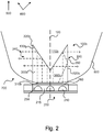
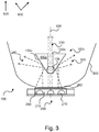
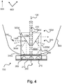
- Figs. 1-4 are schematic illustrations of cross-sections of embodiments of the inventive light guide arranged in an embodiment of the inventive luminaire. Firstly, the features in common will be described jointly with reference to Figs. 1-4 . Secondly, the differences will be described. When referring to, e.g., all embodiments of the light guide, a generic reference, such as 100 will be used. When referring to specific embodiments, specific references, such as, e.g., 100bd will be used.
- a luminaire 700 comprising a light guide 100, a light source 200 and a reflector 800.
- the reflector 800 may be adapted for a light source selected from the group of high intensity discharge lamps and halogen lamps.
- the reflector 800 may originally be manufactured for use with high intensity discharge lamps or halogen lamps but due to the light guide 100, the reflector 800 can be used together with a light source 200 in the form of at least one light emitting diode 210.
- the light source 200 comprises a light emitting diode module 215 comprising the at least one light emitting diode 210.
- a diffusive window 260 is arranged in the light source 200 such that light emitted from the at least one light emitting diode 210 travels through the diffusive window 260.
- the diffusive window 260 is arranged to spread the light that travels through it which results in more uniform brightness of the light emitted from the light source 200.
- the light source 200 also comprises a mix box 250 arranged to mix the light emitted from the light source 200.
- a mix box is a space surrounded by reflective walls, in which light is reflected multiple times.
- the diffusive window 260 is arranged in front of the mix box 250 and be covered by a diffusive cover.
- the light guide 100 has a cone part 110 having a shape of a cone.
- a center axis 120 of the cone part 110 is in a first direction 500.
- Light from the light source 200 is emitted in a semispherical distribution, which is oriented in the first direction 500.
- the light guide 100 is arranged to direct a major part of the light 240 in a second direction 600, wherein the first direction 500 is not equal to the second direction 600.
- the second direction 600 is herein to be interpreted broadly.
- the second direction 600 can be any direction that is not parallel to the first direction 500.
- the cone part 110 has a circumferential surface 130.
- the light emitted from the light source 200 is arranged to be reflected on the circumferential surface 130 of the cone part 110 such that after the reflection, the light is directed in the second direction 600.
- the circumferential surface 130 may comprise a reflective coating.
- the reflective coating may be at least one from the group of a specularly reflective, and diffusively reflective.
- the reflective coating can be any type known to the skilled person, e.g., a metallic coating.
- the circumferential surface 130 may be at least one from the group of segmented and facetted. This is to be interpreted as that the circumferential surface may be embodied having all sorts of embodiments comprising amounts of facets and/or segments ranging from 0 to infinity. Facets may be distributed along segments. Alternatively, facets may be distributed randomly. The facets and/or segments may be flat. Alternatively, the facets and/or segments may have a corrugated surface.
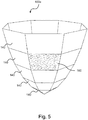
- Fig. 5 discloses an embodiment of a light guide. It is to be understood that the features of the light guide 100e are applicable also to the light guides 100abcd.
- the circumferential surface of the light guide 100e comprises facets and segments.
- the facets 140 form a segment.
- the facet 160 has a corrugated surface. It is to be noted that the light guides may be embodied having facets but no segments.
- the light guides 100ac in Figs. 1 and 3 have, as previously discussed, cone parts 110ac. These cone parts 110ac can, e.g., be attached to the reflector 800 or to a housing (not shown) of the luminaire 700. Methods can be used that are known to those skilled in the art of fitting optical elements in front of a light source. For instance, a steel bracket can be used.
- the light guides 100cd of Figs. 3-4 comprise, in the center part of the cone part 110cd, a through opening 140cd such that light emitted from the light source 200 directed to the center of the cone part 110cd continues through the cone part 110cd in the first direction 500.
- the light guides 100cd are arranged to direct a minor part of the light 230 in the first direction 500.
- the light guides 100bd comprise cylinder parts 300bd in the shape of a cylinder.
- the cylinder parts 300bd provide total internal reflection. Total internal reflection is to be interpreted as that light reflected internally in the cylinder parts 300bd is reflected solely due to difference in refractive index between the light guide and the surrounding air, resulting in reflection without loss.
- Light emitted from the light source 200 enters the light guide 100bd through a base 310bd of the cylinder part 300bd.
- Light that is incident on the side walls 320bd in a direction close to the surface normal continues through the side walls 320bd towards the reflector 800.
- Light that is incident on the side walls 320bd at a large angle in relation to the surface normal is reflected (see, e.g., light ray 250. The larger the angle of incidence in relation to the surface normal, the more light is reflected.
- the height at which the light from the light guide 100 reaches the reflector 800 is determined by the height of the cone part 110. This can be varied by either varying the height at which the cylinder part 110ac is attached, or by varying the height of the cylinder part 300bd.
- the angle at which the light is emitted from the light guide 100ac is determined by the top angle 135 of the cone part 110ac.
- the disclosed embodiments relate to a light guide 100a and a luminaire 700 including such a light guide 100a.
- the light guide 100a guides light emitted in a first direction 500 from a light source 200 comprising at least one light emitting diode 210.
- the light guide 100 directs a major part of the light in a second direction 600, wherein the first direction 500 is not equal to the second direction 600.
- the light guide 100a comprises a cone part 110a having a shape of a cone, and a center axis 120 of the cone part 110a is in the first direction 500.
- the light guide 100a can be used with reflectors 800 that have originally been manufactured for use with high intensity discharge lamps or halogen lamps but because of the light guide 100a, the reflectors 800 can be used together with light sources 200 in the form of at least one light emitting diode 210.
Description
- The present invention relates to the field of light sources, and more specifically to a light guide.
- LEDs (Light Emitting Diodes) or modules comprising LEDs, generate light in the form of a half sphere instead of the omnidirectional light pattern emitted by other present art light sources like HID (High Intensity Discharge) lamps and halogen lamps. A LED light source is also often located at the bottom of a reflector. This makes it necessary to develop reflectors designed specifically for such LED light sources which can be cost and capacity demanding. Furthermore, standard LED light source applications often suffer from glare.
-
FR 2 639 683 A1 -
US 2010/254128 A1 discloses a prior art reflector system for a lighting device. Two reflective surfaces are used to redirect the light before it is emitted. The light source is disposed at the base of a secondary reflector. A primary reflector which is arranged proximate to the light source initially redirects light from the light source such that the different wavelengths of the light are mixed as they are redirected toward the secondary reflector. The secondary reflector functions primarily to shape the light into a desired output beam. -
US 6 758 582 B1 discloses a lighting device including a concave mirror and a convex mirror. The convex mirror faces the concave mirror and is fixed to the same. A LED array is fixed to the concave mirror and faces the convex mirror such that light emitted by the LED array is reflected off of the convex mirror onto the concave mirror, and then reflected by the concave mirror to exit the lighting device. - It is an object of the present invention to overcome or alleviate problems of the prior art.
- According to a first aspect of the invention, this and other objects are achieved by a luminaire comprising a light source comprising at least one light emitting diode and a mix box. The luminaire further comprising a light guide for guiding light emitted in a first direction from the light source comprising at least one light emitting diode, wherein the light guide is arranged to direct a major part of the light in a second direction, wherein the first direction is not equal to the second direction, wherein the light guide comprises a cone part having a shape of a cone, wherein a center axis of the cone part is in the first direction, and wherein the cone part has a circumferential surface. This is advantageous in that glare is limited since a major part of the light leaves the cone part in the second direction and thus less light comes directly from the light source. Furthermore, because the light travels through the light guide, the light will be mixed to some extent, enabling a more homogeneous beam pattern. As mentioned the luminaire comprises a light source comprising at least one light emitting diode (LED). This is advantageous in that it is capacity and cost efficient.
- The light emitted from the light source may be arranged to be reflected on the circumferential surface of the cone part such that after the reflection, the light is directed in the second direction.
- The circumferential surface may comprise a reflective coating. This is advantageous in that light incident on the circumferential surface that is not reflected by total internal reflection (because the angle of incidence is to small) is reflected.
- The reflective coating may be at least one from the group of a specularly reflective, and diffusively reflective. This is advantageous in that the distribution of the light can be made more uniform in terms of brightness.
- The circumferential surface may be at least one from the group of segmented and facetted. This is advantageous in that the distribution of the light can be made more uniform in terms of brightness.
- The light guide may be arranged to direct a minor part of the light in the first direction. This is advantageous in that there is less loss due to reflection.
- A center of the cone part may comprise a through opening such that light emitted from the light source directed to the center of the cone part continues through the cone part in the first direction. This is advantageous in that there is less loss due to reflection.
- The cone part may be arranged in a cylinder part in the shape of a cylinder.
- The cylinder part may be arranged to provide total internal reflection. This is advantageous in that there is less loss due to reflection.
- Alternatively, the luminaire may comprise a LED lighting module comprising at least one light emitting diode or an array of light emitting diodes. An example of such a LED lighting module are the LED lighting modules being standardized within the standardizing consortium Zhaga.
- The light source may further comprise a diffusive exit window. This is advantageous in that properties of the light emitted from the light source can be adjusted.
- The luminaire may further comprise a reflector wherein the reflector is adapted for a light source selected from the group of high intensity discharge lamps and halogen lamps. This is advantageous in that the light guide may be used with reflectors that are adapted for light sources selected from the group of high intensity discharge lamps and halogen lamps which is both capacity and cost efficient.
- It is noted that the invention relates to all possible combinations of features recited in the claims.
- This and other aspects of the present invention will now be described in more detail, with reference to the appended drawings showing embodiments of the invention in which,
-
Fig. 1 is a schematic illustration of a cross-section of an embodiment of the inventive light guide arranged in an embodiment of the inventive luminaire. -
Fig. 2 is a schematic illustration of a cross-section of an embodiment of the inventive light guide arranged in an embodiment of the inventive luminaire. -
Fig. 3 is a schematic illustration of a cross-section of an embodiment of the inventive light guide arranged in an embodiment of the inventive luminaire. -
Fig. 4 is a schematic illustration of a cross-section of an embodiment of the inventive light guide arranged in an embodiment of the inventive luminaire. -
Fig. 5 is a schematic illustration of a perspective view of an embodiment of the inventive light guide. -
Figs. 1-4 are schematic illustrations of cross-sections of embodiments of the inventive light guide arranged in an embodiment of the inventive luminaire. Firstly, the features in common will be described jointly with reference toFigs. 1-4 . Secondly, the differences will be described. When referring to, e.g., all embodiments of the light guide, a generic reference, such as 100 will be used. When referring to specific embodiments, specific references, such as, e.g., 100bd will be used. - A luminaire 700 is disclosed comprising a light guide 100, a
light source 200 and areflector 800. Thereflector 800 may be adapted for a light source selected from the group of high intensity discharge lamps and halogen lamps. Thus, thereflector 800 may originally be manufactured for use with high intensity discharge lamps or halogen lamps but due to the light guide 100, thereflector 800 can be used together with alight source 200 in the form of at least onelight emitting diode 210. - The
light source 200 comprises a lightemitting diode module 215 comprising the at least onelight emitting diode 210. Adiffusive window 260 is arranged in thelight source 200 such that light emitted from the at least onelight emitting diode 210 travels through thediffusive window 260. Thediffusive window 260 is arranged to spread the light that travels through it which results in more uniform brightness of the light emitted from thelight source 200. Thelight source 200 also comprises amix box 250 arranged to mix the light emitted from thelight source 200. A mix box is a space surrounded by reflective walls, in which light is reflected multiple times. Due to the multiple reflections, the light can be seen as to originate from any point within this space, thus creating the effect of a single (larger) light source, instead of multiple (small) light sources. Thediffusive window 260 is arranged in front of themix box 250 and be covered by a diffusive cover. - The light guide 100 has a cone part 110 having a shape of a cone. A
center axis 120 of the cone part 110 is in afirst direction 500. - Light from the
light source 200 is emitted in a semispherical distribution, which is oriented in thefirst direction 500. The light guide 100 is arranged to direct a major part of the light 240 in asecond direction 600, wherein thefirst direction 500 is not equal to thesecond direction 600. It is to be noted that thesecond direction 600 is herein to be interpreted broadly. Thesecond direction 600 can be any direction that is not parallel to thefirst direction 500. - The cone part 110 has a circumferential surface 130. The light emitted from the
light source 200 is arranged to be reflected on the circumferential surface 130 of the cone part 110 such that after the reflection, the light is directed in thesecond direction 600. - The circumferential surface 130 may comprise a reflective coating. The reflective coating may be at least one from the group of a specularly reflective, and diffusively reflective. The reflective coating can be any type known to the skilled person, e.g., a metallic coating.
- The circumferential surface 130 may be at least one from the group of segmented and facetted. This is to be interpreted as that the circumferential surface may be embodied having all sorts of embodiments comprising amounts of facets and/or segments ranging from 0 to infinity. Facets may be distributed along segments. Alternatively, facets may be distributed randomly. The facets and/or segments may be flat. Alternatively, the facets and/or segments may have a corrugated surface.
-
Fig. 5 discloses an embodiment of a light guide. It is to be understood that the features of thelight guide 100e are applicable also to the light guides 100abcd. The circumferential surface of thelight guide 100e comprises facets and segments. Thefacets 140 form a segment. Thefacet 160 has a corrugated surface. It is to be noted that the light guides may be embodied having facets but no segments. - The light guides 100ac in
Figs. 1 and3 have, as previously discussed, cone parts 110ac. These cone parts 110ac can, e.g., be attached to thereflector 800 or to a housing (not shown) of theluminaire 700. Methods can be used that are known to those skilled in the art of fitting optical elements in front of a light source. For instance, a steel bracket can be used. - The light guides 100cd of
Figs. 3-4 comprise, in the center part of the cone part 110cd, a through opening 140cd such that light emitted from thelight source 200 directed to the center of the cone part 110cd continues through the cone part 110cd in thefirst direction 500. Thus, the light guides 100cd are arranged to direct a minor part of the light 230 in thefirst direction 500. - In
Figs. 2 and4 , the light guides 100bd comprise cylinder parts 300bd in the shape of a cylinder. Preferably, the cylinder parts 300bd provide total internal reflection. Total internal reflection is to be interpreted as that light reflected internally in the cylinder parts 300bd is reflected solely due to difference in refractive index between the light guide and the surrounding air, resulting in reflection without loss. Light emitted from thelight source 200 enters the light guide 100bd through a base 310bd of the cylinder part 300bd. Light that is incident on the side walls 320bd in a direction close to the surface normal continues through the side walls 320bd towards thereflector 800. Light that is incident on the side walls 320bd at a large angle in relation to the surface normal is reflected (see, e.g.,light ray 250. The larger the angle of incidence in relation to the surface normal, the more light is reflected. - The height at which the light from the light guide 100 reaches the
reflector 800 is determined by the height of the cone part 110. This can be varied by either varying the height at which the cylinder part 110ac is attached, or by varying the height of the cylinder part 300bd. - The angle at which the light is emitted from the light guide 100ac is determined by the
top angle 135 of the cone part 110ac. - In summary, the disclosed embodiments relate to a
light guide 100a and aluminaire 700 including such alight guide 100a. Thelight guide 100a guides light emitted in afirst direction 500 from alight source 200 comprising at least onelight emitting diode 210. The light guide 100 directs a major part of the light in asecond direction 600, wherein thefirst direction 500 is not equal to thesecond direction 600. Thelight guide 100a comprises acone part 110a having a shape of a cone, and acenter axis 120 of thecone part 110a is in thefirst direction 500. Thelight guide 100a can be used withreflectors 800 that have originally been manufactured for use with high intensity discharge lamps or halogen lamps but because of thelight guide 100a, thereflectors 800 can be used together withlight sources 200 in the form of at least onelight emitting diode 210. - While the invention has been illustrated and described in detail in the drawings and foregoing description, such illustration and description are to be considered illustrative or exemplary and not restrictive; the invention is not limited to the disclosed embodiments.
Claims (10)
- A luminaire (700) comprising a light source (200) comprising at least one light emitting diode (200), the luminaire (700) further comprising a light guide (100) for guiding light emitted in a first direction (500) from the light source (200),
wherein the light guide (100) is arranged to direct a major part of the light in a second direction (600), wherein the first direction (500) is not equal to the second direction (600),
wherein the light guide (100) comprises a cone part (110) having a shape of a cone, wherein a center axis (120) of the cone part (110) is in the first direction (500), and wherein the cone part (110) has a circumferential surface (130),
wherein the light source (200) further comprising a mix box (250),
characterised by
a diffusive exit window (260) arranged in front of the mix box (250), wherein light emitted from the light source (200) enters the light guide (100) through a base (310). - A luminaire (700) according to claim 1, wherein the light emitted from the light source (200) is arranged to be reflected on the circumferential surface (130) of the cone part (110) such that after the reflection, the light is directed in the second direction (600).
- A luminaire (700) according to anyone of claims 1-2, wherein the circumferential surface (130) comprises a reflective coating.
- A luminaire (700) according to claim 3, wherein the reflective coating is at least one from the group of a specularly reflective, and diffusively reflective.
- A luminaire (700) according to anyone of claims 1-4, wherein the circumferential surface (130) is at least one from the group of segmented and facetted.
- A luminaire (700) according to anyone of claims 1-5, wherein the light guide (100cd) is arranged to direct a minor part of the light (230) in the first direction (500).
- A luminaire (700) according to anyone of claims 1-6, wherein a center of the cone part (110cd) comprises a through opening (140cd) such that light emitted from the light source (200) directed to the center of the cone part (110cd) continues through the cone part (110cd) in the first direction (500).
- A luminaire (700) according to anyone of claims 1-7, wherein the cone part (110bd) is arranged in a cylinder part (300bd) in the shape of a cylinder.
- A luminaire (700) according to claim 8, wherein the cylinder part (300bd) is arranged to provide total internal reflection.
- Luminaire (700) according to anyone of claims 1-9, further comprising a reflector (800) wherein the reflector (800) is adapted for a light source selected from the group of high intensity discharge lamps and halogen lamps.
Priority Applications (1)
| Application Number | Priority Date | Filing Date | Title |
|---|---|---|---|
| EP12742952.0A EP2726781B1 (en) | 2011-07-01 | 2012-06-28 | Light guide |
Applications Claiming Priority (3)
| Application Number | Priority Date | Filing Date | Title |
|---|---|---|---|
| EP11172400 | 2011-07-01 | ||
| PCT/IB2012/053273 WO2013005142A1 (en) | 2011-07-01 | 2012-06-28 | Light guide |
| EP12742952.0A EP2726781B1 (en) | 2011-07-01 | 2012-06-28 | Light guide |
Publications (2)
| Publication Number | Publication Date |
|---|---|
| EP2726781A1 EP2726781A1 (en) | 2014-05-07 |
| EP2726781B1 true EP2726781B1 (en) | 2019-08-07 |
Family
ID=46604012
Family Applications (1)
| Application Number | Title | Priority Date | Filing Date |
|---|---|---|---|
| EP12742952.0A Active EP2726781B1 (en) | 2011-07-01 | 2012-06-28 | Light guide |
Country Status (5)
| Country | Link |
|---|---|
| US (1) | US20140126216A1 (en) |
| EP (1) | EP2726781B1 (en) |
| JP (1) | JP6118317B2 (en) |
| CN (1) | CN103649630A (en) |
| WO (1) | WO2013005142A1 (en) |
Families Citing this family (7)
| Publication number | Priority date | Publication date | Assignee | Title |
|---|---|---|---|---|
| BR112015032298A2 (en) * | 2013-06-27 | 2017-07-25 | Koninklijke Philips Nv | lighting device |
| CN104344351A (en) * | 2013-07-23 | 2015-02-11 | 富优技研股份有限公司 | Manufacturing method for light guide column |
| US9279548B1 (en) | 2014-08-18 | 2016-03-08 | 3M Innovative Properties Company | Light collimating assembly with dual horns |
| JP6475953B2 (en) * | 2014-11-10 | 2019-02-27 | スタンレー電気株式会社 | Lighting device |
| CN104976555B (en) * | 2014-12-31 | 2017-11-21 | 苏州东善微光光电技术有限公司 | A kind of plant illumination device and method |
| JP6563772B2 (en) * | 2015-10-20 | 2019-08-21 | 信号電材株式会社 | lighting equipment |
| DE102016204697A1 (en) * | 2016-03-22 | 2017-09-28 | Osram Gmbh | Retrofit lamp and vehicle headlight with retrofit lamp |
Family Cites Families (17)
| Publication number | Priority date | Publication date | Assignee | Title |
|---|---|---|---|---|
| DE2133719C3 (en) * | 1971-07-07 | 1978-08-24 | Original Hanau Quarzlampen Gmbh, 6450 Hanau | Operating light |
| US4037096A (en) * | 1974-08-09 | 1977-07-19 | American Sterilizer Company | Illuminator apparatus using optical reflective methods |
| FR2639683B1 (en) * | 1988-11-28 | 1991-03-08 | Autorupteur Cie Nle | LIGHT PROJECTOR |
| US5535111A (en) * | 1994-04-29 | 1996-07-09 | Thomas & Betts Corporation | Quartz halogen flood light assembly having improved lamp and reflector |
| TWI240788B (en) * | 2000-05-04 | 2005-10-01 | Koninkl Philips Electronics Nv | Illumination system, light mixing chamber and display device |
| JP2002075025A (en) * | 2000-08-25 | 2002-03-15 | Stanley Electric Co Ltd | Led lighting fixture for vehicle |
| JP4816707B2 (en) * | 2002-03-20 | 2011-11-16 | 豊田合成株式会社 | Light emitter and automobile backlight |
| FR2846400B1 (en) * | 2002-10-28 | 2005-10-07 | Valeo Vision | SIGNALING LIGHT COMPRISING A DEVICE FOR RECOVERING AND DISTRIBUTING THE LUMINOUS FLOW TO AN ANNULAR REFLECTOR |
| US6758582B1 (en) * | 2003-03-19 | 2004-07-06 | Elumina Technology Incorporation | LED lighting device |
| US7607808B2 (en) * | 2004-06-16 | 2009-10-27 | Continental Automotive Systems Us, Inc. | Instrument panel housing with light diffuser |
| KR100534590B1 (en) * | 2005-05-26 | 2005-12-08 | 서종범 | Input device and position recognition method using ultrasound |
| EP1952055B1 (en) * | 2005-11-17 | 2019-01-09 | Philips Lighting Holding B.V. | Lamp assembly |
| JP2007317431A (en) * | 2006-05-24 | 2007-12-06 | Ushio Inc | Lighting system |
| US9086213B2 (en) * | 2007-10-17 | 2015-07-21 | Xicato, Inc. | Illumination device with light emitting diodes |
| JP5022860B2 (en) * | 2007-10-23 | 2012-09-12 | パナソニック株式会社 | Lighting device for production |
| US7922366B2 (en) * | 2008-11-07 | 2011-04-12 | Chia-Mao Li | LED light source with light refractor and reflector |
| US8529102B2 (en) * | 2009-04-06 | 2013-09-10 | Cree, Inc. | Reflector system for lighting device |
-
2012
- 2012-06-28 JP JP2014518028A patent/JP6118317B2/en active Active
- 2012-06-28 CN CN201280032815.7A patent/CN103649630A/en active Pending
- 2012-06-28 US US14/129,360 patent/US20140126216A1/en not_active Abandoned
- 2012-06-28 WO PCT/IB2012/053273 patent/WO2013005142A1/en active Application Filing
- 2012-06-28 EP EP12742952.0A patent/EP2726781B1/en active Active
Non-Patent Citations (1)
| Title |
|---|
| None * |
Also Published As
| Publication number | Publication date |
|---|---|
| EP2726781A1 (en) | 2014-05-07 |
| US20140126216A1 (en) | 2014-05-08 |
| CN103649630A (en) | 2014-03-19 |
| JP6118317B2 (en) | 2017-04-19 |
| WO2013005142A1 (en) | 2013-01-10 |
| JP2014527258A (en) | 2014-10-09 |
Similar Documents
| Publication | Publication Date | Title |
|---|---|---|
| EP2726781B1 (en) | Light guide | |
| US7934858B2 (en) | Lighting lens and lighting device equipped with the same | |
| US11920780B2 (en) | Lens for improved color mixing and beam control of an LED light source | |
| US9157602B2 (en) | Optical element for a light source and lighting system using same | |
| US10415799B1 (en) | Dual output downlight fixture | |
| EP2726780B1 (en) | Light guide | |
| CN105556374A (en) | An optical system for producing uniform illumination | |
| EP2721656B1 (en) | Led light source | |
| US10520663B2 (en) | Illumination system based on active and passive illumination devices | |
| US8403538B2 (en) | Color homogenizing optical assembly | |
| JP5785551B2 (en) | Lighting equipment and optical components | |
| CA3061625C (en) | Total internal reflection lens to lessen glare and maintain color mixing and beam control | |
| JP6678524B2 (en) | Lighting equipment | |
| EP2843301A1 (en) | Light engine for an illumination device | |
| CN105953175A (en) | Projection lamp lens, light-emitting module with projection lamp lens and projection lamp | |
| CN116888402A (en) | Optical design for steerable reflective illuminator |
Legal Events
| Date | Code | Title | Description |
|---|---|---|---|
| PUAI | Public reference made under article 153(3) epc to a published international application that has entered the european phase |
Free format text: ORIGINAL CODE: 0009012 |
|
| 17P | Request for examination filed |
Effective date: 20140203 |
|
| AK | Designated contracting states |
Kind code of ref document: A1 Designated state(s): AL AT BE BG CH CY CZ DE DK EE ES FI FR GB GR HR HU IE IS IT LI LT LU LV MC MK MT NL NO PL PT RO RS SE SI SK SM TR |
|
| DAX | Request for extension of the european patent (deleted) | ||
| RAP1 | Party data changed (applicant data changed or rights of an application transferred) |
Owner name: PHILIPS LIGHTING HOLDING B.V. |
|
| RIN1 | Information on inventor provided before grant (corrected) |
Inventor name: VAN KEMPEN, FRANK WALTERUS FRANCISCUS MARIE Inventor name: VAN AS, MARCO Inventor name: KESER, MERIJN |
|
| STAA | Information on the status of an ep patent application or granted ep patent |
Free format text: STATUS: EXAMINATION IS IN PROGRESS |
|
| 17Q | First examination report despatched |
Effective date: 20180517 |
|
| RAP1 | Party data changed (applicant data changed or rights of an application transferred) |
Owner name: PHILIPS LIGHTING HOLDING B.V. |
|
| GRAP | Despatch of communication of intention to grant a patent |
Free format text: ORIGINAL CODE: EPIDOSNIGR1 |
|
| STAA | Information on the status of an ep patent application or granted ep patent |
Free format text: STATUS: GRANT OF PATENT IS INTENDED |
|
| RAP1 | Party data changed (applicant data changed or rights of an application transferred) |
Owner name: SIGNIFY HOLDING B.V. |
|
| INTG | Intention to grant announced |
Effective date: 20190220 |
|
| GRAS | Grant fee paid |
Free format text: ORIGINAL CODE: EPIDOSNIGR3 |
|
| GRAA | (expected) grant |
Free format text: ORIGINAL CODE: 0009210 |
|
| STAA | Information on the status of an ep patent application or granted ep patent |
Free format text: STATUS: THE PATENT HAS BEEN GRANTED |
|
| AK | Designated contracting states |
Kind code of ref document: B1 Designated state(s): AL AT BE BG CH CY CZ DE DK EE ES FI FR GB GR HR HU IE IS IT LI LT LU LV MC MK MT NL NO PL PT RO RS SE SI SK SM TR |
|
| REG | Reference to a national code |
Ref country code: GB Ref legal event code: FG4D |
|
| REG | Reference to a national code |
Ref country code: CH Ref legal event code: EP Ref country code: AT Ref legal event code: REF Ref document number: 1164437 Country of ref document: AT Kind code of ref document: T Effective date: 20190815 |
|
| REG | Reference to a national code |
Ref country code: DE Ref legal event code: R096 Ref document number: 602012062686 Country of ref document: DE |
|
| REG | Reference to a national code |
Ref country code: IE Ref legal event code: FG4D |
|
| REG | Reference to a national code |
Ref country code: NL Ref legal event code: MP Effective date: 20190807 |
|
| REG | Reference to a national code |
Ref country code: LT Ref legal event code: MG4D |
|
| PG25 | Lapsed in a contracting state [announced via postgrant information from national office to epo] |
Ref country code: BG Free format text: LAPSE BECAUSE OF FAILURE TO SUBMIT A TRANSLATION OF THE DESCRIPTION OR TO PAY THE FEE WITHIN THE PRESCRIBED TIME-LIMIT Effective date: 20191107 Ref country code: HR Free format text: LAPSE BECAUSE OF FAILURE TO SUBMIT A TRANSLATION OF THE DESCRIPTION OR TO PAY THE FEE WITHIN THE PRESCRIBED TIME-LIMIT Effective date: 20190807 Ref country code: NL Free format text: LAPSE BECAUSE OF FAILURE TO SUBMIT A TRANSLATION OF THE DESCRIPTION OR TO PAY THE FEE WITHIN THE PRESCRIBED TIME-LIMIT Effective date: 20190807 Ref country code: LT Free format text: LAPSE BECAUSE OF FAILURE TO SUBMIT A TRANSLATION OF THE DESCRIPTION OR TO PAY THE FEE WITHIN THE PRESCRIBED TIME-LIMIT Effective date: 20190807 Ref country code: NO Free format text: LAPSE BECAUSE OF FAILURE TO SUBMIT A TRANSLATION OF THE DESCRIPTION OR TO PAY THE FEE WITHIN THE PRESCRIBED TIME-LIMIT Effective date: 20191107 Ref country code: PT Free format text: LAPSE BECAUSE OF FAILURE TO SUBMIT A TRANSLATION OF THE DESCRIPTION OR TO PAY THE FEE WITHIN THE PRESCRIBED TIME-LIMIT Effective date: 20191209 Ref country code: FI Free format text: LAPSE BECAUSE OF FAILURE TO SUBMIT A TRANSLATION OF THE DESCRIPTION OR TO PAY THE FEE WITHIN THE PRESCRIBED TIME-LIMIT Effective date: 20190807 Ref country code: SE Free format text: LAPSE BECAUSE OF FAILURE TO SUBMIT A TRANSLATION OF THE DESCRIPTION OR TO PAY THE FEE WITHIN THE PRESCRIBED TIME-LIMIT Effective date: 20190807 |
|
| REG | Reference to a national code |
Ref country code: AT Ref legal event code: MK05 Ref document number: 1164437 Country of ref document: AT Kind code of ref document: T Effective date: 20190807 |
|
| PG25 | Lapsed in a contracting state [announced via postgrant information from national office to epo] |
Ref country code: GR Free format text: LAPSE BECAUSE OF FAILURE TO SUBMIT A TRANSLATION OF THE DESCRIPTION OR TO PAY THE FEE WITHIN THE PRESCRIBED TIME-LIMIT Effective date: 20191108 Ref country code: IS Free format text: LAPSE BECAUSE OF FAILURE TO SUBMIT A TRANSLATION OF THE DESCRIPTION OR TO PAY THE FEE WITHIN THE PRESCRIBED TIME-LIMIT Effective date: 20191207 Ref country code: RS Free format text: LAPSE BECAUSE OF FAILURE TO SUBMIT A TRANSLATION OF THE DESCRIPTION OR TO PAY THE FEE WITHIN THE PRESCRIBED TIME-LIMIT Effective date: 20190807 Ref country code: LV Free format text: LAPSE BECAUSE OF FAILURE TO SUBMIT A TRANSLATION OF THE DESCRIPTION OR TO PAY THE FEE WITHIN THE PRESCRIBED TIME-LIMIT Effective date: 20190807 Ref country code: AL Free format text: LAPSE BECAUSE OF FAILURE TO SUBMIT A TRANSLATION OF THE DESCRIPTION OR TO PAY THE FEE WITHIN THE PRESCRIBED TIME-LIMIT Effective date: 20190807 Ref country code: ES Free format text: LAPSE BECAUSE OF FAILURE TO SUBMIT A TRANSLATION OF THE DESCRIPTION OR TO PAY THE FEE WITHIN THE PRESCRIBED TIME-LIMIT Effective date: 20190807 |
|
| PG25 | Lapsed in a contracting state [announced via postgrant information from national office to epo] |
Ref country code: TR Free format text: LAPSE BECAUSE OF FAILURE TO SUBMIT A TRANSLATION OF THE DESCRIPTION OR TO PAY THE FEE WITHIN THE PRESCRIBED TIME-LIMIT Effective date: 20190807 |
|
| PG25 | Lapsed in a contracting state [announced via postgrant information from national office to epo] |
Ref country code: RO Free format text: LAPSE BECAUSE OF FAILURE TO SUBMIT A TRANSLATION OF THE DESCRIPTION OR TO PAY THE FEE WITHIN THE PRESCRIBED TIME-LIMIT Effective date: 20190807 Ref country code: IT Free format text: LAPSE BECAUSE OF FAILURE TO SUBMIT A TRANSLATION OF THE DESCRIPTION OR TO PAY THE FEE WITHIN THE PRESCRIBED TIME-LIMIT Effective date: 20190807 Ref country code: EE Free format text: LAPSE BECAUSE OF FAILURE TO SUBMIT A TRANSLATION OF THE DESCRIPTION OR TO PAY THE FEE WITHIN THE PRESCRIBED TIME-LIMIT Effective date: 20190807 Ref country code: DK Free format text: LAPSE BECAUSE OF FAILURE TO SUBMIT A TRANSLATION OF THE DESCRIPTION OR TO PAY THE FEE WITHIN THE PRESCRIBED TIME-LIMIT Effective date: 20190807 Ref country code: AT Free format text: LAPSE BECAUSE OF FAILURE TO SUBMIT A TRANSLATION OF THE DESCRIPTION OR TO PAY THE FEE WITHIN THE PRESCRIBED TIME-LIMIT Effective date: 20190807 Ref country code: PL Free format text: LAPSE BECAUSE OF FAILURE TO SUBMIT A TRANSLATION OF THE DESCRIPTION OR TO PAY THE FEE WITHIN THE PRESCRIBED TIME-LIMIT Effective date: 20190807 |
|
| PG25 | Lapsed in a contracting state [announced via postgrant information from national office to epo] |
Ref country code: CZ Free format text: LAPSE BECAUSE OF FAILURE TO SUBMIT A TRANSLATION OF THE DESCRIPTION OR TO PAY THE FEE WITHIN THE PRESCRIBED TIME-LIMIT Effective date: 20190807 Ref country code: SK Free format text: LAPSE BECAUSE OF FAILURE TO SUBMIT A TRANSLATION OF THE DESCRIPTION OR TO PAY THE FEE WITHIN THE PRESCRIBED TIME-LIMIT Effective date: 20190807 Ref country code: SM Free format text: LAPSE BECAUSE OF FAILURE TO SUBMIT A TRANSLATION OF THE DESCRIPTION OR TO PAY THE FEE WITHIN THE PRESCRIBED TIME-LIMIT Effective date: 20190807 Ref country code: IS Free format text: LAPSE BECAUSE OF FAILURE TO SUBMIT A TRANSLATION OF THE DESCRIPTION OR TO PAY THE FEE WITHIN THE PRESCRIBED TIME-LIMIT Effective date: 20200224 |
|
| REG | Reference to a national code |
Ref country code: DE Ref legal event code: R097 Ref document number: 602012062686 Country of ref document: DE |
|
| PLBE | No opposition filed within time limit |
Free format text: ORIGINAL CODE: 0009261 |
|
| STAA | Information on the status of an ep patent application or granted ep patent |
Free format text: STATUS: NO OPPOSITION FILED WITHIN TIME LIMIT |
|
| PG2D | Information on lapse in contracting state deleted |
Ref country code: IS |
|
| PGFP | Annual fee paid to national office [announced via postgrant information from national office to epo] |
Ref country code: FR Payment date: 20200626 Year of fee payment: 9 |
|
| 26N | No opposition filed |
Effective date: 20200603 |
|
| PG25 | Lapsed in a contracting state [announced via postgrant information from national office to epo] |
Ref country code: SI Free format text: LAPSE BECAUSE OF FAILURE TO SUBMIT A TRANSLATION OF THE DESCRIPTION OR TO PAY THE FEE WITHIN THE PRESCRIBED TIME-LIMIT Effective date: 20190807 |
|
| PGFP | Annual fee paid to national office [announced via postgrant information from national office to epo] |
Ref country code: GB Payment date: 20200630 Year of fee payment: 9 |
|
| PGFP | Annual fee paid to national office [announced via postgrant information from national office to epo] |
Ref country code: DE Payment date: 20200630 Year of fee payment: 9 |
|
| PG25 | Lapsed in a contracting state [announced via postgrant information from national office to epo] |
Ref country code: MC Free format text: LAPSE BECAUSE OF FAILURE TO SUBMIT A TRANSLATION OF THE DESCRIPTION OR TO PAY THE FEE WITHIN THE PRESCRIBED TIME-LIMIT Effective date: 20190807 |
|
| REG | Reference to a national code |
Ref country code: CH Ref legal event code: PL |
|
| PG25 | Lapsed in a contracting state [announced via postgrant information from national office to epo] |
Ref country code: LU Free format text: LAPSE BECAUSE OF NON-PAYMENT OF DUE FEES Effective date: 20200628 |
|
| REG | Reference to a national code |
Ref country code: BE Ref legal event code: MM Effective date: 20200630 |
|
| PG25 | Lapsed in a contracting state [announced via postgrant information from national office to epo] |
Ref country code: IE Free format text: LAPSE BECAUSE OF NON-PAYMENT OF DUE FEES Effective date: 20200628 Ref country code: LI Free format text: LAPSE BECAUSE OF NON-PAYMENT OF DUE FEES Effective date: 20200630 Ref country code: CH Free format text: LAPSE BECAUSE OF NON-PAYMENT OF DUE FEES Effective date: 20200630 |
|
| PG25 | Lapsed in a contracting state [announced via postgrant information from national office to epo] |
Ref country code: BE Free format text: LAPSE BECAUSE OF NON-PAYMENT OF DUE FEES Effective date: 20200630 |
|
| REG | Reference to a national code |
Ref country code: DE Ref legal event code: R119 Ref document number: 602012062686 Country of ref document: DE |
|
| GBPC | Gb: european patent ceased through non-payment of renewal fee |
Effective date: 20210628 |
|
| PG25 | Lapsed in a contracting state [announced via postgrant information from national office to epo] |
Ref country code: GB Free format text: LAPSE BECAUSE OF NON-PAYMENT OF DUE FEES Effective date: 20210628 Ref country code: DE Free format text: LAPSE BECAUSE OF NON-PAYMENT OF DUE FEES Effective date: 20220101 |
|
| PG25 | Lapsed in a contracting state [announced via postgrant information from national office to epo] |
Ref country code: MT Free format text: LAPSE BECAUSE OF FAILURE TO SUBMIT A TRANSLATION OF THE DESCRIPTION OR TO PAY THE FEE WITHIN THE PRESCRIBED TIME-LIMIT Effective date: 20190807 Ref country code: FR Free format text: LAPSE BECAUSE OF NON-PAYMENT OF DUE FEES Effective date: 20210630 Ref country code: CY Free format text: LAPSE BECAUSE OF FAILURE TO SUBMIT A TRANSLATION OF THE DESCRIPTION OR TO PAY THE FEE WITHIN THE PRESCRIBED TIME-LIMIT Effective date: 20190807 |
|
| PG25 | Lapsed in a contracting state [announced via postgrant information from national office to epo] |
Ref country code: MK Free format text: LAPSE BECAUSE OF FAILURE TO SUBMIT A TRANSLATION OF THE DESCRIPTION OR TO PAY THE FEE WITHIN THE PRESCRIBED TIME-LIMIT Effective date: 20190807 |