EP2726762B1 - Schaltaktuator zum auslenken einer schaltwelle eines getriebes - Google Patents
Schaltaktuator zum auslenken einer schaltwelle eines getriebes Download PDFInfo
- Publication number
- EP2726762B1 EP2726762B1 EP12727345.6A EP12727345A EP2726762B1 EP 2726762 B1 EP2726762 B1 EP 2726762B1 EP 12727345 A EP12727345 A EP 12727345A EP 2726762 B1 EP2726762 B1 EP 2726762B1
- Authority
- EP
- European Patent Office
- Prior art keywords
- shift
- transmission
- sliding element
- shift actuator
- shift shaft
- Prior art date
- Legal status (The legal status is an assumption and is not a legal conclusion. Google has not performed a legal analysis and makes no representation as to the accuracy of the status listed.)
- Not-in-force
Links
- 230000005540 biological transmission Effects 0.000 title claims description 33
- 239000000969 carrier Substances 0.000 description 5
- 230000008878 coupling Effects 0.000 description 3
- 238000010168 coupling process Methods 0.000 description 3
- 238000005859 coupling reaction Methods 0.000 description 3
- 230000003044 adaptive effect Effects 0.000 description 1
- 230000001419 dependent effect Effects 0.000 description 1
- 230000000694 effects Effects 0.000 description 1
- 238000005265 energy consumption Methods 0.000 description 1
- 230000002401 inhibitory effect Effects 0.000 description 1
- 230000014616 translation Effects 0.000 description 1
- 238000013519 translation Methods 0.000 description 1
Images


Classifications
-
- F—MECHANICAL ENGINEERING; LIGHTING; HEATING; WEAPONS; BLASTING
- F16—ENGINEERING ELEMENTS AND UNITS; GENERAL MEASURES FOR PRODUCING AND MAINTAINING EFFECTIVE FUNCTIONING OF MACHINES OR INSTALLATIONS; THERMAL INSULATION IN GENERAL
- F16H—GEARING
- F16H61/00—Control functions within control units of change-speed- or reversing-gearings for conveying rotary motion ; Control of exclusively fluid gearing, friction gearing, gearings with endless flexible members or other particular types of gearing
- F16H61/26—Generation or transmission of movements for final actuating mechanisms
- F16H61/28—Generation or transmission of movements for final actuating mechanisms with at least one movement of the final actuating mechanism being caused by a non-mechanical force, e.g. power-assisted
- F16H61/32—Electric motors , actuators or related electrical control means therefor
-
- F—MECHANICAL ENGINEERING; LIGHTING; HEATING; WEAPONS; BLASTING
- F16—ENGINEERING ELEMENTS AND UNITS; GENERAL MEASURES FOR PRODUCING AND MAINTAINING EFFECTIVE FUNCTIONING OF MACHINES OR INSTALLATIONS; THERMAL INSULATION IN GENERAL
- F16H—GEARING
- F16H61/00—Control functions within control units of change-speed- or reversing-gearings for conveying rotary motion ; Control of exclusively fluid gearing, friction gearing, gearings with endless flexible members or other particular types of gearing
- F16H61/26—Generation or transmission of movements for final actuating mechanisms
- F16H61/28—Generation or transmission of movements for final actuating mechanisms with at least one movement of the final actuating mechanism being caused by a non-mechanical force, e.g. power-assisted
- F16H2061/2869—Cam or crank gearing
Definitions
- the invention relates to a shift actuator, in particular a shift actuator for deflecting a shift shaft of a transmission; a shift shaft, in particular a shift shaft for sliding a can be placed on the shift shaft transmission gear and a Geretellaktuator with the shift actuator and the shift shaft.
- a shift actuator is necessary, which moves and meshes with the transmission gears.
- One known shift actuator is a shift drum. It is a round cylinder, on whose lateral surface channels are milled. In each channel engages a guide pin a shift fork, which holds a transmission gear. The course of the channels is set such that in a certain position of the shift drum at most two transmission gears are engaged with each other.
- the round cylinder is rotatably mounted about its axis of rotation, so that the transmission can be switched by turning the shift drum.
- a disadvantage of the shift drum is its high space requirements.
- a linear drive such as a spindle drive.
- This is a Shift shaft on which the gear wheels are mounted.
- the linear drive pushes or pulls the shift shaft so that one of the transmission gears on the shift shaft is meshed with gears on the transmission input shaft and on the transmission output shaft to establish a particular gear ratio.
- a disadvantage of the linear drive is that it can not hold certain gear shifts partly safe.
- the shift actuator according to the invention is based on the idea that, in the case of a conventional shift actuator actuated by a linear drive, all forces, that is to say the actuating forces and the disturbance forces, lie on one axis. Shaking loads of the transmission, act in the same direction on the shift shaft in the axial direction like the actuating forces transmitted by the linear drive. In this way, the conventional operated by a linear actuator switching actuator can not inhibit the disturbance forces, otherwise he would also inhibit the same restoring forces at the same time. When Heidelberguator invention is therefore proposed to remove the point of application of the actuating forces from the effective direction of the disturbing forces.
- the shift actuator according to the invention has the advantage that it can move all the necessary gears of a transmission in contrast to a shift drum with the shift shaft to adjust the individual ratios, unlike the linear drive, the drive of the Wegaktuators is not recognized in the direction of movement but at right angles. As a result, less resulting from a transmission, the switching shaft axial forces are transmitted to the drive, which can adjust the position of the Wegaktuators. Shaking loads of the Wegaktuators are better inhibited.
- the sliding element can be placed spirally around the axis of rotation. So can be realized with the shift actuator, a continuous adjustment range for a shift shaft in which any position can be approached. In addition, the force and thus the energy consumption for positioning the shift shaft are small.
- the spiral-shaped sliding element may have a groove for receiving a pin from the switching shaft.
- the shift shaft Through the groove of the shift actuator, the shift shaft, not only push, but also pull, since the groove can grip the pin regardless of the direction of rotation of the Wegaktuators.
- the spiral-shaped sliding element can be placed with a maximum of 360 ° about the axis of rotation.
- a gear stage can be uniquely assigned to a specific angular position of the shift actuator, whereby a currently engaged gear stage can be determined in a simple manner by determining the absolute position of the shift actuator.
- the helical sliding element may have sections in which the pitch of the spiraling sliding element is zero when viewed from the axis of rotation. These non-pitch sections may further reduce axial power transmission from a shift shaft to the shift actuator, thereby better inhibiting shaker loads on the shift actuator by the shift shaft.
- the shift actuator may have a gear, on the base surface and / or or top surface of the sliding element may be arranged. About the gear, the shift actuator can drive easily.
- the shift actuator may further comprise a position sensor, from which the position of the shift actuator is read out.
- This position sensor can be configured active or passive.
- the position sensor is a simple bore, wherein the position itself can be detected, for example, with light.
- the driver may comprise a pin which is provided for engagement in a groove of a specified switching element. In this way, the shift shaft can push and pull.
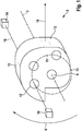
- FIG. 1 a shift actuator 2 according to a first embodiment of the invention is shown.
- the shift actuator 2 can be rotatably placed about a rotation axis 3.
- the rotation axis 3 extends in the present embodiment by a radial bearing 4, which is exemplified as a bore, and through which a bearing shaft, not shown, can be performed.
- This bearing shaft can be driven by an auxiliary motor, not shown, to rotate the shift actuator.
- the bearing shaft may be formed integrally with the shift actuator 2.
- the shift actuator 2 has a circumference 6 which is spirally wound around the radial bearing 4. If the shift actuator 2 is rotated by the auxiliary motor to the radial bearing 4 in a direction 8, the shift actuator 2 can apply a directed away from the radial bearing 4 normal force 10 to a part, such as a still to be described switching shaft of a transmission, not shown, from the axis of rotation 3 push away.
- the spiral circumference 6 therefore serves as a sliding element.
- the shift actuator 2 can have position bores 12 which can be placed around the radial bearing 4 in a circle 15.
- FIG. 1 is only one position bore 12 provided with a reference numeral, which is representative of all position holes 12 on the circle 15 applies.
- the position of the Wegaktuators 2 can be detected when one of the position holes 12 pass the signal generator 14 and the signal receiver 16 receives a signal 18 from the signal generator 14.
- FIG. 2 shows a Geretellaktuator 20 with the shift actuator 2 from FIG. 1 ,
- FIG. 2 become too FIG. 1 the same elements with the same reference numerals and not described again.
- the Geretellaktuator on the aforementioned shift shaft 22 In addition to the shift actuator 2, the Geretellaktuator on the aforementioned shift shaft 22.
- the shift shaft 20 consists of a driver 24, two clutches 26 and two gear carriers 28, on which the gear wheels, not shown, of the transmission are placed.
- the shift shaft 22 has an axis of rotation 30 about which the transmission gears, not shown, to be supported by the shift shaft 22 are rotated.
- the transmission gears may be rotatably or non-rotatably mounted on the gear carriers 28. If they are rotatably arranged, it is possible to dispense with the couplings 26. In any case, the transmission gears should not move axially on the gear carriers 28.
- the couplings 26 allow the gear carriers 28 to rotate relative to the driver 24.
- the driver 24 protrudes from the rotational axis 30 and is open towards the rotational axis U-shaped. In its opening 32, it can receive the shift actuator 2. If the switching element 2 is rotated in the direction of rotation 8, the radius of the spiral circumference 6 increases and presses against a first inner side 29 of the driver 24. In this way, the switching shaft 22 is moved along the axis of rotation 30 in the image plane to the right.
- a provision of the switching shaft 22 is effected automatically by further rotation of the Wegaktuators 2, when the now on the first inner side 29 opposite second inner side 34 of the driver 24 tapered radius of the spiral circumference 6 begins to increase again and thus presses against the second inner side 34.
- a return element not shown, such as a spring, the driver 24 press firmly against the spiral circumference 6 to allow a return of the switching shaft 22, regardless of the direction of rotation.
- FIG. 3 shows a shift actuator 36 according to a second embodiment of the invention.
- FIG. 3 become too FIG. 1 and 2 the same elements with the same reference numerals and not described again.
- the shift actuator 36 is disc-shaped.
- the helical circumference 6 is now replaced by a first groove 40 and a second groove 42 on the top side 38 of the disc.
- the grooves 40, 42 can engage in a manner to be described, the moving part of the transmission.
- the advantage of the grooves 40, 42 is that they can not only push the moving part of the transmission, but also can pull.
- the signal generator 14 and the signal receiver 16 are constructed in two parts, so that the position determination can proceed via two different position signals 18. If the helical grooves 40, 42 extend less than 360 ° about the axis of rotation 3, the absolute position of the switching actuator 36 can be detected with such an arrangement. This principle is based on the shift actuator FIG. 1 transferable.
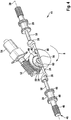
- FIG. 4 shows a Geretellaktuator 44 with the Wegaktuator 36 of Figure 3.
- FIG. 4 become the FIGS. 1 to 3 the same elements with the same reference numerals and not described again.
- the Geretellaktuator a shift shaft 46.
- each three gears 48 mounted On the shift shaft 46 are seen in the image plane left and right each three gears 48 mounted, which can be brought by sliding and pulling the shift shaft 46 with drive wheels on gear shafts, not shown, to produce a specific gear ratio.
- FIG. 4 are for clarity, only the left three gears 48 on the shift shaft 46 provided with a reference numeral.
- the shift actuator 36 has teeth 50 on its circumference and thus forms a gear in which a worm 52 of an auxiliary drive 54 engages.
- This embodiment is particularly advantageous because no power transmission from the shift actuator 36 back to the worm 52 is possible. This will make the in FIG. 1 already described effect of the straight portions 13 of the grooves 40, 42 further increased and a rotation of the Wegaktuators 36 at forces from the selector shaft 46 along the axis of rotation 30 effectively avoided.
- the cam 24 has a telescopic rod 56 on which arms 58 can move apart with the couplings 26 and the gear carriers 28. At the outermost ends 60 directed into the grooves 40, 42 guide mandrels are formed, which in the perspective of the FIG. 4 not to be seen.
- the shift actuator 4 When the shift actuator 4 is rotated in the direction 8, the arms 58 move apart. Will the shift actuator 4 turned counter to the direction 8, the arms 58 move together again.
- the shift actuator according to the invention can move all the necessary gears with a single shift shaft to adjust the various translations in the transmission.
Landscapes
- Engineering & Computer Science (AREA)
- General Engineering & Computer Science (AREA)
- Mechanical Engineering (AREA)
- Gear-Shifting Mechanisms (AREA)
Description
- Die Erfindung betrifft einen Schaltaktuator, insbesondere einen Schaltaktuator zum Auslenken einer Schaltwelle eines Getriebes; eine Schaltwelle, insbesondere eine Schaltwelle zum Schieben eines auf die Schaltwelle aufsetzbaren Getriebezahnrades und einen Getriebestellaktuator mit dem Schaltaktuator und der Schaltwelle.
- Zum Schalten eines mehrstufigen Getriebes ist ein Schaltaktuator notwendig, der die Getriebezahnräder bewegt und miteinander in Eingriff bringt.
- Ein bekannter Schaltaktuator ist eine Schaltwalze. Dabei handelt es sich um einen Rundzylinder, auf dessen Mantelfläche Kanäle eingefräst sind. In jeden Kanal greift ein Führungsdorn einer Schaltgabel ein, die ein Getriebezahnrad hält. Der Verlauf der Kanäle ist derart gelegt, dass in einer bestimmten Stellung der Schaltwalze höchstens zwei Getriebezahnräder miteinander in Eingriff gebracht sind. Der Rundzylinder ist um seine Rotationsachse drehbar gelagert, so dass das Getriebe durch drehen der Schaltwalze geschaltet werden kann.
- Ein Nachteil der Schaltwalze ist sein hoher Platzbedarf.
- Ein weiterer bekannter Schaltaktuator wird durch einen Linearantrieb, wie beispielsweise einen Spindelantrieb betätigt. Hierbei handelt es sich um eine Schaltwelle, auf der die Getriebezahnräder aufgesetzt sind. Der Linearantrieb schiebt oder zieht die Schaltwelle, so dass eines der Getriebezahnräder auf der Schaltwelle mit Zahnrädern auf der Getriebeeingangswelle und auf der Getriebeausgangswelle in Eingriff gebracht wird, um ein bestimmtes Übersetzungsverhältnis herzustellen.
- Ein Nachteil des Linearantriebs ist, dass er eingelegte Getriebegänge teils nicht sicher halten kann.
- Aus der
EP 1 571 378 A1 ist eine Schaltbetätigung für ein automatisiertes Getriebe bekannt. - Aus der
DE 101 60 026 A1 ist ein Betätigungsmechanismus zur Axialverstellung mit doppelter Funktion bekannt. - Aus der
US 2007/0251345 A1 ist ein Zweiganggetriebe mit einer adaptiven Drehmomentübertragungskupplung bekannt. - Aus der
DE 197 58 713 A1 , welche die Präambel des Anspruchs 1 offenbart, ist eine Stelleinrichtung eines in zwei Bewegungsarten bewegbaren Ausgangsteils bekannt. - Es ist daher Aufgabe der Erfindung, einen verkleinerten Aktuator zum Schalten eines mehrstufigen Getriebes anzugeben, der die im Getriebe eingelegten Gänge sicher halten kann.
- Die Aufgabe wird durch den Schaltaktuator nach Anspruch 1 sowie durch die Schaltwelle und den Getriebestellaktuator gemäß den nebengeordneten Ansprüchen gelöst.
- Weitere vorteilhafte Ausgestaltungen sind in den abhängigen Ansprüchen angegeben.
- Gemäß einem ersten Aspekt der Erfindung umfasst ein Schaltaktuator zum Auslenken einer Schaltwelle eines Getriebes
- ein Radiallager mit einer Rotationsachse, um die der Schaltaktuator drehend lagerbar ist; und
- ein Schiebeelement zum Auslenken der Schaltwelle, wenn sich der Schaltaktuator um das Radiallager dreht,
- wobei eine Ausrichtung der Rotationsachse des Radiallagers zur Auslenkungsrichtung verschieden, insbesondere rechtwinklig, ist.
- Dem erfindungsgemäßen Schaltaktuator liegt der Gedanke zugrunde, dass bei einem durch einen Linearantrieb betätigten herkömmlichen Schaltaktuator alle Kräfte, also die Stellkräfte und die Störkräfte auf einer Achse liegen. Schüttelbelastungen des Getriebes, wirken in axialer Richtung auf die Schaltwelle genauso wie die vom Linearantrieb übertragenen Stellkräfte. Auf diese Weise kann der herkömmliche durch einen Linearantrieb betätigte Schaltaktuator die Störkräfte nicht hemmen, da er sonst gleichzeitig die gewünschten Stellkräfte ebenfalls hemmen würde. Beim erfindungsgemäßen Schaltaktuator wird daher vorgeschlagen die den Angriffspunkt der Stellkräfte aus der Wirkrichtung der Störkräfte zu entfernen. Dies wird dadurch erreicht, dass die Stellkräfte den Schaltaktuator drehen und dieser die Stellkräfte in die herkömmliche lineare Stellkraft umwandelt, um die Schaltwelle zu bewegen. Der erfindungsgemäße Schaltaktuator hat den Vorteil dass er im Gegensatz zu einer Schaltwalze mit der Schaltwelle alle notwendigen Zahnräder eines Getriebes bewegen kann, um die einzelnen Übersetzungsverhältnisse einzustellen, anders als beim Linearantrieb wird der Antrieb des Schaltaktuators jedoch nicht in Bewegungsrichtung angesetzt sondern rechtwinklig dazu. Dadurch werden weniger aus einem Getriebe resultierende, zur Schaltwelle axiale Kräfte auf den Antrieb übertragen, die die Lage des Schaltaktuators verstellen können. Schüttelbelastungen des Schaltaktuators werden so besser gehemmt.
- Das Schiebeelement kann spiralförmig um die Rotationsachse gelegt sein. So lässt sich mit dem Schaltaktuator ein kontinuierlicher Stellbereich für eine Schaltwelle realisieren, in der jede beliebige Stellposition angefahren werden kann. Darüber hinaus sind der Kraft- und damit der Energieaufwand zum Positionieren der Schaltwelle klein.
- Das spiralförmige Schiebeelement kann eine Nut zur Aufnahme eines Stiftes aus der Schaltwelle aufweisen. Durch die Nut kann der Schaltaktuator die Schaltwelle, nicht nur schieben, sondern auch ziehen, da die Nut den Stift unabhängig von der Drehrichtung des Schaltaktuators greifen kann.
- Das spiralförmige Schiebeelement kann mit maximal 360° um die Rotationsachse gelegt sein. Auf diese Weise kann einer bestimmten Winkelstellung des Schaltaktuators eindeutig eine Getriebestufe zugeordnet werden, wodurch eine aktuell eingelegte Getriebestufe auf einfache Weise durch Ermittlung der Absolutposition des Schaltaktuators ermittelt werden kann.
- Das spiralförmige Schiebeelement kann Abschnitte aufweisen, in der die Steigung des spiralförmigen Schiebeelementes von der Rotationsachse aus gesehen Null ist. Diese Abschnitte ohne Steigung können eine axiale Kraftübertragung von einer Schaltwelle auf den Schaltaktuator weiter reduzieren und so Schüttelbelastungen des Schaltaktuators durch die Schaltwelle besser hemmen.
- Der Schaltaktuator kann ein Zahnrad aufweisen, auf dessen Grundfläche und/oder oder Deckfläche das Schiebelement angeordnet sein kann. Über das Zahnrad lässt sich der Schaltaktuator auf einfache Weise antreiben.
- Der Schaltaktuator kann ferner einen Positionsgeber aufweisen, aus dem die Position des Schaltaktuators auslesbar ist. Dieser Positionsgeber kann aktiv oder passiv ausgestaltet sein. In einer besonderen Ausbildung ist der Positionsgeber eine einfache Bohrung, wobei die Position selbst beispielsweise mit Licht erfasst werden kann.
- Gemäß einem zweiten Aspekt der Erfindung umfasst eine Schaltwelle zum Schieben eines auf die Schaltwelle aufsetzbaren Getriebezahnrades:
- eine Rotationsachse, um die wenigstens ein Teil der Schaltwelle drehbar gelagert ist; und
- einen von der Rotationsachse abragenden Mitnehmer, zum Anlegen an das Schiebeelement eines angegebenen Schaltaktuators.
- Der Mitnehmer kann einen Stift aufweisen, die zum Eingreifen in eine Nut eines angegebenen Schaltelements vorgesehen ist. Auf diese Weise lässt sich die Schaltwelle schieben und ziehen.
- Gemäß einem zweiten Aspekt der Erfindung umfasst ein Getriebestellaktuator:
- eine axial verstellbare angegebene Schaltwelle; und
- einen angegeben Schaltaktuator,
- wobei der Mitnehmer der Schaltwelle an das Schiebelement des Schaltaktuators angelegt ist.
- Bevorzugte Ausführungsformen der vorliegenden Erfindung werden nachfolgend anhand der beigefügten Zeichnungen näher erläutert. Es zeigen:
-
Figur 1 einen Schaltaktuator gemäß einem ersten Ausführungsbeispiel der Erfindung; -
Figur 2 einen Getriebestellaktuator mit dem Schaltaktuator ausFigur 1 ; -
Figur 3 einen Schaltaktuator gemäß einem ersten Ausführungsbeispiel der Erfindung; und -
Figur 4 einen Getriebestellaktuator mit dem Schaltaktuator ausFigur 3 . - In
Figur 1 ist ein Schaltaktuator 2 gemäß einem ersten Ausführungsbeispiel der Erfindung gezeigt. - Der Schaltaktuator 2 kann drehbar um eine Rotationsachse 3 gelegt werden. Die Rotationsachse 3 verläuft in der vorliegenden Ausführung durch ein Radiallager 4, das beispielhaft als Bohrung ausgeführt ist, und durch das eine nicht gezeigte Lagerwelle geführt werden kann. Diese Lagerwelle kann durch einen nicht gezeigten Hilfsmotor angetrieben werden, um den Schaltaktuator zu drehen. Alternativ kann die Lagerwelle einstückig mit dem Schaltaktuator 2 ausgebildet sein.
- Der Schaltaktuator 2 weist einen Umfang 6 auf, der spiralförmig um das Radiallager 4 gelegt ist. Wird der Schaltaktuator 2 durch den Hilfsmotor um das Radiallager 4 in eine Richtung 8 gedreht, so kann der Schaltaktuator 2 eine vom Radiallager 4 weggerichtete Normalkraft 10 aufbringen, um ein Teil, wie beispielsweise eine noch zu beschreibende Schaltwelle eines nicht gezeigten Getriebes, von der Rotationsachse 3 wegzuschieben. Der spiralförmige Umfang 6 dient daher als Schiebeelement.
- Um die Aufnahme von den Normalkräften 10 entgegen gerichteten Kräften aus dem zu schiebenden Teil zu ermöglichen, ohne dass der Schaltaktuator 2 durch das zu schiebende Teil gedreht wird, kann er an seinem spiralförmigen Umfang 6 an bestimmten Postionen Abschnitte 13 ohne Steigung aufweisen. Diese Abschnitte 13 verlaufen damit tangential zur Rotationsachse 3 und damit senkrecht zur Normalkraft 10, so dass in diesen Abschnitten 13 keine axialen Verstell-Kräfte und Verstell-Drehmomente resultierend aus Schüttelbelastung der Schaltwelle auf den Schaltaktuator 2 übertragen werden können. Schüttelbelastungen des Schaltaktuators 2 können so wirksamer gemindert werden, da die geraden Abschnitte 13 aus dem bewegten Teil resultierende Axialkräfte wirksamer hemmen.
- Zur Ermittlung der Position des an den spiralförmigen Umfang 6 anliegenden bewegten Teils kann der Schaltaktuator 2 Positionsbohrungen 12 aufweisen, die in einem Kreis 15 um das Radiallager 4 gelegt sein können. In
Figur 1 ist nur eine Positionsbohrung 12 mit einem Bezugszeichen versehen, das jedoch stellvertretend für alle Positionsbohrungen 12 auf dem Kreis 15 gilt. Wird statorseitig, beispielsweise an einem nicht gezeigten Gehäuse des Getriebes mit dem Schaltaktuator 2 ein Signalgeber 14, wie beispielsweise eine Leuchtdiode und ein Signalempfänger 16, wie beispielsweise eine Photodiode, auf einer Höhe des Kreises 15 angeordnet, und wird der Schaltaktuator 2 zwischen dem Signalgeber 14 und dem Signalempfänger 16 angebracht, so kann die Position des Schaltaktuators 2 erfasst werden, wenn eine der Positionsbohrungen 12 den Signalgeber 14 passieren und der Signalempfänger 16 ein Signal 18 aus dem Signalgeber 14 empfängt. -
Figur 2 zeigt einen Getriebestellaktuator 20 mit dem Schaltaktuator 2 ausFigur 1 . InFigur 2 werden zuFigur 1 gleiche Elemente mit gleichen Bezugszeichen versehen und nicht noch einmal beschrieben. Neben dem Schaltaktuator 2 weist der Getriebestellaktuator die bereits erwähnte Schaltwelle 22 auf. - Die Schaltwelle 20 besteht aus einem Mitnehmer 24, zwei Kupplungen 26 und zwei Zahnradträgern 28, auf der die nicht gezeigten Zahnräder des Getriebes aufgesetzt sind.
- Die Schaltwelle 22 weist eine Rotationsachse 30 auf, um die die durch die Schaltwelle 22 zu tragenden nicht gezeigte Getriebezahnräder gedreht werden. Die Getriebezahnräder können auf den Zahnradträgern 28 drehbar oder drehfest angeordnet sein. Sind sie drehbar angeordnet, so kann auf die Kupplungen 26 verzichtet werden. In jedem Fall sollten sich die Getriebezahnräder auf den Zahnradträgern 28 axial nicht verschieben lassen.
- Die Kupplungen 26 ermöglichen den Zahnradträgern 28 sich gegenüber dem Mitnehmer 24 zu drehen. Der Mitnehmer 24 ragt von der Rotationsachse 30 ab und ist zur Rotationsachse hin U-förmig geöffnet. In seiner Öffnung 32 kann er das Schaltaktuator 2 aufnehmen. Wird das Schaltelement 2 in Rotationsrichtung 8 gedreht, so vergrößert sich der Radius des spiralförmigen Umfangs 6 und drückt gegen eine erste Innenseite 29 des Mitnehmers 24. Auf diese Weise wird die Schaltwelle 22 entlang der Rotationsachse 30 in der Bildebene nach rechts bewegt.
- Eine Rückstellung der Schaltwelle 22 erfolgt automatisch durch Weiterdrehen des Schaltaktuators 2, wenn sich der nun auf der, der ersten Innenseite 29 gegenüberliegenden zweiten Innenseite 34 des Mitnehmers 24 verjüngte Radius des spiralförmigen Umfangs 6 wieder beginnt zu vergrößern und damit gegen die zweite Innenseite 34 drückt. Alternativ oder zusätzlich kann ein nicht gezeigtes Rückstellelement, wie eine Feder, den Mitnehmer 24 fest gegen den spiralförmigen Umfang 6 drücken, um ein Rückstellen der Schaltwelle 22 unabhängig von der Drehrichtung zu ermöglichen.
-
Figur 3 zeigt einen Schaltaktuator 36 gemäß einem zweiten Ausführungsbeispiel der Erfindung. InFigur 3 werden zuFigur 1 und2 gleiche Elemente mit gleichen Bezugszeichen versehen und nicht noch einmal beschrieben. - Der Schaltaktuator 36 ist scheibenförmig aufgebaut. Der spiralförmige Umfang 6 ist nun durch eine erste Nut 40 und eine zweite Nut 42 auf der Deckseite 38 der Scheibe ersetzt. In die Nuten 40, 42 kann in einer noch zu beschreibenden Weise das zu bewegende Teil des Getriebes eingreifen. Der Vorteil der Nuten 40, 42 ist, dass sie das zu bewegende Teil des Getriebes nicht nur schieben, sondern auch ziehen können.
- In
Figur 3 sind der Signalgeber 14 und der Signalempfänger 16 zweiteilig aufgebaut, so dass die Positionsbestimmung über zwei verschiedene Positionssignale 18 ablaufen kann. Erstrecken sich die spiralförmigen Nuten 40, 42 um weniger als 360°, um die Rotationsachse 3, so kann mit einer derartigen Anordnung die Absolutposition des Schaltaktuators 36 erfasst werden. Dieses Prinzip ist auf den Schaltaktuator ausFigur 1 übertragbar. -
Figur 4 zeigt einen Getriebestellaktuator 44 mit dem Schaltaktuator 36 aus Figur 3. InFigur 4 werden zu denFiguren 1 bis 3 gleiche Elemente mit gleichen Bezugszeichen versehen und nicht noch einmal beschrieben. Neben dem Schaltaktuator 36 weist der Getriebestellaktuator eine Schaltwelle 46 auf. - Auf der Schaltwelle 46 sind in die Bildebene hinein gesehen links und rechts jeweils drei Zahnräder 48 angebracht, die durch ein Schieben und ziehen der Schaltwelle 46 mit Antriebsrädern auf nicht gezeigten Getriebewellen in Eingriff gebracht werden können, um ein bestimmtes Übersetzungsverhältnis herzustellen. In
Figur 4 sind der Übersichtlichkeit halber nur die linken drei Zahnräder 48 auf der Schaltwelle 46 mit einem Bezugszeichen versehen. - Der Schaltaktuator 36 weist an seinem Umfang Zähne 50 auf und bildet so ein Zahnrad, in das eine Schnecke 52 eines Hilfsantriebs 54 eingreift. Diese Ausführung ist besonders vorteilhaft, da keine Kraftübertragung vom Schaltaktuator 36 zurück auf die Schnecke 52 möglich ist. Dadurch wird die in
Figur 1 bereits beschriebene Wirkung der geraden Abschnitte 13 der Nuten 40, 42 weiter gesteigert und eine Drehung des Schaltaktuators 36 bei Kräften aus der Schaltwelle 46 entlang der Rotationsachse 30 wirksamer vermieden. - In der vorliegenden Ausführungsform weist der Mitnehmer 24 eine Teleskopstange 56 auf, auf der sich Arme 58 mit den Kupplungen 26 und den Zahnradträgern 28 auseinanderbewegen können. An den äußersten Enden 60 sind in die Nuten 40, 42 hinein gerichtete Führungsdorne ausgebildet, die in der Perspektive der
Figur 4 nicht zu sehen sind. Wird der Schaltaktuator 4 in die Richtung 8 gedreht, so bewegen sich die Arme 58 auseinander. Wird der Schaltaktuator 4 entgegen der Richtung 8 gedreht, so bewegen sich die wieder Arme 58 zusammen. - Der erfindungsgemäße Schaltaktuator kann mit einer einzigen Schaltwelle alle notwendigen Zahnräder bewegen, um im Getriebe die verschiedenen Übersetzungen einzustellen.
Claims (6)
- Schaltaktuator mit einer auslenkbaren Schaltwelle (46) eines Getriebes, umfassend:- ein Radiallager (4) mit einer Rotationsachse (3), um die der Schaltaktuator (36) drehend lagerbar ist; und- ein Schiebeelement (40, 42), das die Schaltwelle (22, 46) auslenkt, wenn sich der Schaltaktuator (36) um das Radiallager (4) dreht,- wobei eine Ausrichtung der Rotationsachse (3) des Radiallagers (4) zurdadurch gekennzeichnet, dass
Auslenkungsrichtung verschieden, insbesondere rechtwinklig, ist,
das Schiebeelement (40, 42) spiralförmig um die Rotationsachse (3) verläuft, wobei das spiralförmige Schiebeelement (40, 42) eine Nut (40, 42) zur Aufnahme eines Stiftes aus der Schaltwelle (46) ist. - Schaltaktuator nach Anspruch 1, wobei das spiralförmige Schiebeelement (6, 40, 42) mit maximal 360° um die Rotationsachse (3) gelegt ist.
- Schaltaktuator nach einem der Ansprüche 1 oder 2, wobei das spiralförmige Schiebeelement (6, 40, 42) Abschnitte (13) aufweist, in der die Steigung des spiralförmigen Schiebeelementes (6, 40, 42) von der Rotationsachse (3) aus gesehen Null ist.
- Schaltaktuator nach einem der vorstehenden Ansprüche umfassend ein Zahnrad (50), auf dessen Grundfläche und/oder oder Deckfläche (38) das Schiebelement (6, 40, 42) angeordnet ist.
- Schaltaktuator nach einem der vorstehenden Ansprüche umfassend einen Positionsgeber (12).
- Getriebestellaktuator umfassend:- Einen Schaltaktuator nach einem der Ansprüche 1 bis 5, - die axial verstellbare Schaltwelle (46) zum Schieben eines auf die Schaltwelle (46) aufsetzbaren Getriebezahnrades (48); und- eine zweite Rotationsachse (30) um die wenigstens ein Teil der Schaltwelle gelagert ist und ein von dieser zweiten Rotationsachse (30) abragender Mitnehmer (24), zum Anlegen an das Schiebeelement (40, 42) eines Schaltaktuators (36), wobei der Mitnehmer (24) einen Stift aufweist, der zum Eingreifen in die Nut (40, 42) des Schaltaktuators (36) vorgesehen ist,
wobei der Mitnehmer (24) der Schaltwelle (46) an das Schiebelement (40, 42) des Schaltaktuators (2, 36) angelegt ist.
Applications Claiming Priority (2)
| Application Number | Priority Date | Filing Date | Title |
|---|---|---|---|
| DE102011078360A DE102011078360A1 (de) | 2011-06-29 | 2011-06-29 | Schaltaktuator zum Auslenken einer Schaltwelle eines Getriebes |
| PCT/EP2012/060460 WO2013000664A1 (de) | 2011-06-29 | 2012-06-04 | Schaltaktuator zum auslenken einer schaltwelle eines getriebes |
Publications (2)
| Publication Number | Publication Date |
|---|---|
| EP2726762A1 EP2726762A1 (de) | 2014-05-07 |
| EP2726762B1 true EP2726762B1 (de) | 2017-10-04 |
Family
ID=46275810
Family Applications (1)
| Application Number | Title | Priority Date | Filing Date |
|---|---|---|---|
| EP12727345.6A Not-in-force EP2726762B1 (de) | 2011-06-29 | 2012-06-04 | Schaltaktuator zum auslenken einer schaltwelle eines getriebes |
Country Status (4)
| Country | Link |
|---|---|
| EP (1) | EP2726762B1 (de) |
| CN (1) | CN103765056B (de) |
| DE (1) | DE102011078360A1 (de) |
| WO (1) | WO2013000664A1 (de) |
Families Citing this family (1)
| Publication number | Priority date | Publication date | Assignee | Title |
|---|---|---|---|---|
| DE102013213888B3 (de) * | 2013-07-16 | 2014-11-13 | Robert Bosch Gmbh | Elektrohydraulischer Aktuator |
Citations (1)
| Publication number | Priority date | Publication date | Assignee | Title |
|---|---|---|---|---|
| DE19758713A1 (de) * | 1996-09-23 | 2002-05-16 | Zf Sachs Ag | Stelleinrichtung eines in zwei Bewegungsarten bewegbaren Ausgangsteils |
Family Cites Families (6)
| Publication number | Priority date | Publication date | Assignee | Title |
|---|---|---|---|---|
| JP2000320668A (ja) * | 1999-05-13 | 2000-11-24 | Aichi Mach Ind Co Ltd | 歯車式変速機の自動変速装置 |
| DE10160026B9 (de) * | 2001-12-06 | 2008-06-12 | Gkn Driveline International Gmbh | Betätigungsmechanismus zur Axialverstellung mit doppelter Funktion |
| DE502004006250D1 (de) * | 2004-03-02 | 2008-04-03 | Getrag Ford Transmissions Gmbh | Schaltbetätigung für ein automatisiertes Getriebe |
| US7694598B2 (en) * | 2006-04-26 | 2010-04-13 | Magna Powertrain Ag & Co Kg | Two-speed transfer case with adaptive torque transfer clutch |
| JP2008232262A (ja) * | 2007-03-20 | 2008-10-02 | Daihatsu Motor Co Ltd | 変速機の変速操作装置 |
| CN101504070B (zh) * | 2009-03-09 | 2013-12-11 | 力帆实业(集团)股份有限公司 | 一种电动汽车变挡系统 |
-
2011
- 2011-06-29 DE DE102011078360A patent/DE102011078360A1/de not_active Withdrawn
-
2012
- 2012-06-04 CN CN201280032398.6A patent/CN103765056B/zh not_active Expired - Fee Related
- 2012-06-04 EP EP12727345.6A patent/EP2726762B1/de not_active Not-in-force
- 2012-06-04 WO PCT/EP2012/060460 patent/WO2013000664A1/de not_active Ceased
Patent Citations (1)
| Publication number | Priority date | Publication date | Assignee | Title |
|---|---|---|---|---|
| DE19758713A1 (de) * | 1996-09-23 | 2002-05-16 | Zf Sachs Ag | Stelleinrichtung eines in zwei Bewegungsarten bewegbaren Ausgangsteils |
Also Published As
| Publication number | Publication date |
|---|---|
| WO2013000664A1 (de) | 2013-01-03 |
| CN103765056A (zh) | 2014-04-30 |
| EP2726762A1 (de) | 2014-05-07 |
| CN103765056B (zh) | 2016-09-21 |
| DE102011078360A1 (de) | 2013-01-03 |
Similar Documents
| Publication | Publication Date | Title |
|---|---|---|
| EP2098743B1 (de) | Stellmechanismus zum Ein- und Ausrücken einer Trennkupplung mit drehbarem Kurvensegment | |
| DE102009029532B4 (de) | Lenkventil mit Planetengetriebe | |
| DE102005061268B4 (de) | Reibungskupplung mit Aktuator und Tellerfeder | |
| DE69503048T2 (de) | Eine umlaufräder-gangschaltvorrichtung | |
| EP2384962A1 (de) | Rücktrittgetriebe für Elektrofahrräder und Verfahren zur gesteuerten Kopplung von Abtrieb und Motor eines Elektrofahrrads | |
| WO2005038286A1 (de) | Azimutbremse für windkraftanlagen | |
| WO2014044390A1 (de) | Spannsystem mit einem rotationsantrieb | |
| EP2837852B1 (de) | Schaltanordnung mit einer Kupplungs- und Synchronisierungseinrichtung für ein Getriebe | |
| EP4728208A1 (de) | Aktor zur bereitstellung eines drehmoments mit einem linearantrieb | |
| DE102016221158A1 (de) | Betätigungseinheit und Aktor für ein Automatikgetriebe sowie Verwendung eines Antriebsmoduls für eine solche Betätigungseinheit | |
| EP4323265A1 (de) | Fahrradtretlagergetriebe mit miteinander gekoppelten kupplungsvorrichtungen | |
| DE102005000886B4 (de) | Getriebeeinrichtung und Betätigungsvorrichtung zum Betätigen eines Getriebes, insbesondere Kraftfahrzeuggetriebes | |
| EP0859173B1 (de) | Schaltvorrichtung für ein mehrgängiges Wechselgetriebe eines Kraftfahrzeugs | |
| EP2557335B1 (de) | Kraftübertragungsvorrichtung für ein Getriebe | |
| EP2726762A1 (de) | Schaltaktuator zum auslenken einer schaltwelle eines getriebes | |
| DE102011055995B4 (de) | Kraftübertragungsvorrichtung für ein Getriebe | |
| EP4323264A1 (de) | Fahrradtretlagergetriebe mit miteinander gekoppelten kupplungsvorrichtungen | |
| DE202008017689U1 (de) | Planetengetriebe für ein Elektrohandwerkzeuggerät sowie Elektrohandwerkzeuggerät | |
| DE102023111774B4 (de) | Verstellaktuator für Lenkeinrichtung | |
| EP3835621B1 (de) | Stellantrieb | |
| EP1596103B1 (de) | Stelleinheit zur automatisierten Betätigung eines Schaltgetriebes | |
| DE10338811B4 (de) | Automatische Gangschaltung für Fahrräder | |
| DE102014210777A1 (de) | Kupplungsbaugruppe für die Kupplungsbetätigung in einem Fahrzeuggetriebe | |
| DE102008043562A1 (de) | Schaltanordnung | |
| DE19727946A1 (de) | Schaltvorrichtung für ein mehrgängiges Wechselgetriebe eines Kraftfahrzeugs |
Legal Events
| Date | Code | Title | Description |
|---|---|---|---|
| PUAI | Public reference made under article 153(3) epc to a published international application that has entered the european phase |
Free format text: ORIGINAL CODE: 0009012 |
|
| 17P | Request for examination filed |
Effective date: 20140129 |
|
| AK | Designated contracting states |
Kind code of ref document: A1 Designated state(s): AL AT BE BG CH CY CZ DE DK EE ES FI FR GB GR HR HU IE IS IT LI LT LU LV MC MK MT NL NO PL PT RO RS SE SI SK SM TR |
|
| DAX | Request for extension of the european patent (deleted) | ||
| 17Q | First examination report despatched |
Effective date: 20141105 |
|
| GRAP | Despatch of communication of intention to grant a patent |
Free format text: ORIGINAL CODE: EPIDOSNIGR1 |
|
| INTG | Intention to grant announced |
Effective date: 20170703 |
|
| GRAA | (expected) grant |
Free format text: ORIGINAL CODE: 0009210 |
|
| GRAS | Grant fee paid |
Free format text: ORIGINAL CODE: EPIDOSNIGR3 |
|
| AK | Designated contracting states |
Kind code of ref document: B1 Designated state(s): AL AT BE BG CH CY CZ DE DK EE ES FI FR GB GR HR HU IE IS IT LI LT LU LV MC MK MT NL NO PL PT RO RS SE SI SK SM TR |
|
| REG | Reference to a national code |
Ref country code: GB Ref legal event code: FG4D Free format text: NOT ENGLISH |
|
| REG | Reference to a national code |
Ref country code: CH Ref legal event code: EP |
|
| REG | Reference to a national code |
Ref country code: AT Ref legal event code: REF Ref document number: 934362 Country of ref document: AT Kind code of ref document: T Effective date: 20171015 |
|
| REG | Reference to a national code |
Ref country code: IE Ref legal event code: FG4D Free format text: LANGUAGE OF EP DOCUMENT: GERMAN |
|
| REG | Reference to a national code |
Ref country code: DE Ref legal event code: R096 Ref document number: 502012011386 Country of ref document: DE |
|
| REG | Reference to a national code |
Ref country code: NL Ref legal event code: MP Effective date: 20171004 |
|
| REG | Reference to a national code |
Ref country code: LT Ref legal event code: MG4D |
|
| PG25 | Lapsed in a contracting state [announced via postgrant information from national office to epo] |
Ref country code: NL Free format text: LAPSE BECAUSE OF FAILURE TO SUBMIT A TRANSLATION OF THE DESCRIPTION OR TO PAY THE FEE WITHIN THE PRESCRIBED TIME-LIMIT Effective date: 20171004 |
|
| PG25 | Lapsed in a contracting state [announced via postgrant information from national office to epo] |
Ref country code: LT Free format text: LAPSE BECAUSE OF FAILURE TO SUBMIT A TRANSLATION OF THE DESCRIPTION OR TO PAY THE FEE WITHIN THE PRESCRIBED TIME-LIMIT Effective date: 20171004 Ref country code: NO Free format text: LAPSE BECAUSE OF FAILURE TO SUBMIT A TRANSLATION OF THE DESCRIPTION OR TO PAY THE FEE WITHIN THE PRESCRIBED TIME-LIMIT Effective date: 20180104 Ref country code: SE Free format text: LAPSE BECAUSE OF FAILURE TO SUBMIT A TRANSLATION OF THE DESCRIPTION OR TO PAY THE FEE WITHIN THE PRESCRIBED TIME-LIMIT Effective date: 20171004 Ref country code: FI Free format text: LAPSE BECAUSE OF FAILURE TO SUBMIT A TRANSLATION OF THE DESCRIPTION OR TO PAY THE FEE WITHIN THE PRESCRIBED TIME-LIMIT Effective date: 20171004 Ref country code: ES Free format text: LAPSE BECAUSE OF FAILURE TO SUBMIT A TRANSLATION OF THE DESCRIPTION OR TO PAY THE FEE WITHIN THE PRESCRIBED TIME-LIMIT Effective date: 20171004 |
|
| PG25 | Lapsed in a contracting state [announced via postgrant information from national office to epo] |
Ref country code: BG Free format text: LAPSE BECAUSE OF FAILURE TO SUBMIT A TRANSLATION OF THE DESCRIPTION OR TO PAY THE FEE WITHIN THE PRESCRIBED TIME-LIMIT Effective date: 20180104 Ref country code: LV Free format text: LAPSE BECAUSE OF FAILURE TO SUBMIT A TRANSLATION OF THE DESCRIPTION OR TO PAY THE FEE WITHIN THE PRESCRIBED TIME-LIMIT Effective date: 20171004 Ref country code: RS Free format text: LAPSE BECAUSE OF FAILURE TO SUBMIT A TRANSLATION OF THE DESCRIPTION OR TO PAY THE FEE WITHIN THE PRESCRIBED TIME-LIMIT Effective date: 20171004 Ref country code: HR Free format text: LAPSE BECAUSE OF FAILURE TO SUBMIT A TRANSLATION OF THE DESCRIPTION OR TO PAY THE FEE WITHIN THE PRESCRIBED TIME-LIMIT Effective date: 20171004 Ref country code: IS Free format text: LAPSE BECAUSE OF FAILURE TO SUBMIT A TRANSLATION OF THE DESCRIPTION OR TO PAY THE FEE WITHIN THE PRESCRIBED TIME-LIMIT Effective date: 20180204 Ref country code: GR Free format text: LAPSE BECAUSE OF FAILURE TO SUBMIT A TRANSLATION OF THE DESCRIPTION OR TO PAY THE FEE WITHIN THE PRESCRIBED TIME-LIMIT Effective date: 20180105 |
|
| REG | Reference to a national code |
Ref country code: FR Ref legal event code: PLFP Year of fee payment: 7 |
|
| REG | Reference to a national code |
Ref country code: DE Ref legal event code: R097 Ref document number: 502012011386 Country of ref document: DE |
|
| PG25 | Lapsed in a contracting state [announced via postgrant information from national office to epo] |
Ref country code: CZ Free format text: LAPSE BECAUSE OF FAILURE TO SUBMIT A TRANSLATION OF THE DESCRIPTION OR TO PAY THE FEE WITHIN THE PRESCRIBED TIME-LIMIT Effective date: 20171004 Ref country code: DK Free format text: LAPSE BECAUSE OF FAILURE TO SUBMIT A TRANSLATION OF THE DESCRIPTION OR TO PAY THE FEE WITHIN THE PRESCRIBED TIME-LIMIT Effective date: 20171004 Ref country code: EE Free format text: LAPSE BECAUSE OF FAILURE TO SUBMIT A TRANSLATION OF THE DESCRIPTION OR TO PAY THE FEE WITHIN THE PRESCRIBED TIME-LIMIT Effective date: 20171004 Ref country code: SK Free format text: LAPSE BECAUSE OF FAILURE TO SUBMIT A TRANSLATION OF THE DESCRIPTION OR TO PAY THE FEE WITHIN THE PRESCRIBED TIME-LIMIT Effective date: 20171004 |
|
| PLBE | No opposition filed within time limit |
Free format text: ORIGINAL CODE: 0009261 |
|
| STAA | Information on the status of an ep patent application or granted ep patent |
Free format text: STATUS: NO OPPOSITION FILED WITHIN TIME LIMIT |
|
| PG25 | Lapsed in a contracting state [announced via postgrant information from national office to epo] |
Ref country code: RO Free format text: LAPSE BECAUSE OF FAILURE TO SUBMIT A TRANSLATION OF THE DESCRIPTION OR TO PAY THE FEE WITHIN THE PRESCRIBED TIME-LIMIT Effective date: 20171004 Ref country code: PL Free format text: LAPSE BECAUSE OF FAILURE TO SUBMIT A TRANSLATION OF THE DESCRIPTION OR TO PAY THE FEE WITHIN THE PRESCRIBED TIME-LIMIT Effective date: 20171004 Ref country code: SM Free format text: LAPSE BECAUSE OF FAILURE TO SUBMIT A TRANSLATION OF THE DESCRIPTION OR TO PAY THE FEE WITHIN THE PRESCRIBED TIME-LIMIT Effective date: 20171004 |
|
| 26N | No opposition filed |
Effective date: 20180705 |
|
| PG25 | Lapsed in a contracting state [announced via postgrant information from national office to epo] |
Ref country code: MT Free format text: LAPSE BECAUSE OF FAILURE TO SUBMIT A TRANSLATION OF THE DESCRIPTION OR TO PAY THE FEE WITHIN THE PRESCRIBED TIME-LIMIT Effective date: 20171004 |
|
| PG25 | Lapsed in a contracting state [announced via postgrant information from national office to epo] |
Ref country code: SI Free format text: LAPSE BECAUSE OF FAILURE TO SUBMIT A TRANSLATION OF THE DESCRIPTION OR TO PAY THE FEE WITHIN THE PRESCRIBED TIME-LIMIT Effective date: 20171004 |
|
| REG | Reference to a national code |
Ref country code: CH Ref legal event code: PL |
|
| GBPC | Gb: european patent ceased through non-payment of renewal fee |
Effective date: 20180604 |
|
| REG | Reference to a national code |
Ref country code: BE Ref legal event code: MM Effective date: 20180630 |
|
| REG | Reference to a national code |
Ref country code: IE Ref legal event code: MM4A |
|
| PG25 | Lapsed in a contracting state [announced via postgrant information from national office to epo] |
Ref country code: LU Free format text: LAPSE BECAUSE OF NON-PAYMENT OF DUE FEES Effective date: 20180604 Ref country code: MC Free format text: LAPSE BECAUSE OF FAILURE TO SUBMIT A TRANSLATION OF THE DESCRIPTION OR TO PAY THE FEE WITHIN THE PRESCRIBED TIME-LIMIT Effective date: 20171004 |
|
| PG25 | Lapsed in a contracting state [announced via postgrant information from national office to epo] |
Ref country code: CH Free format text: LAPSE BECAUSE OF NON-PAYMENT OF DUE FEES Effective date: 20180630 Ref country code: LI Free format text: LAPSE BECAUSE OF NON-PAYMENT OF DUE FEES Effective date: 20180630 Ref country code: GB Free format text: LAPSE BECAUSE OF NON-PAYMENT OF DUE FEES Effective date: 20180604 Ref country code: IE Free format text: LAPSE BECAUSE OF NON-PAYMENT OF DUE FEES Effective date: 20180604 |
|
| PG25 | Lapsed in a contracting state [announced via postgrant information from national office to epo] |
Ref country code: BE Free format text: LAPSE BECAUSE OF NON-PAYMENT OF DUE FEES Effective date: 20180630 |
|
| REG | Reference to a national code |
Ref country code: AT Ref legal event code: MM01 Ref document number: 934362 Country of ref document: AT Kind code of ref document: T Effective date: 20180604 |
|
| PGFP | Annual fee paid to national office [announced via postgrant information from national office to epo] |
Ref country code: DE Payment date: 20190822 Year of fee payment: 8 |
|
| PG25 | Lapsed in a contracting state [announced via postgrant information from national office to epo] |
Ref country code: AT Free format text: LAPSE BECAUSE OF NON-PAYMENT OF DUE FEES Effective date: 20180604 |
|
| PG25 | Lapsed in a contracting state [announced via postgrant information from national office to epo] |
Ref country code: TR Free format text: LAPSE BECAUSE OF FAILURE TO SUBMIT A TRANSLATION OF THE DESCRIPTION OR TO PAY THE FEE WITHIN THE PRESCRIBED TIME-LIMIT Effective date: 20171004 |
|
| PG25 | Lapsed in a contracting state [announced via postgrant information from national office to epo] |
Ref country code: HU Free format text: LAPSE BECAUSE OF FAILURE TO SUBMIT A TRANSLATION OF THE DESCRIPTION OR TO PAY THE FEE WITHIN THE PRESCRIBED TIME-LIMIT; INVALID AB INITIO Effective date: 20120604 Ref country code: PT Free format text: LAPSE BECAUSE OF FAILURE TO SUBMIT A TRANSLATION OF THE DESCRIPTION OR TO PAY THE FEE WITHIN THE PRESCRIBED TIME-LIMIT Effective date: 20171004 |
|
| PG25 | Lapsed in a contracting state [announced via postgrant information from national office to epo] |
Ref country code: CY Free format text: LAPSE BECAUSE OF FAILURE TO SUBMIT A TRANSLATION OF THE DESCRIPTION OR TO PAY THE FEE WITHIN THE PRESCRIBED TIME-LIMIT Effective date: 20171004 Ref country code: MK Free format text: LAPSE BECAUSE OF NON-PAYMENT OF DUE FEES Effective date: 20171004 |
|
| PG25 | Lapsed in a contracting state [announced via postgrant information from national office to epo] |
Ref country code: AL Free format text: LAPSE BECAUSE OF FAILURE TO SUBMIT A TRANSLATION OF THE DESCRIPTION OR TO PAY THE FEE WITHIN THE PRESCRIBED TIME-LIMIT Effective date: 20171004 |
|
| PGFP | Annual fee paid to national office [announced via postgrant information from national office to epo] |
Ref country code: FR Payment date: 20200623 Year of fee payment: 9 |
|
| PGFP | Annual fee paid to national office [announced via postgrant information from national office to epo] |
Ref country code: IT Payment date: 20200630 Year of fee payment: 9 |
|
| REG | Reference to a national code |
Ref country code: DE Ref legal event code: R119 Ref document number: 502012011386 Country of ref document: DE |
|
| PG25 | Lapsed in a contracting state [announced via postgrant information from national office to epo] |
Ref country code: DE Free format text: LAPSE BECAUSE OF NON-PAYMENT OF DUE FEES Effective date: 20210101 |
|
| PG25 | Lapsed in a contracting state [announced via postgrant information from national office to epo] |
Ref country code: FR Free format text: LAPSE BECAUSE OF NON-PAYMENT OF DUE FEES Effective date: 20210630 |
|
| PG25 | Lapsed in a contracting state [announced via postgrant information from national office to epo] |
Ref country code: IT Free format text: LAPSE BECAUSE OF NON-PAYMENT OF DUE FEES Effective date: 20210604 |