EP2725339A2 - Particulate matter sensor unit - Google Patents
Particulate matter sensor unit Download PDFInfo
- Publication number
- EP2725339A2 EP2725339A2 EP20120199713 EP12199713A EP2725339A2 EP 2725339 A2 EP2725339 A2 EP 2725339A2 EP 20120199713 EP20120199713 EP 20120199713 EP 12199713 A EP12199713 A EP 12199713A EP 2725339 A2 EP2725339 A2 EP 2725339A2
- Authority
- EP
- European Patent Office
- Prior art keywords
- particulate
- sensor
- electrode portion
- sensor apparatus
- shape
- Prior art date
- Legal status (The legal status is an assumption and is not a legal conclusion. Google has not performed a legal analysis and makes no representation as to the accuracy of the status listed.)
- Withdrawn
Links
Images




Classifications
-
- F—MECHANICAL ENGINEERING; LIGHTING; HEATING; WEAPONS; BLASTING
- F01—MACHINES OR ENGINES IN GENERAL; ENGINE PLANTS IN GENERAL; STEAM ENGINES
- F01N—GAS-FLOW SILENCERS OR EXHAUST APPARATUS FOR MACHINES OR ENGINES IN GENERAL; GAS-FLOW SILENCERS OR EXHAUST APPARATUS FOR INTERNAL-COMBUSTION ENGINES
- F01N11/00—Monitoring or diagnostic devices for exhaust-gas treatment apparatus
-
- G—PHYSICS
- G01—MEASURING; TESTING
- G01N—INVESTIGATING OR ANALYSING MATERIALS BY DETERMINING THEIR CHEMICAL OR PHYSICAL PROPERTIES
- G01N15/00—Investigating characteristics of particles; Investigating permeability, pore-volume or surface-area of porous materials
- G01N15/06—Investigating concentration of particle suspensions
- G01N15/0656—Investigating concentration of particle suspensions using electric, e.g. electrostatic methods or magnetic methods
-
- G—PHYSICS
- G01—MEASURING; TESTING
- G01M—TESTING STATIC OR DYNAMIC BALANCE OF MACHINES OR STRUCTURES; TESTING OF STRUCTURES OR APPARATUS, NOT OTHERWISE PROVIDED FOR
- G01M15/00—Testing of engines
- G01M15/04—Testing internal-combustion engines
- G01M15/10—Testing internal-combustion engines by monitoring exhaust gases or combustion flame
- G01M15/102—Testing internal-combustion engines by monitoring exhaust gases or combustion flame by monitoring exhaust gases
-
- G—PHYSICS
- G01—MEASURING; TESTING
- G01N—INVESTIGATING OR ANALYSING MATERIALS BY DETERMINING THEIR CHEMICAL OR PHYSICAL PROPERTIES
- G01N27/00—Investigating or analysing materials by the use of electric, electrochemical, or magnetic means
- G01N27/02—Investigating or analysing materials by the use of electric, electrochemical, or magnetic means by investigating impedance
- G01N27/22—Investigating or analysing materials by the use of electric, electrochemical, or magnetic means by investigating impedance by investigating capacitance
-
- F—MECHANICAL ENGINEERING; LIGHTING; HEATING; WEAPONS; BLASTING
- F01—MACHINES OR ENGINES IN GENERAL; ENGINE PLANTS IN GENERAL; STEAM ENGINES
- F01N—GAS-FLOW SILENCERS OR EXHAUST APPARATUS FOR MACHINES OR ENGINES IN GENERAL; GAS-FLOW SILENCERS OR EXHAUST APPARATUS FOR INTERNAL-COMBUSTION ENGINES
- F01N2560/00—Exhaust systems with means for detecting or measuring exhaust gas components or characteristics
- F01N2560/05—Exhaust systems with means for detecting or measuring exhaust gas components or characteristics the means being a particulate sensor
Definitions
- a particulate sensor apparatus may include an exhaust line through which exhaust gas flows, and a sensor that is disposed at one side in the exhaust line and generates electrical charges when a particulate passes near vicinity of the sensor, wherein an electrode portion is formed on a front surface of the sensor facing the particulate.
- FIG. 3 is a graph of a charge signal that is induced according to a distance X between a sensor and a particulate.
- the electrode portion 320 protrudes on the front surface 300 of the sensor 120 in a flow direction of exhaust gas by a predetermined distance, and an equipotential line is formed along a groove between electrode portions 320.
- FIG. 7 is a partial detailed cross-sectional side view of a surface of a particulate sensor according to an exemplary embodiment of the present invention. Referring to FIG. 7 , a section of an electrode portion having a furrow shape is shown.
- a horizontal axis denotes a ratio between a width (W) of the electrode portion 320 and a width (S) of a groove
- a vertical axis denotes a size of an equipotential area
- the width (W) and the height (h) are set to 20 ⁇ m, and the distance (s) can be set to one of 20, 40, and 60 ⁇ m.
- FIG. 14 (b) shows a sensor having a nanowire type of electrode portions 320, and the nanowire type of electrode portions 320 has a diameter (d) and a height (h), and a distance (s) is formed between them.
Landscapes
- Chemical & Material Sciences (AREA)
- Engineering & Computer Science (AREA)
- Combustion & Propulsion (AREA)
- Physics & Mathematics (AREA)
- General Physics & Mathematics (AREA)
- Pathology (AREA)
- Health & Medical Sciences (AREA)
- Life Sciences & Earth Sciences (AREA)
- Analytical Chemistry (AREA)
- Biochemistry (AREA)
- General Health & Medical Sciences (AREA)
- Immunology (AREA)
- Dispersion Chemistry (AREA)
- Chemical Kinetics & Catalysis (AREA)
- Mechanical Engineering (AREA)
- General Engineering & Computer Science (AREA)
- Electrochemistry (AREA)
- Processes For Solid Components From Exhaust (AREA)
- Investigating Or Analyzing Materials By The Use Of Electric Means (AREA)
- Other Investigation Or Analysis Of Materials By Electrical Means (AREA)
- Exhaust Gas After Treatment (AREA)
Abstract

Description
- The present application claims priority to Korean Patent Application No.
10-2012-0119183 filed on October 25, 2012 - The present invention relates to a particulate sensor unit that accurately and effectively detects damage to a particulate filter filtering particulate matter (PM) included in exhaust gas, and transmits the detected signal to a control portion.
- A diesel particulate filter (DPF) has been being applied to a diesel vehicle so as to reduce PM thereof, and a pressure difference sensor is applied to detect a PM amount that is trapped in the diesel particulate filter.
- In the future, a pressure difference sensor will not be used to detect damage to the DPF according to exhaust gas regulations, and further, the detection precision of the pressure difference sensor is low.
- The information disclosed in this Background of the Invention section is only for enhancement of understanding of the general background of the invention and should not be taken as an acknowledgement or any form of suggestion that this information forms the prior art already known to a person skilled in the art.
- Various aspects of the present invention are directed to providing a particulate sensor unit having advantages of accurately detecting an amount of PM (particulate matter) that is slipped from a particulate filter and accurately detecting damage to the particulate filter through the detected PM amount.
- In an aspect of the present invention, a particulate sensor apparatus may include an exhaust line through which exhaust gas flows, and a sensor that is disposed at one side in the exhaust line and generates electrical charges when a particulate passes near vicinity of the sensor, wherein an electrode portion is formed on a front surface of the sensor facing the particulate.
- A groove is formed between electrode portions in a direction that crosses a direction that the exhaust gas flows.
- The electrode portions are formed perpendicular to a direction that the exhaust gas flows.
- A cross section of the electrode portion is in a rectangular shape.
- A slanted surface is formed to a lateral side of the electrode portions from an upper end surface thereof to the groove.
- The slanted surface forms an angle ranging from 50 to 60 degrees with respect to the upper end surface of the electrode portions.
- A cross section of the electrode portion is in a trapezoidal shape formed with the slanted surface.
- A cross section of the electrode portion is in a triangular shape formed with the slanted surface.
- The electrode portion is in a pillar shape that protrudes at the front surface of the sensor in the pillar shape.
- The electrode portion may have a width of the electrode portion that is 20 nm, a distance from an adjacent electrode portion that ranges from 20 to 120 nm, and a height thereof that ranges from 20 nm to hundreds of nanometers.
- A slanted surface is formed on lateral sides of the protrude portion to become wider from an upper end surface thereof to the front surface.
- A cross-section of the electrode portion may have a trapezoidal shape.
- A cross section of the electrode portion is in a triangular shape.
- The electrode portion protrudes in the pillar shape, and an exterior diameter thereof is less than 10 nm to be a nano-wire shape.
- The electrode portion is formed with pores that are sunken in a pillar shape.
- The pores may have a cuboidal shape.
- The pores may have a trapezoidal shape to become narrower from an upper surface thereof to a lower surface thereof.
- A diesel particulate filter (DPF) is disposed at an upstream side of the sensor, the sensor generates the electrical charge that is induced by the particulate may include d in the exhaust gas, and a control portion determines whether the diesel particulate filter is damaged or not depending on the electrical charge of the sensor.
- The methods and apparatuses of the present invention have other features and advantages which will be apparent from or are set forth in more detail in the accompanying drawings, which are incorporated herein, and the following Detailed Description, which together serve to explain certain principles of the present invention.
-
FIG. 1 is a graph showing a particulate material amount that is trapped in a diesel particulate filter according to an exemplary embodiment of the present invention. -
FIG. 2 is an interior perspective view showing a condition that a particulate sensor is disposed in an exhaust line according to an exemplary embodiment of the present invention. -
FIG. 3 is a graph showing a charge amount that is generated by a sensor unit depending on distance variation between a sensor and particulate matter according to an exemplary embodiment of the present invention. -
FIG. 4 is a perspective view showing a front side of a particulate sensor according to an exemplary embodiment of the present invention. -
FIG. 5 is a perspective view showing a rear side of a particulate sensor according to an exemplary embodiment of the present invention. -
FIG. 6 is a side view showing exhaust gas flow around a particulate sensor and the surroundings thereof according to an exemplary embodiment of the present invention. -
FIG. 7 is a partial detailed cross-sectional side view of a surface of a particulate sensor according to an exemplary embodiment of the present invention. -
FIG. 8 is a perspective view showing a surface shape of a particulate sensor according to an exemplary embodiment of the present invention. -
FIG. 9 is a graph showing an equipotential line depending on a ratio between a groove and a protrusion that are formed on a surface of a particulate sensor according to an exemplary embodiment of the present invention. -
FIG. 10 (a), (b), and (c) are perspective views showing a groove type that is formed on a surface of a particulate sensor according to an exemplary embodiment of the present invention. -
FIG. 11 (a), (b), and (c) are perspective views showing different types of grooves that are formed on a surface of a particulate sensor according to an exemplary embodiment of the present invention. -
FIG. 12 is a graph showing signals depending on types of grooves that are formed on a surface of a particulate sensor according to an exemplary embodiment of the present invention. -
FIG. 13 is a schematic diagram of an exhaust system in which a sensor is disposed according to an exemplary embodiment of the present invention. -
FIG. 14 is a perspective view showing various types of surfaces of a particulate sensor according to an exemplary embodiment of the present invention. - It should be understood that the appended drawings are not necessarily to scale, presenting a somewhat simplified representation of various features illustrative of the basic principles of the invention. The specific design features of the present invention as disclosed herein, including, for example, specific dimensions, orientations, locations, and shapes will be determined in part by the particular intended application and use environment.
- In the figures, reference numbers refer to the same or equivalent parts of the present invention throughout the several figures of the drawing.
- Reference will now be made in detail to various embodiments of the present invention(s), examples of which are illustrated in the accompanying drawings and described below. While the invention(s) will be described in conjunction with exemplary embodiments, it will be understood that the present description is not intended to limit the invention(s) to those exemplary embodiments. On the contrary, the invention(s) is/are intended to cover not only the exemplary embodiments, but also various alternatives, modifications, equivalents and other embodiments, which may be included within the spirit and scope of the invention as defined by the appended claims.
- An exemplary embodiment of the present invention will hereinafter be described in detail with reference to the accompanying drawings.
-
FIG. 1 is a graph showing a particulate material amount that is trapped in a diesel particulate filter according to an exemplary embodiment of the present invention,FIG. 2 is an interior perspective view showing a condition that a particulate sensor is disposed in an exhaust line according to an exemplary embodiment of the present invention,FIG. 3 is a graph showing a charge amount that is generated by a sensor unit depending on distance variation between a sensor and particulate matter according to an exemplary embodiment of the present invention, andFIG. 4 is a perspective view showing a front side of a particulate sensor according to an exemplary embodiment of the present invention. - Referring to
FIG. 1 , a horizontal axis denotes a size of pressure difference, and a vertical axis denotes a trapping efficiency. - A
first area 140 denotes a pressure difference area of a sensor unit that is being gradually strengthened, and asecond area 12 denotes an area where trapping efficiency of a diesel particulate filter is less than 50 % to be detected by a general pressure difference sensor. Further, athird area 10 is an area in which the trapping efficiency is almost 0, which is caused by damage to the diesel particulate filter. - As shown in the drawings, sensitivity of a general pressure difference sensor is low and a detecting area is narrow, and therefore a new type of pressure difference sensor or particulate sensor is necessary.
- Referring to
FIG. 2 andFIG. 4 , exhaust gas flows in anexhaust line 100, andparticulate 110 is included in the exhaust gas. - The particulate 110 nearby passes the sensor (120, particulate sensor) and the
sensor 120 generates a signal during the passing of the particulate 110. - An electric charge of the particulate matter generates a signal in the
sensor 120. - Generally, an electric field that is generated by the charged particle is shown as in the following equation.

- The Q is a charge amount that the charged particle has, and the r is a distance to the charged particle.
- Also, ε 0 is a dielectric constant in a vacuum condition.
- A surface electric charge equal to the electric field that is formed by the charged particle matter is formed on the sensor electrode interface. The induced charge is calculated by Laplace's equation. On a conductor plane plate that is disposed on a plane surface of which Z is 0 as a rectangular coordinate, when an electric charge having a charge amount Q is disposed on (0,0,d) coordinates, a potential and a surface electric charge density that are induced by a point electric charge is as shown as the following equation.

- A potential that is generated by a point electric charge

- An electric field that is generated by a point electric charge

- A surface electric charge density that is induced

- If the induced charge amount that is formed on a sensing electrode by the charged particle is displayed along axis X, a positive signal is formed as in the below graph according to a distance between the charged particle and the electrode.
-
FIG. 3 is a graph of a charge signal that is induced according to a distance X between a sensor and a particulate. - Referring to
FIG. 4 , thesensor 120 includes asilicon electrode layer 330 and an insulatinglayer 340. - The
silicone electrode layer 330 is formed in a central portion to have a predetermined thickness, and the insulatinglayer 340 is formed on afront surface 300 and arear surface 310 of thesilicone electrode layer 330. - The insulating
layer 340 includes anoxide layer 342 that is formed on thesilicone electrode layer 330, and anitride layer 344 that is formed on theoxide layer 342. -
Electrode portions 320 that are protruded are formed on afront surface 300 of thesensor 120, wherein theelectrode portions 320 are positioned at a first distance D1 in a width direction and a second distance D2 in a length direction from each other. - The first distance D1 and the second distance D2 can be varied depending on the design specifications. Further, the height of each
electrode portion 320 can be varied depending on the design specifications. - In an exemplary embodiment of the present invention, the
electrode portion 320 that is formed on the front side of the sensor can have various kinds of shapes that can be selected from a part of at least one of a cuboid, a regular hexahedron, a sphere, a triangular pyramid, a quadrangular pyramid, and a cone. - Referring to
FIG. 5 , therear surface 310 of thesensor 120 will be detailed. -
FIG. 5 is a perspective view showing a rear side of a particulate sensor according to an exemplary embodiment of the present invention. - Referring to
FIG. 5 , the insulatinglayer 340 is formed at one side of a rear surface of thesensor 120, and the insulatinglayer 340 is not formed at the other side thereof. - A
heater electrode 400 is formed on the insulatinglayer 340, and as shown, theheater electrode 400 includes a part having a zigzag shape. - A
sensing electrode pad 410 is formed on a part where the insulatinglayer 340 is not formed, and is electrically connected to thesilicone electrode layer 330. - In an exemplary embodiment of the present invention, the
silicone electrode layer 330 includes a Si component similar to a silicone wafer, and theheater electrode 400 and thesensing electrode pad 410 include platinum (Pt) that transfers electricity well and that has high durability. -
FIG. 6 is a side view showing exhaust gas flow around a particulate sensor and the surroundings thereof according to an exemplary embodiment of the present invention. - Referring to
FIG. 6 , theelectrode portion 320 protrudes on thefront surface 300 of thesensor 120 in a flow direction of exhaust gas by a predetermined distance, and an equipotential line is formed along a groove betweenelectrode portions 320. -
FIG. 7 is a partial detailed cross-sectional side view of a surface of a particulate sensor according to an exemplary embodiment of the present invention. Referring toFIG. 7 , a section of an electrode portion having a furrow shape is shown. -
FIG. 8 is a perspective view showing a surface shape of a particulate sensor according to an exemplary embodiment of the present invention. Referring toFIG. 8 ,grooves 800 are formed on thesensor 120 in a vertical direction with respect to the length direction thereof, and thegrooves 800 are arranged in the length direction at a predetermined distance. Also, anelectrode portion 320 is formed between thegrooves 800. -
FIG. 9 is a graph showing an equipotential line depending on a ratio between a groove and a protrusion that are formed on a surface of a particulate sensor according to an exemplary embodiment of the present invention. - Referring to
FIG. 9 , a horizontal axis denotes a ratio between a width (W) of theelectrode portion 320 and a width (S) of a groove, and a vertical axis denotes a size of an equipotential area. -
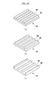
FIG. 10 (a), (b), and (c) are perspective views showing a groove type that is formed on a surface of a particulate sensor according to an exemplary embodiment of the present invention. - Referring to
FIG. 10 (a), (b), and (c) ,electrode portions 320 are formed on a front surface of thesensor 120 in a vertical direction with respect to the flow direction of the exhaust gas, andgrooves 800 are formed between theelectrode portions 320. - Further, the width and height of the
electrode portions 320 are 20 µm and the width between theelectrode portions 320 is 20 µm in (a), 40 µm in (b), and 60 µm in (c).
That is, the width of thegrooves 800 is 20 µm in (a), 40 µm in (b), and 60 µm in (c). -
FIG. 11 (a), (b), and (c) are perspective views showing different types of grooves are that is formed on a surface of a particulate sensor according to an exemplary embodiment of the present invention. - Referring to
FIG. 11 (a) ,electrode portions 320 having a width (w), a distance (s), and a height (h) are shown. - Here,
electrode portions 320 that are formed on a front side of thesensor 120 are continuously formed in a vertical direction with respect to the flow direction of the exhaust gas to be a furrow type. Here, a width (W) and a height (h) are 20 µm, and a distance (s) can be one of 20, 40, and 60 µm. - Referring to
FIG. 11 (b) ,electrode portions 320 having a predetermined width (w), distance (s), and height (h) are shown. - Each
electrode portion 320 that is formed on a front surface of thesensor 120 is a pillar type. Here, the width (W) and the height (h) are set to 20 µm, and the distance (s) can be set to one of 20, 40, and 60 µm. - Referring to
FIG. 11 (c) , anelectrode portion 320 having a predetermined width (w), distance (s), and height (h) is shown. - Each
electrode portion 320 that is formed on a front side of thesensor 120 is a pore type in which thepores 102 are sunken in a pillar type. - The width (W) and the height (h) are set to 20 µm, and the distance (s) can be set to one of 20, 40, and 60 µm.
-
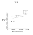
FIG. 12 is a graph showing a signal depending on types of grooves that are formed on a surface of a particulate sensor according to an exemplary embodiment of the present invention. - Referring to
FIG. 12 , a horizontal axis denotes a density (mg/m3) of particulate, and a vertical axis denotes a size of a signal that is generated depending on the type of sensor. - Here, the types of
sensors 120 include a furrow type, a pillar type, and a pore type that are described inFIG. 11 . As shown, the signal is large and meaningful for the furrow type. - Further, the width (W) and the distance (s) can be 10 µm, and the height (h) can be 40 µm.
-
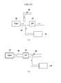
FIG. 13 is a schematic diagram of an exhaust system in which a sensor is disposed according to an exemplary embodiment of the present invention. - Referring to
FIG. 13 (a) and (b) , the exhaust system includes anengine 130, anexhaust line 100, adiesel particulate filter 132, asensor 120, and agas analyzer 134. - In
FIG. 13 (a) , the exhaust gas, before passing through thediesel particulate filter 132, is supplied to thesensor 120 and thegas analyzer 134. Accordingly, the characteristics of the exhaust gas before passing through thediesel particulate filter 132 are detected by thesensor 120 and thegas analyzer 134, and the signal characteristics of thesensor 120 can be analyzed. - In
FIG. 13 (b) , the exhaust gas that passes through thediesel particulate filter 132 is supplied to thegas analyzer 134 and thesensor 120. Accordingly, the characteristics of the exhaust gas that passes through thediesel particulate filter 132 can be detected by thesensor 120 and thegas analyzer 134, and the signal characteristics of thesensor 120 can be analyzed. -
FIG. 14 is a perspective view showing various types of surfaces of a particulate sensor according to an exemplary embodiment of the present invention. -
FIG. 14 (a) shows a pillar type of theelectrode portions 320, and aslanted surface 142 is formed on a side surface of the pillartype electrode portions 320. Theslanted surface 142 is formed such that the width of theelectrode portions 320 becomes narrow in a front end side. -
FIG. 14 (b) shows a sensor having a nanowire type ofelectrode portions 320, and the nanowire type ofelectrode portions 320 has a diameter (d) and a height (h), and a distance (s) is formed between them. -
FIG. 14 (c) shows a sensor having a furrow type ofelectrode portion 320, and the furrow type of electrode portion has a slantedsurface 142 on a side surface thereof. The section of theelectrode portion 320 has a trapezoidal shape with theslanted surface 142. -
FIG. 14(d) shows a sensor having a furrowtype electrode portion 320, and aslanted surface 142 is formed on a side surface of the furrowtype electrode portion 320. The section of theelectrode portion 320 has a triangle shape with theslanted surface 142. -
FIG. 14 (e) shows asensor 120 of a poretype electrode portion 320, and aslanted surface 142 is formed on an interior surface of apore type groove 102. The section of thegroove 102 has a trapezoidal shape with theslanted surface 142. - Here, the diameter (d) of the nanowire
type electrode portion 320 is shorter than 10 nm, which is a nanowire type. Also, a width (w) is 20 µm, a height (h) is longer than 20 µm, and a distance (s) can range from 20 to 120 µm. Further, the slant angle of the slantedsurface 142 can be one value that is selected from area ranging from 50 to 60 degrees (preferably 54.7 degrees). - In an exemplary embodiment of the present invention, the sensor is disposed at a downstream side of the diesel particulate filter, the sensor generates a charge signal with the particulate that is exhausted from the diesel particulate filter, and a control portion analyzes the size and the frequency of the charge signal that are generated and determines whether the diesel particulate filter is damaged or not.
- For convenience in explanation and accurate definition in the appended claims, the terms "upper", "lower", "inner" and "outer" are used to describe features of the exemplary embodiments with reference to the positions of such features as displayed in the figures.
- The foregoing descriptions of specific exemplary embodiments of the present invention have been presented for purposes of illustration and description. They are not intended to be exhaustive or to limit the invention to the precise forms disclosed, and obviously many modifications and variations are possible in light of the above teachings. They are not intended to be exhaustive or to limit the invention to the precise forms disclosed, and obviously many modifications and variations are possible in light of the above teachings as well as various alternatives and modifications thereof. It is intended that the scope of the invention be defined by the Claims appended hereto and their equivalents.
Claims (15)
- A particulate sensor apparatus, comprising:an exhaust line through which exhaust gas flows; anda sensor that is disposed at one side in the exhaust line and generates electrical charges when a particulate passes near vicinity of the sensor,wherein an electrode portion is formed on a front surface of the sensor facing the particulate.
- The particulate sensor apparatus of claim 1, wherein a groove is formed between electrode portions in a direction that crosses a direction that the exhaust gas flows.
- The particulate sensor apparatus of claim 2, wherein the electrode portions are formed perpendicular to a direction that the exhaust gas flows.
- The particulate sensor apparatus of claim 2, wherein a cross section of the electrode portion is in a rectangular shape.
- The particulate sensor apparatus of claim 2, wherein a slanted surface is formed to a lateral side of the electrode portions from an upper end surface thereof to the groove.
- The particulate sensor apparatus of claim 5, wherein the slanted surface forms an angle ranging from 50 to 60 degrees with respect to the upper end surface of the electrode portions.
- The particulate sensor apparatus of claim 5, wherein- a cross section of the electrode portion is in a trapezoidal shape formed with the slanted surface, or- a cross section of the electrode portion is in a triangular shape formed with the slanted surface.
- The particulate sensor apparatus of claim 1, wherein the electrode portion is in a pillar shape that protrudes at the front surface of the sensor in the pillar shape.
- The particulate sensor apparatus of claim 8, wherein the electrode portion has a width of the electrode portion that is 20 nm, a distance from an adjacent electrode portion that ranges from 20 to 120 nm, and a height thereof that ranges from 20 nm to hundreds of nanometers.
- The particulate sensor apparatus of claim 8, wherein a slanted surface is formed on lateral sides of the protrude portion to become wider from an upper end surface thereof to the front surface.
- The particulate sensor apparatus of claim 9, wherein a cross-section of the electrode portion- has a trapezoidal shape, or- is in a triangular shape.
- The particulate sensor apparatus of claim 1, wherein the electrode portion protrudes in the pillar shape, and an exterior diameter thereof is less than 10 nm to be a nano-wire shape.
- The particulate sensor apparatus of claim 1, wherein the electrode portion is formed with pores that are sunken in a pillar shape.
- The particulate sensor apparatus of claim 13, wherein the pores have- a cuboidal shape, or- a trapezoidal shape to become narrower from an upper surface thereof to a lower surface thereof.
- The particulate sensor apparatus of claim 1, wherein a diesel particulate filter (DPF) is disposed at an upstream side of the sensor, the sensor generates the electrical charge that is induced by the particulate included in the exhaust gas, and a control portion determines whether the diesel particulate filter is damaged or not depending on the electrical charge of the sensor.
Applications Claiming Priority (1)
| Application Number | Priority Date | Filing Date | Title |
|---|---|---|---|
| KR1020120119183A KR101461873B1 (en) | 2012-10-25 | 2012-10-25 | Particulate matters sensor unit |
Publications (2)
| Publication Number | Publication Date |
|---|---|
| EP2725339A2 true EP2725339A2 (en) | 2014-04-30 |
| EP2725339A3 EP2725339A3 (en) | 2018-01-10 |
Family
ID=47747300
Family Applications (1)
| Application Number | Title | Priority Date | Filing Date |
|---|---|---|---|
| EP12199713.4A Withdrawn EP2725339A3 (en) | 2012-10-25 | 2012-12-28 | Particulate matter sensor unit |
Country Status (5)
| Country | Link |
|---|---|
| US (2) | US20140116113A1 (en) |
| EP (1) | EP2725339A3 (en) |
| JP (1) | JP6049444B2 (en) |
| KR (1) | KR101461873B1 (en) |
| CN (1) | CN103776752B (en) |
Cited By (2)
| Publication number | Priority date | Publication date | Assignee | Title |
|---|---|---|---|---|
| EP2743672A2 (en) * | 2012-12-17 | 2014-06-18 | Hyundai Motor Company | Particulate matter sensor unit |
| EP3382379A4 (en) * | 2015-11-25 | 2019-08-14 | Kyocera Corporation | SENSOR SUBSTRATE AND SENSOR DEVICE |
Families Citing this family (7)
| Publication number | Priority date | Publication date | Assignee | Title |
|---|---|---|---|---|
| KR101610167B1 (en) | 2014-12-02 | 2016-04-08 | 현대자동차 주식회사 | Particulate matter sensor |
| RU2707983C2 (en) * | 2015-02-17 | 2019-12-03 | Форд Глобал Текнолоджиз, Ллк | System (embodiments) and method of measuring parameters of solid particles |
| KR20160149898A (en) | 2015-06-19 | 2016-12-28 | 현대자동차주식회사 | Particulate matter sensor |
| KR101755469B1 (en) * | 2015-12-08 | 2017-07-07 | 현대자동차 주식회사 | Particleate matter detection sensor |
| KR101724499B1 (en) * | 2015-12-11 | 2017-04-07 | 현대자동차 주식회사 | Particulate matter sensor and measurement method thereof |
| US20180073973A1 (en) | 2016-09-12 | 2018-03-15 | Hyundai Motor Company | Particulate matters sensor device and manufacturing method of sensor unit provided in this |
| KR20180065318A (en) * | 2016-12-07 | 2018-06-18 | 현대자동차주식회사 | Chip type sensor for measuring particulate matter |
Family Cites Families (13)
| Publication number | Priority date | Publication date | Assignee | Title |
|---|---|---|---|---|
| US6495892B2 (en) * | 1997-08-08 | 2002-12-17 | California Institute Of Technology | Techniques and systems for analyte detection |
| JP2002022703A (en) * | 2000-07-06 | 2002-01-23 | Kansai Ootomeishiyon Kk | Powder concentration measurement device |
| JP2002365263A (en) * | 2001-06-06 | 2002-12-18 | Mitsubishi Chemicals Corp | Powder concentration detector |
| JP2005010083A (en) * | 2003-06-20 | 2005-01-13 | Sharp Corp | Particle detection sensor and particle detection measurement apparatus using the same. |
| US7765792B2 (en) * | 2005-10-21 | 2010-08-03 | Honeywell International Inc. | System for particulate matter sensor signal processing |
| KR100946701B1 (en) * | 2007-12-10 | 2010-03-12 | 한국전자통신연구원 | Nanocrystalline composite oxide thin film, environmental gas sensor and environmental gas sensor manufacturing method including the same |
| US8176768B2 (en) * | 2008-07-04 | 2012-05-15 | Ngk Insulators, Ltd. | Particulate matter detection device |
| JP2011080781A (en) * | 2009-10-05 | 2011-04-21 | Nippon Soken Inc | Particulate sensing element and particulate sensor using the same |
| JP2011080926A (en) * | 2009-10-09 | 2011-04-21 | Denso Corp | Particulate detection element |
| JP5635776B2 (en) * | 2010-01-07 | 2014-12-03 | 日本碍子株式会社 | Particulate matter detection device and inspection method for particulate matter detection device |
| JP2011247650A (en) * | 2010-05-24 | 2011-12-08 | Denso Corp | Particulate matter detection sensor, and particulate matter detection sensor unit |
| JP5542006B2 (en) * | 2010-08-26 | 2014-07-09 | 日本碍子株式会社 | Particulate matter detector |
| JP5201194B2 (en) * | 2010-10-28 | 2013-06-05 | 株式会社デンソー | Particulate matter detection device and method for manufacturing particulate matter detection element |
-
2012
- 2012-10-25 KR KR1020120119183A patent/KR101461873B1/en not_active Expired - Fee Related
- 2012-12-26 JP JP2012282436A patent/JP6049444B2/en not_active Expired - Fee Related
- 2012-12-28 CN CN201210587262.3A patent/CN103776752B/en not_active Expired - Fee Related
- 2012-12-28 EP EP12199713.4A patent/EP2725339A3/en not_active Withdrawn
- 2012-12-31 US US13/731,704 patent/US20140116113A1/en not_active Abandoned
-
2015
- 2015-05-18 US US14/715,270 patent/US20150316448A1/en not_active Abandoned
Non-Patent Citations (1)
| Title |
|---|
| None |
Cited By (3)
| Publication number | Priority date | Publication date | Assignee | Title |
|---|---|---|---|---|
| EP2743672A2 (en) * | 2012-12-17 | 2014-06-18 | Hyundai Motor Company | Particulate matter sensor unit |
| EP3382379A4 (en) * | 2015-11-25 | 2019-08-14 | Kyocera Corporation | SENSOR SUBSTRATE AND SENSOR DEVICE |
| US10768131B2 (en) | 2015-11-25 | 2020-09-08 | Kyocera Corporation | Sensor substrate arrangement for a particulate sensor device |
Also Published As
| Publication number | Publication date |
|---|---|
| JP6049444B2 (en) | 2016-12-21 |
| US20140116113A1 (en) | 2014-05-01 |
| KR101461873B1 (en) | 2014-11-20 |
| CN103776752A (en) | 2014-05-07 |
| CN103776752B (en) | 2018-05-25 |
| US20150316448A1 (en) | 2015-11-05 |
| KR20140052720A (en) | 2014-05-07 |
| EP2725339A3 (en) | 2018-01-10 |
| JP2014084862A (en) | 2014-05-12 |
Similar Documents
| Publication | Publication Date | Title |
|---|---|---|
| US20140116113A1 (en) | Particulate matter sensor unit | |
| US9759675B2 (en) | Particulate matter sensor unit | |
| US6469524B1 (en) | System and method for interrogating a capacitive sensor | |
| George et al. | A combined inductive–capacitive proximity sensor for seat occupancy detection | |
| EP2846143B1 (en) | Pressure sensor | |
| CN104428741B (en) | Capacitive touchscreen with height determination | |
| US20080282769A1 (en) | Apparatus and method for shielding a soot sensor | |
| US8666679B2 (en) | Micro-fabricated double condenser method and apparatus for the measurement of number-size distribution of airborne nano-particles | |
| CN102918381B (en) | Method and particle sensor for detecting particles in an exhaust gas stream | |
| CN102725183A (en) | Occupant detection and classification system | |
| JP5333675B2 (en) | Particulate matter treatment equipment | |
| EP2141482A1 (en) | Particulate matter detection device | |
| CN107631966B (en) | Method and system for exhaust particulate matter sensing | |
| US10690580B2 (en) | Sensor for detecting particles | |
| JP2009278319A (en) | Capacitance proximity sensor | |
| US9354196B2 (en) | Particulate matter sensor unit | |
| EP3690913A1 (en) | Operation input device and door handle | |
| US8899028B2 (en) | Particulate matter processing apparatus | |
| JPH11242052A (en) | Semiconductor acceleration sensor | |
| JP4170112B2 (en) | Obstacle discrimination device for vehicle | |
| JP5102716B2 (en) | Capacitive proximity sensor | |
| CN110998282A (en) | Particle sensor and operating method for the same | |
| JP2008096322A (en) | Particle classifier | |
| JP2012220220A (en) | Liquid level detection device | |
| CN103575451A (en) | Sensor means and method for determining pressure of medium, and method of manufacturing sensor means |
Legal Events
| Date | Code | Title | Description |
|---|---|---|---|
| PUAI | Public reference made under article 153(3) epc to a published international application that has entered the european phase |
Free format text: ORIGINAL CODE: 0009012 |
|
| 17P | Request for examination filed |
Effective date: 20121228 |
|
| AK | Designated contracting states |
Kind code of ref document: A2 Designated state(s): AL AT BE BG CH CY CZ DE DK EE ES FI FR GB GR HR HU IE IS IT LI LT LU LV MC MK MT NL NO PL PT RO RS SE SI SK SM TR |
|
| AX | Request for extension of the european patent |
Extension state: BA ME |
|
| PUAL | Search report despatched |
Free format text: ORIGINAL CODE: 0009013 |
|
| AK | Designated contracting states |
Kind code of ref document: A3 Designated state(s): AL AT BE BG CH CY CZ DE DK EE ES FI FR GB GR HR HU IE IS IT LI LT LU LV MC MK MT NL NO PL PT RO RS SE SI SK SM TR |
|
| AX | Request for extension of the european patent |
Extension state: BA ME |
|
| RIC1 | Information provided on ipc code assigned before grant |
Ipc: G01N 15/06 20060101AFI20171204BHEP |
|
| STAA | Information on the status of an ep patent application or granted ep patent |
Free format text: STATUS: THE APPLICATION IS DEEMED TO BE WITHDRAWN |
|
| 18D | Application deemed to be withdrawn |
Effective date: 20180711 |