EP2725222B1 - Systems and methods for use in operating power generation systems - Google Patents
Systems and methods for use in operating power generation systems Download PDFInfo
- Publication number
- EP2725222B1 EP2725222B1 EP13189117.8A EP13189117A EP2725222B1 EP 2725222 B1 EP2725222 B1 EP 2725222B1 EP 13189117 A EP13189117 A EP 13189117A EP 2725222 B1 EP2725222 B1 EP 2725222B1
- Authority
- EP
- European Patent Office
- Prior art keywords
- pitch
- controller
- signal
- turbine
- pitch controller
- Prior art date
- Legal status (The legal status is an assumption and is not a legal conclusion. Google has not performed a legal analysis and makes no representation as to the accuracy of the status listed.)
- Not-in-force
Links
- 238000000034 method Methods 0.000 title claims description 33
- 238000010248 power generation Methods 0.000 title claims description 29
- 238000004891 communication Methods 0.000 claims description 60
- 230000004044 response Effects 0.000 claims description 7
- 230000002411 adverse Effects 0.000 description 7
- 230000006870 function Effects 0.000 description 6
- 230000005611 electricity Effects 0.000 description 4
- 239000004020 conductor Substances 0.000 description 2
- 230000008569 process Effects 0.000 description 2
- 230000003416 augmentation Effects 0.000 description 1
- 230000005465 channeling Effects 0.000 description 1
- 238000010276 construction Methods 0.000 description 1
- 230000007547 defect Effects 0.000 description 1
- 230000003111 delayed effect Effects 0.000 description 1
- 238000010586 diagram Methods 0.000 description 1
- 230000000694 effects Effects 0.000 description 1
- 230000007257 malfunction Effects 0.000 description 1
- 238000005457 optimization Methods 0.000 description 1
- 230000008520 organization Effects 0.000 description 1
- 230000000737 periodic effect Effects 0.000 description 1
- 230000009467 reduction Effects 0.000 description 1
- 230000001131 transforming effect Effects 0.000 description 1
Images
Classifications
-
- F—MECHANICAL ENGINEERING; LIGHTING; HEATING; WEAPONS; BLASTING
- F03—MACHINES OR ENGINES FOR LIQUIDS; WIND, SPRING, OR WEIGHT MOTORS; PRODUCING MECHANICAL POWER OR A REACTIVE PROPULSIVE THRUST, NOT OTHERWISE PROVIDED FOR
- F03D—WIND MOTORS
- F03D7/00—Controlling wind motors
- F03D7/02—Controlling wind motors the wind motors having rotation axis substantially parallel to the air flow entering the rotor
- F03D7/022—Adjusting aerodynamic properties of the blades
- F03D7/0224—Adjusting blade pitch
-
- F—MECHANICAL ENGINEERING; LIGHTING; HEATING; WEAPONS; BLASTING
- F03—MACHINES OR ENGINES FOR LIQUIDS; WIND, SPRING, OR WEIGHT MOTORS; PRODUCING MECHANICAL POWER OR A REACTIVE PROPULSIVE THRUST, NOT OTHERWISE PROVIDED FOR
- F03D—WIND MOTORS
- F03D7/00—Controlling wind motors
- F03D7/02—Controlling wind motors the wind motors having rotation axis substantially parallel to the air flow entering the rotor
- F03D7/0264—Controlling wind motors the wind motors having rotation axis substantially parallel to the air flow entering the rotor for stopping; controlling in emergency situations
-
- F—MECHANICAL ENGINEERING; LIGHTING; HEATING; WEAPONS; BLASTING
- F03—MACHINES OR ENGINES FOR LIQUIDS; WIND, SPRING, OR WEIGHT MOTORS; PRODUCING MECHANICAL POWER OR A REACTIVE PROPULSIVE THRUST, NOT OTHERWISE PROVIDED FOR
- F03D—WIND MOTORS
- F03D7/00—Controlling wind motors
- F03D7/02—Controlling wind motors the wind motors having rotation axis substantially parallel to the air flow entering the rotor
- F03D7/04—Automatic control; Regulation
- F03D7/042—Automatic control; Regulation by means of an electrical or electronic controller
- F03D7/047—Automatic control; Regulation by means of an electrical or electronic controller characterised by the controller architecture, e.g. multiple processors or data communications
-
- F—MECHANICAL ENGINEERING; LIGHTING; HEATING; WEAPONS; BLASTING
- F05—INDEXING SCHEMES RELATING TO ENGINES OR PUMPS IN VARIOUS SUBCLASSES OF CLASSES F01-F04
- F05B—INDEXING SCHEME RELATING TO WIND, SPRING, WEIGHT, INERTIA OR LIKE MOTORS, TO MACHINES OR ENGINES FOR LIQUIDS COVERED BY SUBCLASSES F03B, F03D AND F03G
- F05B2260/00—Function
- F05B2260/845—Redundancy
-
- F—MECHANICAL ENGINEERING; LIGHTING; HEATING; WEAPONS; BLASTING
- F05—INDEXING SCHEMES RELATING TO ENGINES OR PUMPS IN VARIOUS SUBCLASSES OF CLASSES F01-F04
- F05B—INDEXING SCHEME RELATING TO WIND, SPRING, WEIGHT, INERTIA OR LIKE MOTORS, TO MACHINES OR ENGINES FOR LIQUIDS COVERED BY SUBCLASSES F03B, F03D AND F03G
- F05B2270/00—Control
- F05B2270/10—Purpose of the control system
- F05B2270/107—Purpose of the control system to cope with emergencies
- F05B2270/1074—Purpose of the control system to cope with emergencies by using back-up controls
-
- Y—GENERAL TAGGING OF NEW TECHNOLOGICAL DEVELOPMENTS; GENERAL TAGGING OF CROSS-SECTIONAL TECHNOLOGIES SPANNING OVER SEVERAL SECTIONS OF THE IPC; TECHNICAL SUBJECTS COVERED BY FORMER USPC CROSS-REFERENCE ART COLLECTIONS [XRACs] AND DIGESTS
- Y02—TECHNOLOGIES OR APPLICATIONS FOR MITIGATION OR ADAPTATION AGAINST CLIMATE CHANGE
- Y02E—REDUCTION OF GREENHOUSE GAS [GHG] EMISSIONS, RELATED TO ENERGY GENERATION, TRANSMISSION OR DISTRIBUTION
- Y02E10/00—Energy generation through renewable energy sources
- Y02E10/70—Wind energy
- Y02E10/72—Wind turbines with rotation axis in wind direction
Definitions
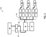
- Fig. 2 illustrates an exemplary control system 30 that may be used with power generation system 10 (shown in Fig. 1 ).
- control system 30 includes components housed within hub 16 (shown in Fig. 1 ), nacelle 14 (shown in Fig. 1 ), blades 18 (shown in Fig. 1 ), and/or tower 12 (shown in Fig. 1 ). More specifically, in the exemplary embodiment, control system 30 includes a first or primary pitch controller 40 that is housed within hub 16 and that controls, for example, a pitch angle (not shown) and/or a relative position (not shown) of blades 18. In the exemplary embodiment, pitch controller 40 includes a microprocessor.
- pitch controller 40 communicates with motor drive 42 and/or motor 43 via a communication network 50.
- Each motor drive 42 and motor 43 is coupled to at least one backup battery 64.
- Each backup battery 64 may include a battery (not shown) that provides backup electrical power to components within hub 16, nacelle 14, and tower 12 components in the event of, for example, a communication loss.
- each backup battery 64 includes a communication module (not shown) that is coupled to pitch controllers 40 and 44 and/or to turbine controller 60 such that each backup battery 64 may communicate with pitch controllers 40 and 44 and/or turbine controller 60 via a communication network 54.
- each backup battery 64 may transmit a charge status of each respective battery to turbine controller 60.
- turbine controller 60 may transmit signals via any other suitable method that enables power generation system 10 and/or control system 30 to function as described herein. For example, in one embodiment, turbine controller 60 may determine which pitch controller to use based on communication issues and/or feedback signals that turbine controller 60 receives.
- control system 30 may have each motor drive 42 initially receiving signals from back-up pitch controller 44 such that back-up pitch controller 44 is implementing the pitch control commands by transmitting signals to each motor drive 42.
- control system 30 relies at least partially upon communication network 52 for communication between turbine controller 60 and back-up pitch controller 44.
- communication network 52 is error-prone, or if one or more components of back-up pitch controller 44 and/or of turbine controller 60 are error-prone or faulty, a loss of communication between turbine controller 60 and back-up pitch controller 44 and/or a loss of communication between back-up pitch controller 44 and each motor drive 42 may result.
- back-up pitch controller 44 is unable to implement the pitch control commands.
- control system that substantially prevents the operating life of the turbine from being adversely effected.
- the control system includes a first or primary pitch controller, and a secondary or back-up pitch controller that each implements pitch control commands for the turbine blades. More specifically, the exemplary control system includes a turbine controller that transmits signals representative of pitch control commands to both the main and back-up pitch controllers.
Description
- The field of the invention relates generally to power generation systems and, more particularly, to systems and methods for use in operating power generation systems.
- At least some known power generation systems include turbines, such as wind turbines, to generate power. For example, at least some known wind turbines convert the kinetic energy of wind into electrical energy. Known wind turbines include one or more blades that rotate when wind strikes the blades. The flow of wind over each turbine blade generates a lift, induces rotation, and provides a torque to generate power.
- At least some known wind turbines include at least one control system, such as a pitch control system. The pitch control system may include a plurality of controllers that communicate with each other to control components of the wind turbine. One type of controller is a pitch controller, and at least some known wind turbines includes a plurality of pitch controllers that are each coupled to a respective blade to enable changes in a pitch angle of the respective blade. More specifically, to facilitate enhanced operation, each pitch controller may drive a respective blade to a desired operating pitch angle based on existing wind conditions and/or in response to a desired power generation. Each pitch controller may also rotate a respective blade to a non-operating or feathered position to facilitate reducing the amount of lift induced to the blades from the wind. The blades may also be feathered to prevent damage to the wind turbine, for example, during high wind conditions or during wind turbine fault conditions.
- Another type of controller is a turbine controller that may function as a master controller for the wind turbine system. For example, a known turbine controller may control each pitch controller. In such configurations, the turbine controller issues commands or control messages to each pitch controller, and, in response, the pitch controllers implement these commands or control messages on respective blades. For example, the turbine controller may issue commands to each pitch controller to rotate respective blades to a defined position.
- However, known pitch controllers and the turbine controller may suffer periodic losses of communication with each other. Moreover, known pitch controllers and/or the turbine controller may incur a malfunction or have a defect when at least one of the controllers is inoperable. Such communication losses and/or inoperability of one of the controllers may cause undesirable consequences. For example, when a loss of communication occurs between just one pitch controller and the turbine controller, and/or when just one of the components is inoperable, known wind turbines may enter a fault state in which a hard-braking procedure is implemented and all associated rotor blades are stopped via mechanical braking and/or through battery-driven braking procedures. For example, mechanical braking may be applied to the turbine that is stopped and the blades may be stopped by feathering the blades (i.e., blades out of the wind). Such procedures may induce an undesirable amount of loading upon the wind turbine system and over time, may reduce the operating life of the wind turbine. In addition to undesired loading of the turbine and corresponding structure, the emergency braking also adversely impacts turbine availability thus reducing power generation (i.e., value of the wind turbine).
-
WO 2012/061953 describes a system for operating a wind turbine during a fault, including a pitch motor for rotating each rotor blade, second pitch sensors for determining when the rotor blade is rotated to a set point, and a backup pitch controller. After a fault is detected, it is determined whether the wind speed in the vicinity of the wind turbine is less than or greater than or equal to a maximum rated velocity of the wind turbine. The backup pitch controller then rotates the rotor blades to a specific set point based on the determination.EP 1860321 describes a turbine with a multiple pitch control systems and differing systems to power these pitch control systems so as to move wind turbine blades to a parked, feathered position in the event of a loss of main power.WO 2012/130246 A1 discloses generic redundant control architectures in a wind turbine. The invention resides in a control system, a power generation system and a method for operating a power generation system as defined in the appended claims. -
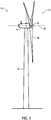
Fig. 1 is a side view schematic of an exemplary power generation system; and -
Fig. 2 is a block diagram of an exemplary control system that may be used with the power generation system shown inFig. 1 . - The exemplary systems and methods described herein overcome at least some known disadvantages associated with at least some known power generation systems that use turbines, such as wind turbines. The embodiments described herein include a control system that includes a first or primary pitch controller, and a secondary or back-up pitch controller that each implements pitch control commands for the same turbine blades. More specifically, the exemplary control system includes a turbine controller that transmits signals representative of pitch control commands to both the main and back-up pitch controllers. As such, while the main pitch controller may transmit signal(s) of pitch control commands to a plurality of motor drives to pitch the turbine blades, the back-up pitch controller may also be able to transmit signal(s) of the pitch control commands to the motor drives when the main pitch controller is inoperable and/or is unable to communicate with the motor drives. As a result, the power generation system will continue to operate as the turbine is substantially prevented from entering a fault state in which an emergency or hard-braking procedure is implemented. Accordingly, an undesirable amount of loading upon the turbine is substantially prevented and the operating life of the turbine is not adversely effected. In addition, because the emergency braking procedure is prevented from being implemented, turbine availability is not adversely effected and power generation may not be reduced.
-
Fig. 1 illustrates an exemplarypower generation system 10 that includes aturbine 11. More specifically, in the exemplary embodiment,turbine 11 is a wind turbine. Although the exemplary embodiment illustrates a power generation system, the present disclosure is not limited to power generation systems, and one of ordinary skill in the art will appreciate that the current disclosure may be used in connection with any other type of system. Moreover, while the exemplary embodiment includes a wind turbine, the present invention is not limited to any one particular type of turbine, and one of ordinary skill in the art will appreciate that the current disclosure may be used in connection with other turbine systems. - In the exemplary embodiment,
wind turbine 11 includes atower 12, anacelle 14 coupled totower 12, ahub 16 coupled tonacelle 14, and at least oneblade 18 that is coupled tohub 16. More specifically, in the exemplary embodiment,wind turbine 11 includes threeblades 18. Alternatively,wind turbine 11 may include any number of blades that enablespower generation system 10 to function as described herein. In the exemplary embodiment,tower 12 is configured to provide support fornacelle 14,hub 16, andblade 18.Tower 12 may be of any suitable height and construction as is known in the art and that enablespower generation system 10 to function as described herein. It should be noted that, as used herein, the term "couple" is not limited to a direct mechanical, thermal, communication, and/or an electrical connection between components, but may also include an indirect mechanical, thermal, communication and/or electrical connection between multiple components. -
Nacelle 14 is coupled totower 12 andnacelle 14 houses components (not shown) that are used for transforming rotational energy provided byblades 18 into electricity.Nacelle 14 may be constructed by any suitable method that is known in the art. In the exemplary embodiment,hub 16 is coupled tonacelle 14 to provide a rotatable housing for at least oneblade 18.Hub 16 may be constructed by any suitable method that is known in the art. - In the exemplary embodiment,
blades 18 are also coupled tohub 16, such that eachblade 18 is rotatable about an axis ofrotation 22 when wind strikesblades 18. In the exemplary embodiment, eachblade 18 is oriented substantially perpendicularly with respect to the ground. Moreover, eachblade 18 rotates through substantially the same plane of rotation and each is substantially parallel to a centerline axis 20 oftower 12. Eachblade 18 may be constructed by any suitable method that is known in the art. In the exemplary embodiment, a control system (not shown inFig. 1 ) is coupled toturbine 11. More specifically, in the exemplary embodiment, the control system is a pitch control system forturbine 11. - During operation, as wind strikes
blades 18,blades 18 rotate abouthub 16, and the kinetic energy of the wind is transformed into rotational energy byblades 18. More specifically, a rotation ofblades 18 rotates a gearbox (not shown) withinnacelle 14. A generator (not shown) housed withinnacelle 14 generates electricity. The cable assembly may deliver the electricity to a power grid (not shown) or other destination. As described in more detail below, during operation ofwind turbine 11, the control system operatespower generation system 10 by controlling turbine pitch such thatturbine 11 is substantially prevented from entering a fault state in which a hard braking procedure is implemented. As such, an undesirable amount of loading induced uponwind turbine 11 is substantially prevented and the operating life ofturbine 11 may not be adversely effected. In addition, because the emergency braking procedure is prevented from being implemented,turbine 11 availability is not adversely effected and power generation may not be reduced. -
Fig. 2 illustrates anexemplary control system 30 that may be used with power generation system 10 (shown inFig. 1 ). In the exemplary embodiment,control system 30 includes components housed within hub 16 (shown inFig. 1 ), nacelle 14 (shown inFig. 1 ), blades 18 (shown inFig. 1 ), and/or tower 12 (shown inFig. 1 ). More specifically, in the exemplary embodiment,control system 30 includes a first orprimary pitch controller 40 that is housed withinhub 16 and that controls, for example, a pitch angle (not shown) and/or a relative position (not shown) ofblades 18. In the exemplary embodiment,pitch controller 40 includes a microprocessor. In an alternative embodiment,pitch controller 40 may include a programmable logic controller (PLC), a microcontroller, a field programmable gate array (FPGA) or any other suitable programmable circuit that enablespitch controller 40 to operate as described herein. As used herein, the term "control" includes, but is not limited to only, issuing commands to be implemented by exercising oversight and supervision of, and/or directing operation of, one or more subject components. The term "control" also includes a regulation-type of control, e.g. a feedback-loop regulation. -
Primary pitch controller 40 is coupled to at least one pitch ormotor drive 42. More specifically, in the exemplary embodiment,primary pitch controller 40 is coupled to threemotor drives 42, and eachmotor drive 42 is coupled to arespective motor 43. In the exemplary embodiment, threemotors 43 are illustrated, wherein eachmotor 43 is coupled to oneblade 18 such that eachmotor 43 may rotaterespective blade 18 using, for example, hydraulic, electric, or gear-driven means. Alternatively,control system 30 may include any suitable number ofmotors 43. -
Primary pitch controller 40 is coupled to eachblade 18 through arespective motor drive 42 and through arespective motor 43, such thatprimary pitch controller 40 can selectively transmit signal(s) tomotor drive 42 and/or tomotor 43. For example,primary pitch controller 40 may selectively transmit a signal tomotor 43 such that power from amotor drive 42 orbackup batteries 64 may operatemotor 43. Various connections are available betweenprimary pitch controller 40 andmotor drive 42 and/ormotor 43. Such connections may include, without limitation, an electrical conductor, a low-level serial data connection, such as Recommended Standard (RS) 232 or RS-485, a high-level serial data connection, such as Universal Serial Bus (USB), CAN and Ethernet Global Data (EGD), a field bus, a process field bus (PROFIBUS®), or Institute of Electrical and Electronics Engineers (IEEE®) 1394, a parallel data connection, such as IEEE® 1284 or IEEE® 488, a short-range wireless communication channel such as BLUETOOTH®, and/or a private (e.g., inaccessible outside power generation system 10) network connection, whether wired or wireless. IEEE is a registered trademark of the Institute of Electrical and Electronics Engineers, Inc., of New York, New York. BLUETOOTH is a registered trademark of Bluetooth SIG, Inc. of Kirkland, Washington. PROFIBUS is a registered trademark of Profibus Trade Organization of Scottsdale, Arizona. For example, in the exemplary embodiment,pitch controller 40 communicates withmotor drive 42 and/ormotor 43 via acommunication network 50. - In the exemplary embodiment,
control system 30 includes a secondary or back-uppitch controller 44 that is also housed withinhub 16 and that also controls, for example, the pitch angle and/or the relative position ofblades 18. In the exemplary embodiment, back-uppitch controller 44 includes a microprocessor. In an alternative embodiment, back-uppitch controller 44 may include a FPGA, a microcontroller, a PLC or any other suitable programmable circuit that enablespitch controller 40 to operate as described herein. - Back-
up pitch controller 44 is coupled toprimary pitch controller 40. In addition, back-uppitch controller 44 is also coupled to eachblade 18 through arespective motor drive 42 and through arespective motor 43 such that back-uppitch controller 44 can selectively transmit signal(s) tomotor drive 42 and/ormotor 43. Various connections are available between back-uppitch controller 44 andmotor drive 42 and/ormotor 43. Such connections may include, without limitation, an electrical conductor, a low-level serial data connection, such as RS-232 or RS-485, a high-level serial data connection, such as USB, a field bus, a PROFIBUS®, or IEEE® 1394, a parallel data connection, such as IEEE® 1284 or IEEE® 488, a short-range wireless communication channel such as BLUETOOTH®, and/or a private (e.g., inaccessible outside power generation system 10) network connection, whether wired or wireless. For example, in the exemplary embodiment, back-uppitch controller 44 communicates withmotor drive 42 and/ormotor 43 via acommunication network 52. -
Control system 30 also includes aturbine controller 60 that is housed withintower 12. Alternatively,turbine controller 60 may be located within another portion ofturbine 11, such asnacelle 14.Turbine controller 60 is coupled toprimary pitch controller 40 and to back-uppitch controller 44. Moreover, in the exemplary embodiment,turbine controller 60 is configured to operate as a master controller ofturbine 11 and ofcontrol system 30, and may include a computer or other processor configured to execute control algorithms. As used herein, the term "processor" includes any programmable system including systems and microcontrollers, reduced instruction set circuits (RISC), application specific integrated circuits (ASIC), PLC, and any other circuit capable of executing the functions described herein. The above examples are exemplary only, and thus are not intended to limit in any way the definition and/or meaning of the term processor. -
Turbine controller 60 may control other controllers ofturbine 11 by transmitting signals to the other controllers via a communication network. For example,turbine controller 60 may controlpitch controllers controllers communication networks Turbine controller 60 may also communicate with other wind turbines (not shown) and/or a wind farm management system (not shown), and perform error handling and operational optimization. Moreover,turbine controller 60 may execute a SCADA (Supervisory, Control and Data Acquisition) program. -
Control system 30 also includes aconnection device 61 that is coupled toturbine controller 60 and to pitchcontrollers connection device 61 is a slip ring that enables communication betweenturbine controller 60 andpitch controllers communication networks connection device 61 to facilitate channeling or transmitting signals fromturbine controller 60 torespective pitch controllers - Each
motor drive 42 andmotor 43, in the exemplary embodiment, is coupled to at least onebackup battery 64. Eachbackup battery 64 may include a battery (not shown) that provides backup electrical power to components withinhub 16,nacelle 14, andtower 12 components in the event of, for example, a communication loss. Moreover, in the exemplary embodiment, eachbackup battery 64 includes a communication module (not shown) that is coupled to pitchcontrollers turbine controller 60 such that eachbackup battery 64 may communicate withpitch controllers turbine controller 60 via acommunication network 54. For example, eachbackup battery 64 may transmit a charge status of each respective battery toturbine controller 60. - Moreover,
nacelle 14 may include a brake (not shown) and a gearbox (not shown). For example, the gearbox may enable an augmentation of a rotation of a main rotor shaft (not shown) driven by the rotation ofblades 18 to increase the speed of a generator (not shown). The brake may provide emergency stopping power to the generator and/or to turbine operation in an event of a fault or other error condition. For example,turbine controller 60 may transmit a signal to use the brake to pitchcontrollers Pitch controllers motors 43 viacommunication network 54. - During operation, rotation of
blades 18 causes rotation of the main rotor shaft, resulting in electricity being produced by the generator.Turbine controller 60 monitors the rotational speed and loading ofblades 18 using, for example, blade and/or hub sensors (not shown). When the wind speed exceeds a rated speed ofturbine 11, for example,turbine controller 60 may generate signal(s) that are representative of pitch control commands forblades 18 and transmits the signal(s) tocontrollers turbine controller 60 generates at least two signals that are each representative of the same pitch control command to increase or decrease the pitch angle ofblades 18 as necessary to facilitate reducing or increasing the lift induced toblades 18 by the wind.Turbine controller 60 transmits one signal toprimary pitch controller 40 viacommunication network 50 and the other signal to back-uppitch controller 44 viacommunication network 52.Turbine controller 60 may transmit both signals simultaneously to eachpitch controller turbine controller 60 may transmit each signal at different times to eachpitch controller primary pitch controller 40 may receive a signal before back-uppitch controller 44. - When
primary pitch controller 40 receives the signal representative of the pitch control command,primary pitch controller 40 implements the pitch control command by transmitting signals to eachmotor drive 42 in analog form or in digital form. When eachmotor drive 42 receives a signal, eachmotor drive 42 processes the signal. For example, eachmotor drive 42 may convert the signal in analog or digital form to a power signal. Eachmotor drive 42 can then transmit the power signal torespective motors 43 such that eachmotor 43 may powerrespective blades 18 to rotateblades 18 by an amount specified in the pitch control command. For example,blades 18 may be rotated to a pitch angle specified byprimary pitch controller 40. - In the exemplary embodiment,
control system 30 relies at least partially uponcommunication network 50 for communication betweenturbine controller 60 andprimary pitch controller 40. However, ifcommunication network 50 is error-prone, or if one or more components ofprimary pitch controller 40 and/or ofturbine controller 60 are error-prone or faulty, a loss of communication betweenturbine controller 60 andprimary pitch controller 40 and/or a loss of communication betweenprimary pitch controller 40 and eachmotor drive 42 may result. Accordingly,primary pitch controller 40 is unable to implement the pitch control command. As used herein, the term "communication loss" includes unreliable or broken data and/or control communication conditions between the respective components, and also includes communication failures, such as for example, due to hardware failure, software failure, and/or network failure, and unstable communication between the components. - For example, a communication loss may result from one or more lost or corrupted signals or packets of data from
communication networks communication networks pitch controllers turbine controller 60, and/or in any other component used incommunication networks - When
primary pitch controller 40 is unable to implement the pitch control command,control system 30 utilizes back-uppitch controller 44 to substantially preventturbine 11 from entering a fault state in which a hard braking procedure is implemented. For example, since the same pitch control command was transmitted byturbine controller 60 to back-uppitch controller 44, the pitch control command can be transmitted, via back-uppitch controller 44, to eachmotor drive 42 such that eachmotor drive 42 may transmit a signal torespective motors 43 to rotateblades 18 by the amount specified by the pitch control command. - Moreover, in the exemplary embodiment, each
motor drive 42 is configured to selectively receive signals fromprimary pitch controller 40 or back-uppitch controller 44 based on various factors that contribute to communication loss, such as, but not limited to, an error message, an overly delayed message, an out of range message, or an illegal message. For example, in the exemplary embodiment,primary pitch controller 40 may detect a communication issue or loss withturbine controller 60 such that eachmotor drive 42 and/orprimary pitch controller 40 may become unresponsive. As a result,backup pitch controller 44 will provide the pitch control command signal to eachmotor drive 42 and transmit a signal toturbine controller 60 thatbackup pitch controller 44 has been selected for implementing the pitch control commands. Alternatively, eachmotor drive 42 may be configured to detect a communication issue or loss fromprimary pitch controller 40. As a result,motor drive 42 will receive the pitch control command signal from back-uppitch controller 44 and transmit a signal to each of thepitch controllers backup pitch controller 44 has been selected for implementing control parameters. Alternatively,turbine controller 60 may transmit signals via any other suitable method that enablespower generation system 10 and/orcontrol system 30 to function as described herein. For example, in one embodiment,turbine controller 60 may determine which pitch controller to use based on communication issues and/or feedback signals thatturbine controller 60 receives. - In another embodiment,
control system 30 may have eachmotor drive 42 initially receiving signals from back-uppitch controller 44 such that back-uppitch controller 44 is implementing the pitch control commands by transmitting signals to eachmotor drive 42. In such an embodiment,control system 30 relies at least partially uponcommunication network 52 for communication betweenturbine controller 60 and back-uppitch controller 44. However, ifcommunication network 52 is error-prone, or if one or more components of back-uppitch controller 44 and/or ofturbine controller 60 are error-prone or faulty, a loss of communication betweenturbine controller 60 and back-uppitch controller 44 and/or a loss of communication between back-uppitch controller 44 and eachmotor drive 42 may result. As such, back-uppitch controller 44 is unable to implement the pitch control commands.Control system 30 will then utilizeprimary pitch controller 40 to substantially preventturbine 11 from entering a fault state in which a hard braking procedure is implemented. More specifically, since the same pitch control command was transmitted byturbine controller 60 toprimary pitch controller 40, the pitch control command can be transmitted, viaprimary pitch controller 40, to eachmotor drive 42 such that eachmotor drive 42 may transmit a signal torespective motors 43 to rotateblades 18 by the amount specified by the control commands. - In such an embodiment, for example, back-up
pitch controller 44 may detect a communication issues or loss withturbine controller 60 such that eachmotor drive 42 and/or back-uppitch controller 44 may become unresponsive. As a result,primary pitch controller 40 will provide the pitch control command signal to eachmotor drive 42 and transmit a signal toturbine controller 60 thatprimary pitch controller 40 has been selected for implementing the pitch control commands. Alternatively, eachmotor drive 42 may be configured to detect a communication issue or loss from back-uppitch controller 44. Then eachmotor drive 42 will receive the pitch control command signal fromprimary pitch controller 40 and transmit to each of thepitch controllers primary pitch controller 40 has been selected for implementing the pitch control commands. Alternatively,turbine controller 60 may transmit signals via any other suitable method that enablespower generation system 10 and/orcontrol system 30 to function as described herein.. - In one embodiment,
turbine controller 60 may transmit command signals toprimary pitch controller 40 andprimary pitch controller 40 transmits command signals tomotor drive 42. After receiving the command signals, eachmotor drive 42 may respond by transmitting a signal toprimary pitch controller 40, wherein the response signal represents that the command signals have been received and properly responded to (i.e., feedback signal).Primary pitch controller 40 may then transmit a signal toturbine controller 60 that all communication was received byprimary pitch controller 40 and/ormotor drive 42. If no signal is received byturbine controller 60 or if an error signal is received byturbine controller 60, thenturbine controller 60 may switch to back-uppitch controller 44. For back-up control,turbine controller 60 may transmit command signals to the back-uppitch controller 44 and the back-uppitch controller 44 transmits command signals to eachmotor drive 42. After receiving the command signals, eachmotor drive 42 may respond by transmitting a signal to back-uppitch controller 44, wherein the response signal represents that the command signals have been received and properly responded to (i.e., feedback signal). Back-up pitch controller 44 may then transmit a signal toturbine controller 60 that all communication was received and appropriately responded to by back-uppitch controller 44 and/or eachmotor drive 42. If no signal is received byturbine controller 60 or if an error signal is received byturbine controller 60, thenturbine controller 60 may switch toprimary pitch controller 40.Turbine controller 60 may receive similar feedback signals from back-uppitch controller 44, in whichcase turbine controller 60 may transmit command signals toprimary pitch controller 40. - As compared to known power generation systems that use turbines, such as wind turbines, the embodiments described herein provide a control system that substantially prevents the operating life of the turbine from being adversely effected. The control system includes a first or primary pitch controller, and a secondary or back-up pitch controller that each implements pitch control commands for the turbine blades. More specifically, the exemplary control system includes a turbine controller that transmits signals representative of pitch control commands to both the main and back-up pitch controllers. As such, while the main pitch controller may transmit signal(s) of the pitch control commands to a plurality of motor drives to pitch the turbine blades, the back-up pitch controller may also be able to transmit signal(s) of the pitch control commands to the motor drives when the main pitch controller is inoperable and/or is unable to communicate with the motor drives. As a result, the power generation system will continue to operate as the turbine is substantially prevented from entering a fault state in which a hard-braking procedure is implemented. Accordingly, the exemplary control system prevents the operating life of the turbine from being adversely effected and improves turbine availability.
- A technical effect of the systems and methods described herein includes at least one of: (a) generating, via a turbine controller, at least a first signal that is representative of a plurality of pitch control commands for a plurality of turbine blades and a second signal that is representative of the pitch control commands for the plurality of turbine blades; (b) transmitting a first signal to a first pitch controller that is coupled to a turbine controller, wherein the first pitch controller is configured to implement a plurality of pitch control commands to a plurality of turbine blades in response to receiving a first signal; and (c) transmitting a second signal to a second pitch controller that is coupled to a turbine controller and to a first pitch controller, wherein the second pitch controller is configured to implement a plurality of pitch control commands to a plurality of turbine blades when a first pitch controller is unable to implement the pitch control commands.
- Exemplary embodiments of the systems and methods are described above in detail. The systems and methods are not limited to the specific embodiments described herein, but rather, components of the systems and/or steps of the methods may be utilized independently and separately from other components and/or steps described herein. For example, the systems may also be used in combination with other systems and methods, and is not limited to practice with only the systems as described herein. Rather, the exemplary embodiment can be implemented and utilized in connection with many other applications.
- Although specific features of various embodiments of the invention may be shown in some drawings and not in others, this is for convenience only. In accordance with the principles of the invention, any feature of a drawing may be referenced and/or claimed in combination with any feature of any other drawing.
- This written description uses examples to disclose the invention, including the best mode, and also to enable any person skilled in the art to practice the invention, including making and using any devices or systems and performing any incorporated methods. The patentable scope of the invention is defined by the claims, and may include other examples that occur to those skilled in the art. Such other examples are intended to be within the scope of the claims if they have structural elements that do not differ from the literal language of the claims, or if they include equivalent structural elements with insubstantial differences from the literal language of the claims.
Claims (13)
- A control system (30) comprising:a turbine controller (60) configured to generate at least a first signal that is representative of a plurality of pitch control commands for a plurality of turbine blades (18) and a second signal that is representative of the same plurality of pitch control commands for the plurality of turbine blades (18);a first pitch controller (40) coupled to said turbine controller (60), said first pitch controller (40) configured to receive the first signal from the turbine controller (60) via a first communication network (50) and to implement the plurality of pitch control commands to each of the plurality of turbine blades (18) in response to receiving the first signal; anda second pitch controller (44) coupled to said turbine controller (60) and to said first pitch controller (40), said second pitch controller (60) configured to receive the second signal from the turbine controller (60) via a second communication network (52) and to implement the plurality of pitch control commands to each of the plurality of turbine blades (18) when said first pitch controller (40) is unable to implement the plurality of pitch control commands due to a communications failure.
- A control system (30) in accordance with Claim 1, wherein said turbine controller (60) is configured to:receive a plurality of feedback signals from at least one of said first pitch controller (40) and said second pitch controller (44); anddetermine when to transmit one of the first signal and the second signal to said first pitch controller (40) and to said second pitch controller (44), respectively, based on the plurality of feedback signals.
- A control system (30) in accordance with Claim 1, further comprising a plurality of motor drives (42) that are each coupled to said first pitch controller (40) and to said second pitch controller (44), each of said plurality of motor drives (42) selectively receives one of the first signal and the second signal.
- A control system (30) in accordance with Claim 3, wherein each of said plurality of motor drives (42) selectively receives one of the first signal and the second signal based on a communication loss.
- A control system (30) in accordance with Claim 4, wherein each of the first and second pitch controllers (40, 44) are configured to detect a communication issue or loss with the turbine controller (60) and to transmit a signal to the turbine controller (60) that the other of the first or second pitch controller (40, 44) has been selected for implementing pitch control commands.
- A control system (30) in accordance with Claim 4, wherein each of the plurality of motor drives (42) are configured to detect a communication issue or loss with a respective one of the first or second pitch controller (40, 44) and to transmit a signal to each of the first and second pitch controllers (40, 44) that the other of the first or second pitch controller (40, 44) has been selected for implementing pitch control commands.
- A power generation system (10) comprising:a turbine (11) comprising a plurality of blades (18) that are configured to rotate in at least one direction, anda control system (30) according to any preceding claim, the control system (30) coupled to said turbine (11).
- A method for operating a power generation system, comprising:generating, via a turbine controller (60), at least a first signal that is representative of a plurality of pitch control commands for a plurality of turbine blades (18) and a second signal that is representative of the same plurality of pitch control commands for the plurality of turbine blades (18);transmitting the first signal to a first pitch controller (40) that is coupled to the turbine controller (60) via a first communication network (50), wherein the first pitch controller (40) is configured to implement the plurality of pitch control commands to each of the plurality of turbine blades (18) in response to receiving the first signal; andtransmitting the second signal to a second pitch controller (44) via a second communications network (52), the second pitch controller (44) that is coupled to the turbine controller (60) and to the first pitch controller (40), wherein the second pitch controller (44) is configured to implement the plurality of pitch control commands to each of the plurality of turbine blades (18) when the first pitch controller (40) is unable to implement the plurality of pitch control commands due to a communications failure.
- A method in accordance with Claim 8, wherein transmitting the second signal further comprises transmitting the second signal to the second pitch controller (44) simultaneously to transmitting the first signal to the first pitch controller (40).
- A method in accordance with Claim 8 or Claim 9, further comprising receiving, selectively, one of the first signal and the second signal by a plurality of motor drives (42) that are each coupled to the first pitch controller (40) and to the second pitch controller (44).
- A method in accordance with Claim 10, wherein receiving, selectively, one of the first signal and the second signal further comprises receiving, selectively, one of the first signal and the second signal based on a communication loss.
- A method in accordance with any of Claims 10 or 11, further comprising processing the first signal and the second signal via each of the plurality motor drives (42).
- A method in accordance with Claim 12, further comprising transmitting one of the processed first signal and the processed second signal to a plurality of motors (43) that are each coupled to one of the plurality of turbine blades (18).
Applications Claiming Priority (1)
| Application Number | Priority Date | Filing Date | Title |
|---|---|---|---|
| US13/658,507 US8916988B2 (en) | 2012-10-23 | 2012-10-23 | Systems and methods for use in operating power generation systems |
Publications (3)
| Publication Number | Publication Date |
|---|---|
| EP2725222A2 EP2725222A2 (en) | 2014-04-30 |
| EP2725222A3 EP2725222A3 (en) | 2014-10-01 |
| EP2725222B1 true EP2725222B1 (en) | 2018-05-23 |
Family
ID=49447391
Family Applications (1)
| Application Number | Title | Priority Date | Filing Date |
|---|---|---|---|
| EP13189117.8A Not-in-force EP2725222B1 (en) | 2012-10-23 | 2013-10-17 | Systems and methods for use in operating power generation systems |
Country Status (3)
| Country | Link |
|---|---|
| US (1) | US8916988B2 (en) |
| EP (1) | EP2725222B1 (en) |
| JP (1) | JP6362844B2 (en) |
Families Citing this family (6)
| Publication number | Priority date | Publication date | Assignee | Title |
|---|---|---|---|---|
| US9388792B2 (en) * | 2013-03-15 | 2016-07-12 | Frontier Wind, Llc | Distributed control system |
| CN108368828B (en) * | 2015-10-14 | 2020-05-19 | 维斯塔斯风力系统集团公司 | Pitch control system and method for controlling a pitch force system |
| CN105937481A (en) * | 2016-06-21 | 2016-09-14 | 苏州格远电气有限公司 | Variable pitch control system of variable pitch motor and control method |
| CN110785558B (en) * | 2017-06-30 | 2021-04-30 | 维斯塔斯风力系统集团公司 | Brake protection in wind turbines |
| JP7444787B2 (en) * | 2018-05-07 | 2024-03-06 | ラム リサーチ コーポレーション | Configurable distributed interlock system |
| CN110778454B (en) * | 2019-10-11 | 2021-04-09 | 许昌许继风电科技有限公司 | Wind turbine generator coordinated control method and system |
Citations (1)
| Publication number | Priority date | Publication date | Assignee | Title |
|---|---|---|---|---|
| WO2012130246A1 (en) * | 2011-03-30 | 2012-10-04 | Vestas Wind Systems A/S | Distributed fault-tolerant control and protection system |
Family Cites Families (11)
| Publication number | Priority date | Publication date | Assignee | Title |
|---|---|---|---|---|
| US3786695A (en) | 1972-04-28 | 1974-01-22 | Boeing Co | Redundant pitch link |
| JP4532376B2 (en) * | 2005-09-22 | 2010-08-25 | 三菱電機株式会社 | Air conditioning controller |
| US7355294B2 (en) | 2006-05-22 | 2008-04-08 | General Electric Company | Method and system for wind turbine blade movement |
| JP4755968B2 (en) * | 2006-12-07 | 2011-08-24 | 株式会社東芝 | Duplex control device and automatic repair method for multi-bit error in memory section thereof |
| WO2011110429A2 (en) | 2010-03-10 | 2011-09-15 | Ssb Wind Systems Gmbh & Co. Kg | Redundant pitch system |
| CN201671762U (en) | 2010-04-28 | 2010-12-15 | 上海明晟自动化技术有限公司 | Hydraulic drive independent pitching redundant control system with low voltage ride-through function |
| JP5520715B2 (en) * | 2010-07-01 | 2014-06-11 | ナブテスコ株式会社 | Pitch control device for windmill |
| WO2012025348A2 (en) * | 2010-08-26 | 2012-03-01 | Ssb Wind Systems Gmbh & Co. Kg | Pitch system for a wind power plant |
| JP5455846B2 (en) * | 2010-08-27 | 2014-03-26 | 三菱電機株式会社 | Substation monitoring and control system and control function switching method of console |
| ES2863648T3 (en) | 2010-11-10 | 2021-10-11 | Gen Electric | Procedure and system for operating a wind turbine during a breakdown |
| DE102011079939A1 (en) * | 2011-07-27 | 2013-01-31 | Karl E. Brinkmann GmbH | Control device for controlling the angular adjustment of a rotor blade of a wind turbine and wind turbine |
-
2012
- 2012-10-23 US US13/658,507 patent/US8916988B2/en not_active Expired - Fee Related
-
2013
- 2013-10-17 EP EP13189117.8A patent/EP2725222B1/en not_active Not-in-force
- 2013-10-18 JP JP2013216873A patent/JP6362844B2/en not_active Expired - Fee Related
Patent Citations (1)
| Publication number | Priority date | Publication date | Assignee | Title |
|---|---|---|---|---|
| WO2012130246A1 (en) * | 2011-03-30 | 2012-10-04 | Vestas Wind Systems A/S | Distributed fault-tolerant control and protection system |
Also Published As
| Publication number | Publication date |
|---|---|
| EP2725222A2 (en) | 2014-04-30 |
| EP2725222A3 (en) | 2014-10-01 |
| JP2014084870A (en) | 2014-05-12 |
| US20140110940A1 (en) | 2014-04-24 |
| JP6362844B2 (en) | 2018-07-25 |
| US8916988B2 (en) | 2014-12-23 |
Similar Documents
| Publication | Publication Date | Title |
|---|---|---|
| EP2725222B1 (en) | Systems and methods for use in operating power generation systems | |
| US7962246B2 (en) | Method and apparatus for operating a wind turbine during a loss of communication | |
| EP2638281B1 (en) | Method and system for operating wind turbine during fault | |
| EP3462017B1 (en) | Contingency autonomous yaw control for a wind turbine | |
| CN103089541B (en) | Wind generating set safety chain control system | |
| US20160115942A1 (en) | System and method for monitoring and controlling wind turbines within a wind farm | |
| JPWO2010116663A1 (en) | Pitch control device for windmill | |
| US10371122B2 (en) | System and method for improving speed control of a pitch drive system of a wind turbine | |
| EP3091227B1 (en) | Autonomous yaw control for a wind turbine | |
| CA2905643A1 (en) | Wind park and method for controlling a wind park | |
| US9909565B2 (en) | Wind turbine rotational system | |
| CN107035617B (en) | System and method for upgrading a multi-vendor wind turbine | |
| EP3058219B1 (en) | System for pitch control | |
| KR20150050925A (en) | Management system for main controller with a wind turbine and method thereof | |
| CN203702456U (en) | Variable pitch device of middle-size wind power generator |
Legal Events
| Date | Code | Title | Description |
|---|---|---|---|
| PUAI | Public reference made under article 153(3) epc to a published international application that has entered the european phase |
Free format text: ORIGINAL CODE: 0009012 |
|
| 17P | Request for examination filed |
Effective date: 20131017 |
|
| AK | Designated contracting states |
Kind code of ref document: A2 Designated state(s): AL AT BE BG CH CY CZ DE DK EE ES FI FR GB GR HR HU IE IS IT LI LT LU LV MC MK MT NL NO PL PT RO RS SE SI SK SM TR |
|
| AX | Request for extension of the european patent |
Extension state: BA ME |
|
| PUAL | Search report despatched |
Free format text: ORIGINAL CODE: 0009013 |
|
| AK | Designated contracting states |
Kind code of ref document: A3 Designated state(s): AL AT BE BG CH CY CZ DE DK EE ES FI FR GB GR HR HU IE IS IT LI LT LU LV MC MK MT NL NO PL PT RO RS SE SI SK SM TR |
|
| AX | Request for extension of the european patent |
Extension state: BA ME |
|
| RIC1 | Information provided on ipc code assigned before grant |
Ipc: F03D 7/02 20060101AFI20140827BHEP Ipc: F03D 7/04 20060101ALI20140827BHEP |
|
| 17P | Request for examination filed |
Effective date: 20150401 |
|
| RBV | Designated contracting states (corrected) |
Designated state(s): AL AT BE BG CH CY CZ DE DK EE ES FI FR GB GR HR HU IE IS IT LI LT LU LV MC MK MT NL NO PL PT RO RS SE SI SK SM TR |
|
| 17Q | First examination report despatched |
Effective date: 20161216 |
|
| GRAP | Despatch of communication of intention to grant a patent |
Free format text: ORIGINAL CODE: EPIDOSNIGR1 |
|
| INTG | Intention to grant announced |
Effective date: 20180115 |
|
| GRAS | Grant fee paid |
Free format text: ORIGINAL CODE: EPIDOSNIGR3 |
|
| GRAA | (expected) grant |
Free format text: ORIGINAL CODE: 0009210 |
|
| AK | Designated contracting states |
Kind code of ref document: B1 Designated state(s): AL AT BE BG CH CY CZ DE DK EE ES FI FR GB GR HR HU IE IS IT LI LT LU LV MC MK MT NL NO PL PT RO RS SE SI SK SM TR |
|
| REG | Reference to a national code |
Ref country code: GB Ref legal event code: FG4D |
|
| REG | Reference to a national code |
Ref country code: CH Ref legal event code: EP |
|
| REG | Reference to a national code |
Ref country code: IE Ref legal event code: FG4D |
|
| REG | Reference to a national code |
Ref country code: AT Ref legal event code: REF Ref document number: 1001728 Country of ref document: AT Kind code of ref document: T Effective date: 20180615 |
|
| REG | Reference to a national code |
Ref country code: DE Ref legal event code: R096 Ref document number: 602013037754 Country of ref document: DE |
|
| REG | Reference to a national code |
Ref country code: FR Ref legal event code: PLFP Year of fee payment: 6 |
|
| REG | Reference to a national code |
Ref country code: NL Ref legal event code: MP Effective date: 20180523 |
|
| REG | Reference to a national code |
Ref country code: LT Ref legal event code: MG4D |
|
| PG25 | Lapsed in a contracting state [announced via postgrant information from national office to epo] |
Ref country code: LT Free format text: LAPSE BECAUSE OF FAILURE TO SUBMIT A TRANSLATION OF THE DESCRIPTION OR TO PAY THE FEE WITHIN THE PRESCRIBED TIME-LIMIT Effective date: 20180523 Ref country code: ES Free format text: LAPSE BECAUSE OF FAILURE TO SUBMIT A TRANSLATION OF THE DESCRIPTION OR TO PAY THE FEE WITHIN THE PRESCRIBED TIME-LIMIT Effective date: 20180523 Ref country code: FI Free format text: LAPSE BECAUSE OF FAILURE TO SUBMIT A TRANSLATION OF THE DESCRIPTION OR TO PAY THE FEE WITHIN THE PRESCRIBED TIME-LIMIT Effective date: 20180523 Ref country code: NO Free format text: LAPSE BECAUSE OF FAILURE TO SUBMIT A TRANSLATION OF THE DESCRIPTION OR TO PAY THE FEE WITHIN THE PRESCRIBED TIME-LIMIT Effective date: 20180823 Ref country code: BG Free format text: LAPSE BECAUSE OF FAILURE TO SUBMIT A TRANSLATION OF THE DESCRIPTION OR TO PAY THE FEE WITHIN THE PRESCRIBED TIME-LIMIT Effective date: 20180823 Ref country code: SE Free format text: LAPSE BECAUSE OF FAILURE TO SUBMIT A TRANSLATION OF THE DESCRIPTION OR TO PAY THE FEE WITHIN THE PRESCRIBED TIME-LIMIT Effective date: 20180523 |
|
| PGFP | Annual fee paid to national office [announced via postgrant information from national office to epo] |
Ref country code: IT Payment date: 20180919 Year of fee payment: 6 Ref country code: FR Payment date: 20180919 Year of fee payment: 6 |
|
| PG25 | Lapsed in a contracting state [announced via postgrant information from national office to epo] |
Ref country code: LV Free format text: LAPSE BECAUSE OF FAILURE TO SUBMIT A TRANSLATION OF THE DESCRIPTION OR TO PAY THE FEE WITHIN THE PRESCRIBED TIME-LIMIT Effective date: 20180523 Ref country code: RS Free format text: LAPSE BECAUSE OF FAILURE TO SUBMIT A TRANSLATION OF THE DESCRIPTION OR TO PAY THE FEE WITHIN THE PRESCRIBED TIME-LIMIT Effective date: 20180523 Ref country code: GR Free format text: LAPSE BECAUSE OF FAILURE TO SUBMIT A TRANSLATION OF THE DESCRIPTION OR TO PAY THE FEE WITHIN THE PRESCRIBED TIME-LIMIT Effective date: 20180824 Ref country code: HR Free format text: LAPSE BECAUSE OF FAILURE TO SUBMIT A TRANSLATION OF THE DESCRIPTION OR TO PAY THE FEE WITHIN THE PRESCRIBED TIME-LIMIT Effective date: 20180523 Ref country code: NL Free format text: LAPSE BECAUSE OF FAILURE TO SUBMIT A TRANSLATION OF THE DESCRIPTION OR TO PAY THE FEE WITHIN THE PRESCRIBED TIME-LIMIT Effective date: 20180523 |
|
| PGFP | Annual fee paid to national office [announced via postgrant information from national office to epo] |
Ref country code: CH Payment date: 20180925 Year of fee payment: 6 |
|
| REG | Reference to a national code |
Ref country code: AT Ref legal event code: MK05 Ref document number: 1001728 Country of ref document: AT Kind code of ref document: T Effective date: 20180523 |
|
| PG25 | Lapsed in a contracting state [announced via postgrant information from national office to epo] |
Ref country code: DK Free format text: LAPSE BECAUSE OF FAILURE TO SUBMIT A TRANSLATION OF THE DESCRIPTION OR TO PAY THE FEE WITHIN THE PRESCRIBED TIME-LIMIT Effective date: 20180523 Ref country code: PL Free format text: LAPSE BECAUSE OF FAILURE TO SUBMIT A TRANSLATION OF THE DESCRIPTION OR TO PAY THE FEE WITHIN THE PRESCRIBED TIME-LIMIT Effective date: 20180523 Ref country code: SK Free format text: LAPSE BECAUSE OF FAILURE TO SUBMIT A TRANSLATION OF THE DESCRIPTION OR TO PAY THE FEE WITHIN THE PRESCRIBED TIME-LIMIT Effective date: 20180523 Ref country code: RO Free format text: LAPSE BECAUSE OF FAILURE TO SUBMIT A TRANSLATION OF THE DESCRIPTION OR TO PAY THE FEE WITHIN THE PRESCRIBED TIME-LIMIT Effective date: 20180523 Ref country code: EE Free format text: LAPSE BECAUSE OF FAILURE TO SUBMIT A TRANSLATION OF THE DESCRIPTION OR TO PAY THE FEE WITHIN THE PRESCRIBED TIME-LIMIT Effective date: 20180523 Ref country code: CZ Free format text: LAPSE BECAUSE OF FAILURE TO SUBMIT A TRANSLATION OF THE DESCRIPTION OR TO PAY THE FEE WITHIN THE PRESCRIBED TIME-LIMIT Effective date: 20180523 Ref country code: AT Free format text: LAPSE BECAUSE OF FAILURE TO SUBMIT A TRANSLATION OF THE DESCRIPTION OR TO PAY THE FEE WITHIN THE PRESCRIBED TIME-LIMIT Effective date: 20180523 |
|
| PGFP | Annual fee paid to national office [announced via postgrant information from national office to epo] |
Ref country code: DE Payment date: 20180819 Year of fee payment: 6 |
|
| REG | Reference to a national code |
Ref country code: DE Ref legal event code: R097 Ref document number: 602013037754 Country of ref document: DE |
|
| PG25 | Lapsed in a contracting state [announced via postgrant information from national office to epo] |
Ref country code: SM Free format text: LAPSE BECAUSE OF FAILURE TO SUBMIT A TRANSLATION OF THE DESCRIPTION OR TO PAY THE FEE WITHIN THE PRESCRIBED TIME-LIMIT Effective date: 20180523 |
|
| PLBE | No opposition filed within time limit |
Free format text: ORIGINAL CODE: 0009261 |
|
| STAA | Information on the status of an ep patent application or granted ep patent |
Free format text: STATUS: NO OPPOSITION FILED WITHIN TIME LIMIT |
|
| 26N | No opposition filed |
Effective date: 20190226 |
|
| PG25 | Lapsed in a contracting state [announced via postgrant information from national office to epo] |
Ref country code: SI Free format text: LAPSE BECAUSE OF FAILURE TO SUBMIT A TRANSLATION OF THE DESCRIPTION OR TO PAY THE FEE WITHIN THE PRESCRIBED TIME-LIMIT Effective date: 20180523 |
|
| GBPC | Gb: european patent ceased through non-payment of renewal fee |
Effective date: 20181017 |
|
| REG | Reference to a national code |
Ref country code: BE Ref legal event code: MM Effective date: 20181031 |
|
| PG25 | Lapsed in a contracting state [announced via postgrant information from national office to epo] |
Ref country code: LU Free format text: LAPSE BECAUSE OF NON-PAYMENT OF DUE FEES Effective date: 20181017 Ref country code: MC Free format text: LAPSE BECAUSE OF FAILURE TO SUBMIT A TRANSLATION OF THE DESCRIPTION OR TO PAY THE FEE WITHIN THE PRESCRIBED TIME-LIMIT Effective date: 20180523 |
|
| REG | Reference to a national code |
Ref country code: IE Ref legal event code: MM4A |
|
| PG25 | Lapsed in a contracting state [announced via postgrant information from national office to epo] |
Ref country code: BE Free format text: LAPSE BECAUSE OF NON-PAYMENT OF DUE FEES Effective date: 20181031 |
|
| PG25 | Lapsed in a contracting state [announced via postgrant information from national office to epo] |
Ref country code: IE Free format text: LAPSE BECAUSE OF NON-PAYMENT OF DUE FEES Effective date: 20181017 Ref country code: GB Free format text: LAPSE BECAUSE OF NON-PAYMENT OF DUE FEES Effective date: 20181017 |
|
| PG25 | Lapsed in a contracting state [announced via postgrant information from national office to epo] |
Ref country code: AL Free format text: LAPSE BECAUSE OF FAILURE TO SUBMIT A TRANSLATION OF THE DESCRIPTION OR TO PAY THE FEE WITHIN THE PRESCRIBED TIME-LIMIT Effective date: 20180523 |
|
| PG25 | Lapsed in a contracting state [announced via postgrant information from national office to epo] |
Ref country code: MT Free format text: LAPSE BECAUSE OF NON-PAYMENT OF DUE FEES Effective date: 20181017 |
|
| PG25 | Lapsed in a contracting state [announced via postgrant information from national office to epo] |
Ref country code: TR Free format text: LAPSE BECAUSE OF FAILURE TO SUBMIT A TRANSLATION OF THE DESCRIPTION OR TO PAY THE FEE WITHIN THE PRESCRIBED TIME-LIMIT Effective date: 20180523 |
|
| REG | Reference to a national code |
Ref country code: DE Ref legal event code: R119 Ref document number: 602013037754 Country of ref document: DE |
|
| PG25 | Lapsed in a contracting state [announced via postgrant information from national office to epo] |
Ref country code: PT Free format text: LAPSE BECAUSE OF FAILURE TO SUBMIT A TRANSLATION OF THE DESCRIPTION OR TO PAY THE FEE WITHIN THE PRESCRIBED TIME-LIMIT Effective date: 20180523 |
|
| REG | Reference to a national code |
Ref country code: CH Ref legal event code: PL |
|
| PG25 | Lapsed in a contracting state [announced via postgrant information from national office to epo] |
Ref country code: CY Free format text: LAPSE BECAUSE OF FAILURE TO SUBMIT A TRANSLATION OF THE DESCRIPTION OR TO PAY THE FEE WITHIN THE PRESCRIBED TIME-LIMIT Effective date: 20180523 Ref country code: HU Free format text: LAPSE BECAUSE OF FAILURE TO SUBMIT A TRANSLATION OF THE DESCRIPTION OR TO PAY THE FEE WITHIN THE PRESCRIBED TIME-LIMIT; INVALID AB INITIO Effective date: 20131017 Ref country code: MK Free format text: LAPSE BECAUSE OF NON-PAYMENT OF DUE FEES Effective date: 20180523 |
|
| PG25 | Lapsed in a contracting state [announced via postgrant information from national office to epo] |
Ref country code: LI Free format text: LAPSE BECAUSE OF NON-PAYMENT OF DUE FEES Effective date: 20191031 Ref country code: DE Free format text: LAPSE BECAUSE OF NON-PAYMENT OF DUE FEES Effective date: 20200501 Ref country code: CH Free format text: LAPSE BECAUSE OF NON-PAYMENT OF DUE FEES Effective date: 20191031 Ref country code: IS Free format text: LAPSE BECAUSE OF FAILURE TO SUBMIT A TRANSLATION OF THE DESCRIPTION OR TO PAY THE FEE WITHIN THE PRESCRIBED TIME-LIMIT Effective date: 20180923 |
|
| PG25 | Lapsed in a contracting state [announced via postgrant information from national office to epo] |
Ref country code: FR Free format text: LAPSE BECAUSE OF NON-PAYMENT OF DUE FEES Effective date: 20191031 Ref country code: IT Free format text: LAPSE BECAUSE OF NON-PAYMENT OF DUE FEES Effective date: 20191017 |